WO2018189794A1 - Method for molding composite materials - Google Patents
Method for molding composite materials Download PDFInfo
- Publication number
- WO2018189794A1 WO2018189794A1 PCT/JP2017/014715 JP2017014715W WO2018189794A1 WO 2018189794 A1 WO2018189794 A1 WO 2018189794A1 JP 2017014715 W JP2017014715 W JP 2017014715W WO 2018189794 A1 WO2018189794 A1 WO 2018189794A1
- Authority
- WO
- WIPO (PCT)
- Prior art keywords
- prepreg sheet
- composite material
- prepreg
- shaping
- resin
- Prior art date
Links
Images


Classifications
-
- B—PERFORMING OPERATIONS; TRANSPORTING
- B29—WORKING OF PLASTICS; WORKING OF SUBSTANCES IN A PLASTIC STATE IN GENERAL
- B29C—SHAPING OR JOINING OF PLASTICS; SHAPING OF MATERIAL IN A PLASTIC STATE, NOT OTHERWISE PROVIDED FOR; AFTER-TREATMENT OF THE SHAPED PRODUCTS, e.g. REPAIRING
- B29C35/00—Heating, cooling or curing, e.g. crosslinking or vulcanising; Apparatus therefor
- B29C35/02—Heating or curing, e.g. crosslinking or vulcanizing during moulding, e.g. in a mould
- B29C35/08—Heating or curing, e.g. crosslinking or vulcanizing during moulding, e.g. in a mould by wave energy or particle radiation
- B29C35/0888—Heating or curing, e.g. crosslinking or vulcanizing during moulding, e.g. in a mould by wave energy or particle radiation using transparant moulds
- B29C35/0894—Heating or curing, e.g. crosslinking or vulcanizing during moulding, e.g. in a mould by wave energy or particle radiation using transparant moulds provided with masks or diaphragms
-
- B—PERFORMING OPERATIONS; TRANSPORTING
- B29—WORKING OF PLASTICS; WORKING OF SUBSTANCES IN A PLASTIC STATE IN GENERAL
- B29C—SHAPING OR JOINING OF PLASTICS; SHAPING OF MATERIAL IN A PLASTIC STATE, NOT OTHERWISE PROVIDED FOR; AFTER-TREATMENT OF THE SHAPED PRODUCTS, e.g. REPAIRING
- B29C35/00—Heating, cooling or curing, e.g. crosslinking or vulcanising; Apparatus therefor
- B29C35/02—Heating or curing, e.g. crosslinking or vulcanizing during moulding, e.g. in a mould
- B29C35/08—Heating or curing, e.g. crosslinking or vulcanizing during moulding, e.g. in a mould by wave energy or particle radiation
- B29C35/0805—Heating or curing, e.g. crosslinking or vulcanizing during moulding, e.g. in a mould by wave energy or particle radiation using electromagnetic radiation
-
- B—PERFORMING OPERATIONS; TRANSPORTING
- B29—WORKING OF PLASTICS; WORKING OF SUBSTANCES IN A PLASTIC STATE IN GENERAL
- B29C—SHAPING OR JOINING OF PLASTICS; SHAPING OF MATERIAL IN A PLASTIC STATE, NOT OTHERWISE PROVIDED FOR; AFTER-TREATMENT OF THE SHAPED PRODUCTS, e.g. REPAIRING
- B29C43/00—Compression moulding, i.e. applying external pressure to flow the moulding material; Apparatus therefor
- B29C43/02—Compression moulding, i.e. applying external pressure to flow the moulding material; Apparatus therefor of articles of definite length, i.e. discrete articles
- B29C43/20—Making multilayered or multicoloured articles
-
- B—PERFORMING OPERATIONS; TRANSPORTING
- B29—WORKING OF PLASTICS; WORKING OF SUBSTANCES IN A PLASTIC STATE IN GENERAL
- B29C—SHAPING OR JOINING OF PLASTICS; SHAPING OF MATERIAL IN A PLASTIC STATE, NOT OTHERWISE PROVIDED FOR; AFTER-TREATMENT OF THE SHAPED PRODUCTS, e.g. REPAIRING
- B29C43/00—Compression moulding, i.e. applying external pressure to flow the moulding material; Apparatus therefor
- B29C43/32—Component parts, details or accessories; Auxiliary operations
- B29C43/56—Compression moulding under special conditions, e.g. vacuum
-
- B—PERFORMING OPERATIONS; TRANSPORTING
- B29—WORKING OF PLASTICS; WORKING OF SUBSTANCES IN A PLASTIC STATE IN GENERAL
- B29C—SHAPING OR JOINING OF PLASTICS; SHAPING OF MATERIAL IN A PLASTIC STATE, NOT OTHERWISE PROVIDED FOR; AFTER-TREATMENT OF THE SHAPED PRODUCTS, e.g. REPAIRING
- B29C70/00—Shaping composites, i.e. plastics material comprising reinforcements, fillers or preformed parts, e.g. inserts
- B29C70/04—Shaping composites, i.e. plastics material comprising reinforcements, fillers or preformed parts, e.g. inserts comprising reinforcements only, e.g. self-reinforcing plastics
- B29C70/06—Fibrous reinforcements only
- B29C70/10—Fibrous reinforcements only characterised by the structure of fibrous reinforcements, e.g. hollow fibres
- B29C70/16—Fibrous reinforcements only characterised by the structure of fibrous reinforcements, e.g. hollow fibres using fibres of substantial or continuous length
- B29C70/20—Fibrous reinforcements only characterised by the structure of fibrous reinforcements, e.g. hollow fibres using fibres of substantial or continuous length oriented in a single direction, e.g. roofing or other parallel fibres
-
- B—PERFORMING OPERATIONS; TRANSPORTING
- B29—WORKING OF PLASTICS; WORKING OF SUBSTANCES IN A PLASTIC STATE IN GENERAL
- B29C—SHAPING OR JOINING OF PLASTICS; SHAPING OF MATERIAL IN A PLASTIC STATE, NOT OTHERWISE PROVIDED FOR; AFTER-TREATMENT OF THE SHAPED PRODUCTS, e.g. REPAIRING
- B29C35/00—Heating, cooling or curing, e.g. crosslinking or vulcanising; Apparatus therefor
- B29C35/02—Heating or curing, e.g. crosslinking or vulcanizing during moulding, e.g. in a mould
- B29C35/08—Heating or curing, e.g. crosslinking or vulcanizing during moulding, e.g. in a mould by wave energy or particle radiation
- B29C35/0805—Heating or curing, e.g. crosslinking or vulcanizing during moulding, e.g. in a mould by wave energy or particle radiation using electromagnetic radiation
- B29C2035/0827—Heating or curing, e.g. crosslinking or vulcanizing during moulding, e.g. in a mould by wave energy or particle radiation using electromagnetic radiation using UV radiation
-
- B—PERFORMING OPERATIONS; TRANSPORTING
- B29—WORKING OF PLASTICS; WORKING OF SUBSTANCES IN A PLASTIC STATE IN GENERAL
- B29C—SHAPING OR JOINING OF PLASTICS; SHAPING OF MATERIAL IN A PLASTIC STATE, NOT OTHERWISE PROVIDED FOR; AFTER-TREATMENT OF THE SHAPED PRODUCTS, e.g. REPAIRING
- B29C2793/00—Shaping techniques involving a cutting or machining operation
- B29C2793/0027—Cutting off
-
- B—PERFORMING OPERATIONS; TRANSPORTING
- B29—WORKING OF PLASTICS; WORKING OF SUBSTANCES IN A PLASTIC STATE IN GENERAL
- B29C—SHAPING OR JOINING OF PLASTICS; SHAPING OF MATERIAL IN A PLASTIC STATE, NOT OTHERWISE PROVIDED FOR; AFTER-TREATMENT OF THE SHAPED PRODUCTS, e.g. REPAIRING
- B29C2793/00—Shaping techniques involving a cutting or machining operation
- B29C2793/0081—Shaping techniques involving a cutting or machining operation before shaping
-
- B—PERFORMING OPERATIONS; TRANSPORTING
- B29—WORKING OF PLASTICS; WORKING OF SUBSTANCES IN A PLASTIC STATE IN GENERAL
- B29C—SHAPING OR JOINING OF PLASTICS; SHAPING OF MATERIAL IN A PLASTIC STATE, NOT OTHERWISE PROVIDED FOR; AFTER-TREATMENT OF THE SHAPED PRODUCTS, e.g. REPAIRING
- B29C51/00—Shaping by thermoforming, i.e. shaping sheets or sheet like preforms after heating, e.g. shaping sheets in matched moulds or by deep-drawing; Apparatus therefor
- B29C51/02—Combined thermoforming and manufacture of the preform
-
- B—PERFORMING OPERATIONS; TRANSPORTING
- B29—WORKING OF PLASTICS; WORKING OF SUBSTANCES IN A PLASTIC STATE IN GENERAL
- B29C—SHAPING OR JOINING OF PLASTICS; SHAPING OF MATERIAL IN A PLASTIC STATE, NOT OTHERWISE PROVIDED FOR; AFTER-TREATMENT OF THE SHAPED PRODUCTS, e.g. REPAIRING
- B29C51/00—Shaping by thermoforming, i.e. shaping sheets or sheet like preforms after heating, e.g. shaping sheets in matched moulds or by deep-drawing; Apparatus therefor
- B29C51/26—Component parts, details or accessories; Auxiliary operations
- B29C51/266—Auxiliary operations after the thermoforming operation
-
- B—PERFORMING OPERATIONS; TRANSPORTING
- B29—WORKING OF PLASTICS; WORKING OF SUBSTANCES IN A PLASTIC STATE IN GENERAL
- B29K—INDEXING SCHEME ASSOCIATED WITH SUBCLASSES B29B, B29C OR B29D, RELATING TO MOULDING MATERIALS OR TO MATERIALS FOR MOULDS, REINFORCEMENTS, FILLERS OR PREFORMED PARTS, e.g. INSERTS
- B29K2101/00—Use of unspecified macromolecular compounds as moulding material
- B29K2101/10—Thermosetting resins
-
- B—PERFORMING OPERATIONS; TRANSPORTING
- B29—WORKING OF PLASTICS; WORKING OF SUBSTANCES IN A PLASTIC STATE IN GENERAL
- B29K—INDEXING SCHEME ASSOCIATED WITH SUBCLASSES B29B, B29C OR B29D, RELATING TO MOULDING MATERIALS OR TO MATERIALS FOR MOULDS, REINFORCEMENTS, FILLERS OR PREFORMED PARTS, e.g. INSERTS
- B29K2105/00—Condition, form or state of moulded material or of the material to be shaped
- B29K2105/06—Condition, form or state of moulded material or of the material to be shaped containing reinforcements, fillers or inserts
- B29K2105/08—Condition, form or state of moulded material or of the material to be shaped containing reinforcements, fillers or inserts of continuous length, e.g. cords, rovings, mats, fabrics, strands or yarns
- B29K2105/0872—Prepregs
- B29K2105/0881—Prepregs unidirectional
-
- B—PERFORMING OPERATIONS; TRANSPORTING
- B29—WORKING OF PLASTICS; WORKING OF SUBSTANCES IN A PLASTIC STATE IN GENERAL
- B29K—INDEXING SCHEME ASSOCIATED WITH SUBCLASSES B29B, B29C OR B29D, RELATING TO MOULDING MATERIALS OR TO MATERIALS FOR MOULDS, REINFORCEMENTS, FILLERS OR PREFORMED PARTS, e.g. INSERTS
- B29K2105/00—Condition, form or state of moulded material or of the material to be shaped
- B29K2105/24—Condition, form or state of moulded material or of the material to be shaped crosslinked or vulcanised
- B29K2105/243—Partially cured
-
- B—PERFORMING OPERATIONS; TRANSPORTING
- B29—WORKING OF PLASTICS; WORKING OF SUBSTANCES IN A PLASTIC STATE IN GENERAL
- B29K—INDEXING SCHEME ASSOCIATED WITH SUBCLASSES B29B, B29C OR B29D, RELATING TO MOULDING MATERIALS OR TO MATERIALS FOR MOULDS, REINFORCEMENTS, FILLERS OR PREFORMED PARTS, e.g. INSERTS
- B29K2307/00—Use of elements other than metals as reinforcement
- B29K2307/04—Carbon
-
- B—PERFORMING OPERATIONS; TRANSPORTING
- B29—WORKING OF PLASTICS; WORKING OF SUBSTANCES IN A PLASTIC STATE IN GENERAL
- B29L—INDEXING SCHEME ASSOCIATED WITH SUBCLASS B29C, RELATING TO PARTICULAR ARTICLES
- B29L2031/00—Other particular articles
- B29L2031/712—Containers; Packaging elements or accessories, Packages
- B29L2031/7178—Pallets
Definitions
- the present invention relates to a method for molding a composite material.
- Patent Document 1 a technique of manufacturing a molded product by thermoforming after laminating a composite material (prepreg) obtained by impregnating a base material (carbon fiber) with a resin is known (see Patent Document 1). ).
- the surface roughness of the base material is reduced, and the binding property of the base material is improved by sizing treatment to suppress the disturbance of the base material.
- An object of the present invention is to provide a molding method of a composite material that can obtain a good appearance.
- the composite material molding method of the present invention for achieving the above object is a method in which a composite material obtained by impregnating a base material with a resin is laminated and molded.
- this molding method of the composite material before the curing of the second resin contained in the second composite material adjacent to the first composite material on the surface layer is started, the composite material is contained in the first composite material. Curing of the first resin is completed.
- FIG. 2D It is a schematic diagram which shows the state which relates to the surface layer hardening process shown to FIG. 2D, and photocures resin (matrix resin) of the surface layer prepreg sheet among several prepreg sheets. It is a figure which shows the relationship between the temperature of resin (matrix resin) of a prepreg sheet in relation to the thermoforming process shown to FIG. 2E. It is a flowchart which shows the shaping
- the outline of the molding method of the composite material (prepreg sheet 10) according to the first embodiment is a prepreg sheet formed by impregnating a base material (carbon fiber 11) with a resin (matrix resin 12).
- 10 is a method of stacking and molding 10.
- the first prepreg sheet 10 ⁇ / b> P included in the first prepreg sheet 10 ⁇ / b> P is started before curing of the second matrix resin 12 ⁇ / b> Q included in the second prepreg sheet 10 ⁇ / b> Q adjacent to the surface first prepreg sheet 10 ⁇ / b> P. Curing of 1 matrix resin 12P is completed.
- the first prepreg sheet 10P on the surface layer corresponds to all the prepreg sheets 10 other than the prepreg sheet 10 on the back layer (the backmost layer). That is, the first prepreg sheet 10P on the surface layer may be, for example, only one layer (outermost layer) exposed to the outside on the front surface side among the plurality of stacked prepreg sheets 10, or may be externally exposed on the back surface side. A plurality of layers other than the exposed one layer (the backmost layer) may be used.
- prepreg sheet 10 The prepreg sheet 10 (composite material) is formed into a long thin plate shape by impregnating a base material (carbon fiber 11) with a resin (matrix resin 12). A prepreg sheet 10 is used to form a molded article 20 made of carbon fiber reinforced plastic (CFRP).
- CFRP carbon fiber reinforced plastic
- the base material is not limited to the carbon fiber 11 and can be made of glass fiber, organic fiber, or the like.
- the carbon fiber 11 uses a long fiber oriented in one direction to make the orientation of the fiber uniform as compared with a case where a short fiber with a random fiber orientation is used. That is, the use of the long carbon fiber 11 suppresses wrinkles, twists, and irregularities caused by fiber disturbance.
- the matrix resin 12 is composed of, for example, an epoxy resin having photocurability and thermosetting, or an acrylic or urethane resin having photocuring and thermosetting properties.
- the matrix resin 12 only needs to have photocurability only in the first prepreg sheet 10P which is at least the outermost surface and is exposed to the outside among the plurality of prepreg sheets 10 to be laminated.
- the forming method of the prepreg sheet 10 is embodied by the following steps. That is, the method for forming the prepreg sheet 10 includes a cutting step S11 for cutting the long prepreg sheet 10 into individual pieces, a stacking step S12 for stacking the separated prepreg sheets 10, and a plurality of stacked prepregs. This is embodied by a shaping step S13 for preforming the sheet 10. Further, the method for forming the prepreg sheet 10 includes a surface layer curing step S14 for curing the first prepreg sheet 10P on the surface layer of the plurality of preformed prepreg sheets 10, and heating the entire prepreg sheet 10 in a state where only the surface layer is cured. It is embodied by a thermoforming step S15 for curing, and a demolding step S16 for removing a plurality of thermoset prepreg sheets 10 (molded products 20) from the mold.
- FIG. 1 is a flowchart showing a method for forming the prepreg sheet 10.
- 2A to 2F are schematic views showing a method for forming the prepreg sheet 10.
- FIG. 1 is a flowchart showing a method for forming the prepreg sheet 10.
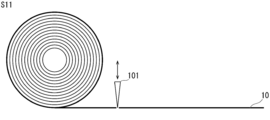
- the cutting step S11 is a step of cutting the long prepreg sheet 10 into pieces as shown in FIG. 2A.
- FIG. 2A corresponds to the cutting step S11 and is a schematic view showing a state in which the wound long prepreg sheet 10 is cut into individual pieces while being stretched while being stretched.
- the wound long prepreg sheet 10 is stretched, it is cut into pieces by a cutting blade 101 at regular intervals.
- the separated prepreg sheets 10 are conveyed to the stacking step S12.
- Lamination process S12 is a process of laminating the prepreg sheet 10 separated into pieces as shown in FIG. 2B.
- FIG. 2B is a schematic diagram showing a state in which the separated prepreg sheets 10 are laminated, corresponding to the lamination step S12 from the state of FIG. 2A.
- a plurality of the separated prepreg sheets 10 are stacked.
- several to several tens of prepreg sheets 10 are stacked in a stretched state so as not to cause wrinkles.
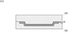
- the shaping step S13 is a step of preforming a plurality of laminated prepreg sheets 10 as shown in FIG. 2C.
- FIG. 2C is a schematic diagram showing a state in which the plurality of laminated prepreg sheets 10 are preformed according to the outer shape of the molded product 20 corresponding to the shaping step S13 from the state of FIG. 2B.
- the plurality of laminated prepreg sheets 10 are preformed by a preliminary mold (shaped shaping mold 102 and shaping movable mold 103).
- the shaping fixed mold 102 and the shaping movable mold 103 correspond to the main shapes of the molded product 20.
- the shaping movable mold 103 is lowered.
- the plurality of prepreg sheets 10 are sandwiched and clamped by the fixed mold 102 for shaping and the movable mold 103 for shaping.
- the surface layer curing step S ⁇ b> 14 is a step of curing the first prepreg sheet 10 ⁇ / b> P of the surface layer of the plurality of preformed prepreg sheets 10.
- FIG. 2D corresponds to the surface layer curing step S14 from the state of FIG. 2C, and shows a state in which the surface of the plurality of preformed prepreg sheets 10 is irradiated with light L to cure the surface first prepreg sheet 10P.
- FIG. 3 is a schematic diagram showing a state in which the resin (matrix resin 12) of the first prepreg sheet 10P of the surface layer among the plurality of prepreg sheets 10 is photocured in relation to the surface layer curing step S14 shown in FIG. 2D.
- the shaping moving mold 103 is separated from the shaping fixed mold 102, and the light source 104 is attached to the plurality of prepreg sheets 10 held by the shaping fixed mold 102. Make them face each other.
- the light source 104 includes a lamp, a light emitting diode, or a laser diode that emits light L including ultraviolet rays.
- the light source 104 is attached to a linear motion stage (not shown) in order to approach and separate from the auxiliary mold (the shaping fixed mold 102 and the shaping movable mold 103).
- Light L is emitted from the light source 104 to the surfaces of the plurality of prepreg sheets 10.
- the first matrix resin 12 ⁇ / b> P included in the first prepreg sheet 10 ⁇ / b> P that is at least the outermost surface and is exposed to the outside among the plurality of stacked prepreg sheets 10 is cured by the light L.
- the curing of the first matrix resin 12P in the surface layer curing step S14 includes not only the state where the curing is completed, but also the state where the curing has progressed to a hardness that maintains a certain regularity even when the curing is not completed.
- thermoforming step S15 is a step of thermosetting the entire plurality of prepreg sheets 10 in a state where only the surface layer is cured.
- FIG. 2E is a schematic diagram showing a state in which a plurality of prepreg sheets 10 in a state where only the surface layer is cured, corresponding to the thermoforming step S15, are thermally cured from the state of FIG. 2D.
- FIG. 4 is a diagram showing the relationship between the temperature and viscosity of the resin (matrix resin 12) of the prepreg sheet 10 in relation to the thermoforming step S15 shown in FIG. 2E.
- thermoforming fixed mold 105 and a thermoforming movable mold 106 At least one of the thermoforming fixed mold 105 and the thermoforming moving mold 106 incorporates a heater for heating.
- the thermoforming fixed mold 105 and the thermoforming moving mold 106 correspond to the shape of the molded product 20.
- the thermoforming movable mold 106 is lowered. A plurality of prepreg sheets 10 that have been preformed are sandwiched and clamped by the thermoforming fixed mold 105 and the thermoforming movable mold 106.
- the matrix resin 12 when the matrix resin 12 is heated to a plurality of laminated prepreg sheets 10 to increase the temperature, the viscosity is once lowered and the flow starts before curing.
- the curing of the first prepreg sheet 10 ⁇ / b> P as the surface layer has already been promoted in the surface layer curing step S ⁇ b> 14. Therefore, the flow of the matrix resin 12 can be suppressed without excessively decreasing the viscosity of the matrix resin 12 even when heat is input to the surfaces of the plurality of laminated prepreg sheets 10.
- the surface of the laminated prepreg sheets 10 can maintain a good appearance.
- the prepreg sheets 10 other than the first prepreg sheet 10P as the surface layer are not irradiated with the light L in the surface layer curing step S14. That is, in the prepreg sheets 10 other than the first prepreg sheet 10P on the surface layer, the flow of the impregnated matrix resin 12 starts with the input of heat in the thermoforming step S15. Therefore, in the prepreg sheet 10 other than the first prepreg sheet 10P on the surface layer, the matrix resin 12 can flow into the minute gaps between the adjacent prepreg sheets 10 in a state of low viscosity, thereby improving the impregnation property. For this reason, the laminated
- the demolding step S16 is a step of taking out a plurality of thermoset prepreg sheets 10 (molded products 20) from the mold.
- FIG. 2F corresponds to the demolding step S16 from the state of FIG. 2E, and is a state in which a plurality of thermoset prepreg sheets 10 (molded products 20) are taken out from the thermoforming stationary mold 105 and the thermoforming movable mold 106. It is a schematic diagram which shows.
- thermoforming movable mold 106 is separated from the thermoforming fixed mold 105, and the molded article 20 is removed. Take it out. Then, if necessary, the outer edge of the molded product 20 is cut with a cutting blade and finished (trim process). Further, the molded product 20 is painted (painting process).
- the molding method of the prepreg sheet 10 is a method of laminating and molding a prepreg sheet 10 formed by impregnating a base material (carbon fiber 11) with a resin (matrix resin 12).
- the first prepreg sheet 10 ⁇ / b> P included in the first prepreg sheet 10 ⁇ / b> P is started before curing of the second matrix resin 12 ⁇ / b> Q included in the second prepreg sheet 10 ⁇ / b> Q adjacent to the surface first prepreg sheet 10 ⁇ / b> P. Curing of 1 matrix resin 12P is completed.
- the first matrix resin 12 ⁇ / b> P of the first prepreg sheet 10 ⁇ / b> P on the surface layer of the laminated prepreg sheets 10 is cured, and then the second matrix resin of the second prepreg sheet 10 ⁇ / b> Q inside. 12Q is cured. That is, when the laminated prepreg sheet 10 is cured, even if the viscosity of the matrix resin 12 impregnated in the carbon fibers 11 decreases and flows inside the laminated prepreg sheet 10, the laminated prepreg sheet 10. The influence on the surface can be sufficiently suppressed. Therefore, according to the molding method of the prepreg sheet 10, a good appearance can be obtained.
- thermosetting properties In the method for forming the prepreg sheet 10, it is preferable to use a second matrix resin 12Q having thermosetting properties.
- thermosetting properties that are highly versatile and easy to control the curing.
- the first matrix resin 12P preferably has photocurability, and it is preferable to cure the first matrix resin 12P by irradiating the first prepreg sheet 10P with light L.
- the necessary portion (region) is irradiated with the light L and the necessary portion (region)
- the first matrix resin 12P in the region) can be selectively cured. Further, when the first matrix resin 12P is partially cured, it is necessary to irradiate the entire first prepreg sheet 10P with light L after masking other than necessary portions (areas) with a reflection sheet or the like. It is also possible to selectively cure the first matrix resin 12P in such a portion (region). Therefore, according to the method for forming the prepreg sheet 10, it is possible to select a necessary portion (region) and obtain a good appearance.
- the light L is absorbed by the first prepreg sheet 10P while entering the first prepreg sheet 10P. That is, it is possible to suppress the light L from reaching (incident on) the second prepreg sheet 10Q positioned just below the first prepreg sheet 10P and curing the second matrix resin 12Q of the second prepreg sheet 10Q. Since an interface is generated between the first prepreg sheet 10P and the second prepreg sheet 10Q, even if the light L is emitted from the first prepreg sheet 10P, it is incident on the second prepreg sheet 10Q. Can be difficult.
- the first matrix resin 12P has photocurability with respect to ultraviolet rays, and the first prepreg sheet 10P is irradiated with light L containing ultraviolet rays to cure the first matrix resin 12P. It is preferable.
- the first prepreg sheet 10 ⁇ / b> P can be efficiently cured by using the ultraviolet light L having a relatively short wavelength and high energy. Therefore, according to the molding method of the prepreg sheet 10, a good appearance can be obtained.
- the light L can be sufficiently attenuated inside the first prepreg sheet 10 ⁇ / b> P by using the ultraviolet light L having a relatively short wavelength and high energy. it can. That is, it is possible to suppress the light L from reaching (incident on) the second prepreg sheet 10Q positioned immediately below the first prepreg sheet 10P and curing the second matrix resin 12Q of the second prepreg sheet 10Q. Therefore, it is possible to selectively cure the first matrix resin 12P of the first prepreg sheet 10P located on the most surface layer among the plurality of stacked prepreg sheets 10. Therefore, according to the molding method of the prepreg sheet 10, a good appearance can be obtained.
- the base material preferably includes a plurality of carbon fibers 11 oriented in one direction.
- the method for forming the prepreg sheet 10 unevenness on the surface of the prepreg sheet 10 can be suppressed as compared with the case where a base material including carbon fibers that are configured as a woven fabric and have orientations alternately orthogonal to each other is used. Therefore, according to the molding method of the prepreg sheet 10, a good appearance can be obtained. Normally, when using a plurality of carbon fibers 11 oriented in one direction, the binding force in the direction perpendicular to the fiber is weak, and there is a concern that the orientation may be easily disturbed even by a slight flow of the resin. As in the embodiment, the first matrix resin 12P of the first prepreg sheet 10P on the surface layer is cured, and then the second matrix resin 12Q of the second prepreg sheet 10Q inside is cured, thereby eliminating the above-mentioned concern.
- the first matrix resin 12P of the first prepreg sheet 10P on the surface layer is cured, and then the second matrix resin 12Q of the second prepreg sheet 10Q inside is
- the molding method of the prepreg sheet 10 according to the second embodiment is related to the first embodiment in that the surface layer curing step is performed together with the shaping step (surface layer curing step and shaping step S23) as shown in FIG. This is different from the molding method of the prepreg sheet 10.
- surface layer hardening process S14 was performed after shaping process S13 and before thermoforming process S15.
- a method for forming the prepreg sheet 10 according to the second embodiment will be described with reference to FIG. 5 (flow chart of the second embodiment), FIG. 6 (1 of the second embodiment), and FIG. 7 (2 of the second embodiment). explain.
- the shaping fixed mold 102 and the shaping movable mold 203 or 303 when a plurality of laminated prepreg sheets 10 are preformed by a preliminary mold (the shaping fixed mold 102 and the shaping movable mold 203 or 303), a plurality of the prepreg sheets 10 laminated from the light source 104 are used.
- the light L is irradiated to the prepreg sheet 10. That is, the surface curing step and the shaping step are performed simultaneously.
- FIG. 5 is a flowchart showing a method of forming the prepreg sheet 10 according to the second embodiment.
- FIG. 6 corresponds to the surface layer curing step and the shaping step S23 according to 1 of the second embodiment, and the plurality of prepreg sheets 10 are irradiated with the light L that has passed through the shaping movable mold 203 to obtain the surface layer.
- It is a schematic diagram which shows the state which hardens the 1st prepreg sheet
- the shaping movable mold 203 has the same outer shape as the shaping movable mold 103 of the first embodiment, but the material is heat-resistant, such as synthetic quartz that transmits ultraviolet rays. Made of glass.
- the shaping movable mold 203 is not limited to synthetic quartz as long as it has heat resistance and transmits ultraviolet rays.
- the light source 104 is arranged behind the shaping movable mold 203. The light L derived from the light source 104 passes through the shaping movable mold 103 and is irradiated to the stacked prepreg sheets 10.
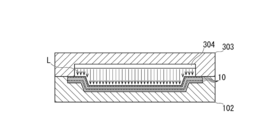
- FIG. 7 corresponds to the surface layer curing step and the shaping step S23 according to 2 of the second embodiment, and the plurality of prepreg sheets 10 are irradiated with light L from the inside of the shaping movable mold 303, and the surface layer It is a schematic diagram which shows the state which hardens the 1st prepreg sheet
- the shaping movable mold 303 has the same outer shape as the shaping movable mold 103 of the first embodiment, but includes a light source 304 at a portion facing the shaping fixed mold 102. ing. Further, in the shaping movable mold 303, a portion that transmits the light L emitted from the light source 304 to the outside is made of glass such as synthetic quartz.
- the light source 304 is composed of, for example, a light emitting diode or a laser diode. The light L derived from the light source 304 is applied to the stacked prepreg sheets 10.
- the method for forming the prepreg sheet 10 it is preferable to irradiate the laminated prepreg sheet 10 with light L and to form the prepreg sheet 10 after thermoforming.
- thermoforming can be performed after the surface layer is cured and the rigidity is improved while shaping the laminated prepreg sheet 10. That is, when the laminated prepreg sheet 10 is moved from the shaping process to the thermoforming process, the shape can be maintained and the positioning accuracy can be ensured. Therefore, according to the method for forming the prepreg sheet 10, it is possible to obtain a good appearance by eliminating the influence of the movement from the shaping process to the thermoforming process and the positioning accuracy in the thermoforming process.
- the molding method of the prepreg sheet 10 only the first matrix resin 12P is irradiated by irradiating the first prepreg sheet 10P with the light L in a state of eliminating the influence of heat in the shaping step without heating. Can be cured efficiently. Therefore, according to the method for forming the prepreg sheet 10, it is possible to eliminate the influence of heat and obtain a good appearance.
- the shaping movable mold 203 or the shaping movable mold 303 corresponding to the outer shape of the molded product 20 is pressed against the laminated prepreg sheet 10 to mold it, and the shaping movement is performed.
- the mold 203 or the shaping movable mold 303 preferably transmits the light L toward the laminated prepreg sheet 10.
- the surface prepreg sheet 10 can be cured in a state where the laminated prepreg sheet 10 is pressed (restrained) by the shaping movable mold 203 or the shaping movable mold 303. it can. That is, the laminated prepreg sheet 10 has good shape transferability of the shaping movable mold 203 or the shaping movable mold 303. Therefore, according to the method for forming the prepreg sheet 10, it is possible to obtain a good appearance in which the shape of the shaping movable mold 203 or the shaping movable mold 303 is transferred.
- the first prepreg sheet 10P on the surface layer is cured by irradiating with ultraviolet rays, but visible rays or infrared rays having wavelengths longer than the ultraviolet rays are irradiated. It may be configured to be cured.
- the carbon fibers 11 of the prepreg sheet 10 are oriented in one direction, but may be alternately woven. In this case, carbon fibers 11 that are alternately woven may be used for the prepreg sheets 10 other than the first prepreg sheet 10P on the surface layer.
- the surface layer curing step S14 is performed in the molds of the shaping step S13 (the shaping fixed mold 102 and the shaping movable mold 103) after the shaping step S13 is completed.
- the surface layer curing step S14 may be performed in the molds of the thermoforming step S15 (the thermoforming fixed die 105 and the thermoforming movable die 106) before the start of the thermoforming step S15.
- the shaping fixed mold 102 is formed of, for example, synthetic quartz, and the shaping fixed mold 102 is transmitted. It is good also as a structure which irradiates the surface of the prepreg sheet
- the thermoforming movable mold 106 or the thermoforming fixed mold 105 is formed of, for example, synthetic quartz, and the light L transmitted through the thermoforming movable mold 106 or the thermoforming fixed mold 105 is transmitted.
- the surface of the laminated prepreg sheet 10 may be irradiated. That is, the surface layer curing step of the second embodiment may be performed simultaneously with the thermoforming step S15 of the first embodiment.
- the matrix resin 12 (resin) is a resin having thermosetting properties, but a resin having thermoplasticity may be used.
Abstract
[Problem] To provide a method for molding a composite material capable of providing excellent appearance. [Solution] A method for molding a composite material (prepreg sheets 10) is a method which includes laminating and molding the prepreg sheets 10 obtained by impregnating a base material (carbon fibers 11) with a resin (matrix resin 12). According to the method for molding the prepreg sheets 10, curing of a first matrix resin 12P contained in a first prepreg sheet 10P is completed before curing of a second matrix resin 12Q contained in a second prepreg sheet 10Q adjacent to the first prepreg sheet 10P of a surface layer is started.
Description
本発明は、複合材料の成形方法に関する。
The present invention relates to a method for molding a composite material.
従来から、例えば基材(炭素繊維)に樹脂を含浸させてなる複合材料(プリプレグ)を積層した上で、熱成形して成形品を製造する技術が知られている(特許文献1を参照。)。特許文献1に記載の技術では、基材の表面粗さを小さくし、かつ、サイジング処理によって基材の結束性を向上させて、基材の乱れを抑制している。
2. Description of the Related Art Conventionally, for example, a technique of manufacturing a molded product by thermoforming after laminating a composite material (prepreg) obtained by impregnating a base material (carbon fiber) with a resin is known (see Patent Document 1). ). In the technique described in Patent Document 1, the surface roughness of the base material is reduced, and the binding property of the base material is improved by sizing treatment to suppress the disturbance of the base material.
特許文献1に記載の技術では、熱成形を行うときには依然として基材に含侵させている樹脂が流動して基材に乱れが発生することから、積層された複合材料の表面の凹凸を十分に抑制することは難しい。すなわち、特許文献1に記載の技術では、良好な外観を得ることが難しい。
In the technique described in Patent Document 1, since the resin impregnated in the base material still flows and the base material is disturbed when the thermoforming is performed, the unevenness of the surface of the laminated composite material is sufficiently obtained. It is difficult to suppress. That is, with the technique described in Patent Document 1, it is difficult to obtain a good appearance.
本発明の目的は、良好な外観を得ることができる複合材料の成形方法を提供することである。
An object of the present invention is to provide a molding method of a composite material that can obtain a good appearance.
上記目的を達成するための本発明の複合材料の成形方法は、基材に樹脂を含浸させてなる複合材料を積層して成形する方法である。この複合材料の成形方法では、表層の第1の前記複合材料に隣接する、第2の前記複合材料に含まれる第2の前記樹脂の硬化を開始する前に、第1の前記複合材料に含まれる第1の前記樹脂の硬化を完了させる。
The composite material molding method of the present invention for achieving the above object is a method in which a composite material obtained by impregnating a base material with a resin is laminated and molded. In this molding method of the composite material, before the curing of the second resin contained in the second composite material adjacent to the first composite material on the surface layer is started, the composite material is contained in the first composite material. Curing of the first resin is completed.
以下、添付した図面を参照しながら、本発明の第1実施形態および第2実施形態を説明する。図面において、同一の部材には同一の符号を付し、重複する説明を省略する。図面において、各部材の大きさや比率は、第1実施形態および第2実施形態の理解を容易にするために誇張し、実際の大きさや比率とは異なる場合がある。
Hereinafter, a first embodiment and a second embodiment of the present invention will be described with reference to the accompanying drawings. In the drawings, the same members are denoted by the same reference numerals, and redundant description is omitted. In the drawings, the size and ratio of each member are exaggerated to facilitate understanding of the first embodiment and the second embodiment, and may be different from the actual size and ratio.
(第1実施形態)
図3を参照して、第1実施形態にかかる複合材料(プリプレグシート10)の成形方法は、概説すれば、基材(炭素繊維11)に樹脂(マトリックス樹脂12)を含浸させてなるプリプレグシート10を積層して成形する方法である。このプリプレグシート10の成形方法では、表層の第1プリプレグシート10Pに隣接する、第2プリプレグシート10Qに含まれる第2マトリックス樹脂12Qの硬化を開始する前に、第1プリプレグシート10Pに含まれる第1マトリックス樹脂12Pの硬化を完了させる。 (First embodiment)
With reference to FIG. 3, the outline of the molding method of the composite material (prepreg sheet 10) according to the first embodiment is a prepreg sheet formed by impregnating a base material (carbon fiber 11) with a resin (matrix resin 12). 10 is a method of stacking and molding 10. In this method of forming theprepreg sheet 10, the first prepreg sheet 10 </ b> P included in the first prepreg sheet 10 </ b> P is started before curing of the second matrix resin 12 </ b> Q included in the second prepreg sheet 10 </ b> Q adjacent to the surface first prepreg sheet 10 </ b> P. Curing of 1 matrix resin 12P is completed.
図3を参照して、第1実施形態にかかる複合材料(プリプレグシート10)の成形方法は、概説すれば、基材(炭素繊維11)に樹脂(マトリックス樹脂12)を含浸させてなるプリプレグシート10を積層して成形する方法である。このプリプレグシート10の成形方法では、表層の第1プリプレグシート10Pに隣接する、第2プリプレグシート10Qに含まれる第2マトリックス樹脂12Qの硬化を開始する前に、第1プリプレグシート10Pに含まれる第1マトリックス樹脂12Pの硬化を完了させる。 (First embodiment)
With reference to FIG. 3, the outline of the molding method of the composite material (prepreg sheet 10) according to the first embodiment is a prepreg sheet formed by impregnating a base material (carbon fiber 11) with a resin (matrix resin 12). 10 is a method of stacking and molding 10. In this method of forming the
ここで、表層の第1プリプレグシート10Pは、裏面の一層(最裏層)のプリプレグシート10以外の全てのプリプレグシート10に該当する。すなわち、表層の第1プリプレグシート10Pは、積層した複数のプリプレグシート10のうち、例えば、表面側において外部に露出している一層(最表層)のみであってもよいし、裏面側において外部に露出している一層(最裏層)を除く複数の層であってもよい。
Here, the first prepreg sheet 10P on the surface layer corresponds to all the prepreg sheets 10 other than the prepreg sheet 10 on the back layer (the backmost layer). That is, the first prepreg sheet 10P on the surface layer may be, for example, only one layer (outermost layer) exposed to the outside on the front surface side among the plurality of stacked prepreg sheets 10, or may be externally exposed on the back surface side. A plurality of layers other than the exposed one layer (the backmost layer) may be used.
(プリプレグシート10)
プリプレグシート10(複合材料)は、基材(炭素繊維11)に樹脂(マトリックス樹脂12)を含浸させて、長尺な薄板形状に形成している。プリプレグシート10を用いて、炭素繊維強化プラスチック(carbon fiber reinforced plastic:CFRP)からなる成形品20を成形する。 (Prepreg sheet 10)
The prepreg sheet 10 (composite material) is formed into a long thin plate shape by impregnating a base material (carbon fiber 11) with a resin (matrix resin 12). Aprepreg sheet 10 is used to form a molded article 20 made of carbon fiber reinforced plastic (CFRP).
プリプレグシート10(複合材料)は、基材(炭素繊維11)に樹脂(マトリックス樹脂12)を含浸させて、長尺な薄板形状に形成している。プリプレグシート10を用いて、炭素繊維強化プラスチック(carbon fiber reinforced plastic:CFRP)からなる成形品20を成形する。 (Prepreg sheet 10)
The prepreg sheet 10 (composite material) is formed into a long thin plate shape by impregnating a base material (carbon fiber 11) with a resin (matrix resin 12). A
基材は、炭素繊維11に限定されることなく、ガラス繊維や有機繊維等から構成することができる。炭素繊維11は、一方向に配向した長繊維を用いることによって、繊維の配向がランダムな短繊維を用いる場合と比較して、繊維の配向性を均一化している。すなわち、長繊維の炭素繊維11を用いることによって、繊維の乱れに起因するシワ、ヨレ、および凹凸を抑制している。
The base material is not limited to the carbon fiber 11 and can be made of glass fiber, organic fiber, or the like. The carbon fiber 11 uses a long fiber oriented in one direction to make the orientation of the fiber uniform as compared with a case where a short fiber with a random fiber orientation is used. That is, the use of the long carbon fiber 11 suppresses wrinkles, twists, and irregularities caused by fiber disturbance.
マトリックス樹脂12は、例えば、光硬化性および熱硬化性を備えたエポキシ樹脂や、光硬化性および熱硬化性を備えたアクリル系やウレタン系の樹脂から構成する。マトリックス樹脂12は、積層する複数のプリプレグシート10のうち、少なくとも最表面であって外部に露出している第1プリプレグシート10Pのみ、光硬化性を備えていればよい。
The matrix resin 12 is composed of, for example, an epoxy resin having photocurability and thermosetting, or an acrylic or urethane resin having photocuring and thermosetting properties. The matrix resin 12 only needs to have photocurability only in the first prepreg sheet 10P which is at least the outermost surface and is exposed to the outside among the plurality of prepreg sheets 10 to be laminated.
(プリプレグシート10の成形方法)
プリプレグシート10の成形方法は、次のような工程によって、具現化される。すなわち、プリプレグシート10の成形方法は、長尺なプリプレグシート10を切断して個片化する切断工程S11、個片化されたプリプレグシート10を積層する積層工程S12、および積層された複数のプリプレグシート10を予備成形する賦形工程S13によって具現化される。さらに、プリプレグシート10の成形方法は、予備成形された複数のプリプレグシート10の表層の第1プリプレグシート10Pを硬化させる表層硬化工程S14、表層のみ硬化された状態の複数のプリプレグシート10全体を熱硬化させる熱成形工程S15、および熱硬化させた複数のプリプレグシート10(成形品20)を型から取り出す脱型工程S16によって具現化される。 (Forming method of prepreg sheet 10)
The forming method of theprepreg sheet 10 is embodied by the following steps. That is, the method for forming the prepreg sheet 10 includes a cutting step S11 for cutting the long prepreg sheet 10 into individual pieces, a stacking step S12 for stacking the separated prepreg sheets 10, and a plurality of stacked prepregs. This is embodied by a shaping step S13 for preforming the sheet 10. Further, the method for forming the prepreg sheet 10 includes a surface layer curing step S14 for curing the first prepreg sheet 10P on the surface layer of the plurality of preformed prepreg sheets 10, and heating the entire prepreg sheet 10 in a state where only the surface layer is cured. It is embodied by a thermoforming step S15 for curing, and a demolding step S16 for removing a plurality of thermoset prepreg sheets 10 (molded products 20) from the mold.
プリプレグシート10の成形方法は、次のような工程によって、具現化される。すなわち、プリプレグシート10の成形方法は、長尺なプリプレグシート10を切断して個片化する切断工程S11、個片化されたプリプレグシート10を積層する積層工程S12、および積層された複数のプリプレグシート10を予備成形する賦形工程S13によって具現化される。さらに、プリプレグシート10の成形方法は、予備成形された複数のプリプレグシート10の表層の第1プリプレグシート10Pを硬化させる表層硬化工程S14、表層のみ硬化された状態の複数のプリプレグシート10全体を熱硬化させる熱成形工程S15、および熱硬化させた複数のプリプレグシート10(成形品20)を型から取り出す脱型工程S16によって具現化される。 (Forming method of prepreg sheet 10)
The forming method of the
プリプレグシート10の成形方法(切断工程S11~脱型工程S16によって具現化)を、図1および図2A~図2Fを参照しつつ説明する。図1は、プリプレグシート10の成形方法を示すフローチャートである。図2A~図2Fは、プリプレグシート10の成形方法を示す模式図である。
A method for forming the prepreg sheet 10 (implemented by the cutting step S11 to the demolding step S16) will be described with reference to FIGS. 1 and 2A to 2F. FIG. 1 is a flowchart showing a method for forming the prepreg sheet 10. 2A to 2F are schematic views showing a method for forming the prepreg sheet 10. FIG.
(切断工程S11)
切断工程S11は、図2Aに示すように、長尺なプリプレグシート10を切断して個片化する工程である。 (Cutting step S11)
The cutting step S11 is a step of cutting thelong prepreg sheet 10 into pieces as shown in FIG. 2A.
切断工程S11は、図2Aに示すように、長尺なプリプレグシート10を切断して個片化する工程である。 (Cutting step S11)
The cutting step S11 is a step of cutting the
図2Aは、切断工程S11に相当し、巻回された長尺なプリプレグシート10を伸長させつつ一定の間隔毎に切断して個片化する状態を示す模式図である。
FIG. 2A corresponds to the cutting step S11 and is a schematic view showing a state in which the wound long prepreg sheet 10 is cut into individual pieces while being stretched while being stretched.
図2Aに示すように、巻回された長尺状のプリプレグシート10を伸長させつつ、一定の間隔毎に、切断刃101によって切断して個片化する。個片化されたプリプレグシート10は、積層工程S12に搬送される。
As shown in FIG. 2A, while the wound long prepreg sheet 10 is stretched, it is cut into pieces by a cutting blade 101 at regular intervals. The separated prepreg sheets 10 are conveyed to the stacking step S12.
(積層工程S12)
積層工程S12は、図2Bに示すように、個片化されたプリプレグシート10を積層する工程である。 (Lamination process S12)
Lamination process S12 is a process of laminating theprepreg sheet 10 separated into pieces as shown in FIG. 2B.
積層工程S12は、図2Bに示すように、個片化されたプリプレグシート10を積層する工程である。 (Lamination process S12)
Lamination process S12 is a process of laminating the
図2Bは、図2Aの状態から引き続き、積層工程S12に相当し、個片化されたプリプレグシート10を積層する状態を示す模式図である。
FIG. 2B is a schematic diagram showing a state in which the separated prepreg sheets 10 are laminated, corresponding to the lamination step S12 from the state of FIG. 2A.
図2Bに示すように、個片化されたプリプレグシート10を複数枚積み重ねる。プリプレグシート10は、皺を生じないように伸長させた状態において、成形品20の厚みに応じて、数枚から数十枚積み重ねる。
As shown in FIG. 2B, a plurality of the separated prepreg sheets 10 are stacked. Depending on the thickness of the molded product 20, several to several tens of prepreg sheets 10 are stacked in a stretched state so as not to cause wrinkles.
(賦形工程S13)
賦形工程S13は、図2Cに示すように、積層された複数のプリプレグシート10を予備成形する工程である。 (Shaping process S13)
The shaping step S13 is a step of preforming a plurality oflaminated prepreg sheets 10 as shown in FIG. 2C.
賦形工程S13は、図2Cに示すように、積層された複数のプリプレグシート10を予備成形する工程である。 (Shaping process S13)
The shaping step S13 is a step of preforming a plurality of
図2Cは、図2Bの状態から引き続き、賦形工程S13に相当し、積層された複数のプリプレグシート10を成形品20の外形形状に合わせて予備成形する状態を示す模式図である。
FIG. 2C is a schematic diagram showing a state in which the plurality of laminated prepreg sheets 10 are preformed according to the outer shape of the molded product 20 corresponding to the shaping step S13 from the state of FIG. 2B.
図2Cに示すように、積層された複数のプリプレグシート10を予備金型(賦形用固定型102および賦形用移動型103)によって予備成形する。賦形用固定型102および賦形用移動型103は、成形品20の主要な形状に対応している。賦形用移動型103を上昇させて、賦形用固定型102に対して複数のプリプレグシート10を載置した後、賦形用移動型103を降下させる。賦形用固定型102および賦形用移動型103によって、複数のプリプレグシート10を挟み込んで型締めする。
As shown in FIG. 2C, the plurality of laminated prepreg sheets 10 are preformed by a preliminary mold (shaped shaping mold 102 and shaping movable mold 103). The shaping fixed mold 102 and the shaping movable mold 103 correspond to the main shapes of the molded product 20. After moving the shaping movable mold 103 and placing the plurality of prepreg sheets 10 on the shaping fixed mold 102, the shaping movable mold 103 is lowered. The plurality of prepreg sheets 10 are sandwiched and clamped by the fixed mold 102 for shaping and the movable mold 103 for shaping.
(表層硬化工程S14)
表層硬化工程S14は、図2Dおよび図3に示すように、予備成形された複数のプリプレグシート10の表層の第1プリプレグシート10Pを硬化させる工程である。 (Surface layer curing step S14)
As shown in FIGS. 2D and 3, the surface layer curing step S <b> 14 is a step of curing thefirst prepreg sheet 10 </ b> P of the surface layer of the plurality of preformed prepreg sheets 10.
表層硬化工程S14は、図2Dおよび図3に示すように、予備成形された複数のプリプレグシート10の表層の第1プリプレグシート10Pを硬化させる工程である。 (Surface layer curing step S14)
As shown in FIGS. 2D and 3, the surface layer curing step S <b> 14 is a step of curing the
図2Dは、図2Cの状態から引き続き、表層硬化工程S14に相当し、予備成形された複数のプリプレグシート10の表面に光Lを照射して表層の第1プリプレグシート10Pを硬化させる状態を示す模式図である。図3は、図2Dに示す表層硬化工程S14に関連し、複数のプリプレグシート10のうち表層の第1プリプレグシート10Pの樹脂(マトリックス樹脂12)を光硬化させる状態を示す模式図である。
FIG. 2D corresponds to the surface layer curing step S14 from the state of FIG. 2C, and shows a state in which the surface of the plurality of preformed prepreg sheets 10 is irradiated with light L to cure the surface first prepreg sheet 10P. It is a schematic diagram. FIG. 3 is a schematic diagram showing a state in which the resin (matrix resin 12) of the first prepreg sheet 10P of the surface layer among the plurality of prepreg sheets 10 is photocured in relation to the surface layer curing step S14 shown in FIG. 2D.
図2Dおよび図3に示すように、賦形用固定型102から賦形用移動型103を離間させ、賦形用固定型102に保持されている複数のプリプレグシート10に対して、光源104を対向させる。光源104は、紫外線を含む光Lを発するランプや発光ダイオードまたはレーザダイオードから構成する。光源104は、予備金型(賦形用固定型102および賦形用移動型103)に接近および離間させるために、直動ステージ(不図示)に取り付けされている。光源104から複数のプリプレグシート10の表面に対して光Lを照射する。図3に示すように、積層した複数のプリプレグシート10のうち、少なくとも最表面であって外部に露出している第1プリプレグシート10Pに含まれる第1マトリックス樹脂12Pを、光Lによって硬化させる。
As shown in FIGS. 2D and 3, the shaping moving mold 103 is separated from the shaping fixed mold 102, and the light source 104 is attached to the plurality of prepreg sheets 10 held by the shaping fixed mold 102. Make them face each other. The light source 104 includes a lamp, a light emitting diode, or a laser diode that emits light L including ultraviolet rays. The light source 104 is attached to a linear motion stage (not shown) in order to approach and separate from the auxiliary mold (the shaping fixed mold 102 and the shaping movable mold 103). Light L is emitted from the light source 104 to the surfaces of the plurality of prepreg sheets 10. As shown in FIG. 3, the first matrix resin 12 </ b> P included in the first prepreg sheet 10 </ b> P that is at least the outermost surface and is exposed to the outside among the plurality of stacked prepreg sheets 10 is cured by the light L.
表層硬化工程S14における第1マトリックス樹脂12Pの硬化は、硬化が完了した状態に加えて、硬化が未完了であっても一定の定形性を保つ硬度まで硬化が進んだ状態も含む。
The curing of the first matrix resin 12P in the surface layer curing step S14 includes not only the state where the curing is completed, but also the state where the curing has progressed to a hardness that maintains a certain regularity even when the curing is not completed.
(熱成形工程S15)
熱成形工程S15は、図2Eおよび図4に示すように、表層のみ硬化された状態の複数のプリプレグシート10全体を熱硬化させる工程である。 (Thermoforming process S15)
As shown in FIGS. 2E and 4, the thermoforming step S <b> 15 is a step of thermosetting the entire plurality ofprepreg sheets 10 in a state where only the surface layer is cured.
熱成形工程S15は、図2Eおよび図4に示すように、表層のみ硬化された状態の複数のプリプレグシート10全体を熱硬化させる工程である。 (Thermoforming process S15)
As shown in FIGS. 2E and 4, the thermoforming step S <b> 15 is a step of thermosetting the entire plurality of
図2Eは、図2Dの状態から引き続き、熱成形工程S15に相当し、表層のみ硬化された状態の複数のプリプレグシート10を熱硬化させる状態を示す模式図である。図4は、図2Eに示す熱成形工程S15に関連し、プリプレグシート10の樹脂(マトリックス樹脂12)の温度と粘度の関係を示す図である。
FIG. 2E is a schematic diagram showing a state in which a plurality of prepreg sheets 10 in a state where only the surface layer is cured, corresponding to the thermoforming step S15, are thermally cured from the state of FIG. 2D. FIG. 4 is a diagram showing the relationship between the temperature and viscosity of the resin (matrix resin 12) of the prepreg sheet 10 in relation to the thermoforming step S15 shown in FIG. 2E.
図2Eに示すように、予備成形を終えている複数のプリプレグシート10を金型(熱成形用固定型105および熱成形用移動型106)によって本成形する。熱成形用固定型105および熱成形用移動型106は、少なくとも一方に加熱用のヒータを内蔵している。熱成形用固定型105および熱成形用移動型106は、成形品20の形状に対応している。熱成形用移動型106を上昇させて、熱成形用固定型105に対して予備成形を終えている複数のプリプレグシート10を載置した後、熱成形用移動型106を降下させる。熱成形用固定型105および熱成形用移動型106によって、予備成形を終えている複数のプリプレグシート10を挟み込んで型締めする。
As shown in FIG. 2E, a plurality of prepreg sheets 10 that have been preformed are formed by a mold (a thermoforming fixed mold 105 and a thermoforming movable mold 106). At least one of the thermoforming fixed mold 105 and the thermoforming moving mold 106 incorporates a heater for heating. The thermoforming fixed mold 105 and the thermoforming moving mold 106 correspond to the shape of the molded product 20. After moving the thermoforming movable mold 106 and placing the plurality of prepreg sheets 10 that have been preformed on the thermoforming fixed mold 105, the thermoforming movable mold 106 is lowered. A plurality of prepreg sheets 10 that have been preformed are sandwiched and clamped by the thermoforming fixed mold 105 and the thermoforming movable mold 106.
図4に示すように、マトリックス樹脂12は、積層された複数のプリプレグシート10に熱が入力されて昇温すると、硬化に至る前に粘度が一旦下がって流動が始まる。ここで、積層された複数のプリプレグシート10のうち、表層の第1プリプレグシート10Pは、既に表層硬化工程S14において硬化が促進されている。したがって、積層された複数のプリプレグシート10の表面については、熱が入力されても、マトリックス樹脂12の粘度が極端に下がることなく、マトリックス樹脂12の流動を抑制することができる。すなわち、積層された複数のプリプレグシート10の表面については、熱が入力されても、炭素繊維11の配向が乱されることなく、繊維の乱れに起因するシワ、ヨレ、凹凸、および局所的な引けを抑制することができる。したがって、積層された複数のプリプレグシート10の表面は、外観を良好に維持することができる。
As shown in FIG. 4, when the matrix resin 12 is heated to a plurality of laminated prepreg sheets 10 to increase the temperature, the viscosity is once lowered and the flow starts before curing. Here, among the plurality of laminated prepreg sheets 10, the curing of the first prepreg sheet 10 </ b> P as the surface layer has already been promoted in the surface layer curing step S <b> 14. Therefore, the flow of the matrix resin 12 can be suppressed without excessively decreasing the viscosity of the matrix resin 12 even when heat is input to the surfaces of the plurality of laminated prepreg sheets 10. That is, with respect to the surfaces of the plurality of laminated prepreg sheets 10, even if heat is input, the orientation of the carbon fibers 11 is not disturbed, and wrinkles, twists, irregularities, and localities caused by the disorder of the fibers. Close can be suppressed. Therefore, the surface of the laminated prepreg sheets 10 can maintain a good appearance.
積層された複数のプリプレグシート10のうち、表層の第1プリプレグシート10P以外のプリプレグシート10は、表層硬化工程S14において光Lを照射されていない。すなわち、表層の第1プリプレグシート10P以外のプリプレグシート10は、熱成形工程S15における熱の入力に伴い、含侵されているマトリックス樹脂12の流動が始まる。したがって、表層の第1プリプレグシート10P以外のプリプレグシート10において、マトリックス樹脂12は、隣接するプリプレグシート10の微小な隙間にも、粘度が低い状態で流れ込み、含浸性を高めることができる。このため、積層された複数のプリプレグシート10は、外観を良好に維持しつつ、ボイド等に起因する剥離強度の低下や耐久性の低下を防止することができる。
Among the plurality of laminated prepreg sheets 10, the prepreg sheets 10 other than the first prepreg sheet 10P as the surface layer are not irradiated with the light L in the surface layer curing step S14. That is, in the prepreg sheets 10 other than the first prepreg sheet 10P on the surface layer, the flow of the impregnated matrix resin 12 starts with the input of heat in the thermoforming step S15. Therefore, in the prepreg sheet 10 other than the first prepreg sheet 10P on the surface layer, the matrix resin 12 can flow into the minute gaps between the adjacent prepreg sheets 10 in a state of low viscosity, thereby improving the impregnation property. For this reason, the laminated | stacked several prepreg sheet | seat 10 can prevent the fall of the peeling strength resulting from a void etc. and the fall of durability, maintaining a favorable appearance.
(脱型工程S16)
脱型工程S16は、図2Fに示すように、熱硬化させた複数のプリプレグシート10(成形品20)を型から取り出す工程である。 (Demolding step S16)
As shown in FIG. 2F, the demolding step S16 is a step of taking out a plurality of thermoset prepreg sheets 10 (molded products 20) from the mold.
脱型工程S16は、図2Fに示すように、熱硬化させた複数のプリプレグシート10(成形品20)を型から取り出す工程である。 (Demolding step S16)
As shown in FIG. 2F, the demolding step S16 is a step of taking out a plurality of thermoset prepreg sheets 10 (molded products 20) from the mold.
図2Fは、図2Eの状態から引き続き、脱型工程S16に相当し、熱硬化させた複数のプリプレグシート10(成形品20)を熱成形用固定型105および熱成形用移動型106から取り出す状態を示す模式図である。
FIG. 2F corresponds to the demolding step S16 from the state of FIG. 2E, and is a state in which a plurality of thermoset prepreg sheets 10 (molded products 20) are taken out from the thermoforming stationary mold 105 and the thermoforming movable mold 106. It is a schematic diagram which shows.
図2Fに示すように、熱硬化させた複数のプリプレグシート10(成形品20)を室温まで冷却した後、熱成形用固定型105から熱成形用移動型106を離間させて、成形品20を外部に取り出す。その後、必要に応じて、成形品20の外縁を切断刃によって切断して仕上げる(トリム工程)。また、成形品20に塗装を行う(塗装工程)。
As shown in FIG. 2F, after the plurality of heat-cured prepreg sheets 10 (molded articles 20) are cooled to room temperature, the thermoforming movable mold 106 is separated from the thermoforming fixed mold 105, and the molded article 20 is removed. Take it out. Then, if necessary, the outer edge of the molded product 20 is cut with a cutting blade and finished (trim process). Further, the molded product 20 is painted (painting process).
以上説明した第1実施形態の作用効果を説明する。
The operational effects of the first embodiment described above will be described.
プリプレグシート10の成形方法は、基材(炭素繊維11)に樹脂(マトリックス樹脂12)を含浸させてなるプリプレグシート10を積層して成形する方法である。このプリプレグシート10の成形方法では、表層の第1プリプレグシート10Pに隣接する、第2プリプレグシート10Qに含まれる第2マトリックス樹脂12Qの硬化を開始する前に、第1プリプレグシート10Pに含まれる第1マトリックス樹脂12Pの硬化を完了させる。
The molding method of the prepreg sheet 10 is a method of laminating and molding a prepreg sheet 10 formed by impregnating a base material (carbon fiber 11) with a resin (matrix resin 12). In this method of forming the prepreg sheet 10, the first prepreg sheet 10 </ b> P included in the first prepreg sheet 10 </ b> P is started before curing of the second matrix resin 12 </ b> Q included in the second prepreg sheet 10 </ b> Q adjacent to the surface first prepreg sheet 10 </ b> P. Curing of 1 matrix resin 12P is completed.
かかるプリプレグシート10の成形方法によれば、積層したプリプレグシート10のうち、表層の第1プリプレグシート10Pの第1マトリックス樹脂12Pを硬化させてから、内部の第2プリプレグシート10Qの第2マトリックス樹脂12Qを硬化させる。すなわち、積層したプリプレグシート10を硬化させるときに、積層したプリプレグシート10の内部において、炭素繊維11に含侵させているマトリックス樹脂12の粘度が低下して流動しても、積層したプリプレグシート10の表面への影響を十分に抑制することができる。したがって、かかるプリプレグシート10の成形方法によれば、良好な外観を得ることができる。
According to the molding method of the prepreg sheet 10, the first matrix resin 12 </ b> P of the first prepreg sheet 10 </ b> P on the surface layer of the laminated prepreg sheets 10 is cured, and then the second matrix resin of the second prepreg sheet 10 </ b> Q inside. 12Q is cured. That is, when the laminated prepreg sheet 10 is cured, even if the viscosity of the matrix resin 12 impregnated in the carbon fibers 11 decreases and flows inside the laminated prepreg sheet 10, the laminated prepreg sheet 10. The influence on the surface can be sufficiently suppressed. Therefore, according to the molding method of the prepreg sheet 10, a good appearance can be obtained.
プリプレグシート10の成形方法において、第2マトリックス樹脂12Qは、熱硬化性を備えたものを用いることが好ましい。
In the method for forming the prepreg sheet 10, it is preferable to use a second matrix resin 12Q having thermosetting properties.
かかるプリプレグシート10の成形方法によれば、汎用性が高く硬化の制御が容易な熱硬化性を備えた第2マトリックス樹脂12Qを用いて成形することができる。
According to the molding method of the prepreg sheet 10, it is possible to mold using the second matrix resin 12Q having thermosetting properties that are highly versatile and easy to control the curing.
プリプレグシート10の成形方法において、第1マトリックス樹脂12Pは、光硬化性を備え、第1プリプレグシート10Pに対して光Lを照射して第1マトリックス樹脂12Pを硬化させることが好ましい。
In the molding method of the prepreg sheet 10, the first matrix resin 12P preferably has photocurability, and it is preferable to cure the first matrix resin 12P by irradiating the first prepreg sheet 10P with light L.
かかるプリプレグシート10の成形方法によれば、第1プリプレグシート10Pの第1マトリックス樹脂12Pを部分的に硬化させる場合、必要な部分(領域)に対して光Lを照射して、必要な部分(領域)の第1マトリックス樹脂12Pを選択的に硬化させることができる。また、第1マトリックス樹脂12Pを部分的に硬化させる場合、必要な部分(領域)以外を反射シート等によってマスキングした上で、第1プリプレグシート10Pの全体に対して光Lを照射して、必要な部分(領域)の第1マトリックス樹脂12Pを選択的に硬化させることもできる。したがって、かかるプリプレグシート10の成形方法によれば、必要な部分(領域)を選択して、良好な外観を得ることができる。
According to the molding method of the prepreg sheet 10, when the first matrix resin 12P of the first prepreg sheet 10P is partially cured, the necessary portion (region) is irradiated with the light L and the necessary portion (region) The first matrix resin 12P in the region) can be selectively cured. Further, when the first matrix resin 12P is partially cured, it is necessary to irradiate the entire first prepreg sheet 10P with light L after masking other than necessary portions (areas) with a reflection sheet or the like. It is also possible to selectively cure the first matrix resin 12P in such a portion (region). Therefore, according to the method for forming the prepreg sheet 10, it is possible to select a necessary portion (region) and obtain a good appearance.
さらに、かかるプリプレグシート10の成形方法によれば、光Lが第1プリプレグシート10Pに入射しつつ第1プリプレグシート10Pに吸収される。すなわち、光Lが第1プリプレグシート10Pの真下に位置する第2プリプレグシート10Qに到達(入射)して第2プリプレグシート10Qの第2マトリックス樹脂12Qを硬化させることを抑制できる。なお、第1プリプレグシート10Pと、第2プリプレグシート10Qの間には、界面が発生することから、仮に、光Lが第1プリプレグシート10Pから出射しても、第2プリプレグシート10Qに入射させ難くすることができる。したがって、積層した複数のプリプレグシート10のうち、最も表層に位置する第1プリプレグシート10Pの第1マトリックス樹脂12Pを選択的に硬化させることができる。したがって、かかるプリプレグシート10の成形方法によれば、必要な部分(領域)を選択して、良好な外観を得ることができる。
Furthermore, according to the method for forming the prepreg sheet 10, the light L is absorbed by the first prepreg sheet 10P while entering the first prepreg sheet 10P. That is, it is possible to suppress the light L from reaching (incident on) the second prepreg sheet 10Q positioned just below the first prepreg sheet 10P and curing the second matrix resin 12Q of the second prepreg sheet 10Q. Since an interface is generated between the first prepreg sheet 10P and the second prepreg sheet 10Q, even if the light L is emitted from the first prepreg sheet 10P, it is incident on the second prepreg sheet 10Q. Can be difficult. Therefore, it is possible to selectively cure the first matrix resin 12P of the first prepreg sheet 10P located on the most surface layer among the plurality of stacked prepreg sheets 10. Therefore, according to the method for forming the prepreg sheet 10, it is possible to select a necessary portion (region) and obtain a good appearance.
プリプレグシート10の成形方法において、第1マトリックス樹脂12Pは、紫外線に対して光硬化性を備え、第1プリプレグシート10Pに対して紫外線を含む光Lを照射して第1マトリックス樹脂12Pを硬化させることが好ましい。
In the molding method of the prepreg sheet 10, the first matrix resin 12P has photocurability with respect to ultraviolet rays, and the first prepreg sheet 10P is irradiated with light L containing ultraviolet rays to cure the first matrix resin 12P. It is preferable.
かかるプリプレグシート10の成形方法によれば、相対的に短波長であってエネルギーが大きい紫外線の光Lを用いることによって、第1プリプレグシート10Pを効率良く硬化させることができる。したがって、かかるプリプレグシート10の成形方法によれば、良好な外観を得ることができる。
According to the molding method of the prepreg sheet 10, the first prepreg sheet 10 </ b> P can be efficiently cured by using the ultraviolet light L having a relatively short wavelength and high energy. Therefore, according to the molding method of the prepreg sheet 10, a good appearance can be obtained.
さらに、かかるプリプレグシート10の成形方法によれば、相対的に短波長であってエネルギーが大きい紫外線の光Lを用いることによって、光Lを第1プリプレグシート10Pの内部で十分に減衰させることができる。すなわち、光Lが第1プリプレグシート10Pの真下に位置する第2プリプレグシート10Qに到達(入射)して、第2プリプレグシート10Qの第2マトリックス樹脂12Qを硬化させることを抑制できる。したがって、積層した複数のプリプレグシート10のうち、最も表層に位置する第1プリプレグシート10Pの第1マトリックス樹脂12Pを選択的に硬化させることができる。したがって、かかるプリプレグシート10の成形方法によれば、良好な外観を得ることができる。
Furthermore, according to the method for forming the prepreg sheet 10, the light L can be sufficiently attenuated inside the first prepreg sheet 10 </ b> P by using the ultraviolet light L having a relatively short wavelength and high energy. it can. That is, it is possible to suppress the light L from reaching (incident on) the second prepreg sheet 10Q positioned immediately below the first prepreg sheet 10P and curing the second matrix resin 12Q of the second prepreg sheet 10Q. Therefore, it is possible to selectively cure the first matrix resin 12P of the first prepreg sheet 10P located on the most surface layer among the plurality of stacked prepreg sheets 10. Therefore, according to the molding method of the prepreg sheet 10, a good appearance can be obtained.
プリプレグシート10の成形方法において、基材は、一方向に配向した複数の炭素繊維11を含むことが好ましい。
In the method for forming the prepreg sheet 10, the base material preferably includes a plurality of carbon fibers 11 oriented in one direction.
かかるプリプレグシート10の成形方法によれば、織物として構成し配向が交互に直交する炭素繊維を含む基材を用いる場合と比較して、プリプレグシート10の表面の凹凸を抑制することができる。したがって、かかるプリプレグシート10の成形方法によれば、良好な外観を得ることができる。なお、通常は、一方向に配向した複数の炭素繊維11を用いる場合、繊維直交方向の拘束力が弱く、樹脂のわずかな流動でも容易に配向が乱される等が懸念されるが、第1実施形態のように、表層の第1プリプレグシート10Pの第1マトリックス樹脂12Pを硬化させてから、内部の第2プリプレグシート10Qの第2マトリックス樹脂12Qを硬化させることによって、上記の懸念は解消される。
According to the method for forming the prepreg sheet 10, unevenness on the surface of the prepreg sheet 10 can be suppressed as compared with the case where a base material including carbon fibers that are configured as a woven fabric and have orientations alternately orthogonal to each other is used. Therefore, according to the molding method of the prepreg sheet 10, a good appearance can be obtained. Normally, when using a plurality of carbon fibers 11 oriented in one direction, the binding force in the direction perpendicular to the fiber is weak, and there is a concern that the orientation may be easily disturbed even by a slight flow of the resin. As in the embodiment, the first matrix resin 12P of the first prepreg sheet 10P on the surface layer is cured, and then the second matrix resin 12Q of the second prepreg sheet 10Q inside is cured, thereby eliminating the above-mentioned concern. The
(第2実施形態)
第2実施形態にかかるプリプレグシート10の成形方法は、図5に示すように表層硬化工程を賦形工程と共に行う(表層硬化工程および賦形工程S23)点において、上記の第1実施形態にかかるプリプレグシート10の成形方法と相違する。上記の第1実施形態では、表層硬化工程S14を、賦形工程S13の後であって熱成形工程S15の前に行っていた。 (Second Embodiment)
The molding method of theprepreg sheet 10 according to the second embodiment is related to the first embodiment in that the surface layer curing step is performed together with the shaping step (surface layer curing step and shaping step S23) as shown in FIG. This is different from the molding method of the prepreg sheet 10. In said 1st Embodiment, surface layer hardening process S14 was performed after shaping process S13 and before thermoforming process S15.
第2実施形態にかかるプリプレグシート10の成形方法は、図5に示すように表層硬化工程を賦形工程と共に行う(表層硬化工程および賦形工程S23)点において、上記の第1実施形態にかかるプリプレグシート10の成形方法と相違する。上記の第1実施形態では、表層硬化工程S14を、賦形工程S13の後であって熱成形工程S15の前に行っていた。 (Second Embodiment)
The molding method of the
第2実施形態にかかるプリプレグシート10の成形方法を、図5(第2実施形態のフローチャート)、図6(第2実施形態の1)および図7(第2実施形態の2)を参照しつつ説明する。
A method for forming the prepreg sheet 10 according to the second embodiment will be described with reference to FIG. 5 (flow chart of the second embodiment), FIG. 6 (1 of the second embodiment), and FIG. 7 (2 of the second embodiment). explain.
第2実施形態では、積層された複数のプリプレグシート10を予備金型(賦形用固定型102および賦形用移動型203または303)によって予備成形するときに、光源104から積層された複数のプリプレグシート10に対して光Lを照射する。すなわち、表層硬化工程と賦形工程を同時に行う。
In the second embodiment, when a plurality of laminated prepreg sheets 10 are preformed by a preliminary mold (the shaping fixed mold 102 and the shaping movable mold 203 or 303), a plurality of the prepreg sheets 10 laminated from the light source 104 are used. The light L is irradiated to the prepreg sheet 10. That is, the surface curing step and the shaping step are performed simultaneously.
(第2実施形態の1)
図5は、第2実施形態にかかるプリプレグシート10の成形方法を示すフローチャートである。図6は、第2実施形態の1にかかる表層硬化工程および賦形工程S23に相当し、複数のプリプレグシート10に対して賦形用移動型203を透過した光Lを照射して、表層の第1プリプレグシート10Pを硬化させる状態を示す模式図である。 (1 of the second embodiment)
FIG. 5 is a flowchart showing a method of forming theprepreg sheet 10 according to the second embodiment. FIG. 6 corresponds to the surface layer curing step and the shaping step S23 according to 1 of the second embodiment, and the plurality of prepreg sheets 10 are irradiated with the light L that has passed through the shaping movable mold 203 to obtain the surface layer. It is a schematic diagram which shows the state which hardens the 1st prepreg sheet | seat 10P.
図5は、第2実施形態にかかるプリプレグシート10の成形方法を示すフローチャートである。図6は、第2実施形態の1にかかる表層硬化工程および賦形工程S23に相当し、複数のプリプレグシート10に対して賦形用移動型203を透過した光Lを照射して、表層の第1プリプレグシート10Pを硬化させる状態を示す模式図である。 (1 of the second embodiment)
FIG. 5 is a flowchart showing a method of forming the
図6に示すように、賦形用移動型203は、第1実施形態の賦形用移動型103と外形形状は同一であるが、材質は耐熱性を備え紫外線を透過する合成石英のようなガラスからなる。賦形用移動型203は、耐熱性を備え紫外線を透過させるものであれば、合成石英に限定されない。光源104は、賦形用移動型203の後方に配置している。光源104から導出された光Lは、賦形用移動型103を透過して、積層された複数のプリプレグシート10に照射される。
As shown in FIG. 6, the shaping movable mold 203 has the same outer shape as the shaping movable mold 103 of the first embodiment, but the material is heat-resistant, such as synthetic quartz that transmits ultraviolet rays. Made of glass. The shaping movable mold 203 is not limited to synthetic quartz as long as it has heat resistance and transmits ultraviolet rays. The light source 104 is arranged behind the shaping movable mold 203. The light L derived from the light source 104 passes through the shaping movable mold 103 and is irradiated to the stacked prepreg sheets 10.
(第2実施形態の2)
図7は、第2実施形態の2にかかる表層硬化工程および賦形工程S23に相当し、複数のプリプレグシート10に対して賦形用移動型303の内部から光Lを照射して、表層の第1プリプレグシート10Pを硬化させる状態を示す模式図である。 (Second Embodiment 2)
FIG. 7 corresponds to the surface layer curing step and the shaping step S23 according to 2 of the second embodiment, and the plurality ofprepreg sheets 10 are irradiated with light L from the inside of the shaping movable mold 303, and the surface layer It is a schematic diagram which shows the state which hardens the 1st prepreg sheet | seat 10P.
図7は、第2実施形態の2にかかる表層硬化工程および賦形工程S23に相当し、複数のプリプレグシート10に対して賦形用移動型303の内部から光Lを照射して、表層の第1プリプレグシート10Pを硬化させる状態を示す模式図である。 (Second Embodiment 2)
FIG. 7 corresponds to the surface layer curing step and the shaping step S23 according to 2 of the second embodiment, and the plurality of
図7に示すように、賦形用移動型303は、第1実施形態の賦形用移動型103と外形形状は同一であるが、賦形用固定型102と対向する部分に光源304を備えている。さらに、賦形用移動型303は、光源304から出射された光Lを外部に向かって透過させる部分を、合成石英のようなガラスによって構成している。光源304は、例えば、発光ダイオードまたはレーザダイオードから構成している。光源304から導出された光Lは、積層された複数のプリプレグシート10に照射される。
As shown in FIG. 7, the shaping movable mold 303 has the same outer shape as the shaping movable mold 103 of the first embodiment, but includes a light source 304 at a portion facing the shaping fixed mold 102. ing. Further, in the shaping movable mold 303, a portion that transmits the light L emitted from the light source 304 to the outside is made of glass such as synthetic quartz. The light source 304 is composed of, for example, a light emitting diode or a laser diode. The light L derived from the light source 304 is applied to the stacked prepreg sheets 10.
以上説明した第2実施形態の作用効果を説明する。
The operational effects of the second embodiment described above will be described.
プリプレグシート10の成形方法において、積層されたプリプレグシート10に光Lを照射すると共に賦形してから熱成形することが好ましい。
In the method for forming the prepreg sheet 10, it is preferable to irradiate the laminated prepreg sheet 10 with light L and to form the prepreg sheet 10 after thermoforming.
かかるプリプレグシート10の成形方法によれば、積層されたプリプレグシート10を賦形しつつ表層を硬化させて剛性を向上させた後に、熱成形を行うことができる。すなわち、積層されたプリプレグシート10を、賦形の工程から熱成形の工程に移動させるときに、その形状を保持することができ、かつ、位置決め精度を確保することができる。したがって、かかるプリプレグシート10の成形方法によれば、賦形の工程から熱成形の工程への移動や熱成形の工程での位置決め精度の影響を排除して、良好な外観を得ることができる。
According to the molding method of the prepreg sheet 10, thermoforming can be performed after the surface layer is cured and the rigidity is improved while shaping the laminated prepreg sheet 10. That is, when the laminated prepreg sheet 10 is moved from the shaping process to the thermoforming process, the shape can be maintained and the positioning accuracy can be ensured. Therefore, according to the method for forming the prepreg sheet 10, it is possible to obtain a good appearance by eliminating the influence of the movement from the shaping process to the thermoforming process and the positioning accuracy in the thermoforming process.
さらに、かかるプリプレグシート10の成形方法によれば、加熱を伴わない賦形の工程において、熱の影響を排除した状態で、光Lを第1プリプレグシート10Pに照射して第1マトリックス樹脂12Pのみを効率良く硬化させることができる。したがって、かかるプリプレグシート10の成形方法によれば、熱の影響を排除して、良好な外観を得ることができる。
Furthermore, according to the molding method of the prepreg sheet 10, only the first matrix resin 12P is irradiated by irradiating the first prepreg sheet 10P with the light L in a state of eliminating the influence of heat in the shaping step without heating. Can be cured efficiently. Therefore, according to the method for forming the prepreg sheet 10, it is possible to eliminate the influence of heat and obtain a good appearance.
プリプレグシート10の成形方法において、積層されたプリプレグシート10に対して成形品20の外形形状に対応する賦形用移動型203または賦形用移動型303を押圧して成形し、賦形用移動型203または賦形用移動型303は、積層されたプリプレグシート10に向かって光Lを透過させることが好ましい。
In the molding method of the prepreg sheet 10, the shaping movable mold 203 or the shaping movable mold 303 corresponding to the outer shape of the molded product 20 is pressed against the laminated prepreg sheet 10 to mold it, and the shaping movement is performed. The mold 203 or the shaping movable mold 303 preferably transmits the light L toward the laminated prepreg sheet 10.
かかるプリプレグシート10の成形方法によれば、積層されたプリプレグシート10を賦形用移動型203または賦形用移動型303によって押圧(拘束)した状態で、表層のプリプレグシート10を硬化させることができる。すなわち、積層されたプリプレグシート10は、賦形用移動型203または賦形用移動型303の形状の転写性が良い。したがって、かかるプリプレグシート10の成形方法によれば、賦形用移動型203または賦形用移動型303の形状が転写された良好な外観を得ることができる。
According to the molding method of the prepreg sheet 10, the surface prepreg sheet 10 can be cured in a state where the laminated prepreg sheet 10 is pressed (restrained) by the shaping movable mold 203 or the shaping movable mold 303. it can. That is, the laminated prepreg sheet 10 has good shape transferability of the shaping movable mold 203 or the shaping movable mold 303. Therefore, according to the method for forming the prepreg sheet 10, it is possible to obtain a good appearance in which the shape of the shaping movable mold 203 or the shaping movable mold 303 is transferred.
そのほか、本発明は、特許請求の範囲に記載された構成に基づき様々な改変が可能であり、それらについても本発明の範疇である。
In addition, the present invention can be variously modified based on the configuration described in the claims, and these are also within the scope of the present invention.
第1実施形態および第2実施形態において、表層硬化工程では、表層の第1プリプレグシート10Pに対して紫外線を照射して硬化させているが、紫外線よりも波長の長い可視光線や赤外線を照射して硬化させる構成としてもよい。
In the first embodiment and the second embodiment, in the surface layer curing step, the first prepreg sheet 10P on the surface layer is cured by irradiating with ultraviolet rays, but visible rays or infrared rays having wavelengths longer than the ultraviolet rays are irradiated. It may be configured to be cured.
第1実施形態および第2実施形態において、プリプレグシート10の炭素繊維11は、一方向に配向したものを用いているが、互い違いに織り込んだものを用いてもよい。この場合、表層の第1プリプレグシート10P以外のプリプレグシート10について、互い違いに織り込んだ炭素繊維11を用いてもよい。
In the first embodiment and the second embodiment, the carbon fibers 11 of the prepreg sheet 10 are oriented in one direction, but may be alternately woven. In this case, carbon fibers 11 that are alternately woven may be used for the prepreg sheets 10 other than the first prepreg sheet 10P on the surface layer.
第1実施形態において、表層硬化工程S14は、賦形工程S13の終了後に賦形工程S13の型(賦形用固定型102および賦形用移動型103)の中で行っている。しかしながら、表層硬化工程S14は、熱成形工程S15の開始前に熱成形工程S15の型(熱成形用固定型105および熱成形用移動型106)の中で行ってもよい。
In the first embodiment, the surface layer curing step S14 is performed in the molds of the shaping step S13 (the shaping fixed mold 102 and the shaping movable mold 103) after the shaping step S13 is completed. However, the surface layer curing step S14 may be performed in the molds of the thermoforming step S15 (the thermoforming fixed die 105 and the thermoforming movable die 106) before the start of the thermoforming step S15.
第2実施形態において、表層硬化工程および賦形工程S23は、賦形用移動型103に換えて、賦形用固定型102を例えば合成石英によって形成し、賦形用固定型102を透過させた光Lを積層されたプリプレグシート10の表面に照射する構成としてもよい。
In the second embodiment, in the surface layer curing step and the shaping step S23, instead of the shaping movable mold 103, the shaping fixed mold 102 is formed of, for example, synthetic quartz, and the shaping fixed mold 102 is transmitted. It is good also as a structure which irradiates the surface of the prepreg sheet | seat 10 on which the light L was laminated | stacked.
第2実施形態の表層硬化工程は、熱成形用移動型106または熱成形用固定型105を例えば合成石英によって形成し、熱成形用移動型106または熱成形用固定型105を透過させた光Lを積層されたプリプレグシート10の表面に照射する構成としてもよい。すなわち、第2実施形態の表層硬化工程は、第1実施形態の熱成形工程S15と同時に行ってもよい。
In the surface layer curing step of the second embodiment, the thermoforming movable mold 106 or the thermoforming fixed mold 105 is formed of, for example, synthetic quartz, and the light L transmitted through the thermoforming movable mold 106 or the thermoforming fixed mold 105 is transmitted. The surface of the laminated prepreg sheet 10 may be irradiated. That is, the surface layer curing step of the second embodiment may be performed simultaneously with the thermoforming step S15 of the first embodiment.
第1実施形態および第2実施形態において、マトリックス樹脂12(樹脂)は、熱硬化性を備えたものを用いているが、熱可塑性を備えたものを用いてもよい。
In the first embodiment and the second embodiment, the matrix resin 12 (resin) is a resin having thermosetting properties, but a resin having thermoplasticity may be used.
10 プリプレグシート(複合材料)、
10P 第1プリプレグシート(第1の複合材料)、
10Q 第2プリプレグシート(第2の複合材料)、
11 炭素繊維(基材)、
12 マトリックス樹脂(樹脂)、
12P 第1マトリックス樹脂(第1の樹脂)、
12Q 第2マトリックス樹脂(第2の樹脂)、
20 成形品、
101 切断刃、
102 賦形用固定型、
103,203,303 賦形用移動型、
104,304 光源、
105 熱成形用固定型、
106 熱成形用移動型、
L 光、
S11 切断工程、
S12 積層工程、
S13 賦形工程、
S14 表層硬化工程、
S15 熱成形工程、
S16 脱型工程、
S23 表層硬化工程および賦形工程。 10 prepreg sheet (composite material),
10P first prepreg sheet (first composite material),
10Q second prepreg sheet (second composite material),
11 Carbon fiber (base material),
12 Matrix resin (resin),
12P first matrix resin (first resin),
12Q second matrix resin (second resin),
20 molded products,
101 cutting blade,
102 fixed mold for shaping,
103, 203, 303 mobile for shaping,
104, 304 light source,
105 fixed mold for thermoforming,
106 mobile mold for thermoforming,
L light,
S11 cutting step,
S12 lamination process,
S13 shaping process,
S14 surface layer curing step,
S15 thermoforming process,
S16 demolding process,
S23 Surface layer curing step and shaping step.
Claims (7)
- 基材に樹脂を含浸させてなる複合材料を積層して成形する方法であって、
表層の第1の前記複合材料に隣接する、第2の前記複合材料に含まれる第2の前記樹脂の硬化を開始する前に、第1の前記複合材料に含まれる第1の前記樹脂の硬化を完了させる、複合材料の成形方法。 A method of laminating and molding a composite material obtained by impregnating a base material with a resin,
Curing of the first resin contained in the first composite material before starting the curing of the second resin contained in the second composite material adjacent to the first composite material on the surface layer Completing the method of forming a composite material. - 第2の前記樹脂は、熱硬化性を備えた、請求項1に記載の複合材料の成形方法。 The method for molding a composite material according to claim 1, wherein the second resin has thermosetting properties.
- 第1の前記樹脂は、光硬化性を備え、
第1の前記複合材料に対して光を照射して第1の前記樹脂を硬化させる、請求項1または2に記載の複合材料の成形方法。 The first resin has photocurability,
The molding method of the composite material according to claim 1 or 2, wherein the first resin is cured by irradiating the first composite material with light. - 第1の前記樹脂は、紫外線に対して光硬化性を備え、
第1の前記複合材料に対して紫外線を含む前記光を照射して第1の前記樹脂を硬化させる、請求項3に記載の複合材料の成形方法。 The first resin has photocurability with respect to ultraviolet rays,
The molding method of the composite material according to claim 3, wherein the first resin is cured by irradiating the first composite material with the light including ultraviolet rays. - 前記基材は、一方向に配向した複数の炭素繊維を含む、請求項1~4のいずれか1項に記載の複合材料の成形方法。 The method for molding a composite material according to any one of claims 1 to 4, wherein the base material includes a plurality of carbon fibers oriented in one direction.
- 積層された前記複合材料に前記光を照射すると共に賦形してから熱成形する、請求項2~5のいずれか1項に記載の複合材料の成形方法。 The method for molding a composite material according to any one of claims 2 to 5, wherein the laminated composite material is irradiated with the light and shaped, and then thermoformed.
- 積層された前記複合材料に対して成形品の外形形状に対応する型を押圧して成形し、
前記型は、積層された前記複合材料に向かって前記光を透過させる、請求項2~6のいずれか1項に記載の複合材料の成形方法。 Press the mold corresponding to the outer shape of the molded product against the laminated composite material,
The method for molding a composite material according to any one of claims 2 to 6, wherein the mold transmits the light toward the laminated composite material.
Priority Applications (5)
| Application Number | Priority Date | Filing Date | Title |
|---|---|---|---|
| EP17905336.8A EP3611004B1 (en) | 2017-04-10 | 2017-04-10 | Method for molding composite materials |
| CN201780089496.6A CN110545978B (en) | 2017-04-10 | 2017-04-10 | Method for forming composite material |
| JP2019512071A JP6791368B2 (en) | 2017-04-10 | 2017-04-10 | Composite material molding method |
| US16/494,325 US11045980B2 (en) | 2017-04-10 | 2017-04-10 | Method for molding composite materials |
| PCT/JP2017/014715 WO2018189794A1 (en) | 2017-04-10 | 2017-04-10 | Method for molding composite materials |
Applications Claiming Priority (1)
| Application Number | Priority Date | Filing Date | Title |
|---|---|---|---|
| PCT/JP2017/014715 WO2018189794A1 (en) | 2017-04-10 | 2017-04-10 | Method for molding composite materials |
Publications (1)
| Publication Number | Publication Date |
|---|---|
| WO2018189794A1 true WO2018189794A1 (en) | 2018-10-18 |
Family
ID=63792441
Family Applications (1)
| Application Number | Title | Priority Date | Filing Date |
|---|---|---|---|
| PCT/JP2017/014715 WO2018189794A1 (en) | 2017-04-10 | 2017-04-10 | Method for molding composite materials |
Country Status (5)
| Country | Link |
|---|---|
| US (1) | US11045980B2 (en) |
| EP (1) | EP3611004B1 (en) |
| JP (1) | JP6791368B2 (en) |
| CN (1) | CN110545978B (en) |
| WO (1) | WO2018189794A1 (en) |
Cited By (1)
| Publication number | Priority date | Publication date | Assignee | Title |
|---|---|---|---|---|
| WO2022044258A1 (en) * | 2020-08-28 | 2022-03-03 | 三菱重工業株式会社 | Composite material molding apparatus and composite material molding method |
Families Citing this family (2)
| Publication number | Priority date | Publication date | Assignee | Title |
|---|---|---|---|---|
| DE102019128327A1 (en) * | 2019-10-21 | 2021-04-22 | Bayerische Motoren Werke Aktiengesellschaft | Process for the production of a fiber composite component and a fiber composite component |
| EP4219125A1 (en) * | 2022-01-31 | 2023-08-02 | Geiss AG | Assembly and method for manufacturing a moulded item |
Citations (5)
| Publication number | Priority date | Publication date | Assignee | Title |
|---|---|---|---|---|
| JPS56106826A (en) * | 1980-01-30 | 1981-08-25 | Nissan Motor Co Ltd | Manufacture of laminate |
| JPH05131477A (en) * | 1991-10-09 | 1993-05-28 | Honda Motor Co Ltd | Manufacture of fiber reinforced synthetic resin formed body and forming sheet |
| JPH05329988A (en) * | 1992-04-01 | 1993-12-14 | Sekisui Chem Co Ltd | Production of decorative sheet and decorative molded object |
| JP2003001657A (en) * | 2001-06-25 | 2003-01-08 | Dainippon Printing Co Ltd | Method for manufacturing fiber reinforced thermosetting resin decorative panel |
| JP2014173053A (en) | 2013-03-12 | 2014-09-22 | Toray Ind Inc | Prepreg for press molding and fiber reinforced composite material |
Family Cites Families (13)
| Publication number | Priority date | Publication date | Assignee | Title |
|---|---|---|---|---|
| US4892764A (en) * | 1985-11-26 | 1990-01-09 | Loctite Corporation | Fiber/resin composites, and method of making the same |
| GB2241194B (en) * | 1990-02-06 | 1994-07-27 | Honda Motor Co Ltd | Method for molding fiber-reinforced resin |
| JPH03293105A (en) | 1990-04-11 | 1991-12-24 | Sekisui Chem Co Ltd | Manufacture of colored frp sheet and colored composite laminate |
| JPH0679795A (en) | 1992-09-02 | 1994-03-22 | Sekisui Chem Co Ltd | Production of long composite |
| JP3359066B2 (en) | 1992-12-01 | 2002-12-24 | 宇部日東化成株式会社 | Method for producing fiber-reinforced resin rods |
| US6523803B1 (en) * | 1998-09-03 | 2003-02-25 | Micron Technology, Inc. | Mold apparatus used during semiconductor device fabrication |
| JP2000272021A (en) | 1999-03-29 | 2000-10-03 | Kobe Steel Ltd | Mold for producing frp filament and manufacture of frp fine filament |
| US9884469B2 (en) | 2008-11-19 | 2018-02-06 | Lg Chem, Ltd. | Laminated plastic substrate, and a production method for the same |
| AU2013212521B2 (en) | 2012-01-25 | 2017-09-21 | Hexcel Holding Gmbh | Improvements in or relating to laminates |
| TWI520844B (en) | 2012-10-30 | 2016-02-11 | 三菱麗陽股份有限公司 | Method for fabricating preform and fiber-reinforced resin molded article |
| JP2014124901A (en) | 2012-12-27 | 2014-07-07 | Toyota Motor Corp | Method and apparatus for manufacturing high-pressure tank, and high-pressure tank |
| WO2016003983A1 (en) | 2014-07-01 | 2016-01-07 | Isola Usa Corp. | Prepregs including uv curable resins useful for manufacturing semi-flexible pcbs |
| DE102015114397A1 (en) | 2015-08-28 | 2017-03-02 | Fraunhofer-Gesellschaft zur Förderung der angewandten Forschung e.V. | Mixing and molding process for filled thermosets of organically crosslinkable composite materials, in particular for dental purposes |
-
2017
- 2017-04-10 US US16/494,325 patent/US11045980B2/en active Active
- 2017-04-10 EP EP17905336.8A patent/EP3611004B1/en active Active
- 2017-04-10 JP JP2019512071A patent/JP6791368B2/en active Active
- 2017-04-10 CN CN201780089496.6A patent/CN110545978B/en active Active
- 2017-04-10 WO PCT/JP2017/014715 patent/WO2018189794A1/en unknown
Patent Citations (5)
| Publication number | Priority date | Publication date | Assignee | Title |
|---|---|---|---|---|
| JPS56106826A (en) * | 1980-01-30 | 1981-08-25 | Nissan Motor Co Ltd | Manufacture of laminate |
| JPH05131477A (en) * | 1991-10-09 | 1993-05-28 | Honda Motor Co Ltd | Manufacture of fiber reinforced synthetic resin formed body and forming sheet |
| JPH05329988A (en) * | 1992-04-01 | 1993-12-14 | Sekisui Chem Co Ltd | Production of decorative sheet and decorative molded object |
| JP2003001657A (en) * | 2001-06-25 | 2003-01-08 | Dainippon Printing Co Ltd | Method for manufacturing fiber reinforced thermosetting resin decorative panel |
| JP2014173053A (en) | 2013-03-12 | 2014-09-22 | Toray Ind Inc | Prepreg for press molding and fiber reinforced composite material |
Non-Patent Citations (1)
| Title |
|---|
| See also references of EP3611004A4 |
Cited By (1)
| Publication number | Priority date | Publication date | Assignee | Title |
|---|---|---|---|---|
| WO2022044258A1 (en) * | 2020-08-28 | 2022-03-03 | 三菱重工業株式会社 | Composite material molding apparatus and composite material molding method |
Also Published As
| Publication number | Publication date |
|---|---|
| US11045980B2 (en) | 2021-06-29 |
| EP3611004A4 (en) | 2020-02-19 |
| CN110545978B (en) | 2021-09-14 |
| CN110545978A (en) | 2019-12-06 |
| JPWO2018189794A1 (en) | 2020-01-23 |
| EP3611004B1 (en) | 2021-09-22 |
| JP6791368B2 (en) | 2020-12-02 |
| EP3611004A1 (en) | 2020-02-19 |
| US20200009766A1 (en) | 2020-01-09 |
Similar Documents
| Publication | Publication Date | Title |
|---|---|---|
| JP6289503B2 (en) | Fabrication of thermoplastic reinforced composite parts | |
| KR101630584B1 (en) | Manufacturing method for article molded from fiber-reinforced composite material, and article molded from fiber-reinforced composite material | |
| JP5668874B2 (en) | Preform manufacturing method and fiber reinforced resin molded product manufacturing method | |
| CA2659174C (en) | Tool and process for manufacturing pieces of composite materials outside an autoclave | |
| WO2018189794A1 (en) | Method for molding composite materials | |
| US7531121B2 (en) | Method for manufacturing thermosetting fiber reinforced plastic | |
| JP2016525467A (en) | Compression molding fiber reinforced preform molding apparatus and molding method | |
| JP2014159099A (en) | Substrate for preparation of preform, method and apparatus for production of the same, preform and methods of producing preform and fiber-reinforced plastic | |
| EP3113936A1 (en) | Method and apparatus for forming a composite laminate stack using a breathable polyethylene vacuum film | |
| US9724893B2 (en) | Out-of-autoclave curing system | |
| US20060021696A1 (en) | Process for producing plastic parts | |
| JP5909062B2 (en) | Forming method | |
| JP5322594B2 (en) | Continuous molding method for composite molds with different cross sections | |
| JP2018507128A5 (en) | ||
| JP6759840B2 (en) | Molding method of molded product | |
| JP2012224016A (en) | Shaping and molding method, and fiber-reinforced resin molded article | |
| JP2013046977A (en) | Shaping-molding method and fiber reinforced resin molding | |
| JP2004330474A (en) | Method for manufacturing composite material product | |
| JP2010173166A (en) | Compression-shaping apparatus and method, fiber-reinforced composite material and preform, and method of manufacturing them | |
| JP2017148973A (en) | Method for manufacturing fiber-reinforced composite material molded product | |
| JP6874876B2 (en) | Seat molding compound | |
| JP6026860B2 (en) | Forming method | |
| JPS6113701A (en) | Production of sandwich type antenna reflector | |
| JP6054714B2 (en) | Forming method and forming mold | |
| JP4597111B2 (en) | Method for producing thermosetting FRP |
Legal Events
| Date | Code | Title | Description |
|---|---|---|---|
| 121 | Ep: the epo has been informed by wipo that ep was designated in this application |
Ref document number: 17905336 Country of ref document: EP Kind code of ref document: A1 |
|
| ENP | Entry into the national phase |
Ref document number: 2019512071 Country of ref document: JP Kind code of ref document: A |
|
| NENP | Non-entry into the national phase |
Ref country code: DE |
|
| ENP | Entry into the national phase |
Ref document number: 2017905336 Country of ref document: EP Effective date: 20191111 |