WO2018186085A1 - 集熱管 - Google Patents
集熱管 Download PDFInfo
- Publication number
- WO2018186085A1 WO2018186085A1 PCT/JP2018/008365 JP2018008365W WO2018186085A1 WO 2018186085 A1 WO2018186085 A1 WO 2018186085A1 JP 2018008365 W JP2018008365 W JP 2018008365W WO 2018186085 A1 WO2018186085 A1 WO 2018186085A1
- Authority
- WO
- WIPO (PCT)
- Prior art keywords
- flange
- bellows
- tube
- welded
- glass tube
- Prior art date
- Legal status (The legal status is an assumption and is not a legal conclusion. Google has not performed a legal analysis and makes no representation as to the accuracy of the status listed.)
- Ceased
Links
Images


Classifications
-
- F—MECHANICAL ENGINEERING; LIGHTING; HEATING; WEAPONS; BLASTING
- F24—HEATING; RANGES; VENTILATING
- F24S—SOLAR HEAT COLLECTORS; SOLAR HEAT SYSTEMS
- F24S10/00—Solar heat collectors using working fluids
- F24S10/70—Solar heat collectors using working fluids the working fluids being conveyed through tubular absorbing conduits
-
- Y—GENERAL TAGGING OF NEW TECHNOLOGICAL DEVELOPMENTS; GENERAL TAGGING OF CROSS-SECTIONAL TECHNOLOGIES SPANNING OVER SEVERAL SECTIONS OF THE IPC; TECHNICAL SUBJECTS COVERED BY FORMER USPC CROSS-REFERENCE ART COLLECTIONS [XRACs] AND DIGESTS
- Y02—TECHNOLOGIES OR APPLICATIONS FOR MITIGATION OR ADAPTATION AGAINST CLIMATE CHANGE
- Y02E—REDUCTION OF GREENHOUSE GAS [GHG] EMISSIONS, RELATED TO ENERGY GENERATION, TRANSMISSION OR DISTRIBUTION
- Y02E10/00—Energy generation through renewable energy sources
- Y02E10/40—Solar thermal energy, e.g. solar towers
- Y02E10/44—Heat exchange systems
Definitions
- the present invention relates to a heat collecting tube in which a glass tube is supported on the outer peripheral surface of a stainless steel tube via a flange and a metal bellows.
- the heat collecting tube has a problem that when the metal tube is exposed to the atmosphere, heat is diffused from the surface of the metal tube into the atmosphere, so that the heat medium circulating inside the metal tube cannot be efficiently heated. .
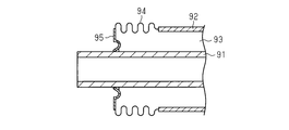
- the metal tube 91 is surrounded by a glass tube 92 to form a double tube structure, and a sealed space (vacuum part) 93 is formed between the metal tube 91 and the glass tube 92, Is prevented from diffusing from the metal pipe 91 into the atmosphere.
- the metal bellows 94 is used as a thermal expansion difference absorbing means for absorbing the difference in thermal expansion between the metal tube 91 and the glass tube 92.
- the metal bellows 94 has one end welded to the glass tube 92 and the other end welded to the flange 95 (see, for example, Patent Document 1).
- the expansion and contraction of the metal bellows 94 absorbs the difference in thermal expansion between the metal tube 91 and the glass tube 92.
- the welded portion between the metal bellows 94 and the flange 95, and the metal bellows 94 When stress is generated in the welded portion between the glass tube 92 and the welded portion is damaged, the degree of vacuum in the sealed space 93 cannot be maintained. For this reason, in the heat collecting tube, it is necessary to improve the durability of the welded portion between the metal bellows 94 and the flange 95 and the welded portion between the metal bellows 94 and the glass tube 92.
- An object of the present invention is to provide a heat collecting tube capable of improving the durability of a welded portion.
- a heat collecting tube for solving the above problems is a metal tube through which a heat medium can flow, a glass tube disposed on the outer peripheral side of the metal tube in a state of forming an annular space between the metal tube, A heat collecting tube having a first flange integral with the metal tube and a metal bellows connected to a second flange integral with the glass tube, wherein the bellows includes the metal tube and the glass tube.
- the bellows is arranged to be in a compressed state that is shorter than the natural length of the bellows in a maximum extension state caused by the difference in thermal expansion of the bellows, and the bellows is an extendable part that expands and contracts between the first flange and the second flange,
- a first welded portion provided at one end of the bellows and welded to the first flange;
- a second welded portion provided at the other end of the bellows and welded to the second flange; 1 weld and the expansion and contraction Provided between the first abutting portion for applying a compressive load to the first flange during expansion and contraction of the expansion and contraction portion, and between the second welded portion and the expansion and contraction portion.
- the gist of the present invention is to have a second contact portion that applies a compressive load to the second flange.
- the bellows in the operating temperature range of the heat collecting tube, the bellows is in a compressed state and is not pulled.
- the compressive load is supported by the first contact portion and the second contact portion, so that the load in the expansion / contraction direction of the expansion / contraction portion is applied to the first welding portion and the second welding portion. Absent.
- the durability of the first welded portion and the second welded portion can be improved.
- the said 1st welding part is provided with the 1st annular protrusion which protruded in the direction which leaves
- the said 1st annular protrusion The first flange is fitted, and the second welded portion includes a second annular protrusion protruding from the second abutting portion in a direction approaching the glass tube along the expansion / contraction direction of the bellows, The second flange may be fitted to the second annular protrusion.
- the weight of the glass tube can be supported by the first flange by fitting the first flange to the first annular protrusion. Further, the weight of the glass tube can be supported by the second flange by fitting the second flange to the second annular protrusion.
- the load directed downward in the vertical direction acting on the first welded portion and the second welded portion is reduced, and the force that shears each welded portion of the bellows from each flange is reduced.
- the durability of the second welded portion can be improved.
- the said 2nd flange is by the collar part provided in the other end of the ring member by which one end was connected to the edge part of the said glass tube, and the cyclic
- the second annular projection may be fitted to the welding member.
- the second welded portion can be easily formed by utilizing the thickness of the welding member, and the second annular protrusion can be easily fitted.
- the durability of the welded portion can be improved.
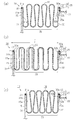
- the fragmentary sectional view which shows the heat collecting tube of embodiment (A) is a fragmentary sectional view which shows the bellows of an unused state, (b) is a fragmentary sectional view which shows the bellows of the maximum extension state, (c) is a fragmentary sectional view which shows the bellows of the maximum contraction state.
- a heat collecting tube (solar heat collecting device) 10 forms a stainless steel tube 11 as a metal tube through which a heat medium can flow and an annular vacuum space 12 as an annular space between the stainless steel tube 11. And a glass tube 21 covering the outer periphery of the stainless steel tube 11 in a state of being.
- the heat collecting tube 10 includes a metal bellows 16 (in this embodiment, stainless steel (SUS)) that absorbs a difference in thermal expansion between the stainless steel tube 11 and the glass tube 21.
- FIG. 1 shows one end side of the heat collecting tube 10 in the axial direction, and the heat collecting tube 10 is configured similarly (symmetrically) on the other end side in the axial direction.
- the stainless steel tube 11 includes a first flange 15 at a position away from the both ends in the axial direction of the glass tube 21 by a predetermined amount.
- the first flange 15 is made of stainless steel (SUS).
- the first flange 15 has an annular shape having a certain width in the radial direction of the stainless steel tube 11.
- the first flange 15 includes a first inner surface 15a on an end surface near the bellows 16 among both end surfaces in the thickness direction. Moreover, the 1st flange 15 has the fitting insertion hole 15b by which the stainless steel tube 11 is inserted by center part.
- the heat collecting tube 10 includes a getter material 19 that adsorbs free hydrogen existing in the annular vacuum space 12.
- a getter holding portion 20 that accommodates and holds the getter material 19 is provided in a state of being located inside the bellows 16.
- the length of the glass tube 21 in the axial direction is shorter than the length of the stainless steel tube 11 in the axial direction.
- the glass tube 21 includes a Kovar ring 22 as a ring member at both axial ends (only one axial end is shown in FIG. 1).
- the Kovar ring 22 is made of Kovar, which is an alloy in which nickel and cobalt are blended with iron, has a low coefficient of thermal expansion among metals, and is close to hard glass.
- the Kovar ring 22 has a cylindrical shape, and the first end 22 a in the axial direction of the Kovar ring 22 is connected to the end of the glass tube 21.
- the Kovar ring 22 includes an annular flange 23 at the second end 22b in the axial direction.
- the flange 23 has a certain width in the radial direction of the Kovar ring 22.
- An annular welding member 24 is joined to the flange portion 23 of the Kovar ring 22 by welding.
- the welding member 24 is made of stainless steel (SUS).
- the outer diameter of the welding member 24 is the same as the outer diameter of the flange 23, and the outer peripheral edge of the welding member 24 is flush with the outer peripheral edge of the flange 23.
- the inner diameter of the welding member 24 is smaller than the inner diameter of the flange 23, and the inner peripheral edge of the welding member 24 is located closer to the stainless steel tube 11 than the inner peripheral edge of the flange 23.
- the second flange 25 is configured by the flange portion 23 and the welding member 24, and the glass tube 21 includes the second flange 25.
- the second flange 25 includes a second inner surface 25 a on an end surface near the bellows 16 among both end surfaces in the thickness direction, and the second inner surface 25 a is formed by an annular end surface of the welding member 24.
- the bellows 16 is a bellows part 30 as an expansion / contraction part, an annular part located at one axial end of the bellows 16, a first contact part 31 continuous with the bellows part 30, and the other axial end of the bellows 16. And a second abutting portion 32 continuous to the bellows portion 30.
- the bellows 16 is provided at one end of the bellows 16 in the axial direction and is welded to the first flange 15.
- the bellows 16 is provided at the other end of the bellows 16 in the axial direction.
- the first contact part 31 is provided between the first welding part 41 and the bellows part 30, and the second contact part 32 is provided between the second welding part 42 and the bellows part 30.
- the first contact portion 31 has a certain width in the radial direction, and the outer diameter of the first contact portion 31 is slightly longer than the outer diameter of the first flange 15.
- the first welding part 41 includes a first annular protrusion 31 a that protrudes from the outer peripheral edge of the first contact part 31.
- the first annular protrusion 31 a protrudes from the first contact portion 31 in the direction away from the bellows portion 30 along the axial direction of the bellows 16. Therefore, the first annular protrusion 31 a protrudes in the direction away from the glass tube 21 along the axial direction of the bellows 16.
- the first welding portion 41 is formed by welding the first annular protrusion 31a and the outer peripheral edge of the first flange 15.
- the first annular protrusion 31 a is in a state of being fitted to the outer peripheral edge of the first flange 15.
- the first contact portion 31 includes a first contact surface 31b on a surface surrounded by the first annular protrusion 31a.
- the first contact surface 31 b is in surface contact with the first inner surface 15 a of the first flange 15.
- the second contact portion 32 of the bellows 16 has a constant width in the radial direction, and the outer diameter of the second contact portion 32 is slightly longer than the outer diameter of the second flange 25.
- the second welding portion 42 includes a second annular protrusion 32 a that protrudes from the outer peripheral edge of the second contact portion 32.
- the second annular protrusion 32 a protrudes from the second contact portion 32 in the direction away from the bellows portion 30 along the axial direction of the bellows 16. Therefore, the second annular protrusion 32 a protrudes in the direction approaching the glass tube 21 along the axial direction of the bellows 16.
- the second welding portion 42 is formed by welding the second annular protrusion 32a and the outer peripheral edge of the welding member 24.
- the second annular protrusion 32 a is in a state of being fitted to the outer peripheral edge of the second flange 25.
- the second contact portion 32 includes a second contact surface 32b on a surface surrounded by the second annular protrusion 32a.
- the second contact surface 32 b is in surface contact with the second inner surface 25 a of the second flange 25.
- the length in the axial direction of the bellows 16 when no load is applied in the axial direction is defined as a natural length L.
- a state in which the length in the axial direction is shorter than the natural length L is defined as a compressed state of the bellows 16, and although not shown, A state in which the length in the axial direction is increased is defined as a tension state of the bellows 16.
- the bellows 16 expands and contracts in accordance with the difference in thermal expansion coefficient between the stainless steel tube 11 and the glass tube 21 (hereinafter referred to as “thermal expansion difference”) in the operating temperature range of the heat collecting tube 10.
- the operating temperature range is a range from an upper limit temperature to a lower limit temperature assumed in an environment where the heat collecting tube 10 is exposed.
- the bellows 16 is in the compressed state in either the maximum extended state or the maximum contracted state, so that the bellows 16 is in the compressed state in the first flange 15 and the second flange 25.
- the first contact surface 31 b of the first contact portion 31 is pressed against the first inner surface 15 a of the first flange 15. Therefore, the first flange 15 is pressed by the bellows 16 in a compressed state, a compressive load is applied to the first flange 15, and the compressive load is supported by the first abutting portion 31.
- the second contact surface 32 b of the second contact portion 32 is pressed against the second inner surface 25 a of the second flange 25. Therefore, the second flange 25 is pressed by the bellows 16 in a compressed state, a compressive load is applied to the second flange 25, and the compressive load is supported by the second contact portion 32.
- the bellows 16 when use temperature rises, the bellows 16 will expand
- the first inner surface 15a of the first flange 15 is pressed by the first contact portion 31 by the restoring force of the bellows 16 to the original shape, and the second inner surface 25a of the second flange 25 is pressed by the second contact portion 32. Is pressed by. Therefore, a compression load is applied to the first contact portion 31 and the second contact portion 32 when the bellows portion 30 of the bellows 16 is expanded and contracted, and the bellows 16 is expanded and contracted to the first weld portion 41 and the second weld portion 42.
- Directional load is not applied.
- a compression load is applied to the first contact portion 31 and the second contact portion 32 when the bellows portion 30 of the bellows 16 is expanded and contracted, and the bellows 16 is expanded and contracted to the first weld portion 41 and the second weld portion 42.
- Directional load is not applied.
- the bellows 16 is in a compressed state in the operating temperature range of the heat collecting tube 10, and does not become a pulled state. Since the compressive load is supported by the first contact portion 31 and the second contact portion 32, the load in the expansion / contraction direction of the bellows portion 30 is not applied to the first weld portion 41 and the second weld portion 42. For this reason, for example, when the bellows 16 is in a stretched state and used in a state where the bellows 16 is stretched between the maximum stretched state and the maximum stretched state, the force to return to the natural length state. That is, no tensile load is applied to the first welded portion 41 and the second welded portion 42. Therefore, durability of the 1st welding part 41 and the 2nd welding part 42 can be improved in bellows 16 in which expansion and contraction is repeated.
- the first contact surface 31 b of the first contact portion 31 is pressed against the first inner surface 15 a of the first flange 15 in a state of surface contact, and the second contact surface 32 b of the second contact portion 32. Is pressed against the second inner surface 25a of the second flange 25 in a state of surface contact. For this reason, the compressive load from the bellows 16 is dispersed, and the load concentration on a part of the first flange 15 and the second flange 25 is suppressed. As a result, the first flange 15 and the second flange 25 can be prevented from being damaged even if the bellows 16 is always in a compressed state.
- the first welding portion 41 is formed by welding the first annular protrusion 31 a to the first flange 15 in a state where the first annular protrusion 31 a of the bellows 16 is fitted to the outer peripheral edge of the first flange 15. Yes.
- the second weld portion 42 is formed by welding the second annular protrusion 32 a to the second flange 25 in a state where the second annular protrusion 32 a of the bellows 16 is fitted to the outer peripheral edge of the second flange 25. . For this reason, the weight of the glass tube 21 can be supported by the first flange 15 and the second flange 25.
- the load (shearing force) on the lower side in the vertical direction acting on the first welded portion 41 and the second welded portion 42 can be reduced. Therefore, the shearing force can be reduced while suppressing the load in the expansion and contraction direction from being applied to the first welded portion 41 and the second welded portion 42, and the durability of the first welded portion 41 and the second welded portion 42 is improved. Can do.
- the second flange 25 is formed by welding a welding member 24 to the flange portion 23 of the Kovar ring 22. For this reason, compared with the case where the 2nd flange 25 is formed only with the collar part 23 of the Kovar ring 22, the 2nd flange 25 can be thickened. Therefore, the second welded portion 42 and the second flange 25 are easily welded, the second annular protrusion 32a is easily fitted, and the weight of the glass tube 21 is easily supported.
- the bellows 16 may not include the first annular protrusion 31 a in the first welding portion 41, and in this case, the first contact surface 31 b of the first contact portion 31 and the first contact surface 31 b A first welded portion 41 that is welded to the outer peripheral edge of the first flange 15 is formed on the outer peripheral edge of the first contact portion 31 in a state where the first inner surface 15a of the first flange 15 is in contact with the first inner surface 15a.
- the bellows 16 may not include the second annular protrusion 32a in the second welding portion 42. In this case, the flange portion 23 constitutes the second flange 25 and the second contact portion 32 has a second shape.
- the second welded portion 42 is formed on the outer peripheral edge of the second contact portion 32 while being in contact with the second contact surface 32b and the second inner surface 25a of the second flange 25.
- the bellows 16 is disposed so as to be in a tension state longer than the natural length L of the bellows 16 in the maximum contracted state due to the difference in thermal expansion between the stainless steel tube 11 and the glass tube 21. ing. That is, the bellows 16 may be disposed between the first flange 15 and the second flange 25 in a pulled state so that the bellows 16 is in a pulled state in either the maximum extended state or the maximum reduced state. Good.
- the flange 23 constitutes the second flange 25.
- the bellows 16 is provided at the bellows portion 30 that expands and contracts between the first flange 15 and the second flange 25 and the one end portion of the bellows 16 and is welded to the first flange 15 as in the above embodiment. It has the 1st welding part 41 and the 2nd welding part 42 which is provided in the other end part of the bellows 16, and is welded with the 2nd flange 25.
- the bellows 16 is provided between the first welded portion 41 and the bellows portion 30, and a first abutting portion 31c that applies a tensile load to the first flange 15 when the bellows portion 30 expands and contracts
- a second abutting portion 32 c is provided between the second welded portion 42 and the bellows portion 30 and applies a tensile load to the second flange 25 when the bellows portion 30 expands and contracts.
- the first contact portion 31 c is in contact with a surface opposite to the first inner surface 15 a in the thickness direction of the first flange 15.
- the second contact portion 32 c is in contact with a surface opposite to the second inner surface 25 a in the thickness direction of the second flange 25.
- the 1st welding part 41 has in the inner periphery of the 1st contact part 31c, and the 2nd welding part 42 has in the inner periphery of the 2nd contact part 32c.
- the bellows 16 is in a tensile state in the operating temperature range of the heat collecting tube 10, and is not in a compressed state. Since the tensile load is supported by the first contact portion 31c and the second contact portion 32c, the load in the expansion / contraction direction of the bellows portion 30 is not applied to the first welding portion 41 and the second welding portion 42. Therefore, durability of the 1st welding part 41 and the 2nd welding part 42 can be improved in bellows 16 in which expansion and contraction is repeated.
- the welding member 24 may not be provided.
- the second annular protrusion 32a is in a state where the second annular protrusion 32a of the second contact portion 32 is fitted to the outer peripheral edge of the flange portion 23. It is welded to the part 23.
- the stainless steel tube 11 and the bellows 16 may be formed of a metal other than stainless steel.
- the annular space is not limited to the annular vacuum space 12, but for example, a gas whose thermal conductivity is smaller than air is filled in the annular space at a pressure equal to or higher than the normal atmospheric pressure, and the thermal conductivity is about the same level as the vacuum. It may be. “Vacuum” means a state of a space filled with a gas having a pressure lower than the normal atmospheric pressure.
- a metal tube through which a heat medium can flow a glass tube disposed on the outer peripheral side of the metal tube in a state where an annular space is formed between the metal tube, and a first flange integrated with the metal tube
- a metal bellows connected to a second flange integral with the glass tube, the bellows having a maximum contraction caused by a difference in thermal expansion between the metal tube and the glass tube
- the bellows is disposed in a tension state that is longer than the natural length of the bellows in a state, and the bellows is provided at an expansion / contraction portion that extends and contracts between the first flange and the second flange, and at one end of the bellows.
- a first welded portion that is welded to the first flange, a second welded portion that is provided at the other end of the bellows and is welded to the second flange, and the first welded portion and the telescopic portion. Provided between them, Sometimes provided between the first contact portion for applying a tensile load to the first flange, the second welded portion, and the expansion / contraction portion, and applying a tensile load to the second flange when the expansion / contraction portion expands / contracts.
- a heat collecting tube comprising: a second contact portion.
- the first contact portion is in contact with a surface opposite to the inner surface near the bellows in the first flange, and the second contact portion is opposite to the inner surface near the bellows in the second flange.
- a heat collection tube in contact with the surface.
Landscapes
- Engineering & Computer Science (AREA)
- Physics & Mathematics (AREA)
- Life Sciences & Earth Sciences (AREA)
- Sustainable Development (AREA)
- Sustainable Energy (AREA)
- Thermal Sciences (AREA)
- Chemical & Material Sciences (AREA)
- Combustion & Propulsion (AREA)
- Mechanical Engineering (AREA)
- General Engineering & Computer Science (AREA)
- Joints Allowing Movement (AREA)
Abstract
集熱管において、ベローズは、ステンレス管とガラス管の熱膨張差に起因した最大伸長状態及び最大縮長状態のいずれの状態でも圧縮状態にある。第1フランジの第1内面に対しベローズの第1当接部が押し当てられ、第2フランジの第2内面に対し第2当接部が押し当てられている。
Description
本発明は、ステンレス管の外周面にフランジ及び金属製のベローズを介してガラス管が支持された集熱管に関する。
熱媒体が流通する金属管を太陽熱で加熱することにより熱媒体を加熱し、その熱を発電や化学反応に利用することが考えられている。集熱管は、金属管が大気に露出した状態にあると、金属管の表面から熱が大気中に拡散してしまうため、金属管の内部を流通する熱媒体を効率良く加熱できないという問題がある。
このため、図5に示すように、金属管91をガラス管92で囲んで二重管構造とし、金属管91とガラス管92との間に密閉空間(真空部)93を形成して、熱が金属管91から大気中に拡散することを防止している。しかしながら、金属管91とガラス管92とは熱膨張率の差が大きいため、金属管91とガラス管92との熱膨張差を吸収する熱膨張差吸収手段として金属ベローズ94が使用されている。金属ベローズ94は、一端がガラス管92に溶接され、他端がフランジ95に溶接されている(例えば、特許文献1参照)。
ところで、金属ベローズ94の伸縮によって金属管91とガラス管92との熱膨張差を吸収しているが、金属ベローズ94の伸縮に伴い、金属ベローズ94とフランジ95との溶接部、及び金属ベローズ94とガラス管92との溶接部には応力が発生し、溶接部が破損すると、密閉空間93の真空度が維持できなくなってしまう。このため、集熱管においては、金属ベローズ94とフランジ95の溶接部、及び金属ベローズ94とガラス管92の溶接部の耐久性の向上が必要である。
本発明の目的は、溶接部の耐久性を向上させることができる集熱管を提供することにある。
上記問題点を解決するための集熱管は、熱媒体が流通可能な金属管と、前記金属管との間に環状空間を形成する状態で前記金属管の外周側に配置されたガラス管と、前記金属管と一体の第1フランジと、前記ガラス管と一体の第2フランジとを接続した金属製のベローズと、を有する集熱管であって、前記ベローズは、前記金属管と前記ガラス管との熱膨張差に起因した最大伸長状態において前記ベローズの自然長より短くなる圧縮状態となるように配設され、前記ベローズは、前記第1フランジと前記第2フランジの間で伸縮する伸縮部と、前記ベローズの一端部に設けられ、前記第1フランジと溶接される第1溶接部と、前記ベローズの他端部に設けられ、前記第2フランジと溶接される第2溶接部と、前記第1溶接部と前記伸縮部との間に設けられ、前記伸縮部の伸縮時に前記第1フランジに圧縮荷重を付与する第1当接部と、前記第2溶接部と前記伸縮部との間に設けられ、前記伸縮部の伸縮時に前記第2フランジに圧縮荷重を付与する第2当接部とを有することを要旨とする。
これによれば、集熱管の使用温度範囲では、ベローズは圧縮状態にあり、引っ張り状態になることがない。そして、集熱管の使用時には、圧縮荷重は、第1当接部及び第2当接部によって支持されるため、伸縮部の伸縮方向の荷重が第1溶接部及び第2溶接部に加わることがない。その結果、第1溶接部及び第2溶接部の耐久性を向上させることができる。
また、集熱管について、前記第1溶接部は、前記第1当接部から前記ベローズの伸縮方向に沿って前記ガラス管から離れる方向へ突出した第1環状突起を備えるとともに、前記第1環状突起に前記第1フランジが嵌合され、前記第2溶接部は、前記第2当接部から前記ベローズの伸縮方向に沿って前記ガラス管に近付く方向へ突出した第2環状突起を備えるとともに、前記第2環状突起に前記第2フランジが嵌合されていてもよい。
これによれば、第1環状突起に第1フランジが嵌合することで、ガラス管の重量を第1フランジで支承できる。また、第2環状突起に第2フランジが嵌合することで、ガラス管の重量を第2フランジで支承できる。その結果、第1溶接部及び第2溶接部に作用する鉛直方向下側に向けた荷重が低減され、ベローズの各溶接部を各フランジからせん断する力が低減される結果、第1溶接部及び第2溶接部の耐久性を向上させることができる。
また、集熱管について、前記第2フランジは、前記ガラス管の端部に一端が接続されたリング部材の他端に設けた鍔部と、該鍔部に接合された環状の溶接部材と、によって構成され、前記第2環状突起は前記溶接部材に嵌合していてもよい。
これによれば、溶接部材の厚みを利用して第2溶接部が形成しやすくなるとともに、第2環状突起を嵌合させやすい。
本発明によれば、溶接部の耐久性を向上させることができる。
以下、集熱管を具体化した一実施形態を図1~図2にしたがって説明する。
図1に示すように、集熱管(太陽熱集熱装置)10は、熱媒体が流通可能な金属管としてのステンレス管11と、ステンレス管11との間に環状空間としての環状真空空間12を形成する状態でステンレス管11の外周を覆うガラス管21と、を有する。また、集熱管10は、ステンレス管11とガラス管21との熱膨張差を吸収する金属製(本実施形態ではステンレス鋼(SUS))のベローズ16を備えている。なお、図1は集熱管10の軸方向一端側を示しており、集熱管10は軸方向他端側も同様(対称)に構成されている。
図1に示すように、集熱管(太陽熱集熱装置)10は、熱媒体が流通可能な金属管としてのステンレス管11と、ステンレス管11との間に環状空間としての環状真空空間12を形成する状態でステンレス管11の外周を覆うガラス管21と、を有する。また、集熱管10は、ステンレス管11とガラス管21との熱膨張差を吸収する金属製(本実施形態ではステンレス鋼(SUS))のベローズ16を備えている。なお、図1は集熱管10の軸方向一端側を示しており、集熱管10は軸方向他端側も同様(対称)に構成されている。
ステンレス管11は、ガラス管21の軸方向両端部から所定量離れた位置に第1フランジ15を備える。第1フランジ15はステンレス鋼(SUS)製である。第1フランジ15は、ステンレス管11の径方向に一定の幅を有する円環状である。
第1フランジ15は、厚み方向の両端面のうちベローズ16寄りの端面に第1内面15aを備える。また、第1フランジ15は、中心部にステンレス管11が嵌挿される嵌挿孔15bを有する。集熱管10は、環状真空空間12に存在する自由水素を吸着するゲッタ材19を備える。ゲッタ材19を収容保持するゲッタ保持部20は、ベローズ16の内側に位置する状態で設けられている。
ガラス管21の軸方向への長さは、ステンレス管11の軸方向への長さより短い。ガラス管21は、軸方向両端(図1では軸方向一端のみ図示)にリング部材としてのコバールリング22を備える。コバールリング22は、鉄にニッケル及びコバルトを配合した合金であるコバール製であり、熱膨張率が金属のなかで低く、硬質ガラスに近い。コバールリング22は円筒状であり、コバールリング22の軸方向の第1端部22aがガラス管21の端部に接続されている。
図2(a)に示すように、コバールリング22は、軸方向の第2端部22bに円環状の鍔部23を備える。鍔部23は、コバールリング22の径方向に一定の幅を有する。コバールリング22の鍔部23には、円環状の溶接部材24が溶接によって接合されている。溶接部材24はステンレス鋼(SUS)製である。溶接部材24の外径は、鍔部23の外径と同じであり、溶接部材24の外周縁は鍔部23の外周縁と面一である。溶接部材24の内径は、鍔部23の内径より小さく、溶接部材24の内周縁は、鍔部23の内周縁よりもステンレス管11寄りに位置している。
鍔部23と溶接部材24とにより、第2フランジ25が構成され、ガラス管21は第2フランジ25を備える。第2フランジ25は、厚み方向の両端面のうちベローズ16寄りの端面に第2内面25aを備え、この第2内面25aは溶接部材24の円環状の端面によって形成されている。
ベローズ16は、伸縮部としての蛇腹部30と、ベローズ16の軸方向一端に位置する円環状の部分であり、蛇腹部30に連続した第1当接部31と、ベローズ16の軸方向他端に位置する円環状の部分であり、蛇腹部30に連続した第2当接部32とを有する。
ベローズ16は、該ベローズ16の軸方向の一端部に設けられ、第1フランジ15と溶接される第1溶接部41と、ベローズ16の軸方向の他端部に設けられ、第2フランジ25と溶接される第2溶接部42とを有する。第1当接部31は、第1溶接部41と蛇腹部30との間に設けられ、第2当接部32は、第2溶接部42と蛇腹部30との間に設けられる。
第1当接部31は、径方向に一定の幅を有し、第1当接部31の外径は、第1フランジ15の外径より僅かに長い。第1溶接部41は、第1当接部31の外周縁から突出する第1環状突起31aを備える。第1環状突起31aは、ベローズ16の軸方向に沿って蛇腹部30から離れる方向へ第1当接部31から突出する。よって、第1環状突起31aは、ベローズ16の軸方向に沿ってガラス管21から離れる方向へ突出する。
第1溶接部41は、第1環状突起31aと第1フランジ15の外周縁とを溶接して形成されている。第1環状突起31aは、第1フランジ15の外周縁に嵌合した状態にある。第1当接部31は、第1環状突起31aで囲まれた面に第1当接面31bを備える。この第1当接面31bは、第1フランジ15の第1内面15aに面接触している。
ベローズ16の第2当接部32は、径方向に一定の幅を有し、第2当接部32の外径は、第2フランジ25の外径より僅かに長い。第2溶接部42は、第2当接部32の外周縁から突出する第2環状突起32aを備える。第2環状突起32aは、ベローズ16の軸方向に沿って蛇腹部30から離れる方向へ第2当接部32から突出する。よって、第2環状突起32aは、ベローズ16の軸方向に沿ってガラス管21に近付く方向へ突出する。
第2溶接部42は、第2環状突起32aと溶接部材24の外周縁とを溶接して形成されている。第2環状突起32aは第2フランジ25の外周縁に嵌合した状態にある。第2当接部32は、第2環状突起32aで囲まれた面に第2当接面32bを備える。この第2当接面32bは、第2フランジ25の第2内面25aに面接触している。
ここで、図2(b)の2点鎖線に示すように、ベローズ16において、軸方向に負荷が掛かっていない状態での軸方向への長さを自然長Lとする。図2(a)~図2(c)に示すように、自然長Lよりも軸方向への長さが短くなった状態をベローズ16の圧縮状態とし、図示はしないが、自然長Lよりも軸方向への長さが長くなった状態をベローズ16の引っ張り状態とする。
ベローズ16は、集熱管10の使用温度範囲において、ステンレス管11とガラス管21の熱膨張率の差(以下、熱膨張差と記載する)に応じて伸縮する。なお、使用温度範囲とは、集熱管10が曝される環境下において想定される上限温度から下限温度までの範囲である。
使用温度範囲において、図2(b)に示すように、使用温度範囲の上限温度でベローズ16の軸方向への長さが最も長くなったときを最大伸長状態とし、図2(c)に示すように、下限温度でベローズ16の軸方向への長さが最も短くなったときを最大縮長状態とする。
図2(a)に示すように、ベローズ16は、最大伸長状態及び最大縮長状態のいずれの状態でも圧縮状態にあるように、ベローズ16は、圧縮状態で第1フランジ15と第2フランジ25の間に配設されている。このため、第1当接部31の第1当接面31bは、第1フランジ15の第1内面15aに押し当てられている。よって、第1フランジ15は圧縮状態のベローズ16によって押圧され、第1フランジ15には圧縮荷重が付与されているとともに、その圧縮荷重は第1当接部31に支持されている。また、第2当接部32の第2当接面32bは、第2フランジ25の第2内面25aに押し当てられている。よって、第2フランジ25は圧縮状態のベローズ16によって押圧され、第2フランジ25には圧縮荷重が付与されているとともに、その圧縮荷重は第2当接部32に支持されている。
次に、集熱管10の作用を記載する。
さて、図2(b)に示すように、使用温度が上昇すると、ステンレス管11とガラス管21との熱膨張差により、ベローズ16は伸長し、使用温度が上限温度に達し、最大伸長状態まで変位してもベローズ16は圧縮状態である。すなわち、ベローズ16は、ステンレス管11とガラス管21の熱膨張差に起因した最大伸長状態にてベローズ16の自然長Lより短くなる圧縮状態となるように配設されている。
さて、図2(b)に示すように、使用温度が上昇すると、ステンレス管11とガラス管21との熱膨張差により、ベローズ16は伸長し、使用温度が上限温度に達し、最大伸長状態まで変位してもベローズ16は圧縮状態である。すなわち、ベローズ16は、ステンレス管11とガラス管21の熱膨張差に起因した最大伸長状態にてベローズ16の自然長Lより短くなる圧縮状態となるように配設されている。
このため、ベローズ16の原形状への復帰力により、第1フランジ15の第1内面15aが第1当接部31によって押圧され、第2フランジ25の第2内面25aが第2当接部32によって押圧される。このため、ベローズ16の蛇腹部30の伸縮時に第1当接部31及び第2当接部32には圧縮荷重が付与され、第1溶接部41及び第2溶接部42にはベローズ16の伸縮方向の荷重は加わらない。
一方、図2(c)に示すように、使用温度が下降すると、ステンレス管11とガラス管21との熱膨張差により、ベローズ16は収縮し、使用温度が下限温度に達し、最大縮長状態にまで変位してもベローズ16は圧縮状態にある。このため、ベローズ16の原形状への復帰力により、第1フランジ15の第1内面15aが第1当接部31によって押圧され、第2フランジ25の第2内面25aが第2当接部32によって押圧される。このため、ベローズ16の蛇腹部30の伸縮時に第1当接部31及び第2当接部32には圧縮荷重が付与され、第1溶接部41及び第2溶接部42にはベローズ16の伸縮方向の荷重は加わらない。
上記実施形態によれば、以下のような効果を得ることができる。
(1)ベローズ16は、集熱管10の使用温度範囲では圧縮状態にあり、引っ張り状態となることがない。圧縮荷重は、第1当接部31及び第2当接部32によって支持されるため、蛇腹部30の伸縮方向の荷重が第1溶接部41及び第2溶接部42に加わることがない。このため、例えば、ベローズ16が、自然長にある状態を、最大伸長状態と最大縮長状態で跨いで使用されている場合のように、伸長状態にあるときには自然長の状態に戻ろうとする力、すなわち、引っ張り荷重が第1溶接部41及び第2溶接部42に加わることがない。よって、伸縮が繰り返されるベローズ16において、第1溶接部41及び第2溶接部42の耐久性を向上させることができる。
(1)ベローズ16は、集熱管10の使用温度範囲では圧縮状態にあり、引っ張り状態となることがない。圧縮荷重は、第1当接部31及び第2当接部32によって支持されるため、蛇腹部30の伸縮方向の荷重が第1溶接部41及び第2溶接部42に加わることがない。このため、例えば、ベローズ16が、自然長にある状態を、最大伸長状態と最大縮長状態で跨いで使用されている場合のように、伸長状態にあるときには自然長の状態に戻ろうとする力、すなわち、引っ張り荷重が第1溶接部41及び第2溶接部42に加わることがない。よって、伸縮が繰り返されるベローズ16において、第1溶接部41及び第2溶接部42の耐久性を向上させることができる。
(2)第1当接部31の第1当接面31bは、第1フランジ15の第1内面15aに面接触した状態で押し当てられ、第2当接部32の第2当接面32bは、第2フランジ25の第2内面25aに面接触した状態で押し当てられている。このため、ベローズ16からの圧縮荷重は分散され、第1フランジ15及び第2フランジ25の一部に荷重集中することが抑制される。その結果として、ベローズ16が常に圧縮状態にあっても第1フランジ15及び第2フランジ25が損傷することを抑制できる。
(3)第1溶接部41は、ベローズ16の第1環状突起31aが第1フランジ15の外周縁に嵌合した状態で、第1環状突起31aを第1フランジ15に溶接して形成されている。また、第2溶接部42は、ベローズ16の第2環状突起32aが第2フランジ25の外周縁に嵌合した状態で、第2環状突起32aを第2フランジ25に溶接して形成されている。このため、ガラス管21の重量を第1フランジ15及び第2フランジ25に支承させることができる。よって、第1溶接部41及び第2溶接部42に作用する鉛直方向下側への荷重(せん断力)を低減できる。したがって、第1溶接部41及び第2溶接部42に伸縮方向への荷重が加わるのを抑制しつつ、せん断力も低減でき、第1溶接部41及び第2溶接部42の耐久性を向上させることができる。
(4)第2フランジ25は、コバールリング22の鍔部23に溶接部材24を溶接して形成されている。このため、コバールリング22の鍔部23だけで第2フランジ25を形成する場合と比べると、第2フランジ25を厚くできる。よって、第2溶接部42と第2フランジ25との溶接が行いやすく、また、第2環状突起32aを嵌合させやすく、ガラス管21の重量を支承しやすい。
なお、上記実施形態は以下のように変更してもよい。
○ 図3に示すように、ベローズ16は、第1溶接部41に第1環状突起31aを備えていなくてもよく、この場合は、第1当接部31の第1当接面31bと第1フランジ15の第1内面15aとを当接させた状態で第1当接部31の外周縁に第1フランジ15の外周縁と溶接する第1溶接部41が形成される。また、ベローズ16は、第2溶接部42に第2環状突起32aを備えていなくてもよく、この場合は、鍔部23が第2フランジ25を構成するとともに、第2当接部32の第2当接面32bと第2フランジ25の第2内面25aと当接させた状態で第2当接部32の外周縁に第2フランジ25の外周縁と溶接する第2溶接部42が形成される。なお、上記のように環状突起を備えない構成は、第1溶接部41及び第2溶接部42のいずれか一方であってもよい。
○ 図3に示すように、ベローズ16は、第1溶接部41に第1環状突起31aを備えていなくてもよく、この場合は、第1当接部31の第1当接面31bと第1フランジ15の第1内面15aとを当接させた状態で第1当接部31の外周縁に第1フランジ15の外周縁と溶接する第1溶接部41が形成される。また、ベローズ16は、第2溶接部42に第2環状突起32aを備えていなくてもよく、この場合は、鍔部23が第2フランジ25を構成するとともに、第2当接部32の第2当接面32bと第2フランジ25の第2内面25aと当接させた状態で第2当接部32の外周縁に第2フランジ25の外周縁と溶接する第2溶接部42が形成される。なお、上記のように環状突起を備えない構成は、第1溶接部41及び第2溶接部42のいずれか一方であってもよい。
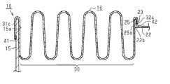
○ 図4に示すように、ベローズ16は、ステンレス管11とガラス管21との熱膨張差に起因した最大縮長状態においてベローズ16の自然長Lより長くなる引っ張り状態となるように配設されている。すなわち、ベローズ16は、最大伸長状態及び最大縮長状態のいずれの状態でも引っ張り状態にあるように、引っ張られた状態で第1フランジ15と第2フランジ25との間に配設されていてもよい。なお、鍔部23が第2フランジ25を構成する。
この場合、ベローズ16は、上記実施形態と同様に第1フランジ15と第2フランジ25との間で伸縮する蛇腹部30と、ベローズ16の一端部に設けられ、第1フランジ15と溶接される第1溶接部41と、ベローズ16の他端部に設けられ、第2フランジ25と溶接される第2溶接部42と、を有する。上記実施形態と異なり、ベローズ16は、第1溶接部41と蛇腹部30との間に設けられ、蛇腹部30の伸縮時に第1フランジ15に引っ張り荷重を付与する第1当接部31cと、第2溶接部42と蛇腹部30との間に設けられ、蛇腹部30の伸縮時に第2フランジ25に引っ張り荷重を付与する第2当接部32cとを有する。
第1当接部31cは、第1フランジ15の厚み方向における第1内面15aとは反対の面に当接している。また、第2当接部32cは、第2フランジ25の厚み方向における第2内面25aとは反対の面に当接している。第1溶接部41は、第1当接部31cの内周に有し、第2溶接部42は、第2当接部32cの内周に有する。
この場合、ベローズ16は、集熱管10の使用温度範囲では引っ張り状態にあり、圧縮状態となることがない。引っ張り荷重は、第1当接部31c及び第2当接部32cによって支持されるため、蛇腹部30の伸縮方向の荷重が第1溶接部41及び第2溶接部42に加わることがない。よって、伸縮が繰り返されるベローズ16において、第1溶接部41及び第2溶接部42の耐久性を向上させることができる。
○ 実施形態において、溶接部材24は無くてもよく、この場合、第2当接部32の第2環状突起32aを鍔部23の外周縁に嵌合させた状態で第2環状突起32aが鍔部23に溶接される。
○ ステンレス管11やベローズ16をステンレス鋼以外の金属で形成してもよい。
○ 環状空間は環状真空空間12に限らず、例えば、熱伝導率が空気より小さい気体が環状空間に通常の大気圧と同等以上の圧力で満たされて、熱伝導率が真空と同程度の状態であってもよい。なお、「真空」とは、通常の大気圧より低い圧力の気体で満たされた空間の状態を意味する。
○ 環状空間は環状真空空間12に限らず、例えば、熱伝導率が空気より小さい気体が環状空間に通常の大気圧と同等以上の圧力で満たされて、熱伝導率が真空と同程度の状態であってもよい。なお、「真空」とは、通常の大気圧より低い圧力の気体で満たされた空間の状態を意味する。
次に、上記実施形態及び別例から把握できる技術的思想について以下に追記する。
(1)熱媒体が流通可能な金属管と、前記金属管との間に環状空間を形成する状態で前記金属管の外周側に配置されたガラス管と、前記金属管と一体の第1フランジと、前記ガラス管と一体の第2フランジとを接続した金属製のベローズと、を有する集熱管であって、前記ベローズは、前記金属管と前記ガラス管の熱膨張差に起因した最大縮長状態において前記ベローズの自然長より長くなる引っ張り状態となるように配設され、前記ベローズは、前記第1フランジと前記第2フランジの間で伸縮する伸縮部と、前記ベローズの一端部に設けられ、前記第1フランジと溶接される第1溶接部と、前記ベローズの他端部に設けられ、前記第2フランジと溶接される第2溶接部と、前記第1溶接部と前記伸縮部との間に設けられ、前記伸縮部の伸縮時に前記第1フランジに引っ張り荷重を付与する第1当接部と、前記第2溶接部と前記伸縮部との間に設けられ、前記伸縮部の伸縮時に前記第2フランジに引っ張り荷重を付与する第2当接部とを有することを特徴とする集熱管。
(1)熱媒体が流通可能な金属管と、前記金属管との間に環状空間を形成する状態で前記金属管の外周側に配置されたガラス管と、前記金属管と一体の第1フランジと、前記ガラス管と一体の第2フランジとを接続した金属製のベローズと、を有する集熱管であって、前記ベローズは、前記金属管と前記ガラス管の熱膨張差に起因した最大縮長状態において前記ベローズの自然長より長くなる引っ張り状態となるように配設され、前記ベローズは、前記第1フランジと前記第2フランジの間で伸縮する伸縮部と、前記ベローズの一端部に設けられ、前記第1フランジと溶接される第1溶接部と、前記ベローズの他端部に設けられ、前記第2フランジと溶接される第2溶接部と、前記第1溶接部と前記伸縮部との間に設けられ、前記伸縮部の伸縮時に前記第1フランジに引っ張り荷重を付与する第1当接部と、前記第2溶接部と前記伸縮部との間に設けられ、前記伸縮部の伸縮時に前記第2フランジに引っ張り荷重を付与する第2当接部とを有することを特徴とする集熱管。
(2)前記第1当接部は、前記第1フランジにおいて前記ベローズ寄りの内面とは反対面に当接し、前記第2当接部は、前記第2フランジにおいて前記ベローズ寄りの内面とは反対面に当接している集熱管。
10 集熱管
11 金属管としてのステンレス管
13 環状空間としての環状真空空間
15 第1フランジ
16 ベローズ
17 リング部材としてのコバールリング
21 ガラス管
23 鍔部
24 溶接部材
25 第2フランジ
30 伸縮部としての蛇腹部
31,31c 第1当接部
31a 第1環状突起
32,32c 第2当接部
32a 第2環状突起
41 第1溶接部
42 第2溶接部
11 金属管としてのステンレス管
13 環状空間としての環状真空空間
15 第1フランジ
16 ベローズ
17 リング部材としてのコバールリング
21 ガラス管
23 鍔部
24 溶接部材
25 第2フランジ
30 伸縮部としての蛇腹部
31,31c 第1当接部
31a 第1環状突起
32,32c 第2当接部
32a 第2環状突起
41 第1溶接部
42 第2溶接部
Claims (5)
- 熱媒体が流通可能な金属管と、
前記金属管との間に環状空間を形成する状態で前記金属管の外周側に配置されたガラス管と、
前記金属管と一体の第1フランジと、前記ガラス管と一体の第2フランジとを接続した金属製のベローズと、を有する集熱管であって、
前記ベローズは、前記金属管と前記ガラス管との熱膨張差に起因した最大伸長状態において前記ベローズの自然長より短くなる圧縮状態となるように配設され、
前記ベローズは、
前記第1フランジと前記第2フランジの間で伸縮する伸縮部と、
前記ベローズの一端部に設けられ、前記第1フランジと溶接される第1溶接部と、
前記ベローズの他端部に設けられ、前記第2フランジと溶接される第2溶接部と、
前記第1溶接部と前記伸縮部との間に設けられ、前記伸縮部の伸縮時に前記第1フランジに圧縮荷重を付与する第1当接部と、
前記第2溶接部と前記伸縮部との間に設けられ、前記伸縮部の伸縮時に前記第2フランジに圧縮荷重を付与する第2当接部とを有することを特徴とする集熱管。 - 前記第1溶接部は、前記第1当接部から前記ベローズの伸縮方向に沿って前記ガラス管から離れる方向へ突出した第1環状突起を備えるとともに、前記第1環状突起に前記第1フランジが嵌合され、前記第2溶接部は、前記第2当接部から前記ベローズの伸縮方向に沿って前記ガラス管に近付く方向へ突出した第2環状突起を備えるとともに、前記第2環状突起に前記第2フランジが嵌合されている請求項1に記載の集熱管。
- 前記第2フランジは、前記ガラス管の端部に一端が接続されたリング部材の他端に設けた鍔部と、該鍔部に接合された環状の溶接部材と、によって構成され、前記第2環状突起は前記溶接部材に嵌合している請求項2に記載の集熱管。
- 熱媒体が流通可能な金属管と、
前記金属管との間に環状空間を形成する状態で前記金属管の外周側に配置されたガラス管と、
前記金属管と一体の第1フランジと、前記ガラス管と一体の第2フランジとを接続した金属製のベローズと、を有する集熱管であって、
前記ベローズは、前記金属管と前記ガラス管の熱膨張差に起因した最大縮長状態において前記ベローズの自然長より長くなる引っ張り状態となるように配設され、
前記ベローズは、
前記第1フランジと前記第2フランジの間で伸縮する伸縮部と、
前記ベローズの一端部に設けられ、前記第1フランジと溶接される第1溶接部と、
前記ベローズの他端部に設けられ、前記第2フランジと溶接される第2溶接部と、
前記第1溶接部と前記伸縮部との間に設けられ、前記伸縮部の伸縮時に前記第1フランジに引っ張り荷重を付与する第1当接部と、
前記第2溶接部と前記伸縮部との間に設けられ、前記伸縮部の伸縮時に前記第2フランジに引っ張り荷重を付与する第2当接部とを有することを特徴とする集熱管。 - 前記第1当接部は、前記第1フランジにおいて前記ベローズ寄りの内面とは反対面に当接し、
前記第2当接部は、前記第2フランジにおいて前記ベローズ寄りの内面とは反対面に当接している請求項4に記載の集熱管。
Applications Claiming Priority (2)
| Application Number | Priority Date | Filing Date | Title |
|---|---|---|---|
| JP2017-073668 | 2017-04-03 | ||
| JP2017073668A JP2018179306A (ja) | 2017-04-03 | 2017-04-03 | 集熱管 |
Publications (1)
| Publication Number | Publication Date |
|---|---|
| WO2018186085A1 true WO2018186085A1 (ja) | 2018-10-11 |
Family
ID=63713498
Family Applications (1)
| Application Number | Title | Priority Date | Filing Date |
|---|---|---|---|
| PCT/JP2018/008365 Ceased WO2018186085A1 (ja) | 2017-04-03 | 2018-03-05 | 集熱管 |
Country Status (2)
| Country | Link |
|---|---|
| JP (1) | JP2018179306A (ja) |
| WO (1) | WO2018186085A1 (ja) |
Citations (5)
| Publication number | Priority date | Publication date | Assignee | Title |
|---|---|---|---|---|
| JPS61107051A (ja) * | 1984-10-31 | 1986-05-24 | Agency Of Ind Science & Technol | 太陽エネルギ−集熱管 |
| JP2012122693A (ja) * | 2010-12-09 | 2012-06-28 | Hitachi Plant Technologies Ltd | 太陽光集光集熱レシーバ |
| US20120186576A1 (en) * | 2009-09-29 | 2012-07-26 | Schott Solar Ag | Absorber pipe |
| WO2013178370A2 (en) * | 2012-06-01 | 2013-12-05 | Siemens Aktiengesellschaft | Solar reciver tube wit low emissivity covering, method for manufacturing the solar receiver tube and use of the tube |
| JP2015014444A (ja) * | 2013-07-08 | 2015-01-22 | 株式会社豊田自動織機 | 集熱管 |
-
2017
- 2017-04-03 JP JP2017073668A patent/JP2018179306A/ja active Pending
-
2018
- 2018-03-05 WO PCT/JP2018/008365 patent/WO2018186085A1/ja not_active Ceased
Patent Citations (5)
| Publication number | Priority date | Publication date | Assignee | Title |
|---|---|---|---|---|
| JPS61107051A (ja) * | 1984-10-31 | 1986-05-24 | Agency Of Ind Science & Technol | 太陽エネルギ−集熱管 |
| US20120186576A1 (en) * | 2009-09-29 | 2012-07-26 | Schott Solar Ag | Absorber pipe |
| JP2012122693A (ja) * | 2010-12-09 | 2012-06-28 | Hitachi Plant Technologies Ltd | 太陽光集光集熱レシーバ |
| WO2013178370A2 (en) * | 2012-06-01 | 2013-12-05 | Siemens Aktiengesellschaft | Solar reciver tube wit low emissivity covering, method for manufacturing the solar receiver tube and use of the tube |
| JP2015014444A (ja) * | 2013-07-08 | 2015-01-22 | 株式会社豊田自動織機 | 集熱管 |
Also Published As
| Publication number | Publication date |
|---|---|
| JP2018179306A (ja) | 2018-11-15 |
Similar Documents
| Publication | Publication Date | Title |
|---|---|---|
| US9903612B2 (en) | Solar heat collection tube | |
| CN106164602B (zh) | 太阳能聚热装置的制造方法 | |
| US12078283B2 (en) | Thermally insulated transfer line with coupling element | |
| US11333289B2 (en) | Decompression heat-insulating pipe structure | |
| EP2868996A1 (en) | Solar-heat collection tube | |
| CN105782445A (zh) | 一种高压缩高回弹径向密封组件 | |
| CN104358874B (zh) | 一种高压缩高回弹密封组件 | |
| JP2018179306A (ja) | 集熱管 | |
| JP2016008663A (ja) | 断熱多重管及びその製造方法 | |
| US10443776B2 (en) | Decompression heat-insulating pipe structure | |
| US20060260786A1 (en) | Composite wick structure of heat pipe | |
| JP2008275117A (ja) | 耐熱ガス配管構造 | |
| JP5801009B1 (ja) | 二重封止型ターミナルヘッダ | |
| CN205001767U (zh) | 一体化真空传输管 | |
| KR20110130871A (ko) | 메탈 개스킷 | |
| JP2018080779A (ja) | 真空断熱構造体 | |
| CN219571605U (zh) | 一种气体存储罐体连接密封件结构 | |
| CN207935425U (zh) | 一种密封圈和密封结构 | |
| JP6248692B2 (ja) | シール機構 | |
| CN215410683U (zh) | 一种液体火箭管路的连接结构 | |
| JP2005325949A (ja) | 管継手 | |
| CN109297306B (zh) | 具有双隔热壁结构的加热炉 | |
| JP2008275118A (ja) | 熱伸縮対応のガス配管構造 | |
| JP6624391B2 (ja) | 真空断熱二重管構造体 | |
| JP2019001485A (ja) | 加熱炉用断熱壁体 |
Legal Events
| Date | Code | Title | Description |
|---|---|---|---|
| 121 | Ep: the epo has been informed by wipo that ep was designated in this application |
Ref document number: 18781000 Country of ref document: EP Kind code of ref document: A1 |
|
| NENP | Non-entry into the national phase |
Ref country code: DE |
|
| 122 | Ep: pct application non-entry in european phase |
Ref document number: 18781000 Country of ref document: EP Kind code of ref document: A1 |