WO2018186043A1 - 給湯装置、二元温水生成ユニット - Google Patents
給湯装置、二元温水生成ユニット Download PDFInfo
- Publication number
- WO2018186043A1 WO2018186043A1 PCT/JP2018/006505 JP2018006505W WO2018186043A1 WO 2018186043 A1 WO2018186043 A1 WO 2018186043A1 JP 2018006505 W JP2018006505 W JP 2018006505W WO 2018186043 A1 WO2018186043 A1 WO 2018186043A1
- Authority
- WO
- WIPO (PCT)
- Prior art keywords
- hot water
- water supply
- heat exchanger
- refrigerant
- hot
- Prior art date
Links
Images


Classifications
-
- F—MECHANICAL ENGINEERING; LIGHTING; HEATING; WEAPONS; BLASTING
- F24—HEATING; RANGES; VENTILATING
- F24H—FLUID HEATERS, e.g. WATER OR AIR HEATERS, HAVING HEAT-GENERATING MEANS, e.g. HEAT PUMPS, IN GENERAL
- F24H4/00—Fluid heaters characterised by the use of heat pumps
- F24H4/02—Water heaters
-
- F—MECHANICAL ENGINEERING; LIGHTING; HEATING; WEAPONS; BLASTING
- F25—REFRIGERATION OR COOLING; COMBINED HEATING AND REFRIGERATION SYSTEMS; HEAT PUMP SYSTEMS; MANUFACTURE OR STORAGE OF ICE; LIQUEFACTION SOLIDIFICATION OF GASES
- F25B—REFRIGERATION MACHINES, PLANTS OR SYSTEMS; COMBINED HEATING AND REFRIGERATION SYSTEMS; HEAT PUMP SYSTEMS
- F25B1/00—Compression machines, plants or systems with non-reversible cycle
-
- F—MECHANICAL ENGINEERING; LIGHTING; HEATING; WEAPONS; BLASTING
- F25—REFRIGERATION OR COOLING; COMBINED HEATING AND REFRIGERATION SYSTEMS; HEAT PUMP SYSTEMS; MANUFACTURE OR STORAGE OF ICE; LIQUEFACTION SOLIDIFICATION OF GASES
- F25B—REFRIGERATION MACHINES, PLANTS OR SYSTEMS; COMBINED HEATING AND REFRIGERATION SYSTEMS; HEAT PUMP SYSTEMS
- F25B29/00—Combined heating and refrigeration systems, e.g. operating alternately or simultaneously
-
- F—MECHANICAL ENGINEERING; LIGHTING; HEATING; WEAPONS; BLASTING
- F25—REFRIGERATION OR COOLING; COMBINED HEATING AND REFRIGERATION SYSTEMS; HEAT PUMP SYSTEMS; MANUFACTURE OR STORAGE OF ICE; LIQUEFACTION SOLIDIFICATION OF GASES
- F25B—REFRIGERATION MACHINES, PLANTS OR SYSTEMS; COMBINED HEATING AND REFRIGERATION SYSTEMS; HEAT PUMP SYSTEMS
- F25B7/00—Compression machines, plants or systems, with cascade operation, i.e. with two or more circuits, the heat from the condenser of one circuit being absorbed by the evaporator of the next circuit
-
- Y—GENERAL TAGGING OF NEW TECHNOLOGICAL DEVELOPMENTS; GENERAL TAGGING OF CROSS-SECTIONAL TECHNOLOGIES SPANNING OVER SEVERAL SECTIONS OF THE IPC; TECHNICAL SUBJECTS COVERED BY FORMER USPC CROSS-REFERENCE ART COLLECTIONS [XRACs] AND DIGESTS
- Y02—TECHNOLOGIES OR APPLICATIONS FOR MITIGATION OR ADAPTATION AGAINST CLIMATE CHANGE
- Y02B—CLIMATE CHANGE MITIGATION TECHNOLOGIES RELATED TO BUILDINGS, e.g. HOUSING, HOUSE APPLIANCES OR RELATED END-USER APPLICATIONS
- Y02B30/00—Energy efficient heating, ventilation or air conditioning [HVAC]
- Y02B30/12—Hot water central heating systems using heat pumps
Definitions
- the present invention relates to an air-conditioning hot water generator that can supply hot and cold heat necessary for cooling, heating, and hot water supply at the same time, equipped with a hot water generating unit that generates hot water for hot water supply, and an air conditioning refrigerant and a hot water supply refrigerant via a cascade heat exchanger. It is related with the hot-water supply apparatus and binary hot water production
- a hot water supply device that generates hot water and stores it in a hot water storage tank and uses it for hot water supply, it has a refrigerant circuit through which refrigerant circulates and a water circuit through which water circulates, and the refrigerant circuit includes a compressor, a heat exchanger for generating hot water, There is a single-stage heat pump cycle in which an expansion valve and a heat source side heat exchanger are connected. Furthermore, in order to improve the operating efficiency of the hot water supply apparatus, a binary hot water generating unit that is thermally connected to an air conditioning cycle has been proposed (see Patent Document 1).
- FIG. 6 shows a refrigeration cycle configuration diagram of the binary hot water generating unit described in Patent Document 1.
- an air conditioning compressor 11 and an outdoor heat exchanger 12 are sequentially connected and are filled with an air conditioning refrigerant.
- the indoor unit 20 has an indoor heat exchanger 21 and a third refrigerant flow rate adjustment valve 22 connected in order.
- the hot water generation unit 30 is connected to a hot water supply compressor 31, a hot water supply heat exchanger 32, a first refrigerant flow rate adjustment valve 33, and a cascade heat exchanger 34 in that order, and is filled with hot water supply refrigerant.
- a second refrigerant flow rate adjustment valve 41, a cascade heat exchanger 34, and a heat transfer unit gas pipe opening / closing valve 42 are sequentially connected.
- the outdoor unit 10, the indoor unit 20, the hot water generation unit 30, and the heat transfer unit 40 are binary hot water generation units, and the indoor unit 20 and the heat transfer unit 40 are connected to the outdoor unit 10.
- the hot water generation unit 30 and the heat transfer unit 40 are connected in parallel so that the air conditioning refrigerant and the hot water supply refrigerant can exchange heat by the cascade heat exchanger 34.
- the exchanger 32 is configured such that heat of the hot water supply hot water circuit and the hot water supply refrigerant can be exchanged.
- the hot water supply refrigeration cycle can perform a so-called hot water supply operation in which heat is extracted from the heated air conditioning refrigerant to generate high-temperature hot water.
- a plurality of load-side units are connected to one outdoor unit 100 to enable both an air conditioning operation and a hot water supply operation.
- the present invention solves the above-mentioned problem, and in the heating and hot water supply simultaneous operation, when the amount of heat of the air conditioning refrigerant supplied to the cascade heat exchanger increases or decreases with the increase or decrease in the number of heating operations of the indoor units, It aims at suppressing the destabilization of the suction superheat degree of the compressor for hot water supply.
- a hot water supply apparatus of the present invention is a hot water supply apparatus connected to an air conditioner, and includes a hot water generation unit and a heat transfer unit connected to the air conditioner.
- the hot water generating unit uses a CO2 refrigerant as a hot water supply refrigerant, and a high pressure refrigerant at the outlet of the hot water supply and a low pressure refrigerant at the outlet of the cascade heat exchanger.
- An internal heat exchanger capable of heat exchange is further provided.
- the cascade heat exchanger inlet temperature (on the hot water supply refrigerant side) when the high-pressure refrigerant discharged from the hot water supply heat exchanger is expanded to the saturated liquid state is enthalpy-expanded is lower than the hot water supply heat exchanger outlet temperature. It becomes.
- the temperature of the cascade heat exchanger outlet ( Since the hot water supply refrigerant side) is lower than the outlet temperature of the hot water supply heat exchanger, the hot water supply refrigerant from the cascade heat exchanger in the internal heat exchanger absorbs heat from the hot water supply refrigerant output from the hot water supply heat exchanger. .
- the hot water supply refrigerant that has been discharged from the hot water supply heat exchanger dissipates heat in the internal heat exchanger and is then enthalpy-expanded by the expansion valve and enters the cascade heat exchanger in the supercooled liquid state, the inside of the cascade heat exchanger
- the average temperature of the hot water supply refrigerant decreases, and the amount of heat absorbed from the air conditioning refrigerant in the cascade heat exchanger increases.
- the degree of superheat can be obtained by absorbing heat from the hot water supply refrigerant discharged from the hot water supply heat exchanger.
- the hot water supplied from the cascade heat exchanger Since the refrigerant temperature is higher than the refrigerant temperature from the hot water supply heat exchanger, the internal heat exchanger radiates heat to the hot water supply refrigerant from the hot water supply heat exchanger.
- the hot water supply refrigerant that has come out of the hot water supply heat exchanger absorbs heat in the internal heat exchanger and then enters the cascade heat exchanger in a gas-liquid two-phase state with a high degree of dryness by isoenthalpy expansion by the expansion valve,
- the average temperature of the hot water supply refrigerant in the cascade heat exchanger increases, and the amount of heat absorbed from the air conditioning refrigerant in the cascade heat exchanger decreases. Thereafter, in the internal heat exchanger, the degree of superheat is reduced by dissipating heat to the hot water supply refrigerant discharged from the hot water supply heat exchanger.
- the suction overheating of the hot water supply compressor In the hot water supply apparatus of the present invention, in the simultaneous heating and hot water supply operation, when the amount of heat of the air conditioning refrigerant supplied to the cascade heat exchanger increases or decreases with the increase or decrease in the number of indoor unit heating operations, the suction overheating of the hot water supply compressor The degree stabilizes. Therefore, it is possible to suppress the deterioration of the organic material constituting the compressor by the compressor discharge temperature exceeding the upper limit of the compressor use range due to the excessive increase in the suction superheat degree of the hot water supply compressor. Since it is possible to suppress the occurrence of liquid back in the compressor and the wear of the sliding material being promoted without being reduced, the reliability of the hot water supply compressor is improved.
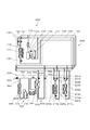
- FIG. 1 is a configuration diagram of a refrigeration cycle of a binary hot water generation unit according to Embodiment 1 of the present invention.
- FIG. 2 is a Mollier chart (hot water supply side) during simultaneous operation of heating (one unit) and hot water supply in Embodiment 1 of the present invention.
- FIG. 3 is a Moliere diagram (hot water supply side) when the number of heating operation increases in Embodiment 1 of the present invention.
- FIG. 4 is a Mollier chart (hot water supply side) when the number of heating operations in the first embodiment of the present invention is reduced.
- FIG. 5 is a configuration diagram of a refrigeration cycle of a binary hot water generation unit according to Embodiment 2 of the present invention.
- FIG. 6 is a configuration diagram of a refrigeration cycle of the binary hot water generation unit described in Patent Document 1.
- 1st invention is a hot-water supply apparatus connected to an air conditioner, Comprising: A hot water production
- generation unit is for a compressor and hot water supply
- the hot water generating unit uses CO2 refrigerant as the hot water supply refrigerant, and generates heat between the high pressure refrigerant at the outlet of the hot water supply heat exchanger and the low pressure refrigerant at the outlet of the cascade heat exchanger.
- the hot water supply apparatus further includes a replaceable internal heat exchanger.
- the relationship between the pressure and temperature in the subcritical region of the CO2 refrigerant is such that the lower the pressure in isoenthalpy, the lower the temperature, so the high-pressure hot water supply refrigerant from the hot water supply heat exchanger is expanded to the saturated liquid state.
- the temperature at the inlet of the cascade heat exchanger (on the hot water supply refrigerant side) is lower than the temperature at the outlet of the hot water supply heat exchanger.
- the amount of heat supplied from the air conditioner to the cascade heat exchanger decreases, and when the degree of superheat of the hot water supply refrigerant discharged from the cascade heat exchanger is small or becomes a gas-liquid two-phase state, the cascade heat exchanger outlet Since the temperature (hot water supply refrigerant side) is lower than the hot water supply heat exchanger outlet temperature, the hot water supply refrigerant from the cascade heat exchanger in the internal heat exchanger absorbs heat from the hot water supply refrigerant output from the hot water supply heat exchanger. .
- the hot water supply refrigerant that has been discharged from the hot water supply heat exchanger dissipates heat in the internal heat exchanger and is then enthalpy-expanded by the expansion valve and enters the cascade heat exchanger in the supercooled liquid state, the inside of the cascade heat exchanger
- the average temperature of the hot water supply refrigerant decreases, and the amount of heat absorbed from the air conditioning refrigerant in the cascade heat exchanger increases.
- the degree of superheat can be obtained by absorbing heat from the hot water supply refrigerant discharged from the hot water supply heat exchanger.
- the outlet temperature of the cascade heat exchanger (hot water supply)
- the refrigerant for the hot water supply is higher than the outlet temperature of the hot water supply heat exchanger, so that the hot water supply refrigerant that has exited the cascade heat exchanger in the internal heat exchanger radiates heat to the hot water supply refrigerant that has exited the hot water supply heat exchanger.
- the hot water supply refrigerant that has come out of the hot water supply heat exchanger absorbs heat in the internal heat exchanger and then enters the cascade heat exchanger in a gas-liquid two-phase state with a high degree of dryness by isoenthalpy expansion by the expansion valve,
- the average temperature of the hot water supply refrigerant in the cascade heat exchanger increases, and the amount of heat absorbed from the air conditioning refrigerant in the cascade heat exchanger decreases. Thereafter, in the internal heat exchanger, the degree of superheat is reduced by dissipating heat to the hot water supply refrigerant discharged from the hot water supply heat exchanger.
- an internal space that uses CO2 refrigerant as the hot water supply refrigerant and can exchange heat between the high pressure refrigerant at the hot water supply outlet of the hot water generation unit and the low pressure refrigerant at the outlet of the cascade heat exchanger.
- the refrigerant flow direction on the air conditioning refrigerant side of the cascade heat exchanger is the same as the refrigerant flow direction on the hot water supply refrigerant side of the cascade heat exchanger. It is a hot water supply device characterized by this.
- the outlet temperature of the cascade heat exchanger (the hot water supply refrigerant side) is the air conditioning that enters the cascade heat exchanger. rises to near the superheated gas temperature of the refrigerant. Therefore, when the temperature of the air-conditioning refrigerant in the superheated gas state entering the cascade heat exchanger is high, the superheat degree of the hot water supply refrigerant is too high, so the superheat degree cannot be suppressed even if heat is radiated in the internal heat exchanger There is.
- the cascade heat exchanger outlet temperature (on the hot water supply refrigerant side) is lower than the condensation temperature of the air conditioning refrigerant, and the degree of superheat of the hot water supply refrigerant is small. Become. Therefore, even when the temperature of the air-conditioning refrigerant in the superheated gas state supplied to the cascade heat exchanger is high, the overheating degree of the hot water supply refrigerant is suppressed, and further, heat is dissipated in the internal heat exchanger to dissipate hot water. This stabilizes the superheat of the refrigerant sucked in the compressor for hot water and improves the reliability of the compressor for hot water supply.
- a third invention is a binary hot water generating unit comprising an air conditioner and a hot water supply device, wherein the hot water supply device comprises a hot water generating unit and a heat transfer unit connected to the air conditioner, and the hot water
- the generating unit includes a compressor, a hot water supply heat exchanger that exchanges heat between the hot water supply refrigerant and the hot water supply medium, a flow rate control device that controls a flow rate of the hot water supply refrigerant, the hot water supply refrigerant, and an air conditioner.
- the dual hot water generating unit further includes an internal heat exchanger capable of exchanging heat with the low-pressure refrigerant at the outlet.
- CO2 refrigerant is used as the hot water supply refrigerant, and heat exchange is possible between the high pressure refrigerant at the hot water supply heat exchanger outlet of the hot water generation unit and the low pressure refrigerant at the outlet of the cascade heat exchanger.
- Cascade heat exchange even when the amount of heat of the air-conditioning refrigerant supplied to the cascade heat exchanger increases or decreases with the increase or decrease in the number of indoor unit heating operations in the simultaneous operation of heating and hot water supply by providing an internal heat exchanger
- the amount of heat absorbed from the air conditioning refrigerant in the chamber can be stabilized, and the suction superheat degree of the hot water supply compressor is stabilized.
- the refrigerant flow direction on the air conditioning refrigerant side of the cascade heat exchanger is the same as the refrigerant flow direction on the hot water supply refrigerant side of the cascade heat exchanger.
- This is a binary hot water generating unit characterized in that
- the cascade heat exchanger outlet temperature (on the hot water supply refrigerant side) becomes lower than the condensation temperature of the air conditioning refrigerant, and the hot water supply refrigerant is overheated.
- the degree becomes smaller. Therefore, even when the temperature of the air-conditioning refrigerant in the superheated gas state supplied to the cascade heat exchanger is high, the overheating degree of the hot water supply refrigerant is suppressed, and further, heat is dissipated in the internal heat exchanger to dissipate hot water. This stabilizes the superheat of the refrigerant sucked in the compressor for hot water and improves the reliability of the compressor for hot water supply.
- FIG. 1 shows a refrigeration cycle configuration diagram of a binary hot water generation unit 500 according to Embodiment 1 of the present invention.
- the binary hot water generation unit 500 in FIG. 1 includes an air conditioner 600 and a hot water supply device 700.
- the air conditioner 600 includes an outdoor unit 100 and indoor units 200a and 200b.
- the hot water supply apparatus 700 includes a heat transfer unit 400 and a hot water generation unit 300.
- the binary hot water generation unit 500 includes one outdoor unit 100, but has two indoor units 200 and one hot water generation unit 300 connected to each other.
- the refrigeration cycle configuration is not limited to that shown in FIG. For example, two or more outdoor units 100, one or three indoor units 200, and two or more hot water generation units 300 can be connected in parallel.
- the outdoor unit 100 and the indoor unit 200 include a gas pipe 130 through which high-temperature and high-pressure gasified air-conditioning refrigerant flows, a suction pipe 140 through which low-pressure air-conditioning refrigerant flows, and a liquid pipe 150 through which high-pressure liquefied air-conditioning refrigerant flows. And are connected by.
- the indoor units 200a and 200b are connected in parallel to three pipes.
- the outdoor unit 100 includes an air conditioning compressor 110 that compresses the air conditioning refrigerant.
- An oil separator 112 that separates refrigerating machine oil contained in the air-conditioning refrigerant to be discharged is connected to the discharge side of the air-conditioning compressor 110.
- the refrigerating machine oil separated in the oil separator 112 is returned to the air conditioning compressor 110 through the oil return pipe 113a.
- the oil return pipe 113a is provided with an oil return pipe opening / closing valve 113b.
- a gas pipe 130 on the discharge side of the air conditioning compressor 110 is connected to one end of the outdoor heat exchanger 114 via an oil separator 112 and an outdoor gas pipe on-off valve 121.
- the outdoor gas pipe opening / closing valve 121 controls the presence / absence of circulation of the air-conditioning refrigerant with the gas pipe 130.
- a suction pipe 140 is connected to the gas pipe 130 between the outdoor gas pipe opening / closing valve 121 and the outdoor heat exchanger 114.
- the suction pipe 140 includes an outdoor suction pipe opening / closing valve 122 in the outdoor unit 100.
- the outdoor suction pipe opening / closing valve 122 controls whether or not the air-conditioning refrigerant flows with the suction pipe 140.
- An outdoor fan 115 that supplies air around the outdoor unit 100 to the outdoor heat exchanger 114 is provided in the vicinity of the outdoor heat exchanger 114.
- As the outdoor heat exchanger 114 a fin-tube type or microtube type heat exchanger is generally used.
- a liquid pipe 150 is connected to the other end of the outdoor heat exchanger 114.
- the liquid pipe 150 includes fourth adjusting means 120 in the outdoor unit 100.
- the fourth adjusting unit 120 adjusts the flow rate of the air-conditioning refrigerant flowing from the suction pipe 140 into the outdoor heat exchanger 114.
- the indoor units 200a and 200b include indoor heat exchangers 214a and 214b, indoor fans 215a and 215b that supply air around the indoor units 200a and 200b to the indoor heat exchangers 214a and 214b, and indoor heat exchangers 214a and 214b.
- 3rd adjustment means 220a and 220b which adjust the flow volume of the air-conditioning refrigerant
- the indoor heat exchangers 214a and 214b fin-tube type or microtube type heat exchangers are generally used.
- the indoor units 200a and 200b also control the presence / absence of the flow of the air-conditioning refrigerant between the suction pipe 140 and the first on-off valves 221a and 221b that control the presence / absence of the flow of the air-conditioning refrigerant with the gas pipe 130.
- On-off valves 222a and 222b are provided.
- the hot water supply apparatus 700 includes the heat transfer unit 400 and the hot water generation unit 300.
- the heat transfer unit 400 is connected to the air conditioner 600. Specifically, the heat transfer unit 400 communicates only with the gas pipe 130 and the liquid pipe 150.
- the heat transfer unit 400 is connected in parallel with the indoor units 200a and 200b.
- the air conditioner 600 and the heat transfer unit 400 may be connected to the gas pipe 130, the suction pipe 140, and the liquid pipe 150.
- the heat transfer unit 400 includes a cascade heat exchanger 340 that exchanges heat between the air conditioning refrigerant and the hot water supply refrigerant supplied from the gas pipe 130.
- a gas pipe connection pipe 450 connected to the gas pipe 130 is connected to the inlet side of the cascade heat exchanger 340.
- a liquid pipe connection pipe 460 connected to the liquid pipe 150 is connected to the outlet side of the cascade heat exchanger 340.
- a third on-off valve 420 is provided upstream of the cascade heat exchanger 340, that is, in the gas pipe connection pipe 450.
- the third on-off valve 420 controls the presence / absence of air-conditioning refrigerant circulation with the gas pipe 130.
- a second adjustment unit 410 is provided downstream of the cascade heat exchanger 340, that is, in the liquid pipe connection pipe 460.
- the second adjustment means 410 adjusts the flow rate of the air conditioning refrigerant supplied to the cascade heat exchanger 340.
- the valve which can adjust an on-off valve and a flow volume can be used, for example.
- the air conditioning refrigerant passes through the gas pipe connection pipe 450 from the gas pipe 130 and is supplied to the cascade heat exchanger 340. In the cascade heat exchanger 340, heat is exchanged with the hot water supply refrigerant and passes through the liquid pipe connection pipe 460. It flows into the liquid pipe 150.
- the hot water generation unit 300 includes a hot water supply compressor (compressor) 310 that compresses the hot water supply refrigerant, a hot water supply heat exchanger 320 that exchanges heat with the hot water supply refrigerant and a heat medium mainly composed of water, and internal heat exchange. 370, a first adjusting means (flow control device) 330 for adjusting the flow rate of the hot water supply refrigerant, and a cascade heat exchanger 340.
- the hot water generation unit 300 includes a heat medium pump 350 that supplies a heat medium to the hot water supply heat exchanger 320.
- the heat medium is conveyed by a heat medium pipe 360 that conveys the heat medium.
- a first refrigerant pipe 380 is connected to the outlet side of the hot water supply heat exchanger 320.
- the first refrigerant pipe 380 is connected to the inlet side of the cascade heat exchanger 340 via the internal heat exchanger 370 and the first adjusting means 330 in this order.
- a second refrigerant pipe 381 is connected to the outlet side of the cascade heat exchanger 340.
- the second refrigerant pipe 381 is connected to the suction side of the hot water supply compressor 310 via the internal heat exchanger 370.
- the internal heat exchanger 370 is a first refrigerant pipe 380 that is provided between the outlet side of the hot water supply heat exchanger 320 and the first adjustment means 330, and is a second refrigerant pipe 381. It is only necessary to be provided between the outlet side of the cascade heat exchanger 340 and the suction side of the hot water supply compressor 310.
- the internal heat exchanger 370 is an internal heat exchanger capable of exchanging heat between the hot water supply refrigerant output from the hot water supply heat exchanger 320 and the hot water supply refrigerant output from the cascade heat exchanger 340.
- the internal heat exchanger 370 for example, a double tube heat exchanger or a plate heat exchanger can be used.
- the flow direction of hot water supply refrigerant exiting from hot water supply heat exchanger 320 and the flow direction of hot water supply refrigerant exiting from cascade heat exchanger 340 are opposed to each other. It is used as follows.
- the cascade heat exchanger 340 is supplied with the air conditioning refrigerant supplied from the gas pipe 130 and the hot water supply refrigerant flowing through the hot water generation unit 300.
- the cascade heat exchanger 340 is used so that the flow directions of the air conditioning refrigerant and the hot water supply refrigerant are opposed to each other. That is, in the present embodiment, heat transfer unit 400 is connected to air conditioner 600 so that the flow directions of the air conditioning refrigerant and hot water supply refrigerant flowing in cascade heat exchanger 340 are opposed to each other.
- the outdoor unit 100 When performing at least one operation of cooling, heating, and hot water supply, if the cooling load is larger than the sum of the heating load and the hot water supply load, the outdoor unit 100 opens the outdoor gas pipe on-off valve 121 and opens the outdoor suction pipe. The on-off valve 122 is closed. Accordingly, a part or all of the high-temperature and high-pressure gasified air-conditioning refrigerant discharged from the air-conditioning compressor 110 is supplied to the outdoor heat exchanger 114 and liquefied, and passes through the fourth adjusting means 120 and the liquid pipe 150. Then, it reaches the indoor unit 200 that performs cooling, and the remainder flows into the gas pipe 130 and reaches the indoor units 200a and 200b that perform heating and the heat transfer unit 400 that performs hot water supply.
- the first on-off valves 221a and 221b are set to be closed, the second on-off valves 222a and 222b are set to open, and in the indoor units 200a and 200b that perform heating, the first on-off valves 221a and 221b are set. And the second on-off valves 222a and 222b are set to be closed. Further, in the heat transfer unit 400 that supplies hot water, the third on-off valve 420 is set to open and the second adjusting unit 410 is set to open.
- the air conditioning refrigerant that has reached the heat transfer unit 400 that flows through the gas pipe 130 and supplies hot water heats the hot water supply refrigerant in the cascade heat exchanger 340 and is cooled and liquefied. It flows into the liquid pipe 150 via.
- the hot water generation unit 300 that supplies hot water operates the hot water supply compressor 310 to circulate the hot water supply refrigerant.
- the hot water supply refrigerant that has flowed into the cascade heat exchanger 340 is heated and evaporated by the air conditioning refrigerant, and then enters the superheated gas state and exits from the cascade heat exchanger 340.
- the hot water supply refrigerant flowing into the internal heat exchanger 370 exchanges heat with the high-pressure hot water supply refrigerant and exits from the internal heat exchanger 370. Then, it flows into the hot water supply compressor 310.
- the hot water supply compressor 310 compresses the high temperature and high pressure into the hot water supply heat exchanger 320 and heats the heat medium to 65 to 90 ° C. in the hot water supply heat exchanger. In this process, the hot water supply refrigerant is cooled and exits from the hot water supply heat exchanger 320. The hot water supply refrigerant that has exited the hot water supply heat exchanger 320 exchanges heat with the low-pressure hot water supply refrigerant in the internal heat exchanger 370 and exits from the internal heat exchanger 370. Thereafter, the gas flows into the first adjustment unit 330, undergoes isoenthalpy expansion by the first adjustment unit 330, and then returns to the cascade heat exchanger 340 again.
- FIG. 2 is a Moliere diagram (hot water supply side) during simultaneous operation of heating (one unit) and hot water supply.
- Case 1 is defined as simultaneous operation of heating (one unit) and hot water supply.
- the relationship between the pressure and temperature in the subcritical region of the CO 2 refrigerant is such that the lower the pressure in isoenthalpy, the lower the temperature, and therefore the internal heat exchanger 370 in the internal heat exchanger outlet (high pressure side) state 514 of the case 1.
- the hot-water supply refrigerant evaporates in the cascade heat exchanger 340 The temperature is lower than the temperature of the hot water supply refrigerant exiting from the hot water supply heat exchanger 320.
- the relationship between the hot water supply refrigerant temperature Tcas_out1 in the cascade heat exchanger outlet (hot water supply refrigerant side) state 516 of the case 1 and the hot water supply refrigerant temperature Tkyu_out1 in the hot water supply heat exchanger outlet state 513 of the case 1 is expressed as Tcas_out1> Tkyu_out1.
- the low-pressure side hot water supply refrigerant radiates heat to the high-pressure side hot water supply refrigerant and approaches the Tkyu_out1 having a temperature higher than the evaporation temperature of the hot water supply refrigerant and exits the internal heat exchanger 370.
- the low-pressure hot water supply refrigerant absorbs heat from the high-pressure hot water supply refrigerant and approaches the Tky_out1 having a temperature higher than the evaporation temperature of the hot water supply refrigerant. Exit the exchanger.
- the internal heat exchanger 370 leaves the internal heat exchanger 370 without performing heat exchange and at a temperature close to Tkyu_out1.
- the heat medium pump 350 As an operation of the heat medium in the hot water generating unit 300, the heat medium pump 350 is operated, and a heat medium such as water supply flows into the hot water generating unit 300 from the outside of the hot water generating unit 300, and heats through the heat medium pipe 360a. After flowing into the medium pump 350, it flows into the heat medium pipe 360 b from the discharge port of the heat medium pump 350 and enters the hot water supply heat exchanger 320. The heat medium exchanges heat with the high-temperature hot water supply refrigerant discharged from the hot water supply compressor 310 in the hot water supply heat exchanger 320 and is heated to 65 to 90 ° C., and then via the heat medium pipe 360c. It is sent out of the hot water generation unit 300 and flows into the hot water storage tank.
- a heat medium such as water supply flows into the hot water generating unit 300 from the outside of the hot water generating unit 300, and heats through the heat medium pipe 360a.
- the medium pump 350 After flowing into the medium pump 350, it flows into the heat medium
- the air-conditioning refrigerant that has reached the indoor units 200a and 200b for heating through the gas pipe 130 flows into the indoor heat exchangers 214a and 214b via the first on-off valves 221a and 221b, respectively, and becomes indoor air. Dissipate heat and heat. In this process, the air-conditioning refrigerant is condensed and liquefied, and flows into the liquid pipe 150 via the third adjustment means 220a and 220b in a fully opened state.
- the outdoor heat exchanger 114 In the outdoor heat exchanger 114, the liquefied air-conditioning refrigerant flowing into the liquid pipe 150 from the indoor units 200a and 200b that perform heating, the liquefied air-conditioning refrigerant flowing into the liquid pipe 150 from the heat transfer unit 400 that supplies hot water, and the outdoor heat exchanger 114 The liquefied air-conditioning refrigerant that has been liquefied and flows into the liquid pipe 150 via the fourth adjusting means 120 merges and reaches the indoor units 200a and 200b that perform cooling.
- the air-conditioning refrigerant that has reached the indoor units 200a and 200b for cooling is decompressed by the third adjusting means 220a and 220b to be in a low-temperature and low-pressure gas-liquid two-phase state, and then flows into the indoor heat exchangers 214a and 214b. Then, the heat is taken from the room air to cool it. In this process, the air-conditioning refrigerant evaporates, and the low-temperature and low-pressure gas-conditioning refrigerant enters the suction pipe 140 via the second on-off valves 222a and 222b and returns to the outdoor unit 100.
- the air conditioning refrigerant that has returned to the outdoor unit 100 returns to the air conditioning compressor 110 via the accumulator 111.
- the outdoor intake pipe open / close valve 121 is kept closed with the outdoor gas pipe open / close valve 121 closed. 122 is opened. Therefore, all the high-temperature and high-pressure gasified air-conditioning refrigerant compressed by the air-conditioning compressor 110 flows into the gas pipe 130 and is supplied to the indoor units 200a and 200b that perform the heating operation and the heat transfer unit 400 that supplies hot water.
- the first on-off valves 221a and 221b are set to be closed, the second on-off valves 222a and 222b are set to open, and in the indoor units 200a and 200b that perform heating, the first on-off valves 221a and 221b are set. And the second on-off valves 222a and 222b are set to be closed.
- the third on-off valve 420 is set to open and the second adjustment unit 410 is set to open.
- the air conditioning refrigerant that has reached the heat transfer unit 400 that flows through the gas pipe 130 and supplies hot water heats the hot water supply refrigerant in the cascade heat exchanger 340 and is cooled and liquefied. It flows into the liquid pipe 150 via.
- the hot water generation unit 300 that supplies hot water operates the hot water supply compressor 310 to circulate the hot water supply refrigerant.
- the hot water supply refrigerant that has flowed into the cascade heat exchanger 340 is heated and evaporated by the air conditioning refrigerant, and then enters the superheated gas state and exits from the cascade heat exchanger 340.
- the hot water supply refrigerant flowing into the internal heat exchanger 370 exchanges heat with the high-pressure hot water supply refrigerant and exits from the internal heat exchanger 370. Then, it flows into the hot water supply compressor 310.
- the hot water supply compressor 310 compresses the high temperature and high pressure into the hot water supply heat exchanger 320 and heats the heat medium to 65 to 90 ° C. in the hot water supply heat exchanger. In this process, the hot water supply refrigerant is cooled and exits from the hot water supply heat exchanger 320. The hot water supply refrigerant that has exited the hot water supply heat exchanger 320 exchanges heat with the low-pressure hot water supply refrigerant in the internal heat exchanger 370 and exits from the internal heat exchanger 370. Thereafter, the gas flows into the first adjustment unit 330, undergoes isoenthalpy expansion by the first adjustment unit 330, and then returns to the cascade heat exchanger 340 again.
- the operation of the internal heat exchanger 370 in the hot water generating unit 300 when performing the hot water supply operation is the same as that in the case where the cooling load is larger than the sum of the heating load and the hot water supply load.
- Tcas_out1 in the cascade heat exchanger outlet (hot water supply refrigerant side) state 516 of the case 1
- Tkyu_out1 in the hot water supply heat exchanger outlet state 513 of the case 1
- the low-pressure hot water supply refrigerant radiates heat to the high-pressure hot water supply refrigerant, and approaches the Tyu_out1 at a temperature higher than the evaporation temperature of the hot water supply refrigerant and exits the internal heat exchanger 370.
- the low-pressure hot water supply refrigerant absorbs heat from the high-pressure hot water supply refrigerant and approaches the Tky_out1 having a temperature higher than the evaporation temperature of the hot water supply refrigerant. Exit the exchanger.
- the internal heat exchanger 370 leaves the internal heat exchanger 370 without performing heat exchange and at a temperature close to Tkyu_out1.
- the heat medium pump 350 As an operation of the heat medium in the hot water generating unit 300, the heat medium pump 350 is operated, and a heat medium such as water supply flows into the hot water generating unit 300 from the outside of the hot water generating unit 300, and heats through the heat medium pipe 360a. After flowing into the medium pump 350, it flows into the heat medium pipe 360 b from the discharge port of the heat medium pump 350 and enters the hot water supply heat exchanger 320. The heat medium exchanges heat with the high-temperature hot water supply refrigerant discharged from the hot water supply compressor 310 in the hot water supply heat exchanger 320 and is heated to 65 to 90 ° C., and then via the heat medium pipe 360c. It is sent out of the hot water generation unit 300 and flows into the hot water storage tank.
- a heat medium such as water supply flows into the hot water generating unit 300 from the outside of the hot water generating unit 300, and heats through the heat medium pipe 360a.
- the medium pump 350 After flowing into the medium pump 350, it flows into the heat medium
- the air-conditioning refrigerant that has reached the indoor units 200a and 200b for heating through the gas pipe 130 flows into the indoor heat exchangers 214a and 214b via the first on-off valves 221a and 221b, respectively, and becomes indoor air. Dissipate heat and heat. In this process, the air-conditioning refrigerant is condensed and liquefied, and flows into the liquid pipe 150 via the third adjustment means 220a and 220b in a fully opened state.
- the liquefied air-conditioning refrigerant that has reached the indoor units 200a and 200b that perform cooling is decompressed by the third adjusting means 220a and 220b to be in a low-temperature and low-pressure gas-liquid two-phase state, and then the indoor heat exchangers 214a and 214b.
- the air is taken from the room air to cool it.
- the air-conditioning refrigerant evaporates, and the low-temperature and low-pressure gas-conditioning refrigerant enters the suction pipe 140 via the second on-off valves 222a and 222b and returns to the outdoor unit 100.
- the air conditioning refrigerant that has returned to the outdoor unit 100 returns to the air conditioning compressor 110 via the accumulator 111.
- the liquefied air-conditioning refrigerant that has flowed through the liquid pipe 150 and reached the outdoor unit 100 is decompressed by the fourth adjusting means 120 to be in a low-temperature low-pressure gas-liquid two-phase state, and then enters the outdoor heat exchanger 114 to enter the outdoor unit. Evaporates when heated by 100 ambient air.
- the air-conditioning refrigerant that has evaporated to a low-temperature and low-pressure gas-phase state returns to the air-conditioning compressor 110 via the outdoor suction pipe on-off valve 122 and the accumulator 111.
- the indoor unit 200b stops, the indoor unit 200a performs a heating operation, the heat transfer unit 400 and the hot water generation unit 300 perform a hot water supply operation, and the heating load increases from the state of simultaneous heating (one) hot water supply operation.
- the indoor unit 200b also performs the heating operation, that is, the operation of the dual hot water generation unit 500 when the number of heating operations is increased will be described.
- the outdoor unit 100 During heating (one unit) hot water supply simultaneous operation, in the outdoor unit 100, the outdoor gas pipe on / off valve 121 is closed and the outdoor intake pipe on / off valve 122 is set to open.
- the indoor unit 200a In the indoor unit 200a that is in the heating operation, the first on-off valve 221a is opened, the second on-off valve 222a is closed, and the third adjusting means 220a is opened.
- the stopped indoor unit 200b the first opening / closing valve 221b is closed, the second opening / closing valve 222b is opened, and the third adjusting means 220b is opened.
- the third on-off valve 420 is set to open and the second adjusting means 410 is set to open.
- the high-temperature and high-pressure gasified air-conditioning refrigerant compressed by the air-conditioning compressor 110 flows through the gas pipe 130 and reaches the indoor units 200 a and 200 b and the heat transfer unit 400.
- the operation frequency of the air conditioning compressor 110 is controlled to be a predetermined high pressure.
- the air conditioning refrigerant flowing through the gas pipe 130 and reaching the indoor unit 200a passes through the first on-off valve 221a, then heats the indoor air in the indoor heat exchanger 214a, and cools and liquefies itself. 3 flows into the liquid pipe 150 via the adjusting means 220a and returns to the outdoor unit 100.
- the air conditioning refrigerant that has flowed through the gas pipe 130 and reached the indoor unit 200b remains in front of the first open / close valve 221b (on the gas pipe 130 side) because the first on-off valve 221b is closed, and the air conditioning refrigerant in the indoor unit 200b. Does not flow.
- the air conditioning refrigerant that has reached the heat transfer unit 400 passes through the third on-off valve 420, then heats the hot water supply refrigerant in the cascade heat exchanger 340, and cools and liquefies itself, and then the second adjustment. It flows into the liquid pipe 150 via the means 410 and returns to the outdoor unit 100.
- the liquefied air-conditioning refrigerant that has flowed through the liquid pipe 150 and reached the outdoor unit 100 is decompressed by the fourth adjusting means 120 to be in a low-temperature low-pressure gas-liquid two-phase state, and then enters the outdoor heat exchanger 114 to enter the outdoor unit. Evaporates when heated by 100 ambient air.
- the air-conditioning refrigerant evaporated in the outdoor heat exchanger 114 and in a low-temperature low-pressure gas-phase state returns to the air-conditioning compressor 110 via the outdoor suction pipe on-off valve 122 and the accumulator 111 in this order.
- the first on-off valve 221b is opened from the closed state to start the heating operation
- the second opening / closing valve 222b is set to be closed from the open state
- the third adjusting unit 220b is opened.
- the flow of the air-conditioning refrigerant immediately after the indoor unit 200b starts the heating operation will be described with reference to FIG.
- the high-temperature and high-pressure gasified air-conditioning refrigerant compressed by the air-conditioning compressor 110 flows through the gas pipe 130 and reaches the indoor units 200 a and 200 b and the heat transfer unit 400.
- the air-conditioning refrigerant that has reached the indoor unit 200b heats the indoor air in the indoor heat exchanger 214b after passing through the first on-off valve 221b.
- the indoor unit 200b starts the heating operation, part of the air-conditioning refrigerant that has flowed into the indoor unit 200a and the heat transfer unit 400 flows into the indoor unit 200b.
- the refrigerant flow rate temporarily decreases. Thereafter, the flow rate of the air-conditioning refrigerant flowing into the heat transfer unit 400 is recovered by controlling the operating frequency of the air-conditioning compressor 110 to be a predetermined high pressure.
- FIG. 2 is a Moliere diagram (hot water supply side) at the time of simultaneous operation of heating (one unit) and hot water supply, as described above.
- Case 1 is the time of simultaneous operation of heating (one unit) and hot water supply.
- FIG. 3 is a Mollier chart (hot water supply side) when the number of heating operations is increased.
- the hot water supply refrigerant flowing into the cascade heat exchanger 340 is heated by the air conditioning refrigerant and evaporated at the evaporation temperature Te2, and then cascade heat exchange is performed in the cascade heat exchanger outlet (hot water supply refrigerant side) state 526 of the case 2.
- Exit vessel 340 At this time, since the flow rate of the air-conditioning refrigerant supplied from the outdoor unit 100 to the cascade heat exchanger 340 is smaller than that in the case 1, the amount of heat supplied from the air-conditioning refrigerant in the cascade heat exchanger 340 is reduced.
- the temperature Tcas_out2 of the hot water supply refrigerant in the cascade heat exchanger outlet (hot water supply refrigerant side) state 526 of the case 2 is Tcas_out2 ⁇ Te2.
- the temperature Tkyu_out2 of the hot water supply refrigerant in the hot water supply heat exchanger outlet state 523 of the case 2 does not change from the case 1.
- Tkyu_out2 Tkyu_out1
- Tkyu_out1 Tkyu_out1
- the high-pressure hot-water supply refrigerant flowing into the internal heat exchanger 370 in the hot-water supply heat exchanger outlet state 523 of the case 2 dissipates heat to the low-pressure hot-water supply refrigerant, and the internal heat exchanger outlet (high-pressure side) of the case 2 ) State 524 exits internal heat exchanger 370.
- the internal heat exchanger outlet (high-pressure side) state 524 of the case 2 it flows into the first adjusting means 330, and is enthalpy-expanded to the pressure of Te 2 phase or the like by the first adjusting means 330 to enter the cascade heat exchanger inlet of the case 2
- the state is 525 (hot water supply refrigerant side) and flows into the cascade heat exchanger 340.
- the hot water supply refrigerant in the cascade heat exchanger inlet (hot water supply refrigerant side) state 525 of the case 2 is in a supercooled state.
- the hot water supply refrigerant that has flowed into the cascade heat exchanger 340 in the cascade heat exchanger inlet (hot water supply refrigerant side) state 525 of the case 2 is sufficiently absorbed by the cascade heat exchanger 340 from the air conditioning refrigerant.
- the cascade heat exchanger outlet (hot water supply refrigerant side) state 526 is entered, and then the cascade heat exchanger outlet (hot water supply refrigerant side) state 526 of the case 2 flows into the internal heat exchanger 370 to supply the high pressure hot water supply refrigerant.
- the heat is absorbed from the internal heat exchanger outlet (low pressure side) state 527 of the case 2.
- the temperature of the internal heat exchanger outlet (low pressure side) state 527 of the case 2 becomes a temperature close to Tkyu_out2, which is higher than Te2, and becomes a superheated gas state.
- the hot water supply refrigerant that has flowed out of the internal heat exchanger 370 in the internal heat exchanger outlet (low pressure side) state 527 of the case 2 flows into the hot water supply compressor 310.
- the heat medium pump 350 As an operation of the heat medium in the hot water generation unit 300 at this time, the heat medium pump 350 is operated, and a heat medium such as a water supply flows into the hot water generation unit 300 from the outside of the hot water generation unit 300 and passes through the heat medium pipe 360a. After flowing through and into the heat medium pump 350, it flows into the heat medium pipe 360 b from the discharge port of the heat medium pump 350 and enters the hot water supply heat exchanger 320.
- the heat medium exchanges heat with the hot water supply refrigerant discharged from the hot water supply compressor 310 in the hot water supply heat exchanger 320 which is a double-pipe heat exchanger, and is heated to 65 to 90 ° C. It is sent out of the hot water generation unit 300 via the heat medium pipe 360c and flows into the hot water storage tank.
- the indoor unit 200b stops, the indoor unit 200a performs the heating operation, the heat transfer unit 400 and the hot water generation unit 300 perform the hot water supply operation, and the heating load decreases from the heating (one) hot water supply simultaneous operation state.
- the operation of the two-way hot water generation unit 500 when the indoor unit 200b is stopped and the so-called number of heating operations is reduced will be described.
- the outdoor gas pipe on / off valve 121 is closed and the outdoor suction pipe on / off valve 122 is set to open.
- the first on-off valve 221a is opened
- the second on-off valve 222a is closed
- the third adjusting means 220a is opened.
- the first opening / closing valve 221b is closed
- the second opening / closing valve 222b is opened
- the third adjusting means 220b is opened.
- the third on-off valve 420 is set to open and the second adjusting means 410 is set to open.
- the first on-off valve 221a is closed from the open to the second on-off valve in order to stop the operation in the indoor unit 200a that has been in the heating operation.
- 222a is set from closed to open, and the third adjusting means 220a is set to open.
- the flow of the air conditioning refrigerant immediately after the indoor unit 200a stops the heating operation will be described with reference to FIG.
- the high-temperature and high-pressure gasified air-conditioning refrigerant compressed by the air-conditioning compressor 110 flows through the gas pipe 130 and reaches the indoor units 200 a and 200 b and the heat transfer unit 400.
- the air-conditioning refrigerant that has reached the indoor unit 200a is in front of the first on-off valve 221a (the gas pipe 130) because the first on-off valve 221a is closed.
- the refrigerant for air conditioning does not flow into the indoor unit 200a.
- the air-conditioning refrigerant that has flowed into the indoor unit 200a flows into the heat transfer unit 400 when the indoor unit 200a is in the heating operation.
- the flow rate of the air-conditioning refrigerant flowing into 400 temporarily increases. Thereafter, by controlling the operating frequency of the air conditioning compressor 110 to be a predetermined high pressure, the flow rate of the air conditioning refrigerant flowing into the heat transfer unit 400 is restored.
- FIG. 4 is a Mollier chart (hot water supply side) when the number of heating operations is reduced.
- the hot water supply refrigerant flowing into the cascade heat exchanger 340 in the cascade heat exchanger inlet (hot water supply refrigerant side) state 535 of the case 3 is heated by the air conditioning refrigerant and evaporated at the evaporation temperature Te3.
- the heat exchanger outlet (hot water supply refrigerant side) state 536 the cascade heat exchanger 340 is exited.
- the hot water supply refrigerant in the cascade heat exchanger outlet (hot water supply refrigerant side) state 536 of the case 3 The degree of superheat can be greatly increased.
- the hot water supply refrigerant on the high-pressure side that has flowed into the internal heat exchanger 370 in the hot water supply heat exchanger outlet state 533 of the case 3 absorbs heat from the low-pressure side hot water supply refrigerant and exits from the internal heat exchanger of the case 3 (high pressure Side) state 534 and exits internal heat exchanger 370.
- the internal heat exchanger outlet (high-pressure side) state 534 of the case 3 After that, in the internal heat exchanger outlet (high-pressure side) state 534 of the case 3, it flows into the first adjusting means 330, and is enthalpy-expanded to the pressure of Te3 phase or the like by the first adjusting means 330 to enter the cascade heat exchanger inlet of the case 3
- the dryness of the hot water supply refrigerant in the cascade heat exchanger inlet (hot water supply refrigerant side) state 535 of the case 3 is higher than the dryness of the case 1.
- the hot water supply refrigerant in the cascade heat exchanger 340 has more regions in the superheated gas state, and the average temperature is higher than in the case 1, so that the amount of heat exchanged with the air conditioning refrigerant in the cascade heat exchanger 340 is reduced. To do. Accordingly, the hot water supply refrigerant flowing into the cascade heat exchanger 340 in the cascade heat exchanger inlet (hot water supply refrigerant side) state 535 of the case 3 is suppressed in the amount of heat absorbed from the air conditioning refrigerant in the cascade heat exchanger 340.
- heat is dissipated to the hot water supply refrigerant on the high pressure side, and the internal heat exchanger outlet (low pressure side) state 537 of the case 3 is obtained.
- the temperature of the internal heat exchanger outlet (low pressure side) state 537 of the case 3 becomes a temperature close to Tkyu_out3 that is higher than Te3, and is in an overheated gas state in which the degree of superheat is not too high.
- the hot water supply refrigerant that has flowed out of the internal heat exchanger 370 in the internal heat exchanger outlet (low pressure side) state 537 of the case 3 flows into the hot water supply compressor 310.
- the heat medium pump 350 As an operation of the heat medium in the hot water generating unit 300, the heat medium pump 350 is operated, and a heat medium such as water supply flows into the hot water generating unit 300 from the outside of the hot water generating unit 300, and heats through the heat medium pipe 360a. After flowing into the medium pump 350, it flows into the heat medium pipe 360 b from the discharge port of the heat medium pump 350 and enters the hot water supply heat exchanger 320.
- the heat medium exchanges heat with the hot water supply refrigerant discharged from the hot water supply compressor 310 in the hot water supply heat exchanger 320 which is a double-pipe heat exchanger, and is heated to 65 to 90 ° C. It is sent out of the hot water generation unit 300 via the heat medium pipe 360c and flows into the hot water storage tank.
- the heat transfer unit 400 constituting the binary hot water generation unit 500 of the present invention uses a CO2 refrigerant as the hot water supply refrigerant and exits from the hot water supply heat exchanger 320 of the hot water generation unit 300.
- the internal heat exchanger 370 capable of exchanging heat between the high-pressure refrigerant and the low-pressure refrigerant discharged from the cascade heat exchanger 340 is provided, the flow rate of the air-conditioning refrigerant supplied from the outdoor unit 100 to the cascade heat exchanger 340 Is decreased, the amount of heat absorbed from the air conditioning refrigerant is suppressed from decreasing, and when the flow rate of the air conditioning refrigerant supplied from the outdoor unit 100 to the cascade heat exchanger 340 is increased, An increase in the endothermic amount can be suppressed.
- the amount of heat of the air-conditioning refrigerant supplied from the outdoor unit 100 to the cascade heat exchanger 340 increases or decreases with the increase or decrease in the number of indoor units 200a and 200b that perform heating operation during simultaneous heating and hot water supply operation
- the degree of superheat of the hot water supply refrigerant exiting the internal heat exchanger 370 does not become unstable. Therefore, the suction superheat degree of the hot water supply compressor 310 is stabilized, and it is possible to suppress the occurrence of liquid back and discharge temperature rise, and the reliability of the hot water supply compressor 310 can be improved.
- the outdoor unit 100, the indoor units 200a and 200b, and the heat transfer unit 400 are connected by three pipes of the gas pipe 130, the suction pipe 140, and the liquid pipe 150.
- the indoor units 200a, 200b, and the heat transfer unit 400 are compressed by the air-conditioning compressor 110 and the gas pipe through which the high-temperature and high-pressure superheated gas-conditioning refrigerant flows, the indoor units 200a, 200b, and the heat transfer unit
- the same effect can be obtained when the air-conditioning refrigerant condensed and liquefied by 400 is connected by two liquid pipes.
- FIG. 5 shows a refrigeration cycle configuration diagram of binary hot water generation unit 550 in Embodiment 2 of the present invention.
- the refrigerant flow direction on the air conditioning refrigerant side of the cascade heat exchanger 340 is connected to be the same direction as the refrigerant flow direction on the hot water supply refrigerant side of the cascade heat exchanger 340.
- heat transfer unit 400 is connected to air conditioner 600 such that the flow directions of the air conditioning refrigerant and hot water supply refrigerant flowing in cascade heat exchanger 340 are the same.
- the same components as those in the first embodiment are denoted by the same reference numerals, and the description thereof is omitted.
- the temperature Tcas_out of the hot water supply refrigerant that is output from the cascade heat exchanger 340 is expressed by the cascade heat exchanger.
- the air-conditioning refrigerant entering 340 rises to near the superheated gas temperature Td. Therefore, when the temperature Td of the superheated gas-conditioning refrigerant entering the cascade heat exchanger 340 is high, the hot water supply refrigerant is too superheated, so even if the internal heat exchanger 370 dissipates heat, the hot water supply compressor 310 In some cases, excessive increase in the degree of inhalation superheat cannot be suppressed.
- the binary hot water generating unit 550 of the present invention is such that the refrigerant flow direction on the air conditioning refrigerant side of the cascade heat exchanger 340 is the refrigerant flow direction on the hot water supply refrigerant side of the cascade heat exchanger 340. Therefore, even when the temperature of the superheated gas supplied from the outdoor unit 100 to the cascade heat exchanger 340 is high, the superheat degree of the hot water supply refrigerant exiting the cascade heat exchanger 340 is increased.
- the suction superheat degree of the hot-water supply compressor 310 is high. It is possible to stabilize and prevent the occurrence of liquid back and excessive discharge temperature, and the reliability of the hot water supply compressor 310 can be improved.
- the present invention relates to a binary hot water generation unit capable of simultaneously supplying hot and cold heat necessary for cooling, heating and hot water supply, using a CO2 refrigerant as a hot water supply refrigerant, and a hot water supply refrigerant discharged from a hot water supply heat exchanger of the hot water generation unit;
- the internal heat exchanger capable of exchanging heat with the hot water supply refrigerant discharged from the cascade heat exchanger can be cascaded from the outdoor unit as the number of indoor units that perform heating operation during simultaneous heating and hot water supply operation increases or decreases.
- the degree of superheat of the hot water refrigerant that exits the internal heat exchanger does not become unstable after leaving the cascade heat exchanger. Since the suction superheat degree of the compressor is stabilized, it is possible to suppress the occurrence of liquid back and excessive discharge temperature, and it is suitably used as a binary hot water generation unit that can improve the reliability of a hot water supply compressor. It can be.
Abstract
暖房、給湯同時運転において、室内ユニットの暖房運転台数の増減に伴い、カスケード熱交換器に供給される空調用冷媒の熱量が増減する場合において、給湯用圧縮機の吸込過熱度の不安定化を抑制する。空調装置(600)に接続される給湯装置(700)であって、温水生成ユニット(300)と、空調装置(600)に接続される熱伝達ユニット(400)と、を備え、温水生成ユニット(300)は、圧縮機(310)と、給湯用冷媒と給湯用の熱媒体とが熱交換する給湯用熱交換器(320)と、給湯用冷媒の流量を制御する流量制御装置(330)と、給湯用冷媒と空調用冷媒とが熱交換するカスケード熱交換器(340)と、を環状に備え、温水生成ユニット(300)は、給湯用冷媒としてCO2冷媒を用い、給湯用熱交換器(320)出口の高圧冷媒と、カスケード熱交換器(340)出口の低圧冷媒と、の間で熱交換可能な内部熱交換器(370)をさらに備えた。
Description
本発明は、冷房、暖房、給湯に必要な温冷熱を同時に供給できる空調給湯生成装置において、給湯用の温水を生成する温水生成ユニットを搭載し、カスケード熱交換器を介して空調冷媒と給湯冷媒との間で熱交換する給湯装置および二元温水生成ユニットに関するものである。
従来から、温水を生成し貯湯タンクに蓄えて給湯に用いる給湯装置として、冷媒が循環する冷媒回路と水が循環する水回路とを備え、冷媒回路は、圧縮機と温水生成用熱交換器と膨張弁と熱源側熱交換器とが接続された単段のヒートポンプサイクルが存在する。さらに、給湯装置の運転効率を改善するため空調用サイクルと熱的に接続された二元温水生成ユニットが提案されている(特許文献1参照)。
図6に特許文献1に記載の二元温水生成ユニットの冷凍サイクル構成図を示す。室外ユニット10は、空調用圧縮機11と室外熱交換器12とが順に接続されるとともに空調用冷媒が充填されている。室内ユニット20は、室内熱交換器21と第3冷媒流量調整弁22とが順に接続されている。温水生成ユニット30は、給湯用圧縮機31と給湯用熱交換器32と第1冷媒流量調整弁33とカスケード熱交換器34とが順に接続されるとともに給湯用冷媒が充填されている。熱伝達ユニット40は、第2冷媒流量調整弁41とカスケード熱交換器34と熱伝達ユニットガス管開閉弁42とが順に接続されている。これら室外ユニット10と、室内ユニット20と、温水生成ユニット30と、熱伝達ユニット40とを備えた二元温水生成ユニットであって、室内ユニット20と熱伝達ユニット40とは室外ユニット10に対して並列に接続されており、温水生成ユニット30と熱伝達ユニット40とはカスケード熱交換器34によって空調用冷媒と給湯用冷媒とが熱交換可能に構成されており、温水生成ユニット30において給湯用熱交換器32は、給湯用温水回路の水と給湯用冷媒とが熱交換可能に構成されている。
これにより、室外空気からの熱の取り出しを空調用冷凍サイクルで行い、給湯用冷凍サイクルは昇温された空調用冷媒から熱を取り出して高温の湯を生成するいわゆる給湯運転が可能となる。
以上の構成の二元温水生成ユニットでは、室外ユニット100を1台に対して複数台の負荷側ユニットを接続し、空調運転と給湯運転のいずれも可能としている。
以上の構成の二元温水生成ユニットでは、室外ユニット100を1台に対して複数台の負荷側ユニットを接続し、空調運転と給湯運転のいずれも可能としている。
従来技術に記載の構成において、暖房、給湯同時運転時に、室内ユニット20の暖房運転台数が増減すると、室外ユニット10からカスケード熱交換器34に供給される熱量が増減するため、カスケード熱交換器34から出る給湯用冷媒の過熱度が不安定化する。例えば、室内ユニット20の暖房運転台数が減少すると、一時的に、カスケード熱交換器34に供給する熱量が増加することによりカスケード熱交換器34から出る給湯用冷媒の過熱度が過昇となり、室内ユニット20の暖房運転台数が増加すると、一時的に、カスケード熱交換器34に供給する熱量が減少することでカスケード熱交換器34から出る給湯用冷媒の過熱度が取れないため、給湯用圧縮機31の吸込過熱度が不安定化するため未だ改善の余地があった。
本発明は、上記課題を解決するものであり、暖房、給湯同時運転において、室内ユニットの暖房運転台数の増減に伴い、カスケード熱交換器に供給される空調用冷媒の熱量が増減する場合において、給湯用圧縮機の吸込過熱度の不安定化を抑制することを目的とする。
本発明は、上記課題を解決するものであり、暖房、給湯同時運転において、室内ユニットの暖房運転台数の増減に伴い、カスケード熱交換器に供給される空調用冷媒の熱量が増減する場合において、給湯用圧縮機の吸込過熱度の不安定化を抑制することを目的とする。
この明細書には、2017年4月7日に出願された日本国特許出願・特願2017-076682の全ての内容が含まれる。
上記課題を解決するために、本発明の給湯装置は、空調装置に接続される給湯装置であって、温水生成ユニットと、空調装置に接続される熱伝達ユニットと、を備え、温水生成ユニットは、圧縮機と、給湯用冷媒と給湯用の熱媒体とが熱交換する給湯用熱交換器と、給湯用冷媒の流量を制御する流量制御装置と、給湯用冷媒と空調用冷媒とが熱交換するカスケード熱交換器と、を環状に備え、温水生成ユニットは、給湯用冷媒としてCO2冷媒を用い、給湯用熱交換器出口の高圧冷媒と、カスケード熱交換器出口の低圧冷媒と、の間で熱交換可能な内部熱交換器をさらに備える。
上記課題を解決するために、本発明の給湯装置は、空調装置に接続される給湯装置であって、温水生成ユニットと、空調装置に接続される熱伝達ユニットと、を備え、温水生成ユニットは、圧縮機と、給湯用冷媒と給湯用の熱媒体とが熱交換する給湯用熱交換器と、給湯用冷媒の流量を制御する流量制御装置と、給湯用冷媒と空調用冷媒とが熱交換するカスケード熱交換器と、を環状に備え、温水生成ユニットは、給湯用冷媒としてCO2冷媒を用い、給湯用熱交換器出口の高圧冷媒と、カスケード熱交換器出口の低圧冷媒と、の間で熱交換可能な内部熱交換器をさらに備える。
CO2冷媒の亜臨界領域の等エンタルピーにおける圧力と温度の関係は、圧力が低いほど温度が低くなる。したがって、給湯用熱交換器から出た高圧の冷媒を飽和液状態まで等エンタルピー膨張させたときのカスケード熱交換器入口温度(給湯用冷媒側)は、給湯用熱交換器出口温度よりも低い温度となる。
空調装置からカスケード熱交換器に供給される熱量が減少し、カスケード熱交換器から出た給湯用冷媒の過熱度が小さくなる、または気液二相状態となる場合、カスケード熱交換器出口温度(給湯用冷媒側)は、給湯用熱交換器出口温度より低いため、内部熱交換器において、カスケード熱交換器から出た給湯用冷媒は、給湯用熱交換器から出た給湯用冷媒から吸熱する。したがって、給湯用熱交換器から出た給湯用冷媒は、内部熱交換器において放熱した後、膨張弁により等エンタルピー膨張して過冷却液状態でカスケード熱交換器に入るため、カスケード熱交換器内の給湯用冷媒の平均温度が下がり、カスケード熱交換器内における空調用冷媒からの吸熱量が増える。その後、内部熱交換器において、給湯用熱交換器から出た給湯用冷媒から吸熱することにより過熱度が取れる。
一方で、空調装置からカスケード熱交換器に供給される熱量が増加し、カスケード熱交換器から過熱度が取れ過ぎた過熱ガス状態において給湯用冷媒が出る場合は、カスケード熱交換器から出た給湯用冷媒の温度は、給湯用熱交換器から出た冷媒温度より高いため、内部熱交換器において給湯用熱交換器から出た給湯用冷媒に放熱する。したがって、給湯用熱交換器から出た給湯用冷媒は、内部熱交換器において吸熱した後、膨張弁により等エンタルピー膨張して乾き度の高い気液二相状態でカスケード熱交換器に入るため、カスケード熱交換器内の給湯用冷媒の平均温度は上がり、カスケード熱交換器内における空調用冷媒からの吸熱量が減る。その後、内部熱交換器において、給湯用熱交換器から出た給湯用冷媒に放熱することにより過熱度が小さくなる。
本発明の給湯装置では、暖房、給湯同時運転において、室内機暖房運転台数の増減に伴い、カスケード熱交換器に供給される空調用冷媒の熱量が増減する場合において、給湯用圧縮機の吸込過熱度が安定する。
したがって、給湯用圧縮機の吸込過熱度の過昇によって圧縮機吐出温度が圧縮機の使用範囲上限を超えることにより圧縮機を構成する有機材料の劣化が促進されるのを抑制でき、また、過熱度が取れずに圧縮機に液バックが生じて摺動材料の摩耗が促進されるのを抑制できるので、給湯用圧縮機の信頼性が向上する。
したがって、給湯用圧縮機の吸込過熱度の過昇によって圧縮機吐出温度が圧縮機の使用範囲上限を超えることにより圧縮機を構成する有機材料の劣化が促進されるのを抑制でき、また、過熱度が取れずに圧縮機に液バックが生じて摺動材料の摩耗が促進されるのを抑制できるので、給湯用圧縮機の信頼性が向上する。
第1の発明は、空調装置に接続される給湯装置であって、温水生成ユニットと、前記空調装置に接続される熱伝達ユニットと、を備え、前記温水生成ユニットは、圧縮機と、給湯用冷媒と給湯用の熱媒体とが熱交換する給湯用熱交換器と、前記給湯用冷媒の流量を制御する流量制御装置と、前記給湯用冷媒と空調用冷媒とが熱交換するカスケード熱交換器と、を環状に備え、前記温水生成ユニットは、前記給湯用冷媒としてCO2冷媒を用い、前記給湯用熱交換器出口の高圧冷媒と、前記カスケード熱交換器出口の低圧冷媒と、の間で熱交換可能な内部熱交換器をさらに備えることを特徴とする給湯装置である。
ところで、CO2冷媒の亜臨界領域の圧力と温度の関係は、等エンタルピーにおいて圧力が低いほど温度が低くなるため、給湯用熱交換器から出た高圧の給湯用冷媒を飽和液状態まで等エンタルピー膨張させたときのカスケード熱交換器入口温度(給湯用冷媒側)は、給湯用熱交換器出口温度よりも低い温度となる。
これにより、空調装置からカスケード熱交換器に供給される熱量が減少し、カスケード熱交換器から出た給湯用冷媒の過熱度が小さい、または気液二相状態となる場合、カスケード熱交換器出口温度(給湯用冷媒側)は、給湯用熱交換器出口温度より低いため、内部熱交換器においてカスケード熱交換器から出た給湯用冷媒は給湯用熱交換器から出た給湯用冷媒から吸熱する。したがって、給湯用熱交換器から出た給湯用冷媒は、内部熱交換器において放熱した後、膨張弁により等エンタルピー膨張して過冷却液状態でカスケード熱交換器に入るため、カスケード熱交換器内の給湯用冷媒の平均温度が下がり、カスケード熱交換器内における空調用冷媒からの吸熱量が増える。その後さらに、内部熱交換器において、給湯用熱交換器から出た給湯用冷媒から吸熱することにより過熱度が取れる。
これにより、空調装置からカスケード熱交換器に供給される熱量が減少し、カスケード熱交換器から出た給湯用冷媒の過熱度が小さい、または気液二相状態となる場合、カスケード熱交換器出口温度(給湯用冷媒側)は、給湯用熱交換器出口温度より低いため、内部熱交換器においてカスケード熱交換器から出た給湯用冷媒は給湯用熱交換器から出た給湯用冷媒から吸熱する。したがって、給湯用熱交換器から出た給湯用冷媒は、内部熱交換器において放熱した後、膨張弁により等エンタルピー膨張して過冷却液状態でカスケード熱交換器に入るため、カスケード熱交換器内の給湯用冷媒の平均温度が下がり、カスケード熱交換器内における空調用冷媒からの吸熱量が増える。その後さらに、内部熱交換器において、給湯用熱交換器から出た給湯用冷媒から吸熱することにより過熱度が取れる。
一方で、空調装置からカスケード熱交換器に供給される熱量が増加し、カスケード熱交換器から過熱度が取れ過ぎた過熱ガス状態において給湯用冷媒が出る場合は、カスケード熱交換器出口温度(給湯用冷媒側)は、給湯用熱交換器出口温度より高いため、内部熱交換器においてカスケード熱交換器から出た給湯用冷媒は給湯用熱交換器から出た給湯用冷媒に放熱する。したがって、給湯用熱交換器から出た給湯用冷媒は、内部熱交換器において吸熱した後、膨張弁により等エンタルピー膨張して乾き度の高い気液二相状態でカスケード熱交換器に入るため、カスケード熱交換器内の給湯用冷媒の平均温度は上がり、カスケード熱交換器内における空調用冷媒からの吸熱量が減る。その後さらに、内部熱交換器において、給湯用熱交換器から出た給湯用冷媒に放熱することにより過熱度が小さくなる。
よって、本発明の給湯装置では、給湯用冷媒としてCO2冷媒を用い、温水生成ユニットの給湯用熱交換器出口の高圧冷媒と、カスケード熱交換器出口の低圧冷媒との間で熱交換可能な内部熱交換器とを備えることにより、暖房、給湯同時運転において、室内機暖房運転台数の増減に伴い、カスケード熱交換器に供給される空調用冷媒の熱量が増減する場合においても、カスケード熱交換器内における空調用冷媒からの吸熱量を安定化することができ、給湯用圧縮機の吸込過熱度が安定する。したがって、給湯用圧縮機の吸込過熱度の過昇によって圧縮機吐出温度が使用範囲上限を超えることにより圧縮機を構成する有機材料の劣化が促進されるのを抑制でき、また、過熱度が取れずに圧縮機に液バックが生じて摺動材料の摩耗が促進されるのを抑制できるので、給湯用圧縮機の信頼性が向上する。
第2の発明は、第1の発明の給湯装置において、カスケード熱交換器の空調用冷媒側の冷媒流れ方向は、前記カスケード熱交換器の給湯用冷媒側の冷媒流れ方向と同じ方向にすることを特徴とする給湯装置である。
カスケード熱交換器を対向流で用いると、室外ユニットからカスケード熱交換器に供給される熱量が増加した場合に、カスケード熱交換器出口温度(給湯用冷媒側)は、カスケード熱交換器に入る空調用冷媒の過熱ガス温度付近まで上昇する。そのため、カスケード熱交換器に入る過熱ガス状態の空調用冷媒の温度が高い場合に、給湯用冷媒の過熱度が取れ過ぎるため、内部熱交換器において放熱しても過熱度過昇を抑制できない場合がある。
本発明の給湯装置では、カスケード熱交換器を並行流で用いるため、カスケード熱交換器出口温度(給湯用冷媒側)は、空調用冷媒の凝縮温度より低くなり、給湯用冷媒の過熱度が小さくなる。
よって、カスケード熱交換器に供給される過熱ガス状態の空調用冷媒の温度が高い場合にも、給湯用冷媒の過熱度が取れ過ぎるのを抑制し、さらに内部熱交換器において放熱することにより給湯用圧縮機の吸入冷媒の過熱度が安定化し、給湯用圧縮機の信頼性が向上する。
本発明の給湯装置では、カスケード熱交換器を並行流で用いるため、カスケード熱交換器出口温度(給湯用冷媒側)は、空調用冷媒の凝縮温度より低くなり、給湯用冷媒の過熱度が小さくなる。
よって、カスケード熱交換器に供給される過熱ガス状態の空調用冷媒の温度が高い場合にも、給湯用冷媒の過熱度が取れ過ぎるのを抑制し、さらに内部熱交換器において放熱することにより給湯用圧縮機の吸入冷媒の過熱度が安定化し、給湯用圧縮機の信頼性が向上する。
第3の発明は、空調装置と、給湯装置と、を備える二元温水生成ユニットにおいて、前記給湯装置は、温水生成ユニットと、前記空調装置に接続される熱伝達ユニットと、を備え、前記温水生成ユニットは、圧縮機と、給湯用冷媒と給湯用の熱媒体とが熱交換する給湯用熱交換器と、前記給湯用冷媒の流量を制御する流量制御装置と、前記給湯用冷媒と空調用冷媒とが熱交換するカスケード熱交換器と、を環状に備え、前記温水生成ユニットは、前記給湯用冷媒としてCO2冷媒を用い、前記給湯用熱交換器出口の高圧冷媒と、前記カスケード熱交換器出口の低圧冷媒と、の間で熱交換可能な内部熱交換器をさらに備えることを特徴とする二元温水生成ユニットである。
本発明の二元温水生成ユニットでは、給湯用冷媒としてCO2冷媒を用い、温水生成ユニットの給湯用熱交換器出口の高圧冷媒と、カスケード熱交換器出口の低圧冷媒との間で熱交換可能な内部熱交換器とを備えることにより、暖房、給湯同時運転において、室内機暖房運転台数の増減に伴い、カスケード熱交換器に供給される空調用冷媒の熱量が増減する場合においても、カスケード熱交換器内における空調用冷媒からの吸熱量を安定化することができ、給湯用圧縮機の吸込過熱度が安定する。したがって、給湯用圧縮機の吸込過熱度の過昇によって圧縮機吐出温度が使用範囲上限を超えることで圧縮機を構成する有機材料の劣化が促進されるのを抑制でき、また、過熱度が取れずに圧縮機に液バックが生じて摺動材料の摩耗が促進されるのを抑制できるので、給湯用圧縮機の信頼性が向上する。
第4の発明は、第3の発明の二元温水生成ユニットにおいて、カスケード熱交換器の空調用冷媒側の冷媒流れ方向は、前記カスケード熱交換器の給湯用冷媒側の冷媒流れ方向と同じ方向にすることを特徴とする二元温水生成ユニットである。
本発明の二元温水生成ユニットでは、カスケード熱交換器を並行流で用いるため、カスケード熱交換器出口温度(給湯用冷媒側)は、空調用冷媒の凝縮温度より低くなり、給湯用冷媒の過熱度が小さくなる。
よって、カスケード熱交換器に供給される過熱ガス状態の空調用冷媒の温度が高い場合にも、給湯用冷媒の過熱度が取れ過ぎるのを抑制し、さらに内部熱交換器において放熱することにより給湯用圧縮機の吸入冷媒の過熱度が安定化し、給湯用圧縮機の信頼性が向上する。
よって、カスケード熱交換器に供給される過熱ガス状態の空調用冷媒の温度が高い場合にも、給湯用冷媒の過熱度が取れ過ぎるのを抑制し、さらに内部熱交換器において放熱することにより給湯用圧縮機の吸入冷媒の過熱度が安定化し、給湯用圧縮機の信頼性が向上する。
以下、本発明の実施の形態について、図面を参照しながら説明する。なお、この実施形態によって、本発明が限定されるものではない。
(実施の形態1)
図1に本発明の実施の形態1における二元温水生成ユニット500の冷凍サイクル構成図を示す。図1の二元温水生成ユニット500は、空調装置600と、給湯装置700と、を備えている。
空調装置600は、室外ユニット100と、室内ユニット200a、200bと、を備える。また、給湯装置700は、熱伝達ユニット400と、温水生成ユニット300と、を備える。
二元温水生成ユニット500は、室外ユニット100を1台備えるのに対し、室内ユニット200を2台、温水生成ユニット300を1台接続した構成となっている。
なお、冷凍サイクル構成に関しては、図1に示したものに限定されない。例えば、室外ユニット100は2台以上、室内ユニット200も1台または3台以上、温水生成ユニット300も2台以上、並列に接続可能である。
まず、空調装置600について説明する。
室外ユニット100と室内ユニット200とは、高温高圧のガス化した空調用冷媒が流れるガス管130と、低圧の空調用冷媒が流れる吸入管140と、高圧の液化した空調用冷媒が流れる液管150と、により接続されている。
室内ユニット200a、200bが、図1に示すように2台存在するときは、室内ユニット200a、200bは3本の配管に対し並列に接続される。
室外ユニット100と室内ユニット200とは、高温高圧のガス化した空調用冷媒が流れるガス管130と、低圧の空調用冷媒が流れる吸入管140と、高圧の液化した空調用冷媒が流れる液管150と、により接続されている。
室内ユニット200a、200bが、図1に示すように2台存在するときは、室内ユニット200a、200bは3本の配管に対し並列に接続される。
室外ユニット100は、空調用冷媒を圧縮する空調用圧縮機110を備える。
空調用圧縮機110の吐出側には、吐出するガス状態の空調用冷媒に含まれる冷凍機油を分離する油分離器112が接続されている。油分離器112において分離された冷凍機油は、油戻し管113aにより空調用圧縮機110に戻される。油戻し管113aには、油戻し管開閉弁113bが備えられている。
空調用圧縮機110の吐出側には、吐出するガス状態の空調用冷媒に含まれる冷凍機油を分離する油分離器112が接続されている。油分離器112において分離された冷凍機油は、油戻し管113aにより空調用圧縮機110に戻される。油戻し管113aには、油戻し管開閉弁113bが備えられている。
空調用圧縮機110の吐出側のガス管130は、油分離器112、室外ガス管開閉弁121を介して、室外熱交換器114の一端に接続されている。室外ガス管開閉弁121は、ガス管130との空調用冷媒の流通の有無を制御する。
室外ガス管開閉弁121と室外熱交換器114との間のガス管130には、吸入管140が接続されている。吸入管140は、室外ユニット100内において、室外吸入管開閉弁122を備える。室外吸入管開閉弁122は、吸入管140との空調用冷媒の流通の有無を制御する。
室外熱交換器114の近傍には、室外熱交換器114に室外ユニット100の周囲の空気を供給する室外ファン115が設けられている。室外熱交換器114には、一般的に、フィン・チューブ型やマイクロチューブ型の熱交換器が利用される。
室外熱交換器114の他端には、液管150が接続されている。液管150は、室外ユニット100内において、第4調整手段120を備える。第4調整手段120は、吸入管140から室外熱交換器114に流入する空調用冷媒の流量を調整する。
室内ユニット200a、200bは、室内熱交換器214a、214bと、室内熱交換器214a、214bに室内ユニット200a、200bの周囲の空気を供給する室内ファン215a、215bと、室内熱交換器214a、214bに供給する空調用冷媒の流量を調整する第3調整手段220a、220bとを備える。室内熱交換器214a、214bには、一般的に、フィン・チューブ型やマイクロチューブ型の熱交換器が利用される。
また、室内ユニット200a、200bは、ガス管130との空調用冷媒の流通の有無を制御する第1開閉弁221a、221bと、吸入管140との空調用冷媒の流通の有無を制御する第2開閉弁222a、222bとを備えている。
また、室内ユニット200a、200bは、ガス管130との空調用冷媒の流通の有無を制御する第1開閉弁221a、221bと、吸入管140との空調用冷媒の流通の有無を制御する第2開閉弁222a、222bとを備えている。
次に、給湯装置700について説明する。上述のように、給湯装置700は、熱伝達ユニット400と、温水生成ユニット300と、を備える。
熱伝達ユニット400は、空調装置600に接続されている。詳細には、熱伝達ユニット400は、ガス管130と液管150とのみに連通している。熱伝達ユニット400は、室内ユニット200a、200bと並列に接続されている。
なお、空調装置600と熱伝達ユニット400とは、ガス管130と、吸入管140と、液管150とに接続されていても良い。
熱伝達ユニット400は、空調装置600に接続されている。詳細には、熱伝達ユニット400は、ガス管130と液管150とのみに連通している。熱伝達ユニット400は、室内ユニット200a、200bと並列に接続されている。
なお、空調装置600と熱伝達ユニット400とは、ガス管130と、吸入管140と、液管150とに接続されていても良い。
熱伝達ユニット400は、ガス管130から供給される空調用冷媒と給湯用冷媒とが熱交換するカスケード熱交換器340を備える。
カスケード熱交換器340の入口側には、ガス管130に接続されるガス管接続管450が接続されている。カスケード熱交換器340の出口側には、液管150に接続される液管接続管460が接続されている。
カスケード熱交換器340の入口側には、ガス管130に接続されるガス管接続管450が接続されている。カスケード熱交換器340の出口側には、液管150に接続される液管接続管460が接続されている。
カスケード熱交換器340の上流、すなわちガス管接続管450には、第3開閉弁420が備えられている。第3開閉弁420は、ガス管130との空調用冷媒の流通の有無を制御する。
カスケード熱交換器340の下流、すなわち液管接続管460には、第2調整手段410が備えられている。第2調整手段410は、カスケード熱交換器340に供給する空調用冷媒の流量を調整する。第2調整手段410としては、例えば、開閉弁や流量を調整可能な弁を用いることができる。
空調用冷媒は、ガス管130からガス管接続管450を通過してカスケード熱交換器340に供給され、カスケード熱交換器340において給湯用冷媒と熱交換され、液管接続管460を通過して液管150に流入する。
カスケード熱交換器340の下流、すなわち液管接続管460には、第2調整手段410が備えられている。第2調整手段410は、カスケード熱交換器340に供給する空調用冷媒の流量を調整する。第2調整手段410としては、例えば、開閉弁や流量を調整可能な弁を用いることができる。
空調用冷媒は、ガス管130からガス管接続管450を通過してカスケード熱交換器340に供給され、カスケード熱交換器340において給湯用冷媒と熱交換され、液管接続管460を通過して液管150に流入する。
温水生成ユニット300は、給湯用冷媒を圧縮する給湯用圧縮機(圧縮機)310と、給湯用冷媒と水を主成分とする熱媒体と熱交換する給湯用熱交換器320と、内部熱交換器370と、給湯用冷媒の流量を調整する第1調整手段(流量制御装置)330と、カスケード熱交換器340と、を備える。
また、温水生成ユニット300は、給湯用熱交換器320に熱媒体を供給する熱媒体ポンプ350を備える。熱媒体は、熱媒体を搬送する熱媒体配管360により搬送される。
また、温水生成ユニット300は、給湯用熱交換器320に熱媒体を供給する熱媒体ポンプ350を備える。熱媒体は、熱媒体を搬送する熱媒体配管360により搬送される。
給湯用熱交換器320の出口側には、第1の冷媒配管380が接続されている。第1の冷媒配管380は、内部熱交換器370と第1調整手段330とを、この順に介してカスケード熱交換器340の入口側に接続されている。
カスケード熱交換器340の出口側には、第2の冷媒配管381が接続されている。第2の冷媒配管381は、内部熱交換器370を介して、給湯用圧縮機310の吸入側に接続されている。
内部熱交換器370は、第1の冷媒配管380であって給湯用熱交換器320の出口側から第1調整手段330の間に設けられており、かつ、第2の冷媒配管381であってカスケード熱交換器340の出口側から給湯用圧縮機310の吸入側の間に設けられていればよい。
カスケード熱交換器340の出口側には、第2の冷媒配管381が接続されている。第2の冷媒配管381は、内部熱交換器370を介して、給湯用圧縮機310の吸入側に接続されている。
内部熱交換器370は、第1の冷媒配管380であって給湯用熱交換器320の出口側から第1調整手段330の間に設けられており、かつ、第2の冷媒配管381であってカスケード熱交換器340の出口側から給湯用圧縮機310の吸入側の間に設けられていればよい。
内部熱交換器370は、給湯用熱交換器320から出た給湯用冷媒と、カスケード熱交換器340から出た給湯用冷媒との間で熱交換可能な内部熱交換器である。内部熱交換器370には、例えば、二重管式熱交換器やプレート式熱交換器を用いることができる。
本実施の形態における内部熱交換器370は、給湯用熱交換器320から出た給湯用冷媒の流れ方向と、カスケード熱交換器340から出た給湯用冷媒の流れ方向と、が対向流となるように用いられている。
本実施の形態における内部熱交換器370は、給湯用熱交換器320から出た給湯用冷媒の流れ方向と、カスケード熱交換器340から出た給湯用冷媒の流れ方向と、が対向流となるように用いられている。
なお、カスケード熱交換器340には、ガス管130から供給される空調用冷媒と温水生成ユニット300を流れる給湯用冷媒とが流れる。カスケード熱交換器340は、これら空調用冷媒および給湯用冷媒の流れ方向が対向流となるように用いられている。
すなわち、本実施の形態において熱伝達ユニット400は、カスケード熱交換器340を流れる空調用冷媒および給湯用冷媒の流れ方向が対向流となるように、空調装置600に接続されている。
すなわち、本実施の形態において熱伝達ユニット400は、カスケード熱交換器340を流れる空調用冷媒および給湯用冷媒の流れ方向が対向流となるように、空調装置600に接続されている。
次に、本実施の形態における二元温水生成ユニット500の基本動作について、図1を参照しながら説明する。
冷房と暖房と給湯の少なくとも1つ以上の運転を行う時、冷房負荷が、暖房負荷と給湯負荷の和よりも大きい場合は、室外ユニット100において、室外ガス管開閉弁121を開、室外吸入管開閉弁122を閉とする。したがって、空調用圧縮機110が吐出した高温高圧のガス化した空調用冷媒の一部または全部が、室外熱交換器114に供給して液化し、第4調整手段120と液管150を経由して、冷房を行う室内ユニット200に到達し、残りはガス管130に流入し、暖房を行う室内ユニット200a、200bおよび給湯を行う熱伝達ユニット400に到達する。
冷房と暖房と給湯の少なくとも1つ以上の運転を行う時、冷房負荷が、暖房負荷と給湯負荷の和よりも大きい場合は、室外ユニット100において、室外ガス管開閉弁121を開、室外吸入管開閉弁122を閉とする。したがって、空調用圧縮機110が吐出した高温高圧のガス化した空調用冷媒の一部または全部が、室外熱交換器114に供給して液化し、第4調整手段120と液管150を経由して、冷房を行う室内ユニット200に到達し、残りはガス管130に流入し、暖房を行う室内ユニット200a、200bおよび給湯を行う熱伝達ユニット400に到達する。
冷房を行う室内ユニット200a、200bでは、第1開閉弁221a、221bを閉、第2開閉弁222a、222bを開に設定し、暖房を行う室内ユニット200a、200bでは、第1開閉弁221a、221bを開、第2開閉弁222a、222bを閉に設定する。また、給湯を行う熱伝達ユニット400では、第3開閉弁420を開とし、第2調整手段410を開くように設定する。
ガス管130を流れて給湯を行う熱伝達ユニット400に到達した空調用冷媒は、カスケード熱交換器340にて給湯用冷媒を加熱し、自身は冷却されて液化したのち、第2調整手段410を経由して、液管150に流入する。
このとき、給湯を行う温水生成ユニット300は、給湯用圧縮機310を稼動し、給湯用冷媒を循環させる。まず、カスケード熱交換器340に流入した給湯用冷媒は、空調用冷媒により加熱されて蒸発した後、過熱ガス状態となってカスケード熱交換器340から出る。その後、内部熱交換器370に流入した給湯用冷媒は、高圧の給湯用冷媒と熱交換して内部熱交換器370から出る。その後、給湯用圧縮機310に流入する。給湯用圧縮機310で高温高圧に圧縮されて給湯用熱交換器320に入り、給湯用熱交換器内で熱媒体を65~90℃まで加熱する。この過程で給湯用冷媒は冷却されて給湯用熱交換器320から出る。給湯用熱交換器320を出た給湯用冷媒は、内部熱交換器370で低圧の給湯用冷媒と熱交換して内部熱交換器370から出る。その後、第1調整手段330に流入し、第1調整手段330で等エンタルピー膨張した後、再びカスケード熱交換器340に戻る。
ここで、給湯運転を行う場合の、温水生成ユニット300における内部熱交換器370の作用について説明する。図2は暖房(1台)と給湯の同時運転時のモリエール線図(給湯側)である。暖房(1台)と給湯の同時運転時をケース1とする。図2には、ケース1の給湯用圧縮機吸込状態511、ケース1の給湯用圧縮機吐出状態512、ケース1の給湯用熱交換器出口状態513、ケース1の内部熱交換器出口(高圧側)状態514、ケース1のカスケード熱交換器入口(給湯用冷媒側)状態515、ケース1のカスケード熱交換器出口(給湯用冷媒側)状態516およびケース1の内部熱交換器出口(低圧側)状態517が示されている。
ここで、CO2冷媒の亜臨界領域の圧力と温度の関係は、等エンタルピーにおいて圧力が低いほど温度が低くなるため、ケース1の内部熱交換器出口(高圧側)状態514で内部熱交換器370から出た高圧の給湯用冷媒をケース1のカスケード熱交換器入口(給湯用冷媒側)状態515の飽和液状態まで等エンタルピー膨張させたときに、カスケード熱交換器340において給湯用冷媒が蒸発する温度は、給湯用熱交換器320から出る給湯用冷媒の温度よりも低い温度となる。
したがって、ケース1のカスケード熱交換器出口(給湯用冷媒側)状態516における給湯用冷媒温度Tcas_out1とケース1の給湯用熱交換器出口状態513における給湯用冷媒温度Tkyu_out1との関係が、Tcas_out1>Tkyu_out1の場合、内部熱交換器370において、低圧側の給湯用冷媒は、高圧側の給湯用冷媒へ放熱して給湯用冷媒の蒸発温度よりも高い温度のTkyu_out1に近づいて内部熱交換器370を出る。また、Tcas_out1<Tkyu_out1の場合、内部熱交換器370において、低圧側の給湯用冷媒は、高圧側の給湯用冷媒から吸熱して給湯用冷媒の蒸発温度よりも高い温度のTkyu_out1に近づいて内部熱交換器を出る。また、Tcas_out1≒Tkyu_out1の場合は、内部熱交換器370において、熱交換は行われずにTkyu_out1に近い温度のまま内部熱交換器370から出る。
温水生成ユニット300における熱媒体の動作としては、熱媒体ポンプ350が稼動し、上水道などの熱媒体は、温水生成ユニット300外から温水生成ユニット300内に流入し、熱媒体配管360aを通って熱媒体ポンプ350に流入した後、熱媒体ポンプ350の吐出口から熱媒体配管360bに流入し、給湯用熱交換器320に入る。熱媒体は、給湯用熱交換器320にて、給湯用圧縮機310が吐出した高温の給湯用冷媒と熱交換し、65~90℃まで加熱された後、熱媒体配管360cを経由して、温水生成ユニット300外に送出され、貯湯タンク内に流入する。
ガス管130を流れて暖房を行う室内ユニット200a、200bに到達した空調用冷媒は、それぞれ第1開閉弁221a、221bを経由して、室内熱交換器214a、214bに流入して、室内空気に放熱し暖房を行う。この過程で空調用冷媒は凝縮して液化し、全開状態の第3調整手段220a、220bを経由して液管150に流入する。
暖房を行う室内ユニット200a、200bから液管150に流入した液化した空調用冷媒と、給湯を行う熱伝達ユニット400から液管150に流入した液化した空調用冷媒と、室外熱交換器114にて液化し第4調整手段120を経由して液管150に流入した液化した空調用冷媒とは合流し、冷房を行う室内ユニット200a、200bに到達する。
冷房を行う室内ユニット200a、200bに到達した空調用冷媒は、それぞれ第3調整手段220a、220bで減圧されて低温低圧の気液二相状態になったのち、室内熱交換器214a、214bに流入して、室内空気から熱を奪って冷房を行う。この過程で空調用冷媒は蒸発し、低温低圧の気相状態になった空調用冷媒は、第2開閉弁222a、222bを経由して吸入管140に入り、室外ユニット100に戻る。室外ユニット100に戻った空調用冷媒はアキュムレータ111を経由して、空調用圧縮機110に戻る。
一方、冷房と暖房と給湯の少なくとも1つ以上の運転を行う時、暖房負荷と給湯負荷の和が冷房負荷より大きい場合は、室外ガス管開閉弁121を閉としたままで室外吸入管開閉弁122を開とする。したがって、空調用圧縮機110で圧縮された高温高圧のガス化した空調用冷媒は全てガス管130に流入し、暖房運転を行う室内ユニット200a、200bおよび給湯を行う熱伝達ユニット400に供給する。
冷房を行う室内ユニット200a、200bでは、第1開閉弁221a、221bを閉、第2開閉弁222a、222bを開に設定し、暖房を行う室内ユニット200a、200bでは、第1開閉弁221a、221bを開、第2開閉弁222a、222bを閉に設定する。また、給湯を行う熱伝達ユニット400において、第3開閉弁420を開とし、第2調整手段410を開くように設定する。
ガス管130を流れて給湯を行う熱伝達ユニット400に到達した空調用冷媒は、カスケード熱交換器340にて給湯用冷媒を加熱し、自身は冷却されて液化したのち、第2調整手段410を経由して、液管150に流入する。
このとき、給湯を行う温水生成ユニット300は、給湯用圧縮機310を稼動し、給湯用冷媒を循環させる。まず、カスケード熱交換器340に流入した給湯用冷媒は、空調用冷媒により加熱されて蒸発した後、過熱ガス状態となってカスケード熱交換器340から出る。その後、内部熱交換器370に流入した給湯用冷媒は、高圧の給湯用冷媒と熱交換して内部熱交換器370から出る。その後、給湯用圧縮機310に流入する。給湯用圧縮機310で高温高圧に圧縮されて給湯用熱交換器320に入り、給湯用熱交換器内で熱媒体を65~90℃まで加熱する。この過程で給湯用冷媒は冷却されて給湯用熱交換器320から出る。給湯用熱交換器320を出た給湯用冷媒は、内部熱交換器370で低圧の給湯用冷媒と熱交換して内部熱交換器370から出る。その後、第1調整手段330に流入し、第1調整手段330で等エンタルピー膨張した後、再びカスケード熱交換器340に戻る。
ここで、給湯運転を行う場合の、温水生成ユニット300における内部熱交換器370における作用については、冷房負荷が暖房負荷と給湯負荷の和よりも大きい場合と同様である。ケース1のカスケード熱交換器出口(給湯用冷媒側)状態516における給湯用冷媒温度Tcas_out1とケース1の給湯用熱交換器出口状態513における給湯用冷媒温度Tkyu_out1との関係が、Tcas_out1>Tkyu_out1の場合、内部熱交換器370において、低圧側の給湯用冷媒は、高圧側の給湯用冷媒へ放熱して給湯用冷媒の蒸発温度よりも高い温度のTkyu_out1に近づいて内部熱交換器370を出る。また、Tcas_out1<Tkyu_out1の場合、内部熱交換器370において、低圧側の給湯用冷媒は、高圧側の給湯用冷媒から吸熱して給湯用冷媒の蒸発温度よりも高い温度のTkyu_out1に近づいて内部熱交換器を出る。また、Tcas_out1≒Tkyu_out1の場合は、内部熱交換器370において、熱交換は行われずにTkyu_out1に近い温度のまま内部熱交換器370から出る。
温水生成ユニット300における熱媒体の動作としては、熱媒体ポンプ350が稼動し、上水道などの熱媒体は、温水生成ユニット300外から温水生成ユニット300内に流入し、熱媒体配管360aを通って熱媒体ポンプ350に流入した後、熱媒体ポンプ350の吐出口から熱媒体配管360bに流入し、給湯用熱交換器320に入る。熱媒体は、給湯用熱交換器320にて、給湯用圧縮機310が吐出した高温の給湯用冷媒と熱交換し、65~90℃まで加熱された後、熱媒体配管360cを経由して、温水生成ユニット300外に送出され、貯湯タンク内に流入する。
ガス管130を流れて暖房を行う室内ユニット200a、200bに到達した空調用冷媒は、それぞれ第1開閉弁221a、221bを経由して、室内熱交換器214a、214bに流入して、室内空気に放熱し暖房を行う。この過程で空調用冷媒は凝縮して液化し、全開状態の第3調整手段220a、220bを経由して液管150に流入する。
暖房を行う室内ユニット200a、200bから液管150に流入した液化した空調用冷媒と、給湯を行う熱伝達ユニット400から液管150に流入した液化した空調用冷媒とは合流し、一部または全部が冷房を行う室内ユニット200a、200bに到達し、残りは液管150を流れて室外ユニット100に到達する。
冷房を行う室内ユニット200a、200bに到達した液化した空調用冷媒は、それぞれ第3調整手段220a、220bで減圧されて低温低圧の気液二相状態になったのち、室内熱交換器214a、214bに流入して、室内空気から熱を奪って冷房を行う。この過程で空調用冷媒は蒸発し、低温低圧の気相状態になった空調用冷媒は、第2開閉弁222a、222bを経由して吸入管140に入り、室外ユニット100に戻る。室外ユニット100に戻った空調用冷媒はアキュムレータ111を経由して、空調用圧縮機110に戻る。
液管150を流れて室外ユニット100到達した液化した空調用冷媒は、第4調整手段120で減圧されて低温低圧の気液二相状態になったのち、室外熱交換器114に入り、室外ユニット100周囲の空気により加熱されて蒸発する。蒸発し、低温低圧の気相状態になった空調用冷媒は、室外吸入管開閉弁122、アキュムレータ111を経由して空調用圧縮機110に戻る。
次に、本実施の形態における二元温水生成ユニット500の使用例として、給湯と暖房の同時運転時に、空調負荷変動に伴って、暖房運転台数が増減する場合の二元温水生成ユニット500の動作を説明する。
まず、室内ユニット200bは停止し、室内ユニット200aは暖房運転を行い、熱伝達ユニット400と温水生成ユニット300は給湯運転を行う、暖房(1台)給湯同時運転の状態から、暖房負荷が増加して室内ユニット200bも暖房運転を行うようになる場合、すなわち暖房運転台数増加時の二元温水生成ユニット500の動作を説明する。
暖房(1台)給湯同時運転時は、室外ユニット100において、室外ガス管開閉弁121を閉、室外吸入管開閉弁122を開に設定する。また、暖房運転している室内ユニット200aにおいて、第1開閉弁221aを開、第2開閉弁222aを閉、第3調整手段220aを開くように設定する。また、停止している室内ユニット200bにおいて、第1開閉弁221bを閉、第2開閉弁222bを開、第3調整手段220bを開くように設定する。また、給湯運転している熱伝達ユニット400において、第3開閉弁420を開、第2調整手段410を開くように設定する。
このときの空調用冷媒の流れについて図1を用いて説明する。まず、空調用圧縮機110で圧縮された高温高圧のガス化した空調用冷媒はガス管130を流れて室内ユニット200a、200bおよび熱伝達ユニット400に到達する。このとき、空調用圧縮機110の運転周波数は所定の高圧圧力になるように制御する。ガス管130を流れて室内ユニット200aに到達した空調用冷媒は、第1開閉弁221aを経由した後、室内熱交換器214aにて室内空気を加熱し、自身は冷却されて液化したのち、第3調整手段220aを経由して、液管150に流入し、室外ユニット100に戻る。ガス管130を流れて室内ユニット200bに到達した空調用冷媒は、第1開閉弁221bが閉のため、第1開閉弁221bの手前(ガス管130側)で留まり室内ユニット200bには空調用冷媒は流れない。また、熱伝達ユニット400に到達した空調用冷媒は、第3開閉弁420を経由した後、カスケード熱交換器340にて給湯用冷媒を加熱し、自身は冷却されて液化したのち、第2調整手段410を経由して、液管150に流入し、室外ユニット100に戻る。
液管150を流れて室外ユニット100到達した液化した空調用冷媒は、第4調整手段120で減圧されて低温低圧の気液二相状態になったのち、室外熱交換器114に入り、室外ユニット100周囲の空気により加熱されて蒸発する。室外熱交換器114で蒸発し、低温低圧の気相状態になった空調用冷媒は、室外吸入管開閉弁122、アキュムレータ111を順に経由して空調用圧縮機110に戻る。
この状態から、暖房負荷が増加して室内ユニット200bも暖房運転を行うようになると、停止していた室内ユニット200bにおいて、暖房運転を開始するために、第1開閉弁221bを閉から開とし、第2開閉弁222bを開から閉とし、第3調整手段220bを開くように設定する。
室内ユニット200bが暖房運転を開始した直後の空調用冷媒の流れについて図1を用いて説明する。空調用圧縮機110で圧縮された高温高圧のガス化した空調用冷媒はガス管130を流れて室内ユニット200a、200bおよび熱伝達ユニット400に到達する。室内ユニット200bにおいて、第1開閉弁221bが閉から開となるため、室内ユニット200bに到達した空調用冷媒は、第1開閉弁221bを経由した後、室内熱交換器214bにて室内空気を加熱し、自身は冷却されて液化したのち、第3調整手段220bを経由して、液管150に流入し、室外ユニット100に戻る。すなわち、室内ユニット200bが停止していたときは室内ユニット200aと熱伝達ユニット400に流入していた空調用冷媒の一部が、室内ユニット200bに流入するようになる。
したがって、室内ユニット200bが暖房運転を開始した直後は、室内ユニット200aおよび熱伝達ユニット400に流入していた空調用冷媒の一部が室内ユニット200bに流入するため、熱伝達ユニット400に流入する空調用冷媒の流量は一時的に減少する。
その後、空調用圧縮機110の運転周波数は所定の高圧圧力になるように制御することで、熱伝達ユニット400に流入する空調用冷媒の流量は回復する。
その後、空調用圧縮機110の運転周波数は所定の高圧圧力になるように制御することで、熱伝達ユニット400に流入する空調用冷媒の流量は回復する。
熱伝達ユニット400に流入する空調用冷媒の流量が一時的に減少しているときの温水生成ユニット300における給湯用冷媒の動作について、図2、および図3を用いて説明する。図2は前述のとおり、暖房(1台)と給湯の同時運転時のモリエール線図(給湯側)であり、暖房(1台)と給湯の同時運転時をケース1とする。図3は暖房運転台数増加時のモリエール線図(給湯側)であり、暖房運転台数増加時をケース2とする。図3には、ケース2の給湯用圧縮機吸込状態521、ケース2の給湯用圧縮機吐出状態522、ケース2の給湯用熱交換器出口状態523、ケース2の内部熱交換器出口(高圧側)状態524、ケース2のカスケード熱交換器入口(給湯用冷媒側)状態525、ケース2のカスケード熱交換器出口(給湯用冷媒側)状態526、ケース2の内部熱交換器出口(低圧側)状態527が示されている。
まず、カスケード熱交換器340に流入した給湯用冷媒は、空調用冷媒により加熱されて蒸発温度Te2で蒸発した後、ケース2のカスケード熱交換器出口(給湯用冷媒側)状態526においてカスケード熱交換器340を出る。このとき、室外ユニット100からカスケード熱交換器340に供給される空調用冷媒の流量はケース1のときより減少しているため、カスケード熱交換器340において空調用冷媒からの供給熱量が減少し、カスケード熱交換器340を出る給湯用冷媒の過熱度は小さくなるか、または蒸発しきれずに気液二相状態となる。したがって、ケース2のカスケード熱交換器出口(給湯用冷媒側)状態526における給湯用冷媒の温度Tcas_out2はTcas_out2≒Te2となる。一方で、ケース2の給湯用熱交換器出口状態523における給湯用冷媒の温度Tkyu_out2は、ケース1から変化しない。そのため、ケース2の給湯用熱交換器出口状態523における給湯用冷媒の温度Tkyu_out2とケース1の給湯用熱交換器出口状態513における温度Tkyu_out1との関係は、Tkyu_out2=Tkyu_out1となる。前述の通り、CO2冷媒の特性により、Tkyu_out2>Te2であるから、Tcas_out2<Tkyu_out2となり、内部熱交換器370において、高圧側の給湯用冷媒は低圧側の給湯用冷媒に放熱する。したがって、ケース2の給湯用熱交換器出口状態523において内部熱交換器370に流入した高圧側の給湯用冷媒は低圧側の給湯用冷媒に放熱してケース2の内部熱交換器出口(高圧側)状態524となって内部熱交換器370を出る。その後、ケース2の内部熱交換器出口(高圧側)状態524で第1調整手段330に流入し、第1調整手段330でTe2相等の圧力まで等エンタルピー膨張してケース2のカスケード熱交換器入口(給湯用冷媒側)状態525となってカスケード熱交換器340に流入する。このときケース2のカスケード熱交換器入口(給湯用冷媒側)状態525における給湯用冷媒は過冷却状態となる。したがって、カスケード熱交換器340における給湯用冷媒の平均温度はケース1のときより低くなることから、カスケード熱交換器340における空調用冷媒との交換熱量が増加する。したがって、ケース2のカスケード熱交換器入口(給湯用冷媒側)状態525でカスケード熱交換器340に流入した給湯用冷媒は、カスケード熱交換器340で空調用冷媒から十分に吸熱してケース2のカスケード熱交換器出口(給湯用冷媒側)状態526となり、その後、ケース2のカスケード熱交換器出口(給湯用冷媒側)状態526で内部熱交換器370に流入して、高圧側の給湯用冷媒から吸熱してケース2の内部熱交換器出口(低圧側)状態527となる。ケース2の内部熱交換器出口(低圧側)状態527の温度はTe2よりも高い温度のTkyu_out2に近い温度となり、過熱ガス状態となる。ケース2の内部熱交換器出口(低圧側)状態527で内部熱交換器370を流出した給湯用冷媒は、給湯用圧縮機310に流入する。
このときの温水生成ユニット300における熱媒体の動作としては、熱媒体ポンプ350が稼動し、上水道などの熱媒体は、温水生成ユニット300外から温水生成ユニット300内に流入し、熱媒体配管360aを通って熱媒体ポンプ350に流入した後、熱媒体ポンプ350の吐出口から熱媒体配管360bに流入し、給湯用熱交換器320に入る。熱媒体は、二重管式熱交換器である給湯用熱交換器320にて、給湯用圧縮機310が吐出した高温の給湯用冷媒と熱交換し、65~90℃まで加熱された後、熱媒体配管360cを経由して、温水生成ユニット300外に送出され、貯湯タンク内に流入する。
次に、室内ユニット200bは停止し、室内ユニット200aは暖房運転を行い、熱伝達ユニット400と温水生成ユニット300は給湯運転を行う、暖房(1台)給湯同時運転の状態から、暖房負荷が減少して室内ユニット200bが停止する、いわゆる暖房運転台数減少時の二元温水生成ユニット500の動作を説明する。
暖房(1台)給湯同時運転時は、前述のとおり、室外ユニット100において、室外ガス管開閉弁121を閉、室外吸入管開閉弁122を開に設定する。また、暖房運転している室内ユニット200aにおいて、第1開閉弁221aを開、第2開閉弁222aを閉、第3調整手段220aを開くように設定する。また、停止している室内ユニット200bにおいて、第1開閉弁221bを閉、第2開閉弁222bを開、第3調整手段220bを開くように設定する。また、給湯運転している熱伝達ユニット400において、第3開閉弁420を開、第2調整手段410を開くように設定する。
この状態から、暖房負荷が減少して室内ユニット200aが停止になると、暖房運転していた室内ユニット200aにおいて、運転を停止するために、第1開閉弁221aを開から閉とし、第2開閉弁222aを閉から開とし、第3調整手段220aを開くように設定する。
室内ユニット200aが暖房運転を停止した直後の空調用冷媒の流れについて図1を用いて説明する。空調用圧縮機110で圧縮された高温高圧のガス化した空調用冷媒はガス管130を流れて室内ユニット200a、200bおよび熱伝達ユニット400に到達する。室内ユニット200aにおいて、第1開閉弁221aが開から閉となるため、室内ユニット200aに到達した空調用冷媒は、第1開閉弁221aが閉のため、第1開閉弁221aの手前(ガス管130側)で留まり室内ユニット200aには空調用冷媒が流れなくなる。
すなわち、室内ユニット200aが暖房運転を停止した直後は、室内ユニット200aが暖房運転していたときは室内ユニット200aに流入していた空調用冷媒は、熱伝達ユニット400に流入するため、熱伝達ユニット400に流入する空調用冷媒の流量は一時的に増加する。
その後、空調用圧縮機110の運転周波数は所定の高圧圧力になるように制御することで、熱伝達ユニット400を流入する空調用冷媒の流量は元に戻る。
その後、空調用圧縮機110の運転周波数は所定の高圧圧力になるように制御することで、熱伝達ユニット400を流入する空調用冷媒の流量は元に戻る。
熱伝達ユニット400に流入する空調用冷媒の流量が一時的に増加しているときの温水生成ユニット300における給湯用冷媒の動作について、図2、および図4を用いて説明する。図4は暖房運転台数減少時のモリエール線図(給湯側)であり、暖房運転台数減少時をケース3とする。図4には、ケース3の給湯用圧縮機吸込状態531、ケース3の給湯用圧縮機吐出状態532、ケース3の給湯用熱交換器出口状態533、ケース3の内部熱交換器出口(高圧側)状態534、ケース3のカスケード熱交換器入口(給湯用冷媒側)状態535、ケース3のカスケード熱交換器出口(給湯用冷媒側)状態536、ケース3の内部熱交換器出口(低圧側)状態537が示されている。
まず、ケース3のカスケード熱交換器入口(給湯用冷媒側)状態535でカスケード熱交換器340に流入した給湯用冷媒は、空調用冷媒により加熱されて蒸発温度Te3で蒸発し、ケース3のカスケード熱交換器出口(給湯用冷媒側)状態536でカスケード熱交換器340を出る。このとき、室外ユニット100からカスケード熱交換器340に供給される熱量は、ケース1のときより増加しているため、ケース3のカスケード熱交換器出口(給湯用冷媒側)状態536における給湯用冷媒の過熱度は大きく取れる。このとき、ケース3のカスケード熱交換器出口(給湯用冷媒側)状態536における給湯用冷媒の温度Tcas_out3はTcas_out3≫Te3(=Te1)となる。一方で、ケース3の給湯用熱交換器出口状態533の温度Tkyu_out3は、ケース1のときから変化しないためTkyu_out3=Tkyu_out1となる。前述の通り、CO2冷媒の特性により、Tkyu_out3>Te3であるから、Tcas_out3>Tkyu_out3となり、内部熱交換器370において、高圧側の給湯用冷媒は低圧側の給湯用冷媒から吸熱する。したがって、ケース3の給湯用熱交換器出口状態533で内部熱交換器370に流入した高圧側の給湯用冷媒は、低圧側の給湯用冷媒から吸熱してケース3の内部熱交換器出口(高圧側)状態534となって内部熱交換器370を出る。その後、ケース3の内部熱交換器出口(高圧側)状態534で第1調整手段330に流入し、第1調整手段330でTe3相等の圧力まで等エンタルピー膨張してケース3のカスケード熱交換器入口(給湯用冷媒側)状態535となった後、ケース3のカスケード熱交換器入口(給湯用冷媒側)状態535でカスケード熱交換器340に流入する。このときケース3のカスケード熱交換器入口(給湯用冷媒側)状態535における給湯用冷媒の乾き度は、ケース1のときの乾き度よりも高くなる。したがって、カスケード熱交換器340における給湯用冷媒は過熱ガス状態となる領域が多くなり、平均温度がケース1のときより高くなることから、カスケード熱交換器340における空調用冷媒との交換熱量が低減する。したがって、ケース3のカスケード熱交換器入口(給湯用冷媒側)状態535でカスケード熱交換器340に流入した給湯用冷媒は、カスケード熱交換器340で空調用冷媒からの吸熱量が抑制され過熱度が取れすぎていないケース3のカスケード熱交換器出口(給湯用冷媒側)状態536となり、その後、ケース3のカスケード熱交換器出口(給湯用冷媒側)状態536で内部熱交換器370に流入して、高圧側の給湯用冷媒に放熱してケース3の内部熱交換器出口(低圧側)状態537となる。ケース3の内部熱交換器出口(低圧側)状態537の温度は、Te3より高い温度のTkyu_out3に近い温度となり、過熱度が取れ過ぎていない過熱ガス状態となる。ケース3の内部熱交換器出口(低圧側)状態537で内部熱交換器370を流出した給湯用冷媒は、給湯用圧縮機310に流入する。
温水生成ユニット300における熱媒体の動作としては、熱媒体ポンプ350が稼動し、上水道などの熱媒体は、温水生成ユニット300外から温水生成ユニット300内に流入し、熱媒体配管360aを通って熱媒体ポンプ350に流入した後、熱媒体ポンプ350の吐出口から熱媒体配管360bに流入し、給湯用熱交換器320に入る。熱媒体は、二重管式熱交換器である給湯用熱交換器320にて、給湯用圧縮機310が吐出した高温の給湯用冷媒と熱交換し、65~90℃まで加熱された後、熱媒体配管360cを経由して、温水生成ユニット300外に送出され、貯湯タンク内に流入する。
以上の記述から明らかなように、本発明の二元温水生成ユニット500を構成する熱伝達ユニット400は、給湯用冷媒としてCO2冷媒を用い、温水生成ユニット300の給湯用熱交換器320から出た高圧冷媒と、カスケード熱交換器340から出た低圧冷媒との間で熱交換可能な内部熱交換器370を備えることから、室外ユニット100からカスケード熱交換器340に供給される空調用冷媒の流量が減少する場合には空調用冷媒からの吸熱量が低下するのを抑制し、室外ユニット100からカスケード熱交換器340に供給される空調用冷媒の流量が増加する場合には空調用冷媒からの吸熱量が増加するのを抑制することができる。
これにより、暖房給湯同時運転時に、暖房運転を行う室内ユニット200a、200bの台数の増減に伴い、室外ユニット100からカスケード熱交換器340に供給される空調用冷媒の熱量が増減する場合において、カスケード熱交換器340を出た後、内部熱交換器370を出た給湯用冷媒の過熱度が不安定化しない。そのため、給湯用圧縮機310の吸込過熱度が安定し、液バックや吐出温度過昇が生じるのを抑制でき、給湯用圧縮機310の信頼性を向上させることができる。
これにより、暖房給湯同時運転時に、暖房運転を行う室内ユニット200a、200bの台数の増減に伴い、室外ユニット100からカスケード熱交換器340に供給される空調用冷媒の熱量が増減する場合において、カスケード熱交換器340を出た後、内部熱交換器370を出た給湯用冷媒の過熱度が不安定化しない。そのため、給湯用圧縮機310の吸込過熱度が安定し、液バックや吐出温度過昇が生じるのを抑制でき、給湯用圧縮機310の信頼性を向上させることができる。
なお、本実施の形態では、室外ユニット100と室内ユニット200a、200b、および熱伝達ユニット400とがガス管130、吸入管140、液管150の3管で接続する構成としているが、室外ユニット100と室内ユニット200a、200b、および熱伝達ユニット400とが、空調用圧縮機110により圧縮されて高温高圧の過熱ガス状態の空調用冷媒が流れるガス管と、室内ユニット200a、200b、および熱伝達ユニット400により凝縮されて液化した空調用冷媒が流れる液管の2管で接続する構成とした場合にも同様の効果が得られる。
(実施の形態2)
図5に本発明の実施の形態2における二元温水生成ユニット550の冷凍サイクル構成図を示す。図5の二元温水生成ユニット550において、カスケード熱交換器340の空調用冷媒側の冷媒流れ方向は、カスケード熱交換器340の給湯用冷媒側の冷媒流れ方向と同一方向になるように接続されている。すなわち、本実施の形態において熱伝達ユニット400は、カスケード熱交換器340を流れる空調用冷媒および給湯用冷媒の流れ方向が同じ方向となるように、空調装置600に接続されている。
なお、実施の形態2において、実施の形態1と同様の構成については同一の符号を付し、その説明を省略している。
図5に本発明の実施の形態2における二元温水生成ユニット550の冷凍サイクル構成図を示す。図5の二元温水生成ユニット550において、カスケード熱交換器340の空調用冷媒側の冷媒流れ方向は、カスケード熱交換器340の給湯用冷媒側の冷媒流れ方向と同一方向になるように接続されている。すなわち、本実施の形態において熱伝達ユニット400は、カスケード熱交換器340を流れる空調用冷媒および給湯用冷媒の流れ方向が同じ方向となるように、空調装置600に接続されている。
なお、実施の形態2において、実施の形態1と同様の構成については同一の符号を付し、その説明を省略している。
カスケード熱交換器を対向流で用いると、室外ユニット100からカスケード熱交換器340に供給される熱量が増加した場合に、カスケード熱交換器340から出る給湯用冷媒の温度Tcas_outは、カスケード熱交換器340に入る空調用冷媒の過熱ガス温度Td付近まで上昇する。
そのため、カスケード熱交換器340に入る過熱ガス状態の空調用冷媒の温度Tdが高い場合に、給湯用冷媒の過熱度が取れ過ぎるため、内部熱交換器370で放熱しても給湯用圧縮機310の吸入過熱度の過昇を抑制できない場合がある。
そのため、カスケード熱交換器340に入る過熱ガス状態の空調用冷媒の温度Tdが高い場合に、給湯用冷媒の過熱度が取れ過ぎるため、内部熱交換器370で放熱しても給湯用圧縮機310の吸入過熱度の過昇を抑制できない場合がある。
本実施の形態では、カスケード熱交換器340を並行流で用いるため、カスケード熱交換器340から出る給湯用冷媒の温度Tcas_outは、空調用冷媒の凝縮温度Tcより低くなり、Tc<Tdであるから、カスケード熱交換器340を対向流で用いる場合よりも過熱度が小さくなる。
そのため、カスケード熱交換器340に入る過熱ガス状態の空調用冷媒の温度Tdが高い場合にも、カスケード熱交換器340を出る給湯用冷媒の過熱度が取れ過ぎることはなく、内部熱交換器370で放熱することで給湯用圧縮機310の吸入過熱度が安定化する。
そのため、カスケード熱交換器340に入る過熱ガス状態の空調用冷媒の温度Tdが高い場合にも、カスケード熱交換器340を出る給湯用冷媒の過熱度が取れ過ぎることはなく、内部熱交換器370で放熱することで給湯用圧縮機310の吸入過熱度が安定化する。
以上の記述から明らかなように、本発明の二元温水生成ユニット550は、カスケード熱交換器340の空調用冷媒側の冷媒流れ方向は、カスケード熱交換器340の給湯用冷媒側の冷媒流れ方向と同一方向になるように接続されているので、室外ユニット100からカスケード熱交換器340に供給される過熱ガス温度が高い場合でも、カスケード熱交換器340を出た給湯用冷媒の過熱度過昇が抑制されるため、低外気温度条件などで、室外ユニット100において空調用圧縮機110から吐出される空調用冷媒の吐出温度が高くなるような場合でも、給湯用圧縮機310の吸込過熱度が安定し、液バックや吐出温度過昇が生じるのを抑制でき、給湯用圧縮機310の信頼性を向上させることができる。
本発明は、冷房、暖房、給湯に必要な温冷熱を同時に供給できる二元温水生成ユニットにおいて、給湯用冷媒としてCO2冷媒を用い、温水生成ユニットの給湯用熱交換器から出た給湯用冷媒と、カスケード熱交換器から出た給湯用冷媒との間で熱交換可能な内部熱交換器とを備えることで、暖房給湯同時運転時に暖房運転する室内ユニットの台数の増減に伴い、室外ユニットからカスケード熱交換器に供給される空調用冷媒の熱量が増減する場合においても、カスケード熱交換器を出た後、内部熱交換器を出た給湯用冷媒の過熱度が不安定化しないため、給湯用圧縮機の吸込過熱度が安定するので、液バックや吐出温度過昇が生じるのを抑制でき、給湯用圧縮機の信頼性が向上できる二元温水生成ユニットを提供するものとして好適に利用することができる。
100 室外ユニット
130 ガス管
140 吸入管
150 液管
200a、200b 室内ユニット
300 温水生成ユニット
310 給湯用圧縮機(圧縮機)
320 給湯用熱交換器
330 第1調整手段(流量制御装置)
340 カスケード熱交換器
350 熱媒体ポンプ
370 内部熱交換器
380 第1の冷媒配管
381 第2の冷媒配管
400 熱伝達ユニット
500 二元温水生成ユニット
511、521、531 給湯用圧縮機吸込状態
512、522、532 給湯用圧縮機吐出状態
513、523、533 給湯用熱交換器出口状態
514、524、534 内部熱交換器出口(高圧側)状態
515、525、535 カスケード熱交換器入口(給湯用冷媒側)状態
516、526、536 カスケード熱交換器出口(給湯用冷媒側)状態
517、527、537 内部熱交換器出口(低圧側)状態
600 空調装置
700 給湯装置
Claims (4)
- 空調装置に接続される給湯装置であって、
温水生成ユニットと、前記空調装置に接続される熱伝達ユニットと、を備え、
前記温水生成ユニットは、圧縮機と、給湯用冷媒と給湯用の熱媒体とが熱交換する給湯用熱交換器と、前記給湯用冷媒の流量を制御する流量制御装置と、前記給湯用冷媒と空調用冷媒とが熱交換するカスケード熱交換器と、を環状に備え、
前記温水生成ユニットは、前記給湯用冷媒としてCO2冷媒を用い、
前記給湯用熱交換器出口の高圧冷媒と、前記カスケード熱交換器出口の低圧冷媒と、の間で熱交換可能な内部熱交換器をさらに備えることを特徴とする給湯装置。 - 前記カスケード熱交換器の空調用冷媒側の冷媒流れ方向は、前記カスケード熱交換器の給湯用冷媒側の冷媒流れ方向と同じ方向にすることを特徴とする請求項1に記載の給湯装置。
- 空調装置と、給湯装置と、を備える二元温水生成ユニットにおいて、
前記給湯装置は、温水生成ユニットと、前記空調装置に接続される熱伝達ユニットと、を備え、
前記温水生成ユニットは、圧縮機と、給湯用冷媒と給湯用の熱媒体とが熱交換する給湯用熱交換器と、前記給湯用冷媒の流量を制御する流量制御装置と、前記給湯用冷媒と空調用冷媒とが熱交換するカスケード熱交換器と、を環状に備え、
前記温水生成ユニットは、前記給湯用冷媒としてCO2冷媒を用い、
前記給湯用熱交換器出口の高圧冷媒と、前記カスケード熱交換器出口の低圧冷媒と、の間で熱交換可能な内部熱交換器をさらに備えることを特徴とする二元温水生成ユニット。 - 前記カスケード熱交換器の空調用冷媒側の冷媒流れ方向は、前記カスケード熱交換器の給湯用冷媒側の冷媒流れ方向と同じ方向にすることを特徴とする請求項4に記載の二元温水生成ユニット。
Applications Claiming Priority (2)
| Application Number | Priority Date | Filing Date | Title |
|---|---|---|---|
| JP2017-076682 | 2017-04-07 | ||
| JP2017076682A JP2018179352A (ja) | 2017-04-07 | 2017-04-07 | 給湯装置、二元温水生成ユニット |
Publications (1)
| Publication Number | Publication Date |
|---|---|
| WO2018186043A1 true WO2018186043A1 (ja) | 2018-10-11 |
Family
ID=63713118
Family Applications (1)
| Application Number | Title | Priority Date | Filing Date |
|---|---|---|---|
| PCT/JP2018/006505 WO2018186043A1 (ja) | 2017-04-07 | 2018-02-22 | 給湯装置、二元温水生成ユニット |
Country Status (2)
| Country | Link |
|---|---|
| JP (1) | JP2018179352A (ja) |
| WO (1) | WO2018186043A1 (ja) |
Citations (7)
| Publication number | Priority date | Publication date | Assignee | Title |
|---|---|---|---|---|
| JP2007271211A (ja) * | 2006-03-31 | 2007-10-18 | Daikin Ind Ltd | 冷凍装置 |
| JP2010121844A (ja) * | 2008-11-19 | 2010-06-03 | Panasonic Corp | 冷凍サイクル装置 |
| WO2011048695A1 (ja) * | 2009-10-23 | 2011-04-28 | 三菱電機株式会社 | 空気調和装置 |
| JP2013088038A (ja) * | 2011-10-19 | 2013-05-13 | Hitachi Appliances Inc | ヒートポンプ式給湯機 |
| WO2013161011A1 (ja) * | 2012-04-25 | 2013-10-31 | 株式会社日立製作所 | 空調給湯システム |
| WO2014203514A1 (ja) * | 2013-06-18 | 2014-12-24 | パナソニックIpマネジメント株式会社 | ヒートポンプ装置 |
| WO2016189813A1 (ja) * | 2015-05-28 | 2016-12-01 | パナソニックIpマネジメント株式会社 | ヒートポンプ装置 |
-
2017
- 2017-04-07 JP JP2017076682A patent/JP2018179352A/ja active Pending
-
2018
- 2018-02-22 WO PCT/JP2018/006505 patent/WO2018186043A1/ja active Application Filing
Patent Citations (7)
| Publication number | Priority date | Publication date | Assignee | Title |
|---|---|---|---|---|
| JP2007271211A (ja) * | 2006-03-31 | 2007-10-18 | Daikin Ind Ltd | 冷凍装置 |
| JP2010121844A (ja) * | 2008-11-19 | 2010-06-03 | Panasonic Corp | 冷凍サイクル装置 |
| WO2011048695A1 (ja) * | 2009-10-23 | 2011-04-28 | 三菱電機株式会社 | 空気調和装置 |
| JP2013088038A (ja) * | 2011-10-19 | 2013-05-13 | Hitachi Appliances Inc | ヒートポンプ式給湯機 |
| WO2013161011A1 (ja) * | 2012-04-25 | 2013-10-31 | 株式会社日立製作所 | 空調給湯システム |
| WO2014203514A1 (ja) * | 2013-06-18 | 2014-12-24 | パナソニックIpマネジメント株式会社 | ヒートポンプ装置 |
| WO2016189813A1 (ja) * | 2015-05-28 | 2016-12-01 | パナソニックIpマネジメント株式会社 | ヒートポンプ装置 |
Also Published As
| Publication number | Publication date |
|---|---|
| JP2018179352A (ja) | 2018-11-15 |
Similar Documents
| Publication | Publication Date | Title |
|---|---|---|
| KR101155496B1 (ko) | 히트펌프식 급탕장치 | |
| KR101192346B1 (ko) | 히트 펌프식 급탕장치 | |
| US8800319B2 (en) | Refrigerating cycle device used in an air conditioning apparatus, a refrigerating device and the like | |
| US20100037650A1 (en) | Apparatus for refrigeration cycle and refrigerator | |
| KR20060019582A (ko) | 절약형 냉동 시스템의 초임계 압력 조절 | |
| JP2010525292A (ja) | 遷臨界動作における冷媒蒸気圧縮システムおよびその方法 | |
| CN106030219A (zh) | 空气调节装置 | |
| JP2011080634A (ja) | 冷凍サイクル装置および温水暖房装置 | |
| JP3983520B2 (ja) | 超臨界蒸気圧縮システムおよび超臨界蒸気圧縮システムを循環する冷媒の高圧成分の圧力を調整する吸入ライン熱交換器 | |
| JP2012504221A (ja) | プルダウン時における容量の増加 | |
| WO1999008053A1 (fr) | Cycle de refroidissement | |
| KR101117032B1 (ko) | 캐스케이드 열교환기를 구비한 히트펌프시스템 | |
| JP2007051841A (ja) | 冷凍サイクル装置 | |
| JP2018096560A (ja) | 熱伝達ユニットおよび二元温水生成装置 | |
| KR101823469B1 (ko) | 이원 싸이클을 이용한 부분부하가 적용된 고온 급탕 및 냉난방 장치 | |
| JP4835196B2 (ja) | 冷却ユニットおよび自動販売機 | |
| WO2018186043A1 (ja) | 給湯装置、二元温水生成ユニット | |
| JP2006003023A (ja) | 冷凍装置 | |
| JP2009250495A (ja) | 空気調和機 | |
| KR102185416B1 (ko) | 냉방 시스템 | |
| JP6978242B2 (ja) | 冷媒回路装置 | |
| JP2017161164A (ja) | 空調給湯システム | |
| JP2008032265A (ja) | 冷凍装置 | |
| KR101852797B1 (ko) | 캐스케이드 히트펌프 장치 | |
| WO2016189813A1 (ja) | ヒートポンプ装置 |
Legal Events
| Date | Code | Title | Description |
|---|---|---|---|
| 121 | Ep: the epo has been informed by wipo that ep was designated in this application |
Ref document number: 18780780 Country of ref document: EP Kind code of ref document: A1 |
|
| NENP | Non-entry into the national phase |
Ref country code: DE |
|
| 122 | Ep: pct application non-entry in european phase |
Ref document number: 18780780 Country of ref document: EP Kind code of ref document: A1 |