WO2018181944A1 - 光通信装置及び光通信システム - Google Patents
光通信装置及び光通信システム Download PDFInfo
- Publication number
- WO2018181944A1 WO2018181944A1 PCT/JP2018/013749 JP2018013749W WO2018181944A1 WO 2018181944 A1 WO2018181944 A1 WO 2018181944A1 JP 2018013749 W JP2018013749 W JP 2018013749W WO 2018181944 A1 WO2018181944 A1 WO 2018181944A1
- Authority
- WO
- WIPO (PCT)
- Prior art keywords
- optical
- transponders
- communication
- switch
- communication device
- Prior art date
- Legal status (The legal status is an assumption and is not a legal conclusion. Google has not performed a legal analysis and makes no representation as to the accuracy of the status listed.)
- Ceased
Links
Images






Classifications
-
- H—ELECTRICITY
- H04—ELECTRIC COMMUNICATION TECHNIQUE
- H04B—TRANSMISSION
- H04B10/00—Transmission systems employing electromagnetic waves other than radio-waves, e.g. infrared, visible or ultraviolet light, or employing corpuscular radiation, e.g. quantum communication
- H04B10/27—Arrangements for networking
-
- H—ELECTRICITY
- H04—ELECTRIC COMMUNICATION TECHNIQUE
- H04Q—SELECTING
- H04Q11/00—Selecting arrangements for multiplex systems
- H04Q11/0001—Selecting arrangements for multiplex systems using optical switching
- H04Q11/0005—Switch and router aspects
-
- H—ELECTRICITY
- H04—ELECTRIC COMMUNICATION TECHNIQUE
- H04Q—SELECTING
- H04Q11/00—Selecting arrangements for multiplex systems
- H04Q11/0001—Selecting arrangements for multiplex systems using optical switching
- H04Q11/0062—Network aspects
-
- H—ELECTRICITY
- H04—ELECTRIC COMMUNICATION TECHNIQUE
- H04Q—SELECTING
- H04Q11/00—Selecting arrangements for multiplex systems
- H04Q11/0001—Selecting arrangements for multiplex systems using optical switching
- H04Q11/0005—Switch and router aspects
- H04Q2011/0007—Construction
- H04Q2011/0015—Construction using splitting combining
-
- H—ELECTRICITY
- H04—ELECTRIC COMMUNICATION TECHNIQUE
- H04Q—SELECTING
- H04Q11/00—Selecting arrangements for multiplex systems
- H04Q11/0001—Selecting arrangements for multiplex systems using optical switching
- H04Q11/0005—Switch and router aspects
- H04Q2011/0037—Operation
- H04Q2011/0041—Optical control
-
- H—ELECTRICITY
- H04—ELECTRIC COMMUNICATION TECHNIQUE
- H04Q—SELECTING
- H04Q11/00—Selecting arrangements for multiplex systems
- H04Q11/0001—Selecting arrangements for multiplex systems using optical switching
- H04Q11/0005—Switch and router aspects
- H04Q2011/0037—Operation
- H04Q2011/0049—Crosstalk reduction; Noise; Power budget
-
- H—ELECTRICITY
- H04—ELECTRIC COMMUNICATION TECHNIQUE
- H04Q—SELECTING
- H04Q11/00—Selecting arrangements for multiplex systems
- H04Q11/0001—Selecting arrangements for multiplex systems using optical switching
- H04Q11/0062—Network aspects
- H04Q2011/0079—Operation or maintenance aspects
- H04Q2011/0083—Testing; Monitoring
-
- H—ELECTRICITY
- H04—ELECTRIC COMMUNICATION TECHNIQUE
- H04Q—SELECTING
- H04Q11/00—Selecting arrangements for multiplex systems
- H04Q11/0001—Selecting arrangements for multiplex systems using optical switching
- H04Q11/0062—Network aspects
- H04Q2011/0084—Quality of service aspects
-
- H—ELECTRICITY
- H04—ELECTRIC COMMUNICATION TECHNIQUE
- H04Q—SELECTING
- H04Q11/00—Selecting arrangements for multiplex systems
- H04Q11/0001—Selecting arrangements for multiplex systems using optical switching
- H04Q11/0062—Network aspects
- H04Q2011/0088—Signalling aspects
Definitions
- the present invention relates to an optical communication device and an optical communication system.
- an optical communication network may be constructed by a single generation device provided by a single vendor, and a network including a device provided by a different vendor or a device of a different generation may be treated as a different network domain. there were.
- Non-Patent Document 1 describes a disaggregate system in which devices of different vendors and devices of different generations are included in a single domain optical communication network.
- the present invention provides an optical communication apparatus and an optical communication system capable of suppressing an increase in equipment cost when an optical communication network including apparatuses provided by different vendors or apparatuses of different generations is constructed. With the goal.
- An optical communication apparatus includes a plurality of optical transponders that perform mutual conversion between an optical signal and an electrical signal, and noise that is output by adding noise that degrades signal quality to the input optical signal.
- a first optical switch that outputs an optical signal input from any one of the addition unit, the external and the noise addition unit to at least one of the plurality of optical transponders, and light input from any one of the plurality of optical transponders
- a second optical switch that directly or indirectly outputs a signal to either the outside or the noise adding unit.
- the noise adding unit intentionally adds noise to the optical signal transmitted between the plurality of optical transponders, so that optical communication including devices provided by different vendors or devices of different generations is performed.
- communication quality can be measured on demand. Therefore, it is possible to specify a combination of devices having a communication quality of a certain level or more, and to introduce devices having various performances, and thus it is possible to suppress an increase in equipment cost.
- the optical system further includes a third optical switch that outputs the input optical signal to the noise adding unit, and the first optical switch converts the optical signal input from either the outside or the noise adding unit into a plurality of optical transponders.
- the second optical switch may output an optical signal input from any of the plurality of optical transponders to either the external or the third optical switch.
- the third optical switch to which the optical signal is input from the first optical switch, it is possible to add noise to the optical signal input from the outside and transmit it to the optical transponder. Therefore, it is possible to easily measure the communication quality between optical transponders included in two or more optical communication devices.
- the first optical switch outputs an optical signal input from any one of the outside and the noise adding unit to any one of the plurality of optical transponders and the second optical switch
- the second optical switch includes the plurality of optical signals.
- An optical signal input from either the optical transponder or the first optical switch may be output to either the outside or the noise adding unit.
- the first optical switch outputs an optical signal to the second optical switch, so that the noise adding unit does not add an independent optical switch other than the first optical switch and the second optical switch. Noise can be added to the signal and transmitted to the optical transponder. Therefore, it is possible to easily measure the communication quality between the optical transponders included in each of the two or more optical communication devices, and to suppress an increase in the number of parts.
- the first optical switch includes a plurality of first optical splitters for branching an optical signal input from the outside, and a fourth light that outputs the optical signal input from the noise adding unit to the selected output destination.
- a switch, and a plurality of fifth optical switches that output optical signals input from any of the plurality of first optical splitters and the fourth optical switch to at least one of the plurality of optical transponders may be included.
- the optical splitter distributes to the plurality of fifth optical switches.
- the number of times the optical signal passes through the optical splitter can be reduced, and the noise addition allowable amount by the noise addition unit increases. For this reason, a margin for adding noise that can be used for measuring the communication quality between the optical transponders included in each of the two or more optical communication apparatuses is increased, so that the communication quality can be measured more flexibly.
- the second optical switch includes a plurality of sixth optical switches that output optical signals input from a plurality of optical transponders to a selected output destination, and an optical signal input from the plurality of sixth optical switches. May be included, and a seventh optical switch that outputs optical signals input from the plurality of sixth optical switches to the noise adding unit.
- the noise adding unit by transmitting the optical signal input from the optical transponder to the second optical switch from the seventh optical switch to the noise adding unit, than when transmitting from the second optical splitter to the noise adding unit, The number of times the optical signal passes through the optical splitter can be reduced, and the allowable amount of noise addition by the noise addition unit is increased. For this reason, a margin for adding noise that can be used for measuring the communication quality between the optical transponders included in each of the two or more optical communication apparatuses is increased, so that the communication quality can be measured more flexibly.
- a controller for controlling the plurality of optical transponders, the noise adding unit, the first optical switch, and the second optical switch may be further provided.
- the communication quality between the plurality of optical transponders included in the optical communication device can be autonomously measured by controlling the noise adding unit and the like by the controller.
- An optical communication system is an optical communication system including the optical communication device according to any one of the above aspects and a management device that manages the optical communication device, and the optical communication device includes a plurality of optical communication devices.
- the optical signal is transmitted from one of the two optical transponders to the other through the noise adding unit, and the measurement result of measuring the communication quality is notified to the management device.
- the measurement results obtained by measuring the communication quality between a plurality of optical transponders included in the optical communication device can be managed collectively by the management device, and the communication quality related to the same optical transponder in other optical communication devices.
- the measurement result can be used to make the confirmation of the communication quality more efficient.
- the above aspect includes a first optical communication apparatus and a second optical communication apparatus that are the optical communication apparatuses according to any one of the above aspects, and the first optical communication apparatus receives the second light from any one of the plurality of optical transponders.
- An optical signal is transmitted to the communication device, and the second optical communication device transmits the optical signal through the noise adding unit and receives it by any one of the plurality of optical transponders, and the first optical communication device and the first optical communication device
- the two-optical communication device may notify the management device of the measurement results obtained by measuring the communication quality.
- the measurement results obtained by measuring the communication quality between a plurality of optical transponders provided in each pair of optical communication devices can be managed together by the management device, and the same optical transponder can be managed in other optical communication device pairs.
- the confirmation of the communication quality regarding the interval is requested, the confirmation of the communication quality can be made efficient by diverting the measurement result.
- the communication quality measurement process can be simplified as compared with the case of adding noise in the optical communication apparatus on the transmission side.
- the first optical communication device and the second optical communication device update a combination of a plurality of optical transponders that measure communication quality at a predetermined cycle, respectively measure the communication quality, and
- the optical communication device and the second optical communication device may each notify the management device of a measurement result obtained by measuring the communication quality.
- the pair of optical communication devices updates the optical transponder pair that autonomously measures the communication quality, and reports the measurement results to the management device together, thereby processing load and communication of the management device.
- the load can be reduced.
- the management device stores a combination of types of optical transponders for which communication quality has already been measured among a plurality of optical transponders, together with a measurement result of communication quality related to the combination, a first light
- a combination of a calculation unit that calculates a transmission characteristic of a path when transmitting an optical signal from the communication device to the second optical communication device, and an optical transponder of the first optical communication device and an optical transponder of the second optical communication device is communication quality. Estimation of communication quality based on the measurement result of communication quality stored in the storage unit and the transmission characteristics calculated by the calculation unit when the measurement of the above is a combination of the types of optical transponders that have already been performed May be provided.
- the management device further includes an extraction unit that extracts a combination of optical transponder types for which communication quality is not measured among a plurality of optical transponders, and the combination of optical transponder types extracted by the extraction unit ,
- the communication quality may be measured for one or both of the first optical communication device and the second optical communication device, and the measurement result of the communication quality may be stored in the storage unit.
- the combination of optical transponder types for which communication quality is not measured can be reduced, and the combination of optical transponder types for which communication quality can be estimated can be increased.
- the number of times of performing the communication quality measurement process can be reduced, and the calculation load and communication load of the optical communication device and the management device can be reduced.
- an optical communication device and an optical communication system capable of suppressing an increase in facility cost when an optical communication network including devices provided by different vendors or devices of different generations is constructed. Can do.
- FIG. 1 is a diagram showing an outline of an optical communication system 1 according to an embodiment of the present invention.
- the optical communication system 1 includes a plurality of optical communication devices 10 and a management device 100 that manages the optical communication devices 10.
- the plurality of optical communication devices 10 are connected by an optical fiber F and transmit / receive optical signals.
- the optical communication device 10 includes a controller 11, a route selection optical switch 12, a transponder aggregation optical switch 13, a noise adding unit 14, and a transponder bank 15.
- the controller 11 controls the route selection optical switch 12, the transponder aggregation optical switch 13, the noise adding unit 14, and the transponder bank 15.
- the route selection optical switch 12 outputs the optical signal input from the optical fiber F to a predetermined port of the transponder integrated optical switch 13 and outputs the optical signal input from the transponder integrated optical switch 13 to the optical fiber F.
- the route selection optical switch 12 may be constituted by, for example, a wavelength selection optical switch, an optical splitter, an optical switch, or the like.
- the noise adding unit 14 adds noise that degrades signal quality to the input optical signal and outputs the added optical signal.
- the addition of noise is a single addition of light intensity loss addition, ASE (Amplified Spontaneous Emission) addition, chromatic dispersion addition, polarization dispersion addition, PDL (Polarization Dependent Loss) addition, band narrowing, and the like.
- the transponder bank 15 includes a first optical transponder 15a, a second optical transponder 15b, a third optical transponder 15c, and a fourth optical transponder 15d.
- the transponder bank 15 of this example includes four optical transponders, but the number of optical transponders included in the transponder bank 15 is arbitrary.
- the optical transponder performs mutual conversion between an optical signal and an electrical signal. In the figure, optical signals input / output to / from the optical transponder are illustrated, and the input / output of electrical signals is not illustrated. However, the optical transponder is a client-side port for connecting to an Ether switch or the like. May be included.
- the management apparatus 100 transmits a signal for controlling the transmission path of the optical signal to the controller 11 of the optical communication apparatus 10 or receives a communication quality measurement result from the optical communication apparatus 10.
- the management apparatus 100 of this example is represented as NMS (Network Management System).
- NMS Network Management System
- FIG. 1 An example in which a plurality of optical communication devices 10 are connected in series with an optical fiber F and connected to the management device 100 is shown, but the configuration of the optical communication system 1 is not limited thereto. Absent.
- a network constituted by a plurality of optical communication devices 10 may have an arbitrary structure, and the management device 100 does not necessarily have to control all the optical communication devices 10.
- optical communication device 10 includes optical transponders provided by different vendors or optical transponders of different generations.
- optical signals are transmitted / received between a plurality of optical transponders included in the optical communication device 10 and the communication quality is measured to check whether a predetermined communication quality standard is satisfied.
- the communication quality may be measured using the bit error rate measurement function provided in the optical transponder while changing the OSNR (Optical Signal to Noise) by the noise adding unit 14, or an external measurement device. You may measure by.
- OSNR Optical Signal to Noise
- the vendors and generations of a plurality of optical transponders included in each optical communication device 10 are unified.
- the vendors and generations of the included optical transponders are different.
- optical signals are transmitted / received between the plurality of optical communication devices 10 and the communication quality is measured to confirm whether or not a predetermined communication quality standard is satisfied.
- the communication quality may be measured using a bit error rate measurement function provided in the optical transponder or the like while changing the OSNR (Optical Signal to Noise Ratio) by the noise adding unit 14. You may measure with a measuring device.
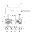
- FIG. 2 is a diagram illustrating a first example of the configuration of the optical communication device 10 according to the embodiment of the present invention.
- illustration of the controller 11 provided in the optical communication device 10 is omitted.
- the first to fifth examples of the configuration of the optical communication apparatus 10 described below are different with respect to the internal configuration of the transponder aggregation optical switch 13 and the presence / absence of the third optical switch 18, and the route selection optical switch 12, noise
- the configurations of the adding unit 14 and the transponder bank 15 are common.
- the optical communication apparatus 10 of the present example has, as an internal configuration of the transponder aggregation optical switch 13, a first light that outputs an optical signal input from either the external or the noise adding unit 14 to at least one of the plurality of optical transponders.
- the switch 16 includes a second optical switch 17 that directly or indirectly outputs an optical signal input from at least one of the plurality of optical transponders to either the outside or the noise adding unit 14. More specifically, the first optical switch 16 outputs an optical signal input from any one of the outside and the noise adding unit 14 to any one of the plurality of optical transponders and the third optical switch 18, and the second optical switch 17. Outputs an optical signal input from any of the plurality of optical transponders to either the external or the third optical switch 18.
- the optical signal input from the outside is an optical signal input from the externally connected optical fiber F (see FIG. 1) via the route selection optical switch 12.
- directly or indirectly outputting an optical signal to the outside means outputting the optical signal to the optical fiber F connected to the outside via the route selection optical switch 12.
- the first optical switch 16 includes a plurality of first optical splitters 16a that branch an optical signal input from either the outside or the noise adding unit 14, and light input from the plurality of first optical splitters 16a.
- the plurality of first optical splitters 16a are indicated by circles in FIG. 2, and receive optical signals input from the outside, that is, optical signals input from the optical fiber F connected externally via the path selection optical switch 12. , Branch and output to a plurality of fifth optical switches 16b.
- the plurality of fifth optical switches 16b are shown as squares in the figure, and output the input optical signal to the corresponding optical transponder or the third optical switch 18.
- the plurality of fifth optical switches 16b may or may not output an optical signal to the optical transponder or the third optical switch 18 based on a control signal received from the controller 11.
- the optical signal input from the externally connected optical fiber F is sent to the first optical transponder 15a, the second optical transponder 15b, the third optical transponder 15c, the fourth optical transponder 15d, and the third optical switch 18. Selectively output.
- the second optical switch 17 is input from a plurality of sixth optical switches 17b that output optical signals input from a plurality of optical transponders to a selected output destination, and a plurality of sixth optical switches 17b. And a plurality of second optical splitters 17 a that output the optical signal to any one of the outside, the noise adding unit 14, and the third optical switch 18.
- the plurality of sixth optical switches 17b are shown as squares in the figure, and receive optical signals input from any of the first optical transponder 15a, the second optical transponder 15b, the third optical transponder 15c, and the fourth optical transponder 15d. Based on the control signal received from the controller 11, the signal is output to any one of the plurality of second optical splitters 17a, or is not output.
- the plurality of second optical splitters 17 a are illustrated by circles in FIG. 5, and the optical signals input from the plurality of sixth optical switches 17 b Output to either.
- the optical signal output from the first optical transponder 15a is input to one of the plurality of sixth optical switches 17b (the optical switch illustrated second from the left in the drawing), and the plurality of second optical splitters. It is transmitted to one of 17a (the leftmost optical splitter shown in the figure) and input to the third optical switch 18 from the optical splitter.
- the third optical switch 18 outputs the input optical signal to the noise adding unit 14.
- the noise adding unit 14 adds noise that lowers the signal quality to the input optical signal, and selects one of the plurality of first optical splitters 16a (the optical splitter illustrated on the right in the drawing). ).
- the optical signal to which the noise is added is transmitted from the optical splitter to the plurality of fifth optical switches 16b, and one of the plurality of fifth optical switches 16b (the light illustrated second from the left in the figure). Switch) to the second optical transponder 15b.
- the controller 11 of the optical communication apparatus 10 compares the optical signal transmitted by the first optical transponder 15a, the noise added by the noise adding unit 14, and the optical signal received by the second optical transponder 15b, and relates to the communication quality. It measures how much margin is secured with respect to a predetermined standard, and measures the communication quality between the first optical transponder 15a and the second optical transponder 15b.
- the communication quality is measured between the first optical transponder 15a and the second optical transponder 15b has been described.
- the communication quality can be measured between arbitrary optical transponders. it can.
- communication quality can be measured simultaneously for a plurality of optical transponder pairs, and an optical signal transmitted from one optical transponder can be received by a plurality of optical transponders to achieve one-to-many communication quality. It can also be measured.
- the noise adding unit 14 intentionally adds noise to an optical signal transmitted between a plurality of optical transponders, thereby providing a device provided by a different vendor or different.
- an optical communication network including a generation device When an optical communication network including a generation device is constructed, communication quality can be measured on demand. Therefore, it is possible to specify a combination of devices having a communication quality of a certain level or more, and to introduce devices having various performances, and thus it is possible to suppress an increase in equipment cost.
- the controller 11 controls the plurality of optical transponders, the noise adding unit 14, the first optical switch 16, and the second optical switch 17.
- the optical communication apparatus 10 includes the controller 11 and can autonomously measure communication quality between a plurality of optical transponders.
- the optical signal output from the optical transponder included in the other optical communication device 10 is transmitted through the optical fiber F (see FIG. 1), and the plurality of first optical splitters 16 a of the first optical switch 16 are transmitted by the path selection optical switch 12. Is input to any of the above.
- the first optical splitter 16a Upon receiving the input, the first optical splitter 16a outputs the optical signal to the plurality of fifth optical switches 16b.
- One of the plurality of fifth optical switches 16b (the optical splitter shown on the right in FIG. 2) outputs the input optical signal to the third optical switch 18, and the third optical switch 18 receives the input.
- the optical signal thus output is output to the noise adding unit 14.
- the noise adding unit 14 adds noise that lowers the signal quality to the input optical signal, and selects one of the plurality of first optical splitters 16a (the optical splitter illustrated on the right in the drawing). ).
- the optical signal to which the noise is added is transmitted from the optical splitter to the plurality of fifth optical switches 16b, and one of the plurality of fifth optical switches 16b (the optical switch illustrated on the left in the drawing).
- the controller 11 of the optical communication device 10 compares the optical signal transmitted by the optical transponder included in the other optical communication device 10, the noise added by the noise adding unit 14, and the optical signal received by the first optical transponder 15a.
- optical transponder included in the other optical communication device 10 and the first optical transponder 15a is measured.
- communication quality can be measured between any optical transponders.
- communication quality can be measured simultaneously for a plurality of optical transponder pairs, and an optical signal transmitted from one optical transponder can be received by a plurality of optical transponders to achieve one-to-many communication quality. It can also be measured.
- the optical communication apparatus 10 includes the third optical switch 18 to which an optical signal is input from the first optical switch 16, thereby adding noise to the optical signal input from the outside, Can be transmitted to the transponder. Therefore, it is possible to easily measure the communication quality between the optical transponders included in each of the two or more optical communication devices 10.
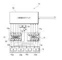
- FIG. 3 is a diagram illustrating a second example of the configuration of the optical communication device 10 according to the embodiment of the present invention.
- the optical communication apparatus 10 of this example is different from the first example in that the third optical switch 18 is not provided and the internal configuration of the transponder aggregation optical switch 13 is different.
- the first optical switch 16 of this example outputs an optical signal input from either the external or the noise adding unit 14 to any one of the plurality of optical transponders and the second optical switch 17, and the second optical switch 17
- the optical signal input from any of the plurality of optical transponders and the first optical switch 16 is output to either the external or the noise adding unit 14.
- the first optical switch 16 includes a plurality of first optical splitters 16a that branch an optical signal input from either the outside or the noise adding unit 14, and light input from the plurality of first optical splitters 16a.
- the plurality of first optical splitters 16a are indicated by circles in the figure, and receive optical signals input from the outside, that is, optical signals input from the optical fiber F connected externally via the path selection optical switch 12. , Branch and output to a plurality of fifth optical switches 16b.
- the plurality of fifth optical switches 16 b are illustrated as squares in the figure, and output the input optical signal to the corresponding optical transponder or the second optical switch 17.
- the plurality of fifth optical switches 16 b may or may not output the optical signal to the optical transponder or the second optical switch 17 based on the control signal received from the controller 11.
- the optical signal input from the externally connected optical fiber F is sent to the first optical transponder 15a, the second optical transponder 15b, the third optical transponder 15c, the fourth optical transponder 15d, and the second optical switch 17. Selectively output.
- the second optical switch 17 includes a plurality of sixth optical switches 17b and eighth that output optical signals input from any of the plurality of optical transponders and the first optical switch 16 to the selected output destination. It includes an optical switch 17c and a plurality of second optical splitters 17a that output optical signals input from the plurality of sixth optical switches 17b and the eighth optical switch 17c to either the outside or the noise adding unit 14.
- a plurality of sixth optical switches 17b and eighth optical switches 17c are shown as squares in the figure, and the first optical transponder 15a, the second optical transponder 15b, the third optical transponder 15c, the fourth optical transponder 15d, and the first light.
- the optical signal input from any one of the switches 16 is output to any one of the plurality of second optical splitters 17a, or is not output.
- the plurality of second optical splitters 17a are indicated by circles in the figure, and the optical signals input from the plurality of sixth optical switches 17b and the eighth optical switch 17c are sent to the route selection optical switch 12 and the noise adding unit 14. Output to either.
- the optical signal output from the first optical transponder 15a is input to one of the plurality of sixth optical switches 17b (the optical switch illustrated second from the left in the drawing), and the plurality of second optical splitters. It is transmitted to one of 17a (the optical splitter shown on the left in the figure), and is input to the noise adding unit 14 from the optical splitter.
- the noise adding unit 14 adds noise that lowers the signal quality to the input optical signal, and selects one of the plurality of first optical splitters 16a (the optical splitter illustrated on the right in the drawing). ).
- the optical signal to which the noise is added is transmitted from the optical splitter to the plurality of fifth optical switches 16b, and one of the plurality of fifth optical switches 16b (the light illustrated second from the left in the figure). Switch) to the second optical transponder 15b.
- the controller 11 of the optical communication apparatus 10 compares the optical signal transmitted by the first optical transponder 15a, the noise added by the noise adding unit 14, and the optical signal received by the second optical transponder 15b, and relates to the communication quality. It measures how much margin is secured with respect to a predetermined standard, and measures the communication quality between the first optical transponder 15a and the second optical transponder 15b.
- the optical signal output from the optical transponder included in the other optical communication device 10 is transmitted through the optical fiber F (see FIG. 1), and the plurality of first optical splitters 16 a of the first optical switch 16 are transmitted by the path selection optical switch 12. Is input to any of the above.
- the first optical splitter 16a Upon receiving the input, the first optical splitter 16a outputs the optical signal to the plurality of fifth optical switches 16b.
- One of the plurality of fifth optical switches 16b (the optical splitter shown on the right in FIG.
- the eighth optical switch 17c outputs the input optical signal to one of the plurality of second optical splitters 17a (the optical splitter illustrated on the left in the drawing).
- the optical signal is input to the noise adding unit 14 from the optical splitter, and the noise adding unit 14 adds noise that degrades the signal quality to the input optical signal, and the plurality of first optical splitters 16a. It outputs to one of them (the optical splitter shown on the right in the figure).
- the optical signal to which the noise is added is transmitted from the optical splitter to the plurality of fifth optical switches 16b, and one of the plurality of fifth optical switches 16b (the optical switch illustrated on the left in the drawing). To the first optical transponder 15a.
- the controller 11 of the optical communication device 10 compares the optical signal transmitted by the optical transponder included in the other optical communication device 10, the noise added by the noise adding unit 14, and the optical signal received by the first optical transponder 15a. Then, it is measured how much margin is ensured with respect to a predetermined standard related to communication quality, and communication quality between the optical transponder included in the other optical communication device 10 and the first optical transponder 15a is measured. Do. Here, the case where the communication quality is measured between the optical transponder included in the other optical communication device 10 and the first optical transponder 15a has been described. Similarly, the optical transponder included in the other optical communication device 10 Communication quality can be measured between any optical transponders. In addition, communication quality can be measured simultaneously for a plurality of optical transponder pairs, and an optical signal transmitted from one optical transponder can be received by a plurality of optical transponders to achieve one-to-many communication quality. It can also be measured.
- the first optical switch 16 outputs an optical signal to the second optical switch 17, so that an optical switch independent of the first optical switch 16 and the second optical switch 17 is provided.
- the noise adding unit can add noise to the optical signal and transmit it to the optical transponder. Therefore, it is possible to easily measure the communication quality between the optical transponders included in each of the two or more optical communication devices, and to suppress an increase in the number of parts.
- FIG. 4 is a diagram illustrating a third example of the configuration of the optical communication device 10 according to the embodiment of the present invention.
- the optical communication device 10 of this example is different from the case of the first example in that the internal configuration of the transponder aggregation optical switch 13 is different.
- the first optical switch 16 of this example includes a fourth optical switch 16c that outputs the optical signal input from the noise adding unit 14 to a selected output destination.
- the first optical switch 16 includes a plurality of first optical splitters 16a for branching an optical signal input from either the outside or the noise adding unit 14, and an optical signal input from the noise adding unit 14.
- the fourth optical switch 16c that outputs to the selected output destination and the optical signals input from any of the plurality of first optical splitters 16a and the fourth optical switch 16c are sent to the plurality of optical transponders and the second optical switch 17 A plurality of fifth optical switches 16b that output to any one of them.
- the plurality of first optical splitters 16a are indicated by circles in the figure, and receive optical signals input from the outside, that is, optical signals input from the optical fiber F connected externally via the path selection optical switch 12. , Branch and output to a plurality of fifth optical switches 16b.
- the fourth optical switch 16c is shown as a square in the drawing.
- the plurality of fifth optical switches 16 b are illustrated as squares in the figure, and output the input optical signal to the corresponding optical transponder or the second optical switch 17.
- the plurality of fifth optical switches 16b may or may not output an optical signal to the optical transponder or the third optical switch 18 based on a control signal received from the controller 11.
- the optical signal input from the externally connected optical fiber F (see FIG. 1) is converted into the first optical transponder 15a, the second optical transponder 15b, the third optical transponder 15c, the fourth optical transponder 15d, and the first optical transponder 15d.
- the signal is selectively output to the three optical switch 18.
- the second optical switch 17 includes a plurality of sixth optical switches 17b that output optical signals input from any of the plurality of optical transponders and the first optical switch 16 to a selected output destination, and a plurality of optical signals.
- the plurality of sixth optical switches 17b are illustrated by squares in FIG. 4, and the optical signals input from any of the first optical transponder 15a, the second optical transponder 15b, the third optical transponder 15c, and the fourth optical transponder 15d are displayed. Based on the control signal received from the controller 11, the signal is output to any one of the plurality of second optical splitters 17a, or is not output.
- the plurality of second optical splitters 17a are indicated by circles in the drawing, and the optical signals input from the plurality of sixth optical switches 17b and the eighth optical switch 17c are routed to the path selection optical switch 12 and the third optical switch 18. Output to either of these
- the optical signal output from the first optical transponder 15a is input to one of the plurality of sixth optical switches 17b (the optical switch illustrated second from the left in the drawing), and the plurality of second optical splitters. It is transmitted to one of 17a (the leftmost optical splitter shown in the figure) and input to the third optical switch 18 from the optical splitter.
- the third optical switch 18 outputs the input optical signal to the noise adding unit 14.
- the noise adding unit 14 adds noise that degrades signal quality to the input optical signal and outputs the added signal to the fourth optical switch 16c.
- the optical signal to which noise is added is transmitted from the fourth optical switch 16c to one of the plurality of fifth optical switches 16b (the optical switch shown second from the left in the drawing), and the fifth optical switch 16c.
- the light is output from the optical switch 16b to the second optical transponder 15b.
- the controller 11 of the optical communication apparatus 10 compares the optical signal transmitted by the first optical transponder 15a, the noise added by the noise adding unit 14, and the optical signal received by the second optical transponder 15b, and relates to the communication quality. It measures how much margin is secured with respect to a predetermined standard, and measures the communication quality between the first optical transponder 15a and the second optical transponder 15b.
- the communication quality can be measured between arbitrary optical transponders. it can.
- communication quality can be measured simultaneously for a plurality of optical transponder pairs, and an optical signal transmitted from one optical transponder can be received by a plurality of optical transponders to achieve one-to-many communication quality. It can also be measured.
- the optical signal output from the optical transponder included in the other optical communication device 10 is transmitted through the optical fiber F (see FIG. 1), and the plurality of first optical splitters 16 a of the first optical switch 16 are transmitted by the path selection optical switch 12. Is input to any of the above.
- the first optical splitter 16a Upon receiving the input, the first optical splitter 16a outputs the optical signal to the plurality of fifth optical switches 16b.
- One of the plurality of fifth optical switches 16b (the optical splitter illustrated on the right in FIG. 4) outputs the input optical signal to the third optical switch 18, and the third optical switch 18 receives the input.
- the optical signal thus output is output to the noise adding unit 14.
- the noise adding unit 14 adds noise that degrades signal quality to the input optical signal and outputs the added signal to the fourth optical switch 16c.
- the optical signal to which noise is added is transmitted from the fourth optical switch 16c to one of the plurality of fifth optical switches 16b (the optical switch shown on the left in the drawing), and the fifth optical switch 16b is output to the first optical transponder 15a.
- the controller 11 of the optical communication device 10 compares the optical signal transmitted by the optical transponder included in the other optical communication device 10, the noise added by the noise adding unit 14, and the optical signal received by the first optical transponder 15a.
- optical transponder included in the other optical communication device 10 and the first optical transponder 15a is measured.
- communication quality can be measured between any optical transponders.
- communication quality can be measured simultaneously for a plurality of optical transponder pairs, and an optical signal transmitted from one optical transponder can be received by a plurality of optical transponders to achieve one-to-many communication quality. It can also be measured.
- the optical signal input from the noise adding unit 14 to the first optical switch 16 is distributed from the fourth optical switch 16c to the plurality of fifth optical switches 16b, thereby providing an optical signal.
- the number of times an optical signal passes through the optical splitter can be reduced as compared with the case where the optical signal is distributed from the splitter to the plurality of fifth optical switches 16b. Therefore, a margin for adding noise that can be used for measuring the communication quality between the optical transponders included in each of the two or more optical communication devices 10 is increased, and the measurement of the communication quality can be performed more flexibly.
- FIG. 5 is a diagram illustrating a fourth example of the configuration of the optical communication device 10 according to the embodiment of the present invention.
- the optical communication apparatus 10 of this example is different from the first example in that the third optical switch 18 is not provided and the internal configuration of the transponder aggregation optical switch 13 is different.
- the first optical switch 16 of this example outputs an optical signal input from either the external or the noise adding unit 14 to any one of the plurality of optical transponders and the second optical switch 17, and the second optical switch 17
- the optical signal input from any of the plurality of optical transponders and the first optical switch 16 is output to either the external or the noise adding unit 14.
- the first optical switch 16 of this example includes a fourth optical switch 16c that outputs the optical signal input from the noise adding unit 14 to a selected output destination.
- the first optical switch 16 outputs a plurality of first optical splitters 16a for branching an optical signal input from the outside and an optical signal input from the noise adding unit 14 to a selected output destination.
- the fourth optical switch 16c and a plurality of fifth optical switches that output optical signals input from the plurality of first optical splitters 16a and the fourth optical switch 16c to any one of the plurality of optical transponders and the second optical switch 17. 16b.
- the plurality of first optical splitters 16a are indicated by circles in the figure, and receive optical signals input from the outside, that is, optical signals input from the optical fiber F connected externally via the path selection optical switch 12. , Branch and output to a plurality of fifth optical switches 16b.
- the fourth optical switch 16c is shown as a square in the drawing.
- the plurality of fifth optical switches 16 b are illustrated as squares in the figure, and output the input optical signal to the corresponding optical transponder or the second optical switch 17.
- the plurality of fifth optical switches 16 b may or may not output the optical signal to the optical transponder or the second optical switch 17 based on the control signal received from the controller 11.
- the optical signal input from the externally connected optical fiber F is sent to the first optical transponder 15a, the second optical transponder 15b, the third optical transponder 15c, the fourth optical transponder 15d, and the second optical switch 17. Selectively output.
- the second optical switch 17 includes a plurality of sixth optical switches 17b and eighth that output optical signals input from any of the plurality of optical transponders and the first optical switch 16 to the selected output destination. It includes an optical switch 17c and a plurality of second optical splitters 17a that output optical signals input from the plurality of sixth optical switches 17b and the eighth optical switch 17c to either the outside or the noise adding unit 14.
- a plurality of sixth optical switches 17b and eighth optical switches 17c are shown as squares in the figure, and the first optical transponder 15a, the second optical transponder 15b, the third optical transponder 15c, the fourth optical transponder 15d, and the first light.
- the optical signal input from any one of the switches 16 is output to any one of the plurality of second optical splitters 17a, or is not output.
- the plurality of second optical splitters 17a are indicated by circles in the figure, and the optical signals input from the plurality of sixth optical switches 17b and the eighth optical switch 17c are sent to the route selection optical switch 12 and the noise adding unit 14. Output to either.
- the optical signal output from the first optical transponder 15a is input to one of the plurality of sixth optical switches 17b (the optical switch illustrated second from the left in FIG. 5), and the plurality of second optical splitters. It is transmitted to one of 17a (the optical splitter shown on the left in the figure), and is input to the noise adding unit 14 from the optical splitter.
- the noise adding unit 14 adds noise that degrades signal quality to the input optical signal and outputs the added signal to the fourth optical switch 16c.
- the optical signal to which noise is added is transmitted from the fourth optical switch 16c to one of the plurality of fifth optical switches 16b (the optical switch shown second from the left in the figure), and the fifth optical switch
- the signal is output from the switch 16b to the second optical transponder 15b.
- the controller 11 of the optical communication apparatus 10 compares the optical signal transmitted by the first optical transponder 15a, the noise added by the noise adding unit 14, and the optical signal received by the second optical transponder 15b, and relates to the communication quality. It measures how much margin is secured with respect to a predetermined standard, and measures the communication quality between the first optical transponder 15a and the second optical transponder 15b.
- the optical signal output from the optical transponder included in the other optical communication device 10 is transmitted through the optical fiber F (see FIG. 1), and the plurality of first optical splitters 16 a of the first optical switch 16 are transmitted by the path selection optical switch 12. Is input to any of the above.
- the first optical splitter 16a Upon receiving the input, the first optical splitter 16a outputs the optical signal to the plurality of fifth optical switches 16b.
- One of the plurality of fifth optical switches 16b (the optical splitter illustrated on the right in FIG.
- the eighth optical switch 17c outputs the input optical signal to one of the plurality of second optical splitters 17a (the optical splitter illustrated on the left in the drawing).
- the optical signal is input to the noise adding unit 14 from the optical splitter, and the noise adding unit 14 adds noise that degrades the signal quality to the input optical signal and outputs the noise to the fourth optical switch 16c.
- the optical signal to which noise is added is transmitted from the fourth optical switch 16c to one of the plurality of fifth optical switches 16b (the optical switch shown on the left in the drawing), and the fifth optical switch 16b. To the first optical transponder 15a.
- the controller 11 of the optical communication device 10 compares the optical signal transmitted by the optical transponder included in the other optical communication device 10, the noise added by the noise adding unit 14, and the optical signal received by the first optical transponder 15a. Then, it is measured how much margin is ensured with respect to a predetermined standard related to communication quality, and communication quality between the optical transponder included in the other optical communication device 10 and the first optical transponder 15a is measured. Do. Here, the case where the communication quality is measured between the optical transponder included in the other optical communication device 10 and the first optical transponder 15a has been described. Similarly, the optical transponder included in the other optical communication device 10 Communication quality can be measured between any optical transponders. In addition, communication quality can be measured simultaneously for a plurality of optical transponder pairs, and an optical signal transmitted from one optical transponder can be received by a plurality of optical transponders to achieve one-to-many communication quality. It can also be measured.
- the first optical switch 16 outputs an optical signal to the second optical switch 17, so that an optical switch independent of the first optical switch 16 and the second optical switch 17 is provided.
- the noise adding unit 14 can add noise to the optical signal and transmit it to the optical transponder without increasing the number of the optical transponders.
- the optical signal input from the noise adding unit 14 to the first optical switch 16 is distributed from the fourth optical switch 16c to the plurality of fifth optical switches 16b, so that the optical signal is distributed from the optical splitter to the plurality of fifth optical switches 16b.
- the number of times the optical signal passes through the optical splitter can be reduced, and the noise addition allowable amount by the noise addition unit 14 is increased. For this reason, a margin for adding noise that can be used for measuring the communication quality between the optical transponders included in each of the two or more optical communication apparatuses is increased, so that the communication quality can be measured more flexibly.
- FIG. 6 is a diagram illustrating a fifth example of the configuration of the optical communication device 10 according to the embodiment of the present invention.
- the optical communication apparatus 10 of this example is different from the first example in that the third optical switch 18 is not provided and the internal configuration of the transponder aggregation optical switch 13 is different.
- the first optical switch 16 of this example outputs an optical signal input from either the external or the noise adding unit 14 to any one of the plurality of optical transponders and the second optical switch 17, and the second optical switch 17
- the optical signal input from any of the plurality of optical transponders and the first optical switch 16 is output to either the external or the noise adding unit 14.
- the first optical switch 16 of this example includes a fourth optical switch 16c that outputs the optical signal input from the noise adding unit 14 to a selected output destination.
- the second optical switch 17 of the present example includes a seventh optical switch 17 d that outputs the optical signals input from the plurality of sixth optical switches 17 b to the noise adding unit 14.
- the first optical switch 16 outputs a plurality of first optical splitters 16a for branching an optical signal input from the outside and an optical signal input from the noise adding unit 14 to a selected output destination.
- the fourth optical switch 16c and a plurality of fifth optical switches that output optical signals input from the plurality of first optical splitters 16a and the fourth optical switch 16c to any one of the plurality of optical transponders and the second optical switch 17. 16b.
- the plurality of first optical splitters 16a are indicated by circles in the drawing, and are input from an optical signal input from the outside, that is, an optical fiber F (see FIG. 1) externally connected via the path selection optical switch 12. The optical signal thus split is branched and output to a plurality of fifth optical switches 16b.
- the fourth optical switch 16c is illustrated by a square in FIG.
- the plurality of fifth optical switches 16 b are illustrated as squares in the figure, and output the input optical signal to the corresponding optical transponder or the second optical switch 17.
- the plurality of fifth optical switches 16 b may or may not output the optical signal to the optical transponder or the second optical switch 17 based on the control signal received from the controller 11.
- the optical signal input from the externally connected optical fiber F is sent to the first optical transponder 15a, the second optical transponder 15b, the third optical transponder 15c, the fourth optical transponder 15d, and the second optical switch 17. Selectively output.
- the second optical switch 17 includes a plurality of sixth optical switches 17b and eighth that output optical signals input from any of the plurality of optical transponders and the first optical switch 16 to the selected output destination.
- a seventh optical switch 17d that outputs the optical signal input from the switch 17c to the noise adding unit 14.
- a plurality of sixth optical switches 17b and eighth optical switches 17c are shown as squares in the figure, and the first optical transponder 15a, the second optical transponder 15b, the third optical transponder 15c, the fourth optical transponder 15d, and the first light.
- the optical signal input from any one of the switches 16 is output to one of the plurality of second optical splitters 17a and the seventh optical switch 17d, or is not output.
- the plurality of second optical splitters 17 a are illustrated by circles in the drawing, and output optical signals input from the plurality of sixth optical switches 17 b and the eighth optical switch 17 c to the route selection optical switch 12.
- the seventh optical switch 17d is shown as a square in the drawing, and outputs the optical signals input from the plurality of sixth optical switches 17b and the eighth optical switch 17c to the noise adding unit 14.
- the optical signal output from the first optical transponder 15a is input to one of the plurality of sixth optical switches 17b (the optical switch illustrated second from the left in the figure), and is input to the seventh optical switch 17d. Is transmitted to the noise adding unit 14 from the seventh optical switch 17d.
- the noise adding unit 14 adds noise that degrades signal quality to the input optical signal and outputs the added signal to the fourth optical switch 16c.
- the optical signal to which noise is added is transmitted from the fourth optical switch 16c to one of the plurality of fifth optical switches 16b (the optical switch shown second from the left in the figure), and the fifth optical switch
- the signal is output from the switch 16b to the second optical transponder 15b.
- the controller 11 of the optical communication apparatus 10 compares the optical signal transmitted by the first optical transponder 15a, the noise added by the noise adding unit 14, and the optical signal received by the second optical transponder 15b, and relates to the communication quality. It measures how much margin is secured with respect to a predetermined standard, and measures the communication quality between the first optical transponder 15a and the second optical transponder 15b.
- the optical signal output from the optical transponder included in the other optical communication device 10 is transmitted through the optical fiber F (see FIG. 1), and the plurality of first optical splitters 16 a of the first optical switch 16 are transmitted by the path selection optical switch 12. Is input to any of the above.
- the first optical splitter 16a Upon receiving the input, the first optical splitter 16a outputs the optical signal to the plurality of fifth optical switches 16b.
- One of the plurality of fifth optical switches 16b (the optical splitter illustrated on the right in FIG.
- the eighth optical switch 17c outputs the input optical signal to the seventh optical switch 17d.
- the optical signal is input from the seventh optical switch 17d to the noise adding unit 14, and the noise adding unit 14 adds noise that degrades the signal quality to the input optical signal, and supplies it to the fourth optical switch 16c. Output.
- the optical signal to which noise is added is transmitted from the fourth optical switch 16c to one of the plurality of fifth optical switches 16b (the optical switch shown on the left in the drawing), and the fifth optical switch 16b. To the first optical transponder 15a.
- the controller 11 of the optical communication device 10 compares the optical signal transmitted by the optical transponder included in the other optical communication device 10, the noise added by the noise adding unit 14, and the optical signal received by the first optical transponder 15a. Then, it is measured how much margin is ensured with respect to a predetermined standard related to communication quality, and communication quality between the optical transponder included in the other optical communication device 10 and the first optical transponder 15a is measured. Do. Here, the case where the communication quality is measured between the optical transponder included in the other optical communication device 10 and the first optical transponder 15a has been described. Similarly, the optical transponder included in the other optical communication device 10 Communication quality can be measured between any optical transponders. In addition, communication quality can be measured simultaneously for a plurality of optical transponder pairs, and an optical signal transmitted from one optical transponder can be received by a plurality of optical transponders to achieve one-to-many communication quality. It can also be measured.
- the second optical splitter 17a is transmitted by transmitting the optical signal input from the optical transponder to the second optical switch 17 from the seventh optical switch 17d to the noise adding unit 14.
- the number of times that the optical signal passes through the optical splitter can be reduced, and the allowable amount of noise addition by the noise adding unit 14 is increased as compared with the case of transmitting to the noise adding unit 14. Therefore, a margin for adding noise that can be used for measuring the communication quality between the optical transponders included in each of the two or more optical communication devices 10 is increased, and the measurement of the communication quality can be performed more flexibly.
- the port of the transponder aggregation optical switch 13 connected to the route selection optical switch 12 since the port of the transponder aggregation optical switch 13 connected to the route selection optical switch 12 includes an optical splitter, it passes through the noise adding unit 14.
- C / D / C Colorless, “Directionless,” and “Contentionless” connection functions are not impaired for optical signals that are not transmitted.
- FIG. 7 is a diagram showing functional blocks of the management apparatus 100 according to the embodiment of the present invention.
- the management apparatus 100 includes a communication unit 101, a storage unit 102, a calculation unit 103, an estimation unit 104, and an extraction unit 105.
- the communication unit 101 is configured by a communication interface, and transmits setting information of a path for transmitting an optical signal to the controller 11 of the optical communication apparatus 10 or receives information on a communication quality measurement result from the controller 11. .
- the storage unit 102 stores a combination of optical transponder types for which communication quality has already been measured among a plurality of optical transponders, together with a communication quality measurement result related to the combination.
- the calculation unit 103 is a path for transmitting an optical signal from one of the two optical communication devices 10 (hereinafter referred to as a first optical communication device) to the other (hereinafter referred to as a second optical communication device). Calculate transmission characteristics.
- the estimation unit 104 stores the storage unit 102 when the combination of the optical transponder of the first optical communication device and the optical transponder of the second optical communication device is a combination of types of optical transponders for which communication quality has already been measured.
- the communication quality is estimated based on the measurement result of the communication quality stored in the communication unit 103 and the transmission characteristic calculated by the calculation unit 103.
- the extraction unit 105 extracts a combination of optical transponder types for which communication quality is not measured from among a plurality of optical transponders.
- the calculation unit 103, the estimation unit 104, and the extraction unit 105 are functional units realized by a processor included in the management device 100.
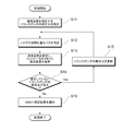
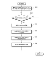
- FIG. 8 is a flowchart of the first process executed by the optical communication system 1 according to the embodiment of the present invention.
- the first process is a process executed by one optical communication apparatus 10 and the management apparatus 100 included in the optical communication system 1 and is a process for measuring communication quality between a plurality of optical transponders included in the optical communication apparatus 10. is there.
- the optical communication device 10 transmits an optical signal so as to pass through the noise adding unit 14 from one of the two optical transponders to the other, and notifies the management device 100 of the measurement result of measuring the communication quality. To do.
- the optical communication device 10 sets a combination of optical transponders for measuring communication quality among a plurality of optical transponders provided in the optical communication device 10 (S11).
- the combination of optical transponders for measuring communication quality may be a combination of selecting two optical transponders from among a plurality of optical transponders, and is possible when the optical communication apparatus 10 includes N optical transponders. There are N (N-1) / 2 combinations at maximum.
- the setting of the combination of optical transponders for measuring communication quality may be performed by the management apparatus 100.
- the optical communication device 10 sets the transmission path of the optical signal so that the transmitted optical signal passes through the noise adding unit 14 at least once for the combination of optical transponders for measuring the communication quality (S12).
- the transmission path is set by setting control signals for the first optical switch 16 and the second optical switch 17 included in the transponder aggregation optical switch 13.
- the setting of the optical signal transmission path may be performed by the management apparatus 100.
- the optical communication device 10 transmits / receives an optical signal with respect to the set optical transponder pair through the transmission path of the set optical signal, measures the communication quality of the optical transponder pair, and stores it in the memory of the controller 11 ( S13). Thereafter, it is determined whether or not a combination of optical transponders for measuring communication quality remains (S14). When the combination of the optical transponders for measuring the communication quality remains (S14: Yes), the setting of the optical transponder combination is updated (S15), the transmission path of the optical signal is newly set (S12), and the communication is performed. The quality is measured and stored in the memory of the controller 11 (S13).
- the management device 100 (NMS) is collectively notified of the communication quality measurement results (S16).
- the management apparatus 100 stores the communication quality measurement result in the storage unit 102 in association with the combination of the optical transponders that are the measurement targets. Thus, the first process ends.
- measurement results obtained by measuring communication quality between a plurality of optical transponders included in the optical communication device 10 can be managed together by the management device 100, and other optical communication devices can be managed. 10, when confirmation of communication quality regarding the same optical transponder is requested, the measurement result can be diverted to make the confirmation of communication quality more efficient.
- communication quality can be increased on demand without imposing a large processing load and communication load on the management device 100. Can be measured.
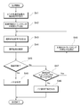
- FIG. 9 is a flowchart of the second process executed by the optical communication system 1 according to the embodiment of the present invention.
- the second process is a process executed by the two optical communication devices 10 and the management device 100 included in the optical communication system 1, and the communication quality between the plurality of optical transponders respectively included in the two optical communication devices 10 is determined. It is a process to measure.
- one of the two optical communication devices 10 for measuring communication quality is referred to as a first optical communication device, and the other is referred to as a second optical communication device.
- the first optical communication device transmits an optical signal from one of the plurality of optical transponders to the second optical communication device, and the second optical communication device transmits the optical signal through the noise adding unit 14.
- the first optical communication device and the second optical communication device notify the management device 100 of the measurement results obtained by measuring the communication quality.
- the management device 100 sets a combination of the optical communication devices 10 included in the communication network of the optical communication system 1 (S21).
- the combination of the optical communication devices 10 for measuring the communication quality may be a combination of selecting two optical communication devices 10 from a plurality of optical communication devices 10 included in the communication network, and there are N communication networks.
- the maximum possible combinations are N (N ⁇ 1) / 2.
- the first optical communication device and the second optical communication device are a combination of optical transponders that measure communication quality among a plurality of optical transponders that are respectively included in the first optical communication device and second optical communication device that measure communication quality.
- the management device 100 controls the route selection optical switch 12 of the other optical communication device 10 interposed between the first optical communication device and the second optical communication device, and the first optical communication device to the second optical communication device.
- the transmission path of the optical signal is set so that the optical signal is transmitted to the network.
- the first optical communication device and the second optical communication device set the transmission path of the optical signal so that the transmitted optical signal passes through the noise adding unit 14 at least once for the pair of optical transponders that measure the communication quality. (S23).
- the transmission path may be set so as to pass through the noise adding unit 14 in the second optical communication apparatus on the receiving side.
- the first optical communication device and the second optical communication device transmit and receive an optical signal on the set optical signal transmission path with respect to the set optical transponder pair, measure the communication quality of the optical transponder pair,
- the data is stored in the memory of each controller 11 (S24). Thereafter, it is determined whether or not a combination of optical transponders for measuring communication quality remains (S25). When the combination of the optical transponders for measuring the communication quality remains (S25: Yes), the setting of the optical transponder combination is updated (S26), the transmission path of the optical signal is newly set (S23), and the communication is performed.
- the quality is measured and stored in the memory of the controller 11 (S24).
- the measurement of communication quality may be performed in both directions or in one direction.
- the update timing may be notified from the management device 100 to the first optical communication device and the second optical communication device, or the first optical communication device and the second optical device may be notified in advance.
- the communication device may determine the relationship between the master device and the slave device and notify the slave device of the update timing from the master device.
- the first optical communication device and the second optical communication device summarize the communication quality measurement results in the management device 100 (NMS). (S27).
- the management apparatus 100 stores the communication quality measurement result in the storage unit 102 in association with the combination of the optical transponders that are the measurement targets. Thus, the second process ends.
- the management device 100 can collectively manage the measurement results obtained by measuring the communication quality between a plurality of optical transponders included in each pair of the optical communication devices 10.
- the measurement result can be diverted to improve the efficiency of confirmation of communication quality.
- information such as the amount of noise added from the transmission-side optical communication apparatus 10 by adding noise in the reception-side optical communication apparatus 10. Is not required to be transmitted to the optical communication device 10 on the receiving side, so that the communication quality measurement process can be simplified.
- FIG. 10 is a flowchart of the third process executed by the optical communication system 1 according to the embodiment of the present invention.
- the third process is a process executed by the two optical communication devices 10 and the management device 100 included in the optical communication system 1, and a plurality of optical transponders respectively provided in the two optical communication devices 10 are measured as In this process, the pair of optical transponders to be updated is autonomously updated by the two optical communication devices 10 and the communication quality is measured.
- one of the two optical communication devices 10 for measuring communication quality is referred to as a first optical communication device, and the other is referred to as a second optical communication device.
- the first optical communication apparatus and the second optical communication apparatus update a combination of a plurality of optical transponders that measure communication quality at a predetermined cycle, respectively measure the communication quality,
- the second optical communication device notifies the management device 100 of the measurement results obtained by measuring the communication quality.
- the management device 100 sets an update cycle for measuring communication quality (S31).
- the update cycle is a cycle for updating a pair of optical transponders for measuring communication quality, and can be an arbitrary time cycle. Note that the update period may be set by the optical communication device 10.
- the management device 100 sets a combination of the optical communication devices 10 included in the communication network of the optical communication system 1 (S32).
- the first optical communication device and the second optical communication device that are the setting targets set the combination of the optical transponders that measure the communication quality among the plurality of optical transponders that each includes (S33).
- the setting of the combination of optical transponders for measuring communication quality may be performed by the management apparatus 100.
- the management device 100 controls the route selection optical switch 12 of the other optical communication device 10 interposed between the first optical communication device and the second optical communication device, and the first optical communication device to the second optical communication device.
- the transmission path of the optical signal is set so that the optical signal is transmitted to the network.
- the first optical communication device and the second optical communication device set the transmission path of the optical signal so that the transmitted optical signal passes through the noise adding unit 14 at least once for the pair of optical transponders that measure the communication quality. (S34).
- the transmission path may be set so as to pass through the noise adding unit 14 in the second optical communication apparatus on the receiving side.
- the first optical communication device and the second optical communication device transmit and receive an optical signal on the set optical signal transmission path with respect to the set optical transponder pair, measure the communication quality of the optical transponder pair,
- the data is stored in the memory of each controller 11 (S35). Thereafter, it is determined whether or not a combination of optical transponders for measuring communication quality remains (S36).
- the first optical communication device and the second optical communication device update the setting of the optical transponder combination according to the update period (S37), With respect to the optical transponder pair that has been updated and set, the transmission path of the optical signal is set so that the transmitted optical signal passes through the noise adding unit 14 at least once (S34). Then, the communication quality is measured and stored in the memory of the controller 11 (S35).
- the first optical communication device and the second optical communication device summarize the communication quality measurement results in the management device 100 (NMS). (S38).
- the management apparatus 100 stores the communication quality measurement result in the storage unit 102 in association with the combination of the optical transponders that are the measurement targets.
- the first optical communication device and the second optical communication device screen the measurement results according to a predetermined standard before notifying the management device 100 of the measurement results, and the management device 100 determines the measurement results that satisfy the predetermined criteria. It is good also as notifying.
- the third process ends.
- each pair of optical communication devices 10 updates an optical transponder pair that autonomously measures communication quality, and collectively notifies the management device 100 of measurement results.
- the processing load and communication load of the management apparatus 100 can be reduced.
- the amount of information to be processed by the management device 100 is reduced by screening the communication quality measurement result by the first optical communication device and the second optical communication device and notifying the management device 100, so that the calculation of the management device 100 The load and communication load can be suppressed.
- FIG. 11 is a flowchart of the fourth process executed by the optical communication system 1 according to the embodiment of the present invention.
- the fourth process is a process executed by the two optical communication devices 10 and the management device 100 included in the optical communication system 1, and performs predetermined communication with respect to a plurality of optical transponders respectively provided in the two optical communication devices 10. This is a process of determining whether or not quality can be ensured and setting (or not setting) an optical signal transmission path based on the determination result.
- one of the two optical communication devices 10 for measuring communication quality is referred to as a first optical communication device, and the other is referred to as a second optical communication device.
- the management device 100 receives a connection request from the two optical communication devices 10 (first optical communication device and second optical communication device) included in the optical communication system 1 (S41). Then, for the plurality of optical transponders included in the first optical communication device and the second optical communication device, a combination of types of optical transponders whose communication quality has already been measured is extracted as a combination of connectable optical transponders (S42). .
- the management device 100 causes the calculation unit 103 to perform the first optical communication based on the transmission characteristics of the other optical communication device 10 and the optical fiber F interposed between the first optical communication device and the second optical communication device.
- the transmission characteristic of the path when transmitting the optical signal from the apparatus to the second optical communication apparatus is calculated (S43).
- the management apparatus 100 uses the estimation unit 104 to determine the communication quality of the optical transponder pair based on the measurement result of the communication quality of the optical transponder pair stored in the storage unit 102 and the transmission characteristic calculated by the calculation unit 103. Is estimated (S44).
- the management device 100 determines whether communication satisfying a predetermined communication quality can be performed by the pair of optical transponders, and the first optical communication device and the second optical communication device are connected. It is determined whether or not it is possible (S45). When it is determined that connection is possible (S45: Yes), the management device 100 switches the route selection optical switch 12 of the other optical communication device 10 interposed between the first optical communication device and the second optical communication device. The transmission path of the optical signal is set so that the optical signal is transmitted from the first optical communication apparatus to the second optical communication apparatus.
- the transmission unit calculates the transmission characteristics of the transmission path (S43), the estimation unit 104 estimates the communication quality (S44), and the first optical communication It is determined whether or not the device and the second optical communication device can be connected (S45).
- the calculation of the transmission characteristics by the calculation unit 103 may be omitted and the calculated transmission characteristics may be used.
- the management apparatus 100 When it is determined that the pair of optical transponders subjected to the estimation of communication quality is not connectable (S45: No), and it is determined that there is no unconsidered combination of optical transponders (S46: No)
- the management apparatus 100 outputs information indicating that a transmission path that satisfies the predetermined communication quality cannot be set between the first optical communication apparatus and the second optical communication apparatus (S49). Thus, the fourth process ends.
- optical communication system 1 According to the optical communication system 1 according to the present embodiment, a combination of optical transponder types for which communication quality has already been measured is connected via a network structure different from that used for measuring communication quality. Even in this case, communication quality can be estimated. Therefore, it is not necessary to measure communication quality for each different network structure, the number of times of performing communication quality measurement processing can be reduced, and the calculation load and communication load of the optical communication device 10 and the management device 100 are reduced. be able to.
- FIG. 12 is a flowchart of the fifth process executed by the optical communication system 1 according to the embodiment of the present invention.
- the fifth process is a process executed by the two optical communication devices 10 and the management device 100 included in the optical communication system 1, and is a type of optical transponder for which communication quality is not measured among a plurality of optical transponders. Are extracted, and the communication quality is measured for the extracted pair of optical transponders.
- one of the two optical communication devices 10 for measuring communication quality is referred to as a first optical communication device, and the other is referred to as a second optical communication device.
- the management apparatus 100 uses the extraction unit 105 to extract a combination of types of optical transponders for which communication quality is not measured among a plurality of optical transponders (S51). If there is no combination of optical transponder types for which communication quality is not measured, the fifth process may be terminated (S52: No).
- the management device 100 When there is a combination of optical transponder types for which communication quality is not measured (S52: Yes), the management device 100 includes a first optical communication device that includes a combination of optical transponders for which communication quality is not measured. The second optical communication device is searched (S53). When one optical communication apparatus 10 includes a combination of optical transponders for which communication quality is not measured, the management apparatus 100 may search for one optical communication apparatus 10.
- the management apparatus 100 includes the first optical communication apparatus and the second optical communication apparatus that have been searched, so as to transmit an optical signal between a pair of optical transponders that are not measured for communication quality.
- the first optical communication device and the second optical communication device set a transmission path so that an optical signal can be transmitted and received by the pair of optical transponders.
- the transmission path may be set so as to pass through the noise adding unit 14 of the second optical communication apparatus on the receiving side.
- the first optical communication device and the second optical communication device measure the communication quality of the pair of optical transponders through the set transmission path, and notify the management device 100 of the measurement result.
- the management apparatus 100 stores the measurement result in the storage unit 102 in association with the optical transponder pair (S56). Further, it is determined whether there is a combination of optical transponder types for which communication quality is not measured (S52), and there is no combination of optical transponder types for which communication quality is not measured. Repeat the measurement process until Thus, the fifth process ends.
- optical communication system 1 According to the optical communication system 1 according to the present embodiment, combinations of types of optical transponders for which communication quality is not measured can be reduced, and combinations of types of optical transponders capable of estimating communication quality. Therefore, the number of times that the communication quality measurement process is executed can be reduced, and the calculation load and communication load of the optical communication device 10 and the management device 100 can be reduced.
Landscapes
- Engineering & Computer Science (AREA)
- Computer Networks & Wireless Communication (AREA)
- Computing Systems (AREA)
- Physics & Mathematics (AREA)
- Electromagnetism (AREA)
- Signal Processing (AREA)
- Optical Communication System (AREA)
Abstract
異なるベンダが提供する装置や異なるジェネレーションの装置を含んだ光通信ネットワークを構築する場合に、設備費用の増大を抑制することのできる光通信装置及び光通信システムを提供する。光通信装置10は、光信号と電気信号の相互変換を行う複数の光トランスポンダ15a,15b,15c,15dと、入力された光信号に対して、信号品質を低下させるノイズを付加して出力するノイズ付加部14と、外部及びノイズ付加部14のいずれかから入力された光信号を、少なくとも複数の光トランスポンダ15a,15b,15c,15dのいずれかに出力する第1光スイッチと、少なくとも複数の光トランスポンダ15a,15b,15c,15dのいずれかから入力された光信号を、外部及びノイズ付加部14のいずれかに直接的又は間接的に出力する第2光スイッチと、を備える。
Description
本発明は、光通信装置及び光通信システムに関する。
従来、光通信ネットワークは、単一ベンダが提供する単一ジェネレーションの装置によって構築されることがあり、異なるベンダが提供する装置や異なるジェネレーションの装置を含むネットワークは、異なるネットワークドメインとして扱われることがあった。
下記非特許文献1には、異なるベンダの装置や、異なるジェネレーションの装置を単一ドメインの光通信ネットワークに含めて運用するディスアグリゲート・システムが記載されている。
M. D. Leenheere, et al., "Open and Programmable Metro Networks," in Proc. OFC 2016, Paper Th1A.7
単一ベンダ、単一ジェネレーションの装置によって光通信ネットワークを構築する場合、実際には使用しない機能をも有する多機能な装置を導入せざるを得ないことがあり、光通信ネットワークを構築するための設備費用が増大することがあった。この点、異なるベンダが提供する装置や異なるジェネレーションの装置を光通信ネットワークに含めることを許容することで、用途に応じて必要十分な機能を有する装置を導入することが可能となり、光通信ネットワークを構築するための設備費用が低減される。
しかしながら、異なるベンダが提供する装置や異なるジェネレーションの装置を光通信ネットワークに含めると、通信が行われる装置のベンダの組合せやジェネレーションの組合せが著しく増加し、装置間の通信品質を保証することが困難となる。ここで、どのような装置の組合せであっても通信品質が一定以上になるように、全ての装置の通信性能を十分に高くすることが考えられるが、そのような装置を導入することとすると、設備費用が増大し、異なるベンダが提供する装置や異なるジェネレーションの装置を光通信ネットワークに含める利点が損なわれる。
そこで、本発明は、異なるベンダが提供する装置や異なるジェネレーションの装置を含んだ光通信ネットワークを構築する場合に、設備費用の増大を抑制することのできる光通信装置及び光通信システムを提供することを目的とする。
本発明の一態様に係る光通信装置は、光信号と電気信号の相互変換を行う複数の光トランスポンダと、入力された光信号に対して、信号品質を低下させるノイズを付加して出力するノイズ付加部と、外部及びノイズ付加部のいずれかから入力された光信号を、少なくとも複数の光トランスポンダのいずれかに出力する第1光スイッチと、少なくとも複数の光トランスポンダのいずれかから入力された光信号を、外部及びノイズ付加部のいずれかに直接的又は間接的に出力する第2光スイッチと、を備える。
この態様によれば、ノイズ付加部によって、複数の光トランスポンダの間で伝送される光信号に意図的にノイズを付加することで、異なるベンダが提供する装置や異なるジェネレーションの装置を含んだ光通信ネットワークを構築した場合に、通信品質をオンデマンドで測定することができる。そのため、通信品質が一定以上となる装置の組み合わせを特定することができ、様々な性能の装置を導入することが許容されるため、設備費用の増大を抑制することができる。
上記態様において、入力された光信号をノイズ付加部に出力する第3光スイッチをさらに備え、第1光スイッチは、外部及びノイズ付加部のいずれかから入力された光信号を、複数の光トランスポンダ及び第3光スイッチのいずれかに出力し、第2光スイッチは、複数の光トランスポンダのいずれかから入力された光信号を、外部及び第3光スイッチのいずれかに出力してもよい。
この態様によれば、第1光スイッチから光信号が入力される第3光スイッチを備えることで、外部から入力された光信号にノイズを付加して、光トランスポンダに伝送することができる。そのため、2台以上の光通信装置にそれぞれ含まれる光トランスポンダ間の通信品質の測定が容易に行える。
上記態様において、第1光スイッチは、外部及びノイズ付加部のいずれかから入力された光信号を、複数の光トランスポンダ及び第2光スイッチのいずれかに出力し、第2光スイッチは、複数の光トランスポンダ及び第1光スイッチのいずれかから入力された光信号を、外部及びノイズ付加部のいずれかに出力してもよい。
この態様によれば、第1光スイッチが第2光スイッチに光信号を出力することで、第1光スイッチ及び第2光スイッチ以外に独立した光スイッチを増設せずに、ノイズ付加部によって光信号にノイズを付加して光トランスポンダに伝送することができる。そのため、2台以上の光通信装置にそれぞれ含まれる光トランスポンダ間の通信品質の測定が容易に行え、部品点数の増加を抑えることができる。
上記態様において、第1光スイッチは、外部から入力された光信号を分岐させる複数の第1光スプリッタと、ノイズ付加部から入力された光信号を、選択された出力先に出力する第4光スイッチと、複数の第1光スプリッタ及び第4光スイッチのいずれかから入力された光信号を、少なくとも複数の光トランスポンダのいずれかに出力する複数の第5光スイッチと、を含んでもよい。
この態様によれば、ノイズ付加部から第1光スイッチに入力された光信号を、第4光スイッチから複数の第5光スイッチに振り分けることで、光スプリッタから複数の第5光スイッチに振り分ける場合よりも、光信号が光スプリッタを通過する回数を低減することができ、ノイズ付加部によるノイズ付加の許容量が増加する。そのため、2台以上の光通信装置にそれぞれ含まれる光トランスポンダ間の通信品質の測定に用いることのできるノイズ付加のマージンが増加し、通信品質の測定をより柔軟に行うことができる。
上記態様において、第2光スイッチは、複数の光トランスポンダから入力された光信号を、選択された出力先に出力する複数の第6光スイッチと、複数の第6光スイッチから入力された光信号を、外部に出力する複数の第2光スプリッタと、複数の第6光スイッチから入力された光信号を、ノイズ付加部に出力する第7光スイッチと、を含んでもよい。
この態様によれば、光トランスポンダから第2光スイッチに入力された光信号を、第7光スイッチからノイズ付加部に伝送することで、第2光スプリッタからノイズ付加部に伝送する場合よりも、光信号が光スプリッタを通過する回数を低減することができ、ノイズ付加部によるノイズ付加の許容量が増加する。そのため、2台以上の光通信装置にそれぞれ含まれる光トランスポンダ間の通信品質の測定に用いることのできるノイズ付加のマージンが増加し、通信品質の測定をより柔軟に行うことができる。
上記態様において、複数の光トランスポンダ、ノイズ付加部、第1光スイッチ及び第2光スイッチを制御するコントローラをさらに備えてもよい。
この態様によれば、コントローラによってノイズ付加部等を制御することで、光通信装置が備える複数の光トランスポンダ間の通信品質を自律的に測定することができる。
本発明の一態様に係る光通信システムは、上記いずれかの態様に記載の光通信装置と、光通信装置を管理するマネジメント装置と、を含む光通信システムであって、光通信装置は、複数の光トランスポンダのうち2つの光トランスポンダの一方から他方に、ノイズ付加部を通るように光信号を伝送して、通信品質を測定した測定結果をマネジメント装置に通知する。
この態様によれば、光通信装置が備える複数の光トランスポンダ間の通信品質を測定した測定結果をマネジメント装置によってまとめて管理することができ、他の光通信装置において同様の光トランスポンダ間に関する通信品質の確認が要求された場合に、測定結果を流用して通信品質の確認を効率化することができる。
上記態様において、上記いずれかの態様に記載の光通信装置である第1光通信装置及び第2光通信装置を含み、第1光通信装置は、複数の光トランスポンダのうちいずれかから第2光通信装置に光信号を送信し、第2光通信装置は、当該光信号を、ノイズ付加部を通るように伝送し、複数の光トランスポンダのうちいずれかによって受信し、第1光通信装置及び第2光通信装置は、通信品質を測定した測定結果をそれぞれマネジメント装置に通知してもよい。
この態様によれば、光通信装置のペアがそれぞれ備える複数の光トランスポンダ間の通信品質を測定した測定結果をマネジメント装置によってまとめて管理することができ、他の光通信装置ペアにおいて同様の光トランスポンダ間に関する通信品質の確認が要求された場合に、測定結果を流用して通信品質の確認を効率化することができる。また、受信側の光通信装置においてノイズを付加することで、送信側の光通信装置においてノイズを付加する場合よりも通信品質の測定処理を簡素化できる。
上記態様において、第1光通信装置及び第2光通信装置は、通信品質を測定する複数の光トランスポンダの組合せを、予め定められた周期で更新して、それぞれ通信品質の測定を行い、第1光通信装置及び第2光通信装置は、通信品質を測定した測定結果をそれぞれマネジメント装置に通知してもよい。
この態様によれば、光通信装置のペアがそれぞれ自律的に通信品質を測定する光トランスポンダのペアの更新を行い、測定結果をまとめてマネジメント装置に通知することで、マネジメント装置の処理負荷及び通信負荷を軽減することができる。
上記態様において、マネジメント装置は、複数の光トランスポンダのうち通信品質の測定が既に行われている光トランスポンダの種類の組合せを、当該組合せに関する通信品質の測定結果とともに記憶する記憶部と、第1光通信装置から第2光通信装置へ光信号を伝送する場合における経路の伝送特性を算出する算出部と、第1光通信装置の光トランスポンダと第2光通信装置の光トランスポンダの組合せが、通信品質の測定が既に行われている光トランスポンダの種類の組合せである場合に、記憶部に記憶された通信品質の測定結果と、算出部により算出された伝送特性とに基づいて通信品質を推定する推定部と、を備えてもよい。
この態様によれば、通信品質の測定が既に行われている光トランスポンダの種類の組み合わせが、通信品質の測定を行った際と異なるネットワーク構造を介して接続されている場合であっても、通信品質の推定を行うことができる。そのため、異なるネットワーク構造毎に通信品質の測定を行わずともよく、通信品質の測定処理を実行する回数を低減することができ、光通信装置及びマネジメント装置の演算負荷や通信負荷を低減することができる。
上記態様において、マネジメント装置は、複数の光トランスポンダのうち通信品質の測定が行われていない光トランスポンダの種類の組合せを抽出する抽出部をさらに備え、抽出部により抽出された光トランスポンダの種類の組合せについて、第1光通信装置及び第2光通信装置の一方又は両方に対して、通信品質の測定を行わせて、当該通信品質の測定結果を記憶部に記憶してもよい。
この態様によれば、通信品質の測定が行われていない光トランスポンダの種類の組み合わせを減少させることができ、通信品質の推定を行うことのできる光トランスポンダの種類の組み合わせを増加させることができるため、通信品質の測定処理を実行する回数を低減することができ、光通信装置及びマネジメント装置の演算負荷や通信負荷を低減することができる。
本発明によれば、異なるベンダが提供する装置や異なるジェネレーションの装置を含んだ光通信ネットワークを構築する場合に、設備費用の増大を抑制することのできる光通信装置及び光通信システムを提供することができる。
添付図面を参照して、本発明の実施形態について説明する。なお、各図において、同一の符号を付したものは、同一又は同様の構成を有する。
図1は、本発明の実施形態に係る光通信システム1の概要を示す図である。光通信システム1は、複数の光通信装置10と、光通信装置10を管理するマネジメント装置100と、を含む。本例では、複数の光通信装置10は、光ファイバFで接続されて、光信号を送受信する。光通信装置10は、コントローラ11、方路選択光スイッチ12、トランスポンダ集約光スイッチ13、ノイズ付加部14及びトランスポンダバンク15を備える。コントローラ11は、方路選択光スイッチ12、トランスポンダ集約光スイッチ13、ノイズ付加部14及びトランスポンダバンク15を制御する。方路選択光スイッチ12は、光ファイバFから入力された光信号をトランスポンダ集約光スイッチ13の所定のポートに出力し、トランスポンダ集約光スイッチ13から入力された光信号を光ファイバFに出力する。方路選択光スイッチ12は、例えば、波長選択光スイッチ、光スプリッタ、光スイッチ等で構成されてよい。ノイズ付加部14は、入力された光信号に対して、信号品質を低下させるノイズを付加して出力する。ここで、ノイズの付加は、光強度のロス付加、ASE(Amplified Spontaneous Emission)付加、波長分散付加、偏波分散付加、PDL(Polarization Dependent Loss)付加、帯域狭窄等を単一で行うものであってもよいし、組み合わせて行うものであってもよい。トランスポンダバンク15は、第1光トランスポンダ15a、第2光トランスポンダ15b、第3光トランスポンダ15c及び第4光トランスポンダ15dを含む。本例のトランスポンダバンク15は、4つの光トランスポンダを含むが、トランスポンダバンク15が含む光トランスポンダの数は任意である。光トランスポンダは、光信号と電気信号の相互変換を行う。なお、同図では光トランスポンダに入出力される光信号を図示しており、電気信号の入出力については図示を省略しているが、光トランスポンダは、Etherスイッチ等と接続するためのクライアント側ポートを有してよい。
マネジメント装置100は、光通信装置10のコントローラ11に対して光信号の伝送経路を制御するための信号を送信したり、光通信装置10から通信品質の測定結果を受信したりする。本例のマネジメント装置100は、NMS(Network Management System)と表されている。なお、同図では、複数の光通信装置10が直列的に光ファイバFで接続され、それぞれマネジメント装置100と接続されている例を示しているが、光通信システム1の構成はこれに限られない。複数の光通信装置10により構成されるネットワークは、任意の構造を有してよいし、マネジメント装置100は、必ずしも全ての光通信装置10を制御しなくてもよい。
異なるベンダが提供する装置や異なるジェネレーションの装置を含んだ光通信ネットワークを構成する例として、光通信装置10に異なるベンダが提供する光トランスポンダや異なるジェネレーションの光トランスポンダを含める場合が挙げられる。このような場合、光通信装置10に含まれる複数の光トランスポンダの間で光信号の送受信を行い、通信品質の測定を行って、所定の通信品質の基準を満足するか確認することとなる。なお、通信品質の測定は、ノイズ付加部14によりOSNR(Optical Signal to Noise Ratio)を変化させながら、光トランスポンダが備えるビットエラーレート測定機能等を用いて測定を行ってもよいし、外部測定装置により測定を行ってもよい。
また、異なるベンダが提供する装置や異なるジェネレーションの装置を含んだ光通信ネットワークを構成する他の例として、個々の光通信装置10に含まれる複数の光トランスポンダのベンダ及びジェネレーションは統一されているが、複数の光通信装置10を比較すると、含まれている光トランスポンダのベンダやジェネレーションが異なっている場合が挙げられる。このような場合、複数の光通信装置10の間で光信号の送受信を行い、通信品質の測定を行って、所定の通信品質の基準を満足するか確認することとなる。この場合も、通信品質の測定は、ノイズ付加部14によりOSNR(Optical Signal to Noise Ratio)を変化させながら、光トランスポンダが備えるビットエラーレート測定機能等を用いて測定を行ってもよいし、外部測定装置により測定を行ってもよい。
図2は、本発明の実施形態に係る光通信装置10の構成の第1例を示す図である。同図では、光通信装置10が備えるコントローラ11の図示を省略している。以下で説明する光通信装置10の構成の第1例から第5例は、トランスポンダ集約光スイッチ13の内部構成及び第3光スイッチ18の有無について相違しており、方路選択光スイッチ12、ノイズ付加部14及びトランスポンダバンク15の構成については共通する。
本例の光通信装置10は、トランスポンダ集約光スイッチ13の内部構成として、外部及びノイズ付加部14のいずれかから入力された光信号を、少なくとも複数の光トランスポンダのいずれかに出力する第1光スイッチ16と、少なくとも複数の光トランスポンダのいずれかから入力された光信号を、外部及びノイズ付加部14のいずれかに直接的又は間接的に出力する第2光スイッチ17と、を備える。より詳しくは、第1光スイッチ16は、外部及びノイズ付加部14のいずれかから入力された光信号を、複数の光トランスポンダ及び第3光スイッチ18のいずれかに出力し、第2光スイッチ17は、複数の光トランスポンダのいずれかから入力された光信号を、外部及び第3光スイッチ18のいずれかに出力する。ここで、外部から入力された光信号とは、方路選択光スイッチ12を介して、外部接続された光ファイバF(図1参照)から入力された光信号である。また、光信号を、外部に直接的又は間接的に出力とは、方路選択光スイッチ12を介して、外部接続された光ファイバFに光信号を出力することである。
本例では、第1光スイッチ16は、外部及びノイズ付加部14のいずれかから入力された光信号を分岐させる複数の第1光スプリッタ16aと、複数の第1光スプリッタ16aから入力された光信号を、少なくとも複数の光トランスポンダのいずれかに出力する複数の第5光スイッチ16bと、を含む。複数の第1光スプリッタ16aは、図2において丸で図示され、外部から入力された光信号、すなわち、方路選択光スイッチ12を介して外部接続された光ファイバFから入力された光信号を、分岐させて複数の第5光スイッチ16bに出力する。複数の第5光スイッチ16bは、同図において四角で図示され、入力された光信号を、対応する光トランスポンダ又は第3光スイッチ18に対して出力する。ここで、複数の第5光スイッチ16bは、コントローラ11から受信する制御信号に基づいて、光信号を光トランスポンダ又は第3光スイッチ18に対して出力したり、出力しなかったりする。このようにして、外部接続された光ファイバFから入力された光信号を、第1光トランスポンダ15a、第2光トランスポンダ15b、第3光トランスポンダ15c、第4光トランスポンダ15d及び第3光スイッチ18に対して選択的に出力する。
本例では、第2光スイッチ17は、複数の光トランスポンダから入力された光信号を、選択された出力先に出力する複数の第6光スイッチ17bと、複数の第6光スイッチ17bから入力された光信号を、外部、ノイズ付加部14及び第3光スイッチ18のいずれかに出力する複数の第2光スプリッタ17aと、を含む。複数の第6光スイッチ17bは、同図において四角で図示され、第1光トランスポンダ15a、第2光トランスポンダ15b、第3光トランスポンダ15c及び第4光トランスポンダ15dのいずれかから入力された光信号を、コントローラ11から受信する制御信号に基づいて、複数の第2光スプリッタ17aのいずれかに出力したり、出力しなかったりする。複数の第2光スプリッタ17aは、同図において丸で図示され、複数の第6光スイッチ17bから入力された光信号を、方路選択光スイッチ12、ノイズ付加部14及び第3光スイッチ18のいずれかに出力する。
一例として、光通信装置10が備える第1光トランスポンダ15aと、第2光トランスポンダ15bとの間で通信品質の測定を行う場合について説明する。第1光トランスポンダ15aから出力された光信号は、複数の第6光スイッチ17bのうちの1つ(同図において左から2番目に図示された光スイッチ)に入力され、複数の第2光スプリッタ17aのうちの1つ(同図において最も左に図示された光スプリッタ)に伝送され、当該光スプリッタから第3光スイッチ18に入力される。第3光スイッチ18は、入力された光信号をノイズ付加部14に出力する。ノイズ付加部14は、入力された光信号に対して、信号品質を低下させるノイズを付加して、複数の第1光スプリッタ16aのうちの1つ(同図において最も右に図示された光スプリッタ)に出力する。ノイズが付加された光信号は、当該光スプリッタから複数の第5光スイッチ16bに伝送されて、複数の第5光スイッチ16bのうちの1つ(同図において左から2番目に図示された光スイッチ)から第2光トランスポンダ15bに出力される。光通信装置10のコントローラ11は、第1光トランスポンダ15aによって送信した光信号と、ノイズ付加部14によって付加したノイズと、第2光トランスポンダ15bで受信した光信号とを比較して、通信品質に関する所定の基準に対してどの程度のマージンが確保できているかを測定し、第1光トランスポンダ15aと第2光トランスポンダ15bとの間における通信品質の測定を行う。ここでは、第1光トランスポンダ15aと、第2光トランスポンダ15bとの間で通信品質の測定を行う場合について説明したが、同様にして、任意の光トランスポンダの間で通信品質の測定を行うことができる。また、複数の光トランスポンダのペアについて、同時に通信品質の測定を行うこともできるし、1つの光トランスポンダから送信された光信号を、複数の光トランスポンダで受信して、1対多の通信品質を測定することもできる。
本実施形態に係る光通信装置10によれば、ノイズ付加部14によって、複数の光トランスポンダの間で伝送される光信号に意図的にノイズを付加することで、異なるベンダが提供する装置や異なるジェネレーションの装置を含んだ光通信ネットワークを構築した場合に、通信品質をオンデマンドで測定することができる。そのため、通信品質が一定以上となる装置の組み合わせを特定することができ、様々な性能の装置を導入することが許容されるため、設備費用の増大を抑制することができる。
コントローラ11は、複数の光トランスポンダ、ノイズ付加部14、第1光スイッチ16及び第2光スイッチ17を制御する。光通信装置10は、コントローラ11を備えることで、複数の光トランスポンダ間の通信品質を自律的に測定することができる。
次に、他の例として、他の光通信装置10が備える光トランスポンダと、光通信装置10が備える第1光トランスポンダ15aとの間で通信品質の測定を行う場合について説明する。他の光通信装置10が備える光トランスポンダから出力された光信号は、光ファイバF(図1参照)によって伝送され、方路選択光スイッチ12によって第1光スイッチ16の複数の第1光スプリッタ16aのうちのいずれかに入力される。当該入力を受けた第1光スプリッタ16aは、光信号を複数の第5光スイッチ16bに出力する。複数の第5光スイッチ16bのうちの1つ(図2において最も右に図示された光スプリッタ)は、入力された光信号を第3光スイッチ18に出力し、第3光スイッチ18は、入力された光信号をノイズ付加部14に出力する。ノイズ付加部14は、入力された光信号に対して、信号品質を低下させるノイズを付加して、複数の第1光スプリッタ16aのうちの1つ(同図において最も右に図示された光スプリッタ)に出力する。ノイズが付加された光信号は、当該光スプリッタから複数の第5光スイッチ16bに伝送されて、複数の第5光スイッチ16bのうちの1つ(同図において最も左に図示された光スイッチ)から第1光トランスポンダ15aに出力される。光通信装置10のコントローラ11は、他の光通信装置10の備える光トランスポンダによって送信された光信号と、ノイズ付加部14によって付加したノイズと、第1光トランスポンダ15aで受信した光信号とを比較して、通信品質に関する所定の基準に対してどの程度のマージンが確保できているかを測定し、他の光通信装置10の備える光トランスポンダと第1光トランスポンダ15aとの間における通信品質の測定を行う。ここでは、他の光通信装置10の備える光トランスポンダと第1光トランスポンダ15aとの間で通信品質の測定を行う場合について説明したが、同様にして、他の光通信装置10の備える光トランスポンダと任意の光トランスポンダの間で通信品質の測定を行うことができる。また、複数の光トランスポンダのペアについて、同時に通信品質の測定を行うこともできるし、1つの光トランスポンダから送信された光信号を、複数の光トランスポンダで受信して、1対多の通信品質を測定することもできる。
本実施形態に係る光通信装置10によれば、第1光スイッチ16から光信号が入力される第3光スイッチ18を備えることで、外部から入力された光信号にノイズを付加して、光トランスポンダに伝送することができる。そのため、2台以上の光通信装置10にそれぞれ含まれる光トランスポンダ間の通信品質の測定が容易に行える。
図3は、本発明の実施形態に係る光通信装置10の構成の第2例を示す図である。本例の光通信装置10は、第3光スイッチ18を備えず、トランスポンダ集約光スイッチ13の内部構成が異なる点で、第1例の場合と相違する。本例の第1光スイッチ16は、外部及びノイズ付加部14のいずれかから入力された光信号を、複数の光トランスポンダ及び第2光スイッチ17のいずれかに出力し、第2光スイッチ17は、複数の光トランスポンダ及び第1光スイッチ16のいずれかから入力された光信号を、外部及びノイズ付加部14のいずれかに出力する。
本例では、第1光スイッチ16は、外部及びノイズ付加部14のいずれかから入力された光信号を分岐させる複数の第1光スプリッタ16aと、複数の第1光スプリッタ16aから入力された光信号を、複数の光トランスポンダ及び第2光スイッチ17のいずれかに出力する複数の第5光スイッチ16bと、を含む。複数の第1光スプリッタ16aは、同図において丸で図示され、外部から入力された光信号、すなわち、方路選択光スイッチ12を介して外部接続された光ファイバFから入力された光信号を、分岐させて複数の第5光スイッチ16bに出力する。複数の第5光スイッチ16bは、同図において四角で図示され、入力された光信号を、対応する光トランスポンダ又は第2光スイッチ17に対して出力する。ここで、複数の第5光スイッチ16bは、コントローラ11から受信する制御信号に基づいて、光信号を光トランスポンダ又は第2光スイッチ17に対して出力したり、出力しなかったりする。このようにして、外部接続された光ファイバFから入力された光信号を、第1光トランスポンダ15a、第2光トランスポンダ15b、第3光トランスポンダ15c、第4光トランスポンダ15d及び第2光スイッチ17に対して選択的に出力する。
本例では、第2光スイッチ17は、複数の光トランスポンダ及び第1光スイッチ16のいずれかから入力された光信号を、選択された出力先に出力する複数の第6光スイッチ17b及び第8光スイッチ17cと、複数の第6光スイッチ17b及び第8光スイッチ17cから入力された光信号を、外部及びノイズ付加部14のいずれかに出力する複数の第2光スプリッタ17aと、を含む。複数の第6光スイッチ17b及び第8光スイッチ17cは、同図において四角で図示され、第1光トランスポンダ15a、第2光トランスポンダ15b、第3光トランスポンダ15c、第4光トランスポンダ15d及び第1光スイッチ16のいずれかから入力された光信号を、コントローラ11から受信する制御信号に基づいて、複数の第2光スプリッタ17aのいずれかに出力したり、出力しなかったりする。複数の第2光スプリッタ17aは、同図において丸で図示され、複数の第6光スイッチ17b及び第8光スイッチ17cから入力された光信号を、方路選択光スイッチ12及びノイズ付加部14のいずれかに出力する。
一例として、光通信装置10が備える第1光トランスポンダ15aと、第2光トランスポンダ15bとの間で通信品質の測定を行う場合について説明する。第1光トランスポンダ15aから出力された光信号は、複数の第6光スイッチ17bのうちの1つ(同図において左から2番目に図示された光スイッチ)に入力され、複数の第2光スプリッタ17aのうちの1つ(同図において最も左に図示された光スプリッタ)に伝送され、当該光スプリッタからノイズ付加部14に入力される。ノイズ付加部14は、入力された光信号に対して、信号品質を低下させるノイズを付加して、複数の第1光スプリッタ16aのうちの1つ(同図において最も右に図示された光スプリッタ)に出力する。ノイズが付加された光信号は、当該光スプリッタから複数の第5光スイッチ16bに伝送されて、複数の第5光スイッチ16bのうちの1つ(同図において左から2番目に図示された光スイッチ)から第2光トランスポンダ15bに出力される。光通信装置10のコントローラ11は、第1光トランスポンダ15aによって送信した光信号と、ノイズ付加部14によって付加したノイズと、第2光トランスポンダ15bで受信した光信号とを比較して、通信品質に関する所定の基準に対してどの程度のマージンが確保できているかを測定し、第1光トランスポンダ15aと第2光トランスポンダ15bとの間における通信品質の測定を行う。
次に、他の例として、他の光通信装置10が備える光トランスポンダと、光通信装置10が備える第1光トランスポンダ15aとの間で通信品質の測定を行う場合について説明する。他の光通信装置10が備える光トランスポンダから出力された光信号は、光ファイバF(図1参照)によって伝送され、方路選択光スイッチ12によって第1光スイッチ16の複数の第1光スプリッタ16aのうちのいずれかに入力される。当該入力を受けた第1光スプリッタ16aは、光信号を複数の第5光スイッチ16bに出力する。複数の第5光スイッチ16bのうちの1つ(図3において最も右に図示された光スプリッタ)は、入力された光信号を第2光スイッチ17に含まれる第8光スイッチ17cに出力し、第8光スイッチ17cは、入力された光信号を複数の第2光スプリッタ17aのうちの1つ(同図において最も左に図示された光スプリッタ)に出力する。光信号は、当該光スプリッタからノイズ付加部14に入力され、ノイズ付加部14は、入力された光信号に対して、信号品質を低下させるノイズを付加して、複数の第1光スプリッタ16aのうちの1つ(同図において最も右に図示された光スプリッタ)に出力する。ノイズが付加された光信号は、当該光スプリッタから複数の第5光スイッチ16bに伝送されて、複数の第5光スイッチ16bのうちの1つ(同図において最も左に図示された光スイッチ)から第1光トランスポンダ15aに出力される。光通信装置10のコントローラ11は、他の光通信装置10の備える光トランスポンダによって送信された光信号と、ノイズ付加部14によって付加したノイズと、第1光トランスポンダ15aで受信した光信号とを比較して、通信品質に関する所定の基準に対してどの程度のマージンが確保できているかを測定し、他の光通信装置10の備える光トランスポンダと第1光トランスポンダ15aとの間における通信品質の測定を行う。ここでは、他の光通信装置10の備える光トランスポンダと第1光トランスポンダ15aとの間で通信品質の測定を行う場合について説明したが、同様にして、他の光通信装置10の備える光トランスポンダと任意の光トランスポンダの間で通信品質の測定を行うことができる。また、複数の光トランスポンダのペアについて、同時に通信品質の測定を行うこともできるし、1つの光トランスポンダから送信された光信号を、複数の光トランスポンダで受信して、1対多の通信品質を測定することもできる。
本実施形態に係る光通信装置10によれば、第1光スイッチ16が第2光スイッチ17に光信号を出力することで、第1光スイッチ16及び第2光スイッチ17以外に独立した光スイッチを増設せずに、ノイズ付加部によって光信号にノイズを付加して光トランスポンダに伝送することができる。そのため、2台以上の光通信装置にそれぞれ含まれる光トランスポンダ間の通信品質の測定が容易に行え、部品点数の増加を抑えることができる。
図4は、本発明の実施形態に係る光通信装置10の構成の第3例を示す図である。本例の光通信装置10は、トランスポンダ集約光スイッチ13の内部構成が異なる点で、第1例の場合と相違する。本例の第1光スイッチ16は、ノイズ付加部14から入力された光信号を、選択された出力先に出力する第4光スイッチ16cを含む。
本例では、第1光スイッチ16は、外部及びノイズ付加部14のいずれかから入力された光信号を分岐させる複数の第1光スプリッタ16aと、ノイズ付加部14から入力された光信号を、選択された出力先に出力する第4光スイッチ16cと、複数の第1光スプリッタ16a及び第4光スイッチ16cのいずれかから入力された光信号を、複数の光トランスポンダ及び第2光スイッチ17のいずれかに出力する複数の第5光スイッチ16bと、を含む。複数の第1光スプリッタ16aは、同図において丸で図示され、外部から入力された光信号、すなわち、方路選択光スイッチ12を介して外部接続された光ファイバFから入力された光信号を、分岐させて複数の第5光スイッチ16bに出力する。第4光スイッチ16cは、同図において四角で図示される。複数の第5光スイッチ16bは、同図において四角で図示され、入力された光信号を、対応する光トランスポンダ又は第2光スイッチ17に対して出力する。ここで、複数の第5光スイッチ16bは、コントローラ11から受信する制御信号に基づいて、光信号を光トランスポンダ又は第3光スイッチ18に対して出力したり、出力しなかったりする。このようにして、外部接続された光ファイバF(図1参照)から入力された光信号を、第1光トランスポンダ15a、第2光トランスポンダ15b、第3光トランスポンダ15c、第4光トランスポンダ15d及び第3光スイッチ18に対して選択的に出力する。
本例では、第2光スイッチ17は、複数の光トランスポンダ及び第1光スイッチ16のいずれかから入力された光信号を、選択された出力先に出力する複数の第6光スイッチ17bと、複数の第6光スイッチ17bから入力された光信号を、外部及び第3光スイッチ18のいずれかに出力する複数の第2光スプリッタ17aと、を含む。複数の第6光スイッチ17bは、図4において四角で図示され、第1光トランスポンダ15a、第2光トランスポンダ15b、第3光トランスポンダ15c及び第4光トランスポンダ15dのいずれかから入力された光信号を、コントローラ11から受信する制御信号に基づいて、複数の第2光スプリッタ17aのいずれかに出力したり、出力しなかったりする。複数の第2光スプリッタ17aは、同図において丸で図示され、複数の第6光スイッチ17b及び第8光スイッチ17cから入力された光信号を、方路選択光スイッチ12及び第3光スイッチ18のいずれかに出力する。
一例として、光通信装置10が備える第1光トランスポンダ15aと、第2光トランスポンダ15bとの間で通信品質の測定を行う場合について説明する。第1光トランスポンダ15aから出力された光信号は、複数の第6光スイッチ17bのうちの1つ(同図において左から2番目に図示された光スイッチ)に入力され、複数の第2光スプリッタ17aのうちの1つ(同図において最も左に図示された光スプリッタ)に伝送され、当該光スプリッタから第3光スイッチ18に入力される。第3光スイッチ18は、入力された光信号をノイズ付加部14に出力する。ノイズ付加部14は、入力された光信号に対して、信号品質を低下させるノイズを付加して、第4光スイッチ16cに出力する。ノイズが付加された光信号は、第4光スイッチ16cから複数の第5光スイッチ16bのうちの1つ(同図において左から2番目に図示された光スイッチ)に伝送されて、当該第5光スイッチ16bから第2光トランスポンダ15bに出力される。光通信装置10のコントローラ11は、第1光トランスポンダ15aによって送信した光信号と、ノイズ付加部14によって付加したノイズと、第2光トランスポンダ15bで受信した光信号とを比較して、通信品質に関する所定の基準に対してどの程度のマージンが確保できているかを測定し、第1光トランスポンダ15aと第2光トランスポンダ15bとの間における通信品質の測定を行う。ここでは、第1光トランスポンダ15aと、第2光トランスポンダ15bとの間で通信品質の測定を行う場合について説明したが、同様にして、任意の光トランスポンダの間で通信品質の測定を行うことができる。また、複数の光トランスポンダのペアについて、同時に通信品質の測定を行うこともできるし、1つの光トランスポンダから送信された光信号を、複数の光トランスポンダで受信して、1対多の通信品質を測定することもできる。
次に、他の例として、他の光通信装置10が備える光トランスポンダと、光通信装置10が備える第1光トランスポンダ15aとの間で通信品質の測定を行う場合について説明する。他の光通信装置10が備える光トランスポンダから出力された光信号は、光ファイバF(図1参照)によって伝送され、方路選択光スイッチ12によって第1光スイッチ16の複数の第1光スプリッタ16aのうちのいずれかに入力される。当該入力を受けた第1光スプリッタ16aは、光信号を複数の第5光スイッチ16bに出力する。複数の第5光スイッチ16bのうちの1つ(図4において最も右に図示された光スプリッタ)は、入力された光信号を第3光スイッチ18に出力し、第3光スイッチ18は、入力された光信号をノイズ付加部14に出力する。ノイズ付加部14は、入力された光信号に対して、信号品質を低下させるノイズを付加して、第4光スイッチ16cに出力する。ノイズが付加された光信号は、第4光スイッチ16cから複数の第5光スイッチ16bのうちの1つ(同図において最も左に図示された光スイッチ)に伝送されて、当該第5光スイッチ16bから第1光トランスポンダ15aに出力される。光通信装置10のコントローラ11は、他の光通信装置10の備える光トランスポンダによって送信された光信号と、ノイズ付加部14によって付加したノイズと、第1光トランスポンダ15aで受信した光信号とを比較して、通信品質に関する所定の基準に対してどの程度のマージンが確保できているかを測定し、他の光通信装置10の備える光トランスポンダと第1光トランスポンダ15aとの間における通信品質の測定を行う。ここでは、他の光通信装置10の備える光トランスポンダと第1光トランスポンダ15aとの間で通信品質の測定を行う場合について説明したが、同様にして、他の光通信装置10の備える光トランスポンダと任意の光トランスポンダの間で通信品質の測定を行うことができる。また、複数の光トランスポンダのペアについて、同時に通信品質の測定を行うこともできるし、1つの光トランスポンダから送信された光信号を、複数の光トランスポンダで受信して、1対多の通信品質を測定することもできる。
本実施形態に係る光通信装置10によれば、ノイズ付加部14から第1光スイッチ16に入力された光信号を、第4光スイッチ16cから複数の第5光スイッチ16bに振り分けることで、光スプリッタから複数の第5光スイッチ16bに振り分ける場合よりも、光信号が光スプリッタを通過する回数を低減することができ、ノイズ付加部14によるノイズ付加の許容量が増加する。そのため、2台以上の光通信装置10にそれぞれ含まれる光トランスポンダ間の通信品質の測定に用いることのできるノイズ付加のマージンが増加し、通信品質の測定をより柔軟に行うことができる。
図5は、本発明の実施形態に係る光通信装置10の構成の第4例を示す図である。本例の光通信装置10は、第3光スイッチ18を備えず、トランスポンダ集約光スイッチ13の内部構成が異なる点で、第1例の場合と相違する。本例の第1光スイッチ16は、外部及びノイズ付加部14のいずれかから入力された光信号を、複数の光トランスポンダ及び第2光スイッチ17のいずれかに出力し、第2光スイッチ17は、複数の光トランスポンダ及び第1光スイッチ16のいずれかから入力された光信号を、外部及びノイズ付加部14のいずれかに出力する。また、本例の第1光スイッチ16は、ノイズ付加部14から入力された光信号を、選択された出力先に出力する第4光スイッチ16cを含む。
本例では、第1光スイッチ16は、外部から入力された光信号を分岐させる複数の第1光スプリッタ16aと、ノイズ付加部14から入力された光信号を、選択された出力先に出力する第4光スイッチ16cと、複数の第1光スプリッタ16a及び第4光スイッチ16cから入力された光信号を、複数の光トランスポンダ及び第2光スイッチ17のいずれかに出力する複数の第5光スイッチ16bと、を含む。複数の第1光スプリッタ16aは、同図において丸で図示され、外部から入力された光信号、すなわち、方路選択光スイッチ12を介して外部接続された光ファイバFから入力された光信号を、分岐させて複数の第5光スイッチ16bに出力する。第4光スイッチ16cは、同図において四角で図示される。複数の第5光スイッチ16bは、同図において四角で図示され、入力された光信号を、対応する光トランスポンダ又は第2光スイッチ17に対して出力する。ここで、複数の第5光スイッチ16bは、コントローラ11から受信する制御信号に基づいて、光信号を光トランスポンダ又は第2光スイッチ17に対して出力したり、出力しなかったりする。このようにして、外部接続された光ファイバFから入力された光信号を、第1光トランスポンダ15a、第2光トランスポンダ15b、第3光トランスポンダ15c、第4光トランスポンダ15d及び第2光スイッチ17に対して選択的に出力する。
本例では、第2光スイッチ17は、複数の光トランスポンダ及び第1光スイッチ16のいずれかから入力された光信号を、選択された出力先に出力する複数の第6光スイッチ17b及び第8光スイッチ17cと、複数の第6光スイッチ17b及び第8光スイッチ17cから入力された光信号を、外部及びノイズ付加部14のいずれかに出力する複数の第2光スプリッタ17aと、を含む。複数の第6光スイッチ17b及び第8光スイッチ17cは、同図において四角で図示され、第1光トランスポンダ15a、第2光トランスポンダ15b、第3光トランスポンダ15c、第4光トランスポンダ15d及び第1光スイッチ16のいずれかから入力された光信号を、コントローラ11から受信する制御信号に基づいて、複数の第2光スプリッタ17aのいずれかに出力したり、出力しなかったりする。複数の第2光スプリッタ17aは、同図において丸で図示され、複数の第6光スイッチ17b及び第8光スイッチ17cから入力された光信号を、方路選択光スイッチ12及びノイズ付加部14のいずれかに出力する。
一例として、光通信装置10が備える第1光トランスポンダ15aと、第2光トランスポンダ15bとの間で通信品質の測定を行う場合について説明する。第1光トランスポンダ15aから出力された光信号は、複数の第6光スイッチ17bのうちの1つ(図5において左から2番目に図示された光スイッチ)に入力され、複数の第2光スプリッタ17aのうちの1つ(同図において最も左に図示された光スプリッタ)に伝送され、当該光スプリッタからノイズ付加部14に入力される。ノイズ付加部14は、入力された光信号に対して、信号品質を低下させるノイズを付加して、第4光スイッチ16cに出力する。ノイズが付加された光信号は、第4光スイッチ16cから複数の第5光スイッチ16bのうちの1つ(同図において左から2番目に図示された光スイッチ)に伝送され、当該第5光スイッチ16bから第2光トランスポンダ15bに出力される。光通信装置10のコントローラ11は、第1光トランスポンダ15aによって送信した光信号と、ノイズ付加部14によって付加したノイズと、第2光トランスポンダ15bで受信した光信号とを比較して、通信品質に関する所定の基準に対してどの程度のマージンが確保できているかを測定し、第1光トランスポンダ15aと第2光トランスポンダ15bとの間における通信品質の測定を行う。
次に、他の例として、他の光通信装置10が備える光トランスポンダと、光通信装置10が備える第1光トランスポンダ15aとの間で通信品質の測定を行う場合について説明する。他の光通信装置10が備える光トランスポンダから出力された光信号は、光ファイバF(図1参照)によって伝送され、方路選択光スイッチ12によって第1光スイッチ16の複数の第1光スプリッタ16aのうちのいずれかに入力される。当該入力を受けた第1光スプリッタ16aは、光信号を複数の第5光スイッチ16bに出力する。複数の第5光スイッチ16bのうちの1つ(図5において最も右に図示された光スプリッタ)は、入力された光信号を第2光スイッチ17に含まれる第8光スイッチ17cに出力し、第8光スイッチ17cは、入力された光信号を複数の第2光スプリッタ17aのうちの1つ(同図において最も左に図示された光スプリッタ)に出力する。光信号は、当該光スプリッタからノイズ付加部14に入力され、ノイズ付加部14は、入力された光信号に対して、信号品質を低下させるノイズを付加して、第4光スイッチ16cに出力する。ノイズが付加された光信号は、第4光スイッチ16cから複数の第5光スイッチ16bのうちの1つ(同図において最も左に図示された光スイッチ)に伝送され、当該第5光スイッチ16bから第1光トランスポンダ15aに出力される。光通信装置10のコントローラ11は、他の光通信装置10の備える光トランスポンダによって送信された光信号と、ノイズ付加部14によって付加したノイズと、第1光トランスポンダ15aで受信した光信号とを比較して、通信品質に関する所定の基準に対してどの程度のマージンが確保できているかを測定し、他の光通信装置10の備える光トランスポンダと第1光トランスポンダ15aとの間における通信品質の測定を行う。ここでは、他の光通信装置10の備える光トランスポンダと第1光トランスポンダ15aとの間で通信品質の測定を行う場合について説明したが、同様にして、他の光通信装置10の備える光トランスポンダと任意の光トランスポンダの間で通信品質の測定を行うことができる。また、複数の光トランスポンダのペアについて、同時に通信品質の測定を行うこともできるし、1つの光トランスポンダから送信された光信号を、複数の光トランスポンダで受信して、1対多の通信品質を測定することもできる。
本実施形態に係る光通信装置10によれば、第1光スイッチ16が第2光スイッチ17に光信号を出力することで、第1光スイッチ16及び第2光スイッチ17以外に独立した光スイッチを増設せずに、ノイズ付加部14によって光信号にノイズを付加して光トランスポンダに伝送することができる。また、ノイズ付加部14から第1光スイッチ16に入力された光信号を、第4光スイッチ16cから複数の第5光スイッチ16bに振り分けることで、光スプリッタから複数の第5光スイッチ16bに振り分ける場合よりも、光信号が光スプリッタを通過する回数を低減することができ、ノイズ付加部14によるノイズ付加の許容量が増加する。そのため、2台以上の光通信装置にそれぞれ含まれる光トランスポンダ間の通信品質の測定に用いることのできるノイズ付加のマージンが増加し、通信品質の測定をより柔軟に行うことができる。
図6は、本発明の実施形態に係る光通信装置10の構成の第5例を示す図である。本例の光通信装置10は、第3光スイッチ18を備えず、トランスポンダ集約光スイッチ13の内部構成が異なる点で、第1例の場合と相違する。本例の第1光スイッチ16は、外部及びノイズ付加部14のいずれかから入力された光信号を、複数の光トランスポンダ及び第2光スイッチ17のいずれかに出力し、第2光スイッチ17は、複数の光トランスポンダ及び第1光スイッチ16のいずれかから入力された光信号を、外部及びノイズ付加部14のいずれかに出力する。また、本例の第1光スイッチ16は、ノイズ付加部14から入力された光信号を、選択された出力先に出力する第4光スイッチ16cを含む。また、本例の第2光スイッチ17は、複数の第6光スイッチ17bから入力された光信号を、ノイズ付加部14に出力する第7光スイッチ17dを含む。
本例では、第1光スイッチ16は、外部から入力された光信号を分岐させる複数の第1光スプリッタ16aと、ノイズ付加部14から入力された光信号を、選択された出力先に出力する第4光スイッチ16cと、複数の第1光スプリッタ16a及び第4光スイッチ16cから入力された光信号を、複数の光トランスポンダ及び第2光スイッチ17のいずれかに出力する複数の第5光スイッチ16bと、を含む。複数の第1光スプリッタ16aは、同図において丸で図示され、外部から入力された光信号、すなわち、方路選択光スイッチ12を介して外部接続された光ファイバF(図1参照)から入力された光信号を、分岐させて複数の第5光スイッチ16bに出力する。第4光スイッチ16cは、図6において四角で図示される。複数の第5光スイッチ16bは、同図において四角で図示され、入力された光信号を、対応する光トランスポンダ又は第2光スイッチ17に対して出力する。ここで、複数の第5光スイッチ16bは、コントローラ11から受信する制御信号に基づいて、光信号を光トランスポンダ又は第2光スイッチ17に対して出力したり、出力しなかったりする。このようにして、外部接続された光ファイバFから入力された光信号を、第1光トランスポンダ15a、第2光トランスポンダ15b、第3光トランスポンダ15c、第4光トランスポンダ15d及び第2光スイッチ17に対して選択的に出力する。
本例では、第2光スイッチ17は、複数の光トランスポンダ及び第1光スイッチ16のいずれかから入力された光信号を、選択された出力先に出力する複数の第6光スイッチ17b及び第8光スイッチ17cと、複数の第6光スイッチ17b及び第8光スイッチ17cから入力された光信号を、外部に出力する複数の第2光スプリッタ17aと、複数の第6光スイッチ17b及び第8光スイッチ17cから入力された光信号を、ノイズ付加部14に出力する第7光スイッチ17dと、を含む。複数の第6光スイッチ17b及び第8光スイッチ17cは、同図において四角で図示され、第1光トランスポンダ15a、第2光トランスポンダ15b、第3光トランスポンダ15c、第4光トランスポンダ15d及び第1光スイッチ16のいずれかから入力された光信号を、コントローラ11から受信する制御信号に基づいて、複数の第2光スプリッタ17a及び第7光スイッチ17dのいずれかに出力したり、出力しなかったりする。複数の第2光スプリッタ17aは、同図において丸で図示され、複数の第6光スイッチ17b及び第8光スイッチ17cから入力された光信号を、方路選択光スイッチ12に出力する。第7光スイッチ17dは、同図において四角で図示され、複数の第6光スイッチ17b及び第8光スイッチ17cから入力された光信号を、ノイズ付加部14に出力する。
一例として、光通信装置10が備える第1光トランスポンダ15aと、第2光トランスポンダ15bとの間で通信品質の測定を行う場合について説明する。第1光トランスポンダ15aから出力された光信号は、複数の第6光スイッチ17bのうちの1つ(同図において左から2番目に図示された光スイッチ)に入力され、第7光スイッチ17dに伝送され、第7光スイッチ17dからノイズ付加部14に入力される。ノイズ付加部14は、入力された光信号に対して、信号品質を低下させるノイズを付加して、第4光スイッチ16cに出力する。ノイズが付加された光信号は、第4光スイッチ16cから複数の第5光スイッチ16bのうちの1つ(同図において左から2番目に図示された光スイッチ)に伝送され、当該第5光スイッチ16bから第2光トランスポンダ15bに出力される。光通信装置10のコントローラ11は、第1光トランスポンダ15aによって送信した光信号と、ノイズ付加部14によって付加したノイズと、第2光トランスポンダ15bで受信した光信号とを比較して、通信品質に関する所定の基準に対してどの程度のマージンが確保できているかを測定し、第1光トランスポンダ15aと第2光トランスポンダ15bとの間における通信品質の測定を行う。
次に、他の例として、他の光通信装置10が備える光トランスポンダと、光通信装置10が備える第1光トランスポンダ15aとの間で通信品質の測定を行う場合について説明する。他の光通信装置10が備える光トランスポンダから出力された光信号は、光ファイバF(図1参照)によって伝送され、方路選択光スイッチ12によって第1光スイッチ16の複数の第1光スプリッタ16aのうちのいずれかに入力される。当該入力を受けた第1光スプリッタ16aは、光信号を複数の第5光スイッチ16bに出力する。複数の第5光スイッチ16bのうちの1つ(図6において最も右に図示された光スプリッタ)は、入力された光信号を第2光スイッチ17に含まれる第8光スイッチ17cに出力し、第8光スイッチ17cは、入力された光信号を第7光スイッチ17dに出力する。光信号は、第7光スイッチ17dからノイズ付加部14に入力され、ノイズ付加部14は、入力された光信号に対して、信号品質を低下させるノイズを付加して、第4光スイッチ16cに出力する。ノイズが付加された光信号は、第4光スイッチ16cから複数の第5光スイッチ16bのうちの1つ(同図において最も左に図示された光スイッチ)に伝送され、当該第5光スイッチ16bから第1光トランスポンダ15aに出力される。光通信装置10のコントローラ11は、他の光通信装置10の備える光トランスポンダによって送信された光信号と、ノイズ付加部14によって付加したノイズと、第1光トランスポンダ15aで受信した光信号とを比較して、通信品質に関する所定の基準に対してどの程度のマージンが確保できているかを測定し、他の光通信装置10の備える光トランスポンダと第1光トランスポンダ15aとの間における通信品質の測定を行う。ここでは、他の光通信装置10の備える光トランスポンダと第1光トランスポンダ15aとの間で通信品質の測定を行う場合について説明したが、同様にして、他の光通信装置10の備える光トランスポンダと任意の光トランスポンダの間で通信品質の測定を行うことができる。また、複数の光トランスポンダのペアについて、同時に通信品質の測定を行うこともできるし、1つの光トランスポンダから送信された光信号を、複数の光トランスポンダで受信して、1対多の通信品質を測定することもできる。
本実施形態に係る光通信装置10によれば、光トランスポンダから第2光スイッチ17に入力された光信号を、第7光スイッチ17dからノイズ付加部14に伝送することで、第2光スプリッタ17aからノイズ付加部14に伝送する場合よりも、光信号が光スプリッタを通過する回数を低減することができ、ノイズ付加部14によるノイズ付加の許容量が増加する。そのため、2台以上の光通信装置10にそれぞれ含まれる光トランスポンダ間の通信品質の測定に用いることのできるノイズ付加のマージンが増加し、通信品質の測定をより柔軟に行うことができる。
以上説明した光通信装置10の構成の第1例から第5例は、方路選択光スイッチ12と接続するトランスポンダ集約光スイッチ13のポートが光スプリッタを備えているため、ノイズ付加部14を通過しない光信号に対し、C/D/C(Colorless, Directionless, and Contentionless)接続機能を損なわない。
図7は、本発明の実施形態に係るマネジメント装置100の機能ブロックを示す図である。マネジメント装置100は、通信部101、記憶部102、算出部103、推定部104及び抽出部105を備える。通信部101は、通信インターフェースによって構成され、光通信装置10のコントローラ11に対して光信号を伝送する経路の設定情報を送信したり、コントローラ11から通信品質の測定結果に関する情報を受信したりする。記憶部102は、複数の光トランスポンダのうち通信品質の測定が既に行われている光トランスポンダの種類の組合せを、当該組合せに関する通信品質の測定結果とともに記憶する。算出部103は、2台の光通信装置10の一方(以下、第1光通信装置と呼ぶ。)から他方(以下、第2光通信装置と呼ぶ。)へ光信号を伝送する場合における経路の伝送特性を算出する。推定部104は、第1光通信装置の光トランスポンダと第2光通信装置の光トランスポンダの組合せが、通信品質の測定が既に行われている光トランスポンダの種類の組合せである場合に、記憶部102に記憶された通信品質の測定結果と、算出部103により算出された伝送特性とに基づいて通信品質を推定する。抽出部105は、複数の光トランスポンダのうち通信品質の測定が行われていない光トランスポンダの種類の組合せを抽出する。算出部103、推定部104及び抽出部105は、マネジメント装置100の備えるプロセッサによって実現される機能部である。
図8は、本発明の実施形態に係る光通信システム1により実行される第1処理のフローチャートである。第1処理は、光通信システム1に含まれる1台の光通信装置10及びマネジメント装置100によって実行される処理であり、光通信装置10の備える複数の光トランスポンダ間の通信品質を測定する処理である。光通信装置10は、複数の光トランスポンダのうち2つの光トランスポンダの一方から他方に、ノイズ付加部14を通るように光信号を伝送して、通信品質を測定した測定結果をマネジメント装置100に通知する。
はじめに、光通信装置10は、光通信装置10の備える複数の光トランスポンダのうち通信品質を測定する光トランスポンダの組み合わせを設定する(S11)。ここで、通信品質を測定する光トランスポンダの組み合わせは、複数の光トランスポンダのなかから2台の光トランスポンダを選ぶ組み合わせであってよく、光通信装置10がN台の光トランスポンダを備える場合、可能な組み合わせは最大でN(N-1)/2通りである。なお、通信品質を測定する光トランスポンダの組み合わせの設定は、マネジメント装置100により行われてもよい。
次に、光通信装置10は、通信品質を測定する光トランスポンダの組み合わせに関して、伝送される光信号が少なくとも一度ノイズ付加部14を通るように光信号の伝送パスを設定する(S12)。伝送パスの設定は、トランスポンダ集約光スイッチ13に含まれる第1光スイッチ16や第2光スイッチ17に対する制御信号の設定により行われる。なお、光信号の伝送パスの設定は、マネジメント装置100により行われてもよい。
光通信装置10は、設定された光トランスポンダのペアに関して、設定された光信号の伝送パスで光信号を送受信して、当該光トランスポンダペアについて通信品質を測定してコントローラ11のメモリに保存する(S13)。その後、通信品質を測定する光トランスポンダの組み合わせが残されているか否か判断する(S14)。通信品質を測定する光トランスポンダの組み合わせが残されている場合(S14:Yes)、光トランスポンダの組み合わせの設定を更新し(S15)、新たに光信号の伝送パスを設定して(S12)、通信品質を測定してコントローラ11のメモリに保存する(S13)。
一方、通信品質を測定する光トランスポンダの組み合わせが残されていない場合(S14:No)、マネジメント装置100(NMS)に通信品質の測定結果をまとめて通知する(S16)。マネジメント装置100は、通信品質の測定結果を、測定対象となった光トランスポンダの組み合わせと関連付けて記憶部102に記憶する。以上により第1処理が終了する。
本実施形態に係る光通信システム1によれば、光通信装置10が備える複数の光トランスポンダ間の通信品質を測定した測定結果をマネジメント装置100によってまとめて管理することができ、他の光通信装置10において同様の光トランスポンダ間に関する通信品質の確認が要求された場合に、測定結果を流用して通信品質の確認を効率化することができる。また、伝送パスの設定や通信品質の測定等の一連の処理を光通信装置10によって自律的に行うことで、マネジメント装置100に大きな処理負荷及び通信負荷をかけずに、通信品質をオンデマンドで測定することができる。
図9は、本発明の実施形態に係る光通信システム1により実行される第2処理のフローチャートである。第2処理は、光通信システム1に含まれる2台の光通信装置10及びマネジメント装置100によって実行される処理であり、2台の光通信装置10がそれぞれ備える複数の光トランスポンダ間の通信品質を測定する処理である。以下では、通信品質を測定する2台の光通信装置10の一方を第1光通信装置と称し、他方を第2光通信装置と称する。第1光通信装置は、複数の光トランスポンダのうちいずれかから第2光通信装置に光信号を送信し、第2光通信装置は、当該光信号を、ノイズ付加部14を通るように伝送し、複数の光トランスポンダのうちいずれかによって受信し、第1光通信装置及び第2光通信装置は、通信品質を測定した測定結果をそれぞれマネジメント装置100に通知する。
はじめに、マネジメント装置100は、光通信システム1の通信ネットワークに含まれる光通信装置10の組み合わせを設定する(S21)。ここで、通信品質を測定する光通信装置10の組み合わせは、通信ネットワークに含まれる複数の光通信装置10のなかから2台の光通信装置10を選ぶ組み合わせであってよく、通信ネットワークがN台の光通信装置10を含む場合、可能な組み合わせは最大でN(N-1)/2通りである。
次に、第1光通信装置及び第2光通信装置は、通信品質を測定する第1光通信装置及び第2光通信装置それぞれが備える複数の光トランスポンダのうち通信品質を測定する光トランスポンダの組み合わせを設定する(S22)。なお、通信品質を測定する光トランスポンダの組み合わせの設定は、マネジメント装置100により行われてもよい。
マネジメント装置100は、第1光通信装置と第2光通信装置の間に介在する他の光通信装置10の方路選択光スイッチ12を制御して、第1光通信装置から第2光通信装置に光信号が伝送されるように、光信号の伝送パスを設定する。また、第1光通信装置及び第2光通信装置は、通信品質を測定する光トランスポンダのペアに関して、伝送される光信号が少なくとも一度ノイズ付加部14を通るように光信号の伝送パスを設定する(S23)。ここで、伝送パスは、受信側である第2光通信装置においてノイズ付加部14を通るように設定してよい。
第1光通信装置及び第2光通信装置は、設定された光トランスポンダのペアに関して、設定された光信号の伝送パスで光信号を送受信して、当該光トランスポンダペアについて通信品質を測定して、それぞれのコントローラ11のメモリに保存する(S24)。その後、通信品質を測定する光トランスポンダの組み合わせが残されているか否か判断する(S25)。通信品質を測定する光トランスポンダの組み合わせが残されている場合(S25:Yes)、光トランスポンダの組み合わせの設定を更新し(S26)、新たに光信号の伝送パスを設定して(S23)、通信品質を測定してコントローラ11のメモリに保存する(S24)。なお、通信品質の測定は、双方向で行ってもよいし、一方向で行ってもよい。光トランスポンダの組み合わせの設定を更新する際には、更新のタイミングをマネジメント装置100から第1光通信装置及び第2光通信装置に通知してもよいし、予め第1光通信装置及び第2光通信装置についてマスター装置とスレーブ装置の関係を定めてマスター装置からスレーブ装置に更新のタイミングを通知するようにしてもよい。
一方、通信品質を測定する光トランスポンダの組み合わせが残されていない場合(S25:No)、第1光通信装置及び第2光通信装置は、マネジメント装置100(NMS)に通信品質の測定結果をまとめて通知する(S27)。マネジメント装置100は、通信品質の測定結果を、測定対象となった光トランスポンダの組み合わせと関連付けて記憶部102に記憶する。以上により第2処理が終了する。
本実施形態に係る光通信システム1によれば、光通信装置10のペアがそれぞれ備える複数の光トランスポンダ間の通信品質を測定した測定結果をマネジメント装置100によってまとめて管理することができ、他の光通信装置10のペアにおいて同様の光トランスポンダ間に関する通信品質の確認が要求された場合に、測定結果を流用して通信品質の確認を効率化することができる。また、送信側の光通信装置10においてノイズを付加する場合と比較して、受信側の光通信装置10においてノイズを付加することで、送信側の光通信装置10からノイズの付加量等の情報を受信側の光通信装置10に伝送する必要がなくなるため、通信品質の測定処理を簡素化できる。
図10は、本発明の実施形態に係る光通信システム1により実行される第3処理のフローチャートである。第3処理は、光通信システム1に含まれる2台の光通信装置10及びマネジメント装置100によって実行される処理であり、2台の光通信装置10がそれぞれ備える複数の光トランスポンダについて、測定対象とする光トランスポンダのペアを2台の光通信装置10によって自律的に更新して、通信品質を測定する処理である。以下では、通信品質を測定する2台の光通信装置10の一方を第1光通信装置と称し、他方を第2光通信装置と称する。第1光通信装置及び第2光通信装置は、通信品質を測定する複数の光トランスポンダの組合せを、予め定められた周期で更新して、それぞれ通信品質の測定を行い、第1光通信装置及び第2光通信装置は、通信品質を測定した測定結果をそれぞれマネジメント装置100に通知する。
はじめに、マネジメント装置100は、通信品質を測定する更新周期を設定する(S31)。更新周期は、通信品質を測定する光トランスポンダのペアを更新する周期であり、任意の時間周期とすることができる。なお、更新周期は、光通信装置10によって設定されてもよい。
次に、マネジメント装置100は、光通信システム1の通信ネットワークに含まれる光通信装置10の組み合わせを設定する(S32)。設定対象となった第1光通信装置及び第2光通信装置は、それぞれが備える複数の光トランスポンダのうち通信品質を測定する光トランスポンダの組み合わせを設定する(S33)。なお、通信品質を測定する光トランスポンダの組み合わせの設定は、マネジメント装置100により行われてもよい。
マネジメント装置100は、第1光通信装置と第2光通信装置の間に介在する他の光通信装置10の方路選択光スイッチ12を制御して、第1光通信装置から第2光通信装置に光信号が伝送されるように、光信号の伝送パスを設定する。また、第1光通信装置及び第2光通信装置は、通信品質を測定する光トランスポンダのペアに関して、伝送される光信号が少なくとも一度ノイズ付加部14を通るように光信号の伝送パスを設定する(S34)。ここで、伝送パスは、受信側である第2光通信装置においてノイズ付加部14を通るように設定してよい。
第1光通信装置及び第2光通信装置は、設定された光トランスポンダのペアに関して、設定された光信号の伝送パスで光信号を送受信して、当該光トランスポンダペアについて通信品質を測定して、それぞれのコントローラ11のメモリに保存する(S35)。その後、通信品質を測定する光トランスポンダの組み合わせが残されているか否か判断する(S36)。通信品質を測定する光トランスポンダの組み合わせが残されている場合(S36:Yes)、第1光通信装置及び第2光通信装置は、更新周期に従って光トランスポンダの組み合わせの設定を更新し(S37)、更新して設定された光トランスポンダのペアに関して、伝送される光信号が少なくとも一度ノイズ付加部14を通るように光信号の伝送パスを設定する(S34)。そして、通信品質を測定してコントローラ11のメモリに保存する(S35)。
一方、通信品質を測定する光トランスポンダの組み合わせが残されていない場合(S36:No)、第1光通信装置及び第2光通信装置は、マネジメント装置100(NMS)に通信品質の測定結果をまとめて通知する(S38)。マネジメント装置100は、通信品質の測定結果を、測定対象となった光トランスポンダの組み合わせと関連付けて記憶部102に記憶する。なお、第1光通信装置及び第2光通信装置は、測定結果をマネジメント装置100に通知する前に、所定の基準に従って、測定結果をスクリーニングして、所定の基準を満たす測定結果をマネジメント装置100に通知することとしてもよい。以上により第3処理が終了する。
本実施形態に係る光通信システム1によれば、光通信装置10のペアがそれぞれ自律的に通信品質を測定する光トランスポンダのペアの更新を行い、測定結果をまとめてマネジメント装置100に通知することで、マネジメント装置100の処理負荷及び通信負荷を軽減することができる。また、第1光通信装置及び第2光通信装置によって通信品質の測定結果をスクリーニングしてマネジメント装置100に通知することで、マネジメント装置100によって処理すべき情報量が削減され、マネジメント装置100の演算負荷や通信負荷を抑制することができる。
図11は、本発明の実施形態に係る光通信システム1により実行される第4処理のフローチャートである。第4処理は、光通信システム1に含まれる2台の光通信装置10及びマネジメント装置100によって実行される処理であり、2台の光通信装置10がそれぞれ備える複数の光トランスポンダについて、所定の通信品質を確保することが可能か否かを判断し、判断結果に基づいて光信号の伝送パスを設定する(又は設定しない)処理である。以下では、通信品質を測定する2台の光通信装置10の一方を第1光通信装置と称し、他方を第2光通信装置と称する。
はじめに、マネジメント装置100は、光通信システム1に含まれる2台の光通信装置10(第1光通信装置及び第2光通信装置)から、接続要求を受け付ける(S41)。そして、第1光通信装置及び第2光通信装置が備える複数の光トランスポンダについて、既に通信品質を測定している光トランスポンダの種類の組み合わせを、接続可能な光トランスポンダの組み合わせとして抽出する(S42)。
次に、マネジメント装置100は、算出部103によって、第1光通信装置と第2光通信装置の間に介在する他の光通信装置10及び光ファイバFの伝送特性に基づいて、第1光通信装置から第2光通信装置へ光信号を伝送する場合における経路の伝送特性を算出する(S43)。さらに、マネジメント装置100は、推定部104によって、記憶部102に記憶された光トランスポンダペアの通信品質の測定結果と、算出部103により算出された伝送特性とに基づいて、光トランスポンダペアの通信品質を推定する(S44)。
マネジメント装置100は、推定された通信品質に基づいて、当該光トランスポンダのペアによって所定の通信品質を満足する通信が行えるか否かを判断し、第1光通信装置及び第2光通信装置は接続可能か否かを判断する(S45)。ここで接続可能と判断された場合(S45:Yes)、マネジメント装置100は、第1光通信装置と第2光通信装置の間に介在する他の光通信装置10の方路選択光スイッチ12を制御して、第1光通信装置から第2光通信装置に光信号が伝送されるように、光信号の伝送パスを設定する。
一方、通信品質の推定対象となった光トランスポンダのペアについて、接続可能でないと判断された場合(S45:No)、未検討の光トランスポンダの組み合わせが存在するか否かを判断する(S46)。未検討の光トランスポンダの組み合わせが存在する場合(S46:Yes)、算出部103による伝送パスの伝送特性の算出(S43)、推定部104による通信品質の推定を行い(S44)、第1光通信装置及び第2光通信装置は接続可能か否かを判断する(S45)。なお、伝送パスの伝送特性に実質的な変化が無い場合、算出部103による伝送特性の算出は省略して、算出済みの伝送特性を用いることとしてもよい。
通信品質の推定対象となった光トランスポンダのペアについて、接続可能でないと判断された場合であって(S45:No)、未検討の光トランスポンダの組み合わせが存在しないと判断された場合(S46:No)、マネジメント装置100は、第1光通信装置と第2光通信装置の間では、所定の通信品質を満足する伝送パスを設定することができないことを示す情報を出力する(S49)。以上により第4処理が終了する。
本実施形態に係る光通信システム1によれば、通信品質の測定が既に行われている光トランスポンダの種類の組み合わせが、通信品質の測定を行った際と異なるネットワーク構造を介して接続されている場合であっても、通信品質の推定を行うことができる。そのため、異なるネットワーク構造毎に通信品質の測定を行わずともよく、通信品質の測定処理を実行する回数を低減することができ、光通信装置10及びマネジメント装置100の演算負荷や通信負荷を低減することができる。
図12は、本発明の実施形態に係る光通信システム1により実行される第5処理のフローチャートである。第5処理は、光通信システム1に含まれる2台の光通信装置10及びマネジメント装置100によって実行される処理であり、複数の光トランスポンダのうち通信品質の測定が行われていない光トランスポンダの種類の組合せを抽出し、抽出された光トランスポンダのペアについて通信品質の測定を行う処理である。以下では、通信品質を測定する2台の光通信装置10の一方を第1光通信装置と称し、他方を第2光通信装置と称する。
はじめに、マネジメント装置100は、抽出部105によって、複数の光トランスポンダのうち通信品質の測定が行われていない光トランスポンダの種類の組合せを抽出する(S51)。なお、通信品質の測定が行われていない光トランスポンダの種類の組合せが存在しない場合、第5処理を終了してよい(S52:No)。
通信品質の測定が行われていない光トランスポンダの種類の組合せが存在する場合(S52:Yes)、マネジメント装置100は、通信品質の測定が行われていない光トランスポンダの組み合わせを備える第1光通信装置及び第2光通信装置を探索する(S53)。なお、1台の光通信装置10が通信品質の測定が行われていない光トランスポンダの組合せを含む場合、マネジメント装置100は、1台の光通信装置10を探索すればよい。
次に、マネジメント装置100は、探索された第1光通信装置及び第2光通信装置が備える、通信品質の測定が行われていない光トランスポンダのペアの間に光信号を伝送するように、第1光通信装置と第2光通信装置の間に介在する他の光通信装置10の方路選択光スイッチ12を制御して、第1光通信装置から第2光通信装置に光信号の伝送パスを設定し、第1光通信装置及び第2光通信装置は、当該光トランスポンダのペアによって光信号の送受信がされるように、伝送パスを設定する。ここで、受信側の第2光通信装置のノイズ付加部14を通るように伝送パスを設定してよい。
第1光通信装置及び第2光通信装置は、設定された伝送パスによって、当該光トランスポンダのペアについて通信品質の測定を行い、マネジメント装置100に測定結果を通知する。マネジメント装置100は、測定結果を、当該光トランスポンダのペアと関連付けて記憶部102に記憶する(S56)。さらに、通信品質の測定が行われていない光トランスポンダの種類の組合せが存在するか否かを判断して(S52)、通信品質の測定が行われていない光トランスポンダの種類の組合せが存在しなくなるまで測定処理を繰り返す。以上により第5処理が終了する。
本実施形態に係る光通信システム1によれば、通信品質の測定が行われていない光トランスポンダの種類の組み合わせを減少させることができ、通信品質の推定を行うことのできる光トランスポンダの種類の組み合わせを増加させることができるため、通信品質の測定処理を実行する回数を低減することができ、光通信装置10及びマネジメント装置100の演算負荷や通信負荷を低減することができる。
以上説明した実施形態は、本発明の理解を容易にするためのものであり、本発明を限定して解釈するためのものではない。実施形態が備える各要素並びにその配置、材料、条件、形状及びサイズ等は、例示したものに限定されるわけではなく適宜変更することができる。また、異なる実施形態で示した構成同士を部分的に置換し又は組み合わせることが可能である。
1…光通信システム、10…光通信装置、11…コントローラ、12…方路選択光スイッチ、13…トランスポンダ集約光スイッチ、14…ノイズ付加部、15…トランスポンダバンク、15a…第1光トランスポンダ、15b…第2光トランスポンダ、15c…第3光トランスポンダ、15d…第4光トランスポンダ、16…第1光スイッチ、16a…第1光スプリッタ、16b…第5光スイッチ、16c…第4光スイッチ、17…第2光スイッチ、17a…第2光スプリッタ、17b…第6光スイッチ、17c…第8光スイッチ、17d…第7光スイッチ、18…第3光スイッチ、100…マネジメント装置、101…通信部、102…記憶部、103…算出部、104…推定部、F…光ファイバ
Claims (11)
- 光信号と電気信号の相互変換を行う複数の光トランスポンダと、
入力された光信号に対して、信号品質を低下させるノイズを付加して出力するノイズ付加部と、
外部及び前記ノイズ付加部のいずれかから入力された光信号を、少なくとも前記複数の光トランスポンダのいずれかに出力する第1光スイッチと、
少なくとも前記複数の光トランスポンダのいずれかから入力された光信号を、外部及び前記ノイズ付加部のいずれかに直接的又は間接的に出力する第2光スイッチと、
を備える光通信装置。 - 入力された光信号を前記ノイズ付加部に出力する第3光スイッチをさらに備え、
前記第1光スイッチは、外部及び前記ノイズ付加部のいずれかから入力された光信号を、前記複数の光トランスポンダ及び前記第3光スイッチのいずれかに出力し、
前記第2光スイッチは、前記複数の光トランスポンダのいずれかから入力された光信号を、外部及び前記第3光スイッチのいずれかに出力する、
請求項1に記載の光通信装置。 - 前記第1光スイッチは、外部及び前記ノイズ付加部のいずれかから入力された光信号を、前記複数の光トランスポンダ及び前記第2光スイッチのいずれかに出力し、
前記第2光スイッチは、前記複数の光トランスポンダ及び前記第1光スイッチのいずれかから入力された光信号を、外部及び前記ノイズ付加部のいずれかに出力する、
請求項1に記載の光通信装置。 - 前記第1光スイッチは、
外部から入力された光信号を分岐させる複数の第1光スプリッタと、
前記ノイズ付加部から入力された光信号を、選択された出力先に出力する第4光スイッチと、
前記複数の第1光スプリッタ及び前記第4光スイッチのいずれかから入力された光信号を、少なくとも前記複数の光トランスポンダのいずれかに出力する複数の第5光スイッチと、を含む、
請求項1から3のいずれか1項に記載の光通信装置。 - 前記第2光スイッチは、
前記複数の光トランスポンダから入力された光信号を、選択された出力先に出力する複数の第6光スイッチと、
前記複数の第6光スイッチから入力された光信号を、外部に出力する複数の第2光スプリッタと、
前記複数の第6光スイッチから入力された光信号を、前記ノイズ付加部に出力する第7光スイッチと、を含む、
請求項1から4のいずれか1項に記載の光通信装置。 - 前記複数の光トランスポンダ、前記ノイズ付加部、前記第1光スイッチ及び前記第2光スイッチを制御するコントローラをさらに備える、
請求項1から5のいずれか1項に記載の光通信装置。 - 請求項1から6のいずれか1項に記載の光通信装置と、
前記光通信装置を管理するマネジメント装置と、を含む光通信システムであって、
前記光通信装置は、前記複数の光トランスポンダのうち2つの光トランスポンダの一方から他方に、前記ノイズ付加部を通るように光信号を伝送して、通信品質を測定した測定結果を前記マネジメント装置に通知する、
光通信システム。 - 請求項1から6のいずれか1項に記載の光通信装置である第1光通信装置及び第2光通信装置を含み、
前記第1光通信装置は、前記複数の光トランスポンダのうちいずれかから前記第2光通信装置に光信号を送信し、
前記第2光通信装置は、当該光信号を、前記ノイズ付加部を通るように伝送し、前記複数の光トランスポンダのうちいずれかによって受信し、
前記第1光通信装置及び前記第2光通信装置は、通信品質を測定した測定結果をそれぞれ前記マネジメント装置に通知する、
請求項7に記載の光通信システム。 - 前記第1光通信装置及び前記第2光通信装置は、通信品質を測定する前記複数の光トランスポンダの組合せを、予め定められた周期で更新して、それぞれ通信品質の測定を行い、
前記第1光通信装置及び前記第2光通信装置は、通信品質を測定した測定結果をそれぞれ前記マネジメント装置に通知する、
請求項8に記載の光通信システム。 - 前記マネジメント装置は、
前記複数の光トランスポンダのうち通信品質の測定が既に行われている光トランスポンダの種類の組合せを、当該組合せに関する通信品質の測定結果とともに記憶する記憶部と、
前記第1光通信装置から前記第2光通信装置へ光信号を伝送する場合における経路の伝送特性を算出する算出部と、
前記第1光通信装置の光トランスポンダと前記第2光通信装置の光トランスポンダの組合せが、通信品質の測定が既に行われている光トランスポンダの種類の組合せである場合に、前記記憶部に記憶された通信品質の測定結果と、前記算出部により算出された前記伝送特性とに基づいて通信品質を推定する推定部と、を備える、
請求項8又は9に記載の光通信システム。 - 前記マネジメント装置は、
前記複数の光トランスポンダのうち通信品質の測定が行われていない光トランスポンダの種類の組合せを抽出する抽出部をさらに備え、
前記抽出部により抽出された光トランスポンダの種類の組合せについて、前記第1光通信装置及び前記第2光通信装置の一方又は両方に対して、通信品質の測定を行わせて、当該通信品質の測定結果を前記記憶部に記憶する、
請求項10に記載の光通信システム。
Priority Applications (2)
| Application Number | Priority Date | Filing Date | Title |
|---|---|---|---|
| US16/499,497 US20200045388A1 (en) | 2017-03-31 | 2018-03-30 | Optical communication device and optical communication system |
| JP2019509382A JPWO2018181944A1 (ja) | 2017-03-31 | 2018-03-30 | 光通信装置及び光通信システム |
Applications Claiming Priority (2)
| Application Number | Priority Date | Filing Date | Title |
|---|---|---|---|
| JP2017-070713 | 2017-03-31 | ||
| JP2017070713 | 2017-03-31 |
Publications (1)
| Publication Number | Publication Date |
|---|---|
| WO2018181944A1 true WO2018181944A1 (ja) | 2018-10-04 |
Family
ID=63676449
Family Applications (1)
| Application Number | Title | Priority Date | Filing Date |
|---|---|---|---|
| PCT/JP2018/013749 Ceased WO2018181944A1 (ja) | 2017-03-31 | 2018-03-30 | 光通信装置及び光通信システム |
Country Status (3)
| Country | Link |
|---|---|
| US (1) | US20200045388A1 (ja) |
| JP (1) | JPWO2018181944A1 (ja) |
| WO (1) | WO2018181944A1 (ja) |
Cited By (2)
| Publication number | Priority date | Publication date | Assignee | Title |
|---|---|---|---|---|
| US11695630B2 (en) | 2019-03-01 | 2023-07-04 | Nec Corporation | Control device, control system, network system, control method, and computer-readable medium |
| JP2025065144A (ja) * | 2022-03-28 | 2025-04-17 | ライトマター インコーポレイテッド | フォトニックデバイス、フォトニックインターポーザ及びデータ送信方法 |
Families Citing this family (1)
| Publication number | Priority date | Publication date | Assignee | Title |
|---|---|---|---|---|
| US12237871B2 (en) * | 2022-03-28 | 2025-02-25 | Lightmatter, Inc. | Photonic communication platform and related methods for increasing yield |
Citations (2)
| Publication number | Priority date | Publication date | Assignee | Title |
|---|---|---|---|---|
| JP2006157950A (ja) * | 2006-01-18 | 2006-06-15 | Fujitsu Ltd | 光伝送装置 |
| JP2017152794A (ja) * | 2016-02-22 | 2017-08-31 | 日立金属株式会社 | 試験用モジュール |
Family Cites Families (2)
| Publication number | Priority date | Publication date | Assignee | Title |
|---|---|---|---|---|
| WO2018083886A1 (ja) * | 2016-11-01 | 2018-05-11 | 国立研究開発法人産業技術総合研究所 | 光通信ノード |
| JP6455537B2 (ja) * | 2017-03-02 | 2019-01-23 | 日本電気株式会社 | 光伝送装置、光伝送システム及び光通信方法 |
-
2018
- 2018-03-30 JP JP2019509382A patent/JPWO2018181944A1/ja active Pending
- 2018-03-30 WO PCT/JP2018/013749 patent/WO2018181944A1/ja not_active Ceased
- 2018-03-30 US US16/499,497 patent/US20200045388A1/en not_active Abandoned
Patent Citations (2)
| Publication number | Priority date | Publication date | Assignee | Title |
|---|---|---|---|---|
| JP2006157950A (ja) * | 2006-01-18 | 2006-06-15 | Fujitsu Ltd | 光伝送装置 |
| JP2017152794A (ja) * | 2016-02-22 | 2017-08-31 | 日立金属株式会社 | 試験用モジュール |
Non-Patent Citations (1)
| Title |
|---|
| UEDA, KOH ET AL.: "Large-Scale Optical Circuit Switch for Intra-Datacenter Networking Using Silicon-Photonic Multicast Switch and Tunable Filter", 42ND EUROPEAN CONFERENCE AND EXHIBITION ON OPTICAL COMMUNICATIONS, 18 September 2016 (2016-09-18), pages 610 - 612, XP055558894 * |
Cited By (2)
| Publication number | Priority date | Publication date | Assignee | Title |
|---|---|---|---|---|
| US11695630B2 (en) | 2019-03-01 | 2023-07-04 | Nec Corporation | Control device, control system, network system, control method, and computer-readable medium |
| JP2025065144A (ja) * | 2022-03-28 | 2025-04-17 | ライトマター インコーポレイテッド | フォトニックデバイス、フォトニックインターポーザ及びデータ送信方法 |
Also Published As
| Publication number | Publication date |
|---|---|
| JPWO2018181944A1 (ja) | 2020-02-06 |
| US20200045388A1 (en) | 2020-02-06 |
Similar Documents
| Publication | Publication Date | Title |
|---|---|---|
| US8995832B2 (en) | Transponder Aggregator-based optical loopback in a MD-ROADM | |
| KR101525464B1 (ko) | 광 통신 네트워크에서의 물리적 저하들의 표현 | |
| JP5678734B2 (ja) | 伝送品質判定方法、伝送経路選択方法及びその装置 | |
| US10855393B2 (en) | Transmitting device and transmission system | |
| US9806808B2 (en) | Signal detection systems and methods on a fiber carrying multiple wavelengths | |
| JP5994589B2 (ja) | 光伝送システムおよびノード装置 | |
| US20190238451A1 (en) | Optical network control device and optical path setting method | |
| JP2009118101A (ja) | 光波長多重伝送装置 | |
| JPWO2018181944A1 (ja) | 光通信装置及び光通信システム | |
| US20120189303A1 (en) | Optical transport multiplexing client traffic onto parallel line system paths | |
| KR102045866B1 (ko) | 광 전달 망의 관리 방법 및 이를 수행하는 네트워크 장비 | |
| WO2010097053A1 (en) | Information encoding for impaired optical path validation | |
| JP7136317B2 (ja) | 光分岐結合装置及び光分岐結合方法 | |
| US9647751B2 (en) | Out-of band management of fiber optics systems and devices | |
| WO2022168303A1 (ja) | 光通信システム、制御装置、及び、品質補償方法 | |
| JP3823837B2 (ja) | 光通信ネットワーク及びそれに用いる光通信ネットワーク設計方法 | |
| JP4983679B2 (ja) | 波長パス経路決定装置、波長パス経路決定方法およびプログラム | |
| JP2011250037A (ja) | 偏波多重光伝送システム | |
| US8355631B2 (en) | Reducing optical service channel interference in phase modulated wavelength division multiplexed (WDM) communication systems | |
| JP6056494B2 (ja) | 判定装置、判定方法、及び、判定プログラム | |
| JP2017220772A (ja) | 制御装置、光伝送システムおよび光伝送システムの制御方法 | |
| JP4695990B2 (ja) | 光ネットワーク、ノード装置、および経路計算サーバ | |
| US20090010647A1 (en) | Method and apparatus for routing communications in a mesh network | |
| US20220182168A1 (en) | Wavelength cross connect device, branch ratio variable method, and program | |
| JP4959533B2 (ja) | 光ネットワーク |
Legal Events
| Date | Code | Title | Description |
|---|---|---|---|
| 121 | Ep: the epo has been informed by wipo that ep was designated in this application |
Ref document number: 18775879 Country of ref document: EP Kind code of ref document: A1 |
|
| ENP | Entry into the national phase |
Ref document number: 2019509382 Country of ref document: JP Kind code of ref document: A |
|
| NENP | Non-entry into the national phase |
Ref country code: DE |
|
| 122 | Ep: pct application non-entry in european phase |
Ref document number: 18775879 Country of ref document: EP Kind code of ref document: A1 |