WO2018181344A1 - Processing method and processing system - Google Patents
Processing method and processing system Download PDFInfo
- Publication number
- WO2018181344A1 WO2018181344A1 PCT/JP2018/012480 JP2018012480W WO2018181344A1 WO 2018181344 A1 WO2018181344 A1 WO 2018181344A1 JP 2018012480 W JP2018012480 W JP 2018012480W WO 2018181344 A1 WO2018181344 A1 WO 2018181344A1
- Authority
- WO
- WIPO (PCT)
- Prior art keywords
- liquid
- processing
- processing system
- target
- cover member
- Prior art date
Links
Images


Classifications
-
- B—PERFORMING OPERATIONS; TRANSPORTING
- B23—MACHINE TOOLS; METAL-WORKING NOT OTHERWISE PROVIDED FOR
- B23K—SOLDERING OR UNSOLDERING; WELDING; CLADDING OR PLATING BY SOLDERING OR WELDING; CUTTING BY APPLYING HEAT LOCALLY, e.g. FLAME CUTTING; WORKING BY LASER BEAM
- B23K26/00—Working by laser beam, e.g. welding, cutting or boring
- B23K26/08—Devices involving relative movement between laser beam and workpiece
-
- B—PERFORMING OPERATIONS; TRANSPORTING
- B22—CASTING; POWDER METALLURGY
- B22F—WORKING METALLIC POWDER; MANUFACTURE OF ARTICLES FROM METALLIC POWDER; MAKING METALLIC POWDER; APPARATUS OR DEVICES SPECIALLY ADAPTED FOR METALLIC POWDER
- B22F10/00—Additive manufacturing of workpieces or articles from metallic powder
- B22F10/20—Direct sintering or melting
- B22F10/25—Direct deposition of metal particles, e.g. direct metal deposition [DMD] or laser engineered net shaping [LENS]
-
- B—PERFORMING OPERATIONS; TRANSPORTING
- B22—CASTING; POWDER METALLURGY
- B22F—WORKING METALLIC POWDER; MANUFACTURE OF ARTICLES FROM METALLIC POWDER; MAKING METALLIC POWDER; APPARATUS OR DEVICES SPECIALLY ADAPTED FOR METALLIC POWDER
- B22F12/00—Apparatus or devices specially adapted for additive manufacturing; Auxiliary means for additive manufacturing; Combinations of additive manufacturing apparatus or devices with other processing apparatus or devices
- B22F12/20—Cooling means
-
- B—PERFORMING OPERATIONS; TRANSPORTING
- B22—CASTING; POWDER METALLURGY
- B22F—WORKING METALLIC POWDER; MANUFACTURE OF ARTICLES FROM METALLIC POWDER; MAKING METALLIC POWDER; APPARATUS OR DEVICES SPECIALLY ADAPTED FOR METALLIC POWDER
- B22F12/00—Apparatus or devices specially adapted for additive manufacturing; Auxiliary means for additive manufacturing; Combinations of additive manufacturing apparatus or devices with other processing apparatus or devices
- B22F12/70—Gas flow means
-
- B—PERFORMING OPERATIONS; TRANSPORTING
- B23—MACHINE TOOLS; METAL-WORKING NOT OTHERWISE PROVIDED FOR
- B23K—SOLDERING OR UNSOLDERING; WELDING; CLADDING OR PLATING BY SOLDERING OR WELDING; CUTTING BY APPLYING HEAT LOCALLY, e.g. FLAME CUTTING; WORKING BY LASER BEAM
- B23K26/00—Working by laser beam, e.g. welding, cutting or boring
- B23K26/08—Devices involving relative movement between laser beam and workpiece
- B23K26/083—Devices involving movement of the workpiece in at least one axial direction
- B23K26/0853—Devices involving movement of the workpiece in at least in two axial directions, e.g. in a plane
-
- B—PERFORMING OPERATIONS; TRANSPORTING
- B23—MACHINE TOOLS; METAL-WORKING NOT OTHERWISE PROVIDED FOR
- B23K—SOLDERING OR UNSOLDERING; WELDING; CLADDING OR PLATING BY SOLDERING OR WELDING; CUTTING BY APPLYING HEAT LOCALLY, e.g. FLAME CUTTING; WORKING BY LASER BEAM
- B23K26/00—Working by laser beam, e.g. welding, cutting or boring
- B23K26/12—Working by laser beam, e.g. welding, cutting or boring in a special atmosphere, e.g. in an enclosure
- B23K26/122—Working by laser beam, e.g. welding, cutting or boring in a special atmosphere, e.g. in an enclosure in a liquid, e.g. underwater
-
- B—PERFORMING OPERATIONS; TRANSPORTING
- B23—MACHINE TOOLS; METAL-WORKING NOT OTHERWISE PROVIDED FOR
- B23K—SOLDERING OR UNSOLDERING; WELDING; CLADDING OR PLATING BY SOLDERING OR WELDING; CUTTING BY APPLYING HEAT LOCALLY, e.g. FLAME CUTTING; WORKING BY LASER BEAM
- B23K26/00—Working by laser beam, e.g. welding, cutting or boring
- B23K26/14—Working by laser beam, e.g. welding, cutting or boring using a fluid stream, e.g. a jet of gas, in conjunction with the laser beam; Nozzles therefor
- B23K26/144—Working by laser beam, e.g. welding, cutting or boring using a fluid stream, e.g. a jet of gas, in conjunction with the laser beam; Nozzles therefor the fluid stream containing particles, e.g. powder
-
- B—PERFORMING OPERATIONS; TRANSPORTING
- B23—MACHINE TOOLS; METAL-WORKING NOT OTHERWISE PROVIDED FOR
- B23K—SOLDERING OR UNSOLDERING; WELDING; CLADDING OR PLATING BY SOLDERING OR WELDING; CUTTING BY APPLYING HEAT LOCALLY, e.g. FLAME CUTTING; WORKING BY LASER BEAM
- B23K26/00—Working by laser beam, e.g. welding, cutting or boring
- B23K26/14—Working by laser beam, e.g. welding, cutting or boring using a fluid stream, e.g. a jet of gas, in conjunction with the laser beam; Nozzles therefor
- B23K26/146—Working by laser beam, e.g. welding, cutting or boring using a fluid stream, e.g. a jet of gas, in conjunction with the laser beam; Nozzles therefor the fluid stream containing a liquid
-
- B—PERFORMING OPERATIONS; TRANSPORTING
- B23—MACHINE TOOLS; METAL-WORKING NOT OTHERWISE PROVIDED FOR
- B23K—SOLDERING OR UNSOLDERING; WELDING; CLADDING OR PLATING BY SOLDERING OR WELDING; CUTTING BY APPLYING HEAT LOCALLY, e.g. FLAME CUTTING; WORKING BY LASER BEAM
- B23K26/00—Working by laser beam, e.g. welding, cutting or boring
- B23K26/14—Working by laser beam, e.g. welding, cutting or boring using a fluid stream, e.g. a jet of gas, in conjunction with the laser beam; Nozzles therefor
- B23K26/1462—Nozzles; Features related to nozzles
- B23K26/1464—Supply to, or discharge from, nozzles of media, e.g. gas, powder, wire
- B23K26/1476—Features inside the nozzle for feeding the fluid stream through the nozzle
-
- B—PERFORMING OPERATIONS; TRANSPORTING
- B23—MACHINE TOOLS; METAL-WORKING NOT OTHERWISE PROVIDED FOR
- B23K—SOLDERING OR UNSOLDERING; WELDING; CLADDING OR PLATING BY SOLDERING OR WELDING; CUTTING BY APPLYING HEAT LOCALLY, e.g. FLAME CUTTING; WORKING BY LASER BEAM
- B23K26/00—Working by laser beam, e.g. welding, cutting or boring
- B23K26/16—Removal of by-products, e.g. particles or vapours produced during treatment of a workpiece
-
- B—PERFORMING OPERATIONS; TRANSPORTING
- B23—MACHINE TOOLS; METAL-WORKING NOT OTHERWISE PROVIDED FOR
- B23K—SOLDERING OR UNSOLDERING; WELDING; CLADDING OR PLATING BY SOLDERING OR WELDING; CUTTING BY APPLYING HEAT LOCALLY, e.g. FLAME CUTTING; WORKING BY LASER BEAM
- B23K26/00—Working by laser beam, e.g. welding, cutting or boring
- B23K26/34—Laser welding for purposes other than joining
- B23K26/342—Build-up welding
-
- B—PERFORMING OPERATIONS; TRANSPORTING
- B23—MACHINE TOOLS; METAL-WORKING NOT OTHERWISE PROVIDED FOR
- B23K—SOLDERING OR UNSOLDERING; WELDING; CLADDING OR PLATING BY SOLDERING OR WELDING; CUTTING BY APPLYING HEAT LOCALLY, e.g. FLAME CUTTING; WORKING BY LASER BEAM
- B23K26/00—Working by laser beam, e.g. welding, cutting or boring
- B23K26/70—Auxiliary operations or equipment
- B23K26/702—Auxiliary equipment
- B23K26/703—Cooling arrangements
-
- B—PERFORMING OPERATIONS; TRANSPORTING
- B33—ADDITIVE MANUFACTURING TECHNOLOGY
- B33Y—ADDITIVE MANUFACTURING, i.e. MANUFACTURING OF THREE-DIMENSIONAL [3-D] OBJECTS BY ADDITIVE DEPOSITION, ADDITIVE AGGLOMERATION OR ADDITIVE LAYERING, e.g. BY 3-D PRINTING, STEREOLITHOGRAPHY OR SELECTIVE LASER SINTERING
- B33Y10/00—Processes of additive manufacturing
-
- B—PERFORMING OPERATIONS; TRANSPORTING
- B33—ADDITIVE MANUFACTURING TECHNOLOGY
- B33Y—ADDITIVE MANUFACTURING, i.e. MANUFACTURING OF THREE-DIMENSIONAL [3-D] OBJECTS BY ADDITIVE DEPOSITION, ADDITIVE AGGLOMERATION OR ADDITIVE LAYERING, e.g. BY 3-D PRINTING, STEREOLITHOGRAPHY OR SELECTIVE LASER SINTERING
- B33Y30/00—Apparatus for additive manufacturing; Details thereof or accessories therefor
-
- B—PERFORMING OPERATIONS; TRANSPORTING
- B33—ADDITIVE MANUFACTURING TECHNOLOGY
- B33Y—ADDITIVE MANUFACTURING, i.e. MANUFACTURING OF THREE-DIMENSIONAL [3-D] OBJECTS BY ADDITIVE DEPOSITION, ADDITIVE AGGLOMERATION OR ADDITIVE LAYERING, e.g. BY 3-D PRINTING, STEREOLITHOGRAPHY OR SELECTIVE LASER SINTERING
- B33Y40/00—Auxiliary operations or equipment, e.g. for material handling
-
- B—PERFORMING OPERATIONS; TRANSPORTING
- B33—ADDITIVE MANUFACTURING TECHNOLOGY
- B33Y—ADDITIVE MANUFACTURING, i.e. MANUFACTURING OF THREE-DIMENSIONAL [3-D] OBJECTS BY ADDITIVE DEPOSITION, ADDITIVE AGGLOMERATION OR ADDITIVE LAYERING, e.g. BY 3-D PRINTING, STEREOLITHOGRAPHY OR SELECTIVE LASER SINTERING
- B33Y50/00—Data acquisition or data processing for additive manufacturing
- B33Y50/02—Data acquisition or data processing for additive manufacturing for controlling or regulating additive manufacturing processes
-
- B—PERFORMING OPERATIONS; TRANSPORTING
- B22—CASTING; POWDER METALLURGY
- B22F—WORKING METALLIC POWDER; MANUFACTURE OF ARTICLES FROM METALLIC POWDER; MAKING METALLIC POWDER; APPARATUS OR DEVICES SPECIALLY ADAPTED FOR METALLIC POWDER
- B22F10/00—Additive manufacturing of workpieces or articles from metallic powder
- B22F10/30—Process control
- B22F10/32—Process control of the atmosphere, e.g. composition or pressure in a building chamber
-
- B—PERFORMING OPERATIONS; TRANSPORTING
- B22—CASTING; POWDER METALLURGY
- B22F—WORKING METALLIC POWDER; MANUFACTURE OF ARTICLES FROM METALLIC POWDER; MAKING METALLIC POWDER; APPARATUS OR DEVICES SPECIALLY ADAPTED FOR METALLIC POWDER
- B22F12/00—Apparatus or devices specially adapted for additive manufacturing; Auxiliary means for additive manufacturing; Combinations of additive manufacturing apparatus or devices with other processing apparatus or devices
- B22F12/40—Radiation means
- B22F12/44—Radiation means characterised by the configuration of the radiation means
-
- B—PERFORMING OPERATIONS; TRANSPORTING
- B22—CASTING; POWDER METALLURGY
- B22F—WORKING METALLIC POWDER; MANUFACTURE OF ARTICLES FROM METALLIC POWDER; MAKING METALLIC POWDER; APPARATUS OR DEVICES SPECIALLY ADAPTED FOR METALLIC POWDER
- B22F2999/00—Aspects linked to processes or compositions used in powder metallurgy
-
- Y—GENERAL TAGGING OF NEW TECHNOLOGICAL DEVELOPMENTS; GENERAL TAGGING OF CROSS-SECTIONAL TECHNOLOGIES SPANNING OVER SEVERAL SECTIONS OF THE IPC; TECHNICAL SUBJECTS COVERED BY FORMER USPC CROSS-REFERENCE ART COLLECTIONS [XRACs] AND DIGESTS
- Y02—TECHNOLOGIES OR APPLICATIONS FOR MITIGATION OR ADAPTATION AGAINST CLIMATE CHANGE
- Y02P—CLIMATE CHANGE MITIGATION TECHNOLOGIES IN THE PRODUCTION OR PROCESSING OF GOODS
- Y02P10/00—Technologies related to metal processing
- Y02P10/25—Process efficiency
Definitions
- the present invention relates to a processing method and a processing system, and more particularly to a processing method and a processing system for performing predetermined processing on a target portion on a predetermined surface by beam irradiation.
- a technique for performing predetermined processing on a target site to be processed by irradiating a beam such as a laser beam for example, a technique for directly generating a 3D (three-dimensional) shape from CAD data is known.
- This technique is called rapid prototyping (sometimes referred to as 3D printing, additive manufacturing, or direct digital manufacturing, but hereinafter rapid prototyping is used as a generic term).
- rapid prototyping sometimes referred to as 3D printing, additive manufacturing, or direct digital manufacturing, but hereinafter rapid prototyping is used as a generic term.
- a metal three-dimensional structure manufactured by rapid prototyping is used as a part of an actual mechanical structure (whether it is a mass-produced product or a prototype).
- M3DP Metal 3D Printer
- PBF Powder Fedion
- DED Directed Energy Deposition
- DED a method in which a dissolved metal material is adhered to a processing target.
- powder metal is injected in the vicinity of the focal point of the laser beam focused by the condenser lens (see, for example, Patent Document 1).
- a processing method for performing processing on a target portion on a predetermined surface by beam irradiation including supplying a liquid and the target portion on the predetermined surface. A beam is applied to the target portion so that the processing is performed on the target portion in a state where the partial region is not immersed and the partial region including the target portion is not immersed. Irradiating is provided.
- a processing method for performing processing on a target portion on a predetermined surface by beam irradiation so that a liquid is supplied and an optical path of the beam becomes a gas space comprising: treating the supplied liquid; and irradiating the target portion with a beam through the gas space so that the treatment is performed on the target portion.
- a processing system for processing a target portion on a predetermined surface by beam irradiation, the liquid supply device capable of supplying a liquid, and the target portion on the predetermined surface.
- a liquid processing apparatus that processes the liquid supplied from the liquid supply apparatus, and a beam irradiation unit that emits a beam toward the target site, so that a non-immersion state is locally generated in a partial region including:
- a processing system that irradiates the target site with a beam so that the processing is performed on the target site in a state where the target site is in a non-immersion state.
- a processing system for performing processing on a target portion on a predetermined surface by beam irradiation, a liquid supply device capable of supplying a liquid, and a beam toward the target portion.
- a beam irradiating unit that emits light, and a moving device that moves the predetermined surface, and irradiates the target site with the beam without passing through the supplied liquid so that the processing is performed on the target site.
- a processing system is provided.
- a processing system for performing processing on a target portion on a predetermined surface by beam irradiation a liquid supply device capable of supplying a liquid, and a beam toward the target portion.
- a processing system for irradiating the target site with a beam through the gas space is provided.
- a processing system for performing processing on a target site on a predetermined surface by beam irradiation, the liquid supply device capable of supplying a liquid to the object having the predetermined surface;
- a processing system is provided that includes a beam irradiation unit that emits a beam toward a target portion, and a moving device that moves the predetermined surface.
- FIG. 1 is a block diagram illustrating an overall configuration of a modeling apparatus according to a first embodiment. It is a figure which shows a modeling head part with the stage in which the workpiece
- FIG. 3 is an enlarged view of a part of FIG.
- FIG. 2 shows a lens barrel and a cover member that hold a condensing optical system together with the vicinity of a target portion of a workpiece on a stage.
- FIG. 2 shows a block diagram which shows the input / output relationship of the control apparatus which mainly comprises the control system of a modeling apparatus. It is a figure for demonstrating the case where a target site
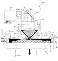
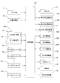
- FIG. 1 is a block diagram showing the overall configuration of the modeling system 100 according to the first embodiment.
- the modeling system 100 is a DED M3DP.
- the modeling system 100 can also be used to form a three-dimensional structure on a stage, which will be described later, by rapid prototyping, but performs additional processing by three-dimensional modeling on a workpiece (for example, an existing part). Can also be used. In the present embodiment, the description will be made centering on the case of performing additional machining on the latter workpiece.
- the modeling system 100 includes a moving device 200, a measuring device 400, a modeling head unit 500, and a control device 600 that controls the entire modeling system 100 including these units.
- the measuring device 400 and the modeling head unit 500 are arranged apart from each other in a predetermined direction. In the following description, for convenience, it is assumed that the measuring device 400 and the modeling head unit 500 are arranged apart from each other in the X-axis direction (see FIG. 2) described later.
- FIG. 2 shows the modeling head unit 500 together with the stage 12 constituting a part of the moving device 200.
- a work W is mounted on a table, which will be described later, included in the stage 12.
- a workpiece for example, an existing part
- a workpiece including a workpiece that is undergoing additional processing
- FIG. 2 shows a state during the additional machining for the workpiece W. In the following, the direction orthogonal to the paper surface in FIG.
- the rotation (tilt) direction will be described as ⁇ x, ⁇ y, and ⁇ z directions, respectively.
- the moving device 200 changes the position and orientation of the modeling target surface (here, the surface on which the target part TA on the workpiece W is set) TAS (see FIGS. 2 and 5). Specifically, the target 12 is moved by moving the stage 12 on which the workpiece W having the target surface TAS is mounted in, for example, directions of six degrees of freedom (X-axis, Y-axis, Z-axis, ⁇ x, ⁇ y, and ⁇ z directions). The position of the surface in the direction of 6 degrees of freedom is changed.
- positions of the three degrees of freedom in the ⁇ x, ⁇ y, and ⁇ z directions of the stage, workpiece, or target surface are collectively referred to as “posture” as appropriate, and the remaining three degrees of freedom directions (X The positions of the axis, the Y-axis, and the Z-axis direction) are collectively referred to as “positions” as appropriate.
- the moving device 200 includes a stage 12 that can move in the direction of six degrees of freedom and a drive mechanism 14 that moves the stage 12.
- the drive mechanism of the stage 12 includes an articulated robot that can freely move on a floor surface parallel to the XY plane. Below, the drive mechanism 14 of the stage 12 is also called the robot 14 (refer FIG. 6) for convenience.
- the stage 14 can be moved by the robot 14 with a predetermined stroke in each of the X-axis, Y-axis, and Z-axis directions, and can be moved minutely in the remaining three degrees of freedom.
- the position information of the stage 12 in the direction of at least 6 degrees of freedom is based on detection information of various sensors (various sensors (referred to as a sensor group 17) for detecting the rotation angle of the joint or the amount of expansion / contraction of the arm) provided in the robot 14. Required (see FIG. 6). Although the sensor group 17 is provided in the robot 14, the sensor group 17 is shown separately from the robot 14 in FIG. 6 for convenience of explanation.
- the drive mechanism 14 of the stage 12 is not limited to a robot, and may be a mechanism including a parallel link mechanism in which the stage 12 constitutes an end effector and a planar motor or linear motor that moves the parallel link mechanism in the XY plane. There may be. Further, the drive mechanism 14 is not limited to one that can move the stage 12 in the direction of 6 degrees of freedom, as long as the stage 12 can be moved in the direction of at least 3 degrees of freedom of the X axis, the Y axis, and the Z axis.
- the stage 12 includes a table 12a having a rectangular shape in plan view on which the workpiece W is mounted, and a frame member 12b having a predetermined height in a rectangular shape in plan view fixed to the upper surface of the table 12a.
- the workpiece W is fixed on the table using a chuck member (not shown) made of a mechanical chuck or a vacuum chuck.
- the frame member 12b is joined to the upper surface of the table 12a without a gap, and a rectangular tank 13 in plan view with the frame member 12b as a peripheral wall is formed by the frame member 12b and the upper surface of the table 12a.
- the table 12a and the frame member 12b may be a single member.
- the tank 13 may be called a pool or a reservoir.
- the tank 13 can store the cooling water CW therein.
- a hole (not shown) penetrating the frame member 12b in the Y-axis direction is formed in a portion on the + Y side of the frame member 12b constituting the peripheral wall of the tank 13, and a drain pipe 16 is connected to the hole via a connector 15. Is connected.
- the connector 15 has a first portion 15a provided on the stage 12 and a second portion 15b provided at one end of the drain pipe 16, and the second portion 15b can be attached to the first portion 15a.
- the waiting second portion 15b is a first portion provided on the stage 12. It is attached to 15a, and one end of the drain pipe 16 is connected to the tank 13 (stage 12). Note that the drain pipe 16 may be connected to the stage 12 without providing the connector 15. Further, the stage 12 may be moved while the drain pipe 16 is connected to the stage 12.
- the drain pipe 16 is provided with a first flow rate control valve 18A (not shown in FIG. 2, refer to FIG. 6) capable of adjusting the flow rate of the liquid flowing through the internal flow path.
- the first flow rate control valve 18A can function as a stop valve because the flow path inside the drain pipe 16 can be fully closed.
- the first flow control valve 18A is controlled by the control device 600.
- an outlet unit 20 having a supply port 20a provided on one end side of the water supply pipe 19 is disposed at a predetermined height.
- the outlet unit 20 is oriented in a direction perpendicular to the Z axis (in this embodiment, Y in the present embodiment) by a first drive unit 22A (not shown in FIG. 2, see FIG. 6). It can be reciprocated along the axial direction.
- the outlet unit 20 may not be movable, and may move in another direction (for example, the Z-axis direction) in addition to the direction perpendicular to the Z-axis or instead of the direction perpendicular to the Z-axis. It may be.
- a cooling water supply device 21 Connected to the other end of the water supply pipe 19 is a cooling water supply device 21 (not shown in FIG. 2, refer to FIG. 6) including a liquid tank containing cooling water therein. Further, the water supply pipe 19 is provided with a second flow rate control valve 18B (see FIG. 6) having the same function as the first flow rate control valve 18A. The second flow control valve 18B is controlled by the control device 600.
- an aerial ultrasonic water level sensor (hereinafter referred to as “water level”) that detects the level (water level) of the cooling water CW in the tank 13 at a predetermined height.
- the water level sensor 26 is a set of a speaker, a microphone, and a thermometer. From the time until the sound radiated from the speaker is reflected by the water surface (liquid level) and reaches the microphone, the water level (liquid level) is measured. Calculate the distance to the water level (liquid level). The thermometer is for correcting (temperature compensation) that the speed of sound is affected by temperature.
- the sensor is not limited to the ultrasonic water level sensor, and any type of sensor may be used as long as it can detect the level (water level) of the water level (liquid level) of the cooling water in the tank 13.
- the water level sensor 26 is in a direction perpendicular to the Z axis (in this embodiment, Y in the present embodiment) by a second drive unit 22B (not shown in FIG. 2, see FIG. 6). It can be reciprocated along the axial direction.
- the water level sensor 26 may not be movable, and may be movable in the Z-axis direction in addition to the direction perpendicular to the Z-axis or in place of the direction perpendicular to the Z-axis.
- the first drive unit 22A and the second drive unit 22B are controlled by the control device 600 as necessary, thereby interlocking with the change in the position of the stage 12 in the Y-axis direction,
- the outlet part 20 and the water level sensor 26 move in the Y-axis direction.
- control is performed so that the water surface (liquid surface) of the cooling water CW is positioned at a position higher than the target surface TAS of the workpiece W mounted on the stage 12 (table 12a) during modeling.
- the apparatus 600 controls the first and second flow control valves 18A and 18B based on the measurement information of the water level sensor 26. This will be further described later.
- the position and posture of the work (stage 12) are controlled with respect to the beam from the irradiation unit.
- the beam from the beam irradiation unit may be movable, or both the beam and the workpiece (stage) may be movable.
- the moving device 200 includes a position measurement system 28 (see FIG. 6) that measures position information regarding the X-axis direction and the Y-axis direction of the robot 14. Measurement information of the position measurement system 28 is sent to the control device 600.
- position information in this embodiment, in the three-dimensional space of at least a part of the target surface TAS (for example, the upper surface) on the workpiece W mounted on the stage 12 by the measuring device 400.
- Shape information is measured, and after the measurement, additional processing (modeling) is performed on the workpiece W.
- the control device 600 measures the shape information of at least a part of the target surface on the workpiece W, the measurement result, detection information of the sensor group 17 (various sensors included in the robot 14) at the time of measurement,
- the position and orientation of the target surface on the workpiece W mounted on the stage 12 are referred to as a reference coordinate system (hereinafter referred to as a stage coordinate system) of the modeling system 100.
- a stage coordinate system of the modeling system 100.
- 6 degrees of freedom with respect to the target portion of the target surface TAS on the workpiece W is controlled by open loop control of the position and posture of the stage 12 based on the detection information of the sensor group 17 and the measurement result of the position measurement system 28.
- Position control with respect to direction is possible.
- an absolute encoder that does not need to return to the origin is used as the sensor group 17 and the position measurement system 28, so that the reset is easy. It should be measured by the measuring device 400 used to enable position control in the 6 degrees of freedom direction with respect to the target portion of the target surface on the workpiece W by open loop control of the position in the 6 degrees of freedom direction of the stage 12.
- the above-described position information in the three-dimensional space is not limited to the shape, and it is sufficient if the position information is at least three points according to the shape of the target surface.
- the measuring device 400 measures the three-dimensional position information of the workpiece for associating the position and posture of the workpiece mounted on the stage 12 with the stage coordinate system, for example, the shape.
- the measuring device 400 includes a laser non-contact type three-dimensional measuring machine 401, for example.
- the three-dimensional measuring instrument 401 is configured in the same manner as the shape measuring apparatus disclosed in, for example, US Patent Application Publication No. 2012/0105867.
- a line-shaped projection pattern composed of one line light is projected onto the surface of the test object, and the line-shaped projection pattern Each time the entire surface of the test object is scanned, the line-shaped projection pattern projected onto the test object is imaged from an angle different from the projection direction. Then, the height from the reference plane of the surface of the test object is calculated from the captured image of the surface of the test object for each pixel in the longitudinal direction of the linear projection pattern using the principle of triangulation, etc. Find the three-dimensional shape of the surface.
- the scanning of the line light in the direction parallel to the X and Y planes with respect to the test object is performed by the movement of the sensor unit in the apparatus described in US 2012/0105867.
- This embodiment is different in that it is performed by moving the stage 12.
- the above-described scanning may be performed by moving the sensor unit or by moving both the sensor unit and the stage 12.
- the measuring apparatus 400 may include a mark detection system 56 (see FIG. 6) that optically detects an alignment mark instead of the above-described three-dimensional measuring device 401 or in addition to the above-described three-dimensional measuring device. .
- the mark detection system 56 can detect, for example, an alignment mark formed on the workpiece.
- the control device 600 calculates the position and orientation of the workpiece (or stage 12) by accurately detecting the center positions (three-dimensional coordinates) of at least three alignment marks using the mark detection system 56, respectively.
- the mark detection system 56 can be configured to include a stereo camera, for example.
- the mark detection system 56 may optically detect at least three alignment marks formed in advance on the stage 12.
- the control device 600 scans the surface (target surface) of the workpiece W with respect to the line light from the three-dimensional measuring device 401 as described above, and acquires the surface shape data. Then, the control device 600 performs a least square process using the surface shape data, and associates the three-dimensional position and orientation of the target surface on the workpiece with the stage coordinate system.
- the position of the stage 12 in the direction of 6 degrees of freedom is managed on the stage coordinate system by the control device 600.
- the stage 12 in accordance with the stage coordinate system is used for all control of the position (ie, position and orientation) of the workpiece W in the direction of six degrees of freedom, including the time of additional machining by three-dimensional modeling. This can be done by open loop control.
- the modeling head unit 500 includes a light source system 510 and a condensing optical system 82, and is inclined in the YZ plane with respect to the optical axis AX via the condensing optical system 82 (terminal lens 82a).
- a beam irradiation unit 520 that emits the beams LB 1 and LB 2 , a material supply unit 530 that supplies a powdery modeling material PD, and a cover member connected to the lower end of the lens barrel 85 that holds the condensing optical system 82 30 and a gas supply device 40 (see FIG. 6) for supplying an inert gas such as nitrogen (N 2 ) to the first space 30a (see FIG. 5) inside the cover member 30 via a gas supply port described later.
- N 2 nitrogen
- the light source system 510 includes, for example, a light source unit 60 including a plurality of laser units (not shown in FIG. 2, refer to FIG. 6), an illuminance uniformizing optical system (not shown) including a double fly-eye optical system, a condenser lens system, and the like. And using a uniform illumination optical system, the beams respectively emitted from the plurality of laser units are mixed to generate a parallel beam with a uniform cross-sectional illumination distribution.
- the configuration of the illuminance uniforming optical system is not particularly limited.
- the illuminance uniforming optical system may be configured using a rod integrator, a collimator lens system, or the like.
- the light source unit 60 (a plurality of laser units) of the light source system 510 is connected to a control device 600 (see FIG. 6), and on / off of the plurality of laser units is individually controlled by the control device 600. Thereby, the light quantity (laser output) of the laser beam irradiated to the workpiece
- work W upper target surface
- the modeling system 100 may not include a light source or a light source and an illuminance uniforming optical system.
- a parallel beam having a desired light amount (energy) and desired illuminance uniformity may be supplied to the modeling system 100 from an external device.
- the beam irradiation unit 520 includes, in addition to the light source system 510, a beam cross-sectional intensity conversion optical system 78 and a spatial light modulator (SLM) that are sequentially arranged on the optical path of the parallel beam from the light source system 510.
- a mirror array 80 which is a kind of Spatial (Light Modulator) and a condensing optical system 82 for condensing light from the mirror array 80.
- the spatial light modulator is a general term for elements that spatially modulate the amplitude (intensity), phase, or polarization state of light traveling in a predetermined direction.
- the beam cross-sectional intensity conversion optical system 78 converts the cross-sectional intensity distribution of the parallel beam from the light source system 510.
- the beam cross-section intensity conversion optical system 78 converts the parallel beam from the light source system 510 into a donut-shaped (annular) parallel beam in which the intensity of the region including the center of the cross-section is substantially zero.
- the beam cross-section intensity conversion optical system 78 is constituted by, for example, a convex cone reflector and a concave cone reflector that are sequentially arranged on the optical path of the parallel beam from the light source system 510.
- the parallel beam from the light source system 510 is reflected radially by the reflecting surface of the convex cone reflector, and the reflected beam is reflected by the reflecting surface of the concave cone reflector, thereby being converted into an annular parallel beam. .
- the parallel beam that has passed through the beam cross-sectional intensity conversion optical system 78 is irradiated onto the workpiece via a mirror array 80 and a condensing optical system 82 as described later.
- the beam cross-sectional intensity conversion optical system 78 By converting the cross-sectional intensity distribution of the parallel beam from the light source system 510 using the beam cross-sectional intensity conversion optical system 78, the intensity of the beam incident on the pupil plane (incident pupil) PP of the condensing optical system 82 from the mirror array 80. It is possible to change the distribution. Further, by converting the cross-sectional intensity distribution of the parallel beam from the light source system 510 using the beam cross-sectional intensity conversion optical system 78, the emission of the beam substantially emitted from the condensing optical system 82 is emitted. It is also possible to change the intensity distribution on the surface.
- the beam cross-sectional intensity conversion optical system 78 is not limited to a combination of a convex conical reflector and a concave conical reflector.
- the diffractive optical element disclosed in US Patent Application Publication No. 2008/0030852 A combination of a focal lens and a conical axicon system may be used.
- the beam cross-sectional intensity conversion optical system 78 may be any one that converts the cross-sectional intensity distribution of the beam, and various configurations are conceivable.
- the intensity of the parallel beam from the light source system 510 in the region including the center of the cross-section is not substantially zero, It is also possible to make it smaller than the intensity in the region.
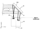
- the mirror array 80 includes a base member 80A having a plane (hereinafter referred to as a reference plane for convenience) that forms 45 degrees ( ⁇ / 4) with respect to the XY plane and the XZ plane, and a base member 80A.
- a reference plane for convenience
- a drive unit 87 (not shown in FIG. 2, refer to FIG. 6) including M actuators (not shown) that individually drive 81 p and q .
- the mirror array 80 adjusts the inclination of a large number of mirror elements 81 p, q with respect to the reference plane (for example, by making the reflection surfaces of all the mirror elements 81 p, q substantially parallel to the reference plane).
- a large reflective surface parallel to the surface can be formed substantially.
- each mirror element 81p , q of the mirror array 80 is, for example, rectangular.
- Each mirror element 81 p, q of the mirror array 80 for example, each mirror element 81 p, rotatable in the one axis of rotation parallel to the diagonal line of the reflecting surface of q, inclined with respect to the reference plane of the reflecting surface
- the angle can be set to an arbitrary angle within a predetermined angle range.
- the angle of the reflecting surface of each mirror element is measured by a sensor that detects the rotation angle of the rotating shaft, for example, a rotary encoder 83 p, q (not shown in FIG. 2, see FIG. 6).
- the drive unit 87 includes, for example, an electromagnet or a voice coil motor as an actuator, and each mirror element 81 p, q is driven by the actuator and operates with a very high response.
- each of the mirror elements 81p and q illuminated by the annular parallel beam from the light source system 510 has a reflected beam in a direction according to the inclination angle of its reflecting surface. (Parallel beam) is emitted and incident on the condensing optical system 82 (see FIG. 3).
- the cross-sectional shape (cross-sectional intensity distribution) of the parallel beam incident on the mirror array 80 may be different from the annular shape.
- the beam may be irradiated to the beam.
- the beam cross-sectional intensity conversion optical system 78 may not be provided.
- Condensing optical system 82 has a numerical aperture of N.P. A. Is, for example, 0.5 or more, preferably 0.6 or more. A. Thus, it is a low aberration optical system.
- the condensing optical system 82 includes one or a plurality of large-diameter lenses including a terminal lens 82a held by a cylindrical lens barrel 85 (in FIG. 2, etc., the terminal lens 82a is representative). (Illustrated).
- a lens referred to as a hollow lens for convenience
- having a hollow portion (through hole) TH penetrating in the optical axis AX direction at the center including the optical axis AX is used as the terminal lens 82a.
- the lenses other than the terminal lens 82a may be a hollow lens or may not be a hollow lens.
- the condensing optical system 82 has a large aperture, low aberration, and high N.P. A. Therefore, a plurality of parallel beams from the mirror array 80 can be collected on the rear focal plane.
- the beam irradiation unit 520 can condense the beam emitted from the condensing optical system 82 (terminal lens 82a) into, for example, a spot shape (or a slit shape).
- the condensing optical system 82 is composed of one or a plurality of large-diameter lenses, the area of incident light can be increased, and thereby the numerical aperture N.P. A. As compared with the case of using a condensing optical system having a small size, a larger amount of light energy can be taken in. Therefore, the beam condensed by the condensing optical system 82 according to the present embodiment is extremely sharp and has a high energy density, which makes it possible to increase the processing accuracy of the additional processing.
- the stage 12 is moved in a scanning direction parallel to the XY plane (in FIG. 2, as an example, the Y-axis direction), whereby a beam and a workpiece W having a modeling target surface TAS are obtained.
- a scanning direction parallel to the XY plane in FIG. 2, as an example, the Y-axis direction
- a beam and a workpiece W having a modeling target surface TAS are obtained.
- the stage 12 may be moved in at least one of the X-axis direction, Z-axis direction, ⁇ x direction, ⁇ y direction, and ⁇ z direction while the stage 12 is moving in the Y-axis direction. Needless to say.
- the powdery modeling material (metal material) supplied by the material supply unit 530 is melted by the energy of the beam (laser beam). Therefore, as described above, if the total amount of energy taken in by the condensing optical system 82 increases, the energy of the beam emitted from the condensing optical system 82 increases, and the amount of metal that can be dissolved per unit time increases. Accordingly, if the supply amount of the modeling material and the speed of the stage 12 are increased, the throughput of the modeling process is improved.
- the modeling target surface TAS is aligned with a predetermined surface (hereinafter referred to as a modeling surface MP) (see, for example, FIG. 2).
- a modeling surface MP a predetermined surface
- a spot-shaped beam irradiation region (beam spot) is formed on the modeling surface MP, and the workpiece W (target surface TAS) is made relative to the beam (spot beam) that forms the beam spot.
- Modeling processing can be performed while scanning.
- the control device 600 performs position control of the target surface TAS of the workpiece W in the direction of six degrees of freedom by the above-described open loop control when modeling for additional processing on the workpiece.
- the target surface TAS is controlled to be perpendicular to the optical axis AX.
- the control device 600 lowers the stage 12 in the ⁇ Z direction by a predetermined distance (corresponding to the thickness of each layer) every time the shaping of each layer is completed. In parallel with this, the liquid level of the cooling water CW is reduced.
- the first and second flow control valves 18A and 18B are controlled to enter the tank 13 so as to be maintained at a position that is a predetermined distance higher (slightly higher) than the target surface TAS.
- the supply amount of the cooling water CW from the outlet part 20 and the drainage amount of the cooling water CW from the tank 13 through the drain pipe are controlled. More specifically, the control device 600 presets a target surface TS (see FIG. 2) where the coolant level should be aligned at a position higher than the modeling surface MP by a predetermined distance.
- the above-described modeling surface MP is the rear focal plane of the condensing optical system 82 (see, for example, FIG. 2), but the modeling plane may be a plane near the rear focal plane.
- the modeling surface MP is perpendicular to the optical axis AX on the exit side of the condensing optical system 82, but may not be perpendicular.
- the light enters the condensing optical system 82.
- a method of controlling the incident angle distribution of a plurality of parallel beams can be employed.
- the condensing optical system 82 of this embodiment has a configuration in which the pupil plane (incidence pupil) PP and the front focal plane coincide, the incident angles of a plurality of parallel beams LB using the mirror array 80 are used.
- the converging position of the plurality of parallel beams LB can be controlled accurately and simply, but the pupil plane (incident pupil) of the condensing optical system 82 and the front focal plane are not matched. May be.
- the mirror array 80 is employed, and the control device 600 operates each mirror element 81 p, q with a very high response, thereby allowing a plurality of parallel rays incident on the pupil plane PP of the condensing optical system 82.
- the incident angle of the beam LB is controlled.
- the intensity distribution of the beam on the modeling surface MP can be set or changed.
- the control device 600 is on the modeling surface MP during the relative movement between the beam and the target surface TAS (the surface on which the modeling target portion TA is set, which is the surface on the workpiece W in this embodiment). It is possible to change the intensity distribution of the beam, for example, at least one of the shape, size and number of the irradiation region of the beam.
- control device 600 can change the intensity distribution of the beam on the modeling surface MP continuously or intermittently.
- the control device 600 can also change the intensity distribution of the beam on the modeling surface MP according to the relative position between the beam and the target surface TAS.
- the control device 600 can also change the intensity distribution of the beam on the modeling surface MP according to the required modeling accuracy and throughput.
- the control device 600 detects the state of each mirror element (here, the inclination angle of the reflecting surface) using the rotary encoder 83 p, q described above, and thereby the state of each mirror element is determined. Since the monitoring is performed in real time, the inclination angle of the reflecting surface of each mirror element of the mirror array 80 can be accurately controlled.
- a pupil surface of the condensing optical system 82 is used instead of the mirror array 80 by using a solid mirror having a desired shape. It is also possible to change the position of the irradiation region by controlling the incident angle of one parallel beam incident on.
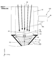
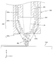
- FIG. 4 shows the condensing optical system 82 of the modeling head unit 500 and the lower part thereof as viewed from the ⁇ Y direction and partially omitted.
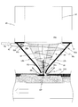
- FIG. 5 shows the lens barrel 85 in FIG. 2 and the lower portion thereof in an enlarged manner together with the vicinity of the target portion TA on the workpiece W.
- the material supply unit 530 includes a supply tube 84 that extends in the Z-axis direction and is disposed in the hollow portion TH of the terminal lens 82 a of the condensing optical system 82 along the optical axis AX. And a material supply device 86 connected to one end (upper end) of 84 via a pipe 90a.
- a material supply port 84 a is formed at the other end (lower end) of the supply pipe 84, and the material supply port 84 a is disposed in the first space 30 a inside the cover member 30.
- the supply pipe 84 is disposed in the hollow portion TH of the terminal lens 82a, and a gap between the outer peripheral surface of the supply pipe 84 and the inner surface of the hollow portion TH of the terminal lens 82a is a seal member 89. Is sealed by. Therefore, as shown in FIG. 5, the first space 30a inside the cover member 30 below the terminal lens 82a is separated from the space (second space) 85a inside the lens barrel 85 above the terminal lens 82a. Thus, inflow of gas from the first space 30a to the second space 85a is prevented. In addition, you may make it the structure which can pass gas in the hollow part TH of the terminal lens 82a, without providing the sealing member 89.
- FIG. 5 shows a gap between the outer peripheral surface of the supply pipe 84 and the inner surface of the hollow portion TH of the terminal lens 82a. Is sealed by. Therefore, as shown in FIG. 5, the first space 30a inside the cover member 30 below the terminal lens 82a is separated from the space (second space) 85a inside the lens
- the pressure in the upper space (second space 85a inside the lens barrel 85) of the terminal lens 82a is made higher than the pressure in the lower space (first space 30a) of the terminal lens 82a, so that the hollow of the terminal lens 82a is increased.
- the portion TH may be configured so that no gas flows from the exit surface side toward the entrance surface side.
- gas ininert gas or the like
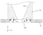
- the cover member 30 is composed of a hollow conical member (a plate member having a substantially uniform thickness having conical surfaces on the outer surface and the inner surface), and the bottom surface (the upper side in FIG. 5).
- a mounting portion 31 having an annular shape in plan view is provided on the surface.
- the attachment portion 31 is formed of an annular plate member whose inner diameter is smaller than the bottom surface of the cover member 30 (slightly larger than the outer diameter of the terminal lens 82 a) and whose outer diameter is slightly larger than the bottom surface of the cover member 30.
- the cover member 30 is fixed to the lower end surface of the lens barrel 85 via the attachment portion 31. That is, the cover member 30 is suspended and supported by the lens barrel 85.
- an exit 30b of the beam (LB 1 , LB 2 ) irradiated to the target surface TAS is formed at the distal end.
- a vibration isolating member such as rubber
- the cover member 30 may be supported by a support member different from the lens barrel 85.
- the material supply device 86 includes a cartridge in which the modeling material PD is accommodated, and the modeling material PD in the cartridge is discharged from the material supply port 84 a via the pipe 90 a and the supply pipe 84.
- Toward 30b for example, it is dropped freely, or it is dropped by pushing it at a predetermined pressure, and supplied onto the target surface along the optical axis AX.
- the modeling material PD When the modeling material PD is dropped as described above, the modeling material usually diffuses as it goes down (as it approaches the tip of the cover member 30), and the distance from the lower end of the supply pipe 84 to the target surface TAS is a predetermined distance or more. If it exists, it will spread
- the conical surface shape of the inner surface 30c of the cover member 30 is used, and a spiral swirling flow indicated by reference numeral SF in FIG. 5 is generated along the inner surface of the conical surface.
- the aforementioned gas supply device 40 (see FIG. 6) for supplying nitrogen, which is a kind of inert gas, to the internal space (first space) 30a of the cover member 30 is provided.
- the gas supply device 40 replaces nitrogen with a rare gas that is a kind of inert gas (for example, helium (He), neon (Ne), argon (Ar), etc.), nitrogen, and at least one kind of rare gas.
- a mixed gas of a plurality of kinds of rare gases may be supplied into the first space 30a.
- an opening 30d for connecting the gas supply pipe 42 shown in FIG. 5 is formed.
- One end of a gas supply pipe 42 is connected to the opening 30d. More specifically, one end of the gas supply pipe 42 covers, for example, the tangential direction of the inner surface 30c of the cover member 30 so as to intersect the wall of the cover member 30 at an acute angle in plan view (viewed from above).
- the gas supply port 42a at the tip of the gas supply pipe 42 is inserted into the opening 30d formed in the member 30 from the outside, and is exposed in the first space 30a inside the cover member 30. In this case, the gas supply port 42 a is located above the center in the height direction of the cover member 30. Further, the gas supply port 42a is located at a position higher than the material supply port 84a.
- one end portion of the gas supply pipe 42 is slightly inclined with respect to the XY plane so that one end side is lower than the other end side in a state of being inserted into the opening 30d of the cover member 30. That is, the above-described opening 30d is formed in the cover member 30 in a direction that intersects the inner surface 30c of the cover member 30 at an acute angle in a plan view and is slightly inclined with respect to the XY plane.
- the other end of the gas supply pipe 42 is connected to a gas supply device 40 (see FIG. 6).
- a gas supply device 40 for example, along the conical inner surface 30 c of the cover member 30 via the gas supply port 42 a of the gas supply pipe 42, for example, the tangent line of the inner surface 30 c of the cover member 30.
- nitrogen in the operating state of the gas supply device 40, for example, along the conical inner surface 30 c of the cover member 30 via the gas supply port 42 a of the gas supply pipe 42, for example, the tangent line of the inner surface 30 c of the cover member 30.
- nitrogen in the operating state of the gas supply device 40, for example, along the conical inner surface 30 c of the cover member 30 via the gas supply port 42 a of the gas supply pipe 42, for example, the tangent line of the inner surface 30 c of the cover member 30.
- nitrogen in the operating state of the gas supply device 40, for example, along the conical inner surface 30 c of the cover member 30 via the gas supply
- the static pressure decreases as it approaches the center according to Bernoulli's theorem (except for the vicinity of the center where the influence of viscosity is strong).
- the diameter of the inner surface 30c of the cover member 30 is smaller as it goes downward (as it approaches the outlet 30b of the cover member 30). Therefore, the cover member 30 functions as a convergent nozzle (convergent nozzle) for accelerating the fluid, and the closer to the narrow portion (the front end portion of the cover member 30), the faster the flow rate of the gas flowing inside the cover member 30 is. The pressure is lowered.
- the static pressure in the swirling flow SF is lowest at the center of the position of the outlet 30b of the cover member 30.
- the powdery modeling material PD falling right below the supply pipe 84 is closer to the bottom (as it approaches the outlet 30b of the cover member 30), and the inner surface of the cover member 30 due to the swirling flow of nitrogen (inert gas). It is narrowed down corresponding to the shape of 30c. Therefore, in the operating state of the gas supply device 40, the powdery modeling material PD supplied from the supply pipe 84 can be converged to almost one point (here, a point on the optical axis AX), and the modeling material PD is beamed.
- the gas supply device 40 can adjust the temperature, flow rate, and the like of the inert gas sent into the first space 30a.
- the opening 30d provided in the cover member 30 may be used as a gas supply port.
- the tip of the gas supply pipe 42 may be connected to the opening 30d of the cover member 30 so as not to be exposed to the first space 30a.
- gas supply port 42 a (opening 30 d) may be disposed below the center in the height direction of the cover member 30. Further, the gas supply port 42a (opening 30d) may be disposed below the material supply port 84a.
- the liquid level (water surface) of the cooling water CW is set at a position higher than the target surface TAS of the workpiece W during modeling.
- the cooling water CW may be adversely affected and the desired modeling accuracy may not be ensured. Therefore, in the modeling system 100, as shown in FIG. 2 and FIG. 5, the inert gas ejected from the outlet 30b at the tip of the cover member 30 is supplied toward the target portion TA after becoming the above-described swirl flow SF. To do.
- the flow of the inert gas causes the target surface TAS including the target portion TA to be on the target surface TAS.
- the cooling water CW existing on a partial area can be blown off and removed.
- a partial region including the target portion TA is locally set in a non-immersion state (dry state), and the local non-immersion state, that is, the target surface TAS is covered with the supplied cooling water CW.
- the modeling material PD is supplied to the target region and the beam is irradiated, and the target region TA is modeled. Therefore, it is possible to produce a three-dimensional structure that ensures excellent modeling accuracy and high resolution without being affected by cooling water.
- the beam irradiation region on the modeling surface MP is formed by the beams LB 1 and LB 2 emitted through the outlet 30b, so that the beam is formed on the modeling surface.
- the range in which the shape, size, or position of the irradiated region can be changed is limited by the shape and size of the outlet 30b.
- the gas supply port 42a is provided at a position substantially the same height as the lower surface of the terminal lens 82a, so that the terminal lens 82a is driven by a high-speed inert gas flow.
- the terminal lens 82a can be protected from contamination (including adhesion of a modeling material from the material supply port 84a).
- the end lens 82a is physically protected by the cover member 30, it is protected from contamination by contaminants in the atmosphere outside the cover member 30.
- the material supply device 86 includes, for example, two powder cartridges, and each of the two powder cartridges contains powder of a first modeling material (for example, titanium) and a second modeling material (for example, stainless steel). .
- the material supply device 86 includes two powder cartridges for supplying two types of modeling materials.
- the material supply device 86 may include only one powder cartridge.
- the material supply device 86 is connected to the control device 600 (see FIG. 6), and 2 2 by the material supply device 86 (internal control unit) in response to an instruction from the control device 600 during modeling.
- One of the two powder cartridges is selected, and the modeling material from the selected powder cartridge is supplied to the supply pipe 84 via the pipe 90a.
- the supply pipe 84 may be supplied.
- the control device 600 can adjust the supply amount of the modeling material supplied to the supply pipe 84 from the powder cartridge selected by the material supply device 86 per unit time.
- the adjustment of the supply amount of the modeling material supplied to the supply pipe 84 per unit time is to obtain a negative pressure on the outside of the powder cartridge with respect to the inside when acquiring the powder from the powder cartridge. It can be performed by adjusting, or by providing a valve for adjusting the amount of powder supplied from the material supply device 86 to the pipe 90a and adjusting the opening of the valve.
- the reflected beam from the mirror array 80 is a partial region (partial region having a large NA) in the vicinity of the periphery of the condensing optical system 82.
- the shaping surface MP of the condensing optical system 82 through the region of the peripheral edge away from the optical axis AX of the terminal lens 82a located at the exit end of the condensing optical system 82, that is, the exit end of the beam irradiation unit 520.
- the light is condensed on the rear focal plane of the condensing optical system 82) (see FIG. 2).
- a beam spot is formed only by light passing through a portion near the periphery of the same condensing optical system 82. For this reason, it is possible to form a high-quality beam spot as compared with the case where a beam spot (laser spot) is formed by condensing light through different optical systems in the same region.
- the irradiation of the beam to the supply pipe 84 disposed in the hollow portion TH of the terminal lens 82a of the condensing optical system 82 and the pipe 90a having one end connected to the upper end of the supply pipe 84 is limited. be able to.
- the mirror array 80 is illuminated by an annular parallel beam.
- a limiting member 92 indicated by a two-dot chain line in FIG. 4 is provided on the incident surface side (for example, pupil plane PP) of the condensing optical system 82. May be provided.
- the limiting member 92 limits the incidence of the beam from the condensing optical system 82 on the supply tube 84.
- a light shielding member may be used, but a neutral density filter or the like may be used.
- the parallel beam incident on the condensing optical system 82 may be a parallel beam having a circular cross section or an annular parallel beam. In the latter case, since the beam is not irradiated on the limiting member 92, all the reflected beams from the mirror array 80 can be used for spot formation.
- the condensing optical system 82 terminal lens 82a
- the + Y side of the supply pipe 84 and ⁇ Beams (shown as beams LB1 1 and LB1 2 for convenience in FIGS. 2 and 5) that pass through the optical path on the Y side (front and rear in the scanning direction of the workpiece W (stage 12)) are collected directly below the supply pipe 84.
- the beam spot is formed on the modeling surface by being illuminated, and the modeling material PD passes through the outlet 30b of the cover member 30 along the optical axis AX with respect to the spot beam forming the beam spot. Supplied.
- a molten pool WP is formed immediately below the supply pipe 84.
- the molten pool WP is formed while the stage 12 is scanned in the scanning direction (+ Y direction in FIG. 5).
- a bead (melted and solidified metal) BE see FIG. 5
- the beams LB 1 and LB 2 shown in FIG . It may be a separate parallel beam reflected at q and incident on the pupil plane PP of the condensing optical system 82 at a different incident angle, or may be a part of the same parallel beam, for example, a parallel beam having a ring-shaped cross section. Also good.
- the width in the X-axis direction or the Y axis When the incident angles of the plurality of parallel beams LB incident on the condensing optical system 82 are adjusted so that the width in the direction, or the width in the X-axis direction and the width in the Y-axis direction are gradually narrowed, the beam is condensed.
- the density energy density increases.
- the thickness of the formed bead BE layer is kept constant, and the throughput is increased. Can be kept at a high level.
- the thickness of the bead BE layer to be formed can be kept constant by using other adjustment methods as well as the adjustment method.
- the laser output (the amount of energy of the laser beam) of at least one of the plurality of laser units according to the width in the X-axis direction, the width in the Y-axis direction, or the width in the X-axis direction and the width in the Y-axis direction. ) May be adjusted, or the number of parallel beams LB incident on the condensing optical system 82 from the mirror array 80 may be changed. In this case, the throughput is somewhat lower than the adjustment method described above, but the adjustment is simple.
- FIG. 6 is a block diagram showing the input / output relationship of the control device 600 that mainly configures the control system of the modeling system 100.
- the control device 600 includes a workstation (or a microcomputer) and the like, and comprehensively controls each component of the modeling system 100.
- the basic function of the modeling system 100 is to add a desired shape to an existing part (work) by three-dimensional modeling.
- the workpiece is input into the modeling system 100, and after a desired shape is accurately added, the workpiece is unloaded from the modeling system 100.
- the actual shape data of the added shape is sent from the control device 600 to an external device, for example, a host device.
- a series of operations performed in the modeling system 100 is roughly as follows.
- the stage 12 is at a predetermined loading / unloading position
- the workpiece is mounted on the stage 12 by the workpiece transfer system 300 (see FIG. 6).
- the stage 12 on which the workpiece W is mounted is moved below the measuring device 400 by the control device 600.
- the movement of the stage 12 is performed by the control device 600 driving the robot 14 in the X-axis direction (and Y-axis direction) on the floor surface based on the measurement information of the position measurement system 28. During this movement, the above-described reference state is maintained on the stage 12.
- the control device 600 uses the measurement device 400 to measure position information (shape information in this embodiment) in at least a part of the target surface TAS of the workpiece W on the stage 12 in the reference state in the three-dimensional space. Is done. Thereafter, based on this measurement result, the position of the target surface TAS on the workpiece W in the direction of six degrees of freedom can be managed by open-loop control on the stage coordinate system (reference coordinate system).
- the stage 12 on which the workpiece W on which the measurement of at least a part of the shape information of the target surface TAS has been measured is moved by the control device 600 toward the lower side of the modeling head unit 500 (the cover member 30). At this time, the first and second flow control valves 18A and 18B are fully closed.
- stage 12 moves along a predetermined path and reaches a predetermined position below the modeling head unit 500, the second portion 15b of the connector 15 connected to one end of the drain pipe 16 is moved to the stage as described above. 12 is attached to a first portion 15a provided at the end 12, and one end of the drain pipe 16 is connected to the tank 13 (stage 12).
- the control device 600 supplies the cooling water CW into the tank 13 until the liquid level (water surface) matches the target surface TS.
- the cooling water CW is supplied in the following procedure. That is, the control device 600 opens the second flow control valve 18B at a predetermined opening, and starts supplying the cooling water CW from the outlet unit 20 into the tank 13 while monitoring the measurement information of the water level sensor 26. . And if it confirms based on the measurement information of the water level sensor 26 that the liquid level of the cooling water CW corresponded to the target surface TS, the control apparatus 600 will make the 2nd flow control valve 18B into a fully closed state, and will be in the tank 13 inside. The supply of the cooling water CW from the outlet unit 20 is stopped. If additional processing is possible without being affected by the cooling water CW, the supply of the cooling water CW may not be stopped. In other words, the cooling water may be supplied from the outlet unit 20 in parallel with the additional processing.
- additional processing is performed by three-dimensional modeling to add a shape corresponding to 3D data to the workpiece on the stage 12.
- This additional processing is performed as follows, for example.
- the control device 600 converts the 3D CAD data of the shape to be added by the additional processing (the shape obtained by removing the shape of the workpiece to be subjected to the additional processing from the shape of the object created after the additional processing) to the data for three-dimensional modeling.
- the data is converted into STL (Stereo-Lithography) data, and data of each layer sliced in the Z-axis direction is generated from the three-dimensional STL data.
- the control device 600 controls the moving device 200 and the modeling head unit 500 to perform additional processing of each layer on the workpiece based on the data of each layer, and the beam spot in the local non-immersion state described above.
- the formation and the formation of the molten pool WP by supplying the modeling material PD from the supply pipe 84 to the spot beam are repeatedly performed from the first layer to the Nth layer while scanning the stage 12 in the scanning direction.
- the stage 12 is driven downward by a predetermined distance by the robot 14 based on an instruction from the control device 600.
- the control device 600 performs opening control (including opening and closing) of the second flow control valve 18B and the first flow control valve 18A based on the measurement information of the water level sensor 26, and the tank 13
- the amount of the cooling water CW is adjusted so that the liquid surface (water surface) coincides with the target surface TS (surface that is a predetermined distance higher than the modeling surface MP). That is, the liquid level of the cooling water CW is controlled according to the lowering of the stage 12 (and the progress of modeling) in this way. Note that the control of the position and orientation of the target surface on the workpiece during the additional machining is performed in consideration of the shape information of the target surface measured previously.
- the supply of the cooling water CW may not be stopped.
- the cooling water may be supplied from the outlet unit 20 in parallel with the additional processing.
- the target surface (for example, the upper surface) TAS on which the target part TA for the additional processing of the workpiece W is set is perpendicular to the optical axis of the condensing optical system 82 by adjusting the tilt of the stage 12. Assuming that the surface is a flat surface (a surface parallel to the XY plane), modeling with the scanning operation of the stage 12 is performed.
- the control device 600 When the formation of the Nth layer is completed, the control device 600 fully opens the first flow control valve 18A, and the cooling water CW in the tank 13 is drained to the outside through the drain pipe 16. After the drainage is completed, the control device 600 drives the stage 12 in a direction away from the drain pipe 16 fixed at a predetermined position, thereby disengaging the first member 15a and the second member 15b of the connector 15. The drain pipe 16 is removed from the stage 12. Then, the control device 600 moves the stage 12 on which the additional processed workpiece W is mounted to the aforementioned loading / unloading position.
- the control device 600 instructs the workpiece transfer system 300 to unload the workpiece.
- the workpiece transfer system 300 takes out the workpiece W that has undergone additional processing from the stage 12 (table 12a) and transfers it to the outside of the modeling system 100.
- the control device 600 gives an instruction to the robot 14, and the stage 12 is set to the reference state.
- the moving device 200 stands by in preparation for loading the next workpiece at the loading / unloading position.
- the usage of the modeling system 100 according to the present embodiment is not limited to this, and the stage 12 is similar to a normal 3D printer or the like. It is also possible to create a three-dimensional shape by modeling from nothing above. In this case, it is nothing but to perform additional processing on the work "None".
- the control device 600 uses the mark detection system 56 (see FIG. 6) included in the measurement device 400 to form at least three places formed in advance on the stage 12.
- the controller 600 supplies the modeling material DP irradiated with the beam while relatively moving the beam and the target surface TAS, Based on the data of the multi-layer laminated cross section so that the target portion TA in the partial area in the non-immersion state on the target surface TAS of the workpiece W placed in the tank 13 is shaped.
- the apparatus 200, the beam irradiation unit 520, and the material supply unit 530 are controlled. That is, in this way, additional processing by three-dimensional modeling or workpiece fabrication by three-dimensional modeling is performed on the workpiece W by a local non-immersion method.
- the target surface TAS (stage 12) is driven down by one layer each time the modeling of each layer is completed by the control device 600.
- the amount of the cooling water CW in the tank 13 is adjusted so that the liquid level of the cooling water CW in the tank 13 is slightly higher than the upper surface of the uppermost layer that has been shaped in conjunction with the lowering of the tank 12. That is, in this way, the liquid level of the cooling water CW in the tank 13 is adjusted in conjunction with the descent driving of the stage 12 and the progress of the modeling, and other than a part of the local non-immersion area including the target part. In the area, the entire work W is always covered with cooling water. Therefore, it is possible to effectively suppress the occurrence of warping of the workpiece caused by the temperature non-uniformity of the workpiece during modeling processing. In particular, the usefulness is high in the case of a thin workpiece.
- the powdered modeling material (metal material) PD supplied by the material supply unit 530 is melted by the energy of the laser beam.
- the gas supply device 40 is actuated by the control device 600, and the spiral swirl flow along the inner surface 30c of the cover member 30 through the gas supply port 42a of the gas supply pipe 42 (see FIG. Nitrogen (inert gas) is fed into the cover member 30 so as to generate (see reference numeral SF of 5). Due to the swirling flow of nitrogen (inert gas), the powdery modeling material PD supplied by dropping downward from the supply pipe 84 goes down (closer to the tip of the cover member 30), the cover member.
- the powdery modeling material PD supplied from the supply pipe 84 can be converged to almost one point (here, a point on the optical axis AX), and the modeling material PD is melted by the beams LB 1 and LB 2.
- the above-described modeling in the local non-immersion state is realized as follows. That is, in the modeling system 100, the inert gas ejected from the outlet 30b at the tip of the cover member 30 is supplied toward the target portion TA after becoming the above-described swirl flow SF. By increasing the flow rate of the inert gas supplied to the target portion TA, the coolant CW existing on a partial area on the target surface TA including the target portion TA is blown off by the flow of the inert gas. be able to. Thereby, a partial region including the target part TA is locally set to a non-immersion state (dry state), and modeling using the modeling material PD for the target part TA is performed in the non-immersion state. Therefore, it is possible to model or produce a three-dimensional modeled object with excellent modeling accuracy and high resolution without being affected by cooling water.
- the high N.D. A The condensing optical system 82 is composed of one or a plurality of large-diameter lenses, so that the area of incident light can be increased. A. As compared with the case of using a condensing optical system having a small size, a larger amount of light energy can be taken in. Therefore, the beam condensed by the condensing optical system 82 according to the present embodiment is extremely sharp and has a high energy density, so that the processing accuracy by modeling can be increased.
- the total amount of energy taken in by the condensing optical system 82 is increased, the energy of the beam emitted from the condensing optical system 82 is increased, and the amount of metal that can be dissolved per unit time is increased. Accordingly, if the supply amount of the modeling material and the speed of the stage 12 are increased, the throughput of the modeling process by the modeling head unit 500 is improved.
- the intensity distribution of the beam on the modeling surface MP is set or changed by controlling the incident angle distribution of a plurality of parallel beams incident on the condensing optical system 82. be able to.
- a modeled object can be formed on the target surface TAS of the workpiece W with high processing accuracy by, for example, rapid prototyping.
- the tank 13 is provided in the stage 12 and the liquid is supplied into the tank 13 in order to supply the cooling water CW (liquid) on the target surface TAS has been described.
- the liquid supply method is not limited to this.
- An explanation will be given of a case where an inert gas (gas) is supplied to the first space 30a inside the cover member 30 so as to generate the flow SF, and the inert gas is swirled and then flows out of the first space 30a. did.
- a part of the region including the target portion TA is locally non-immersed using the inert gas supplied from the outlet 30b of the cover member 30 during modeling. .
- a plurality of openings may be formed in the cover member 30 and the gas supply pipe 42 may be individually connected to each opening.
- a plurality of openings are formed on the circular bottom surface (upper surface in FIG. 5) of the cover member 30 so that the gas supply pipes 42 can be connected to the positions where the central angles are equiangular intervals. May be.
- nitrogen in the tangential direction of the cover member 30 from the gas supply ports 42a of the plurality of gas supply pipes 42, one swirl flow in the same direction (clockwise or counterclockwise) is generated. It's also good.
- an inert gas may be supplied or injected toward the target portion TA through the internal space of the cover member 30 without generating the swirl flow SF.
- the cover member has a shape that includes a curved surface in a part that converges from the side opposite to the outlet 30b toward the outlet 30b with respect to the Z-axis direction (direction parallel to the optical axis AX), for example, a conical or elliptical cone-shaped inner surface.
- the outer shape is not particularly limited. Further, the cover member may not be provided. For example, the cover member may not be provided as long as an inert gas (gas) can be supplied to a partial region including the target portion TA.
- the modeling head unit 500 has a lens (as a terminal lens 82a of the beam irradiation unit 520) in which a through-hole penetrating in the optical axis direction is formed in the center including the optical axis AX (
- the material supply unit 530 has a supply pipe 84 that is inserted into the through-hole of the terminal lens 82a and supplies the modeling material along the optical axis AX, and the beam irradiation unit 520 includes a supply pipe.
- the condensing optical system 82 of the beam irradiation unit 520 has a large aperture, low aberration, and high N.P. A. Therefore, for example, a beam spot is formed only by the light passing through the vicinity of the peripheral edge of the same condensing optical system 82, thereby condensing the light through the different optical systems in the same region. This is because it is considered that a high-quality beam spot can be formed as compared with the case of forming a (laser spot). Therefore, the terminal lens need not be a hollow lens.
- the target surface (for example, the upper surface) TAS on which the target portion TA for the additional processing of the workpiece W is set is perpendicular to the optical axis of the condensing optical system 82 by adjusting the tilt of the stage 12.
- the plane is a plane set as a plane (a plane parallel to the XY plane)
- the target portion TA is not always set on the plane. . That is, it is conceivable that the target portion TA is set in the uneven portion on the workpiece W, but even in such a case, as shown in FIG.
- the partial area can be set to the local non-immersion area NIS in the same manner as described above, and the same modeling process can be performed.
- the modeling head portion is not limited to the configuration as in the above embodiment.
- the modeling head unit may be, for example, a type that irradiates a beam along the optical axis of the beam irradiation unit and supplies a modeling material along a path inclined with respect to the optical axis.
- a cover member 230 shown in FIG. 8 can be used as the cover member.
- the cover member 230 has a cylindrical shape as a whole, and has an outlet 230b that also serves as an exit for the beam, an exit for the modeling material, and an exit for the inert gas at the lower end in FIG. More specifically, the cover member 230 has an opening 232 (internal space) extending from the lower end surface in FIG.
- Each of the cover member 230 has three parts, ie, a first part 232a, a second part 232b, and a third part 232c, each of which has an inner peripheral surface centering on the axis of the cylinder.
- the 1st part 232a consists of a cylindrical surface-shaped inner peripheral surface located in the uppermost part and extended in an up-down direction.
- the second portion 232b is formed of a tapered inner peripheral surface (a part of a conical surface) that extends downward continuously from the first portion 232a.
- the third portion 232 c is formed of a tapered inner peripheral surface (a part of a conical surface) that communicates with the second portion and reaches the lower end surface of the cover member 230.
- the diameter of the second portion 232b gradually decreases as it approaches the third portion 232c.
- the third portion 232c is separated from the second portion 232b, and thus has a larger diameter.
- An outlet 230b is formed by the openings at the lower ends of the third portion 232c and the second portion 232b of the opening 232.
- a cylindrical beam emitting portion 234 extending in the up and down direction that is slightly smaller than the first portion 232a is provided inside the first portion 232a.
- the inside of the beam emitting unit 234 is a path for the beam LB.
- a space between the beam emitting portion 234 and the first portion 232a of the opening 232 is a part of the supply path for the modeling material PD.
- the modeling material PD passes through the space between the beam emitting portion 234 and the first portion 232a and the second portion 232b (the internal space) of the opening 232 below the space from the outlet 230b to the optical axis of the beam irradiation portion. Then, it is supplied to the target portion below the cover member 230 from the direction inclined by a predetermined angle.
- a pair of inert gas supply paths 236 are further formed outside the first portion 232 a and the second portion 232 b of the opening 232.
- the supply path 236 is formed in, for example, an arc shape in a cross section perpendicular to the Z axis, and a lower end thereof opens to a part of the inner peripheral surface of the third portion 232 c of the opening 232.
- the modeling head unit has an N.P. A. Is used, and a normal lens that is not a hollow lens is used as a terminal lens of the condensing optical system.
- the case where the partial region including the target portion TA is brought into the non-immersion state by supplying the inert gas toward the target surface TAS supplied with the cooling water CW has been described.
- the method for setting a partial area on the target surface TAS to the non-immersion state is not limited to this.
- a cover member 330 shown in FIG. 9 may be used instead of the cover member 30 described above.
- the cover member 330 is formed of a cylindrical member having a conical inner surface 330c, and has an outlet 330b having a role equivalent to that of the outlet 30b of the cover member 30 described above on the lower surface, and the outlet at a position outside the lower surface outlet 330b.
- a gas supply port 332 including an annular (for example, annular) concave portion that surrounds 330b is formed.
- a suction port 334 formed of an annular (for example, annular) concave portion that is slightly larger than the gas supply port 332 is formed on the lower surface of the cover member 330 outside the gas supply port 332 with respect to the outlet 330b.
- the suction port 334 is connected to a suction device such as a vacuum pump (not shown) via a suction path (not shown).
- the gas supply port 332 is connected to a gas supply device (not shown) via a supply path (not shown).
- the gas supply device may eject the inert gas from the gas supply port 332 downward, or may eject a gas other than the inert gas, for example, compressed air.
- the cooling water CW, the gas ejected from the gas supply port 332 through the suction port 334 (and the inert gas flowing out from the outlet 330b), etc. are in the suction path. Is sucked out and discharged to the outside.
- a non-immersion space NIS in which no liquid exists is formed below the cover member 330 (see FIG. 9).
- a plurality of gas supply ports may be arranged in an annular shape instead of the annular gas supply port 332.
- a plurality of suction ports may be arranged in a ring shape instead of the annular suction port 334.
- the thickness of the liquid layer between the upper surface of the workpiece W and the lower surface of the cover member 330 is sufficiently thin, only one of the suction port 334 and the gas supply port 332 may be provided in the cover member 330. Further, the ejection of the inert gas from the outlet 330b may or may not be performed together.
- a supply port for the cooling water CW may be provided in the stage 12 (for example, the frame member 12b).
- the supply pipe connected to the supply port of the cooling water CW may be detachable like the drain pipe 16, or the supply pipe may be always connected to the stage 12.
- a discharge pipe (drain pipe) is arranged above the stage 12, and the tip of the drain pipe disposed in the tank 13 ( The liquid may be discharged through a discharge port.
- the discharge pipe may be movable or may not move.
- a cooling water CW supply port may be provided in the cover member (30, 230, 330).
- the cooling water CW is supplied so that the cooling water CW contacts the target surface TAS.
- the cooling water CW may be supplied so as not to contact the target surface TAS. Even if the cooling water CW is not in contact with the target surface TAS, if the cooling water CW is in contact with the outer surface other than the target surface TAS of the workpiece W, an effect of suppressing warpage, deformation, or the like of the workpiece W can be expected.
- the tank 13 (frame member 12b) may not be provided on the stage 12.
- a mechanism for collecting the cooling water CW flowing down from the stage 12 may be provided below the stage 12.
- the drain pipe 16 may not be connected to the stage 12.
- cover member (30, 230, 330) may be movable relative to the lens barrel 85.
- the mirror array 80 is used as the spatial light modulator.
- a digital micromirror device (registered trademark) manufactured by MEMS technology is used. ) May be used in a large area.
- the case where the intensity distribution of the beam on the modeling surface is changed by individually controlling the incident angles of the plurality of parallel beams incident on the pupil plane of the condensing optical system 82 has been described.
- the incident angles of the plurality of parallel beams incident on the pupil plane of the condensing optical system 82 may not be controllable (changeable). Therefore, when the incident angle of the parallel beam incident on the condensing optical system 82 is controlled using a mirror array as in the above embodiment, all mirror elements are in the state of the reflecting surface (the position and the inclination angle of the reflecting surface). At least one of them may not be changeable.
- the reflective spatial light modulator that can be used to control the incident angles of a plurality of parallel beams incident on the condensing optical system 82 of the above embodiment is not limited to the above-described mirror array.
- Examples of usable reflective spatial light modulators include reflective liquid crystal display elements, electrophoretic displays (EPD), electronic paper (or electronic ink), and light diffractive light valves (Grating Light Light Valve). Is given as an example.
- the beam intensity distribution on the modeling surface is changed by changing the aperture (size, shape, number) of the mask arranged on the incident surface side of the condensing optical system (projection optical system). Also good.
- a mask may be disposed on the object plane of the condensing optical system, and the image plane or the vicinity thereof may be used as a modeling plane.
- the beam intensity distribution on the pupil plane of the condensing optical system is made, for example, in a zonal shape, or a light shielding member that shields a circular area including the optical axis is arranged on the pupil plane.
- the terminal lens of the optical system can be a hollow lens.
- the condensing optical system 82 has a large aperture.
- a condensing optical system having a smaller than 0.5 may be used.
- the modeling system 100 may include a sensor capable of arranging the light receiving unit on the rear focal plane of the condensing optical system 82 or in the vicinity thereof.
- a CCD image sensor capable of arranging the light receiving unit on the rear focal plane of the condensing optical system 82 or in the vicinity thereof.
- the intensity distribution of the beam can be managed in consideration of the fluctuation factors such as thermal aberration of the condensing optical system 82. It becomes possible.
- the beam intensity distribution on the rear focal plane of the condensing optical system 82 can be set to a desired state with high accuracy. Further, the position of the beam in the reference coordinate system may be managed using this sensor.
- titanium or stainless steel powder is used as the modeling material.
- powders other than metals such as iron powder and other metal powders, as well as powders such as nylon, polypropylene, and ABS are used. Is also possible.
- FIG. 10 is a block diagram showing the overall configuration of the processing system 1100 according to the second embodiment.
- the processing system 1100 is a system that irradiates a workpiece (also referred to as a workpiece) with a laser beam (hereinafter referred to as a beam) and performs various removal processes such as grinding, cutting, or drilling. .
- a workpiece also referred to as a workpiece
- a laser beam hereinafter referred to as a beam
- the processing system 1100 includes a moving device 200, a measuring device 400, a processing head unit 1500, and a control device 1600 that controls the entire processing system 1100 including these units.
- the measuring device 400 and the machining head unit 1500 are arranged away from each other with respect to a predetermined direction (X-axis direction, see FIG. 11). That is, in the processing system 1100 according to the second embodiment, a processing head unit 1500 is provided instead of the modeling head unit 500 included in the modeling system 100 according to the first embodiment described above, and instead of the control device 600.
- a control device 1600 is provided.
- the moving device 200 is connected between the measuring device 400 and the processing head unit 1500 shown in FIG. 10 and the workpiece transfer system 300 (not shown in FIG. 10, refer to FIG. 12). 11) can be moved freely.
- the condensing optical system 182 constituting a part of the beam irradiation unit included in the processing head unit 1500 and the cover member 130 fixed in a suspended state to the lower end of the lens barrel 85 holding the condensing optical system 182 are shown.
- the stage 12 with which the moving apparatus 200 is provided.
- the drain pipe 16 is detachably attached to the frame member 12b of the stage 12 (which defines the tank 13) via the connector 15 in the same manner as the modeling system 100 described above. Yes.
- the drain pipe 16 is provided with a first flow control valve 18A (not shown in FIG. 11, refer to FIG. 12), and the first flow control valve 18A is controlled by the control device 1600 (see FIG. 12). .
- the outlet portion 20 provided on one end side of the water supply pipe 19 is disposed in the vicinity of the processing head portion 1500 at a predetermined height.
- the outlet part 20 can be reciprocated along the Y-axis direction by a first drive part 22A (not shown in FIG. 11, refer to FIG. 12).
- the other end of the water supply pipe 19 is connected to a cooling water supply device 21 (not shown in FIG. 11, refer to FIG. 12) including a liquid tank containing cooling water therein.
- the water supply pipe 19 is provided with a second flow rate control valve 18B (see FIG. 12).
- the second flow control valve 18B is controlled by the control device 1600.
- a water level sensor 26 for detecting the level (water level) of the cooling water CW in the tank 13 is provided in the vicinity of the processing head portion 1500 at a predetermined height.
- the water level sensor 26 can be reciprocated along the Y-axis direction by a second drive unit 22B (not shown in FIG. 11, refer to FIG. 12).
- the first drive unit 22A and the second drive unit 22B are controlled by the control device 1600 as necessary when machining the workpiece, and thereby the change in the position of the stage 12 in the Y-axis direction is performed.
- the outlet 20 and the water level sensor 26 move in the Y-axis direction.
- the control device 1600 is such that the water surface of the cooling water CW is always positioned at a position slightly higher than the upper surface of the workpiece W mounted on the stage 12 (table 12a).
- the first and second flow control valves 18A and 18B are controlled based on the measurement information of the water level sensor 26.
- the control device 1600 determines a target surface TAS (which is the upper surface of the workpiece W facing the normal beam irradiation unit 520A) on which a target site of the workpiece W is set, from a surface (hereinafter referred to as a processing surface) MP to be aligned.
- a target surface TS (see FIG.
- the control apparatus 1600 calculates
- the opening degree of the flow control valve 18A is controlled.
- the liquid level of the cooling water CW is always aligned with the machining surface MP during machining in conjunction with the change in the position in the Z-axis direction of the workpiece target surface TAS on the stage 12 and the progress of machining. Adjustment (setting) is performed so as to be a predetermined distance higher than the surface TAS.
- the upper surface of the workpiece W is also referred to as an upper surface TAS or a target surface TAS.
- the processing head unit 1500 includes a beam irradiation unit 520A.
- Condensing optical system 182 has a numerical aperture of N.P. A. Is an optical system with a high NA of 0.5 or more, preferably 0.6 or more, and low aberration.
- the condensing optical system 182 has a plurality of lenses including a terminal lens 182 a held in the lens barrel 85.
- a normal convex lens that is not a hollow lens is used as the terminal lens 182a.
- the control device 1600 can also change the intensity distribution of the beam on the processing surface MP continuously or intermittently.
- the cover member 130 includes a first member 130a formed of a hollow conical member, a second truncated cone-shaped second member 130b disposed inside the first member 130a,
- the first member 130a and the second member 130b have an annular mounting portion 130c in plan view that connects both the bottom surfaces (upper surfaces in FIG. 11).
- the mounting portion 130c has an annular shape whose inner diameter is smaller than the bottom surface of the first member 130a (slightly larger than the outer diameter of the terminal lens 182a) and whose outer diameter is slightly larger than the bottom surface of the cover member 130 (the upper surface in FIG. 11). It consists of a plate member.
- the cover member 130 has a base end (bottom surface side) fixed to the lower end surface of the lens barrel 85 via the attachment portion 130c.
- the front end of the cover member 130 (the side opposite to the bottom surface) is slightly expanded outward so that an exit 130d of the beam LB irradiated to the workpiece is formed at the front end.
- the inside of the cover member 130 (first member 130a) is partitioned by a second member 130b into a conical inner space (first space) and an outer space (second space) outside thereof.
- the lower end portion of the terminal lens 182a is exposed in the first space.
- the second space is a space in which a cross section parallel to the XY plane has an annular shape in plan view, and the inner diameter, outer diameter, and width of the annular ring gradually decrease from the + Z side to the ⁇ Z side.
- the first member 130a is connected to a gas supply device 40 (see FIG. 12), and a gas supply pipe 42 for supplying nitrogen, which is a kind of inert gas, to the second space inside the cover member 130 from the gas supply port 42a.
- a gas supply pipe 42 for supplying nitrogen which is a kind of inert gas, to the second space inside the cover member 130 from the gas supply port 42a.
- nitrogen which is a kind of inert gas
- each of the gas supply pipes 42 is connected from the outside in the vicinity of the upper end portion of the first member 130a of the cover member 130 with the gas supply port 42a at one end thereof exposed to the second space.
- Each of the plurality of gas supply ports 42a is provided at a position where the central angles are equiangular intervals, for example, on the circular bottom surface (the upper surface in FIG. 11) of the first member 130a.
- nitrogen inert gas
- the nitrogen fed into the space becomes a substantially linear convergent flow from the upper side to the lower side along the inner surface of the first member 130a as shown by the arrow denoted by reference numeral LF in FIG. It is ejected to the outside of the cover member 130 through 130d.
- the gas supply device 40 according to the second embodiment can adjust the temperature, flow rate, and the like of the inert gas fed into the second space of the cover member 130.
- the liquid level (water surface) of the cooling water CW is set at a position somewhat higher than the target surface TAS of the workpiece W during the processing. .
- the cooling water CW may be adversely affected and sufficient processing accuracy may not be ensured. Therefore, in the processing system 1100, as shown in FIG. 11, a high-speed inert gas ejected from the outlet 130d at the tip of the cover member 130 is supplied toward the target portion TA, and the target gas TA is flown by the flow of the inert gas.
- the cooling water CW existing on a partial area on the target surface TAS including the part TA is blown off and removed.
- a partial region including the target portion TA is locally set in a non-immersion state (dry state), and the region covered with the supplied cooling water CW and the supplied cooling water on the target surface TAS.
- the target part is irradiated with the beam, and the target part TA is processed.
- FIG. 12 is a block diagram showing the input / output relationship of the control device 1600 that mainly configures the control system of the machining system 1100.
- the control device 1600 includes a workstation (or a microcomputer) and the like, and comprehensively controls each part of the processing system 1100.
- the basic function of the processing system 1100 configured as described above is to perform various types of processing such as cutting, grinding, or drilling on a workpiece (workpiece).
- the workpiece is loaded into the machining system 1100, and after being machined, it is unloaded from the machining system 1100.
- a series of operations performed in the processing system 1100 is automated, and the supply of workpieces can be performed in units of lots with a fixed amount collected on a pallet as one lot.
- a pallet (not shown) on which one lot of workpieces before machining is mounted is carried into a predetermined loading / unloading position in the machining system 1100 from the outside.
- This loading is performed by the work transfer system 300 in accordance with an instruction from the control device 1600.
- one lot is, for example, i ⁇ j pieces, and i ⁇ j works are mounted on the pallet in a matrix arrangement of i rows and j columns. That is, on the top surface of the pallet, workpiece mounting positions (mounting positions) are determined in a matrix arrangement of i rows and j columns, and the workpieces are mounted (mounted) at the respective mounting positions.
- the first work in the lot is taken out from the pallet and mounted on the stage 12 (table 12a).
- the robot 14 is in a loading / unloading position set in the vicinity of the position where the workpiece transfer system 300 in the processing system 1100 is installed.
- the stage 12 on which the workpiece W is mounted is moved below the measuring device 400 by the control device 1600.
- the movement of the stage 12 is performed by the control device 1600 controlling the robot 14 based on the measurement information of the position measurement system 28 and driving it in the X-axis direction (and Y-axis direction) on the floor surface. During this movement, the above-described reference state is maintained on the stage 12.
- the control device 1600 uses the measuring device 400 to detect position information in the three-dimensional space of at least a part of the target surface TAS, for example, the upper surface of the workpiece W on the stage 12 in the reference state (in this embodiment, shape information). ) Is measured. Thereafter, based on this measurement result, the position of the target surface TAS of the workpiece W in the direction of 6 degrees of freedom can be managed by open-loop control on the stage coordinate system (reference coordinate system).
- control device 1600 moves the stage 12 mounted with the workpiece W on which measurement of at least a part of the shape information of the target surface TAS has been completed, toward the lower side of the machining head unit 1500.
- the first and second flow control valves 18A and 18B are fully closed.
- the stage 12 moves along a predetermined path and reaches a predetermined position below the processing head unit 1500, the second portion 15b of the connector 15 connected to one end of the drain pipe 16 is moved to the stage 12 as described above. Is attached to the first portion 15a provided at the end, and one end of the drain pipe 16 is connected to the tank 13 (stage 12).
- control device 1600 supplies the cooling water CW into the tank 13 until the liquid level (water surface) matches the target surface TS (see FIG. 11).
- the supply of the cooling water CW is realized by controlling the opening and closing of the second flow rate control valve 18B by the control device 1600 while monitoring the measurement information of the water level sensor 26 as described above.
- control device 1600 controls the moving device 200 and the processing head unit 1500, and the workpiece processing in the above-described local non-immersion state (see FIG. 11) scans the stage 12 in the scanning direction with respect to the beam. While done.
- control of the position and orientation of the target surface (and target part) on the workpiece at the time of machining takes into account the position information (the shape information in this embodiment) of the target surface previously measured using the measuring device 400. Done.
- the processing system 1100 for example, cutting, grinding, or drilling of the workpiece W is performed.
- the target portion TA being always aligned with the condensing point of the beam LB by the optical system 182
- the workpiece W is driven up as the processing progresses. Therefore, in the present embodiment, as the processing progresses, the stage 14 is driven up (or driven down) by the robot 14 based on an instruction from the control device 1600.
- the control device 1600 controls the opening (including opening and closing) of the second flow control valve 18B and the first flow control valve 18A, and the cooling water in the tank 13
- the amount of CW is adjusted so that the liquid surface (water surface) coincides with the target surface TS (surface that is a predetermined distance higher than the processing surface MP). That is, in this way, the liquid level of the cooling water CW is controlled in accordance with the rising (or lowering) of the stage 12 and the progress of processing.
- the control of the position and orientation of the upper surface (target surface) TAS on the workpiece during machining is performed in consideration of the shape information of the target surface measured previously.
- the first flow control valve 18A is fully opened by the control device 1600, and the cooling water CW in the tank 13 is drained to the outside through the drain pipe 16.
- the drainage pipe 16 is removed from the stage 12 by the controller 1600 being driven in a direction away from the drainage pipe 16 fixed at a predetermined position, as described above.
- the robot 14 moves to the aforementioned loading / unloading position together with the stage 12 on which the processed workpiece W is mounted.
- control device 1600 instructs the workpiece transfer system 300 to unload the workpiece mounted on the stage 12.
- this instruction including information specifying the mounting position on the pallet of the processed workpiece on the stage 12 (here, the first workpiece in the lot)
- the workpiece has been processed by the workpiece transfer system 300.
- the workpiece W is taken out from the stage 12 and returned to the specified mounting position on the pallet.
- control device 1600 gives an instruction to the robot 14, and the stage 12 is set to the reference state.
- the moving device 200 stands by in preparation for loading the next workpiece at the loading / unloading position.
- the control device 1600 relatively moves the beam LB emitted from the beam irradiation unit 520 ⁇ / b> A and the workpiece W and arranges them in the tank 13.
- the movement of the workpiece W by the moving device 200 so that the target portion TA in the non-immersion state on the target surface TAS of the workpiece W is processed (for example, cutting, grinding, drilling, etc.).
- the irradiation state of the beam LB from the beam irradiation unit 520 is controlled. That is, in this way, the processing for the workpiece W is performed by the local non-immersion method.
- the control device 1600 processes the workpiece W, and as a result, the vertical position (height) of the upper surface of the workpiece W changes.
- the amount of the cooling water CW is adjusted so that the liquid level of the cooling water CW in the tank 13 is slightly higher than the upper surface of the workpiece. That is, in this way, the liquid level of the cooling water CW in the tank 13 is adjusted in conjunction with the vertical movement of the stage 12 and the progress of processing, and other than a part of the local non-immersion area including the target part. In the area, the entire work W is always covered with cooling water. Accordingly, it is possible to effectively suppress the warpage of the workpiece W caused by the temperature non-uniformity of the workpiece W during processing. In particular, the usefulness is high in the case of a thin workpiece.
- the tank 13 is provided in the stage 12 and the liquid is supplied into the tank 13 in order to supply the cooling water CW (liquid) onto the workpiece W has been described.
- the method of supplying the liquid is not limited to this.
- a partial region including the target portion TA at the time of processing is locally in a non-immersion state, so that the inside of the cover member 130 (first member 130a).
- the inert gas (gas) is supplied to the second inside the cover member 30 so that a linear flow LF from the upper side to the lower side is generated along the inner surface of the first member 130a via the plurality of gas supply ports 42a.
- the case where the ink is introduced into the space and ejected outside the cover member 130 has been described.
- the present invention is not limited thereto, and in the same manner as in the first embodiment described above, after the swirling flow SF is generated inside the cover member, the inert gas (gas) is supplied to the target portion TA via the internal space of the cover member. It is good also as injecting into the partial field containing.
- the cover member has a shape including a curved surface in a part that converges from the side opposite to the outlet 130d toward the outlet 130d side in the Z-axis direction (direction parallel to the optical axis AX), for example, a conical shape or an elliptical cone shape.
- a member having an inner surface is desirable, but the external shape is not particularly limited. Further, the cover member may not be provided.
- a cover member provided with a gas supply port and a suction port outside the outlet on the lower surface thereof is covered. It may be used in place of the member 130. Even in this case, a non-immersion space in which no liquid exists can be formed below the cover member.
- a local non-immersion region is formed in a partial region on the target surface by supplying or spraying an inert gas, or supplying a gas and / or sucking a liquid or the like.
- the non-immersion region is formed on the optical path of the beam, and setting the optical path of the beam to the local non-immersion state means that the liquid supplied on the target surface is such that the optical path of the beam becomes a gas space. In other words, it can be treated as (cooling water CW).
- the target site is irradiated with the beam through the gas space so that the target site is subjected to predetermined processing such as modeling processing or processing. That is, the beam is irradiated to the target site without passing through the supplied liquid.
- the processing of the supplied liquid is performed such that the beam is irradiated to the target site without passing through the supplied liquid.
- a local non-immersion region or a gas space on the beam optical path is formed on the target surface.
- the present invention is not limited to this, and a local non-immersion region on the target surface or a gas space on the beam optical path may be formed by restricting the liquid from entering the predetermined space.
- the first embodiment will be described.
- the inflow (spout) of the inert gas from the inside of the first space 30a to the outside is started almost simultaneously.
- the outflow (spout) state of the gas may be maintained at all times regardless of modeling or non-modeling.
- the cooling water CW is additionally supplied into the tank 13. At this time, the cooling water CW is supplied to the target portion TA at that time.
- the control device 600 controls each component of the moving device 200, the measuring device 400, and the modeling head unit 500
- the control device of the modeling system 100 may be configured by a plurality of hardware each including a processing device such as a microprocessor.
- each of the moving device 200, the measuring device 400, and the modeling head unit 500 may be provided with a processing device, or the second device that controls two of the moving device 200, the measuring device 400, and the modeling head unit 500.
- a combination of one processing device and a second processing device that controls the remaining one may be used.
- each processing device is responsible for a part of the function of the control device 600 described above.
- the control device of the processing system 1100 may be configured by a plurality of hardware units each including a processing device such as a microprocessor.
- each of the moving device 200, the measuring device 400, and the processing head unit 1500 may include a processing device, or the second device that controls two of the moving device 200, the measuring device 400, and the processing head unit 1500.
- a combination of one processing device and a second processing device that controls the remaining one may be used.
- each processing apparatus is responsible for a part of the functions of the control apparatus 1600 described above.
- a processing system control device may be configured by a plurality of processing devices such as microprocessors and a host computer that collectively manages these processing devices.
- the target surface TAS is irradiated with the beam from the beam irradiation unit 520 without supplying powder as a modeling material, and processing (for example, cutting, grinding, drilling, etc.) is performed. (Removal processing) may be performed.
- beam irradiation without powder supply may be performed using a three-dimensional structure formed on the stage 12 as a workpiece.
- a non-immersion region is formed, and the workpiece W is irradiated with the beam from the beam irradiation unit 520 without passing through the liquid (CW), and the powder is not supplied (for example, In removal processing such as cutting, grinding, and drilling, the workpiece (W or another workpiece) may be irradiated with the beam from the beam irradiation unit 520 via the liquid (CW).
- the measuring device 400 may not be provided.
- the liquid (CW) supplied from the outlet unit 20 is a liquid for adjusting the temperature of the object (work W) having the target surface TAS or cooling the object.
- it may be a liquid used for other purposes, or a liquid other than water.
- the target surface TAS includes the liquid immersion part and the non-liquid immersion part, but the target surface TAS may not include the liquid immersion part.
- liquid supply may be performed so that surfaces other than the target surface TAS of the workpiece W are in contact with the liquid (CW).
- the temperature of the workpiece may be adjusted / cooled using a cooling device such as a Peltier element.
- the target portion TA is irradiated with the target portion TA in a non-immersion state.
- a liquid (CW) thin film, a droplet, or the like may be present in the portion irradiated with the beam. In this case also, it may be said that the beam is irradiated without passing through the liquid.
- the shape of the member, the opening, the hole, and the like may be described using a circle, a rectangle, or the like, but it goes without saying that the shape is not limited to these shapes.
- the processing system and the processing method according to the present invention are suitable for performing predetermined processing on a target portion on a predetermined surface by beam irradiation.
- gas supply port 334 ... suction port, 520 ... beam irradiation unit, 530 ... material supply unit, 600 ... control unit, 1600 ... control device, AX ... optical axis, CW ... cooling water, LB, LB 1, LB 2 ... beams, PD ... build material, SF ... swirling flow, TA ... target site, TAS ... target surface, TH ... hollow part.
Abstract
The processing system is provided with: a liquid supply device (20) capable of supplying a liquid; a liquid processing device for processing the liquid (CW) supplied from the liquid supply device such that pockets of non-liquid-immersion state are created in some regions including a target position (TA) on a prescribed surface; a beam emission unit (520) for emitting beams (LB1, LB2) toward the target position; and a moving device (12) for moving the prescribed surface. The beams are emitted at the target position in order to apply prescribed processing to the target position, the target position having been placed in the non-liquid-immersion state.
Description
本発明は、処理方法及び処理システムに係り、さらに詳しくは、ビームの照射により、所定面上の目標部位に所定の処理を施す処理方法及び処理システムに関する。
The present invention relates to a processing method and a processing system, and more particularly to a processing method and a processing system for performing predetermined processing on a target portion on a predetermined surface by beam irradiation.
レーザビーム等のビームを照射して処理対象の目標部位に所定の処理を施す技術として、例えばCADデータから直接3D(三次元)形状を生成する技術が知られている。この技術は、ラピッドプロトタイピング(3Dプリンティング、あるいは付加製造、あるいはダイレクトデジタル製造と呼ばれることもあるが、以下、ラピッドプロトタイピングを総称として用いる)と呼ばれる。3Dプリンタ等のラピッドプロトタイピングにより三次元造形物を形成する造形装置を、扱う材料で分類すると、樹脂を扱うものと金属を扱うものに大別できる。ラピッドプロトタイピングで製作される金属製の三次元造形物は、実際の機械構造物の一部(それが量産品にせよ試作品にせよ)として用いられることになる。既存の金属用3Dプリンタ(以下、M3DP(Metal 3D Printer)と略記する)として、PBF(Powder Bed Fusion)とDED(Directed Energy Deposition)の2種類がよく知られている。
As a technique for performing predetermined processing on a target site to be processed by irradiating a beam such as a laser beam, for example, a technique for directly generating a 3D (three-dimensional) shape from CAD data is known. This technique is called rapid prototyping (sometimes referred to as 3D printing, additive manufacturing, or direct digital manufacturing, but hereinafter rapid prototyping is used as a generic term). If a modeling apparatus that forms a three-dimensional modeled object by rapid prototyping, such as a 3D printer, is classified according to the material to be handled, it can be broadly classified into one that handles resin and one that handles metal. A metal three-dimensional structure manufactured by rapid prototyping is used as a part of an actual mechanical structure (whether it is a mass-produced product or a prototype). As existing metal 3D printers (hereinafter abbreviated as M3DP (Metal 3D Printer)), two types of PBF (Powder Fedion) and DED (Directed Energy Deposition) are well known.
DEDでは、溶解させた金属材料を、加工対象に付着させる方法をとっている。例えば、集光レンズで絞ったレーザビームの焦点付近に、粉末金属を噴射する(例えば、特許文献1参照)。
In DED, a method is used in which a dissolved metal material is adhered to a processing target. For example, powder metal is injected in the vicinity of the focal point of the laser beam focused by the condenser lens (see, for example, Patent Document 1).
3Dプリンタでは、例えば、ビームの照射に起因して造形物に反り、変形などが生じないように、改善する余地がある。同様の改善点は、レーザビームをワークに照射して加工を行うレーザ加工装置においても存在する。
In 3D printers, for example, there is room for improvement so as not to cause warping and deformation due to beam irradiation. Similar improvements exist in a laser processing apparatus that performs processing by irradiating a workpiece with a laser beam.
本発明の第1の態様によれば、ビームの照射により、所定面上の目標部位に処理を施す処理方法であって、液体を供給することと、前記所定面上の、前記目標部位を含む一部領域を非液浸状態とすることと、前記目標部位を含む一部領域を非液浸状態にした状態で、前記目標部位に前記処理が施されるように、前記目標部位にビームを照射することと、を含む処理方法が、提供される。
According to the first aspect of the present invention, there is provided a processing method for performing processing on a target portion on a predetermined surface by beam irradiation, including supplying a liquid and the target portion on the predetermined surface. A beam is applied to the target portion so that the processing is performed on the target portion in a state where the partial region is not immersed and the partial region including the target portion is not immersed. Irradiating is provided.
本発明の第2の態様によれば、ビームの照射により、所定面上の目標部位に処理を施す処理方法であって、液体を供給することと、前記目標部位に前記処理が施されるように、前記供給された液体を介さずに、前記目標部位にビームを照射することと、を含む処理方法が、提供される。
According to the second aspect of the present invention, there is provided a processing method for performing processing on a target portion on a predetermined surface by irradiation of a beam, so that liquid is supplied and the processing is performed on the target portion. And irradiating the target site with a beam without passing through the supplied liquid.
本発明の第3の態様によれば、ビームの照射により、所定面上の目標部位に処理を施す処理方法であって、液体を供給することと、前記ビームの光路が気体空間となるように、供給された前記液体の処理を行うことと、前記目標部位に前記処理が施されるように、前記目標部位に、前記気体空間を介してビームを照射することと、を含む処理方法が、提供される。
According to a third aspect of the present invention, there is provided a processing method for performing processing on a target portion on a predetermined surface by beam irradiation so that a liquid is supplied and an optical path of the beam becomes a gas space. A treatment method comprising: treating the supplied liquid; and irradiating the target portion with a beam through the gas space so that the treatment is performed on the target portion. Provided.
本発明の第4の態様によれば、ビームの照射により、所定面上の目標部位に処理を施す処理システムであって、液体を供給可能な液体供給装置と、前記所定面上の前記目標部位を含む一部領域に局所的に非液浸状態が生じるように、前記液体供給装置から供給される液体を処理する液体処理装置と、前記目標部位に向けてビームを射出するビーム照射部と、前記所定面を移動する移動装置と、を備え、前記目標部位を非液浸状態にした状態で、前記目標部位に前記処理が施されるように、前記目標部位にビームを照射する処理システムが、提供される。
According to the fourth aspect of the present invention, there is provided a processing system for processing a target portion on a predetermined surface by beam irradiation, the liquid supply device capable of supplying a liquid, and the target portion on the predetermined surface. A liquid processing apparatus that processes the liquid supplied from the liquid supply apparatus, and a beam irradiation unit that emits a beam toward the target site, so that a non-immersion state is locally generated in a partial region including: A processing system that irradiates the target site with a beam so that the processing is performed on the target site in a state where the target site is in a non-immersion state. Provided.
本発明の第5の態様によれば、ビームの照射により、所定面上の目標部位に処理を施す処理システムであって、液体を供給可能な液体供給装置と、前記目標部位に向けてビームを射出するビーム照射部と、前記所定面を移動する移動装置と、を備え、前記目標部位に前記処理が施されるように、供給された前記液体を介さずに、前記目標部位にビームを照射する処理システムが、提供される。
According to the fifth aspect of the present invention, there is provided a processing system for performing processing on a target portion on a predetermined surface by beam irradiation, a liquid supply device capable of supplying a liquid, and a beam toward the target portion. A beam irradiating unit that emits light, and a moving device that moves the predetermined surface, and irradiates the target site with the beam without passing through the supplied liquid so that the processing is performed on the target site. A processing system is provided.
本発明の第6の態様によれば、ビームの照射により、所定面上の目標部位に処理を施す処理システムであって、液体を供給可能な液体供給装置と、前記目標部位に向けてビームを射出するビーム照射部と、前記ビームの光路が気体空間となるように、前記液体供給装置によって供給される液体を処理する液体処理装置と、を備え、前記目標部位に前記処理が施されるように、前記目標部位に、前記気体空間を介してビームを照射する処理システムが、提供される。
According to the sixth aspect of the present invention, there is provided a processing system for performing processing on a target portion on a predetermined surface by beam irradiation, a liquid supply device capable of supplying a liquid, and a beam toward the target portion. A beam irradiating unit that emits, and a liquid processing apparatus that processes the liquid supplied by the liquid supply apparatus so that an optical path of the beam is a gas space, so that the processing is performed on the target portion. In addition, a processing system for irradiating the target site with a beam through the gas space is provided.
本発明の第7の態様によれば、ビームの照射により、所定面上の目標部位に処理を施す処理システムであって、前記所定面を有する物体に液体を供給可能な液体供給装置と、前記目標部位に向けてビームを射出するビーム照射部と、前記所定面を移動する移動装置と、を備える処理システムが、提供される。
According to a seventh aspect of the present invention, there is provided a processing system for performing processing on a target site on a predetermined surface by beam irradiation, the liquid supply device capable of supplying a liquid to the object having the predetermined surface; A processing system is provided that includes a beam irradiation unit that emits a beam toward a target portion, and a moving device that moves the predetermined surface.
《第1の実施形態》
以下、第1の実施形態について、図1~図6に基づいて説明する。図1には、第1の実施形態に係る造形システム100の全体構成が、ブロック図にて示されている。 << First Embodiment >>
Hereinafter, a first embodiment will be described with reference to FIGS. FIG. 1 is a block diagram showing the overall configuration of themodeling system 100 according to the first embodiment.
以下、第1の実施形態について、図1~図6に基づいて説明する。図1には、第1の実施形態に係る造形システム100の全体構成が、ブロック図にて示されている。 << First Embodiment >>
Hereinafter, a first embodiment will be described with reference to FIGS. FIG. 1 is a block diagram showing the overall configuration of the
造形システム100は、DED方式のM3DPである。造形システム100は、ラピッドプロトタイピングにより、後述するステージ上で三次元造形物を形成するのにも用いることができるが、ワーク(例えば、既存の部品)に対して三次元造形による付加加工を行うのにも用いることもできる。本実施形態では、後者のワークに対する付加加工を行う場合を中心として説明を行う。
The modeling system 100 is a DED M3DP. The modeling system 100 can also be used to form a three-dimensional structure on a stage, which will be described later, by rapid prototyping, but performs additional processing by three-dimensional modeling on a workpiece (for example, an existing part). Can also be used. In the present embodiment, the description will be made centering on the case of performing additional machining on the latter workpiece.
造形システム100は、移動装置200、計測装置400及び造形ヘッド部500と、これら各部を含む造形システム100の全体を制御する制御装置600とを備えている。このうち、計測装置400と、造形ヘッド部500とは、所定方向に離れて配置されている。以下の説明では、便宜上、計測装置400と、造形ヘッド部500とは、後述するX軸方向(図2参照)に離れて配置されているものとする。
The modeling system 100 includes a moving device 200, a measuring device 400, a modeling head unit 500, and a control device 600 that controls the entire modeling system 100 including these units. Among these, the measuring device 400 and the modeling head unit 500 are arranged apart from each other in a predetermined direction. In the following description, for convenience, it is assumed that the measuring device 400 and the modeling head unit 500 are arranged apart from each other in the X-axis direction (see FIG. 2) described later.
図2には、造形ヘッド部500が、移動装置200の一部を構成するステージ12とともに示されている。図2では、ステージ12が備える後述するテーブル上にワークWが搭載されている。本明細書では、付加加工が施される前のワーク(例えば、既存の部品)、及び該ワークに対して三次元造形による付加加工が施されたワーク(付加加工中のワークを含む)の両者をワークWと表記する。なお、テーブル上に造形用の部材を固定し、その部材上に溶融池を形成しながら付加加工を行う場合には、その部材がワークWとなる。図2には、ワークWに対する付加加工中の状態が示されている。以下では、図2における紙面に直交する方向をX軸方向、紙面内の左右方向をY軸方向、X軸及びY軸に直交する方向をZ軸方向とし、X軸、Y軸及びZ軸回りの回転(傾斜)方向を、それぞれθx、θy及びθz方向として説明を行う。
FIG. 2 shows the modeling head unit 500 together with the stage 12 constituting a part of the moving device 200. In FIG. 2, a work W is mounted on a table, which will be described later, included in the stage 12. In this specification, both a workpiece (for example, an existing part) before additional processing is performed, and a workpiece (including a workpiece that is undergoing additional processing) that has been subjected to additional processing by three-dimensional modeling for the workpiece. Is expressed as work W. In addition, when a member for modeling is fixed on the table and additional processing is performed while forming a molten pool on the member, the member becomes the workpiece W. FIG. 2 shows a state during the additional machining for the workpiece W. In the following, the direction orthogonal to the paper surface in FIG. 2 is the X-axis direction, the left-right direction in the paper surface is the Y-axis direction, the direction orthogonal to the X-axis and Y-axis is the Z-axis direction, and the X-axis, Y-axis, and Z-axis directions. The rotation (tilt) direction will be described as θx, θy, and θz directions, respectively.
移動装置200は、造形の対象面(ここではワークW上の目標部位TAが設定される面)TAS(図2及び図5参照)の位置及び姿勢を変更する。具体的には、対象面TASを有するワークWが搭載されるステージ12を例えば6自由度方向(X軸、Y軸、Z軸、θx、θy及びθzの各方向)に移動することで、対象面の6自由度方向の位置の変更を行う。本明細書においては、ステージ、ワーク又は対象面などについて、θx、θy及びθz方向の3自由度方向の位置を適宜「姿勢」と総称し、これに対応して残りの3自由度方向(X軸、Y軸及びZ軸方向)の位置を適宜「位置」と総称する。
The moving device 200 changes the position and orientation of the modeling target surface (here, the surface on which the target part TA on the workpiece W is set) TAS (see FIGS. 2 and 5). Specifically, the target 12 is moved by moving the stage 12 on which the workpiece W having the target surface TAS is mounted in, for example, directions of six degrees of freedom (X-axis, Y-axis, Z-axis, θx, θy, and θz directions). The position of the surface in the direction of 6 degrees of freedom is changed. In this specification, the positions of the three degrees of freedom in the θx, θy, and θz directions of the stage, workpiece, or target surface are collectively referred to as “posture” as appropriate, and the remaining three degrees of freedom directions (X The positions of the axis, the Y-axis, and the Z-axis direction) are collectively referred to as “positions” as appropriate.
移動装置200は、6自由度方向に移動可能なステージ12と、ステージ12を動かすための駆動機構14とを備えている。ステージ12の駆動機構は、XY平面に平行な床面上を自在に移動可能な多関節ロボットを備えている。以下では、ステージ12の駆動機構14を、便宜上、ロボット14(図6参照)とも称する。ロボット14により、ステージ12は、X軸、Y軸及びZ軸の各方向に関してそれぞれ所定のストロークで移動可能であり、残りの3自由度方向には微小移動可能である。
The moving device 200 includes a stage 12 that can move in the direction of six degrees of freedom and a drive mechanism 14 that moves the stage 12. The drive mechanism of the stage 12 includes an articulated robot that can freely move on a floor surface parallel to the XY plane. Below, the drive mechanism 14 of the stage 12 is also called the robot 14 (refer FIG. 6) for convenience. The stage 14 can be moved by the robot 14 with a predetermined stroke in each of the X-axis, Y-axis, and Z-axis directions, and can be moved minutely in the remaining three degrees of freedom.
ステージ12の少なくとも6自由度方向の位置情報は、ロボット14が備える各種センサ(関節の回転角、あるいは腕の伸縮量などを検出する各種センサ(センサ群17と称する))の検出情報に基づいて求められる(図6参照)。なお、センサ群17は、ロボット14に設けられているが、図6では説明の便宜上、ロボット14とは別にセンサ群17が示されている。
The position information of the stage 12 in the direction of at least 6 degrees of freedom is based on detection information of various sensors (various sensors (referred to as a sensor group 17) for detecting the rotation angle of the joint or the amount of expansion / contraction of the arm) provided in the robot 14. Required (see FIG. 6). Although the sensor group 17 is provided in the robot 14, the sensor group 17 is shown separately from the robot 14 in FIG. 6 for convenience of explanation.
なお、ステージ12の駆動機構14は、ロボットに限らず、ステージ12がエンドエフェクタを構成するパラレルリンク機構と、該パラレルリンク機構をXY平面内で移動する平面モータ又はリニアモータとを備える機構などであっても良い。また、駆動機構14は、ステージ12を6自由度方向に移動できるものに限定されず、ステージ12を、少なくともX軸、Y軸及びZ軸の3自由度方向に動かすことができれば良い。
The drive mechanism 14 of the stage 12 is not limited to a robot, and may be a mechanism including a parallel link mechanism in which the stage 12 constitutes an end effector and a planar motor or linear motor that moves the parallel link mechanism in the XY plane. There may be. Further, the drive mechanism 14 is not limited to one that can move the stage 12 in the direction of 6 degrees of freedom, as long as the stage 12 can be moved in the direction of at least 3 degrees of freedom of the X axis, the Y axis, and the Z axis.
ステージ12は、図2に示されるように、ワークWが搭載される平面視矩形のテーブル12aと、テーブル12aの上面に固定された平面視矩形の所定高さの枠部材12bと、を備えている。なお、ワークWは、メカニカルチャックあるいは真空チャックなどから成るチャック部材(不図示)を使って、テーブル上に固定される。
As shown in FIG. 2, the stage 12 includes a table 12a having a rectangular shape in plan view on which the workpiece W is mounted, and a frame member 12b having a predetermined height in a rectangular shape in plan view fixed to the upper surface of the table 12a. Yes. The workpiece W is fixed on the table using a chuck member (not shown) made of a mechanical chuck or a vacuum chuck.
枠部材12bは、テーブル12aの上面に対して隙間なく接合されており、枠部材12bとテーブル12aの上面とによって枠部材12bを周壁とする平面視矩形の槽13が形成されている。なお、テーブル12aと枠部材12bとが一つの部材であっても良い。また、槽13は、プール、あるいはリザーバーと呼んでも良い。槽13は、その内部に冷却水CWを貯めることができる。槽13の周壁を構成する枠部材12bの+Y側の部分には、枠部材12bをY軸方向に貫通する孔(不図示)が形成されており、該孔にコネクタ15を介して排水管16が接続されている。コネクタ15は、ステージ12に設けられた第1部分15aと、排水管16の一端に設けられた第2部分15bとを有し、第1部分15aに対して第2部分15bを装着可能である。本実施形態では、ステージ12が、所定の経路に沿って移動し、造形ヘッド部500の近傍の所定位置に到達すると、待機している第2部分15bが、ステージ12に設けられた第1部分15aに装着され、排水管16の一端が槽13(ステージ12)に接続されるようになっている。なお、コネクタ15を設けずに、ステージ12に排水管16が接続されても良い。また、排水管16をステージ12に接続したまま、ステージ12を移動できるようにしても良い。
The frame member 12b is joined to the upper surface of the table 12a without a gap, and a rectangular tank 13 in plan view with the frame member 12b as a peripheral wall is formed by the frame member 12b and the upper surface of the table 12a. The table 12a and the frame member 12b may be a single member. The tank 13 may be called a pool or a reservoir. The tank 13 can store the cooling water CW therein. A hole (not shown) penetrating the frame member 12b in the Y-axis direction is formed in a portion on the + Y side of the frame member 12b constituting the peripheral wall of the tank 13, and a drain pipe 16 is connected to the hole via a connector 15. Is connected. The connector 15 has a first portion 15a provided on the stage 12 and a second portion 15b provided at one end of the drain pipe 16, and the second portion 15b can be attached to the first portion 15a. . In the present embodiment, when the stage 12 moves along a predetermined path and reaches a predetermined position in the vicinity of the modeling head unit 500, the waiting second portion 15b is a first portion provided on the stage 12. It is attached to 15a, and one end of the drain pipe 16 is connected to the tank 13 (stage 12). Note that the drain pipe 16 may be connected to the stage 12 without providing the connector 15. Further, the stage 12 may be moved while the drain pipe 16 is connected to the stage 12.
排水管16には、その内部の流路を流れる液体の流量を調整可能な第1の流量制御弁18A(図2では不図示、図6参照)が設けられている。この第1の流量制御弁18Aは、排水管16内部の流路を全閉にすることもできるため、ストップ弁としても機能する。第1の流量制御弁18Aは、制御装置600によって制御される。
The drain pipe 16 is provided with a first flow rate control valve 18A (not shown in FIG. 2, refer to FIG. 6) capable of adjusting the flow rate of the liquid flowing through the internal flow path. The first flow rate control valve 18A can function as a stop valve because the flow path inside the drain pipe 16 can be fully closed. The first flow control valve 18A is controlled by the control device 600.
造形ヘッド部500の近傍には、所定高さの位置に、給水管19の一端側に設けられた供給口20aを有するアウトレット部20が配置されている。アウトレット部20は、図2中の矢印a、a’で示されるように、第1駆動部22A(図2では不図示、図6参照)によってZ軸に垂直な方向(本実施形態では、Y軸方向)に沿って往復移動可能である。なお、アウトレット部20は、移動可能でなくても良いし、Z軸に垂直な方向に加えて、あるいはZ軸に垂直な方向に替えて、他の方向(例えば、Z軸方向)に移動可能であっても良い。給水管19の他端には、内部に冷却水を収容した液体タンクを含む冷却水供給装置21(図2では不図示、図6参照)が接続されている。また、給水管19には、第1の流量制御弁18Aと同様の機能を有する第2の流量制御弁18B(図6参照)が設けられている。第2の流量制御弁18Bは、制御装置600によって制御される。
In the vicinity of the modeling head unit 500, an outlet unit 20 having a supply port 20a provided on one end side of the water supply pipe 19 is disposed at a predetermined height. As shown by arrows a and a ′ in FIG. 2, the outlet unit 20 is oriented in a direction perpendicular to the Z axis (in this embodiment, Y in the present embodiment) by a first drive unit 22A (not shown in FIG. 2, see FIG. 6). It can be reciprocated along the axial direction. The outlet unit 20 may not be movable, and may move in another direction (for example, the Z-axis direction) in addition to the direction perpendicular to the Z-axis or instead of the direction perpendicular to the Z-axis. It may be. Connected to the other end of the water supply pipe 19 is a cooling water supply device 21 (not shown in FIG. 2, refer to FIG. 6) including a liquid tank containing cooling water therein. Further, the water supply pipe 19 is provided with a second flow rate control valve 18B (see FIG. 6) having the same function as the first flow rate control valve 18A. The second flow control valve 18B is controlled by the control device 600.
また、造形ヘッド部500の近傍には、所定高さの位置に、槽13内の冷却水CWの水面(液面)のレベル(水位)を検出する空中型の超音波式水位センサ(以下、水位センサと略記する)26が設けられている。この水位センサ26は、簡単に説明すると、スピーカとマイクと温度計がセットになったもので、スピーカから放射した音が水面(液面)で反射しマイクに届くまでの時間から、水面(液面)までの距離を計算し水位(液面レベル)に換算する。温度計は音速が温度の影響を受けるのを補正(温度補償)するためのものである。なお、超音波式水位センサに限らず、槽13内の冷却水の水面(液面)のレベル(水位)を検出可能なセンサであれば、いかなるタイプのセンサを用いても良い。
In addition, in the vicinity of the modeling head unit 500, an aerial ultrasonic water level sensor (hereinafter referred to as “water level”) that detects the level (water level) of the cooling water CW in the tank 13 at a predetermined height. 26 (abbreviated as water level sensor). In brief, the water level sensor 26 is a set of a speaker, a microphone, and a thermometer. From the time until the sound radiated from the speaker is reflected by the water surface (liquid level) and reaches the microphone, the water level (liquid level) is measured. Calculate the distance to the water level (liquid level). The thermometer is for correcting (temperature compensation) that the speed of sound is affected by temperature. Note that the sensor is not limited to the ultrasonic water level sensor, and any type of sensor may be used as long as it can detect the level (water level) of the water level (liquid level) of the cooling water in the tank 13.
水位センサ26は、図2中の矢印b、b’で示されるように、第2駆動部22B(図2では不図示、図6参照)によってZ軸に垂直な方向(本実施形態では、Y軸方向)に沿って往復移動可能である。なお、水位センサ26は、移動可能でなくても良いし、Z軸に垂直な方向に加えて、あるいはZ軸に垂直な方向に替えて、Z軸方向に移動可能であっても良い。
As shown by arrows b and b ′ in FIG. 2, the water level sensor 26 is in a direction perpendicular to the Z axis (in this embodiment, Y in the present embodiment) by a second drive unit 22B (not shown in FIG. 2, see FIG. 6). It can be reciprocated along the axial direction. The water level sensor 26 may not be movable, and may be movable in the Z-axis direction in addition to the direction perpendicular to the Z-axis or in place of the direction perpendicular to the Z-axis.
本実施形態では、造形時に、第1駆動部22A及び第2駆動部22Bが、必要に応じ、制御装置600によって制御され、これにより、ステージ12のY軸方向の位置の変化に連動して、アウトレット部20及び水位センサ26が、Y軸方向に移動する。
In the present embodiment, at the time of modeling, the first drive unit 22A and the second drive unit 22B are controlled by the control device 600 as necessary, thereby interlocking with the change in the position of the stage 12 in the Y-axis direction, The outlet part 20 and the water level sensor 26 move in the Y-axis direction.
また、本実施形態では、造形中、冷却水CWの水面(液面)が、ステージ12(テーブル12a)上に搭載されたワークWの対象面TASより所定距離高い位置に位置するように、制御装置600によって、水位センサ26の計測情報に基づいて、第1、第2の流量制御弁18A、18Bが制御される。これについては、さらに後述する。
Further, in the present embodiment, control is performed so that the water surface (liquid surface) of the cooling water CW is positioned at a position higher than the target surface TAS of the workpiece W mounted on the stage 12 (table 12a) during modeling. The apparatus 600 controls the first and second flow control valves 18A and 18B based on the measurement information of the water level sensor 26. This will be further described later.
本実施形態に係る造形システム100では、ワークに対する付加加工時等において、ワークに対して所望の形状の造形物を形成する等のため、造形ヘッド部500に対し、より具体的には後述するビーム照射部からのビームに対してワーク(ステージ12)の位置及び姿勢が制御される。原理的には、この逆にビーム照射部からのビームの方が可動であっても良いし、ビームとワーク(ステージ)の両方が可動であっても良い。
In the modeling system 100 according to the present embodiment, a beam to be described more specifically with respect to the modeling head unit 500 in order to form a modeled object having a desired shape on the workpiece at the time of additional processing on the workpiece. The position and posture of the work (stage 12) are controlled with respect to the beam from the irradiation unit. In principle, on the contrary, the beam from the beam irradiation unit may be movable, or both the beam and the workpiece (stage) may be movable.
本実施形態では、移動装置200は、ロボット14のX軸方向及びY軸方向に関する位置情報を計測する位置計測系28(図6参照)を備えている。位置計測系28の計測情報は、制御装置600に送られる。
In the present embodiment, the moving device 200 includes a position measurement system 28 (see FIG. 6) that measures position information regarding the X-axis direction and the Y-axis direction of the robot 14. Measurement information of the position measurement system 28 is sent to the control device 600.
本実施形態では、後述するように、計測装置400により、ステージ12上に搭載されたワークW上の対象面TAS(例えば上面)の少なくとも一部の三次元空間内の位置情報(本実施形態では形状情報)が計測され、その計測後にワークWに対する付加加工(造形)が行われる。したがって、制御装置600は、ワークW上の対象面の少なくとも一部の形状情報を計測したときに、その計測結果と、その計測時におけるセンサ群17(ロボット14が備える各種センサ)の検出情報及び位置計測系28の計測結果と、を対応づけることで、ステージ12に搭載されたワークW上の対象面の位置及び姿勢を、造形システム100の基準座標系(以下、ステージ座標系と呼ぶ)と関連付けることができる。これにより、それ以後は、センサ群17の検出情報及び位置計測系28の計測結果に基づくステージ12の位置及び姿勢のオープンループの制御により、ワークW上の対象面TASの目標部位に対する6自由度方向に関する位置制御が可能になっている。本実施形態では、センサ群17及び位置計測系28として、原点出しが不要なアブソリュート型のエンコーダが用いられているため、リセットが容易である。なお、ステージ12の6自由度方向の位置のオープンループの制御によるワークW上の対象面の目標部位に対する6自由度方向に関する位置制御を可能にするために用いられる、計測装置400で計測すべき前述の三次元空間内の位置情報は、形状に限らず、対象面の形状に応じた少なくとも3点の三次元位置情報であれば足りる。
In this embodiment, as will be described later, position information (in this embodiment) in the three-dimensional space of at least a part of the target surface TAS (for example, the upper surface) on the workpiece W mounted on the stage 12 by the measuring device 400. Shape information) is measured, and after the measurement, additional processing (modeling) is performed on the workpiece W. Therefore, when the control device 600 measures the shape information of at least a part of the target surface on the workpiece W, the measurement result, detection information of the sensor group 17 (various sensors included in the robot 14) at the time of measurement, By associating the measurement results of the position measurement system 28 with each other, the position and orientation of the target surface on the workpiece W mounted on the stage 12 are referred to as a reference coordinate system (hereinafter referred to as a stage coordinate system) of the modeling system 100. Can be associated. Thereby, thereafter, 6 degrees of freedom with respect to the target portion of the target surface TAS on the workpiece W is controlled by open loop control of the position and posture of the stage 12 based on the detection information of the sensor group 17 and the measurement result of the position measurement system 28. Position control with respect to direction is possible. In the present embodiment, an absolute encoder that does not need to return to the origin is used as the sensor group 17 and the position measurement system 28, so that the reset is easy. It should be measured by the measuring device 400 used to enable position control in the 6 degrees of freedom direction with respect to the target portion of the target surface on the workpiece W by open loop control of the position in the 6 degrees of freedom direction of the stage 12. The above-described position information in the three-dimensional space is not limited to the shape, and it is sufficient if the position information is at least three points according to the shape of the target surface.
計測装置400は、ステージ12に搭載されたワークの位置及び姿勢をステージ座標系と関連付けるためのワークの三次元位置情報、一例として形状の計測を行う。計測装置400は、図6に示されるように、例えばレーザ非接触式の三次元計測機401を備えている。三次元計測機401は、例えば米国特許出願公開第2012/0105867号明細書に開示されている形状測定装置と同様に構成されている。
The measuring device 400 measures the three-dimensional position information of the workpiece for associating the position and posture of the workpiece mounted on the stage 12 with the stage coordinate system, for example, the shape. As shown in FIG. 6, the measuring device 400 includes a laser non-contact type three-dimensional measuring machine 401, for example. The three-dimensional measuring instrument 401 is configured in the same manner as the shape measuring apparatus disclosed in, for example, US Patent Application Publication No. 2012/0105867.
本実施形態に係る三次元計測機401を用いる計測方法では、例えば光切断法を用いることで、被検物の表面に一本のライン光からなるライン状投影パターンを投影し、ライン状投影パターンを被検物表面の全域を走査させる毎に、被検物に投影されたライン状投影パターンを投影方向と異なる角度から撮像する。そして、撮像された被検物表面の撮像画像よりライン状投影パターンの長手方向の画素毎に三角測量の原理等を用いて被検物表面の基準平面からの高さを算出し、被検物表面の三次元形状を求める。ただし、ライン光の被検物に対するX、Y平面に平行な方向の走査は、米国特許出願公開第2012/0105867号明細書に記載されている装置では、センサ部の移動によって行われるのに対し、本実施形態では、ステージ12の移動によって行われる点が相違する。勿論、センサ部の移動によって、あるいはセンサ部とステージ12の両方の移動によって前述の走査が行われても良い。
In the measurement method using the three-dimensional measuring instrument 401 according to the present embodiment, for example, by using a light cutting method, a line-shaped projection pattern composed of one line light is projected onto the surface of the test object, and the line-shaped projection pattern Each time the entire surface of the test object is scanned, the line-shaped projection pattern projected onto the test object is imaged from an angle different from the projection direction. Then, the height from the reference plane of the surface of the test object is calculated from the captured image of the surface of the test object for each pixel in the longitudinal direction of the linear projection pattern using the principle of triangulation, etc. Find the three-dimensional shape of the surface. However, the scanning of the line light in the direction parallel to the X and Y planes with respect to the test object is performed by the movement of the sensor unit in the apparatus described in US 2012/0105867. This embodiment is different in that it is performed by moving the stage 12. Of course, the above-described scanning may be performed by moving the sensor unit or by moving both the sensor unit and the stage 12.
計測装置400は、上述の三次元計測機401の代わりに、あるいは上述の三次元計測機に加えて、アライメントマークを光学的に検出するマーク検出系56(図6参照)を備えていても良い。マーク検出系56は、例えばワークに形成されたアライメントマークを検出することができる。制御装置600は、マーク検出系56を用いて少なくとも3つのアライメントマークの中心位置(三次元座標)をそれぞれ正確に検出することで、ワーク(又はステージ12)の位置及び姿勢を算出する。かかるマーク検出系56は、例えばステレオカメラを含んで構成することができる。マーク検出系56により、ステージ12上に予め形成された最低3箇所のアライメントマークを光学的に検出することとしても良い。
The measuring apparatus 400 may include a mark detection system 56 (see FIG. 6) that optically detects an alignment mark instead of the above-described three-dimensional measuring device 401 or in addition to the above-described three-dimensional measuring device. . The mark detection system 56 can detect, for example, an alignment mark formed on the workpiece. The control device 600 calculates the position and orientation of the workpiece (or stage 12) by accurately detecting the center positions (three-dimensional coordinates) of at least three alignment marks using the mark detection system 56, respectively. The mark detection system 56 can be configured to include a stereo camera, for example. The mark detection system 56 may optically detect at least three alignment marks formed in advance on the stage 12.
本実施形態では、制御装置600は、上述したようにして三次元計測機401からのライン光に対してワークWの表面(対象面)を走査し、その表面形状データを取得する。そして、制御装置600は、その表面形状データを用いて最小自乗的処理を行いワーク上の対象面の三次元的位置及び姿勢をステージ座標系に対して関連付けを行う。ここで、被検物(ワークW)に対する上述した計測中を含み、ステージ12の6自由度方向の位置は、制御装置600によってステージ座標系上で管理されているので、ワークの位置及び姿勢がステージ座標系に対して関連付けられた後は、三次元造形による付加加工時を含み、ワークWの6自由度方向の位置(すなわち、位置及び姿勢)の制御は全てステージ座標系に従ったステージ12のオープンループの制御により行うことができる。
In the present embodiment, the control device 600 scans the surface (target surface) of the workpiece W with respect to the line light from the three-dimensional measuring device 401 as described above, and acquires the surface shape data. Then, the control device 600 performs a least square process using the surface shape data, and associates the three-dimensional position and orientation of the target surface on the workpiece with the stage coordinate system. Here, including the above-described measurement with respect to the test object (work W), the position of the stage 12 in the direction of 6 degrees of freedom is managed on the stage coordinate system by the control device 600. After being associated with the stage coordinate system, the stage 12 in accordance with the stage coordinate system is used for all control of the position (ie, position and orientation) of the workpiece W in the direction of six degrees of freedom, including the time of additional machining by three-dimensional modeling. This can be done by open loop control.
造形ヘッド部500は、図2に示されるように、光源系510及び集光光学系82を含み、集光光学系82(終端レンズ82a)を介して光軸AXに対してYZ面内で傾斜したビームLB1、LB2を射出するビーム照射部520と、粉状の造形材料PDを供給する材料供給部530と、集光光学系82を保持する鏡筒85の下端に接続されたカバー部材30と、カバー部材30の内部の第1空間30a(図5参照)内に後述するガス供給口を介して不活性ガス、例えば窒素(N2)を供給するガス供給装置40(図6参照)と、を備えている。
As shown in FIG. 2, the modeling head unit 500 includes a light source system 510 and a condensing optical system 82, and is inclined in the YZ plane with respect to the optical axis AX via the condensing optical system 82 (terminal lens 82a). A beam irradiation unit 520 that emits the beams LB 1 and LB 2 , a material supply unit 530 that supplies a powdery modeling material PD, and a cover member connected to the lower end of the lens barrel 85 that holds the condensing optical system 82 30 and a gas supply device 40 (see FIG. 6) for supplying an inert gas such as nitrogen (N 2 ) to the first space 30a (see FIG. 5) inside the cover member 30 via a gas supply port described later. And.
光源系510は、例えば複数のレーザユニットを含む光源ユニット60(図2では不図示、図6参照)と、ダブルフライアイ光学系及びコンデンサレンズ系等を備えた照度均一化光学系(不図示)とを備え、照度均一化光学系を用いて、複数のレーザユニットからそれぞれ射出されるビームを混合し、断面照度分布が均一化された平行ビームを生成する。
The light source system 510 includes, for example, a light source unit 60 including a plurality of laser units (not shown in FIG. 2, refer to FIG. 6), an illuminance uniformizing optical system (not shown) including a double fly-eye optical system, a condenser lens system, and the like. And using a uniform illumination optical system, the beams respectively emitted from the plurality of laser units are mixed to generate a parallel beam with a uniform cross-sectional illumination distribution.
なお、照度均一化光学系の構成は、特に問わない。例えば、ロッドインテグレータ、コリメーターレンズ系などを用いて照度均一化光学系を構成しても良い。
The configuration of the illuminance uniforming optical system is not particularly limited. For example, the illuminance uniforming optical system may be configured using a rod integrator, a collimator lens system, or the like.
光源系510の光源ユニット60(複数のレーザユニット)は、制御装置600(図6参照)に接続されており、制御装置600によって、複数のレーザユニットのオンオフが、個別に制御される。これにより、ビーム照射部520からワークW(上の対象面)に照射されるレーザビームの光量(レーザ出力)が調整可能である。
The light source unit 60 (a plurality of laser units) of the light source system 510 is connected to a control device 600 (see FIG. 6), and on / off of the plurality of laser units is individually controlled by the control device 600. Thereby, the light quantity (laser output) of the laser beam irradiated to the workpiece | work W (upper target surface) from the beam irradiation part 520 can be adjusted.
なお、造形システム100が、光源、あるいは光源と照度均一化光学系を備えていなくても良い。例えば、所望の光量(エネルギー)と所望の照度均一性を有する平行ビームを、外部装置から造形システム100に供給しても良い。
The modeling system 100 may not include a light source or a light source and an illuminance uniforming optical system. For example, a parallel beam having a desired light amount (energy) and desired illuminance uniformity may be supplied to the modeling system 100 from an external device.
ビーム照射部520は、図2に示されるように、光源系510の他、光源系510からの平行ビームの光路上に順次配置されたビーム断面強度変換光学系78及び空間光変調器(SLM:Spatial Light Modulator)の一種であるミラーアレイ80と、ミラーアレイ80からの光を集光する集光光学系82とを有する。ここで、空間光変調器とは、所定方向へ進行する光の振幅(強度)、位相あるいは偏光の状態を空間的に変調する素子の総称である。
As shown in FIG. 2, the beam irradiation unit 520 includes, in addition to the light source system 510, a beam cross-sectional intensity conversion optical system 78 and a spatial light modulator (SLM) that are sequentially arranged on the optical path of the parallel beam from the light source system 510. A mirror array 80 which is a kind of Spatial (Light Modulator) and a condensing optical system 82 for condensing light from the mirror array 80. Here, the spatial light modulator is a general term for elements that spatially modulate the amplitude (intensity), phase, or polarization state of light traveling in a predetermined direction.
ビーム断面強度変換光学系78は、光源系510からの平行ビームの断面の強度分布を変換する。本実施形態では、ビーム断面強度変換光学系78は、光源系510からの平行ビームを、その断面の中心を含む領域の強度がほぼ零となるドーナツ状(輪帯状)の平行ビームに変換する。ビーム断面強度変換光学系78は、本実施形態では、例えば光源系510からの平行ビームの光路上に順次配置された凸型円錐反射鏡及び凹型円錐反射鏡によって構成されている。光源系510からの平行ビームは、凸型円錐反射鏡の反射面により放射状に反射され、この反射ビームが凹型円錐反射鏡の反射面で反射されることで、輪帯状の平行ビームに変換される。
The beam cross-sectional intensity conversion optical system 78 converts the cross-sectional intensity distribution of the parallel beam from the light source system 510. In the present embodiment, the beam cross-section intensity conversion optical system 78 converts the parallel beam from the light source system 510 into a donut-shaped (annular) parallel beam in which the intensity of the region including the center of the cross-section is substantially zero. In the present embodiment, the beam cross-section intensity conversion optical system 78 is constituted by, for example, a convex cone reflector and a concave cone reflector that are sequentially arranged on the optical path of the parallel beam from the light source system 510. The parallel beam from the light source system 510 is reflected radially by the reflecting surface of the convex cone reflector, and the reflected beam is reflected by the reflecting surface of the concave cone reflector, thereby being converted into an annular parallel beam. .
本実施形態では、ビーム断面強度変換光学系78を経由した平行ビームは、後述するようにミラーアレイ80及び集光光学系82を介してワークに照射される。ビーム断面強度変換光学系78を用いて光源系510からの平行ビームの断面強度分布を変換することによって、ミラーアレイ80から集光光学系82の瞳面(入射瞳)PPに入射するビームの強度分布を変更することが可能である。また、ビーム断面強度変換光学系78を用いて光源系510からの平行ビームの断面強度分布を変換することによって、実質的に集光光学系82から射出されるビームの集光光学系82の射出面における強度分布を変更することも可能である。
In this embodiment, the parallel beam that has passed through the beam cross-sectional intensity conversion optical system 78 is irradiated onto the workpiece via a mirror array 80 and a condensing optical system 82 as described later. By converting the cross-sectional intensity distribution of the parallel beam from the light source system 510 using the beam cross-sectional intensity conversion optical system 78, the intensity of the beam incident on the pupil plane (incident pupil) PP of the condensing optical system 82 from the mirror array 80. It is possible to change the distribution. Further, by converting the cross-sectional intensity distribution of the parallel beam from the light source system 510 using the beam cross-sectional intensity conversion optical system 78, the emission of the beam substantially emitted from the condensing optical system 82 is emitted. It is also possible to change the intensity distribution on the surface.
なお、ビーム断面強度変換光学系78は、凸型円錐反射鏡と凹型円錐反射鏡との組み合わせに限らず、例えば米国特許出願公開第2008/0030852号明細書に開示される、回折光学素子、アフォーカルレンズ、及び円錐アキシコン系の組み合わせを用いて構成しても良い。ビーム断面強度変換光学系78は、ビームの断面強度分布を変換するものであれば良く、種々の構成が考えられる。ビーム断面強度変換光学系78の構成によっては、光源系510からの平行ビームを、その断面の中心(集光光学系82の光軸)を含む領域での強度をほぼ零でなく、その外側の領域での強度よりも小さくすることも可能である。
The beam cross-sectional intensity conversion optical system 78 is not limited to a combination of a convex conical reflector and a concave conical reflector. For example, the diffractive optical element disclosed in US Patent Application Publication No. 2008/0030852, A combination of a focal lens and a conical axicon system may be used. The beam cross-sectional intensity conversion optical system 78 may be any one that converts the cross-sectional intensity distribution of the beam, and various configurations are conceivable. Depending on the configuration of the beam cross-section intensity conversion optical system 78, the intensity of the parallel beam from the light source system 510 in the region including the center of the cross-section (the optical axis of the condensing optical system 82) is not substantially zero, It is also possible to make it smaller than the intensity in the region.
ミラーアレイ80は、本実施形態では、XY平面及びXZ平面に対して45度(π/4)を成す面(以下、便宜上基準面と呼ぶ)を一面に有するベース部材80Aと、ベース部材80Aの基準面上に例えばP行Q列のマトリクス状に配置された例えばM(=P×Q)個のミラー素子81p,q(p=1~P、q=1~Q)と、各ミラー素子81p,qを個別に駆動するM個のアクチュエータ(不図示)を含む駆動部87(図2では不図示、図6参照)とを有している。ミラーアレイ80は、多数のミラー素子81p,qの基準面に対する傾きを調整することにより(例えば、すべてのミラー素子81p,qの反射面を基準面とほぼ平行にすることにより)、基準面と平行な大きな反射面を実質的に形成可能である。
In this embodiment, the mirror array 80 includes a base member 80A having a plane (hereinafter referred to as a reference plane for convenience) that forms 45 degrees (π / 4) with respect to the XY plane and the XZ plane, and a base member 80A. For example, M (= P × Q) mirror elements 81 p, q (p = 1 to P, q = 1 to Q) arranged in a matrix of, for example, P rows and Q columns on the reference plane, and each mirror element And a drive unit 87 (not shown in FIG. 2, refer to FIG. 6) including M actuators (not shown) that individually drive 81 p and q . The mirror array 80 adjusts the inclination of a large number of mirror elements 81 p, q with respect to the reference plane (for example, by making the reflection surfaces of all the mirror elements 81 p, q substantially parallel to the reference plane). A large reflective surface parallel to the surface can be formed substantially.
ミラーアレイ80の各ミラー素子81p,qの反射面は、例えば矩形である。ミラーアレイ80の各ミラー素子81p,qは、例えば各ミラー素子81p,qの反射面の一方の対角線に平行な回転軸回りに回動可能に構成され、その反射面の基準面に対する傾斜角度を所定角度範囲内の任意の角度に設定可能である。各ミラー素子の反射面の角度は、回転軸の回転角度を検出するセンサ、例えばロータリエンコーダ83p,q(図2では不図示、図6参照)によって計測される。
The reflection surface of each mirror element 81p , q of the mirror array 80 is, for example, rectangular. Each mirror element 81 p, q of the mirror array 80, for example, each mirror element 81 p, rotatable in the one axis of rotation parallel to the diagonal line of the reflecting surface of q, inclined with respect to the reference plane of the reflecting surface The angle can be set to an arbitrary angle within a predetermined angle range. The angle of the reflecting surface of each mirror element is measured by a sensor that detects the rotation angle of the rotating shaft, for example, a rotary encoder 83 p, q (not shown in FIG. 2, see FIG. 6).
駆動部87は、例えばアクチュエータとして電磁石あるいはボイスコイルモータを含み、個々のミラー素子81p,qは、アクチュエータによって駆動されて非常に高応答で動作する。
The drive unit 87 includes, for example, an electromagnet or a voice coil motor as an actuator, and each mirror element 81 p, q is driven by the actuator and operates with a very high response.
ミラーアレイ80を構成する複数のミラー素子のうち、光源系510からの輪帯状の平行ビームによって照明されたミラー素子81p,qのそれぞれは、その反射面の傾斜角度に応じた方向に反射ビーム(平行ビーム)を射出し、集光光学系82に入射させる(図3参照)。なお、本実施形態において、ミラーアレイ80に入射する平行ビームの断面形状(断面強度分布)を輪帯形状とは異ならせても良い。例えば、集光光学系82の瞳面PPにおいて、光軸AXの周囲の輪帯状の領域の一部(例えば、光軸AXに対して一側の第1部分と他側の第2部分)だけにビームが照射されるようにしても良い。また、ビーム断面強度変換光学系78を設けなくても良い。
Of the plurality of mirror elements constituting the mirror array 80, each of the mirror elements 81p and q illuminated by the annular parallel beam from the light source system 510 has a reflected beam in a direction according to the inclination angle of its reflecting surface. (Parallel beam) is emitted and incident on the condensing optical system 82 (see FIG. 3). In the present embodiment, the cross-sectional shape (cross-sectional intensity distribution) of the parallel beam incident on the mirror array 80 may be different from the annular shape. For example, in the pupil plane PP of the condensing optical system 82, only a part of the annular zone around the optical axis AX (for example, the first part on one side and the second part on the other side with respect to the optical axis AX). The beam may be irradiated to the beam. Further, the beam cross-sectional intensity conversion optical system 78 may not be provided.
集光光学系82は、開口数N.A.が例えば0.5以上、好ましくは0.6以上の高N.A.で、低収差の光学系である。集光光学系82は、図2に示されるように、円筒状の鏡筒85によって保持された終端レンズ82aを含む1又は複数枚の大口径のレンズ(図2等では、終端レンズ82aを代表的に図示)によって構成される。本実施形態では、終端レンズ82aとして、光軸AXを含む中心部に光軸AX方向に貫通する中空部(貫通孔)THを有するレンズ(便宜上、中抜けレンズと呼ぶ)が用いられている。集光光学系82が複数枚のレンズを有する場合、終端レンズ82a以外のレンズは、中抜けレンズであっても良いし、中抜けレンズでなくても良い。集光光学系82は、大口径、低収差かつ高N.A.であるため、ミラーアレイ80からの複数の平行ビームを後側焦点面上に集光することができる。ビーム照射部520は、集光光学系82(終端レンズ82a)から射出されるビームを、例えば、スポット状(又はスリット状)に集光することができる。また、集光光学系82は、1又は複数枚の大口径のレンズによって構成されるので、入射光の面積を大きくすることができ、これにより、開口数N.A.が小さい集光光学系を用いる場合に比べてより多量の光エネルギを取り込むことができる。したがって、本実施形態に係る集光光学系82によって集光されたビームは、極めてシャープで高エネルギ密度を有することとなり、これにより、付加加工の加工精度を高めることが可能になる。
Condensing optical system 82 has a numerical aperture of N.P. A. Is, for example, 0.5 or more, preferably 0.6 or more. A. Thus, it is a low aberration optical system. As shown in FIG. 2, the condensing optical system 82 includes one or a plurality of large-diameter lenses including a terminal lens 82a held by a cylindrical lens barrel 85 (in FIG. 2, etc., the terminal lens 82a is representative). (Illustrated). In the present embodiment, a lens (referred to as a hollow lens for convenience) having a hollow portion (through hole) TH penetrating in the optical axis AX direction at the center including the optical axis AX is used as the terminal lens 82a. When the condensing optical system 82 includes a plurality of lenses, the lenses other than the terminal lens 82a may be a hollow lens or may not be a hollow lens. The condensing optical system 82 has a large aperture, low aberration, and high N.P. A. Therefore, a plurality of parallel beams from the mirror array 80 can be collected on the rear focal plane. The beam irradiation unit 520 can condense the beam emitted from the condensing optical system 82 (terminal lens 82a) into, for example, a spot shape (or a slit shape). Further, since the condensing optical system 82 is composed of one or a plurality of large-diameter lenses, the area of incident light can be increased, and thereby the numerical aperture N.P. A. As compared with the case of using a condensing optical system having a small size, a larger amount of light energy can be taken in. Therefore, the beam condensed by the condensing optical system 82 according to the present embodiment is extremely sharp and has a high energy density, which makes it possible to increase the processing accuracy of the additional processing.
本実施形態では、後述するように、ステージ12をXY平面に平行な走査方向(図2では、一例としてY軸方向)に移動することにより、ビームと造形の対象面TASを有するワークWとを走査方向(スキャン方向)に相対走査しながら造形(加工処理)を行う場合を説明する。なお、造形の際に、ステージ12のY軸方向への移動中に、X軸方向、Z軸方向、θx方向、θy方向及びθz方向の少なくとも1つの方向にステージ12を移動しても良いことは言うまでもない。また、本実施形態では、後述するように、材料供給部530によって供給された粉状の造形材料(金属材料)をビーム(レーザビーム)のエネルギにより溶融するようになっている。したがって、前述したように、集光光学系82が取り込むエネルギの総量が大きくなれば、集光光学系82から射出されるビームのエネルギが大きくなり、単位時間に溶解できる金属の量が増える。その分、造形材料の供給量とステージ12の速度とを上げれば、造形加工のスループットが向上する。
In the present embodiment, as will be described later, the stage 12 is moved in a scanning direction parallel to the XY plane (in FIG. 2, as an example, the Y-axis direction), whereby a beam and a workpiece W having a modeling target surface TAS are obtained. A case where modeling (processing) is performed while performing relative scanning in the scanning direction (scanning direction) will be described. During modeling, the stage 12 may be moved in at least one of the X-axis direction, Z-axis direction, θx direction, θy direction, and θz direction while the stage 12 is moving in the Y-axis direction. Needless to say. In this embodiment, as will be described later, the powdery modeling material (metal material) supplied by the material supply unit 530 is melted by the energy of the beam (laser beam). Therefore, as described above, if the total amount of energy taken in by the condensing optical system 82 increases, the energy of the beam emitted from the condensing optical system 82 increases, and the amount of metal that can be dissolved per unit time increases. Accordingly, if the supply amount of the modeling material and the speed of the stage 12 are increased, the throughput of the modeling process is improved.
本実施形態の造形システム100では、造形の対象面TASが所定面(以下、造形面MPと呼ぶ)に位置合わせされる(例えば図2参照)。造形システム100では、例えばスポット状のビームの照射領域(ビームスポット)を、造形面MP上に形成し、そのビームスポットを形成するビーム(スポットビーム)に対してワークW(対象面TAS)を相対走査しながら造形(加工処理)を行うことができる。
In the modeling system 100 of the present embodiment, the modeling target surface TAS is aligned with a predetermined surface (hereinafter referred to as a modeling surface MP) (see, for example, FIG. 2). In the modeling system 100, for example, a spot-shaped beam irradiation region (beam spot) is formed on the modeling surface MP, and the workpiece W (target surface TAS) is made relative to the beam (spot beam) that forms the beam spot. Modeling (processing) can be performed while scanning.
造形システム100では、ワークに対する付加加工のための造形に際し、制御装置600が、ワークWの対象面TASの6自由度方向の位置制御を、前述したオープンループの制御により行っている。この制御により、対象面TASは、光軸AXに垂直になるように制御される。制御装置600は、各層の造形が終了する毎に、ステージ12を、所定距離(各層の厚さに相当)ずつ-Z方向に下降させるが、これと並行して、冷却水CWの液面が対象面TASより所定距離高い(僅かに高い)位置に維持されるように、水位センサ26の計測情報に基づき、第1及び第2の流量制御弁18A、18Bを制御して、槽13内へのアウトレット部20からの冷却水CWの供給量及び槽13内部からの排水管を介した冷却水CWの排水量を制御する。これをさらに詳述すると、制御装置600は、造形面MPより所定距離だけ高い位置に冷却水の液面を位置合わせすべき目標面TS(図2参照)を予め設定しており、水位センサ26の計測情報に基づいて、実際の液面と目標面TSとの差を求め、その差が零となるように、第2の流量制御弁18B及び第1の流量制御弁18Aの開度を制御している。これにより、ステージ12上のワークの対象面TASのZ軸方向の位置の変化及び造形の進捗に連動して、造形中、冷却水CWの液面が、造形面MPに位置合わせされる対象面TASより所定距離高くなるように調整(設定)される。
In the modeling system 100, the control device 600 performs position control of the target surface TAS of the workpiece W in the direction of six degrees of freedom by the above-described open loop control when modeling for additional processing on the workpiece. By this control, the target surface TAS is controlled to be perpendicular to the optical axis AX. The control device 600 lowers the stage 12 in the −Z direction by a predetermined distance (corresponding to the thickness of each layer) every time the shaping of each layer is completed. In parallel with this, the liquid level of the cooling water CW is reduced. Based on the measurement information of the water level sensor 26, the first and second flow control valves 18A and 18B are controlled to enter the tank 13 so as to be maintained at a position that is a predetermined distance higher (slightly higher) than the target surface TAS. The supply amount of the cooling water CW from the outlet part 20 and the drainage amount of the cooling water CW from the tank 13 through the drain pipe are controlled. More specifically, the control device 600 presets a target surface TS (see FIG. 2) where the coolant level should be aligned at a position higher than the modeling surface MP by a predetermined distance. Based on the measured information, the difference between the actual liquid level and the target surface TS is obtained, and the opening degree of the second flow control valve 18B and the first flow control valve 18A is controlled so that the difference becomes zero. is doing. Thus, the target surface on which the liquid surface of the cooling water CW is aligned with the modeling surface MP during modeling in conjunction with the change in the position of the target surface TAS of the workpiece on the stage 12 in the Z-axis direction and the progress of modeling. It is adjusted (set) to be a predetermined distance higher than TAS.
なお、本実施形態において、上述の造形面MPは、集光光学系82の後側焦点面である(例えば図2参照)が、造形面は、後側焦点面の近傍の面でも良い。また、本実施形態において、造形面MPは、集光光学系82の射出側の光軸AXに垂直であるが、垂直でなくても良い。
In the present embodiment, the above-described modeling surface MP is the rear focal plane of the condensing optical system 82 (see, for example, FIG. 2), but the modeling plane may be a plane near the rear focal plane. In the present embodiment, the modeling surface MP is perpendicular to the optical axis AX on the exit side of the condensing optical system 82, but may not be perpendicular.
造形面MP上におけるビームの強度分布を設定する、あるいは変更する方法(例えば、上述したようなビームスポット又はスリット状の照明領域などを形成する方法)としては、例えば集光光学系82に入射する複数の平行ビームの入射角度分布を制御する手法を採用することができる。
As a method of setting or changing the intensity distribution of the beam on the modeling surface MP (for example, a method of forming a beam spot or a slit-like illumination region as described above), for example, the light enters the condensing optical system 82. A method of controlling the incident angle distribution of a plurality of parallel beams can be employed.
なお、本実施形態の集光光学系82は、その瞳面(入射瞳)PPと前側焦点面とが一致する構成となっているため、ミラーアレイ80を用いた複数の平行ビームLBの入射角度の変更により、その複数の平行ビームLBの集光位置を正確に、簡便に制御することができるが、集光光学系82の瞳面(入射瞳)と前側焦点面とが一致する構成でなくても良い。
In addition, since the condensing optical system 82 of this embodiment has a configuration in which the pupil plane (incidence pupil) PP and the front focal plane coincide, the incident angles of a plurality of parallel beams LB using the mirror array 80 are used. However, the converging position of the plurality of parallel beams LB can be controlled accurately and simply, but the pupil plane (incident pupil) of the condensing optical system 82 and the front focal plane are not matched. May be.
本実施形態では、ミラーアレイ80を採用し、制御装置600が、各ミラー素子81p,qを非常に高応答で動作させることで、集光光学系82の瞳面PPに入射する複数の平行ビームLBの入射角度をそれぞれ制御する。これにより、造形面MP上におけるビームの強度分布を設定又は変更することができる。この場合、制御装置600は、ビームと対象面TAS(造形の目標部位TAが設定される面であり、本実施形態ではワークW上の面である)との相対移動中に造形面MP上におけるビームの強度分布、例えばビームの照射領域の形状、大きさ、個数の少なくとも1つを変化させることが可能である。この場合において、制御装置600は、造形面MP上におけるビームの強度分布を連続的、あるいは断続的に変更することができる。制御装置600は、ビームと対象面TASとの相対位置に応じて造形面MP上におけるビームの強度分布を変化させることもできる。制御装置600は、要求される造形精度とスループットとに応じて、造形面MPにおけるビームの強度分布を変化させることもできる。
In the present embodiment, the mirror array 80 is employed, and the control device 600 operates each mirror element 81 p, q with a very high response, thereby allowing a plurality of parallel rays incident on the pupil plane PP of the condensing optical system 82. The incident angle of the beam LB is controlled. Thereby, the intensity distribution of the beam on the modeling surface MP can be set or changed. In this case, the control device 600 is on the modeling surface MP during the relative movement between the beam and the target surface TAS (the surface on which the modeling target portion TA is set, which is the surface on the workpiece W in this embodiment). It is possible to change the intensity distribution of the beam, for example, at least one of the shape, size and number of the irradiation region of the beam. In this case, the control device 600 can change the intensity distribution of the beam on the modeling surface MP continuously or intermittently. The control device 600 can also change the intensity distribution of the beam on the modeling surface MP according to the relative position between the beam and the target surface TAS. The control device 600 can also change the intensity distribution of the beam on the modeling surface MP according to the required modeling accuracy and throughput.
また、本実施形態では、制御装置600が、前述したロータリエンコーダ83p,qを用いて、各ミラー素子の状態(ここでは反射面の傾斜角度)を検出し、これにより各ミラー素子の状態を、リアルタイムでモニタしているので、ミラーアレイ80の各ミラー素子の反射面の傾斜角度を正確に制御できる。
Further, in the present embodiment, the control device 600 detects the state of each mirror element (here, the inclination angle of the reflecting surface) using the rotary encoder 83 p, q described above, and thereby the state of each mirror element is determined. Since the monitoring is performed in real time, the inclination angle of the reflecting surface of each mirror element of the mirror array 80 can be accurately controlled.
なお、造形面に形成される照射領域の形状、及び大きさを可変にしないのであれば、ミラーアレイ80に代えて、所望の形状のソリッドなミラーを用いて、集光光学系82の瞳面に入射する1つの平行ビームの入射角度を制御して、照射領域の位置を変更することもできる。
If the shape and size of the irradiation area formed on the modeling surface are not variable, a pupil surface of the condensing optical system 82 is used instead of the mirror array 80 by using a solid mirror having a desired shape. It is also possible to change the position of the irradiation region by controlling the incident angle of one parallel beam incident on.
図4には、造形ヘッド部500の集光光学系82及びその下方の部分が-Y方向から見てかつ一部省略して示されている。また、図5には、図2における鏡筒85及びその下方の部分が、ワークW上の目標部位TA近傍部分とともに拡大して示されている。材料供給部530は、図4に示されるように、集光光学系82の終端レンズ82aの中空部TH内に光軸AXに沿って配置されたZ軸方向に延びる供給管84と、供給管84の一端(上端)に配管90aを介して接続された材料供給装置86と、を有している。供給管84の他端(下端)には、材料供給口84aが形成され、材料供給口84aは、カバー部材30内部の第1空間30a内に配置されている。
FIG. 4 shows the condensing optical system 82 of the modeling head unit 500 and the lower part thereof as viewed from the −Y direction and partially omitted. Further, FIG. 5 shows the lens barrel 85 in FIG. 2 and the lower portion thereof in an enlarged manner together with the vicinity of the target portion TA on the workpiece W. As shown in FIG. 4, the material supply unit 530 includes a supply tube 84 that extends in the Z-axis direction and is disposed in the hollow portion TH of the terminal lens 82 a of the condensing optical system 82 along the optical axis AX. And a material supply device 86 connected to one end (upper end) of 84 via a pipe 90a. A material supply port 84 a is formed at the other end (lower end) of the supply pipe 84, and the material supply port 84 a is disposed in the first space 30 a inside the cover member 30.
供給管84は、図4に示されるように、終端レンズ82aの中空部TH内に配置され、供給管84の外周面と終端レンズ82aの中空部TH内面との間の隙間が、シール部材89によってシールされている。このため、図5に示されるように、終端レンズ82a下方のカバー部材30内部の第1空間30aは、終端レンズ82a上方の鏡筒85内部の空間(第2空間)85aとは、分離されており、第1空間30aから第2空間85aへの気体の流入が阻止されている。なお、シール部材89を設けずに、終端レンズ82aの中空部TH内を気体が通過可能な構成にしても良い。この場合、終端レンズ82aの下側空間(第1空間30a)の圧力よりも、終端レンズ82aの上側空間(鏡筒85内部の第2空間85a)の圧力を高くして、終端レンズ82aの中空部THを、射出面側から入射面側に向かって気体の流れが生じないようにしても良い。あるいは、第2空間85aから第1空間30aに向かって常時気体(不活性ガスなど)を噴き出していても良い。
As shown in FIG. 4, the supply pipe 84 is disposed in the hollow portion TH of the terminal lens 82a, and a gap between the outer peripheral surface of the supply pipe 84 and the inner surface of the hollow portion TH of the terminal lens 82a is a seal member 89. Is sealed by. Therefore, as shown in FIG. 5, the first space 30a inside the cover member 30 below the terminal lens 82a is separated from the space (second space) 85a inside the lens barrel 85 above the terminal lens 82a. Thus, inflow of gas from the first space 30a to the second space 85a is prevented. In addition, you may make it the structure which can pass gas in the hollow part TH of the terminal lens 82a, without providing the sealing member 89. FIG. In this case, the pressure in the upper space (second space 85a inside the lens barrel 85) of the terminal lens 82a is made higher than the pressure in the lower space (first space 30a) of the terminal lens 82a, so that the hollow of the terminal lens 82a is increased. The portion TH may be configured so that no gas flows from the exit surface side toward the entrance surface side. Alternatively, gas (inert gas or the like) may be constantly blown out from the second space 85a toward the first space 30a.
カバー部材30は、図5に拡大して示されるように、中空の円錐状の部材(外面及び内面に円錐面を有するほぼ均一な厚さの板部材)から成り、その底面(図5における上側の面)に平面視円環状の取付部31が設けられている。取付部31は、内径がカバー部材30の底面より小さく(終端レンズ82aの外径より僅かに大きく)、外径がカバー部材30の底面より僅かに大きい円環状の板部材から成る。カバー部材30は、取付部31を介して鏡筒85の下端面に固定されている。すなわち、カバー部材30は、鏡筒85に吊り下げ支持されている。カバー部材30の先端部(図5における下端部)には、その先端に、対象面TASに照射されるビーム(LB1、LB2)の出口30bが形成されている。なお、カバー部材30の振動の鏡筒85への伝達を抑えるために、鏡筒85とカバー部材30との間に防振部材(ゴムなど)を配置しても良い。また、カバー部材30を、鏡筒85とは別の支持部材で支持しても良い。
As shown in an enlarged view in FIG. 5, the cover member 30 is composed of a hollow conical member (a plate member having a substantially uniform thickness having conical surfaces on the outer surface and the inner surface), and the bottom surface (the upper side in FIG. 5). A mounting portion 31 having an annular shape in plan view is provided on the surface. The attachment portion 31 is formed of an annular plate member whose inner diameter is smaller than the bottom surface of the cover member 30 (slightly larger than the outer diameter of the terminal lens 82 a) and whose outer diameter is slightly larger than the bottom surface of the cover member 30. The cover member 30 is fixed to the lower end surface of the lens barrel 85 via the attachment portion 31. That is, the cover member 30 is suspended and supported by the lens barrel 85. At the distal end portion (lower end portion in FIG. 5) of the cover member 30, an exit 30b of the beam (LB 1 , LB 2 ) irradiated to the target surface TAS is formed at the distal end. In order to suppress transmission of vibration of the cover member 30 to the lens barrel 85, a vibration isolating member (such as rubber) may be disposed between the lens barrel 85 and the cover member 30. Further, the cover member 30 may be supported by a support member different from the lens barrel 85.
図4に戻り、材料供給装置86は、内部に、造形材料PDが収容されたカートリッジを有し、カートリッジ内の造形材料PDを、配管90a及び供給管84を介して、材料供給口84aから出口30bに向かって、例えば自由落下させたり、あるいは所定の圧力で押し出すことで落下させたりして、光軸AXに沿って対象面上に供給する。このように造形材料PDを落下させる場合、通常、造形材料は、下に行くほど(カバー部材30の先端に近づくほど)拡散し、供給管84の下端から対象面TASまでの距離が所定距離以上あると、出口30bより広い面積の領域にまで拡散する。これでは、造形材料PDをビームLB1、LB2で溶融させても、対象面上で微細な造形は困難となる。
Returning to FIG. 4, the material supply device 86 includes a cartridge in which the modeling material PD is accommodated, and the modeling material PD in the cartridge is discharged from the material supply port 84 a via the pipe 90 a and the supply pipe 84. Toward 30b, for example, it is dropped freely, or it is dropped by pushing it at a predetermined pressure, and supplied onto the target surface along the optical axis AX. When the modeling material PD is dropped as described above, the modeling material usually diffuses as it goes down (as it approaches the tip of the cover member 30), and the distance from the lower end of the supply pipe 84 to the target surface TAS is a predetermined distance or more. If it exists, it will spread | diffuse even to the area | region of an area larger than the exit 30b. In this case, even if the modeling material PD is melted by the beams LB 1 and LB 2 , fine modeling on the target surface becomes difficult.
そこで、本実施形態では、カバー部材30の内面30cの円錐面形状を利用し、その円錐面状の内面に沿って図5中に符号SFで示される螺旋状の旋回流を生じさせるように、不活性ガスの一種である窒素をカバー部材30の内部空間(第1空間)30aに供給する前述のガス供給装置40(図6参照)が設けられている。なお、ガス供給装置40は、窒素に代えて、不活性ガスの一種である希ガス(例えばヘリウム(He)、ネオン(Ne)、アルゴン(Ar)など)、窒素と少なくとも1種類の希ガスとの混合ガス、あるいは複数種類の希ガスの混合ガスを第1空間30a内に供給しても良い。
Therefore, in the present embodiment, the conical surface shape of the inner surface 30c of the cover member 30 is used, and a spiral swirling flow indicated by reference numeral SF in FIG. 5 is generated along the inner surface of the conical surface. The aforementioned gas supply device 40 (see FIG. 6) for supplying nitrogen, which is a kind of inert gas, to the internal space (first space) 30a of the cover member 30 is provided. Note that the gas supply device 40 replaces nitrogen with a rare gas that is a kind of inert gas (for example, helium (He), neon (Ne), argon (Ar), etc.), nitrogen, and at least one kind of rare gas. Alternatively, a mixed gas of a plurality of kinds of rare gases may be supplied into the first space 30a.
カバー部材30の上端部近傍には、図5に示されるガス供給管42を接続するための開口30dが形成されている。開口30dには、ガス供給管42の一端が接続されている。これをさらに詳述すると、ガス供給管42の一端は、カバー部材30の壁に対して平面視(上方から見て)鋭角で交差するように、例えばカバー部材30の内面30cの接線方向にカバー部材30に形成された開口30dに外側から挿入され、ガス供給管42の先端のガス供給口42aがカバー部材30内部の第1空間30a内に露出している。この場合、ガス供給口42aは、カバー部材30の高さ方向の中央より上部に位置している。また、ガス供給口42aは、材料供給口84aよりも高い位置に位置している。
Near the upper end of the cover member 30, an opening 30d for connecting the gas supply pipe 42 shown in FIG. 5 is formed. One end of a gas supply pipe 42 is connected to the opening 30d. More specifically, one end of the gas supply pipe 42 covers, for example, the tangential direction of the inner surface 30c of the cover member 30 so as to intersect the wall of the cover member 30 at an acute angle in plan view (viewed from above). The gas supply port 42a at the tip of the gas supply pipe 42 is inserted into the opening 30d formed in the member 30 from the outside, and is exposed in the first space 30a inside the cover member 30. In this case, the gas supply port 42 a is located above the center in the height direction of the cover member 30. Further, the gas supply port 42a is located at a position higher than the material supply port 84a.
また、ガス供給管42の一端部は、カバー部材30の開口30dに挿入された状態で一端側が他端側に比べて低くなるようにXY平面に対して僅かに傾斜している。すなわち、上述の開口30dは、平面視でカバー部材30の内面30cに対して鋭角で交差し、かつXY平面に対して僅かに傾斜する向きで、カバー部材30に形成されている。
Further, one end portion of the gas supply pipe 42 is slightly inclined with respect to the XY plane so that one end side is lower than the other end side in a state of being inserted into the opening 30d of the cover member 30. That is, the above-described opening 30d is formed in the cover member 30 in a direction that intersects the inner surface 30c of the cover member 30 at an acute angle in a plan view and is slightly inclined with respect to the XY plane.
ガス供給管42の他端は、ガス供給装置40(図6参照)に接続されている。このため、ガス供給装置40の作動状態では、ガス供給管42のガス供給口42aを介して、カバー部材30の円錐状の内面30cに実質的に沿って、例えばカバー部材30の内面30cの接線方向に実質的に沿って、窒素(不活性ガス)が第1空間30a内に送り込まれ、その送り込まれた窒素は、図5に符号SFで示されるようなカバー部材30の内面30cに沿った光軸AXの周りの螺旋状の旋回流(循環による旋回流)となってカバー部材30の出口30bに向かって流れ、出口30bから第1空間30aの外部に流出する。この場合の旋回流SFは、流速が中心に近付くほど速くなるので、(粘性影響が強くなる中心の極近傍を除いて)ベルヌーイの定理により中心に近付くほど静圧は低くなる。また、カバー部材30の内面30cの直径は、下に行くほど(カバー部材30の出口30bに近づくほど)小さい。従って、カバー部材30は、流体を加速させる収束ノズル(コンバージェント・ノズル)として機能し、狭い部分(カバー部材30の先端部)に近づく程、カバー部材30の内部を流れるガスの流速は速く、圧力は低くなる。従って、旋回流SFにおける静圧は、カバー部材30の出口30bの位置の中心部で最も低くなる。このため、供給管84から真下に落下する粉状の造形材料PDは、下に行くほど(カバー部材30の出口30bに近づくほど)、窒素(不活性ガス)の旋回流によってカバー部材30の内面30cの形状に対応して細く絞られる。したがって、ガス供給装置40の作動状態では、供給管84から供給される粉状の造形材料PDをほぼ一点(ここでは、光軸AX上の点)に収束させることができ、造形材料PDをビームLB1、LB2で溶かすことによって、優れた造形精度、高分解能を確保した3次元造形物の作製が可能となる。本実施形態に係るガス供給装置40は、第1空間30a内に送り込む不活性ガスの温度、流速等を調整可能である。なお、カバー部材30に設けられた開口30dをガス供給口としても良い。この場合、ガス供給管42の先端は、第1空間30aに露出しないようにカバー部材30の開口30dに接続すれば良い。
The other end of the gas supply pipe 42 is connected to a gas supply device 40 (see FIG. 6). For this reason, in the operating state of the gas supply device 40, for example, along the conical inner surface 30 c of the cover member 30 via the gas supply port 42 a of the gas supply pipe 42, for example, the tangent line of the inner surface 30 c of the cover member 30. Substantially along the direction, nitrogen (inert gas) is fed into the first space 30a, and the fed nitrogen is along the inner surface 30c of the cover member 30 as indicated by the symbol SF in FIG. A spiral swirl flow around the optical axis AX (circular swirl flow) flows toward the outlet 30b of the cover member 30, and flows out of the first space 30a from the outlet 30b. Since the swirling flow SF in this case becomes faster as the flow velocity approaches the center, the static pressure decreases as it approaches the center according to Bernoulli's theorem (except for the vicinity of the center where the influence of viscosity is strong). Further, the diameter of the inner surface 30c of the cover member 30 is smaller as it goes downward (as it approaches the outlet 30b of the cover member 30). Therefore, the cover member 30 functions as a convergent nozzle (convergent nozzle) for accelerating the fluid, and the closer to the narrow portion (the front end portion of the cover member 30), the faster the flow rate of the gas flowing inside the cover member 30 is. The pressure is lowered. Accordingly, the static pressure in the swirling flow SF is lowest at the center of the position of the outlet 30b of the cover member 30. For this reason, the powdery modeling material PD falling right below the supply pipe 84 is closer to the bottom (as it approaches the outlet 30b of the cover member 30), and the inner surface of the cover member 30 due to the swirling flow of nitrogen (inert gas). It is narrowed down corresponding to the shape of 30c. Therefore, in the operating state of the gas supply device 40, the powdery modeling material PD supplied from the supply pipe 84 can be converged to almost one point (here, a point on the optical axis AX), and the modeling material PD is beamed. By melting with LB 1 and LB 2 , it is possible to produce a three-dimensional structure that ensures excellent modeling accuracy and high resolution. The gas supply device 40 according to the present embodiment can adjust the temperature, flow rate, and the like of the inert gas sent into the first space 30a. The opening 30d provided in the cover member 30 may be used as a gas supply port. In this case, the tip of the gas supply pipe 42 may be connected to the opening 30d of the cover member 30 so as not to be exposed to the first space 30a.
また、ガス供給口42a(開口30d)を、カバー部材30の高さ方向の中央より下方に配置しても良い。また、ガス供給口42a(開口30d)を、材料供給口84aよりも下方に配置しても良い。
Further, the gas supply port 42 a (opening 30 d) may be disposed below the center in the height direction of the cover member 30. Further, the gas supply port 42a (opening 30d) may be disposed below the material supply port 84a.
ところで、前述の槽13内の冷却水量の調整の説明から明らかなように、造形時には、ワークWの対象面TASより高い位置に冷却水CWの液面(水面)が設定される。しかるに、目標部位TA部分に冷却水があると、その冷却水CWに悪影響を受けて所望の造形精度を確保できないおそれがある。そこで、造形システム100では、図2及び図5に示されるように、上述の旋回流SFとなった後、カバー部材30先端の出口30bから噴出される不活性ガスを目標部位TAに向けて供給することとしている。この場合において、カバー部材30先端の出口30bから噴出され、目標部位TAに供給される不活性ガスの流速を高速にすると、その不活性ガスの流れにより、目標部位TAを含む対象面TAS上の一部領域上に存在する冷却水CWを吹き飛ばして除去することができる。これにより、目標部位TAを含む一部領域が局所的に非液浸状態(ドライ状態)に設定され、その局所的非液浸状態、すなわち対象面TAS上に、供給された冷却水CWで覆われた領域と供給された冷却水CWで覆われていない領域とが存在する状態で、目標部位への造形材料PDの供給とビームの照射とが行われ、目標部位TAに対する造形が行われる。したがって、冷却水の影響を受けることなく、優れた造形精度、高分解能を確保した3次元造形物の作製が可能となる。
Incidentally, as is clear from the description of the adjustment of the cooling water amount in the tank 13 described above, the liquid level (water surface) of the cooling water CW is set at a position higher than the target surface TAS of the workpiece W during modeling. However, if there is cooling water in the target portion TA, the cooling water CW may be adversely affected and the desired modeling accuracy may not be ensured. Therefore, in the modeling system 100, as shown in FIG. 2 and FIG. 5, the inert gas ejected from the outlet 30b at the tip of the cover member 30 is supplied toward the target portion TA after becoming the above-described swirl flow SF. To do. In this case, when the flow rate of the inert gas ejected from the outlet 30b at the tip of the cover member 30 and supplied to the target portion TA is increased, the flow of the inert gas causes the target surface TAS including the target portion TA to be on the target surface TAS. The cooling water CW existing on a partial area can be blown off and removed. As a result, a partial region including the target portion TA is locally set in a non-immersion state (dry state), and the local non-immersion state, that is, the target surface TAS is covered with the supplied cooling water CW. In a state where there is a broken region and a region that is not covered with the supplied cooling water CW, the modeling material PD is supplied to the target region and the beam is irradiated, and the target region TA is modeled. Therefore, it is possible to produce a three-dimensional structure that ensures excellent modeling accuracy and high resolution without being affected by cooling water.
なお、上述の説明から明らかなように、本実施形態では、出口30bを介して射出されたビームLB1、LB2によって、造形面MPにおけるビームの照射領域が形成されるので、造形面に形成される照射領域の形状、大きさ、あるいは位置の変更ができる範囲は、出口30bの形状及び大きさで制限される。
As is clear from the above description, in this embodiment, the beam irradiation region on the modeling surface MP is formed by the beams LB 1 and LB 2 emitted through the outlet 30b, so that the beam is formed on the modeling surface. The range in which the shape, size, or position of the irradiated region can be changed is limited by the shape and size of the outlet 30b.
また、本実施形態では、図5から明らかなように、ガス供給口42aが、終端レンズ82aの下面とほぼおなじ高さの位置に設けられているので、高速の不活性ガス流によって終端レンズ82aの下面がガスパージされ、終端レンズ82aを汚染(材料供給口84aからの造形材料の付着を含む)から守ることが可能になる。加えて、終端レンズ82aは、カバー部材30によって物理的に保護されているので、カバー部材30外部雰囲気中の汚染物質による汚染から守られている。
Further, in the present embodiment, as apparent from FIG. 5, the gas supply port 42a is provided at a position substantially the same height as the lower surface of the terminal lens 82a, so that the terminal lens 82a is driven by a high-speed inert gas flow. As a result, the terminal lens 82a can be protected from contamination (including adhesion of a modeling material from the material supply port 84a). In addition, since the end lens 82a is physically protected by the cover member 30, it is protected from contamination by contaminants in the atmosphere outside the cover member 30.
説明が前後したが、ここで、材料供給装置86についてさらに説明する。材料供給装置86は、例えば2つの粉末カートリッジを有し、2つの粉末カートリッジのそれぞれには、第1の造形材料(例えばチタン)、第2の造形材料(例えばステンレス)の粉末が収容されている。なお、本実施形態では、材料供給装置86は、2種類の造形材料を供給するために2つの粉末カートリッジを備えているが、材料供給装置86が備える粉末カートリッジは1つでも良い。
Although the explanation has been made before and after, the material supply device 86 will be further explained here. The material supply device 86 includes, for example, two powder cartridges, and each of the two powder cartridges contains powder of a first modeling material (for example, titanium) and a second modeling material (for example, stainless steel). . In this embodiment, the material supply device 86 includes two powder cartridges for supplying two types of modeling materials. However, the material supply device 86 may include only one powder cartridge.
本実施形態では、材料供給装置86は、制御装置600に接続されており(図6参照)、造形時に、制御装置600からの指示に応じ、材料供給装置86(内部のコントロールユニット)によって、2つの粉末カートリッジの一方が選択され、その選択された粉末カートリッジからの造形材料が、配管90aを介して供給管84に供給される。なお、材料供給装置86の構成を変更することで、必要な場合に一方の粉末カートリッジからの第1の造形材料と他方の粉末カートリッジからの第2の造形材料との混合物を、配管90aを介して供給管84に供給できる構成としても良い。
In the present embodiment, the material supply device 86 is connected to the control device 600 (see FIG. 6), and 2 2 by the material supply device 86 (internal control unit) in response to an instruction from the control device 600 during modeling. One of the two powder cartridges is selected, and the modeling material from the selected powder cartridge is supplied to the supply pipe 84 via the pipe 90a. Note that, by changing the configuration of the material supply device 86, a mixture of the first modeling material from one powder cartridge and the second modeling material from the other powder cartridge is changed via the pipe 90a when necessary. The supply pipe 84 may be supplied.
制御装置600は、材料供給装置86によって選択された粉末カートリッジから供給管84に供給される造形材料の単位時間あたりの供給量を調整可能である。供給管84に供給される造形材料の単位時間あたりの供給量の調整は、粉末カートリッジからの粉末の取得に際し、粉末カートリッジの外部を内部に対して負圧にするが、その負圧のレベルを調整すること、あるいは材料供給装置86から配管90aに供給される粉末の量を調整するバルブを設け、そのバルブの開度を調整すること、等により行うことができる。
The control device 600 can adjust the supply amount of the modeling material supplied to the supply pipe 84 from the powder cartridge selected by the material supply device 86 per unit time. The adjustment of the supply amount of the modeling material supplied to the supply pipe 84 per unit time is to obtain a negative pressure on the outside of the powder cartridge with respect to the inside when acquiring the powder from the powder cartridge. It can be performed by adjusting, or by providing a valve for adjusting the amount of powder supplied from the material supply device 86 to the pipe 90a and adjusting the opening of the valve.
本実施形態では、輪帯状の平行ビームがミラーアレイ80に照射されるので、ミラーアレイ80からの反射ビームは、集光光学系82の周縁近傍の部分領域(N.A.が大きな部分領域)に入射し、集光光学系82の射出端、すなわちビーム照射部520の射出端に位置する終端レンズ82aの光軸AXから離れた周縁部の領域を介して集光光学系82の造形面MP(本実施形態では集光光学系82の後側焦点面に一致)に集光される(図2参照)。すなわち、同一の集光光学系82の周縁近傍の部分を通る光のみによって、例えばビームスポットが形成される。このため、別々の光学系を介した光を同一領域に集光してビームスポット(レーザスポット)を形成する場合に比べて、高品質なビームスポットの形成が可能である。また、本実施形態では、集光光学系82の終端レンズ82aの中空部TH内に配置された供給管84及び供給管84の上端に一端が接続された配管90aへのビームの照射を制限することができる。このため、本実施形態では、ミラーアレイ80からの反射ビームを全てスポットの形成に利用することが可能になるとともに、集光光学系82の入射面側の供給管84に対応する部分にビームが供給管84に照射されるのを制限するための遮光部材等を設ける必要がなくなる。かかる理由により、輪帯状の平行ビームによりミラーアレイ80を照明することとしている。
In the present embodiment, since the annular parallel beam is irradiated onto the mirror array 80, the reflected beam from the mirror array 80 is a partial region (partial region having a large NA) in the vicinity of the periphery of the condensing optical system 82. And the shaping surface MP of the condensing optical system 82 through the region of the peripheral edge away from the optical axis AX of the terminal lens 82a located at the exit end of the condensing optical system 82, that is, the exit end of the beam irradiation unit 520. (In this embodiment, the light is condensed on the rear focal plane of the condensing optical system 82) (see FIG. 2). That is, for example, a beam spot is formed only by light passing through a portion near the periphery of the same condensing optical system 82. For this reason, it is possible to form a high-quality beam spot as compared with the case where a beam spot (laser spot) is formed by condensing light through different optical systems in the same region. In this embodiment, the irradiation of the beam to the supply pipe 84 disposed in the hollow portion TH of the terminal lens 82a of the condensing optical system 82 and the pipe 90a having one end connected to the upper end of the supply pipe 84 is limited. be able to. For this reason, in this embodiment, it is possible to use all of the reflected beam from the mirror array 80 for spot formation, and the beam is applied to the portion corresponding to the supply tube 84 on the incident surface side of the condensing optical system 82. There is no need to provide a light shielding member or the like for restricting the irradiation to the supply pipe 84. For this reason, the mirror array 80 is illuminated by an annular parallel beam.
なお、集光光学系82から供給管84に入射するビームを制限するために、例えば図4に二点鎖線で示される制限部材92を集光光学系82の入射面側(例えば瞳面PP)に設けても良い。制限部材92によって、集光光学系82からのビームの供給管84への入射を制限する。制限部材92としては、遮光部材を用いても良いが、減光フィルタ等を用いても良い。かかる場合において、集光光学系82に入射する平行ビームは、断面円形の平行ビームであっても良いし、輪帯状の平行ビームであっても良い。後者では、ビームが制限部材92に照射されることがないので、ミラーアレイ80からの反射ビームを全てスポットの形成に利用することが可能になる。
In order to limit the beam incident on the supply tube 84 from the condensing optical system 82, for example, a limiting member 92 indicated by a two-dot chain line in FIG. 4 is provided on the incident surface side (for example, pupil plane PP) of the condensing optical system 82. May be provided. The limiting member 92 limits the incidence of the beam from the condensing optical system 82 on the supply tube 84. As the limiting member 92, a light shielding member may be used, but a neutral density filter or the like may be used. In such a case, the parallel beam incident on the condensing optical system 82 may be a parallel beam having a circular cross section or an annular parallel beam. In the latter case, since the beam is not irradiated on the limiting member 92, all the reflected beams from the mirror array 80 can be used for spot formation.
本実施形態では、ワークに対する付加加工時等には、図2及び図5に示されるように、集光光学系82(終端レンズ82a)の周縁部近傍を通過し供給管84の+Y側及び-Y側(ワークW(ステージ12)のスキャン方向の前方及び後方)の光路を通るビーム(図2、図5に便宜上ビームLB11、LB12として示されている)が供給管84の真下に集光されて、ビームスポットが造形面上に形成され、そのビームスポットを形成するスポットビームに対して、材料供給口84aから造形材料PDが光軸AXに沿ってカバー部材30の出口30bを通って供給される。これにより、供給管84の真下に溶融池WPが形成される。そして、かかる溶融池WPの形成がステージ12をスキャン方向(図5では+Y方向)に走査しながら行われる。これにより、所定幅(ビームスポットの幅)で所定長さのビード(溶融凝固した金属)BE(図5参照)を形成することが可能である。なお、図5に示されるビームLB1、LB2は、ミラーアレイ80の異なるミラー素子81p.qでそれぞれ反射され集光光学系82の瞳面PPに異なる入射角度で入射した別々の平行ビームであっても良いし、同一の平行ビーム、例えば断面輪帯状の平行ビームの一部であっても良い。
In this embodiment, at the time of additional processing on the workpiece, as shown in FIGS. 2 and 5, it passes through the vicinity of the peripheral edge of the condensing optical system 82 (terminal lens 82a) and the + Y side of the supply pipe 84 and − Beams (shown as beams LB1 1 and LB1 2 for convenience in FIGS. 2 and 5) that pass through the optical path on the Y side (front and rear in the scanning direction of the workpiece W (stage 12)) are collected directly below the supply pipe 84. The beam spot is formed on the modeling surface by being illuminated, and the modeling material PD passes through the outlet 30b of the cover member 30 along the optical axis AX with respect to the spot beam forming the beam spot. Supplied. As a result, a molten pool WP is formed immediately below the supply pipe 84. The molten pool WP is formed while the stage 12 is scanned in the scanning direction (+ Y direction in FIG. 5). As a result, it is possible to form a bead (melted and solidified metal) BE (see FIG. 5) with a predetermined width (width of the beam spot) and a predetermined length. Note that the beams LB 1 and LB 2 shown in FIG . It may be a separate parallel beam reflected at q and incident on the pupil plane PP of the condensing optical system 82 at a different incident angle, or may be a part of the same parallel beam, for example, a parallel beam having a ring-shaped cross section. Also good.
複数の平行ビームを集光光学系82の瞳面PPに入射させる場合において、例えば集光光学系82に入射する平行ビームLBの数を減らさずに、ビームのX軸方向の幅、又はY軸方向の幅、又はX軸方向の幅及びY軸方向の幅が徐々に狭まるように、集光光学系82に入射する複数の平行ビームLBの入射角度の調整を行った場合、ビームの集光密度(エネルギー密度)が高くなる。したがって、それに応じて、単位時間当たりの粉末(造形材料)の供給量を増やし、かつ対象面TASのスキャン速度を上げることで、形成されるビードBEの層の厚さを一定に保つとともに、スループットを高いレベルで保つことが可能になる。ただし、かかる調整方法に限らず、他の調整方法を用いて、形成されるビードBEの層の厚さを一定に保つこともできる。例えば、ビームのX軸方向の幅、又はY軸方向の幅、又はX軸方向の幅及びY軸方向の幅に応じて複数のレーザユニットのうちの少なくとも1つのレーザ出力(レーザビームのエネルギ量)を調節しても良いし、ミラーアレイ80から集光光学系82に入射する平行ビームLBの数を変更しても良い。この場合、上述した調整方法に比べて、スループットは幾分低下するが、調整が簡便である。
When a plurality of parallel beams are incident on the pupil plane PP of the condensing optical system 82, for example, without reducing the number of parallel beams LB incident on the condensing optical system 82, the width in the X-axis direction or the Y axis When the incident angles of the plurality of parallel beams LB incident on the condensing optical system 82 are adjusted so that the width in the direction, or the width in the X-axis direction and the width in the Y-axis direction are gradually narrowed, the beam is condensed. The density (energy density) increases. Accordingly, by increasing the supply amount of powder (modeling material) per unit time and increasing the scanning speed of the target surface TAS accordingly, the thickness of the formed bead BE layer is kept constant, and the throughput is increased. Can be kept at a high level. However, the thickness of the bead BE layer to be formed can be kept constant by using other adjustment methods as well as the adjustment method. For example, the laser output (the amount of energy of the laser beam) of at least one of the plurality of laser units according to the width in the X-axis direction, the width in the Y-axis direction, or the width in the X-axis direction and the width in the Y-axis direction. ) May be adjusted, or the number of parallel beams LB incident on the condensing optical system 82 from the mirror array 80 may be changed. In this case, the throughput is somewhat lower than the adjustment method described above, but the adjustment is simple.
図6には、造形システム100の制御系を中心的に構成する制御装置600の入出力関係を示すブロック図が示されている。制御装置600は、ワークステーション(又はマイクロコンピュータ)等を含み、造形システム100の構成各部を統括制御する。
FIG. 6 is a block diagram showing the input / output relationship of the control device 600 that mainly configures the control system of the modeling system 100. The control device 600 includes a workstation (or a microcomputer) and the like, and comprehensively controls each component of the modeling system 100.
上述のようにして構成された本実施形態に係る造形システム100の基本的機能は、既存の部品(ワーク)に対し、三次元造形により所望の形状を付け加えることである。ワークは造形システム100に投入され、所望の形状を正確に付け加えられた後に造形システム100から搬出される。このとき、その付け加えられた形状の実際の形状データは、制御装置600から外部の装置、例えば上位装置に送られる。造形システム100で行われる一連の動作は、大略次の通りである。
The basic function of the modeling system 100 according to this embodiment configured as described above is to add a desired shape to an existing part (work) by three-dimensional modeling. The workpiece is input into the modeling system 100, and after a desired shape is accurately added, the workpiece is unloaded from the modeling system 100. At this time, the actual shape data of the added shape is sent from the control device 600 to an external device, for example, a host device. A series of operations performed in the modeling system 100 is roughly as follows.
まず、ステージ12が、所定のローディング/アンローディングポジションにあるときに、ワーク搬送系300(図6参照)によってワークがステージ12に搭載される。このとき、ステージ12は、基準状態(Z、θx、θy、θz)=(Z0、0、0、0)にあり、そのX、Y位置は、位置計測系28によって計測されているロボット14のX、Y位置と一致している。すなわち、ステージ12は、ロボット14上で定められた基準点(x=0,y=0)にある。
First, when the stage 12 is at a predetermined loading / unloading position, the workpiece is mounted on the stage 12 by the workpiece transfer system 300 (see FIG. 6). At this time, the stage 12 is in the reference state (Z, θx, θy, θz) = (Z 0 , 0, 0 , 0), and its X and Y positions are measured by the position measurement system 28. This coincides with the X and Y positions. That is, the stage 12 is at a reference point (x = 0, y = 0) determined on the robot 14.
次いで、制御装置600により、ワークWを搭載したステージ12が計測装置400の下方に移動される。ステージ12の移動は、制御装置600が位置計測系28の計測情報に基づいて、ロボット14を、床面上でX軸方向(及びY軸方向)に駆動することで行われる。この移動中も、ステージ12は、前述した基準状態が維持されている。
Next, the stage 12 on which the workpiece W is mounted is moved below the measuring device 400 by the control device 600. The movement of the stage 12 is performed by the control device 600 driving the robot 14 in the X-axis direction (and Y-axis direction) on the floor surface based on the measurement information of the position measurement system 28. During this movement, the above-described reference state is maintained on the stage 12.
次に制御装置600により、計測装置400を用いて、基準状態にあるステージ12上のワークWの対象面TASの少なくとも一部の三次元空間内の位置情報(本実施形態では形状情報)の計測が行われる。これ以後は、この計測結果に基づき、ワークW上の対象面TASの6自由度方向の位置は、ステージ座標系(基準座標系)上で、オープンループの制御により管理することが可能になる。
Next, the control device 600 uses the measurement device 400 to measure position information (shape information in this embodiment) in at least a part of the target surface TAS of the workpiece W on the stage 12 in the reference state in the three-dimensional space. Is done. Thereafter, based on this measurement result, the position of the target surface TAS on the workpiece W in the direction of six degrees of freedom can be managed by open-loop control on the stage coordinate system (reference coordinate system).
次に制御装置600により、対象面TASの少なくとも一部の形状情報の計測が終了したワークWを搭載したステージ12が、造形ヘッド部500(カバー部材30)の下方に向かって移動される。このとき、第1及び第2の流量制御弁18A、18Bは、全閉状態になっている。
Next, the stage 12 on which the workpiece W on which the measurement of at least a part of the shape information of the target surface TAS has been measured is moved by the control device 600 toward the lower side of the modeling head unit 500 (the cover member 30). At this time, the first and second flow control valves 18A and 18B are fully closed.
ステージ12が、所定の経路に沿って移動し、造形ヘッド部500の下方の所定位置に到達すると、前述したように、排水管16の一端に接続されたコネクタ15の第2部分15bが、ステージ12に設けられた第1部分15aに装着され、排水管16の一端が槽13(ステージ12)に接続される。
When the stage 12 moves along a predetermined path and reaches a predetermined position below the modeling head unit 500, the second portion 15b of the connector 15 connected to one end of the drain pipe 16 is moved to the stage as described above. 12 is attached to a first portion 15a provided at the end 12, and one end of the drain pipe 16 is connected to the tank 13 (stage 12).
次に、制御装置600により、液面(水面)が目標面TSに一致するまで槽13内に冷却水CWが供給される。この冷却水CWの供給は、次の手順で行われる。すなわち、制御装置600は、第2の流量制御弁18Bを所定開度で開き、水位センサ26の計測情報をモニタしつつ、槽13内へのアウトレット部20からの冷却水CWの供給を開始する。そして、冷却水CWの液面が目標面TSに一致したことを水位センサ26の計測情報に基づいて確認すると、制御装置600は、第2の流量制御弁18Bを全閉状態にして槽13内へのアウトレット部20からの冷却水CWの供給を停止する。なお、冷却水CWの影響を受けずに付加加工が可能であれば、冷却水CWの供給を停止しなくても良い。すなわち、付加加工と並行して、アウトレット部20からの冷却水の供給を行っても良い。
Next, the control device 600 supplies the cooling water CW into the tank 13 until the liquid level (water surface) matches the target surface TS. The cooling water CW is supplied in the following procedure. That is, the control device 600 opens the second flow control valve 18B at a predetermined opening, and starts supplying the cooling water CW from the outlet unit 20 into the tank 13 while monitoring the measurement information of the water level sensor 26. . And if it confirms based on the measurement information of the water level sensor 26 that the liquid level of the cooling water CW corresponded to the target surface TS, the control apparatus 600 will make the 2nd flow control valve 18B into a fully closed state, and will be in the tank 13 inside. The supply of the cooling water CW from the outlet unit 20 is stopped. If additional processing is possible without being affected by the cooling water CW, the supply of the cooling water CW may not be stopped. In other words, the cooling water may be supplied from the outlet unit 20 in parallel with the additional processing.
次に、ステージ12上のワークに3Dデータに対応する形状を付加する三次元造形による付加加工が行われる。この付加加工は、例えば、次のようにして行われる。
Next, additional processing is performed by three-dimensional modeling to add a shape corresponding to 3D data to the workpiece on the stage 12. This additional processing is performed as follows, for example.
すなわち、制御装置600は、付加加工により付加すべき形状(付加加工後に作られる物体の形状から付加加工の対象となるワークの形状を取り去った形状)の三次元CADデータを三次元造形用のデータとして、例えばSTL(Stereo Lithography)データに変換し、更に、この三次元STLデータから、Z軸方向にスライスした各レイヤ(層)のデータを生成する。そして、制御装置600は、各レイヤのデータに基づき、ワークに対する各層の付加加工を行うべく、移動装置200及び造形ヘッド部500を制御して、前述した局所非液浸状態での、ビームスポットの形成、及びスポットビームに対する供給管84からの造形材料PDの供給による溶融池WPの形成を、ステージ12をスキャン方向に走査しながら行うことを、第1層から第N層まで繰り返し行う。ここで、第n層(n=1~N-1)の造形が終了する毎に、制御装置600の指示に基づき、ロボット14によってステージ12が、所定距離下降駆動されるが、このステージ12の下降に連動して、制御装置600により水位センサ26の計測情報に基づいて、第2の流量制御弁18B及び第1の流量制御弁18Aの開度制御(開閉を含む)が行われ、槽13内の冷却水CWの量が、液面(水面)が目標面TS(造形面MPより所定距離高い面)に一致するように、調整される。すなわち、このようにしてステージ12の下降(及び造形の進行)に応じて、冷却水CWの液面の制御が行われる。なお、付加加工時におけるワーク上の対象面の位置及び姿勢の制御は、先に計測した対象面の形状情報を考慮して行われる。
In other words, the control device 600 converts the 3D CAD data of the shape to be added by the additional processing (the shape obtained by removing the shape of the workpiece to be subjected to the additional processing from the shape of the object created after the additional processing) to the data for three-dimensional modeling. For example, the data is converted into STL (Stereo-Lithography) data, and data of each layer sliced in the Z-axis direction is generated from the three-dimensional STL data. Then, the control device 600 controls the moving device 200 and the modeling head unit 500 to perform additional processing of each layer on the workpiece based on the data of each layer, and the beam spot in the local non-immersion state described above. The formation and the formation of the molten pool WP by supplying the modeling material PD from the supply pipe 84 to the spot beam are repeatedly performed from the first layer to the Nth layer while scanning the stage 12 in the scanning direction. Here, every time modeling of the nth layer (n = 1 to N−1) is completed, the stage 12 is driven downward by a predetermined distance by the robot 14 based on an instruction from the control device 600. In conjunction with the descent, the control device 600 performs opening control (including opening and closing) of the second flow control valve 18B and the first flow control valve 18A based on the measurement information of the water level sensor 26, and the tank 13 The amount of the cooling water CW is adjusted so that the liquid surface (water surface) coincides with the target surface TS (surface that is a predetermined distance higher than the modeling surface MP). That is, the liquid level of the cooling water CW is controlled according to the lowering of the stage 12 (and the progress of modeling) in this way. Note that the control of the position and orientation of the target surface on the workpiece during the additional machining is performed in consideration of the shape information of the target surface measured previously.
なお、冷却水CWの影響を受けずに付加加工が可能であれば、冷却水CWの供給を停止しなくても良い。すなわち、付加加工と並行して、アウトレット部20からの冷却水の供給を行っても良い。
If additional processing is possible without being affected by the cooling water CW, the supply of the cooling water CW may not be stopped. In other words, the cooling water may be supplied from the outlet unit 20 in parallel with the additional processing.
ここで、上の説明では、ワークWの付加加工の目標部位TAが設定される対象面(例えば上面)TASが、ステージ12の傾きを調整することで、集光光学系82の光軸に垂直な面(XY平面に平行な面)に設定される平面であることを前提として、ステージ12のスキャン動作を伴う造形が行われるものとしている。
Here, in the above description, the target surface (for example, the upper surface) TAS on which the target part TA for the additional processing of the workpiece W is set is perpendicular to the optical axis of the condensing optical system 82 by adjusting the tilt of the stage 12. Assuming that the surface is a flat surface (a surface parallel to the XY plane), modeling with the scanning operation of the stage 12 is performed.
第N層の造形が終了すると、制御装置600により、第1の流量制御弁18Aが全開され、槽13内の冷却水CWが排水管16を介して外部に排水される。排水完了後、制御装置600により、ステージ12が、所定位置に固定された排水管16から離れる方向に駆動されることで、コネクタ15の第1部材15aと第2部材15bの係合が解除され、ステージ12から排水管16が取り外される。そして、制御装置600により、付加加工済みのワークWを搭載したステージ12が前述のローディング/アンローディングポジションに移動される。
When the formation of the Nth layer is completed, the control device 600 fully opens the first flow control valve 18A, and the cooling water CW in the tank 13 is drained to the outside through the drain pipe 16. After the drainage is completed, the control device 600 drives the stage 12 in a direction away from the drain pipe 16 fixed at a predetermined position, thereby disengaging the first member 15a and the second member 15b of the connector 15. The drain pipe 16 is removed from the stage 12. Then, the control device 600 moves the stage 12 on which the additional processed workpiece W is mounted to the aforementioned loading / unloading position.
次いで制御装置600により、ワーク搬送系300に対し、ワークのアンロードが指示される。この指示に応じ、ワーク搬送系300によって、付加加工済みのワークWがステージ12(テーブル12a)上から取り出され、造形システム100の外部に搬送される。そして、制御装置600により、ロボット14に指示が与えられ、ステージ12が基準状態に設定される。これにより、移動装置200は、ローディング/アンローディングポジションにて、次のワークの搬入に備えて待機することとなる。
Next, the control device 600 instructs the workpiece transfer system 300 to unload the workpiece. In response to this instruction, the workpiece transfer system 300 takes out the workpiece W that has undergone additional processing from the stage 12 (table 12a) and transfers it to the outside of the modeling system 100. Then, the control device 600 gives an instruction to the robot 14, and the stage 12 is set to the reference state. As a result, the moving device 200 stands by in preparation for loading the next workpiece at the loading / unloading position.
なお、これまでは、既存のワークに形状を付け加える例について説明したが、本実施形態に係る造形システム100の使用用途がこれに限られるものではなく、通常の3Dプリンタなどと同様に、ステージ12上で何もないところから三次元形状を造形によって生成することも可能である。この場合は、「無」というワークに、付加加工を施すことに他ならない。かかるステージ12上での三次元造形物の造形の際には、制御装置600は、計測装置400が備えるマーク検出系56(図6参照)により、ステージ12上に予め形成された最低3か所のアライメントマークを光学的に検出することで、ステージ12上に設定される造形の対象面の6自由度方向の位置情報を求め、この結果に基づいてビーム(の照射領域)に対するステージ12(テーブル12a)上の対象面の位置及び姿勢を制御しつつ、前述した局所非液浸状態でのビームLB1、LB2に対するステージ12の走査駆動による各層の三次元造形を、上記実施形態と同様に行うこととすることができる。
Heretofore, an example of adding a shape to an existing workpiece has been described, but the usage of the modeling system 100 according to the present embodiment is not limited to this, and the stage 12 is similar to a normal 3D printer or the like. It is also possible to create a three-dimensional shape by modeling from nothing above. In this case, it is nothing but to perform additional processing on the work "None". When modeling a three-dimensional structure on the stage 12, the control device 600 uses the mark detection system 56 (see FIG. 6) included in the measurement device 400 to form at least three places formed in advance on the stage 12. By detecting the alignment mark optically, position information in the direction of six degrees of freedom of the modeling target surface set on the stage 12 is obtained, and the stage 12 (table) for the beam (irradiation area) based on this result. 12a) While controlling the position and orientation of the target surface on the above, the three-dimensional modeling of each layer by the scanning drive of the stage 12 with respect to the beams LB 1 and LB 2 in the above-described local non-immersion state is the same as in the above embodiment. Can be done.
以上、詳細に説明したように、本実施形態に係る造形システム100によると、制御装置600により、ビームと対象面TASとを相対移動させつつビームで照射される造形材料DPを供給することで、槽13内に配置されたワークWの対象面TAS上の非液浸状態とされた一部領域内の目標部位TAに造形が施されるように、多層の積層断面のデータに基づいて、移動装置200、ビーム照射部520及び材料供給部530が制御される。すなわちこのようにして、局所非液浸方式でワークWに対する三次元造形による付加加工又は三次元造形によるワークの作製が行われる。
As described above in detail, according to the modeling system 100 according to the present embodiment, the controller 600 supplies the modeling material DP irradiated with the beam while relatively moving the beam and the target surface TAS, Based on the data of the multi-layer laminated cross section so that the target portion TA in the partial area in the non-immersion state on the target surface TAS of the workpiece W placed in the tank 13 is shaped. The apparatus 200, the beam irradiation unit 520, and the material supply unit 530 are controlled. That is, in this way, additional processing by three-dimensional modeling or workpiece fabrication by three-dimensional modeling is performed on the workpiece W by a local non-immersion method.
また、本実施形態に係る造形システム100によると、制御装置600により、各層の造形が終了する度に対象面TAS(ステージ12)が1層分下降駆動されるが、その下降駆動の度にステージ12の下降に連動して槽13内の冷却水CWの液面がその造形が終了した最上層の上面より僅かに高くなるよう、槽13内の冷却水CWの量が調整される。すなわち、このようにしてステージ12の下降駆動、及び造形の進行に連動して槽13内の冷却水CWの液面の調整が行われ、目標部位を含む一部の局所非液浸領域以外の領域ではワークWの全体が冷却水で常に覆われる。したがって、造形加工中のワークの温度不均一に起因するワークの反り等の発生を効果的に抑制することが可能になる。特に、厚さの薄いワークの場合に、その有用性が高い。
In addition, according to the modeling system 100 according to the present embodiment, the target surface TAS (stage 12) is driven down by one layer each time the modeling of each layer is completed by the control device 600. The amount of the cooling water CW in the tank 13 is adjusted so that the liquid level of the cooling water CW in the tank 13 is slightly higher than the upper surface of the uppermost layer that has been shaped in conjunction with the lowering of the tank 12. That is, in this way, the liquid level of the cooling water CW in the tank 13 is adjusted in conjunction with the descent driving of the stage 12 and the progress of the modeling, and other than a part of the local non-immersion area including the target part. In the area, the entire work W is always covered with cooling water. Therefore, it is possible to effectively suppress the occurrence of warping of the workpiece caused by the temperature non-uniformity of the workpiece during modeling processing. In particular, the usefulness is high in the case of a thin workpiece.
また、造形システム100では、材料供給部530によって供給された粉状の造形材料(金属材料)PDをレーザビームのエネルギにより溶融する。造形システム100では、造形に際し、ガス供給装置40が、制御装置600によって作動され、ガス供給管42のガス供給口42aを介して、カバー部材30の内面30cに沿った螺旋状の旋回流(図5の符号SF参照)が生じるようにカバー部材30内に窒素(不活性ガス)が送り込まれる。この窒素(不活性ガス)の旋回流によって、供給管84から真下に向けて落下により供給される粉状の造形材料PDは、下に行くほど(カバー部材30の先端に近づくほど)、カバー部材30の内面30c(内壁面)の形状に対応して細く絞られる。これにより、供給管84から供給される粉状の造形材料PDをほぼ一点(ここでは、光軸AX上の点)に収束させることができ、造形材料PDをビームLB1、LB2で溶かすことによって、優れた造形精度、高分解能を確保した3次元造形物の作製が可能となる。
In the modeling system 100, the powdered modeling material (metal material) PD supplied by the material supply unit 530 is melted by the energy of the laser beam. In the modeling system 100, during modeling, the gas supply device 40 is actuated by the control device 600, and the spiral swirl flow along the inner surface 30c of the cover member 30 through the gas supply port 42a of the gas supply pipe 42 (see FIG. Nitrogen (inert gas) is fed into the cover member 30 so as to generate (see reference numeral SF of 5). Due to the swirling flow of nitrogen (inert gas), the powdery modeling material PD supplied by dropping downward from the supply pipe 84 goes down (closer to the tip of the cover member 30), the cover member. 30 is narrowed to correspond to the shape of the inner surface 30c (inner wall surface). Thereby, the powdery modeling material PD supplied from the supply pipe 84 can be converged to almost one point (here, a point on the optical axis AX), and the modeling material PD is melted by the beams LB 1 and LB 2. Thus, it becomes possible to produce a three-dimensional structure that ensures excellent modeling accuracy and high resolution.
また、造形システム100では、上述の局所非液浸状態での造形が次のようにして実現されている。すなわち、造形システム100では、上述の旋回流SFとなった後、カバー部材30先端の出口30bから噴出される不活性ガスを目標部位TAに向けて供給する。この目標部位TAに供給される不活性ガスの流速を高速にすることで、その不活性ガスの流れにより、目標部位TAを含む対象面TA上の一部領域上に存在する冷却水CWを吹き飛ばすことができる。これにより、目標部位TAを含む一部領域が局所的に非液浸状態(ドライ状態)に設定され、その非液浸状態で目標部位TAに対する造形材料PDを用いた造形が行われる。したがって、冷却水の影響を受けることなく、優れた造形精度、高分解能を確保した3次元造形物の造形又は作製が可能となる。
In the modeling system 100, the above-described modeling in the local non-immersion state is realized as follows. That is, in the modeling system 100, the inert gas ejected from the outlet 30b at the tip of the cover member 30 is supplied toward the target portion TA after becoming the above-described swirl flow SF. By increasing the flow rate of the inert gas supplied to the target portion TA, the coolant CW existing on a partial area on the target surface TA including the target portion TA is blown off by the flow of the inert gas. be able to. Thereby, a partial region including the target part TA is locally set to a non-immersion state (dry state), and modeling using the modeling material PD for the target part TA is performed in the non-immersion state. Therefore, it is possible to model or produce a three-dimensional modeled object with excellent modeling accuracy and high resolution without being affected by cooling water.
また、本実施形態に係る造形ヘッド部500では、高N.A.の集光光学系82が、1又は複数枚の大口径のレンズによって構成されるので、入射光の面積を大きくすることができ、これにより、開口数N.A.が小さい集光光学系を用いる場合に比べてより多量の光エネルギを取り込むことができる。したがって、本実施形態に係る集光光学系82によって集光されたビームは、極めてシャープで高エネルギ密度を有することとなり、これにより、造形による加工精度を高めることができる。また、集光光学系82が取り込むエネルギの総量が大きくなれば、集光光学系82から射出されるビームのエネルギが大きくなり、単位時間に溶解できる金属の量が増える。その分、造形材料の供給量とステージ12の速度とを上げれば、造形ヘッド部500による造形加工のスループットが向上する。
In the modeling head unit 500 according to this embodiment, the high N.D. A. The condensing optical system 82 is composed of one or a plurality of large-diameter lenses, so that the area of incident light can be increased. A. As compared with the case of using a condensing optical system having a small size, a larger amount of light energy can be taken in. Therefore, the beam condensed by the condensing optical system 82 according to the present embodiment is extremely sharp and has a high energy density, so that the processing accuracy by modeling can be increased. Further, if the total amount of energy taken in by the condensing optical system 82 is increased, the energy of the beam emitted from the condensing optical system 82 is increased, and the amount of metal that can be dissolved per unit time is increased. Accordingly, if the supply amount of the modeling material and the speed of the stage 12 are increased, the throughput of the modeling process by the modeling head unit 500 is improved.
また、本実施形態に係る造形ヘッド部500では、例えば集光光学系82に入射する複数の平行ビームの入射角度分布を制御することで、造形面MP上におけるビームの強度分布を設定又は変更することができる。
In the modeling head unit 500 according to the present embodiment, for example, the intensity distribution of the beam on the modeling surface MP is set or changed by controlling the incident angle distribution of a plurality of parallel beams incident on the condensing optical system 82. be able to.
したがって、造形システム100では、例えばラピッドプロトタイピングにより造形物をワークWの対象面TAS上に高い加工精度で形成することが可能になる。
Therefore, in the modeling system 100, a modeled object can be formed on the target surface TAS of the workpiece W with high processing accuracy by, for example, rapid prototyping.
なお、上記実施形態では、対象面TAS上に冷却水CW(液体)を供給するため、ステージ12に槽13を設け、槽13内に液体を供給する場合について説明したが、対象面上への液体の供給方式がこれに限定されるものではない。
In the above embodiment, the case where the tank 13 is provided in the stage 12 and the liquid is supplied into the tank 13 in order to supply the cooling water CW (liquid) on the target surface TAS has been described. The liquid supply method is not limited to this.
また、上記実施形態に係る造形システム100では、造形時に円錐状のカバー部材30に接続されたガス供給管42のガス供給口42aを介して、カバー部材30の内面30cに沿った螺旋状の旋回流SFが生じるように不活性ガス(気体)をカバー部材30の内部の第1空間30aに供給し、不活性ガスが旋回流となった後、第1空間30aの外部に流出させる場合について説明した。上記実施形態に係る造形システム100では、造形時に、カバー部材30の出口30bから供給される不活性ガスを利用して、目標部位TAを含む一部領域を局所的に非液浸状態している。この場合において、カバー部材30に開口を複数形成して、それぞれの開口にガス供給管42を個別に接続しても良い。この場合、例えばカバー部材30の円形の底面(図5における上側の面)において、中心角が等角度間隔となる位置にそれぞれガス供給管42を接続可能となるように、複数の開口を形成しても良い。この場合、複数のガス供給管42のそれぞれのガス供給口42aからカバー部材30の接線方向に窒素を供給することで、同一回り方向(時計回り又は反時計回り)の1つの旋回流を生じさせることとしても良い。
Further, in the modeling system 100 according to the embodiment, the spiral turning along the inner surface 30c of the cover member 30 through the gas supply port 42a of the gas supply pipe 42 connected to the conical cover member 30 at the time of modeling. An explanation will be given of a case where an inert gas (gas) is supplied to the first space 30a inside the cover member 30 so as to generate the flow SF, and the inert gas is swirled and then flows out of the first space 30a. did. In the modeling system 100 according to the above embodiment, a part of the region including the target portion TA is locally non-immersed using the inert gas supplied from the outlet 30b of the cover member 30 during modeling. . In this case, a plurality of openings may be formed in the cover member 30 and the gas supply pipe 42 may be individually connected to each opening. In this case, for example, a plurality of openings are formed on the circular bottom surface (upper surface in FIG. 5) of the cover member 30 so that the gas supply pipes 42 can be connected to the positions where the central angles are equiangular intervals. May be. In this case, by supplying nitrogen in the tangential direction of the cover member 30 from the gas supply ports 42a of the plurality of gas supply pipes 42, one swirl flow in the same direction (clockwise or counterclockwise) is generated. It's also good.
なお、上記実施形態と異なり、旋回流SFを生じさせることなく、カバー部材30の内部空間を介して不活性ガス(気体)を目標部位TAに向けて供給ないしは噴射することとしても良い。カバー部材は、Z軸方向(光軸AXと平行な方向)に関して出口30bとは反対側から出口30b側に向かって収束する一部に曲面を含む形状、例えば円錐状又は楕円錐状の内面を有する部材であれば良く、その外観形状は特に問わない。また、カバー部材を備えていなくても良い。例えば、不活性ガス(気体)を目標部位TAを含む一部領域に供給することができるのであれば、カバー部材を備えていなくても良い。
Note that, unlike the above-described embodiment, an inert gas (gas) may be supplied or injected toward the target portion TA through the internal space of the cover member 30 without generating the swirl flow SF. The cover member has a shape that includes a curved surface in a part that converges from the side opposite to the outlet 30b toward the outlet 30b with respect to the Z-axis direction (direction parallel to the optical axis AX), for example, a conical or elliptical cone-shaped inner surface. The outer shape is not particularly limited. Further, the cover member may not be provided. For example, the cover member may not be provided as long as an inert gas (gas) can be supplied to a partial region including the target portion TA.
なお、上記実施形態に係る造形システム100は、造形ヘッド部500が、ビーム照射部520の終端レンズ82aとして、光軸AXを含む中心部に光軸方向に貫通する貫通孔が形成されたレンズ(中抜きレンズ)が用いられ、材料供給部530は、終端レンズ82aの貫通孔に挿入され、造形材料を光軸AXに沿って供給する供給管84を有し、ビーム照射部520は、供給管84から目標部位TAに供給される造形材料に、カバー部材30の内部空間30aを介して光軸AXに対して傾斜した光路に沿ってビームを照射する場合について説明した。このような構成を採用したのは、ビーム照射部520の集光光学系82は、大口径、低収差かつ高N.A.であるため、同一の集光光学系82の周縁近傍の部分を通る光のみによって、例えばビームスポットが形成され、これにより別々の光学系を介した光を同一領域に集光してビームスポット(レーザスポット)を形成する場合に比べて、高品質なビームスポットの形成が可能であることを考慮したからである。したがって、終端レンズは、中抜けレンズでなくても勿論良い。
In the modeling system 100 according to the above-described embodiment, the modeling head unit 500 has a lens (as a terminal lens 82a of the beam irradiation unit 520) in which a through-hole penetrating in the optical axis direction is formed in the center including the optical axis AX ( The material supply unit 530 has a supply pipe 84 that is inserted into the through-hole of the terminal lens 82a and supplies the modeling material along the optical axis AX, and the beam irradiation unit 520 includes a supply pipe. A case has been described in which a modeling material supplied from 84 to the target portion TA is irradiated with a beam along an optical path inclined with respect to the optical axis AX via the internal space 30 a of the cover member 30. Such a configuration is adopted because the condensing optical system 82 of the beam irradiation unit 520 has a large aperture, low aberration, and high N.P. A. Therefore, for example, a beam spot is formed only by the light passing through the vicinity of the peripheral edge of the same condensing optical system 82, thereby condensing the light through the different optical systems in the same region. This is because it is considered that a high-quality beam spot can be formed as compared with the case of forming a (laser spot). Therefore, the terminal lens need not be a hollow lens.
なお、上記実施形態では、ワークWの付加加工の目標部位TAが設定される対象面(例えば上面)TASが、ステージ12の傾きを調整することで、集光光学系82の光軸に垂直な面(XY平面に平行な面)に設定される平面であるものとして、説明を行なったが、実際には、特に付加加工の場合、目標部位TAは、平面上に設定されるとは限らない。すなわち、ワークW上の平面でない凹凸部に目標部位TAが設定されることが考えられるが、かかる場合であっても、図7に示されるように、その凹凸部UPを含むワークW上の一部領域を、前述と同様にして局所的な非液浸領域NISに設定することができ、同様の造形加工を行うことができる。
In the above-described embodiment, the target surface (for example, the upper surface) TAS on which the target portion TA for the additional processing of the workpiece W is set is perpendicular to the optical axis of the condensing optical system 82 by adjusting the tilt of the stage 12. Although the description has been made assuming that the plane is a plane set as a plane (a plane parallel to the XY plane), in practice, in the case of additional processing, the target portion TA is not always set on the plane. . That is, it is conceivable that the target portion TA is set in the uneven portion on the workpiece W, but even in such a case, as shown in FIG. The partial area can be set to the local non-immersion area NIS in the same manner as described above, and the same modeling process can be performed.
また、造形ヘッド部は、上記実施形態のような構成に限定されるものではない。造形ヘッド部は、例えばビーム照射部の光軸に沿ってビームを照射し、光軸に対して傾斜した経路に沿って造形材料を供給するタイプであっても良い。このタイプの造形ヘッド部を採用する場合、カバー部材として、例えば図8に示されるカバー部材230を用いることができる。カバー部材230は、全体として円柱形状を有し、図8における下端部にビームの出口、造形材料の出口及び不活性ガスの出口を兼ねる出口230bを有する。これをさらに詳述すると、カバー部材230には、図8における下端面から上端面近傍(上端面より所定距離下方の位置)まで至る開口部232(内部空間)が形成され、該開口部232は、それぞれカバー部材230の円柱の軸を中心とする内周面から成る第1部分232a、第2部分232b及び第3部分232cの3つの部分を有する。第1部分232aは、最上部に位置し上下方向に延びる円柱面状の内周面から成る。第2部分232bは、第1部分232aに連続して下方に延びるテーパ状の内周面(円錐面の一部)から成る。第3部分232cは、第2部分に連通し、カバー部材230の下端面に至るテーパ状の内周面(円錐面の一部)から成る。第2部分232bは、第3部分232cに近づくに従って徐々に直径が小さくなる。一方、第3部分232cは、反対に第2部分232bから離れる従って直径が大きくなる。開口232の第3部分232c及び第2部分232bの下端の開口によって、出口230bが形成されている。
Further, the modeling head portion is not limited to the configuration as in the above embodiment. The modeling head unit may be, for example, a type that irradiates a beam along the optical axis of the beam irradiation unit and supplies a modeling material along a path inclined with respect to the optical axis. When this type of modeling head is employed, for example, a cover member 230 shown in FIG. 8 can be used as the cover member. The cover member 230 has a cylindrical shape as a whole, and has an outlet 230b that also serves as an exit for the beam, an exit for the modeling material, and an exit for the inert gas at the lower end in FIG. More specifically, the cover member 230 has an opening 232 (internal space) extending from the lower end surface in FIG. 8 to the vicinity of the upper end surface (a position below the upper end surface by a predetermined distance). , Each of the cover member 230 has three parts, ie, a first part 232a, a second part 232b, and a third part 232c, each of which has an inner peripheral surface centering on the axis of the cylinder. The 1st part 232a consists of a cylindrical surface-shaped inner peripheral surface located in the uppermost part and extended in an up-down direction. The second portion 232b is formed of a tapered inner peripheral surface (a part of a conical surface) that extends downward continuously from the first portion 232a. The third portion 232 c is formed of a tapered inner peripheral surface (a part of a conical surface) that communicates with the second portion and reaches the lower end surface of the cover member 230. The diameter of the second portion 232b gradually decreases as it approaches the third portion 232c. On the other hand, the third portion 232c, on the other hand, is separated from the second portion 232b, and thus has a larger diameter. An outlet 230b is formed by the openings at the lower ends of the third portion 232c and the second portion 232b of the opening 232.
開口部232の第1部分232aの内部には、第1部分232aより一回りに小さい上下方向に延びる円筒状のビーム射出部234が設けられている。ビーム射出部234の内部は、ビームLBの通路である。また、ビーム射出部234と、開口部232の第1部分232aとの間の空間は、造形材料PDの供給通路の一部となっている。造形材料PDは、ビーム射出部234と第1部分232aとの間の空間とその下方の開口部232の第2部分232b(の内部空間)を介して出口230bからビーム照射部の光軸に対して所定角度傾斜した方向からカバー部材230の下方の目標部位に供給される。
Inside the first portion 232a of the opening 232, a cylindrical beam emitting portion 234 extending in the up and down direction that is slightly smaller than the first portion 232a is provided. The inside of the beam emitting unit 234 is a path for the beam LB. Further, a space between the beam emitting portion 234 and the first portion 232a of the opening 232 is a part of the supply path for the modeling material PD. The modeling material PD passes through the space between the beam emitting portion 234 and the first portion 232a and the second portion 232b (the internal space) of the opening 232 below the space from the outlet 230b to the optical axis of the beam irradiation portion. Then, it is supplied to the target portion below the cover member 230 from the direction inclined by a predetermined angle.
カバー部材230では、さらに、開口部232の第1部分232a及び第2部分232bの外側に一対の不活性ガスの供給路236が形成されている。供給路236は、例えばZ軸に垂直な断面において円弧状に形成され、その下端が、開口部232の第3部分232cの内周面の一部に開口している。カバー部材230を用いる場合、造形ヘッド部は、前述の集光光学系82に比べてN.A.が小さい集光光学系が用いられ、その集光光学系の終端レンズとして、中抜けレンズではない通常のレンズが用いられる。
In the cover member 230, a pair of inert gas supply paths 236 are further formed outside the first portion 232 a and the second portion 232 b of the opening 232. The supply path 236 is formed in, for example, an arc shape in a cross section perpendicular to the Z axis, and a lower end thereof opens to a part of the inner peripheral surface of the third portion 232 c of the opening 232. In the case of using the cover member 230, the modeling head unit has an N.P. A. Is used, and a normal lens that is not a hollow lens is used as a terminal lens of the condensing optical system.
なお、上記実施形態では、冷却水CWが供給された対象面TASに向けて不活性ガスを供給することで、目標部位TAを含む一部領域を非液浸状態にする場合について説明したが、対象面TAS上の一部領域を非液浸状態にする方法は、これに限定されるものではない。例えば、冷却水CWを吸引して、対象面TAS上の一部領域を非液浸状態に設定することも可能である。例えば、上述した第1の実施形態における造形ヘッド部500において、前述のカバー部材30に代えて、図9に示されるカバー部材330を用いても良い。カバー部材330は、円錐状の内面330cを有する円柱状の部材から成り、前述のカバー部材30の出口30bと同等の役割の出口330bを下面に有し、下面の出口330bの外側の位置に出口330bを取り囲む環状(例えば円環状)の凹部から成るガス供給口332が形成されている。また、カバー部材330の下面の、出口330bに対してガス供給口332の外側には、ガス供給口332より一回り大きい環状(例えば円環状)の凹部から成る吸引口334が形成されている。吸引口334は、不図示の吸引路を介して不図示の真空ポンプ等の吸引装置に接続されている。また、ガス供給口332は、不図示の供給路を介して不図示のガス供給装置に接続されている。ガス供給装置はガス供給口332から不活性ガスを下方に向けて噴出しても良いし、不活性ガス以外の気体、例えば圧縮空気を噴出しても良い。吸引装置により吸引路内を負圧にすることにより、吸引口334を介して冷却水CW、ガス供給口332から噴出された気体(、及び出口330bから流出した不活性ガス)などが吸引路内に吸引され、外部に排出される。この結果、カバー部材330の下方には、液体が存在しない非液浸空間NISが形成される(図9参照)。なお、環状のガス供給口332の代わりに複数のガス供給口を環状に配置しても良い。また、環状の吸引口334の代わりに複数の吸引口を環状に配置しても良い。
In the above embodiment, the case where the partial region including the target portion TA is brought into the non-immersion state by supplying the inert gas toward the target surface TAS supplied with the cooling water CW has been described. The method for setting a partial area on the target surface TAS to the non-immersion state is not limited to this. For example, it is possible to suck the cooling water CW and set a partial region on the target surface TAS to a non-immersion state. For example, in the modeling head unit 500 according to the first embodiment described above, a cover member 330 shown in FIG. 9 may be used instead of the cover member 30 described above. The cover member 330 is formed of a cylindrical member having a conical inner surface 330c, and has an outlet 330b having a role equivalent to that of the outlet 30b of the cover member 30 described above on the lower surface, and the outlet at a position outside the lower surface outlet 330b. A gas supply port 332 including an annular (for example, annular) concave portion that surrounds 330b is formed. In addition, a suction port 334 formed of an annular (for example, annular) concave portion that is slightly larger than the gas supply port 332 is formed on the lower surface of the cover member 330 outside the gas supply port 332 with respect to the outlet 330b. The suction port 334 is connected to a suction device such as a vacuum pump (not shown) via a suction path (not shown). The gas supply port 332 is connected to a gas supply device (not shown) via a supply path (not shown). The gas supply device may eject the inert gas from the gas supply port 332 downward, or may eject a gas other than the inert gas, for example, compressed air. By making negative pressure in the suction path by the suction device, the cooling water CW, the gas ejected from the gas supply port 332 through the suction port 334 (and the inert gas flowing out from the outlet 330b), etc., are in the suction path. Is sucked out and discharged to the outside. As a result, a non-immersion space NIS in which no liquid exists is formed below the cover member 330 (see FIG. 9). A plurality of gas supply ports may be arranged in an annular shape instead of the annular gas supply port 332. Further, a plurality of suction ports may be arranged in a ring shape instead of the annular suction port 334.
なお、ワークW上面とカバー部材330の下面との間の液体層の厚さが十分に薄ければ、吸引口334及びガス供給口332の一方のみを、カバー部材330に設けても良い。また、出口330bからの不活性ガスの噴出を、併せて行なっても良いし、行わなくても良い。
If the thickness of the liquid layer between the upper surface of the workpiece W and the lower surface of the cover member 330 is sufficiently thin, only one of the suction port 334 and the gas supply port 332 may be provided in the cover member 330. Further, the ejection of the inert gas from the outlet 330b may or may not be performed together.
なお、アウトレット部20に加えて、あるいは代えて、冷却水CWの供給口をステージ12(たとえば枠部材12b)に設けても良い。この場合、冷却水CWの供給口に接続される供給管は、排水管16と同様に、着脱自在であっても良いし、供給管がステージ12に常時接続されていても良い。
In addition to or instead of the outlet unit 20, a supply port for the cooling water CW may be provided in the stage 12 (for example, the frame member 12b). In this case, the supply pipe connected to the supply port of the cooling water CW may be detachable like the drain pipe 16, or the supply pipe may be always connected to the stage 12.
また、ステージ12の孔に接続された排水管に加えて、あるいは代わりに、ステージ12の上方に排出管(排水管)を配置して、槽13内に配置された、その排出管の先端(排出口)を介して液体排出を行うようにしても良い。この場合、排出管は移動可能であっても良いし、動かなくても良い。
Further, in addition to or instead of the drain pipe connected to the hole of the stage 12, a discharge pipe (drain pipe) is arranged above the stage 12, and the tip of the drain pipe disposed in the tank 13 ( The liquid may be discharged through a discharge port. In this case, the discharge pipe may be movable or may not move.
また、アウトレット部20に加えて、あるいは代えて、カバー部材(30,230,330)に冷却水CWの供給口を設けても良い。
Further, in addition to or instead of the outlet portion 20, a cooling water CW supply port may be provided in the cover member (30, 230, 330).
また、上述の実施形態では、対象面TASに冷却水CWが接触するように冷却水CWの供給を行っているが、対象面TASに冷却水CWが接触しないように供給しても良い。対象面TASに冷却水CWが接触していなくても、ワークWの対象面TAS以外の外面に冷却水CWが接触していれば、ワークWの反り、変形などを抑える効果を期待できる。
In the above-described embodiment, the cooling water CW is supplied so that the cooling water CW contacts the target surface TAS. However, the cooling water CW may be supplied so as not to contact the target surface TAS. Even if the cooling water CW is not in contact with the target surface TAS, if the cooling water CW is in contact with the outer surface other than the target surface TAS of the workpiece W, an effect of suppressing warpage, deformation, or the like of the workpiece W can be expected.
また、ステージ12に槽13(枠部材12b)を設けなくても良い。この場合、ステージ12の下方に、ステージ12から流れ落ちる冷却水CWを回収する機構を設けても良い。また、この場合、排水管16をステージ12に接続しなくても良い。
Further, the tank 13 (frame member 12b) may not be provided on the stage 12. In this case, a mechanism for collecting the cooling water CW flowing down from the stage 12 may be provided below the stage 12. In this case, the drain pipe 16 may not be connected to the stage 12.
また、カバー部材(30,230,330)が鏡筒85に対して相対移動可能であっても良い。
Further, the cover member (30, 230, 330) may be movable relative to the lens barrel 85.
なお、上記実施形態では、空間光変調器としてミラーアレイ80を用いる場合について説明したが、これに代えて、MEMS技術によって作製されるデジタル・マイクロミラー・デバイス(Digital Micromirror Device:DMD(登録商標))を多数マトリクス状に配置して成る大面積のデジタル・ミラーデバイスを用いても良い。
In the above embodiment, the case where the mirror array 80 is used as the spatial light modulator has been described. Instead, a digital micromirror device (DMD (registered trademark)) manufactured by MEMS technology is used. ) May be used in a large area.
なお、上記実施形態では、集光光学系82の瞳面に入射する複数の平行ビームの入射角度を個別に制御することにより造形面上でのビームの強度分布の変更を行う場合について説明したが、集光光学系82の瞳面に入射する複数の平行ビームの全ての入射角度が制御(変更)可能でなくても良い。したがって、上記実施形態と同様にミラーアレイを用いて集光光学系82に入射する平行ビームの入射角度を制御する場合などに、全てのミラー素子が反射面の状態(反射面の位置及び傾斜角度の少なくとも一方)を変更可能でなくても良い。また、上記実施形態の集光光学系82に入射する複数の平行ビームの入射角度の制御に用いることができる反射型空間光変調器は、上述のミラーアレイに限られない。使用可能な反射型空間光変調器としては、例えば、反射型液晶表示素子、電気泳動ディスプレイ(EPD:Electro Phonetic Display)、電子ペーパー(又は電子インク)、光回折型ライトバルブ(Grating Light Valve)等が例として挙げられる。
In the above-described embodiment, the case where the intensity distribution of the beam on the modeling surface is changed by individually controlling the incident angles of the plurality of parallel beams incident on the pupil plane of the condensing optical system 82 has been described. The incident angles of the plurality of parallel beams incident on the pupil plane of the condensing optical system 82 may not be controllable (changeable). Therefore, when the incident angle of the parallel beam incident on the condensing optical system 82 is controlled using a mirror array as in the above embodiment, all mirror elements are in the state of the reflecting surface (the position and the inclination angle of the reflecting surface). At least one of them may not be changeable. The reflective spatial light modulator that can be used to control the incident angles of a plurality of parallel beams incident on the condensing optical system 82 of the above embodiment is not limited to the above-described mirror array. Examples of usable reflective spatial light modulators include reflective liquid crystal display elements, electrophoretic displays (EPD), electronic paper (or electronic ink), and light diffractive light valves (Grating Light Light Valve). Is given as an example.
また、造形面上でのビームの強度分布の変更を、集光光学系(投影光学系)の入射面側に配置されるマスクの開口(大きさ、形状、数)を変更することによって行っても良い。この場合、集光光学系の物体面にマスクを配置し、像面、またはその近傍を造形面とすれば良い。また、この場合、集光光学系の瞳面におけるビーム強度分布を、例えば輪帯状にしたり、あるいは光軸を含む円形領域を遮光する遮光部材を瞳面に配置したりすることによって、その集光光学系の終端レンズを中抜けレンズとすることもできる。
Further, the beam intensity distribution on the modeling surface is changed by changing the aperture (size, shape, number) of the mask arranged on the incident surface side of the condensing optical system (projection optical system). Also good. In this case, a mask may be disposed on the object plane of the condensing optical system, and the image plane or the vicinity thereof may be used as a modeling plane. Further, in this case, the beam intensity distribution on the pupil plane of the condensing optical system is made, for example, in a zonal shape, or a light shielding member that shields a circular area including the optical axis is arranged on the pupil plane. The terminal lens of the optical system can be a hollow lens.
また、上述したように、集光光学系82は大口径であることが望ましいが、開口数N.A.が0.5より小さい集光光学系を用いても良い。
As described above, it is desirable that the condensing optical system 82 has a large aperture. A. A condensing optical system having a smaller than 0.5 may be used.
また、上記実施形態において、ビームの強度分布を管理するために、集光光学系82の後側焦点面、又はその近傍に受光部を配置可能なセンサを造形システム100が備えていても良い。例えば、ステージ12上にCCDイメージセンサを搭載し、該CCDイメージセンサにより、ビームの強度分布(造形面における照射領域内の強度分布)を適当な頻度でキャリブレーションすることが望ましい。このように、集光光学系82からのビームを受光するセンサでビームの強度分布を計測することで、集光光学系82の熱収差などの変動要因も加味されたビームの強度分布の管理が可能となる。また、その結果に基づいてミラーアレイ80などを制御することによって、集光光学系82の後側焦点面などにおけるビームの強度分布を所望状態に精度良く設定することができる。また、このセンサを使って基準座標系におけるビームの位置を管理するようにしても良い。
In the above embodiment, in order to manage the intensity distribution of the beam, the modeling system 100 may include a sensor capable of arranging the light receiving unit on the rear focal plane of the condensing optical system 82 or in the vicinity thereof. For example, it is desirable to mount a CCD image sensor on the stage 12 and calibrate the intensity distribution of the beam (intensity distribution in the irradiation area on the modeling surface) with an appropriate frequency by the CCD image sensor. Thus, by measuring the intensity distribution of the beam with the sensor that receives the beam from the condensing optical system 82, the intensity distribution of the beam can be managed in consideration of the fluctuation factors such as thermal aberration of the condensing optical system 82. It becomes possible. Further, by controlling the mirror array 80 and the like based on the result, the beam intensity distribution on the rear focal plane of the condensing optical system 82 can be set to a desired state with high accuracy. Further, the position of the beam in the reference coordinate system may be managed using this sensor.
なお、上記実施形態では、造形材料としてチタン、ステンレスの粉末を用いる場合につて例示したが、鉄粉その他の金属の粉末は勿論、ナイロン、ポリプロピレン、ABS等の粉末など金属以外の粉末を用いることも可能である。
In the above embodiment, the case where titanium or stainless steel powder is used as the modeling material is exemplified. However, powders other than metals such as iron powder and other metal powders, as well as powders such as nylon, polypropylene, and ABS are used. Is also possible.
《第2の実施形態》
次に、第2の実施形態について、図10~図12に基づいて説明する。ここで、前述した第1の実施形態と同一又は同等の構成部分については、同一の符号を用いるとともに、その説明を省略する。 << Second Embodiment >>
Next, a second embodiment will be described with reference to FIGS. Here, the same reference numerals are used for the same or equivalent components as those in the first embodiment described above, and descriptions thereof are omitted.
また、第1実施形態で説明した、いろいろな変形例も、第2実施形態に適用可能である。
Various modifications described in the first embodiment are also applicable to the second embodiment.
図10には、第2の実施形態に係る加工システム1100の全体構成が、ブロック図にて示されている。
FIG. 10 is a block diagram showing the overall configuration of the processing system 1100 according to the second embodiment.
加工システム1100は、加工対象物(ワークとも呼ばれる)に対してレーザビーム(以下、ビームと称する)を照射し、例えば研削加工、切削加工あるいは穴あけ加工などの種々の除去加工などを行うシステムである。
The processing system 1100 is a system that irradiates a workpiece (also referred to as a workpiece) with a laser beam (hereinafter referred to as a beam) and performs various removal processes such as grinding, cutting, or drilling. .
加工システム1100は、移動装置200、計測装置400及び加工ヘッド部1500と、これら各部を含む加工システム1100の全体を制御する制御装置1600とを備えている。計測装置400と、加工ヘッド部1500とは、所定方向(X軸方向、図11参照)に関して互いに離れて配置されている。すなわち、本第2の実施形態に係る加工システム1100では、前述した第1の実施形態に係る造形システム100が備える造形ヘッド部500に代えて加工ヘッド部1500が設けられ、制御装置600に代えて制御装置1600が設けられている。なお、移動装置200は、加工システム1100では、図10に示される計測装置400及び加工ヘッド部1500、並びにワーク搬送系300(図10では不図示、図12参照)の相互間で、ステージ12(図11参照)を自在に移動可能である。
The processing system 1100 includes a moving device 200, a measuring device 400, a processing head unit 1500, and a control device 1600 that controls the entire processing system 1100 including these units. The measuring device 400 and the machining head unit 1500 are arranged away from each other with respect to a predetermined direction (X-axis direction, see FIG. 11). That is, in the processing system 1100 according to the second embodiment, a processing head unit 1500 is provided instead of the modeling head unit 500 included in the modeling system 100 according to the first embodiment described above, and instead of the control device 600. A control device 1600 is provided. In the processing system 1100, the moving device 200 is connected between the measuring device 400 and the processing head unit 1500 shown in FIG. 10 and the workpiece transfer system 300 (not shown in FIG. 10, refer to FIG. 12). 11) can be moved freely.
図11には、加工ヘッド部1500が備えるビーム照射部の一部を構成する集光光学系182及び集光光学系182を保持する鏡筒85の下端に吊り下げ状態で固定されたカバー部材130が、移動装置200が備えるステージ12とともに示されている。加工システム1100においても、前述の造形システム100と同様に、ステージ12の枠部材12b(槽13を区画する)に、コネクタ15を介して排水管16が、着脱自在に装着されるようになっている。排水管16には、第1の流量制御弁18A(図11では不図示、図12参照)が設けられ、該第1の流量制御弁18Aは、制御装置1600によって制御される(図12参照)。
In FIG. 11, the condensing optical system 182 constituting a part of the beam irradiation unit included in the processing head unit 1500 and the cover member 130 fixed in a suspended state to the lower end of the lens barrel 85 holding the condensing optical system 182 are shown. Is shown with the stage 12 with which the moving apparatus 200 is provided. In the processing system 1100 as well, the drain pipe 16 is detachably attached to the frame member 12b of the stage 12 (which defines the tank 13) via the connector 15 in the same manner as the modeling system 100 described above. Yes. The drain pipe 16 is provided with a first flow control valve 18A (not shown in FIG. 11, refer to FIG. 12), and the first flow control valve 18A is controlled by the control device 1600 (see FIG. 12). .
また、加工システム1100においても、前述の造形システム100と同様に、加工ヘッド部1500の近傍には、所定高さの位置に、給水管19の一端側に設けられたアウトレット部20が配置され、アウトレット部20は、第1駆動部22A(図11では不図示、図12参照)によってY軸方向に沿って往復移動可能である。給水管19の他端には、内部に冷却水を収容した液体タンクを含む冷却水供給装置21(図11では不図示、図12参照)が接続されている。また、給水管19には、第2の流量制御弁18B(図12参照)が設けられている。第2の流量制御弁18Bは、制御装置1600によって制御される。
Also in the processing system 1100, as in the above-described modeling system 100, the outlet portion 20 provided on one end side of the water supply pipe 19 is disposed in the vicinity of the processing head portion 1500 at a predetermined height. The outlet part 20 can be reciprocated along the Y-axis direction by a first drive part 22A (not shown in FIG. 11, refer to FIG. 12). The other end of the water supply pipe 19 is connected to a cooling water supply device 21 (not shown in FIG. 11, refer to FIG. 12) including a liquid tank containing cooling water therein. Further, the water supply pipe 19 is provided with a second flow rate control valve 18B (see FIG. 12). The second flow control valve 18B is controlled by the control device 1600.
また、加工ヘッド部1500の近傍には、所定高さの位置に、槽13内の冷却水CWの水面(液面)のレベル(水位)を検出する水位センサ26が設けられている。水位センサ26は、第2駆動部22B(図11では不図示、図12参照)によってY軸方向に沿って往復移動可能である。
Further, a water level sensor 26 for detecting the level (water level) of the cooling water CW in the tank 13 is provided in the vicinity of the processing head portion 1500 at a predetermined height. The water level sensor 26 can be reciprocated along the Y-axis direction by a second drive unit 22B (not shown in FIG. 11, refer to FIG. 12).
本第2の実施形態では、ワークの加工時に、第1駆動部22A及び第2駆動部22Bが、必要に応じ、制御装置1600によって制御され、これにより、ステージ12のY軸方向の位置の変化に連動して、アウトレット部20及び水位センサ26が、Y軸方向に移動する。
In the second embodiment, the first drive unit 22A and the second drive unit 22B are controlled by the control device 1600 as necessary when machining the workpiece, and thereby the change in the position of the stage 12 in the Y-axis direction is performed. In conjunction with this, the outlet 20 and the water level sensor 26 move in the Y-axis direction.
また、本実施形態では、ワークの加工中、冷却水CWの水面が、ステージ12(テーブル12a)上に搭載されたワークWの上面より僅かに高い位置に常時位置されるように、制御装置1600によって、前述した第1の実施形態と同様、水位センサ26の計測情報に基づいて、第1、第2の流量制御弁18A、18Bが制御される。制御装置1600は、ワークWの目標部位が設定される対象面TAS(通常ビーム照射部520Aに対向するワークWの上面である)を位置合わせすべき面(以下、加工面と呼ぶ)MPより所定距離だけ高い位置に冷却水の液面を位置合わせすべき目標面TS(図11参照)を予め設定している。そして、制御装置1600は、水位センサ26の計測情報に基づいて、実際の液面と目標面TSとの差を求め、その差が零となるように、第2の流量制御弁18B及び第1の流量制御弁18Aの開度を制御している。これにより、ステージ12上のワークの対象面TASのZ軸方向の位置の変化及び加工の進捗に連動して、加工中常時、冷却水CWの液面が、加工面MPに位置合わせされる対象面TASより所定距離高くなるように調整(設定)される。なお、以下では、ワークWの上面を上面TAS又は対象面TASとも称する。
Further, in the present embodiment, during processing of the workpiece, the control device 1600 is such that the water surface of the cooling water CW is always positioned at a position slightly higher than the upper surface of the workpiece W mounted on the stage 12 (table 12a). As in the first embodiment described above, the first and second flow control valves 18A and 18B are controlled based on the measurement information of the water level sensor 26. The control device 1600 determines a target surface TAS (which is the upper surface of the workpiece W facing the normal beam irradiation unit 520A) on which a target site of the workpiece W is set, from a surface (hereinafter referred to as a processing surface) MP to be aligned. A target surface TS (see FIG. 11) where the coolant level should be aligned at a position higher by the distance is set in advance. And the control apparatus 1600 calculates | requires the difference of an actual liquid level and the target surface TS based on the measurement information of the water level sensor 26, and the 2nd flow control valve 18B and 1st so that the difference may become zero. The opening degree of the flow control valve 18A is controlled. As a result, the liquid level of the cooling water CW is always aligned with the machining surface MP during machining in conjunction with the change in the position in the Z-axis direction of the workpiece target surface TAS on the stage 12 and the progress of machining. Adjustment (setting) is performed so as to be a predetermined distance higher than the surface TAS. Hereinafter, the upper surface of the workpiece W is also referred to as an upper surface TAS or a target surface TAS.
加工ヘッド部1500は、ビーム照射部520Aを備えている。
The processing head unit 1500 includes a beam irradiation unit 520A.
集光光学系182は、開口数N.A.が例えば0.5以上、好ましくは0.6以上の高NAで、低収差の光学系である。集光光学系182は、鏡筒85にそれぞれ保持された終端レンズ182aを含む複数のレンズを有する。終端レンズ182aとして、中抜きレンズではない通常の凸レンズが用いられている。
Condensing optical system 182 has a numerical aperture of N.P. A. Is an optical system with a high NA of 0.5 or more, preferably 0.6 or more, and low aberration. The condensing optical system 182 has a plurality of lenses including a terminal lens 182 a held in the lens barrel 85. A normal convex lens that is not a hollow lens is used as the terminal lens 182a.
また、加工システム1100では、ビームとワークWとの相対移動中に加工面MP上におけるビームの強度分布、例えばビームの照射領域の形状、大きさ、個数の少なくとも1つを変化させることが可能である。この場合において、制御装置1600は、加工面MP上におけるビームの強度分布を連続的、あるいは断続的に変更することもできる。
In the processing system 1100, during the relative movement between the beam and the workpiece W, it is possible to change the intensity distribution of the beam on the processing surface MP, for example, at least one of the shape, size, and number of irradiation regions of the beam. is there. In this case, the control device 1600 can also change the intensity distribution of the beam on the processing surface MP continuously or intermittently.
カバー部材130は、図11に示されるように、中空の円錐状の部材から成る第1部材130aと、第1部材130aの内側に配置された一回り小さい円錐台状の第2部材130bと、第1部材130aと第2部材130bとを両者の底面(図11における上側の面)側で連結する平面視円環状の取付部130cとを有している。取付部130cは、内径が第1部材130aの底面より小さく(終端レンズ182aの外径より僅かに大きく)、外径がカバー部材130の底面(図11における上側の面)より僅かに大きい円環状の板部材から成る。カバー部材130は、取付部130cを介して鏡筒85の下端面にその基端(底面側)が固定されている。カバー部材130の先端部(底面とは反対側)には、その先端に、ワークに照射されるビームLBの出口130dが形成されるように、僅かに外側に広げられている。カバー部材130(第1部材130a)の内部は、第2部材130bによって円錐状の内側空間(第1空間)と、その外側の外側空間(第2空間)とに区画されている。第1空間には、終端レンズ182aの下端部が露出している。第2空間は、XY平面に平行な断面が平面視円環状であり、その円環の内径及び外経、並びに幅が、+Z側から-Z側に向かって徐々に小さくなる空間である。
As shown in FIG. 11, the cover member 130 includes a first member 130a formed of a hollow conical member, a second truncated cone-shaped second member 130b disposed inside the first member 130a, The first member 130a and the second member 130b have an annular mounting portion 130c in plan view that connects both the bottom surfaces (upper surfaces in FIG. 11). The mounting portion 130c has an annular shape whose inner diameter is smaller than the bottom surface of the first member 130a (slightly larger than the outer diameter of the terminal lens 182a) and whose outer diameter is slightly larger than the bottom surface of the cover member 130 (the upper surface in FIG. 11). It consists of a plate member. The cover member 130 has a base end (bottom surface side) fixed to the lower end surface of the lens barrel 85 via the attachment portion 130c. The front end of the cover member 130 (the side opposite to the bottom surface) is slightly expanded outward so that an exit 130d of the beam LB irradiated to the workpiece is formed at the front end. The inside of the cover member 130 (first member 130a) is partitioned by a second member 130b into a conical inner space (first space) and an outer space (second space) outside thereof. The lower end portion of the terminal lens 182a is exposed in the first space. The second space is a space in which a cross section parallel to the XY plane has an annular shape in plan view, and the inner diameter, outer diameter, and width of the annular ring gradually decrease from the + Z side to the −Z side.
第1部材130aには、ガス供給装置40(図12参照)に接続され、不活性ガスの一種である窒素を、ガス供給口42aからカバー部材130内部の第2空間に供給するガス供給管42が複数箇所に接続されている。なお、不活性ガスとして窒素に代えて、希ガス(例えばヘリウム(He)、ネオン(Ne)、アルゴン(Ar)など)を用いても良い。ガス供給管42は、それぞれ、図11に示されるように、カバー部材130の第1部材130aの上端部近傍にその一端のガス供給口42aが第2空間に露出する状態で外側から接続されている。複数のガス供給口42aのそれぞれは、例えば第1部材130aの円形の底面(図11における上側の面)において、中心角が等角度間隔となる位置にそれぞれ設けられている。
The first member 130a is connected to a gas supply device 40 (see FIG. 12), and a gas supply pipe 42 for supplying nitrogen, which is a kind of inert gas, to the second space inside the cover member 130 from the gas supply port 42a. Are connected to multiple locations. Note that a rare gas (eg, helium (He), neon (Ne), argon (Ar), or the like) may be used instead of nitrogen as the inert gas. As shown in FIG. 11, each of the gas supply pipes 42 is connected from the outside in the vicinity of the upper end portion of the first member 130a of the cover member 130 with the gas supply port 42a at one end thereof exposed to the second space. Yes. Each of the plurality of gas supply ports 42a is provided at a position where the central angles are equiangular intervals, for example, on the circular bottom surface (the upper surface in FIG. 11) of the first member 130a.
ガス供給装置の作動状態では、複数のガス供給管42それぞれのガス供給口42aを介して、第1部材130aの円錐面状の内面に実質的に沿って、窒素(不活性ガス)が第2空間内に送り込まれ、その送り込まれた窒素は、図11に符号LFを付した矢印で示されるように第1部材130aの内面に沿って上方から下方に向かうほぼ直線状の収束流れとなり、出口130dを介してカバー部材130の外部に噴出される。本第2の実施形態に係るガス供給装置40は、カバー部材130の第2空間内に送り込む不活性ガスの温度、流速等を調整可能である。
In the operating state of the gas supply device, nitrogen (inert gas) is secondly supplied substantially along the conical surface of the first member 130a via the gas supply ports 42a of the plurality of gas supply pipes 42. The nitrogen fed into the space becomes a substantially linear convergent flow from the upper side to the lower side along the inner surface of the first member 130a as shown by the arrow denoted by reference numeral LF in FIG. It is ejected to the outside of the cover member 130 through 130d. The gas supply device 40 according to the second embodiment can adjust the temperature, flow rate, and the like of the inert gas fed into the second space of the cover member 130.
ところで、前述の槽13内の冷却水量の調整の説明から明らかなように、加工処理に際しては、ワークWの対象面TASより幾分高い位置に冷却水CWの液面(水面)が設定される。しかるに、目標部位TA部分に冷却水があると、その冷却水CWに悪影響を受けて十分な加工精度を確保できないおそれがある。そこで、加工システム1100では、図11に示されるように、カバー部材130先端の出口130dから噴出される高速の不活性ガスを目標部位TAに向けて供給し、その不活性ガスの流れにより、目標部位TAを含む対象面TAS上の一部領域上に存在する冷却水CWを吹き飛ばして除去することとしている。これにより、目標部位TAを含む一部領域が局所的に非液浸状態(ドライ状態)に設定され、対象面TAS上に、供給された冷却水CWで覆われた領域と供給された冷却水CWで覆われていない領域とが存在する状態で、目標部位へのビームの照射が行われ、目標部位TAに対する加工処理が行われる。
By the way, as is clear from the description of the adjustment of the cooling water amount in the tank 13 described above, the liquid level (water surface) of the cooling water CW is set at a position somewhat higher than the target surface TAS of the workpiece W during the processing. . However, if there is cooling water in the target portion TA, the cooling water CW may be adversely affected and sufficient processing accuracy may not be ensured. Therefore, in the processing system 1100, as shown in FIG. 11, a high-speed inert gas ejected from the outlet 130d at the tip of the cover member 130 is supplied toward the target portion TA, and the target gas TA is flown by the flow of the inert gas. The cooling water CW existing on a partial area on the target surface TAS including the part TA is blown off and removed. Thereby, a partial region including the target portion TA is locally set in a non-immersion state (dry state), and the region covered with the supplied cooling water CW and the supplied cooling water on the target surface TAS. In a state where there is an area not covered with CW, the target part is irradiated with the beam, and the target part TA is processed.
図12には、加工システム1100の制御系を中心的に構成する制御装置1600の入出力関係を示すブロック図が示されている。制御装置1600は、ワークステーション(又はマイクロコンピュータ)等を含み、加工システム1100の構成各部を統括制御する。
FIG. 12 is a block diagram showing the input / output relationship of the control device 1600 that mainly configures the control system of the machining system 1100. The control device 1600 includes a workstation (or a microcomputer) and the like, and comprehensively controls each part of the processing system 1100.
上述のようにして構成された加工システム1100の基本的機能は、加工対象物(ワーク)に対し、切削、研削、あるいは穴あけ加工等の種々の加工を行なうことである。ワークは加工システム1100に投入され、加工された後に加工システム1100から搬出される。加工システム1100で行われる一連の作業は自動化されており、ワークの供給は、パレットにまとめた一定量を1ロットとして、ロット単位で投入することが可能である。
The basic function of the processing system 1100 configured as described above is to perform various types of processing such as cutting, grinding, or drilling on a workpiece (workpiece). The workpiece is loaded into the machining system 1100, and after being machined, it is unloaded from the machining system 1100. A series of operations performed in the processing system 1100 is automated, and the supply of workpieces can be performed in units of lots with a fixed amount collected on a pallet as one lot.
まず、加工前の1ロットのワークが搭載されたパレット(不図示)を外部から加工システム1100内の所定の搬出入位置に搬入する。この搬入は、制御装置1600の指示に応じてワーク搬送系300によって行われる。ここで、1ロットは例えばi×j個であり、パレット上にi×j個のワークがi行j列のマトリックス状の配置で搭載されている。すなわち、パレット上面には、i行j列のマトリックス状の配置でワークの搭載位置(載置位置)が定められており、それぞれの搭載位置にワークが搭載(載置)されている。
First, a pallet (not shown) on which one lot of workpieces before machining is mounted is carried into a predetermined loading / unloading position in the machining system 1100 from the outside. This loading is performed by the work transfer system 300 in accordance with an instruction from the control device 1600. Here, one lot is, for example, i × j pieces, and i × j works are mounted on the pallet in a matrix arrangement of i rows and j columns. That is, on the top surface of the pallet, workpiece mounting positions (mounting positions) are determined in a matrix arrangement of i rows and j columns, and the workpieces are mounted (mounted) at the respective mounting positions.
次に、ロット内の第1番目のワークをパレットから取り出してステージ12(テーブル12a)に搭載する。このときロボット14は、加工システム1100内のワーク搬送系300が設置された位置の近傍に設定されているローディング/アンローディングポジションにあるものとする。また、このときステージ12は、前述した基準状態(Z、θx、θy、θz)=(Z0、0、0、0)にあり、そのXY位置は、位置計測系28によって計測されているロボット14のX、Y位置と一致している。すなわち、ステージ12は、ロボット14上で定められた基準点(x=0,y=0)にある。
Next, the first work in the lot is taken out from the pallet and mounted on the stage 12 (table 12a). At this time, it is assumed that the robot 14 is in a loading / unloading position set in the vicinity of the position where the workpiece transfer system 300 in the processing system 1100 is installed. At this time, the stage 12 is in the above-described reference state (Z, θx, θy, θz) = (Z 0 , 0, 0 , 0), and the XY position is measured by the position measurement system 28. 14 coincides with the X and Y positions. That is, the stage 12 is at a reference point (x = 0, y = 0) determined on the robot 14.
次いで、制御装置1600により、ワークWを搭載したステージ12が計測装置400の下方に移動される。ステージ12の移動は、制御装置1600が位置計測系28の計測情報に基づいて、ロボット14を制御して、床面上でX軸方向(及びY軸方向)に駆動することで行われる。この移動中も、ステージ12は、前述した基準状態が維持されている。
Next, the stage 12 on which the workpiece W is mounted is moved below the measuring device 400 by the control device 1600. The movement of the stage 12 is performed by the control device 1600 controlling the robot 14 based on the measurement information of the position measurement system 28 and driving it in the X-axis direction (and Y-axis direction) on the floor surface. During this movement, the above-described reference state is maintained on the stage 12.
次に制御装置1600により、計測装置400を用いて、基準状態にあるステージ12上のワークWの対象面TAS、例えば上面の少なくとも一部の三次元空間内の位置情報(本実施形態では形状情報)の計測が行われる。これ以後は、この計測結果に基づき、ワークWの対象面TASの6自由度方向の位置は、ステージ座標系(基準座標系)上で、オープンループの制御により管理することが可能になる。
Next, the control device 1600 uses the measuring device 400 to detect position information in the three-dimensional space of at least a part of the target surface TAS, for example, the upper surface of the workpiece W on the stage 12 in the reference state (in this embodiment, shape information). ) Is measured. Thereafter, based on this measurement result, the position of the target surface TAS of the workpiece W in the direction of 6 degrees of freedom can be managed by open-loop control on the stage coordinate system (reference coordinate system).
次に制御装置1600により、対象面TASの少なくとも一部の形状情報の計測が終了したワークWを搭載したステージ12が、加工ヘッド部1500の下方に向けて移動される。このとき、第1及び第2の流量制御弁18A、18Bは、全閉状態になっている。
Next, the control device 1600 moves the stage 12 mounted with the workpiece W on which measurement of at least a part of the shape information of the target surface TAS has been completed, toward the lower side of the machining head unit 1500. At this time, the first and second flow control valves 18A and 18B are fully closed.
ステージ12が、所定の経路に沿って移動し、加工ヘッド部1500の下方の所定位置に到達すると、前述と同様、排水管16の一端に接続されたコネクタ15の第2部分15bが、ステージ12に設けられた第1部分15aに装着され、排水管16の一端が槽13(ステージ12)に接続される。
When the stage 12 moves along a predetermined path and reaches a predetermined position below the processing head unit 1500, the second portion 15b of the connector 15 connected to one end of the drain pipe 16 is moved to the stage 12 as described above. Is attached to the first portion 15a provided at the end, and one end of the drain pipe 16 is connected to the tank 13 (stage 12).
次に、制御装置1600により、液面(水面)が目標面TS(図11参照)に一致するまで槽13内に冷却水CWが供給される。この冷却水CWの供給は、制御装置1600により、前述と同様、水位センサ26の計測情報をモニタしつつ、第2の流量制御弁18Bの開閉制御を行うことで実現される。
Next, the control device 1600 supplies the cooling water CW into the tank 13 until the liquid level (water surface) matches the target surface TS (see FIG. 11). The supply of the cooling water CW is realized by controlling the opening and closing of the second flow rate control valve 18B by the control device 1600 while monitoring the measurement information of the water level sensor 26 as described above.
次に、ステージ12上のワークに対して、加工が行われる。この加工は、次のようにして行われる。
Next, the workpiece on the stage 12 is processed. This processing is performed as follows.
すなわち、制御装置1600により、移動装置200及び加工ヘッド部1500が制御され、前述した局所非液浸状態(図11参照)でのワークの加工が、ビームに対してステージ12をスキャン方向に走査しながら行われる。ここで、加工時におけるワーク上の対象面(及び目標部位)の位置及び姿勢の制御は、先に計測装置400を用いて計測した対象面の位置情報(本実施形態では形状情報)を考慮して行われる。
That is, the control device 1600 controls the moving device 200 and the processing head unit 1500, and the workpiece processing in the above-described local non-immersion state (see FIG. 11) scans the stage 12 in the scanning direction with respect to the beam. While done. Here, the control of the position and orientation of the target surface (and target part) on the workpiece at the time of machining takes into account the position information (the shape information in this embodiment) of the target surface previously measured using the measuring device 400. Done.
ここで、加工システム1100では、例えばワークWの切削加工、研削加工あるいは穴あけ加工などが行われるが、これらの加工の中には、高精度、高スループットのワークの加工を実現するため、集光光学系182によるビームLBの集光点に目標部位TAが常に位置合わせされる結果、加工処理が進むにつれて、ワークWは上昇駆動されるものもある。そこで、本実施形態では、加工処理が進むにつれて、制御装置1600の指示に基づき、ロボット14によってステージ12が、上昇駆動(又は下降駆動)されるが、このステージ12の上昇(又は下降)に応じて、制御装置1600により水位センサ26の計測情報に基づいて、第2の流量制御弁18B及び第1の流量制御弁18Aの開度制御(開閉を含む)が行われ、槽13内の冷却水CWの量が、液面(水面)が目標面TS(加工面MPより所定距離高い面)に一致するように、調整される。すなわち、このようにしてステージ12の上昇(又は下降)、及び加工の進行に応じて、冷却水CWの液面の制御が行われる。なお、加工時におけるワーク上の上面(対象面)TASの位置及び姿勢の制御は、先に計測した対象面の形状情報を考慮して行われる。
Here, in the processing system 1100, for example, cutting, grinding, or drilling of the workpiece W is performed. In order to realize high-precision and high-throughput processing of the workpiece, As a result of the target portion TA being always aligned with the condensing point of the beam LB by the optical system 182, there is a case where the workpiece W is driven up as the processing progresses. Therefore, in the present embodiment, as the processing progresses, the stage 14 is driven up (or driven down) by the robot 14 based on an instruction from the control device 1600. Based on the measurement information of the water level sensor 26, the control device 1600 controls the opening (including opening and closing) of the second flow control valve 18B and the first flow control valve 18A, and the cooling water in the tank 13 The amount of CW is adjusted so that the liquid surface (water surface) coincides with the target surface TS (surface that is a predetermined distance higher than the processing surface MP). That is, in this way, the liquid level of the cooling water CW is controlled in accordance with the rising (or lowering) of the stage 12 and the progress of processing. Note that the control of the position and orientation of the upper surface (target surface) TAS on the workpiece during machining is performed in consideration of the shape information of the target surface measured previously.
ワークWに対する加工処理が終了すると、制御装置1600により、第1の流量制御弁18Aが全開され、槽13内の冷却水CWが排水管16を介して外部に排水される。排水完了後、制御装置1600により、前述と同様、ステージ12が所定位置に固定された排水管16から離れる方向に駆動されることで、ステージ12から排水管16が取り外される。そして、制御装置1600の指示に応じ、ロボット14が加工済みのワークWを搭載したステージ12とともに、前述のローディング/アンローディングポジションに移動する。
When the processing for the workpiece W is completed, the first flow control valve 18A is fully opened by the control device 1600, and the cooling water CW in the tank 13 is drained to the outside through the drain pipe 16. After completion of drainage, the drainage pipe 16 is removed from the stage 12 by the controller 1600 being driven in a direction away from the drainage pipe 16 fixed at a predetermined position, as described above. Then, in response to an instruction from the control device 1600, the robot 14 moves to the aforementioned loading / unloading position together with the stage 12 on which the processed workpiece W is mounted.
次いで制御装置1600により、ワーク搬送系300に対し、ステージ12上に搭載されているワークのアンロードが指示される。この指示(ステージ12上にある加工済みのワーク(ここでは、ロット内の第1番目のワーク)の、パレット上の搭載位置を特定する情報を含む)に応じ、ワーク搬送系300によって、加工済みのワークWがステージ12上から取り出され、パレット上の特定された搭載位置に戻される。
Next, the control device 1600 instructs the workpiece transfer system 300 to unload the workpiece mounted on the stage 12. In response to this instruction (including information specifying the mounting position on the pallet of the processed workpiece on the stage 12 (here, the first workpiece in the lot), the workpiece has been processed by the workpiece transfer system 300. The workpiece W is taken out from the stage 12 and returned to the specified mounting position on the pallet.
そして、制御装置1600により、ロボット14に指示が与えられ、ステージ12が基準状態に設定される。これにより、移動装置200は、ローディング/アンローディングポジションにて、次のワークの搬入に備えて待機することとなる。
Then, the control device 1600 gives an instruction to the robot 14, and the stage 12 is set to the reference state. As a result, the moving device 200 stands by in preparation for loading the next workpiece at the loading / unloading position.
以後、同様にして、ロット内の第2番目以降のワークWに対して、同様の処理が繰り返される。
Thereafter, similarly, the same processing is repeated for the second and subsequent workpieces W in the lot.
以上、説明したように、本第2の実施形態に係る加工システム1100によると、制御装置1600により、ビーム照射部520Aから射出されるビームLBとワークWとを相対移動させ、槽13内に配置されたワークWの対象面TAS上の非液浸状態とされた目標部位TAに加工(例えば切削加工、研削加工、穴あけ加工など)が施されるように、移動装置200によるワークWの移動と、ビーム照射部520からのビームLBの照射状態と、が制御される。すなわちこのようにして、局所非液浸方式でワークWに対する加工処理が行われる。
As described above, according to the processing system 1100 according to the second embodiment, the control device 1600 relatively moves the beam LB emitted from the beam irradiation unit 520 </ b> A and the workpiece W and arranges them in the tank 13. The movement of the workpiece W by the moving device 200 so that the target portion TA in the non-immersion state on the target surface TAS of the workpiece W is processed (for example, cutting, grinding, drilling, etc.). The irradiation state of the beam LB from the beam irradiation unit 520 is controlled. That is, in this way, the processing for the workpiece W is performed by the local non-immersion method.
また、本第2の実施形態に係る加工システム1100によると、制御装置1600により、ワークWの加工が行われる結果、加工の進行とともに、ワークWの上面の上下方向の位置(高さ)が変化するが、その位置(高さ)の変化に応じて、槽13内の冷却水CWの液面がそのワークの上面より僅かに高くなるよう、その冷却水CWの量が調整される。すなわち、このようにしてステージ12の上下動と加工の進行とに連動して槽13内の冷却水CWの液面の調整が行われ、目標部位を含む一部の局所非液浸領域以外の領域ではワークWの全体が冷却水で常に覆われる。したがって、加工中のワークWの温度不均一に起因するワークWの反り等の発生を効果的に抑制することが可能になる。特に、厚さの薄いワークの場合に、その有用性が高い。
Further, according to the processing system 1100 according to the second embodiment, the control device 1600 processes the workpiece W, and as a result, the vertical position (height) of the upper surface of the workpiece W changes. However, according to the change in the position (height), the amount of the cooling water CW is adjusted so that the liquid level of the cooling water CW in the tank 13 is slightly higher than the upper surface of the workpiece. That is, in this way, the liquid level of the cooling water CW in the tank 13 is adjusted in conjunction with the vertical movement of the stage 12 and the progress of processing, and other than a part of the local non-immersion area including the target part. In the area, the entire work W is always covered with cooling water. Accordingly, it is possible to effectively suppress the warpage of the workpiece W caused by the temperature non-uniformity of the workpiece W during processing. In particular, the usefulness is high in the case of a thin workpiece.
なお、上記第2の実施形態では、ワークW上に冷却水CW(液体)を供給するため、ステージ12に槽13を設け、槽13内に液体を供給する場合について説明したが、対象面上への液体の供給方式がこれに限定されるものではない。
In the second embodiment, the case where the tank 13 is provided in the stage 12 and the liquid is supplied into the tank 13 in order to supply the cooling water CW (liquid) onto the workpiece W has been described. However, the method of supplying the liquid is not limited to this.
また、上記第2の実施形態に係る加工システム1100では、加工時における目標部位TAを含む一部領域を局所的に非液浸状態とするため、カバー部材130(第1部材130a)の内部に位置する複数のガス供給口42aを介して、第1部材130aの内面に沿って上方から下方への直線上の流れLFが生じるように不活性ガス(気体)をカバー部材30の内部の第2空間に導入し、カバー部材130の外部に噴出する場合について説明した。しかしながら、これに限らず、前述した第1の実施形態と同様に、カバー部材の内部に旋回流SFを生じさせた後、カバー部材の内部空間を介して不活性ガス(気体)を目標部位TAを含む一部領域に噴射することとしても良い。
Further, in the processing system 1100 according to the second embodiment, a partial region including the target portion TA at the time of processing is locally in a non-immersion state, so that the inside of the cover member 130 (first member 130a). The inert gas (gas) is supplied to the second inside the cover member 30 so that a linear flow LF from the upper side to the lower side is generated along the inner surface of the first member 130a via the plurality of gas supply ports 42a. The case where the ink is introduced into the space and ejected outside the cover member 130 has been described. However, the present invention is not limited thereto, and in the same manner as in the first embodiment described above, after the swirling flow SF is generated inside the cover member, the inert gas (gas) is supplied to the target portion TA via the internal space of the cover member. It is good also as injecting into the partial field containing.
また、カバー部材は、Z軸方向(光軸AXと平行な方向)に関して出口130dとは反対側から出口130d側に向かって収束する一部に曲面を含む形状、例えば円錐状又は楕円錐状の内面を有する部材であることが望ましいが、その外観形状は特に問わない。また、カバー部材を備えていなくても良い。
Further, the cover member has a shape including a curved surface in a part that converges from the side opposite to the outlet 130d toward the outlet 130d side in the Z-axis direction (direction parallel to the optical axis AX), for example, a conical shape or an elliptical cone shape. A member having an inner surface is desirable, but the external shape is not particularly limited. Further, the cover member may not be provided.
なお、本第2の実施形態に係る加工システム1100においても、図9に示されるカバー部材330と同様に、その下面の出口の外側にガス供給口及び吸引口が設けられたカバー部材を、カバー部材130に代えて用いることとしても良い。このようにしても、カバー部材の下方に、液体が存在しない非液浸空間を形成することができる。
Note that, in the processing system 1100 according to the second embodiment, similarly to the cover member 330 shown in FIG. 9, a cover member provided with a gas supply port and a suction port outside the outlet on the lower surface thereof is covered. It may be used in place of the member 130. Even in this case, a non-immersion space in which no liquid exists can be formed below the cover member.
なお、これまでは、不活性ガスの供給ないしは噴き付け、又は気体の供給及び/又は液体等の吸引により、対象面上の一部領域に局所的非液浸領域を形成するという説明を行なったが、非液浸領域はビームの光路上に形成され、このビームの光路を局所的非液浸状態とすることは、ビームの光路が気体空間となるように、対象面上に供給された液体(冷却水CW)を処理することと言い換えることができる。この場合、目標部位に造形処理、あるいは加工処理などの所定の処理が施されるように、目標部位に、気体空間を介してビームが照射される。すなわち、ビームは、供給された液体を介さずに、目標部位に照射される。これは、ビームが、供給された液体を介さずに、目標部位に照射されるように、供給された液体の処理が行われると言い換えることができる。
Heretofore, a description has been given that a local non-immersion region is formed in a partial region on the target surface by supplying or spraying an inert gas, or supplying a gas and / or sucking a liquid or the like. However, the non-immersion region is formed on the optical path of the beam, and setting the optical path of the beam to the local non-immersion state means that the liquid supplied on the target surface is such that the optical path of the beam becomes a gas space. In other words, it can be treated as (cooling water CW). In this case, the target site is irradiated with the beam through the gas space so that the target site is subjected to predetermined processing such as modeling processing or processing. That is, the beam is irradiated to the target site without passing through the supplied liquid. In other words, the processing of the supplied liquid is performed such that the beam is irradiated to the target site without passing through the supplied liquid.
なお、これまでは、対象面上に供給された液体を、前述した種々の方法を用いて除去することで、対象面上に局所的非液浸領域ないしはビーム光路上の気体空間を形成する場合について説明した。しかしながら、これに限らず、液体が所定空間に入ることを制限することで、対象面上の局所的非液浸領域ないしはビーム光路上の気体空間を形成することとしても良い。一例として、上記第1の実施形態について説明すると、槽13内への冷却水の供給が開始されるとほぼ同時に第1空間30a内部から外部への不活性ガスの流出(噴き出し)を開始し、造形が終了するまで、そのガスの流出(噴き出し)状態を造形時及び非造形時を問わず、常時維持することとしても良い。このようにすると、各層の造形が終了し、ステージ12が下降する際に、槽13内に冷却水CWが追加して供給されるが、この際に、冷却水CWがその時点の目標部位TAを含む対象面TAS上の一部領域(及びビームLB1、LB2の光路空間)に入ることを予め制限して、局所的な非液浸領域ないしはビーム光路上の気体空間を形成することができる。
Until now, when the liquid supplied onto the target surface is removed using the various methods described above, a local non-immersion region or a gas space on the beam optical path is formed on the target surface. Explained. However, the present invention is not limited to this, and a local non-immersion region on the target surface or a gas space on the beam optical path may be formed by restricting the liquid from entering the predetermined space. As an example, the first embodiment will be described. When supply of cooling water into the tank 13 is started, the inflow (spout) of the inert gas from the inside of the first space 30a to the outside is started almost simultaneously. Until the modeling is completed, the outflow (spout) state of the gas may be maintained at all times regardless of modeling or non-modeling. In this way, when the formation of each layer is completed and the stage 12 is lowered, the cooling water CW is additionally supplied into the tank 13. At this time, the cooling water CW is supplied to the target portion TA at that time. To enter a partial region on the target surface TAS (and the optical path space of the beams LB 1 and LB 2 ) in advance to form a local non-immersion region or a gas space on the beam optical path. it can.
なお、上記第1の実施形態に係る造形システム100では、一例として、制御装置600が、移動装置200、計測装置400及び造形ヘッド部500の構成各部を制御する場合について説明したが、これに限らず、造形システム100の制御装置を、マイクロプロセッサ等の処理装置をそれぞれ含む複数のハードウェアにより構成しても良い。この場合において、移動装置200、計測装置400及び造形ヘッド部500のそれぞれが処理装置を備えていても良いし、移動装置200、計測装置400及び造形ヘッド部500のうちの2つを制御する第1処理装置と、残りの1つを制御する第2処理装置の組み合わせであっても良い。いずれの場合もそれぞれの処理装置が、上述した制御装置600の機能の一部を受け持つことになる。あるいは、複数のマイクロプロセッサ等の処理装置と、これらの処理装置を統括的に管理するホスト・コンピュータとによって、造形システムの制御装置を構成しても良い。
In the modeling system 100 according to the first embodiment, as an example, the case where the control device 600 controls each component of the moving device 200, the measuring device 400, and the modeling head unit 500 has been described. Instead, the control device of the modeling system 100 may be configured by a plurality of hardware each including a processing device such as a microprocessor. In this case, each of the moving device 200, the measuring device 400, and the modeling head unit 500 may be provided with a processing device, or the second device that controls two of the moving device 200, the measuring device 400, and the modeling head unit 500. A combination of one processing device and a second processing device that controls the remaining one may be used. In either case, each processing device is responsible for a part of the function of the control device 600 described above. Or you may comprise the control apparatus of a modeling system by several processing apparatuses, such as a microprocessor, and the host computer which manages these processing apparatuses comprehensively.
同様に、上記第2の実施形態においても、加工システム1100の制御装置を、マイクロプロセッサ等の処理装置をそれぞれ含む複数のハードウェアにより構成しても良い。この場合において、移動装置200、計測装置400及び加工ヘッド部1500のそれぞれが処理装置を備えていても良いし、移動装置200、計測装置400及び加工ヘッド部1500のうちの2つを制御する第1処理装置と、残りの1つを制御する第2処理装置の組み合わせであっても良い。いずれの場合もそれぞれの処理装置が、上述した制御装置1600の機能の一部を受け持つことになる。あるいは、複数のマイクロプロセッサ等の処理装置と、これらの処理装置を統括的に管理するホスト・コンピュータとによって、加工システムの制御装置を構成しても良い。
Similarly, also in the second embodiment, the control device of the processing system 1100 may be configured by a plurality of hardware units each including a processing device such as a microprocessor. In this case, each of the moving device 200, the measuring device 400, and the processing head unit 1500 may include a processing device, or the second device that controls two of the moving device 200, the measuring device 400, and the processing head unit 1500. A combination of one processing device and a second processing device that controls the remaining one may be used. In either case, each processing apparatus is responsible for a part of the functions of the control apparatus 1600 described above. Alternatively, a processing system control device may be configured by a plurality of processing devices such as microprocessors and a host computer that collectively manages these processing devices.
なお、第1の実施形態において、造形材料としての粉末の供給を行わずに、対象面TASにビーム照射部520からのビームを照射して、加工(例えば切削加工、研削加工、穴あけ加工などの除去加工)などを行うようにしても良い。この場合、ステージ12上で形成された3次元造形物をワークとして、粉末供給なしのビーム照射を行っても良い。また、粉末の供給を行う付加加工は、非液浸領域を形成して、ビーム照射部520からのビームを液体(CW)を介さずにワークWに照射し、粉末供給を行わない加工(例えば切削加工、研削加工、穴あけ加工などの除去加工)は、ビーム照射部520からのビームを液体(CW)を介してワーク(Wまたは別のワーク)に照射しても良い。
In the first embodiment, the target surface TAS is irradiated with the beam from the beam irradiation unit 520 without supplying powder as a modeling material, and processing (for example, cutting, grinding, drilling, etc.) is performed. (Removal processing) may be performed. In this case, beam irradiation without powder supply may be performed using a three-dimensional structure formed on the stage 12 as a workpiece. Further, in the additional processing for supplying the powder, a non-immersion region is formed, and the workpiece W is irradiated with the beam from the beam irradiation unit 520 without passing through the liquid (CW), and the powder is not supplied (for example, In removal processing such as cutting, grinding, and drilling, the workpiece (W or another workpiece) may be irradiated with the beam from the beam irradiation unit 520 via the liquid (CW).
なお、上述の第1、第2の実施形態において、計測装置400を備えていなくても良い。
In the first and second embodiments described above, the measuring device 400 may not be provided.
また、上述の第1、第2の実施形態において、アウトレット部20から供給される液体(CW)は、対象面TASを有する物体(ワークW)を温度調整、あるいは物体を冷却するための液体であるが、他の目的のために用いられる液体であっても良いし、水以外の液体でも良い。
In the first and second embodiments described above, the liquid (CW) supplied from the outlet unit 20 is a liquid for adjusting the temperature of the object (work W) having the target surface TAS or cooling the object. However, it may be a liquid used for other purposes, or a liquid other than water.
また、上述の第1、第2の実施形態において、対象面TASが液浸部分と非液浸部分を含んでいるが、対象面TASが液浸部分を含んでいなくてもよい。その場合は、ワークWの対象面TAS以外の面が液体(CW)と接触するように液体供給を行っても良い。
In the first and second embodiments described above, the target surface TAS includes the liquid immersion part and the non-liquid immersion part, but the target surface TAS may not include the liquid immersion part. In that case, liquid supply may be performed so that surfaces other than the target surface TAS of the workpiece W are in contact with the liquid (CW).
なお、液体(CW)による温度調整/冷却に加えて、あるいは液体(CW)による温度調整/冷却に替えて、ペルチェ素子などの冷却デバイスを使ってワークを温度調整/冷却しても良い。
In addition to temperature adjustment / cooling with liquid (CW), or in place of temperature adjustment / cooling with liquid (CW), the temperature of the workpiece may be adjusted / cooled using a cooling device such as a Peltier element.
また、上記の第1、第2の実施形態において、目標部位TAを非液浸状態にして目標部位TAにビームの照射を行っているが、付加加工、除去加工に影響が無い程度であれば、ビームが照射される部分に液体(CW)の薄膜、滴などが存在していても良い。この場合も、液体を介さずにビームを照射していると言っても良い。
In the first and second embodiments described above, the target portion TA is irradiated with the target portion TA in a non-immersion state. However, as long as there is no influence on the additional processing and the removal processing. In addition, a liquid (CW) thin film, a droplet, or the like may be present in the portion irradiated with the beam. In this case also, it may be said that the beam is irradiated without passing through the liquid.
また、上述の各実施形態では、部材、開口、穴などの形状を、円形、矩形などを用いて説明している場合があるが、これらの形状に限られないことは言うまでもない。
In each of the above-described embodiments, the shape of the member, the opening, the hole, and the like may be described using a circle, a rectangle, or the like, but it goes without saying that the shape is not limited to these shapes.
なお、上記実施形態で引用した全ての米国特許出願公開明細書などの開示を援用して本明細書の記載の一部とする。
It should be noted that the disclosure of all US patent application publications cited in the above embodiment is incorporated into the description of this specification.
以上、説明したように、本発明に係る処理システム及び処理方法は、ビームの照射により、所定面上の目標部位に所定の処理を施すのに適している。
As described above, the processing system and the processing method according to the present invention are suitable for performing predetermined processing on a target portion on a predetermined surface by beam irradiation.
12…ステージ、13…槽、18A…第1の流量制御弁、18B…第2の流量制御弁、19…給水管、20…アウトレット部、21…液体供給装置、26…水位センサ、30…カバー部材、30a…第1空間、30b…出口、30c…内面、42…ガス供給管、42a…ガス供給口、82…集光光学系、82a…終端レンズ、84…供給管、84a…材料供給口、100…造形システム、130…カバー部材、182…集光光学系、200…移動装置、230…カバー部材、330…カバー部材、330b…出口、332…ガス供給口、334…吸引口、520…ビーム照射部、530…材料供給部、600…制御装置、1600…制御装置、AX…光軸、CW…冷却水、LB、LB1、LB2…ビーム、PD…造形材料、SF…旋回流、TA…目標部位、TAS…対象面、TH…中空部。
DESCRIPTION OF SYMBOLS 12 ... Stage, 13 ... Tank, 18A ... 1st flow control valve, 18B ... 2nd flow control valve, 19 ... Water supply pipe, 20 ... Outlet part, 21 ... Liquid supply apparatus, 26 ... Water level sensor, 30 ... Cover 30a ... exit, 30c ... inner surface, 42 ... gas supply pipe, 42a ... gas supply port, 82 ... condensing optical system, 82a ... terminal lens, 84 ... supply pipe, 84a ... material supply port , 100 ... modeling system, 130 ... cover member, 182 ... condensing optical system, 200 ... moving device, 230 ... cover member, 330 ... cover member, 330b ... outlet, 332 ... gas supply port, 334 ... suction port, 520 ... beam irradiation unit, 530 ... material supply unit, 600 ... control unit, 1600 ... control device, AX ... optical axis, CW ... cooling water, LB, LB 1, LB 2 ... beams, PD ... build material, SF ... swirling flow, TA ... target site, TAS ... target surface, TH ... hollow part.
Claims (101)
- ビームの照射により、所定面上の目標部位に処理を施す処理方法であって、
液体を供給することと、
前記所定面上の、前記目標部位を含む一部領域を非液浸状態とすることと、
前記目標部位を含む一部領域を非液浸状態にした状態で、前記目標部位に前記処理が施されるように、前記目標部位にビームを照射することと、を含む処理方法。 A processing method for processing a target portion on a predetermined surface by beam irradiation,
Supplying liquid,
A non-immersion state of a partial region on the predetermined surface including the target portion;
Irradiating the target site with a beam so that the process is performed on the target site in a state where a partial region including the target site is in a non-immersion state. - 前記目標部位を含む一部領域が非液浸状態となるように、前記供給された液体の処理が行われる請求項1に記載の処理方法。 The processing method according to claim 1, wherein the supplied liquid is processed so that a partial region including the target portion is in a non-immersion state.
- 前記ビームは、前記供給された液体を介さずに、前記目標部位に照射される請求項1又は2に記載の処理方法。 The processing method according to claim 1 or 2, wherein the beam is irradiated to the target portion without passing through the supplied liquid.
- ビームの照射により、所定面上の目標部位に処理を施す処理方法であって、
液体を供給することと、
前記目標部位に前記処理が施されるように、前記供給された液体を介さずに、前記目標部位にビームを照射することと、を含む処理方法。 A processing method for processing a target portion on a predetermined surface by beam irradiation,
Supplying liquid,
Irradiating the target site with a beam without going through the supplied liquid so that the process is performed on the target site. - 前記ビームが、前記供給された液体を介さずに、前記目標部位に照射されるように、前記供給された液体の処理が行われる請求項1~4のいずれか一項に記載の処理方法。 The processing method according to any one of claims 1 to 4, wherein the supplied liquid is processed so that the beam is irradiated to the target site without passing through the supplied liquid.
- ビームの照射により、所定面上の目標部位に処理を施す処理方法であって、
液体を供給することと、
前記ビームの光路が気体空間となるように、供給された前記液体の処理を行うことと、
前記目標部位に前記処理が施されるように、前記目標部位に、前記気体空間を介してビームを照射することと、を含む処理方法。 A processing method for processing a target portion on a predetermined surface by beam irradiation,
Supplying liquid,
Processing the supplied liquid so that the optical path of the beam is a gas space;
Irradiating the target site with a beam through the gas space so that the process is performed on the target site. - 前記目標部位へのビームの照射は、前記所定面上に、供給された前記液体で覆われた領域と供給された前記液体で覆われていない領域とが存在する状態で行われる請求項1~6のいずれか一項に記載の処理方法。 Irradiation of the beam to the target site is performed in a state in which an area covered with the supplied liquid and an area not covered with the supplied liquid exist on the predetermined surface. The processing method according to claim 6.
- 前記液体は、可動ステージ上に設けられた槽内に供給され、
前記処理は、前記槽内に配置された前記所定面上の目標部位に対して行われる請求項1~7のいずれか一項に記載の処理方法。 The liquid is supplied into a tank provided on a movable stage,
The processing method according to any one of claims 1 to 7, wherein the processing is performed on a target portion on the predetermined surface arranged in the tank. - 前記ステージの上下方向の位置の変化に応じて前記槽内の前記液体の量が制御される請求項8に記載の処理方法。 The processing method according to claim 8, wherein the amount of the liquid in the tank is controlled in accordance with a change in the vertical position of the stage.
- 前記処理の進行に応じて前記槽内の前記液体の量が制御される請求項9に記載の処理方法。 The processing method according to claim 9, wherein the amount of the liquid in the tank is controlled according to the progress of the processing.
- 前記槽内に供給された液体の液面が、前記所定面より高い位置に維持されるように前記槽内の前記液体の量が制御される請求項9又は10に記載の処理方法。 The processing method according to claim 9 or 10, wherein an amount of the liquid in the tank is controlled so that a liquid level of the liquid supplied into the tank is maintained at a position higher than the predetermined surface.
- 前記液体の処理は、前記液体の除去を含む請求項2~11のいずれか一項に記載の処理方法。 The processing method according to any one of claims 2 to 11, wherein the processing of the liquid includes removal of the liquid.
- 前記液体の処理は、気体の供給を含む請求項2~12のいずれか一項に記載の処理方法。 The processing method according to any one of claims 2 to 12, wherein the liquid processing includes gas supply.
- 前記気体の供給により、前記液体を吹き飛ばす請求項13に記載の処理方法。 The processing method according to claim 13, wherein the liquid is blown off by supplying the gas.
- 前記気体の供給により、供給された前記液体が所定空間に入ることを制限する請求項13又は14に記載の処理方法。 The processing method according to claim 13 or 14, wherein the supply of the liquid restricts the supplied liquid from entering a predetermined space.
- 前記気体は不活性ガスである請求項13~15のいずれか一項に記載の処理方法。 The processing method according to any one of claims 13 to 15, wherein the gas is an inert gas.
- 前記液体の供給により、前記所定面を有する物体の温度調整、又は前記所定面を有する物体の冷却が行われる請求項1~16のいずれか一項に記載の処理方法。 The processing method according to any one of claims 1 to 16, wherein the liquid is supplied to adjust the temperature of the object having the predetermined surface or cool the object having the predetermined surface.
- 前記処理は、造形対象の三次元造形物の3Dデータに基づいて、複数の層が積層されて成る三次元造形物を形成する造形処理であり、
前記所定面は、前記目標部位が設定される造形の対象面である請求項1~16のいずれか一項に記載の処理方法。 The process is a modeling process for forming a three-dimensional structure formed by laminating a plurality of layers based on the 3D data of the three-dimensional structure to be modeled,
The processing method according to any one of claims 1 to 16, wherein the predetermined surface is a surface to be shaped on which the target portion is set. - 前記目標部位に造形処理が施されるように、前記3Dデータに基づいて、前記ビームと前記対象面とを相対移動させ、これと並行して、前記目標部位への、前記ビームの照射と粉状の造形材料の供給を行う請求項18に記載の処理方法。 Based on the 3D data, the beam and the target surface are moved relative to each other so that the shaping process is performed on the target part. In parallel with this, irradiation of the beam and powder on the target part are performed. The processing method according to claim 18, wherein a shaped modeling material is supplied.
- 前記ビームは、光学系を介して前記造形材料に照射される請求項19に記載の処理方法。 The processing method according to claim 19, wherein the beam is irradiated onto the modeling material via an optical system.
- 前記造形材料は、前記光学系の光軸に沿って前記目標部位に供給され、
前記ビームは、前記光軸に対して傾斜する方向から前記目標部位に照射される請求項20に記載の処理方法。 The modeling material is supplied to the target site along the optical axis of the optical system,
21. The processing method according to claim 20, wherein the target portion is irradiated with the beam from a direction inclined with respect to the optical axis. - 前記光学系として、光軸を含む中心部に前記光軸に平行な方向に貫通する貫通孔が形成された終端レンズを有する集光光学系が設けられ、
前記造形材料は、前記貫通孔内に配置された供給管の一端に設けられた材料供給口を介して、前記目標部位に供給される請求項21に記載の処理方法。 As the optical system, a condensing optical system having a terminal lens in which a through-hole penetrating in a direction parallel to the optical axis is formed in a central portion including the optical axis,
The processing method according to claim 21, wherein the modeling material is supplied to the target portion via a material supply port provided at one end of a supply pipe disposed in the through hole. - 前記ビームの光路の少なくとも一部はカバー部材で囲まれており、
前記カバー部材は、前記ビーム及び前記造形材料が通過する出口を有する請求項18~22のいずれか一項に記載の処理方法。 At least a part of the optical path of the beam is surrounded by a cover member;
The processing method according to any one of claims 18 to 22, wherein the cover member has an outlet through which the beam and the modeling material pass. - 前記カバー部材の内部の空間内にガス供給口を介して不活性ガスを供給することを含み、
前記不活性ガスは、旋回流となって、前記カバー部材の内面に沿って前記出口に向かって流れ、
前記不活性ガスは、前記カバー部材の前記出口を介して前記空間の外に流れ、
前記造形材料は、前記カバー部材の前記出口を介して前記空間の外に供給される請求項23に記載の処理方法。 Supplying an inert gas into the space inside the cover member via a gas supply port;
The inert gas becomes a swirling flow and flows toward the outlet along the inner surface of the cover member;
The inert gas flows out of the space through the outlet of the cover member;
The processing method according to claim 23, wherein the modeling material is supplied to the outside of the space through the outlet of the cover member. - 前記カバー部材の内部の空間内にガス供給口を介して不活性ガスを供給することを含み、
前記不活性ガスは、軸の周りを旋回流となって、前記出口に向かって流れ、
前記不活性ガスは、前記カバー部材の前記出口を介して前記空間の外に流れ、
前記造形材料は、前記カバー部材の前記出口を介して前記空間の外に供給される請求項23に記載の処理方法。 Supplying an inert gas into the space inside the cover member via a gas supply port;
The inert gas is swirling around an axis and flows toward the outlet;
The inert gas flows out of the space through the outlet of the cover member;
The processing method according to claim 23, wherein the modeling material is supplied to the outside of the space through the outlet of the cover member. - 前記造形材料は、前記光学系の光軸に対して傾斜する方向に沿って前記出口を介して前記目標部位に供給され、
前記ビームは、前記光軸に沿って前記出口を介して前記目標部位に照射される請求項20に記載の処理方法。 The modeling material is supplied to the target site through the outlet along a direction inclined with respect to the optical axis of the optical system,
21. The processing method according to claim 20, wherein the beam is irradiated onto the target portion through the exit along the optical axis. - 前記液体の供給により、前記所定面を有する物体の温度調整、又は前記所定面を有する物体の冷却が行われる請求項18~26のいずれか一項に記載の処理方法。 The processing method according to any one of claims 18 to 26, wherein temperature adjustment of the object having the predetermined surface or cooling of the object having the predetermined surface is performed by supplying the liquid.
- 前記物体は、前記造形処理が行われるワークである請求項27に記載の処理方法。 The processing method according to claim 27, wherein the object is a workpiece on which the modeling process is performed.
- 前記液体で、前記物体の冷却を行いながら、前記所定面への造形処理が行われる請求項27又は28に記載の処理方法。 The processing method according to claim 27 or 28, wherein the modeling process is performed on the predetermined surface while the object is cooled with the liquid.
- 前記処理は、ビームを照射してワークを加工する加工処理であり、
前記所定面は、前記ワークの上面である請求項1~16のいずれか一項に記載の処理方法。 The processing is processing for processing a workpiece by irradiating a beam,
The processing method according to any one of claims 1 to 16, wherein the predetermined surface is an upper surface of the workpiece. - 前記ワーク上の前記目標部位に加工が施されるように、前記ビームと前記ワークとを相対移動させる請求項30に記載の処理方法。 The processing method according to claim 30, wherein the beam and the workpiece are relatively moved so that the target portion on the workpiece is processed.
- 前記ビームの光路の少なくとも一部はカバー部材で囲まれており、
前記カバー部材は、前記ビームが通過する出口を有する請求項30又は31に記載の処理方法。 At least a part of the optical path of the beam is surrounded by a cover member;
32. The processing method according to claim 30, wherein the cover member has an outlet through which the beam passes. - 前記液体の供給により、前記所定面を有する物体の温度調整、又は前記所定面を有する物体の冷却が行われる請求項30~32のいずれか一項に記載の処理方法。 The processing method according to any one of claims 30 to 32, wherein temperature adjustment of the object having the predetermined surface or cooling of the object having the predetermined surface is performed by supplying the liquid.
- 前記物体は、前記加工処理が行われるワークである請求項33に記載の処理方法。 The processing method according to claim 33, wherein the object is a workpiece on which the processing is performed.
- 前記加工処理は、前記ビームの照射による除去加工を含む請求項34に記載の処理方法。 The processing method according to claim 34, wherein the processing includes removal processing by irradiation with the beam.
- 前記液体は、前記所定面の少なくとも一部を覆うように供給される請求項1~35のいずれか一項に記載の処理方法。 The processing method according to any one of claims 1 to 35, wherein the liquid is supplied so as to cover at least a part of the predetermined surface.
- ビームの照射により、所定面上の目標部位に処理を施す処理システムであって、
液体を供給可能な液体供給装置と、
前記所定面上の前記目標部位を含む一部領域に局所的に非液浸状態が生じるように、前記液体供給装置から供給される液体を処理する液体処理装置と、
前記目標部位に向けてビームを射出するビーム照射部と、
前記所定面を移動する移動装置と、を備え、
前記目標部位を非液浸状態にした状態で、前記目標部位に前記処理が施されるように、前記目標部位にビームを照射する処理システム。 A processing system that performs processing on a target portion on a predetermined surface by beam irradiation,
A liquid supply device capable of supplying a liquid;
A liquid processing apparatus for processing a liquid supplied from the liquid supply apparatus so that a non-immersion state is locally generated in a partial region including the target portion on the predetermined surface;
A beam irradiation unit that emits a beam toward the target site;
A moving device for moving the predetermined surface,
A processing system for irradiating the target site with a beam so that the processing is performed on the target site in a state where the target site is in a non-immersion state. - 前記ビームは、供給された前記液体を介さずに、前記目標部位に照射される請求項37に記載の処理システム。 38. The processing system according to claim 37, wherein the beam is irradiated to the target portion without passing through the supplied liquid.
- ビームの照射により、所定面上の目標部位に処理を施す処理システムであって、
液体を供給可能な液体供給装置と、
前記目標部位に向けてビームを射出するビーム照射部と、
前記所定面を移動する移動装置と、を備え、
前記目標部位に前記処理が施されるように、供給された前記液体を介さずに、前記目標部位にビームを照射する処理システム。 A processing system that performs processing on a target portion on a predetermined surface by beam irradiation,
A liquid supply device capable of supplying a liquid;
A beam irradiation unit that emits a beam toward the target site;
A moving device for moving the predetermined surface,
A processing system for irradiating the target site with a beam without passing through the supplied liquid so that the processing is performed on the target site. - 前記ビームが、前記供給された液体を介さずに、前記目標部位に照射されるように、供給された前記液体の処理を行う液体処理装置をさらに備える請求項39に記載の処理システム。 40. The processing system according to claim 39, further comprising a liquid processing apparatus configured to process the supplied liquid so that the beam is irradiated to the target site without passing through the supplied liquid.
- ビームの照射により、所定面上の目標部位に処理を施す処理システムであって、
液体を供給可能な液体供給装置と、
前記目標部位に向けてビームを射出するビーム照射部と、
前記ビームの光路が気体空間となるように、前記液体供給装置によって供給される液体を処理する液体処理装置と、を備え、
前記目標部位に前記処理が施されるように、前記目標部位に、前記気体空間を介してビームを照射する処理システム。 A processing system that performs processing on a target portion on a predetermined surface by beam irradiation,
A liquid supply device capable of supplying a liquid;
A beam irradiation unit that emits a beam toward the target site;
A liquid processing apparatus that processes the liquid supplied by the liquid supply apparatus so that the optical path of the beam becomes a gas space;
A processing system for irradiating the target site with a beam through the gas space so that the processing is performed on the target site. - 前記目標部位へのビームの照射は、前記所定面上に、供給された前記液体で覆われた領域と供給された前記液体で覆われていない領域とが存在する状態で行われる請求項37~41のいずれか一項に記載の処理システム。 The irradiation of the beam to the target site is performed in a state where there are a region covered with the supplied liquid and a region not covered with the supplied liquid on the predetermined surface. 41. The processing system according to any one of 41.
- 前記移動装置は、可動ステージを有し、
前記液体供給装置は、前記ステージ上に設けられた槽内に前記液体を供給し、
前記処理は、前記槽内に配置された前記所定面の目標部位に対して行われる請求項37~42のいずれか一項に記載の処理システム。 The moving device has a movable stage,
The liquid supply device supplies the liquid into a tank provided on the stage,
The processing system according to any one of claims 37 to 42, wherein the processing is performed on a target portion of the predetermined surface disposed in the tank. - 前記液体供給装置は、前記槽内の液体の量を調整する調整装置を含み、
前記調整装置を介して前記槽内の液体の量を制御する制御装置をさらに備える請求項43に記載の処理システム。 The liquid supply device includes an adjustment device for adjusting the amount of liquid in the tank,
44. The processing system according to claim 43, further comprising a control device that controls the amount of liquid in the tank via the adjusting device. - 前記制御装置は、前記ステージの上下方向の位置の変化に応じて前記調整装置を制御する請求項44に記載の処理システム。 45. The processing system according to claim 44, wherein the control device controls the adjustment device according to a change in a vertical position of the stage.
- 前記制御装置は、前記処理の進行に応じて前記調整装置を制御する請求項44又は45に記載の処理システム。 46. The processing system according to claim 44 or 45, wherein the control device controls the adjusting device according to the progress of the processing.
- 前記制御装置は、前記槽内に供給された液体の液面が前記所定面より高い位置に維持されるように、前記調整装置を制御する請求項44~46のいずれか一項に記載の処理システム。 The process according to any one of claims 44 to 46, wherein the control device controls the adjustment device so that a liquid level of the liquid supplied into the tank is maintained at a position higher than the predetermined surface. system.
- 前記液体の処理は、前記液体の除去を含む請求項37~47のいずれか一項に記載の処理システム。 The processing system according to any one of claims 37 to 47, wherein the processing of the liquid includes removal of the liquid.
- 前記液体処理装置は、前記液体を除去可能な吸引口を有する請求項47に記載の処理システム。 The processing system according to claim 47, wherein the liquid processing apparatus has a suction port from which the liquid can be removed.
- 前記吸引口は、前記目標部位の上方で前記液体の除去が行われるように配置される請求項49に記載の処理システム。 The processing system according to claim 49, wherein the suction port is arranged so that the liquid is removed above the target portion.
- 前記液体の処理は、気体の供給を含む請求項37~50のいずれか一項に記載の処理システム。 The processing system according to any one of claims 37 to 50, wherein the processing of the liquid includes supply of a gas.
- 前記液体処理装置は、前記気体を供給するガス供給口を有する請求項51に記載の処理システム。 The processing system according to claim 51, wherein the liquid processing apparatus has a gas supply port for supplying the gas.
- 前記ガス供給口は、前記目標部位の上方で前記気体の供給が行われるように配置される請求項52に記載の処理システム。 53. The processing system according to claim 52, wherein the gas supply port is arranged so that the gas is supplied above the target portion.
- 前記液体処理装置は、前記気体の供給により、前記液体を吹き飛ばす請求項52又は53に記載の処理システム。 54. The processing system according to claim 52 or 53, wherein the liquid processing apparatus blows off the liquid by supplying the gas.
- 前記気体は不活性ガスである請求項51~54のいずれか一項に記載の処理システム。 The processing system according to any one of claims 51 to 54, wherein the gas is an inert gas.
- 前記液体処理装置は、供給された前記液体が所定空間に入ることを制限する請求項37~55のいずれか一項に記載の処理システム。 The processing system according to any one of claims 37 to 55, wherein the liquid processing apparatus restricts the supplied liquid from entering a predetermined space.
- 前記所定空間は、前記ビームの光路を含む請求項56に記載の処理システム。 The processing system according to claim 56, wherein the predetermined space includes an optical path of the beam.
- ビームの照射により、所定面上の目標部位に処理を施す処理システムであって、
前記所定面を有する物体に液体を供給可能な液体供給装置と、
前記目標部位に向けてビームを射出するビーム照射部と、
前記所定面を移動する移動装置と、を備える処理システム。 A processing system that performs processing on a target portion on a predetermined surface by beam irradiation,
A liquid supply apparatus capable of supplying a liquid to the object having the predetermined surface;
A beam irradiation unit that emits a beam toward the target site;
A processing system comprising: a moving device that moves on the predetermined surface. - 前記液体供給装置による前記物体への液体供給を行いながら、前記目標部位へのビーム照射による前記所定の処理を行う請求項58に記載の処理システム。 The processing system according to claim 58, wherein the predetermined processing is performed by irradiating the target site with a beam while supplying the liquid to the object by the liquid supply device.
- 前記移動装置は、可動ステージを有し、
前記液体供給装置は、前記ステージ上に設けられた槽内に前記液体を供給し、
前記処理は、前記槽内に配置された前記所定面の目標部位に対して行われる請求項58又は59に記載の処理システム。 The moving device has a movable stage,
The liquid supply device supplies the liquid into a tank provided on the stage,
The said processing is a processing system of Claim 58 or 59 performed with respect to the target site | part of the said predetermined surface arrange | positioned in the said tank. - 前記液体の供給により、前記所定面を有する物体の温度調整、又は前記所定面を有する物体の冷却が行われる請求項37~60のいずれか一項に記載の処理システム。 The processing system according to any one of claims 37 to 60, wherein temperature adjustment of the object having the predetermined surface or cooling of the object having the predetermined surface is performed by supplying the liquid.
- 前記処理は、造形対象の三次元造形物の3Dデータに基づいて、複数の層が積層されて成る三次元造形物を形成する造形処理であり、
前記所定面は、前記目標部位が設定される造形の対象面である請求項37~60のいずれか一項に記載の処理システム。 The process is a modeling process for forming a three-dimensional structure formed by laminating a plurality of layers based on the 3D data of the three-dimensional structure to be modeled,
The processing system according to any one of claims 37 to 60, wherein the predetermined surface is a modeling target surface on which the target portion is set. - 造形材料として粉末を供給する材料供給部をさらに備え、
前記目標部位に造形処理が施されるように、前記3Dデータに基づいて、前記ビームと前記対象面とを相対移動させ、これと並行して、前記目標部位への、前記ビームの照射と前記造形材料の供給を行う請求項62に記載の処理システム。 A material supply unit for supplying powder as a modeling material;
Based on the 3D data, the beam and the target surface are moved relative to each other so that the shaping process is performed on the target part, and in parallel, the irradiation of the beam to the target part and the The processing system according to claim 62, wherein the modeling material is supplied. - 前記ビームの光路の少なくとも一部を囲むカバー部材と、
造形材料としての粉末を供給する材料供給部と、をさらに備え、
前記処理は、造形対象の三次元造形物の3Dデータに基づいて、複数の層が積層されて成る三次元造形物を形成する造形処理であり、
前記所定面は、前記目標部位が設定される造形の対象面であり、
前記目標部位に造形処理が施されるように、前記3Dデータに基づいて、前記ビームと前記対象面とを相対移動させ、これと並行して、前記目標部位への、前記ビームの照射と前記造形材料の供給を行い、
前記カバー部材は、前記ビーム及び前記造形材料が通過する出口を有する請求項37~60のいずれか一項に記載の処理システム。 A cover member surrounding at least a part of the optical path of the beam;
A material supply unit that supplies powder as a modeling material;
The process is a modeling process for forming a three-dimensional structure formed by laminating a plurality of layers based on the 3D data of the three-dimensional structure to be modeled,
The predetermined surface is a target surface of modeling on which the target site is set,
Based on the 3D data, the beam and the target surface are moved relative to each other so that the shaping process is performed on the target part, and in parallel, the irradiation of the beam to the target part and the Supply the modeling material,
The processing system according to any one of claims 37 to 60, wherein the cover member has an outlet through which the beam and the modeling material pass. - 前記液体処理装置は、前記カバー部材を用いて前記液体の処理を行う請求項64に記載の処理システム。 The processing system according to claim 64, wherein the liquid processing apparatus performs processing of the liquid using the cover member.
- 前記液体の処理は、気体の供給を含む請求項65に記載の処理システム。 The processing system according to claim 65, wherein the processing of the liquid includes supply of gas.
- 前記液体処理装置は、前記気体を、前記カバー部材の前記出口を介して供給する請求項66に記載の処理システム。 The processing system according to claim 66, wherein the liquid processing apparatus supplies the gas through the outlet of the cover member.
- 前記カバー部材は、前記気体を供給するガス供給口を有する請求項66又は67に記載の処理システム。 68. The processing system according to claim 66 or 67, wherein the cover member has a gas supply port for supplying the gas.
- 前記ガス供給口は、前記出口の周囲に配置されている請求項68に記載の処理システム。 The processing system according to claim 68, wherein the gas supply port is arranged around the outlet.
- 前記ガス供給口は、前記対象面が対向するように配置されている請求項68又は69に記載の処理システム。 70. The processing system according to claim 68 or 69, wherein the gas supply port is arranged so that the target surface is opposed to the gas supply port.
- 前記気体は不活性ガスである請求項66~70のいずれか一項に記載の処理システム。 The processing system according to any one of claims 66 to 70, wherein the gas is an inert gas.
- 前記液体の処理は、前記液体の除去を含む請求項65~71のいずれか一項に記載の処理システム。 The processing system according to any one of claims 65 to 71, wherein the processing of the liquid includes removal of the liquid.
- 前記カバー部材は、前記液体を除去可能な吸引口を有する請求項72に記載の処理システム。 The processing system according to claim 72, wherein the cover member has a suction port from which the liquid can be removed.
- 前記吸引口は、前記出口の周囲に配置されている請求項73に記載の処理システム。 The processing system according to claim 73, wherein the suction port is disposed around the outlet.
- 前記吸引口は、前記対象面が対向するように配置されている請求項73又は74に記載の処理システム。 The processing system according to claim 73 or 74, wherein the suction port is arranged so that the target surface faces the target.
- 前記カバー部材は、一端側から他端側に徐々に収束する内面を有し、前記他端に前記ビーム照射部からのビームが通過する出口が形成され、
前記液体処理装置は、前記カバー部材内部の空間内にガス供給口を介して不活性ガスを供給するガス供給装置を、含み、
前記液体処理装置は、前記ガス供給装置を用いて、前記不活性ガスを、前記カバー部材の前記出口を介して前記空間の外に流す請求項64~75のいずれか一項に記載の処理システム。 The cover member has an inner surface that gradually converges from one end side to the other end side, and an exit through which a beam from the beam irradiation unit passes is formed at the other end.
The liquid processing apparatus includes a gas supply device that supplies an inert gas into a space inside the cover member via a gas supply port,
The processing system according to any one of claims 64 to 75, wherein the liquid processing apparatus causes the inert gas to flow out of the space through the outlet of the cover member using the gas supply device. . - 前記液体処理装置は、前記カバー部材内部の空間内にガス供給口を介して不活性ガスを供給するガス供給装置を、含み、
前記不活性ガスは、旋回流となって、前記出口に向かって流れ、
前記不活性ガスは、前記カバー部材の前記出口を介して前記空間の外に流れ、
前記造形材料は、前記カバー部材の前記出口を介して前記カバー部材内部の空間の外に供給される請求項64~75のいずれか一項に記載の処理システム。 The liquid processing apparatus includes a gas supply device that supplies an inert gas into a space inside the cover member via a gas supply port,
The inert gas becomes a swirling flow and flows toward the outlet,
The inert gas flows out of the space through the outlet of the cover member;
The processing system according to any one of claims 64 to 75, wherein the modeling material is supplied outside a space inside the cover member through the outlet of the cover member. - 前記ビーム照射部は、光学系を有し、該光学系を介して前記ビームを照射する請求項62~77のいずれか一項に記載の処理システム。 The processing system according to any one of claims 62 to 77, wherein the beam irradiation unit includes an optical system and irradiates the beam via the optical system.
- 前記造形材料は、前記光学系の光軸に沿って前記目標部位に供給され、
前記ビームは、前記光軸に対して傾斜する方向から前記目標部位に照射される請求項78に記載の処理システム。 The modeling material is supplied to the target site along the optical axis of the optical system,
The processing system according to claim 78, wherein the beam is irradiated onto the target portion from a direction inclined with respect to the optical axis. - 前記光学系は、光軸を含む中心部に前記光軸に平行な方向に貫通する貫通孔が形成された終端レンズを有する集光光学系であり、
前記造形材料は、前記貫通孔内に配置された供給管の一端に設けられた材料供給口を介して前記目標部位に供給される請求項78又は79に記載の処理システム。 The optical system is a condensing optical system having a terminal lens in which a through-hole penetrating in a direction parallel to the optical axis is formed in a central portion including the optical axis,
The processing system according to claim 78 or 79, wherein the modeling material is supplied to the target site via a material supply port provided at one end of a supply pipe disposed in the through hole. - 前記造形材料は、前記光学系の光軸に対して傾斜する方向に沿って前記目標部位に供給され、
前記ビームは、前記光軸に沿って前記目標部位に照射される請求項78に記載の処理システム。 The modeling material is supplied to the target site along a direction inclined with respect to the optical axis of the optical system,
The processing system according to claim 78, wherein the beam is irradiated onto the target region along the optical axis. - 前記液体の供給により、前記所定面を有する物体の温度調整、又は前記所定面を有する物体の冷却が行われる請求項62~81のいずれか一項に記載の処理システム。 The processing system according to any one of claims 62 to 81, wherein temperature adjustment of the object having the predetermined surface or cooling of the object having the predetermined surface is performed by supplying the liquid.
- 前記物体は、前記造形処理が行われるワークである請求項82に記載の処理システム。 83. The processing system according to claim 82, wherein the object is a workpiece on which the modeling process is performed.
- 前記液体で、前記物体の冷却を行いながら、前記所定面への造形処理が行われる請求項82又は83に記載の処理システム。 84. The processing system according to claim 82 or 83, wherein a modeling process is performed on the predetermined surface while cooling the object with the liquid.
- 前記処理は、前記所定面を有するワークにビームを照射して前記ワークを加工する加工処理である請求項37~60のいずれか一項に記載の処理システム。 The processing system according to any one of claims 37 to 60, wherein the processing is a processing processing for processing the workpiece by irradiating a workpiece having the predetermined surface with a beam.
- 前記加工処理は、除去加工を含む請求項85に記載の処理システム。 The processing system according to claim 85, wherein the processing includes removal processing.
- 前記ワーク上の前記目標部位に加工が施されるように、前記ビームと前記ワークとを相対移動させる請求項85又は86に記載の処理システム。 The processing system according to claim 85 or 86, wherein the beam and the workpiece are relatively moved so that the target portion on the workpiece is processed.
- 前記ビームの光路の少なくとも一部を囲むとともに、前記ビームが通過する出口を有するカバー部材をさらに備える請求項85~87のいずれか一項に記載の処理システム。 The processing system according to any one of claims 85 to 87, further comprising a cover member that surrounds at least a part of an optical path of the beam and has an exit through which the beam passes.
- 前記液体処理装置は、前記カバー部材を用いて前記液体を処理する請求項88に記載の処理システム。 The processing system according to claim 88, wherein the liquid processing apparatus processes the liquid using the cover member.
- 前記カバー部材は、ガス供給口を有する請求項89に記載の処理システム。 The processing system according to claim 89, wherein the cover member has a gas supply port.
- 前記液体処理装置は、前記カバー部材の前記出口を介して前記ガス供給口からの気体を供給する請求項90に記載の処理システム。 The processing system according to claim 90, wherein the liquid processing apparatus supplies gas from the gas supply port via the outlet of the cover member.
- 前記カバー部材は、前記出口の周囲に前記ガス供給口を有する請求項90又は91に記載の処理システム。 The processing system according to claim 90 or 91, wherein the cover member has the gas supply port around the outlet.
- 前記ガス供給口は、前記対象面が対向するように配置されている請求項92に記載の処理システム。 The processing system according to claim 92, wherein the gas supply port is disposed so that the target surface is opposed to the gas supply port.
- 前記ガス供給口からの気体は不活性ガスである請求項90~93のいずれか一項に記載の処理システム。 The processing system according to any one of claims 90 to 93, wherein the gas from the gas supply port is an inert gas.
- 前記液体の処理は、前記液体の除去を含む請求項89~94のいずれか一項に記載の処理システム。 The processing system according to any one of claims 89 to 94, wherein the processing of the liquid includes removal of the liquid.
- 前記カバー部材は、前記液体を除去可能な吸引口を有する請求項95に記載の処理システム。 The processing system according to claim 95, wherein the cover member has a suction port from which the liquid can be removed.
- 前記カバー部材は、前記出口の周囲に前記吸引口を有する請求項96に記載の処理システム。 The processing system according to claim 96, wherein the cover member has the suction port around the outlet.
- 前記吸引口は、前記対象面が対向するように配置されている請求項97に記載の処理システム。 The processing system according to claim 97, wherein the suction port is disposed so that the target surface is opposed to the suction port.
- 前記液体の供給により、前記所定面を有する物体の温度調整、又は前記所定面を有する物体の冷却が行われる請求項85~98のいずれか一項に記載の処理システム。 The processing system according to any one of claims 85 to 98, wherein temperature adjustment of the object having the predetermined surface or cooling of the object having the predetermined surface is performed by supplying the liquid.
- 前記物体は、前記加工処理が行われるワークである請求項99に記載の処理システム。 The processing system according to claim 99, wherein the object is a workpiece on which the processing is performed.
- 前記液体は、前記所定面の少なくとも一部を覆うように供給可能である請求項37~100のいずれか一項に記載の処理システム。
The processing system according to any one of claims 37 to 100, wherein the liquid can be supplied so as to cover at least a part of the predetermined surface.
Priority Applications (4)
| Application Number | Priority Date | Filing Date | Title |
|---|---|---|---|
| EP18774864.5A EP3610971A4 (en) | 2017-03-31 | 2018-03-27 | Processing method and processing system |
| CN201880030451.6A CN110621426A (en) | 2017-03-31 | 2018-03-27 | Processing method and processing system |
| JP2019509903A JP7393944B2 (en) | 2017-03-31 | 2018-03-27 | Treatment method and treatment system |
| US16/587,841 US11969822B2 (en) | 2017-03-31 | 2019-09-30 | Processing method and processing system |
Applications Claiming Priority (2)
| Application Number | Priority Date | Filing Date | Title |
|---|---|---|---|
| JP2017069730 | 2017-03-31 | ||
| JP2017-069730 | 2017-03-31 |
Related Child Applications (1)
| Application Number | Title | Priority Date | Filing Date |
|---|---|---|---|
| US16/587,841 Continuation US11969822B2 (en) | 2017-03-31 | 2019-09-30 | Processing method and processing system |
Publications (1)
| Publication Number | Publication Date |
|---|---|
| WO2018181344A1 true WO2018181344A1 (en) | 2018-10-04 |
Family
ID=63676125
Family Applications (1)
| Application Number | Title | Priority Date | Filing Date |
|---|---|---|---|
| PCT/JP2018/012480 WO2018181344A1 (en) | 2017-03-31 | 2018-03-27 | Processing method and processing system |
Country Status (5)
| Country | Link |
|---|---|
| EP (1) | EP3610971A4 (en) |
| JP (1) | JP7393944B2 (en) |
| CN (1) | CN110621426A (en) |
| TW (1) | TWI754035B (en) |
| WO (1) | WO2018181344A1 (en) |
Cited By (4)
| Publication number | Priority date | Publication date | Assignee | Title |
|---|---|---|---|---|
| CN111655457A (en) * | 2018-12-06 | 2020-09-11 | 株式会社Lg化学 | Discharge device, forming device and method for producing formed body |
| WO2021214899A1 (en) * | 2020-04-22 | 2021-10-28 | 株式会社ニコン | Processing system |
| WO2023275979A1 (en) * | 2021-06-29 | 2023-01-05 | 三菱電機株式会社 | Processing head and additive manufacturing device |
| WO2023223487A1 (en) * | 2022-05-19 | 2023-11-23 | 株式会社ニコン | Processing method and processing device |
Families Citing this family (6)
| Publication number | Priority date | Publication date | Assignee | Title |
|---|---|---|---|---|
| CN111546633B (en) * | 2020-07-02 | 2021-09-07 | 肇庆中彩机电技术研发有限公司 | 3D printer that cooling effect is good |
| JP6993492B1 (en) * | 2020-10-20 | 2022-01-13 | 株式会社ソディック | Laminated modeling equipment |
| CN112372139A (en) * | 2020-10-29 | 2021-02-19 | 北京石油化工学院 | Atmospheric underwater laser additive equipment |
| CN113070572B (en) * | 2021-04-06 | 2022-03-29 | 华中科技大学 | Underwater welding device and method |
| DE102021210764A1 (en) * | 2021-09-27 | 2023-03-30 | Robert Bosch Gesellschaft mit beschränkter Haftung | Spatial light modulating device and method of operating a spatial light modulator |
| CN114669884B (en) * | 2022-05-16 | 2024-02-02 | 郑州磨料磨具磨削研究所有限公司 | Device and method for flattening laser processing diamond based on horizontal liquid level regulation and control |
Citations (13)
| Publication number | Priority date | Publication date | Assignee | Title |
|---|---|---|---|---|
| JPS6383221A (en) * | 1986-09-29 | 1988-04-13 | Toshiba Corp | Cutting method by laser light |
| JPH06155587A (en) * | 1992-11-24 | 1994-06-03 | Matsushita Electric Works Ltd | Method for molding of three dimensional shape molded product |
| JPH11324906A (en) * | 1998-05-13 | 1999-11-26 | Astec:Kk | Pump |
| JP2000288751A (en) * | 1999-04-01 | 2000-10-17 | Miyachi Technos Corp | Laser beam marking method |
| US20030206820A1 (en) | 1999-07-07 | 2003-11-06 | Keicher David M. | Forming structures from CAD solid models |
| JP2005267746A (en) * | 2004-03-18 | 2005-09-29 | Canon Inc | Method of manufacturing optical disk substrate |
| US20080030852A1 (en) | 2004-10-19 | 2008-02-07 | Koji Shigematsu | Lighting Optical Device,Exposure System,And Exposure Method |
| US20120105867A1 (en) | 2010-10-27 | 2012-05-03 | Manabu Komatsu | Profile measuring apparatus, method for manufacturing structure, and structure manufacturing system |
| JP2014034712A (en) * | 2012-08-09 | 2014-02-24 | Jtekt Corp | Heat treatment apparatus |
| WO2015108546A2 (en) * | 2014-01-16 | 2015-07-23 | Hewlett-Packard Development Company, L.P. | Generating three-dimensional objects |
| JP2015178191A (en) * | 2014-03-18 | 2015-10-08 | 株式会社東芝 | Nozzle and lamination molding device |
| JP2016535170A (en) * | 2013-08-28 | 2016-11-10 | エルファー エルエルシー | System and method for additive manufacturing of three-dimensional structures |
| WO2016185966A1 (en) * | 2015-05-15 | 2016-11-24 | コニカミノルタ株式会社 | Powder material, method for producing three-dimensional molded article, and three-dimensional molding device |
Family Cites Families (16)
| Publication number | Priority date | Publication date | Assignee | Title |
|---|---|---|---|---|
| JP3619286B2 (en) * | 1995-06-27 | 2005-02-09 | 石川島播磨重工業株式会社 | Underwater laser welding equipment |
| JP2008296263A (en) * | 2007-06-01 | 2008-12-11 | Toshiba Corp | Underwater welding method and underwater welding apparatus |
| CN201389713Y (en) * | 2009-01-16 | 2010-01-27 | 深圳市木森科技有限公司 | Laser processing device |
| CN101474721A (en) * | 2009-01-16 | 2009-07-08 | 深圳市木森科技有限公司 | Laser processing method and laser machining apparatus |
| JP5971910B2 (en) * | 2011-09-22 | 2016-08-17 | 株式会社Ihi検査計測 | Gas shield body and underwater repair welding equipment |
| CN202291850U (en) * | 2011-10-19 | 2012-07-04 | 机械科学研究院哈尔滨焊接研究所 | Underwater laser cutting nozzle |
| JP6155587B2 (en) | 2012-09-21 | 2017-07-05 | Dic株式会社 | Epoxy resin, curable resin composition, cured product thereof, and printed wiring board |
| JP5931946B2 (en) * | 2014-03-18 | 2016-06-08 | 株式会社東芝 | Light irradiation apparatus and additive manufacturing apparatus |
| JP6383221B2 (en) | 2014-08-29 | 2018-08-29 | パナソニックホームズ株式会社 | Heat pump equipment outdoor unit installation structure |
| EP3069816B1 (en) * | 2015-03-17 | 2018-09-19 | GEFERTEC GmbH | Method and installation for additive manufacturing using a wire-shaped material |
| CN104924617B (en) * | 2015-06-19 | 2017-06-27 | 西安交通大学 | A kind of dribble dropping photocuring follows print system and method |
| CN105081321B (en) * | 2015-08-24 | 2017-04-12 | 大连交通大学 | Cooling system for amorphous metal member formed in laser 3D printed manner and cooling method of cooling system |
| CN105598592B (en) * | 2016-03-25 | 2017-04-26 | 东南大学 | Underwater laser cutting device and underwater laser cutting method |
| CN105643097B (en) * | 2016-03-28 | 2017-11-03 | 东南大学 | A kind of underwater laser cutting drainage arrangement |
| CN205702857U (en) * | 2016-04-05 | 2016-11-23 | 江南大学 | A kind of device of water supplement heat rejecter cut carbon fibre composite |
| CN105689900A (en) * | 2016-04-05 | 2016-06-22 | 江南大学 | Machining method and device for water-assisted cooling and laser cutting of CFRP (carbon fiber reinforced plastics) |
-
2018
- 2018-03-27 CN CN201880030451.6A patent/CN110621426A/en active Pending
- 2018-03-27 JP JP2019509903A patent/JP7393944B2/en active Active
- 2018-03-27 WO PCT/JP2018/012480 patent/WO2018181344A1/en unknown
- 2018-03-27 EP EP18774864.5A patent/EP3610971A4/en active Pending
- 2018-03-29 TW TW107110869A patent/TWI754035B/en active
Patent Citations (13)
| Publication number | Priority date | Publication date | Assignee | Title |
|---|---|---|---|---|
| JPS6383221A (en) * | 1986-09-29 | 1988-04-13 | Toshiba Corp | Cutting method by laser light |
| JPH06155587A (en) * | 1992-11-24 | 1994-06-03 | Matsushita Electric Works Ltd | Method for molding of three dimensional shape molded product |
| JPH11324906A (en) * | 1998-05-13 | 1999-11-26 | Astec:Kk | Pump |
| JP2000288751A (en) * | 1999-04-01 | 2000-10-17 | Miyachi Technos Corp | Laser beam marking method |
| US20030206820A1 (en) | 1999-07-07 | 2003-11-06 | Keicher David M. | Forming structures from CAD solid models |
| JP2005267746A (en) * | 2004-03-18 | 2005-09-29 | Canon Inc | Method of manufacturing optical disk substrate |
| US20080030852A1 (en) | 2004-10-19 | 2008-02-07 | Koji Shigematsu | Lighting Optical Device,Exposure System,And Exposure Method |
| US20120105867A1 (en) | 2010-10-27 | 2012-05-03 | Manabu Komatsu | Profile measuring apparatus, method for manufacturing structure, and structure manufacturing system |
| JP2014034712A (en) * | 2012-08-09 | 2014-02-24 | Jtekt Corp | Heat treatment apparatus |
| JP2016535170A (en) * | 2013-08-28 | 2016-11-10 | エルファー エルエルシー | System and method for additive manufacturing of three-dimensional structures |
| WO2015108546A2 (en) * | 2014-01-16 | 2015-07-23 | Hewlett-Packard Development Company, L.P. | Generating three-dimensional objects |
| JP2015178191A (en) * | 2014-03-18 | 2015-10-08 | 株式会社東芝 | Nozzle and lamination molding device |
| WO2016185966A1 (en) * | 2015-05-15 | 2016-11-24 | コニカミノルタ株式会社 | Powder material, method for producing three-dimensional molded article, and three-dimensional molding device |
Non-Patent Citations (1)
| Title |
|---|
| See also references of EP3610971A4 |
Cited By (5)
| Publication number | Priority date | Publication date | Assignee | Title |
|---|---|---|---|---|
| CN111655457A (en) * | 2018-12-06 | 2020-09-11 | 株式会社Lg化学 | Discharge device, forming device and method for producing formed body |
| CN111655457B (en) * | 2018-12-06 | 2021-09-28 | 株式会社Lg化学 | Discharge device, forming device and method for producing formed body |
| WO2021214899A1 (en) * | 2020-04-22 | 2021-10-28 | 株式会社ニコン | Processing system |
| WO2023275979A1 (en) * | 2021-06-29 | 2023-01-05 | 三菱電機株式会社 | Processing head and additive manufacturing device |
| WO2023223487A1 (en) * | 2022-05-19 | 2023-11-23 | 株式会社ニコン | Processing method and processing device |
Also Published As
| Publication number | Publication date |
|---|---|
| JP7393944B2 (en) | 2023-12-07 |
| TWI754035B (en) | 2022-02-01 |
| EP3610971A1 (en) | 2020-02-19 |
| TW201838746A (en) | 2018-11-01 |
| JPWO2018181344A1 (en) | 2020-05-14 |
| EP3610971A4 (en) | 2021-02-17 |
| US20200101564A1 (en) | 2020-04-02 |
| CN110621426A (en) | 2019-12-27 |
Similar Documents
| Publication | Publication Date | Title |
|---|---|---|
| WO2018181344A1 (en) | Processing method and processing system | |
| TWI726855B (en) | Modeling apparatus and modeling method | |
| TWI760620B (en) | Modeling apparatus and modeling method | |
| JP7099443B2 (en) | Modeling system and modeling method | |
| JP7255635B2 (en) | Modeling apparatus and modeling method | |
| JP2019151931A (en) | Molding device and molding method | |
| WO2016075803A1 (en) | Shaping device and shaping method | |
| JP2019137071A (en) | Shaping apparatus and shaping method | |
| JP6886422B2 (en) | Modeling equipment and modeling method | |
| US11969822B2 (en) | Processing method and processing system | |
| JP6283053B2 (en) | Additive manufacturing equipment | |
| JP2018138695A (en) | Shaping apparatus and shaping method |
Legal Events
| Date | Code | Title | Description |
|---|---|---|---|
| 121 | Ep: the epo has been informed by wipo that ep was designated in this application |
Ref document number: 18774864 Country of ref document: EP Kind code of ref document: A1 |
|
| ENP | Entry into the national phase |
Ref document number: 2019509903 Country of ref document: JP Kind code of ref document: A |
|
| NENP | Non-entry into the national phase |
Ref country code: DE |
|
| ENP | Entry into the national phase |
Ref document number: 2018774864 Country of ref document: EP Effective date: 20191031 |