WO2018180935A1 - メンテナンス設備及び発電設備並びに機器のメンテナンス方法 - Google Patents
メンテナンス設備及び発電設備並びに機器のメンテナンス方法 Download PDFInfo
- Publication number
- WO2018180935A1 WO2018180935A1 PCT/JP2018/011542 JP2018011542W WO2018180935A1 WO 2018180935 A1 WO2018180935 A1 WO 2018180935A1 JP 2018011542 W JP2018011542 W JP 2018011542W WO 2018180935 A1 WO2018180935 A1 WO 2018180935A1
- Authority
- WO
- WIPO (PCT)
- Prior art keywords
- barge
- maintenance
- maintenance target
- target part
- building
- Prior art date
- Legal status (The legal status is an assumption and is not a legal conclusion. Google has not performed a legal analysis and makes no representation as to the accuracy of the status listed.)
- Ceased
Links
Images



Classifications
-
- B—PERFORMING OPERATIONS; TRANSPORTING
- B63—SHIPS OR OTHER WATERBORNE VESSELS; RELATED EQUIPMENT
- B63B—SHIPS OR OTHER WATERBORNE VESSELS; EQUIPMENT FOR SHIPPING
- B63B35/00—Vessels or similar floating structures specially adapted for specific purposes and not otherwise provided for
- B63B35/28—Barges or lighters
-
- B—PERFORMING OPERATIONS; TRANSPORTING
- B63—SHIPS OR OTHER WATERBORNE VESSELS; RELATED EQUIPMENT
- B63B—SHIPS OR OTHER WATERBORNE VESSELS; EQUIPMENT FOR SHIPPING
- B63B35/00—Vessels or similar floating structures specially adapted for specific purposes and not otherwise provided for
- B63B35/44—Floating buildings, stores, drilling platforms, or workshops, e.g. carrying water-oil separating devices
-
- B—PERFORMING OPERATIONS; TRANSPORTING
- B63—SHIPS OR OTHER WATERBORNE VESSELS; RELATED EQUIPMENT
- B63B—SHIPS OR OTHER WATERBORNE VESSELS; EQUIPMENT FOR SHIPPING
- B63B17/00—Vessels parts, details, or accessories, not otherwise provided for
-
- B—PERFORMING OPERATIONS; TRANSPORTING
- B63—SHIPS OR OTHER WATERBORNE VESSELS; RELATED EQUIPMENT
- B63B—SHIPS OR OTHER WATERBORNE VESSELS; EQUIPMENT FOR SHIPPING
- B63B27/00—Arrangement of ship-based loading or unloading equipment for cargo or passengers
- B63B27/10—Arrangement of ship-based loading or unloading equipment for cargo or passengers of cranes
-
- B—PERFORMING OPERATIONS; TRANSPORTING
- B63—SHIPS OR OTHER WATERBORNE VESSELS; RELATED EQUIPMENT
- B63B—SHIPS OR OTHER WATERBORNE VESSELS; EQUIPMENT FOR SHIPPING
- B63B27/00—Arrangement of ship-based loading or unloading equipment for cargo or passengers
- B63B27/19—Other loading or unloading equipment involving an intermittent action, not provided in groups B63B27/04 - B63B27/18
-
- B—PERFORMING OPERATIONS; TRANSPORTING
- B63—SHIPS OR OTHER WATERBORNE VESSELS; RELATED EQUIPMENT
- B63B—SHIPS OR OTHER WATERBORNE VESSELS; EQUIPMENT FOR SHIPPING
- B63B35/00—Vessels or similar floating structures specially adapted for specific purposes and not otherwise provided for
-
- B—PERFORMING OPERATIONS; TRANSPORTING
- B63—SHIPS OR OTHER WATERBORNE VESSELS; RELATED EQUIPMENT
- B63B—SHIPS OR OTHER WATERBORNE VESSELS; EQUIPMENT FOR SHIPPING
- B63B21/00—Tying-up; Shifting, towing, or pushing equipment; Anchoring
- B63B2021/003—Mooring or anchoring equipment, not otherwise provided for
-
- B—PERFORMING OPERATIONS; TRANSPORTING
- B63—SHIPS OR OTHER WATERBORNE VESSELS; RELATED EQUIPMENT
- B63B—SHIPS OR OTHER WATERBORNE VESSELS; EQUIPMENT FOR SHIPPING
- B63B35/00—Vessels or similar floating structures specially adapted for specific purposes and not otherwise provided for
- B63B35/44—Floating buildings, stores, drilling platforms, or workshops, e.g. carrying water-oil separating devices
- B63B2035/4433—Floating structures carrying electric power plants
-
- B—PERFORMING OPERATIONS; TRANSPORTING
- B63—SHIPS OR OTHER WATERBORNE VESSELS; RELATED EQUIPMENT
- B63B—SHIPS OR OTHER WATERBORNE VESSELS; EQUIPMENT FOR SHIPPING
- B63B35/00—Vessels or similar floating structures specially adapted for specific purposes and not otherwise provided for
- B63B35/44—Floating buildings, stores, drilling platforms, or workshops, e.g. carrying water-oil separating devices
- B63B2035/448—Floating hydrocarbon production vessels, e.g. Floating Production Storage and Offloading vessels [FPSO]
Definitions
- This disclosure relates to maintenance equipment, power generation equipment, and equipment maintenance methods.
- a plant installed on water a plant in which various devices are installed on a barge may be used.
- Patent Document 1 discloses a compact combined plant in which components such as a gas turbine, a steam turbine, and a generator are installed on a barge ship.
- components such as a gas turbine, a steam turbine, and a generator are installed on a barge ship.
- the configuration of the exhaust gas discharge part of the gas turbine to shorten the distance between equipment is adopted, and in order to effectively use the space, only the barge ship deck surface is used.
- various devices such as coolers and condensers are installed on the bottom of the ship.
- At least one embodiment of the present invention provides a maintenance facility, a power generation facility, and a device maintenance method capable of appropriately performing maintenance of a device installed on a barge on the barge. With the goal.
- a maintenance facility includes: The first barge, A first connecting portion for connecting the first barge to a second barge on which a device including a maintenance target portion is mounted; A building provided on the first barge and including a wall and a roof; With On the first barge, a temporary storage space in which the maintenance target part can be placed is provided between the first connection part and the building.
- the first barge is connected to the second barge on which the device including the maintenance target portion is mounted, so that the maintenance target portion is moved from the second barge to the first barge, Maintenance of the maintenance target part can be appropriately performed on one barge.
- the second barge on which the device including the maintenance target part is mounted and the first barge for performing maintenance on the maintenance target part are provided separately. Thus, appropriate maintenance of the maintenance target part is possible without excessively increasing the value.
- the maintenance target part is provided between the second barge and the building on the first barge. Can be transported smoothly.
- the building containing a wall part and a roof part is provided on the 1st barge, by performing maintenance of a maintenance object part inside this building, in the sea It is possible to suppress salt damage and the like in the maintenance target part.
- the maintenance facility further includes a maintenance utility device installed on the first barge.
- the maintenance target part can be properly maintained on the first barge using the maintenance utility device.
- the maintenance facility further includes a transport device capable of transferring the maintenance target portion on the first barge.
- the maintenance target part can be transferred on the first barge by the transporting device, the maintenance target part can be smoothly maintained.
- the power generation facility is: A second barge including a second connection for connecting to the first barge for maintenance; A power generator provided on the second barge; On the second barge, a crane provided between the maintenance target part of the power generator and the second connection part, Is provided.
- the second barge becomes the first barge.
- the crane will be located near the center of gravity of the floating body formed by the first and second barges connected to each other. Therefore, the maintenance target portion can be stably moved between the first barge and the second barge by the crane.
- the device on the second barge and the crane swing with substantially the same swing cycle. Therefore, when the maintenance target part is lifted or hung, damage due to contact with parts around the maintenance target part is less likely to occur. Therefore, according to the configuration of (4) above, the maintenance target part can be appropriately maintained.
- a device maintenance method includes: Connecting the first barge for maintenance to the second barge on which the device including the maintenance target part is installed; Moving the maintenance target part to the temporary storage space of the first barge with a crane installed on the second barge; Maintaining the maintenance target part on the first barge; Is provided.
- the first barge is connected to the second barge on which the equipment including the maintenance target portion is mounted, and the maintenance target portion is removed from the second barge with the crane installed on the second barge.
- the maintenance target portion can be properly maintained on the first barge.
- the maintenance target portion can be smoothly moved between the second barge and the building on the first barge. Can be transported. Furthermore, according to the method of (6) above, since the building including the wall portion and the roof portion is provided on the first barge, by performing maintenance of the maintenance target portion inside the building, It is possible to suppress salt damage and the like in the maintenance target part.
- the maintenance target portion is placed in the temporary placement space by the crane provided on the second barge between the maintenance target portion and the first barge. Move to.
- the second barge is connected to the first barge.
- the crane is positioned near the center of gravity of the floating body formed by the first barge and the second barge connected to each other. Therefore, the maintenance target portion can be stably moved between the first barge and the second barge by the crane.
- the equipment on the second barge and the crane swing with substantially the same oscillation cycle. Move. Therefore, when the maintenance target part is lifted or hung, damage due to contact with parts around the maintenance target part is less likely to occur. Therefore, according to the above method (7), the maintenance target part can be appropriately maintained.
- the maintenance target part is maintained using a utility device on the first barge.
- the maintenance target part can be appropriately maintained on the first barge using the maintenance utility device.
- the method of any of (5) to (8) above is Further comprising the step of transporting the maintenance target part placed in the temporary placement space to a building provided on the first barge using a transport device; In the maintenance step, the maintenance target part is maintained in the building.
- the maintenance target part can be transferred on the first barge by the transport device, so that the maintenance target part can be maintained smoothly.
- a maintenance facility capable of appropriately performing maintenance of a device installed on the barge on the barge.
- FIG. 4 is a schematic side view of the maintenance facility and the power generation facility shown in FIG. 3. It is a flowchart of the maintenance method concerning one embodiment.
- FIG. 1 is a plan view illustrating a schematic configuration of a maintenance facility according to an embodiment
- FIG. 2 is a plan view illustrating a schematic configuration of a power generation facility according to an embodiment
- FIG. 3 is a diagram illustrating a maintenance facility and a power generation facility in a connected state according to an embodiment
- FIG. 4 is a schematic side view of the maintenance facility and the power generation facility shown in FIG. 3 and FIG. 4, the same reference numerals as those in FIG. 1 or FIG. 2 are assigned to the same elements as those shown in FIG.
- the maintenance facility is a facility for performing maintenance of equipment of a facility (for example, a power generation facility) floating on the water.
- a maintenance facility 1 according to an embodiment is provided in a first barge 10 that is a maintenance barge configured to float on water such as a sea, a lake, or a river, and the first barge 10.
- the building 14 provided on the first barge 10.
- a temporary storage space 20 is provided between the first connection portion 12 and the building 14.
- the first barge 10 may be a typical soot not equipped with power such as an engine. In this case, it may be configured to sail on the water with a propulsive force from another vessel such as a tugboat or a pushed boat. Alternatively, the first barge 10 may be a self-propelled barge equipped with power such as an engine.
- the 1st connection part 12 is a connection part for connecting the 1st barge 10 to the 2nd barge in which the apparatus containing a maintenance object part is mounted.
- the above-described second barge to which the first barge 10 is connected may be a barge (second barge 40) of the power generation facility 2 described later, and the maintenance target part is a component of the power generation apparatus mounted on the power generation facility. It may be.
- the connection between the first barge 10 and the second barge via the first connecting portion 12 will be described later.
- the building 14 is used for temporarily placing the maintenance target portion transferred from the second barge to the first barge 10 or for maintaining the maintenance target portion (inspection or replacement of parts). Also good.
- the building 14 includes a wall portion 16 that forms an internal space of the building 14 and a roof portion (not shown) that covers the internal space surrounded by the wall portion 16.
- the building 14 may have at least a size that can accommodate the above-described maintenance target portion. Or the building 14 may have the area which can accommodate the component of this maintenance object part after decomposition
- a device used for maintenance of the maintenance target portion may be provided inside the building 14.
- a crane 18 capable of lifting a maintenance target part or a component of the maintenance target part may be provided inside the building 14.
- the crane 18 is an overhead crane provided on a trolley 66 that can move on a girder 64 supported by a pair of beams 62 provided in an upper portion of the internal space of the building 14. Also good.
- the girder 64 may be movable along the extending direction of the beam 62.
- the temporary placement space 20 is a space for temporarily placing the maintenance target portion transferred from the second barge to the first barge 10, and is provided between the first connection portion 12 and the building 14.
- a utility device for maintaining the maintenance target part may be installed on the first barge 10.
- the utility device may include, for example, an air compressor 22, a generator 24, a water tank 26, a pump 28, or the like. As shown in FIG. 1, these utility devices may be installed in a warehouse building 30 provided separately from the building 14 described above. Alternatively, these utility devices may be installed inside the building 14 described above.
- a transport device 32 capable of transferring the maintenance target part may be provided on the first barge 10.
- the transporting device 32 may be a transporting vehicle such as a trailer or a forklift.
- the conveyance apparatus 32 shown in FIG. 1 is a trailer.
- the first barge 10 may be provided with a fender 70 for preventing contact between the first barge 10 and the second barge to which the first barge 10 is connected.
- the fender 70 may be provided on the side surface on the side where the first connection portion 12 is provided, or may be locked to a fender fixture 72 provided on the first barge 10 via a rope.
- the fender 70 may be made of rubber, for example.
- the power generation facility is a facility for generating power on water, and can be configured to perform maintenance (inspection or replacement of parts, etc.) of a power generation device constituting the power generation facility on a maintenance barge. It is what is done.
- the power generation facility 2 includes a second barge 40 that is a barge configured to float on water such as a sea, a lake, or a river, and a power generation provided on the second barge 40.
- the apparatus 44 and the crane 46 provided on the 2nd barge 40 are provided.
- the second barge 40 may be a typical soot not equipped with power such as an engine. In this case, it may be configured to sail on the water with a propulsive force from another vessel such as a tugboat or a pushed boat. Alternatively, the second barge 40 may be a self-propelled barge equipped with power such as an engine.
- the second barge 40 is provided with a second connecting portion 42 for connecting to the first barge for maintenance (for example, the first barge 10 of the maintenance facility 1 described above).
- the 2nd connection part 42 provided in the 2nd barge 40 and the 1st connection part 12 provided in the 1st barge 10 of maintenance equipment 1 mentioned above are constituted so that connection is possible.
- the connection form of the 1st connection part 12 and the 2nd connection part 42 is not specifically limited, The general connection form which connects barges is employable.
- the first connecting portion 12 (see FIG. 1) of the first barge 10 winds up the mooring rope 15 and the mooring rope 15 for connecting the first barge 10 and the second barge 40. And winch 13 for. One end of the mooring rope 15 is fixed to the winch 13.
- the 2nd connection part 42 (refer FIG. 2) of the 2nd barge 40 contains the rope fixing tool 43 for fixing the other end part of the mooring rope 15 to the 2nd barge 40 side. Then, as shown in FIGS. 3 and 4, the first barge 10 and the second barge 40 are connected by connecting the other end of the mooring rope 15 to a rope fixture 43.
- FIG. 4 for simplification of the drawing, devices and equipment installed on the first barge 10 and the second barge 40 other than the first connection portion 12 and the second connection portion 42 are shown. Omitted.
- the power generation device 44 may be, for example, a power generation device including a turbine such as a gas turbine or a steam turbine and a generator.
- the power generator 44 is a gas turbine power generator that includes a gas turbine and a generator.
- the power generation equipment 2 functions such as an auxiliary machine 48 necessary for the operation of the power generation apparatus 44, the power generation apparatus 44 or the control apparatus 50 for controlling the auxiliary machine 48, or the transformer 52. Equipment necessary for this may be provided.
- the crane 46 is provided between the power generation device 44 and the second connection portion 42 in the second barge 40.
- the crane 46 may be located laterally in the axial direction of a turbine (such as a gas turbine or a steam turbine) that constitutes the power generation device 44.
- the maintenance target part of the power generator may be a turbine rotor of a gas turbine or a steam turbine.
- a maintenance object part is the rotor 100 (refer FIG. 3) of a gas turbine electric power generating apparatus
- the maintenance object part in this invention is not limited to the rotor 100 of a gas turbine.
- FIG. 5 is a flowchart of a maintenance method according to an embodiment.
- the maintenance method includes a connection step S2, a movement step S4, and a maintenance step S8.
- the transport step S6 may be performed after the above-described movement step S4 and before the maintenance step S8. Each of these steps will be described below.
- connection step S2 In the connection step S2, the first barge 10 (see FIG. 2) of the maintenance facility 1 is connected to the second barge 40 (see FIG. 2) of the power generation facility 2 in which the gas turbine power generation device (power generation device 44) including the rotor 100 that is the maintenance target portion is installed. (See FIG. 1).
- the first barge 10 is connected to the first barge 10 via the first connection portion 12 of the first barge 10 and the second connection portion 42 of the second barge 40.
- 2 barges 40 may be connected.
- the other end of the mooring rope 15 (first connecting portion 12) whose one end is fixed to the winch 13 (first connecting portion 12) on the first barge 10 is connected to the rope fixing tool 43 ( The first barge 10 may be connected to the second barge 40 by connecting to the second connecting portion 42).
- the fender 70 is disposed between the first barge 10 and the second barge 40 after connecting the other end of the mooring rope 15 to the rope fixture 43 on the second barge 40 as described above.
- the mooring rope 15 may be wound up by the winch 13 (that is, tension is applied to the mooring rope 15).
- the 1st barge 10 and the 2nd barge 40 can be connected stably, preventing the contact with the 1st barge 10 and the 2nd barge 40.
- the rotor 100 is lifted by the crane 46 after removing the casing that houses the rotor 100 of the power generation device (gas turbine power generation device) 44. Then, as shown in FIG. 3, with the first barge 10 connected to the second barge 40, the crane 46 is swung until the lifted rotor 100 is positioned above the temporary storage space 20 of the first barge 10. At this position, the rotor 100 is suspended by the crane 46 and placed in the temporary placement space 20.
- FIG. 3 a state where the crane 46 is swung and the rotor 100 is moved is indicated by a two-dot chain line, and the rotor 100 placed in the temporary placement space 20 of the first barge 10 is indicated by a solid line. It is shown. Further, in FIG. 3, for the sake of simplification of the drawing, the power generation device 44 is shown in a state where the casing is not removed.
- the loading platform portion of the transport device 32 is arranged in the temporary storage space 20 in advance.
- the rotor 100 may be placed on the loading platform portion of the transport device 32 disposed in the temporary placement space 20. Then, the rotor 100 may be transported to the building 14 by moving the transporting device 32 from the temporary storage space 20 to the building 14.
- transport step S6 is an optional step that is performed as necessary, and in some embodiments, the transport step S6 may not be performed.
- maintenance step S8 In the maintenance step S8, maintenance work (for example, inspection, parts replacement, etc.) of the rotor 100, which is a maintenance target part, is performed on the first barge 10.
- the maintenance step S8 may be performed in the building 14 on the first barge 10.
- maintenance of rotor 100 may be performed using utility equipment (for example, air compressor 22, generator 24, water tank 26, or pump 28 mentioned above) on the 1st barge.
- the first barge 10 is connected to the second barge 40 on which the power generation device 44 including the rotor 100 that is a maintenance target is mounted, and the second barge
- the rotor 100 can be moved from the second barge 40 to the first barge 10 by the crane 46 installed on the bar 40, and the rotor 100 can be properly maintained on the first barge 10.
- the rotor 100 which is a maintenance target part, is installed between the second barge 40 and the building 14 on the first barge 10. Smooth transfer. Furthermore, since the building 14 including the wall portion 16 and the roof portion is provided on the first barge 10, the maintenance of the rotor 100 that is a maintenance target portion inside the building 14 allows the rotor 100 at sea. Salt damage and the like can be suppressed.
- the crane 46 is provided between the rotor 100 which is a maintenance target part of the power generation device 44 and the first barge 10 on the second barge 40 where the power generation device 44 is provided, the second barge 40 is replaced with the first barge. 10, the crane 46 is located near the center of gravity of the floating body formed by the first barge 10 and the second barge 40 connected to each other. Therefore, the crane 100 can stably move the rotor 100 that is the maintenance target portion between the first barge 10 and the second barge 40.
- the crane 46 is provided on the second barge 40 on which the power generation device 44 including the rotor 100 that is the maintenance target is provided, the power generation device 44 on the second barge 40 and the crane 46 have substantially the same oscillation cycle. Swing with. Therefore, when the rotor 100 that is a maintenance target is lifted or hung, damage due to contact with a portion (for example, a casing) around the rotor 100 is less likely to occur.
- the maintenance of the rotor 100 that is the maintenance target part can be appropriately performed.
- the maintenance target part can be smoothly maintained by transporting the rotor 100 which is the maintenance target part on the first barge 10 by the transporting device 32.
- an expression representing a relative or absolute arrangement such as “in a certain direction”, “along a certain direction”, “parallel”, “orthogonal”, “center”, “concentric” or “coaxial”. Represents not only such an arrangement strictly but also a state of relative displacement with tolerance or an angle or a distance to obtain the same function.
- an expression indicating that things such as “identical”, “equal”, and “homogeneous” are in an equal state not only represents an exactly equal state, but also has a tolerance or a difference that can provide the same function. It also represents the existing state.
- expressions representing shapes such as quadrangular shapes and cylindrical shapes not only represent shapes such as quadrangular shapes and cylindrical shapes in a strict geometric sense, but also within a range where the same effects can be obtained.
- a shape including an uneven portion or a chamfered portion is also expressed.
- the expression “comprising”, “including”, or “having” one constituent element is not an exclusive expression for excluding the existence of another constituent element.
Landscapes
- Engineering & Computer Science (AREA)
- Chemical & Material Sciences (AREA)
- Combustion & Propulsion (AREA)
- Mechanical Engineering (AREA)
- Ocean & Marine Engineering (AREA)
- Architecture (AREA)
- Civil Engineering (AREA)
- Structural Engineering (AREA)
- Transportation (AREA)
- Manufacture Of Motors, Generators (AREA)
- Wind Motors (AREA)
Abstract
メンテナンス設備は、第1バージと、前記第1バージに設けられ、メンテナンス対象部を含む機器が搭載された第2バージに前記第1バージを接続するための第1接続部と、前記第1バージ上に設けられ、壁部と屋根部を含む建屋と、を備え、前記第1バージ上において、前記第1接続部と前記建屋の間に、前記メンテナンス対象部を置くことが可能な仮置きスペースが設けられる。
Description
本開示は、メンテナンス設備及び発電設備並びに機器のメンテナンス方法に関する。
水上に設置されるプラントとして、バージ上に各種機器を設置したプラントが用いられることがある。
例えば、特許文献1には、ガスタービン、蒸気タービン、発電機等の構成機器をバージ船に設置したコンパクトなコンバインドプラントが開示されている。このコンバインドプラントでは、バージ船のサイズを小さくするために、機器間の距離を短くするためのガスタービンの排ガス排出部の構成を採用したり、スペースの有効利用を図るため、バージ船甲板面だけでなく船底面にも、冷却器やコンデンサなどの各種機器を設置するなどの工夫がなされている。
ところで、バージ上に設置された機器の点検等のメンテナンスをバージ上で行うことが望ましい場合がある。この場合、ドライドック等にバージを移送してメンテナンスを行う場合に比べて、バージを移送する時間を省略できる点等で有利である。しかしながら、機器が設置されるバージは、通常、海沿いや河川等を移動する必要があるため、バージのサイズには制約がある。このため、機器をメンテナンスするための十分なスペースをバージ上に確保して、バージ上にて十分なメンテナンスを行うことは難しい。
上述の事情に鑑みて、本発明の少なくとも一実施形態は、バージ上に設置された機器のメンテナンスをバージ上において適切に行うことが可能なメンテナンス設備及び発電設備並びに機器のメンテナンス方法を提供することを目的とする。
(1)本発明の少なくとも一実施形態に係るメンテナンス設備は、
第1バージと、
前記第1バージに設けられ、メンテナンス対象部を含む機器が搭載された第2バージに前記第1バージを接続するための第1接続部と、
前記第1バージ上に設けられ、壁部と屋根部を含む建屋と、
を備え、
前記第1バージ上において、前記第1接続部と前記建屋の間に、前記メンテナンス対象部を置くことが可能な仮置きスペースが設けられる。
第1バージと、
前記第1バージに設けられ、メンテナンス対象部を含む機器が搭載された第2バージに前記第1バージを接続するための第1接続部と、
前記第1バージ上に設けられ、壁部と屋根部を含む建屋と、
を備え、
前記第1バージ上において、前記第1接続部と前記建屋の間に、前記メンテナンス対象部を置くことが可能な仮置きスペースが設けられる。
上記(1)の構成によれば、メンテナンス対象部を含む機器が搭載された第2バージに第1バージを接続することにより、メンテナンス対象部を第2バージから第1バージに移動させて、第1バージ上にてメンテナンス対象部のメンテナンスを適切に行うことができる。
また、上記(1)の構成では、メンテナンス対象部を含む機器が搭載される第2バージと、メンテナンス対象部のメンテナンスを行う第1バージとが別々に設けられているので、それぞれのバージの幅を過度に大きくすることなく、メンテナンス対象部の適切なメンテナンスが可能である。
また、上記(1)の構成によれば、第1接続部と建屋の間に仮置きスペースが設けられているので、第2バージと、第1バージ上の建屋との間で、メンテナンス対象部を円滑に移送できる。さらに、上記(1)の構成によれば、第1バージ上に、壁部と屋根部を含む建屋が設けられているので、該建屋の内部でメンテナンス対象部のメンテナンスを行うことで、海上におけるメンテナンス対象部の塩害等を抑制することができる。
また、上記(1)の構成では、メンテナンス対象部を含む機器が搭載される第2バージと、メンテナンス対象部のメンテナンスを行う第1バージとが別々に設けられているので、それぞれのバージの幅を過度に大きくすることなく、メンテナンス対象部の適切なメンテナンスが可能である。
また、上記(1)の構成によれば、第1接続部と建屋の間に仮置きスペースが設けられているので、第2バージと、第1バージ上の建屋との間で、メンテナンス対象部を円滑に移送できる。さらに、上記(1)の構成によれば、第1バージ上に、壁部と屋根部を含む建屋が設けられているので、該建屋の内部でメンテナンス対象部のメンテナンスを行うことで、海上におけるメンテナンス対象部の塩害等を抑制することができる。
(2)幾つかの実施形態では、上記(1)の構成において、前記メンテナンス設備は、前記第1バージ上に設置されたメンテナンス用のユーティリティ機器をさらに備える。
上記(2)の構成によれば、メンテナンス用のユーティリティ機器を用いて、第1バージ上にてメンテナンス対象部のメンテナンスを適切に行うことができる。
(3)幾つかの実施形態では、上記(1)又は(2)の構成において、前記メンテナンス設備は、前記第1バージ上で前記メンテナンス対象部を移送可能な運搬機器をさらに備える。
上記(3)の構成によれば、運搬機器によりメンテナンス対象部を第1バージ上で移送可能であるので、メンテナンス対象部のメンテナンスを円滑に行うことができる。
(4)本発明の少なくとも一実施形態に係る発電設備は、
メンテナンス用の第1バージに接続するための第2接続部を含む第2バージと、
前記第2バージ上に設けられる発電装置と、
前記第2バージ上で、前記発電装置のメンテナンス対象部と前記第2接続部との間に設けられたクレーンと、
を備える。
メンテナンス用の第1バージに接続するための第2接続部を含む第2バージと、
前記第2バージ上に設けられる発電装置と、
前記第2バージ上で、前記発電装置のメンテナンス対象部と前記第2接続部との間に設けられたクレーンと、
を備える。
上記(4)の構成によれば、発電装置が設けられる第2バージ上で、発電装置のメンテナンス対象部と第2接続部との間にクレーンが設けられるので、第2バージが第1バージに接続されたとき、クレーンは、互いに接続された第1バージ及び第2バージにより形成される浮体の重心付近に位置することとなる。よって、該クレーンによって、第1バージと第2バージとの間でメンテナンス対象部を安定的に移動させることができる。
また、上記(4)の構成によれば、発電装置が設けられる第2バージ上にクレーンを設けたので、第2バージ上の機器と、クレーンとはほぼ同じ揺動周期で揺動する。よって、メンテナンス対象部の吊り上げ時又は吊り下げ時に、メンテナンス対象部の周囲の部位との接触による損傷が生じにくくなる。
よって、上記(4)の構成によれば、メンテナンス対象部のメンテナンスを適切に行うことができる。
また、上記(4)の構成によれば、発電装置が設けられる第2バージ上にクレーンを設けたので、第2バージ上の機器と、クレーンとはほぼ同じ揺動周期で揺動する。よって、メンテナンス対象部の吊り上げ時又は吊り下げ時に、メンテナンス対象部の周囲の部位との接触による損傷が生じにくくなる。
よって、上記(4)の構成によれば、メンテナンス対象部のメンテナンスを適切に行うことができる。
(5)本発明の少なくとも一実施形態に係る機器のメンテナンス方法は、
メンテナンス対象部を含む機器が設置された第2バージにメンテナンス用の第1バージを接続するステップと、
前記第2バージ上に設置されたクレーンで、前記メンテナンス対象部を前記第1バージの仮置きスペースに移動させるステップと、
前記第1バージ上で前記メンテナンス対象部をメンテナンスするステップと、
を備える。
メンテナンス対象部を含む機器が設置された第2バージにメンテナンス用の第1バージを接続するステップと、
前記第2バージ上に設置されたクレーンで、前記メンテナンス対象部を前記第1バージの仮置きスペースに移動させるステップと、
前記第1バージ上で前記メンテナンス対象部をメンテナンスするステップと、
を備える。
上記(5)の方法によれば、メンテナンス対象部を含む機器が搭載された第2バージに第1バージを接続し、第2バージ上に設置されたクレーンで、メンテナンス対象部を第2バージから第1バージに移動させて、第1バージ上にてメンテナンス対象部のメンテナンスを適切に行うことができる。
また、上記(5)の方法では、メンテナンス対象部を含む機器が搭載される第2バージと、メンテナンス対象部のメンテナンスを行う第1バージとが別々に設けられているので、それぞれのバージの幅を過度に大きくすることなく、メンテナンス対象部の適切なメンテナンスが可能である。
また、上記(5)の方法では、メンテナンス対象部を含む機器が搭載される第2バージと、メンテナンス対象部のメンテナンスを行う第1バージとが別々に設けられているので、それぞれのバージの幅を過度に大きくすることなく、メンテナンス対象部の適切なメンテナンスが可能である。
(6)幾つかの実施形態では、上記(5)の方法において、
前記第2バージに前記第1バージを接続した状態で、前記第1バージ上に設けられた壁部と屋根部を含む建屋と、前記第2バージとの間に位置する前記第1バージ上の前記仮置きスペースに前記メンテナンス対象部を移動させる。
前記第2バージに前記第1バージを接続した状態で、前記第1バージ上に設けられた壁部と屋根部を含む建屋と、前記第2バージとの間に位置する前記第1バージ上の前記仮置きスペースに前記メンテナンス対象部を移動させる。
上記(6)の方法によれば、第1バージと建屋の間に仮置きスペースが設けられているので、第2バージと、第1バージ上の建屋との間で、メンテナンス対象部を円滑に移送できる。さらに、上記(6)の方法によれば、第1バージ上に、壁部と屋根部を含む建屋が設けられているので、該建屋の内部でメンテナンス対象部のメンテナンスを行うことで、海上におけるメンテナンス対象部の塩害等を抑制することができる。
(7)幾つかの実施形態では、上記(5)又は(6)の方法において、
前記第2バージに前記第1バージを接続した状態で、前記メンテナンス対象部と前記第1バージとの間にて前記第2バージ上に設けられた前記クレーンにより前記メンテナンス対象部を前記仮置きスペースに移動させる。
前記第2バージに前記第1バージを接続した状態で、前記メンテナンス対象部と前記第1バージとの間にて前記第2バージ上に設けられた前記クレーンにより前記メンテナンス対象部を前記仮置きスペースに移動させる。
上記(7)の方法によれば発電装置が設けられる第2バージ上で、機器のメンテナンス対象部と第1バージとの間にクレーンが設けられるので、第2バージが第1バージに接続されたとき、クレーンは、互いに接続された第1バージ及び第2バージにより形成される浮体の重心付近に位置することとなる。よって、該クレーンによって、第1バージと第2バージとの間でメンテナンス対象部を安定的に移動させることができる。
また、上記(7)の方法によれば、メンテナンス対象部を含む機器が設けられる第2バージ上にクレーンを設けたので、第2バージ上の機器と、クレーンとはほぼ同じ揺動周期で揺動する。よって、メンテナンス対象部の吊り上げ時又は吊り下げ時に、メンテナンス対象部の周囲の部位との接触による損傷が生じにくくなる。
よって、上記(7)の方法によれば、メンテナンス対象部のメンテナンスを適切に行うことができる。
また、上記(7)の方法によれば、メンテナンス対象部を含む機器が設けられる第2バージ上にクレーンを設けたので、第2バージ上の機器と、クレーンとはほぼ同じ揺動周期で揺動する。よって、メンテナンス対象部の吊り上げ時又は吊り下げ時に、メンテナンス対象部の周囲の部位との接触による損傷が生じにくくなる。
よって、上記(7)の方法によれば、メンテナンス対象部のメンテナンスを適切に行うことができる。
(8)幾つかの実施形態では、上記(5)乃至(7)の何れかの方法において、
前記メンテナンスするステップでは、前記第1バージ上のユーティリティ機器を用いて前記メンテナンス対象部をメンテナンスする。
前記メンテナンスするステップでは、前記第1バージ上のユーティリティ機器を用いて前記メンテナンス対象部をメンテナンスする。
上記(8)の方法によれば、メンテナンス用のユーティリティ機器を用いて、第1バージ上にてメンテナンス対象部のメンテナンスを適切に行うことができる。
(9)幾つかの実施形態では、上記(5)乃至(8)の何れかの方法は、
前記仮置きスペースに置かれた前記メンテナンス対象部を、前記第1バージ上に設けられた建屋に運搬機器を用いて運ぶステップをさらに備え、
前記メンテナンスするステップでは、前記建屋の中で前記メンテナンス対象部をメンテナンスする。
前記仮置きスペースに置かれた前記メンテナンス対象部を、前記第1バージ上に設けられた建屋に運搬機器を用いて運ぶステップをさらに備え、
前記メンテナンスするステップでは、前記建屋の中で前記メンテナンス対象部をメンテナンスする。
上記(9)の方法によれば、運搬機器によりメンテナンス対象部を第1バージ上で移送可能であるので、メンテナンス対象部のメンテナンスを円滑に行うことができる。
本発明の少なくとも一実施形態によれば、バージ上に設置された機器のメンテナンスをバージ上において適切に行うことが可能なメンテナンス設備及び発電設備並びに機器のメンテナンス方法が提供される。
以下、添付図面を参照して本発明の幾つかの実施形態について説明する。ただし、実施形態として記載されている又は図面に示されている構成部品の寸法、材質、形状、その相対的配置等は、本発明の範囲をこれに限定する趣旨ではなく、単なる説明例にすぎない。
まず、幾つかの実施形態に係るメンテナンス設備及び幾つかの実施形態に係る発電設備について説明する。
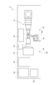
図1は、一実施形態に係るメンテナンス設備の概略構成を示す平面図であり、図2は、一実施形態に係る発電設備の概略構成を示す平面図である。図3は、一実施形態に係る接続された状態のメンテナンス設備及び発電設備を示す図である。図4は、図3に示すメンテナンス設備及び発電設備の概略的な側面図である。なお、図3及び図4において、図1又は図2に示す要素と同一の要素には、図1又は図2における該要素に対応する符号と同一の符号が付されている。
図1は、一実施形態に係るメンテナンス設備の概略構成を示す平面図であり、図2は、一実施形態に係る発電設備の概略構成を示す平面図である。図3は、一実施形態に係る接続された状態のメンテナンス設備及び発電設備を示す図である。図4は、図3に示すメンテナンス設備及び発電設備の概略的な側面図である。なお、図3及び図4において、図1又は図2に示す要素と同一の要素には、図1又は図2における該要素に対応する符号と同一の符号が付されている。
幾つかの実施形態に係るメンテナンス設備は、水上に浮かぶ設備(例えば発電設備)の機器のメンテナンスを行うための設備である。
図1に示すように、一実施形態に係るメンテナンス設備1は、海、湖又は河川等の水上に浮かぶように構成されたメンテナンス用のバージである第1バージ10と、第1バージ10に設けられた第1接続部12と、第1バージ10上に設けられた建屋14と、を備える。また、第1バージ10上において、第1接続部12と建屋14の間に、仮置きスペース20が設けられている。
図1に示すように、一実施形態に係るメンテナンス設備1は、海、湖又は河川等の水上に浮かぶように構成されたメンテナンス用のバージである第1バージ10と、第1バージ10に設けられた第1接続部12と、第1バージ10上に設けられた建屋14と、を備える。また、第1バージ10上において、第1接続部12と建屋14の間に、仮置きスペース20が設けられている。
第1バージ10は、エンジン等の動力を搭載していない典型的な艀であってもよい。この場合、引船や押船等の他の船舶から推進力を与えられて水上を航行するようになっていてもよい。あるいは、第1バージ10は、エンジン等の動力を備えた自走可能なバージであってもよい。
第1接続部12は、メンテナンス対象部を含む機器が搭載された第2バージに第1バージ10を接続するための接続部である。
第1バージ10が接続される上述の第2バージは、後述する発電設備2のバージ(第2バージ40)であってもよく、メンテナンス対象部は、該発電設備に搭載された発電装置のコンポーネントであってもよい。
なお、第1接続部12を介した第1バージ10と第2バージとの接続については後述する。
第1バージ10が接続される上述の第2バージは、後述する発電設備2のバージ(第2バージ40)であってもよく、メンテナンス対象部は、該発電設備に搭載された発電装置のコンポーネントであってもよい。
なお、第1接続部12を介した第1バージ10と第2バージとの接続については後述する。
建屋14は、上述の第2バージから第1バージ10に移されたメンテナンス対象部を一時的に置いておくため、あるいは、メンテナンス対象部をメンテナンス(検査又は部品交換等)するために用いられてもよい。
建屋14は、建屋14の内部空間を形成する壁部16と、壁部16に囲われた内部空間を覆う屋根部(不図示)とを含む。建屋14は、少なくとも、上述のメンテナンス対象部を収容可能な広さを有していてもよい。あるいは、建屋14は、メンテナンス対象部の分解後に該メンテナンス対象部の構成部品を収容可能な広さを有していてもよい。
建屋14の内部には、メンテナンス対象部のメンテナンスに用いられる機器がもうけられていてもよい。例えば、建屋14の内部には、メンテナンス対象部又はメンテナンス対象部の構成部品を吊上げ可能なクレーン18が設けられていてもよい。
クレーン18は、例えば、図1に示すように、建屋14の内部空間の上部に設けられた一対の梁62に支持されるガーダ64上を移動可能なトロリ66に設けられた天井クレーンであってもよい。ガーダ64は、梁62の延在方向に沿って移動可能であってもよい。
クレーン18は、例えば、図1に示すように、建屋14の内部空間の上部に設けられた一対の梁62に支持されるガーダ64上を移動可能なトロリ66に設けられた天井クレーンであってもよい。ガーダ64は、梁62の延在方向に沿って移動可能であってもよい。
仮置きスペース20は、第2バージから第1バージ10に移されたメンテナンス対象部を仮置きするためのスペースであり、第1接続部12と建屋14との間に設けられる。
第1バージ10上には、メンテナンス対象部をメンテナンスするためのユーティリティ機器が設置されていてもよい。ユーティリティ機器は、例えば、空気圧縮機22、発電機24、水タンク26又はポンプ28等を含んでいてもよい。
これらのユーティリティ機器は、図1に示すように、上述の建屋14とは別に設けられる倉庫建屋30の中に設置されていてもよい。あるいは、これらのユーティリティ機器は、上述した建屋14の内部に設置されていてもよい。
これらのユーティリティ機器は、図1に示すように、上述の建屋14とは別に設けられる倉庫建屋30の中に設置されていてもよい。あるいは、これらのユーティリティ機器は、上述した建屋14の内部に設置されていてもよい。
第1バージ10上には、メンテナンス対象部を移送可能な運搬機器32が設けられていてもよい。運搬機器32は、例えば、トレーラ又はフォークリフト等の運搬車両であってもよい。なお、図1に示す運搬機器32はトレーラである。
第1バージ10には、第1バージ10と、該第1バージ10が接続される第2バージとの接触を防止するためのフェンダー70が設けられていてもよい。フェンダー70は、第1接続部12が設けられる側の側面に設けられていてもよく、第1バージ10上に設けられたフェンダー固定具72にロープを介して繋止されていてもよい。フェンダー70は、例えばゴム製であってもよい。
幾つかの実施形態に係る発電設備は、水上で発電を行うための設備であり、発電設備を構成する発電装置のメンテナンス(点検又は部品交換等)を、メンテナンス用バージ上にて実施可能に構成されるものである。
図2に示すように、一実施形態に係る発電設備2は、海、湖又は河川等の水上に浮かぶように構成されたバージである第2バージ40と、第2バージ40上に設けられる発電装置44と、第2バージ40上に設けられたクレーン46と、を備える。
図2に示すように、一実施形態に係る発電設備2は、海、湖又は河川等の水上に浮かぶように構成されたバージである第2バージ40と、第2バージ40上に設けられる発電装置44と、第2バージ40上に設けられたクレーン46と、を備える。
第2バージ40は、エンジン等の動力を搭載していない典型的な艀であってもよい。この場合、引船や押船等の他の船舶から推進力を与えられて水上を航行するようになっていてもよい。あるいは、第2バージ40は、エンジン等の動力を備えた自走可能なバージであってもよい。
第2バージ40には、メンテナンス用の第1バージ(例えば上述のメンテナンス設備1の第1バージ10)に接続するための第2接続部42が設けられている。
第2バージ40に設けられた第2接続部42、及び、上述したメンテナンス設備1の第1バージ10に設けられた第1接続部12は、互いに接続可能に構成されている。第1接続部12と第2接続部42との接続形態は特に限定されず、バージ同士を接続する一般的な接続形態を採用することができる。
幾つかの実施形態では、第1バージ10の第1接続部12(図1参照)は、第1バージ10と第2バージ40とを接続するための係船ロープ15と、係船ロープ15を巻き取るためのウィンチ13と、を含む。係船ロープ15の一端部は、ウィンチ13に固定されている。また、第2バージ40の第2接続部42(図2参照)は、係船ロープ15の他端部を第2バージ40側に固定するためのロープ固定具43を含む。そして、図3及び図4に示すように、係船ロープ15の他端部をロープ固定具43に繋ぐことにより、第1バージ10と第2バージ40とが接続されるようになっている。
なお、図4では、図の簡略化のため、第1バージ10及び第2バージ40上に設置される装置や設備のうち、第1接続部12及び第2接続部42以外のものは図示を省略している。
なお、図4では、図の簡略化のため、第1バージ10及び第2バージ40上に設置される装置や設備のうち、第1接続部12及び第2接続部42以外のものは図示を省略している。
発電装置44は、例えば、ガスタービンや蒸気タービン等のタービン及び発電機を含む発電装置であってもよい。 図2に示す例示的な実施形態において、発電装置44は、ガスタービン及び発電機を含むガスタービン発電装置である。
なお、第2バージ40上には、発電装置44の運転に必要な補機48、発電装置44又は補機48を制御するための制御装置50、又は変圧器52等、発電設備2が機能するために必要な機器が設けられていてもよい。
なお、第2バージ40上には、発電装置44の運転に必要な補機48、発電装置44又は補機48を制御するための制御装置50、又は変圧器52等、発電設備2が機能するために必要な機器が設けられていてもよい。
クレーン46は、第2バージ40において、発電装置44と第2接続部42との間に設けられている。
クレーン46は、発電装置44を構成するタービン(ガスタービン又は蒸気タービン等)の軸方向における側方に位置していてもよい。
クレーン46は、発電装置44を構成するタービン(ガスタービン又は蒸気タービン等)の軸方向における側方に位置していてもよい。
幾つかの実施形態では、発電装置のメンテナンス対象部は、ガスタービン又は蒸気タービンのタービンロータであってもよい。
次に、上述のメンテナンス設備1(図1参照)を用いて上述の発電設備2(図2参照)の発電装置44のメンテナンス対象部をメンテナンスする方法について、説明する。
以下、メンテナンス対象部がガスタービン発電装置のロータ100(図3参照)である場合について説明するが、本発明におけるメンテナンス対象部は、ガスタービンのロータ100に限定されない。
以下、メンテナンス対象部がガスタービン発電装置のロータ100(図3参照)である場合について説明するが、本発明におけるメンテナンス対象部は、ガスタービンのロータ100に限定されない。
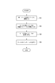
図5は、一実施形態に係るメンテナンス方法のフローチャートである。
幾つかの実施形態に係るメンテナンス方法は、図5に示すように、接続ステップS2と、移動ステップS4と、メンテナンスステップS8と、を備える。幾つかの実施形態では、上述の移動ステップS4の後、かつ、メンテナンスステップS8の前に、運搬ステップS6を行ってもよい。
これらの各ステップについて、以下に説明する。
幾つかの実施形態に係るメンテナンス方法は、図5に示すように、接続ステップS2と、移動ステップS4と、メンテナンスステップS8と、を備える。幾つかの実施形態では、上述の移動ステップS4の後、かつ、メンテナンスステップS8の前に、運搬ステップS6を行ってもよい。
これらの各ステップについて、以下に説明する。
(接続ステップ)
接続ステップS2では、メンテナンス対象部であるロータ100を含むガスタービン発電装置(発電装置44)が設置された発電設備2の第2バージ40(図2参照)にメンテナンス設備1の第1バージ10(図1参照)を接続する。
接続ステップS2では、メンテナンス対象部であるロータ100を含むガスタービン発電装置(発電装置44)が設置された発電設備2の第2バージ40(図2参照)にメンテナンス設備1の第1バージ10(図1参照)を接続する。
幾つかの実施形態では、図3及び図4に示すように、第1バージ10の第1接続部12と、第2バージ40の第2接続部42とを介して、第1バージ10を第2バージ40に接続してもよい。
例えば、第1バージ10上のウィンチ13(第1接続部12)に一端部が固定された係船ロープ15(第1接続部12)の他端部を第2バージ40上のロープ固定具43(第2接続部42)に繋ぐことにより、第1バージ10を第2バージ40に接続してもよい。
一実施形態では、上述のように係船ロープ15の他端部を第2バージ40上のロープ固定具43に繋いだ後、第1バージ10と第2バージ40との間にフェンダー70が配置された状態で、ウィンチ13によって係船ロープ15を巻き取る(即ち係船ロープ15に張力を与える)ようにしてもよい。これにより、第1バージ10と第2バージ40との接触を防止しながら、第1バージ10と第2バージ40を安定的に接続することができる。
例えば、第1バージ10上のウィンチ13(第1接続部12)に一端部が固定された係船ロープ15(第1接続部12)の他端部を第2バージ40上のロープ固定具43(第2接続部42)に繋ぐことにより、第1バージ10を第2バージ40に接続してもよい。
一実施形態では、上述のように係船ロープ15の他端部を第2バージ40上のロープ固定具43に繋いだ後、第1バージ10と第2バージ40との間にフェンダー70が配置された状態で、ウィンチ13によって係船ロープ15を巻き取る(即ち係船ロープ15に張力を与える)ようにしてもよい。これにより、第1バージ10と第2バージ40との接触を防止しながら、第1バージ10と第2バージ40を安定的に接続することができる。
(移動ステップ)
移動ステップS4では、第2バージ40上に設置されたクレーン46で、メンテナンス対象部であるロータ100を第1バージ10の仮置きスペース20に移動させる。
移動ステップS4では、第2バージ40上に設置されたクレーン46で、メンテナンス対象部であるロータ100を第1バージ10の仮置きスペース20に移動させる。
一実施形態に係る移動ステップS4では、発電装置(ガスタービン発電装置)44のロータ100を収容するケーシングを取り外した後、ロータ100をクレーン46で吊り上げる。そして、図3に示すように、第2バージ40に第1バージ10を接続した状態で、吊り上げたロータ100が第1バージ10の仮置きスペース20の上方に位置するまでクレーン46を旋回させ、この位置においてクレーン46でロータ100を吊り下ろし、仮置きスペース20に載置する。
なお、図3において、クレーン46を旋回させてロータ100を移動させている状態が二点鎖線で示されているとともに、第1バージ10の仮置きスペース20に載置されたロータ100が実線で示されている。また、図3において、図の簡略化のため、発電装置44はケーシングが取り外されていない状態のものが示されている。
(運搬ステップ)
運搬ステップS6では、仮置きスペース20に置かれたメンテナンス対象部であるロータ100を、第1バージ10上に設けられた建屋14に運搬機器32を用いて運ぶ。
運搬ステップS6では、仮置きスペース20に置かれたメンテナンス対象部であるロータ100を、第1バージ10上に設けられた建屋14に運搬機器32を用いて運ぶ。
一実施形態では、上述の移動ステップS4においてクレーン46でメンテナンス対象部であるロータ100を移動させる前に、予め、仮置きスペース20内に運搬機器32の荷台部分を配置しておくとともに、クレーン46でロータ100を仮置きスペース20に載置する際、仮置きスペース20内に配置された運搬機器32の荷台部分に載置してもよい。そして、運搬機器32を仮置きスペース20から建屋14に移動させて、ロータ100を建屋14に運搬してもよい。
なお、運搬ステップS6は、必要に応じて実施される任意のステップであり、幾つかの実施形態では、運搬ステップS6は実施されない場合もある。
(メンテナンスステップ)
メンテナンスステップS8では、第1バージ10上でメンテナンス対象部であるロータ100のメンテナンス作業(例えば、点検や部品交換等)を行う。
メンテナンスステップS8は、第1バージ10上の建屋14の中で行ってもよい。
また、メンテナンスステップS8では、第1バージ上のユーティリティ機器(例えば、上述した空気圧縮機22、発電機24、水タンク26又はポンプ28等)を用いて、ロータ100のメンテナンスを行ってもよい。
メンテナンスステップS8では、第1バージ10上でメンテナンス対象部であるロータ100のメンテナンス作業(例えば、点検や部品交換等)を行う。
メンテナンスステップS8は、第1バージ10上の建屋14の中で行ってもよい。
また、メンテナンスステップS8では、第1バージ上のユーティリティ機器(例えば、上述した空気圧縮機22、発電機24、水タンク26又はポンプ28等)を用いて、ロータ100のメンテナンスを行ってもよい。
以上説明したメンテナンス設備1及び発電設備2、又はメンテナンス方法によれば、メンテナンス対象部であるロータ100を含む発電装置44が搭載された第2バージ40に第1バージ10を接続し、第2バージ40上に設置されたクレーン46で、ロータ100を第2バージ40から第1バージ10に移動させて、第1バージ10上にてロータ100のメンテナンスを適切に行うことができる。
また、メンテナンス対象部であるロータ100を含む発電装置44が搭載される第2バージ40と、ロータ100のメンテナンスを行う第1バージ10とが別々に設けられているので、それぞれのバージ(第1バージ10及び第2バージ40)の幅を過度に大きくすることなく、メンテナンス対象部であるロータ100の適切なメンテナンスが可能である。
また、メンテナンス対象部であるロータ100を含む発電装置44が搭載される第2バージ40と、ロータ100のメンテナンスを行う第1バージ10とが別々に設けられているので、それぞれのバージ(第1バージ10及び第2バージ40)の幅を過度に大きくすることなく、メンテナンス対象部であるロータ100の適切なメンテナンスが可能である。
また、第1バージ10と建屋14の間に仮置きスペース20が設けられているので、第2バージ40と、第1バージ10上の建屋14との間で、メンテナンス対象部であるロータ100を円滑に移送できる。さらに、第1バージ10上に、壁部16と屋根部を含む建屋14が設けられているので、該建屋14の内部でメンテナンス対象部であるロータ100のメンテナンスを行うことで、海上におけるロータ100の塩害等を抑制することができる。
また、発電装置44が設けられる第2バージ40上で、発電装置44のメンテナンス対象部であるロータ100と第1バージ10との間にクレーン46が設けられるので、第2バージ40が第1バージ10に接続されたとき、クレーン46は、互いに接続された第1バージ10及び第2バージ40により形成される浮体の重心付近に位置することとなる。よって、該クレーン46によって、第1バージ10と第2バージ40との間でメンテナンス対象部であるロータ100を安定的に移動させることができる。
また、メンテナンス対象部であるロータ100を含む発電装置44が設けられる第2バージ40上にクレーン46を設けたので、第2バージ40上の発電装置44と、クレーン46とはほぼ同じ揺動周期で揺動する。よって、メンテナンス対象部であるロータ100の吊り上げ時又は吊り下げ時に、ロータ100の周囲の部位(例えばケーシング)との接触による損傷が生じにくくなる。
また、メンテナンス対象部であるロータ100を含む発電装置44が設けられる第2バージ40上にクレーン46を設けたので、第2バージ40上の発電装置44と、クレーン46とはほぼ同じ揺動周期で揺動する。よって、メンテナンス対象部であるロータ100の吊り上げ時又は吊り下げ時に、ロータ100の周囲の部位(例えばケーシング)との接触による損傷が生じにくくなる。
また、第1バージ10上のユーティリティ機器を用いることにより、メンテナンス対象部であるロータ100のメンテナンスを適切に行うことができる。
また、運搬機器32によりメンテナンス対象部であるロータ100を第1バージ10上で移送することにより、メンテナンス対象部のメンテナンスを円滑に行うことができる。
以上、本発明の実施形態について説明したが、本発明は上述した実施形態に限定されることはなく、上述した実施形態に変形を加えた形態や、これらの形態を適宜組み合わせた形態も含む。
本明細書において、「ある方向に」、「ある方向に沿って」、「平行」、「直交」、「中心」、「同心」或いは「同軸」等の相対的或いは絶対的な配置を表す表現は、厳密にそのような配置を表すのみならず、公差、若しくは、同じ機能が得られる程度の角度や距離をもって相対的に変位している状態も表すものとする。
例えば、「同一」、「等しい」及び「均質」等の物事が等しい状態であることを表す表現は、厳密に等しい状態を表すのみならず、公差、若しくは、同じ機能が得られる程度の差が存在している状態も表すものとする。
また、本明細書において、四角形状や円筒形状等の形状を表す表現は、幾何学的に厳密な意味での四角形状や円筒形状等の形状を表すのみならず、同じ効果が得られる範囲で、凹凸部や面取り部等を含む形状も表すものとする。
また、本明細書において、一の構成要素を「備える」、「含む」、又は、「有する」という表現は、他の構成要素の存在を除外する排他的な表現ではない。
例えば、「同一」、「等しい」及び「均質」等の物事が等しい状態であることを表す表現は、厳密に等しい状態を表すのみならず、公差、若しくは、同じ機能が得られる程度の差が存在している状態も表すものとする。
また、本明細書において、四角形状や円筒形状等の形状を表す表現は、幾何学的に厳密な意味での四角形状や円筒形状等の形状を表すのみならず、同じ効果が得られる範囲で、凹凸部や面取り部等を含む形状も表すものとする。
また、本明細書において、一の構成要素を「備える」、「含む」、又は、「有する」という表現は、他の構成要素の存在を除外する排他的な表現ではない。
1 メンテナンス設備
2 発電設備
10 第1バージ
12 第1接続部
13 ウィンチ
14 建屋
15 係船ロープ
16 壁部
18 クレーン
20 仮置きスペース
22 空気圧縮機
24 発電機
26 水タンク
28 ポンプ
30 倉庫建屋
32 運搬機器
40 第2バージ
42 第2接続部
43 ロープ固定具
44 発電装置
46 クレーン
48 補機
50 制御装置
52 変圧器
62 梁
64 ガーダ
66 トロリ
70 フェンダー
72 フェンダー固定具
100 ロータ
2 発電設備
10 第1バージ
12 第1接続部
13 ウィンチ
14 建屋
15 係船ロープ
16 壁部
18 クレーン
20 仮置きスペース
22 空気圧縮機
24 発電機
26 水タンク
28 ポンプ
30 倉庫建屋
32 運搬機器
40 第2バージ
42 第2接続部
43 ロープ固定具
44 発電装置
46 クレーン
48 補機
50 制御装置
52 変圧器
62 梁
64 ガーダ
66 トロリ
70 フェンダー
72 フェンダー固定具
100 ロータ
Claims (9)
- 第1バージと、
前記第1バージに設けられ、メンテナンス対象部を含む機器が搭載された第2バージに前記第1バージを接続するための第1接続部と、
前記第1バージ上に設けられ、壁部と屋根部を含む建屋と、
を備え、
前記第1バージ上において、前記第1接続部と前記建屋の間に、前記メンテナンス対象部を置くことが可能な仮置きスペースが設けられた
ことを特徴とするメンテナンス設備。 - 前記第1バージ上に設置されたメンテナンス用のユーティリティ機器をさらに備える
ことを特徴とする請求項1に記載のメンテナンス設備。 - 前記第1バージ上で前記メンテナンス対象部を移送可能な運搬機器をさらに備える
ことを特徴とする請求項1又は2に記載のメンテナンス設備。 - メンテナンス用の第1バージに接続するための第2接続部を含む第2バージと、
前記第2バージ上に設けられる発電装置と、
前記第2バージ上で、前記発電装置のメンテナンス対象部と前記第2接続部との間に設けられたクレーンと、
を備えることを特徴とする発電設備。 - メンテナンス対象部を含む機器が設置された第2バージにメンテナンス用の第1バージを接続するステップと、
前記第2バージ上に設置されたクレーンで、前記メンテナンス対象部を前記第1バージの仮置きスペースに移動させるステップと、
前記第1バージ上で前記メンテナンス対象部をメンテナンスするステップと、
を備えることを特徴とする機器のメンテナンス方法。 - 前記第2バージに前記第1バージを接続した状態で、前記第1バージ上に設けられた壁部と屋根部を含む建屋と、前記第2バージとの間に位置する前記第1バージ上の前記仮置きスペースに前記メンテナンス対象部を移動させる
ことを特徴とする請求項5に記載の機器のメンテナンス方法。 - 前記第2バージに前記第1バージを接続した状態で、前記メンテナンス対象部と前記第1バージとの間にて前記第2バージ上に設けられた前記クレーンにより前記メンテナンス対象部を前記仮置きスペースに移動させる
ことを特徴とする請求項5又は6に記載の機器のメンテナンス方法。 - 前記メンテナンスするステップでは、前記第1バージ上のユーティリティ機器を用いて前記メンテナンス対象部をメンテナンスする
ことを特徴とする請求項5乃至7の何れか一項に記載の機器のメンテナンス方法。 - 前記仮置きスペースに置かれた前記メンテナンス対象部を、前記第1バージ上に設けられた建屋に運搬機器を用いて運ぶステップをさらに備え、
前記メンテナンスするステップでは、前記建屋の中で前記メンテナンス対象部をメンテナンスする
ことを特徴とする請求項5乃至8の何れか一項に記載の機器のメンテナンス方法。
Priority Applications (3)
| Application Number | Priority Date | Filing Date | Title |
|---|---|---|---|
| KR1020197017120A KR102221288B1 (ko) | 2017-03-31 | 2018-03-22 | 메인터넌스 설비 및 발전 설비 그리고 기기의 메인터넌스 방법 |
| CN201880005230.3A CN110087988A (zh) | 2017-03-31 | 2018-03-22 | 维护设备及发电设备以及机器的维护方法 |
| US16/465,270 US11208179B2 (en) | 2017-03-31 | 2018-03-22 | Maintenance facility, power generation facility, and maintenance method for device |
Applications Claiming Priority (2)
| Application Number | Priority Date | Filing Date | Title |
|---|---|---|---|
| JP2017072106A JP7033854B2 (ja) | 2017-03-31 | 2017-03-31 | メンテナンス設備及び発電設備並びに機器のメンテナンス方法 |
| JP2017-072106 | 2017-03-31 |
Publications (1)
| Publication Number | Publication Date |
|---|---|
| WO2018180935A1 true WO2018180935A1 (ja) | 2018-10-04 |
Family
ID=63675808
Family Applications (1)
| Application Number | Title | Priority Date | Filing Date |
|---|---|---|---|
| PCT/JP2018/011542 Ceased WO2018180935A1 (ja) | 2017-03-31 | 2018-03-22 | メンテナンス設備及び発電設備並びに機器のメンテナンス方法 |
Country Status (5)
| Country | Link |
|---|---|
| US (1) | US11208179B2 (ja) |
| JP (1) | JP7033854B2 (ja) |
| KR (1) | KR102221288B1 (ja) |
| CN (1) | CN110087988A (ja) |
| WO (1) | WO2018180935A1 (ja) |
Families Citing this family (1)
| Publication number | Priority date | Publication date | Assignee | Title |
|---|---|---|---|---|
| JP7033854B2 (ja) * | 2017-03-31 | 2022-03-11 | 三菱重工業株式会社 | メンテナンス設備及び発電設備並びに機器のメンテナンス方法 |
Citations (4)
| Publication number | Priority date | Publication date | Assignee | Title |
|---|---|---|---|---|
| JPS6040389U (ja) * | 1983-08-24 | 1985-03-20 | 日立造船株式会社 | 半潜水式作業台 |
| JP2010168217A (ja) * | 2008-12-12 | 2010-08-05 | Nuovo Pignone Spa | 重量機器の移動及び位置合わせ方法 |
| JP2010175262A (ja) * | 2009-01-27 | 2010-08-12 | Koichiro Mori | 海上移動式原子力発電プラント |
| US20140366792A1 (en) * | 2011-05-27 | 2014-12-18 | Amy Louise LINKE | Mobile barge and method of operation of mobile barge |
Family Cites Families (21)
| Publication number | Priority date | Publication date | Assignee | Title |
|---|---|---|---|---|
| US4281615A (en) * | 1977-10-31 | 1981-08-04 | Sedco, Inc. | Self-propelled semi-submersible service vessel |
| JPS5835914B2 (ja) * | 1977-12-06 | 1983-08-05 | 日立造船株式会社 | 原子力船用サ−ビス基地 |
| JPS55165890A (en) * | 1979-06-07 | 1980-12-24 | Mitsubishi Heavy Ind Ltd | Working boat |
| JPS59115806A (ja) | 1982-12-24 | 1984-07-04 | 塩谷 雅雄 | 半球ド−ム型コンクリ−トブロツク成型時におけるコンクリ−ト投入方法 |
| JPS59115806U (ja) | 1983-01-26 | 1984-08-04 | 株式会社日立製作所 | 超コンパクトコンバインドプラント |
| JPS6040389A (ja) | 1983-08-15 | 1985-03-02 | 株式会社日立製作所 | エレベ−タ−乗かごの照明装置 |
| JPH0171105U (ja) | 1987-10-30 | 1989-05-12 | ||
| US5558037A (en) * | 1995-03-15 | 1996-09-24 | Manning; Foster T. | Semisubmersible vessel with forward-mounted crane |
| WO2007009464A1 (en) * | 2005-07-19 | 2007-01-25 | Pp Energy Aps | Plant for exploiting wind energy at sea |
| CN101885371A (zh) * | 2010-03-15 | 2010-11-17 | 陈元文 | 一种移动式挤出设备专用驳船 |
| JP5736133B2 (ja) * | 2010-07-23 | 2015-06-17 | ジャパンマリンユナイテッド株式会社 | 浮体構造物作業システム、作業船及び浮体構造物作業方法 |
| DE102012007613A1 (de) * | 2012-04-16 | 2013-10-17 | Walter Schopf | Schwimmende Trägerbasis für Offshore-Windenergieanlagen |
| CN103032276A (zh) * | 2012-11-30 | 2013-04-10 | 广东明阳风电产业集团有限公司 | 海上风机导管架基础平台上电气设备布置及维护方案 |
| JP2014148261A (ja) * | 2013-02-01 | 2014-08-21 | Mitsubishi Heavy Ind Ltd | 作業台船の固定方法、保守方法、設置方法、浮体及び浮体式風力設備 |
| CN103112553B (zh) | 2013-02-04 | 2015-11-25 | 大连海事大学 | 自航式半潜维修船及使用方法 |
| US20140261128A1 (en) * | 2013-03-15 | 2014-09-18 | Waller Marine, Inc. | Barge Mounted Floating Power Plant |
| JP5480991B1 (ja) * | 2013-04-02 | 2014-04-23 | 美津濃株式会社 | 蛍光増白高架橋ポリアクリレート系繊維とその製造方法及びこれを含む繊維構造物 |
| EP2989000B1 (en) * | 2013-04-25 | 2019-10-16 | Keppel Offshore & Marine Technology Centre Pte Ltd | A system and method for dynamically positioning a floating vessel alongside a turret moored floating vessel |
| US9567044B2 (en) * | 2013-12-13 | 2017-02-14 | Jurong Shipyard Pte. Ltd. | Semisubmersible with tunnel structure |
| KR200479575Y1 (ko) * | 2014-03-27 | 2016-02-15 | 대우조선해양 주식회사 | 부유식 발전 플랜트 및 그 부유식 발전 플랜트의 오버헤드 크레인 배치구조 |
| JP7033854B2 (ja) * | 2017-03-31 | 2022-03-11 | 三菱重工業株式会社 | メンテナンス設備及び発電設備並びに機器のメンテナンス方法 |
-
2017
- 2017-03-31 JP JP2017072106A patent/JP7033854B2/ja not_active Expired - Fee Related
-
2018
- 2018-03-22 CN CN201880005230.3A patent/CN110087988A/zh active Pending
- 2018-03-22 US US16/465,270 patent/US11208179B2/en not_active Expired - Fee Related
- 2018-03-22 WO PCT/JP2018/011542 patent/WO2018180935A1/ja not_active Ceased
- 2018-03-22 KR KR1020197017120A patent/KR102221288B1/ko not_active Expired - Fee Related
Patent Citations (4)
| Publication number | Priority date | Publication date | Assignee | Title |
|---|---|---|---|---|
| JPS6040389U (ja) * | 1983-08-24 | 1985-03-20 | 日立造船株式会社 | 半潜水式作業台 |
| JP2010168217A (ja) * | 2008-12-12 | 2010-08-05 | Nuovo Pignone Spa | 重量機器の移動及び位置合わせ方法 |
| JP2010175262A (ja) * | 2009-01-27 | 2010-08-12 | Koichiro Mori | 海上移動式原子力発電プラント |
| US20140366792A1 (en) * | 2011-05-27 | 2014-12-18 | Amy Louise LINKE | Mobile barge and method of operation of mobile barge |
Also Published As
| Publication number | Publication date |
|---|---|
| US11208179B2 (en) | 2021-12-28 |
| US20190291829A1 (en) | 2019-09-26 |
| JP7033854B2 (ja) | 2022-03-11 |
| CN110087988A (zh) | 2019-08-02 |
| JP2018172070A (ja) | 2018-11-08 |
| KR20190082909A (ko) | 2019-07-10 |
| KR102221288B1 (ko) | 2021-02-26 |
Similar Documents
| Publication | Publication Date | Title |
|---|---|---|
| CN104136358B (zh) | 用于在运输与装配过程中搬运风轮机部件的方法及设备 | |
| CN105980699B (zh) | 用于储存并且/或者运输多个对象的方法 | |
| JP5820953B1 (ja) | 風力発電装置の組み付け方法、風力発電装置の分解方法、風力発電装置の設置方法、及び風力発電装置の作業用船舶 | |
| KR102401161B1 (ko) | 선박과 해양 설비 사이에서 적재물을 고정 및 이송하기 위한 방법 및 이를 위한 장치 | |
| US12276253B2 (en) | Assembling and installing a wind turbine | |
| CN103670946B (zh) | 安装离岸风力涡轮机的方法及其运输船 | |
| CN103112553A (zh) | 自航式半潜维修船 | |
| CN103939300B (zh) | 一种海上风电整机安装方法 | |
| KR20120033854A (ko) | 풍력 발전기 설치용 선박 | |
| KR101281644B1 (ko) | 선체블록의 해상운송용 고박 방법 및 장치 | |
| CN101792012B (zh) | 一种海上风机整体运输与安装的方法及专用工程船 | |
| CN111188324A (zh) | 一种海上风电安装平台升降系统水上合拢工艺 | |
| JP2012107585A (ja) | 洋上風車設置用船舶およびこれを用いた洋上風車設置方法 | |
| JP2012112370A (ja) | 洋上風車設置用船舶およびこれを用いた洋上風車設置方法 | |
| WO2018180935A1 (ja) | メンテナンス設備及び発電設備並びに機器のメンテナンス方法 | |
| JP2023537311A (ja) | 風力タービンタワーを輸送するためのシステム及び方法 | |
| CN112119006B (zh) | 海上作业设施及其建造方法 | |
| KR20090022045A (ko) | 대형블럭의 플로팅도크 탑재방법 및 이를 이용한해상건조공법 | |
| KR20120112750A (ko) | 바지선에 의한 해상 수송 방법 및 해상 수송용 바지선 | |
| KR102730108B1 (ko) | 부유식 지그 및 이를 이용한 해상풍력발전기용 지지구조물 설치 방법 | |
| KR20130022924A (ko) | 엔진 룸에서 발전기를 제거하는 방법 및 시스템 | |
| CN119329693B (zh) | 一种风电设备安装运输船船型及总布置 | |
| NL2034644B1 (en) | A method and system for installing a wind turbine offshore and an assembly for use in combination with said method and system | |
| KR20250155585A (ko) | 해상 풍력 터빈용 플로트 대량 생산 방법 | |
| GB2564152A (en) | Offshore decommissioning vessel and methods of use |
Legal Events
| Date | Code | Title | Description |
|---|---|---|---|
| 121 | Ep: the epo has been informed by wipo that ep was designated in this application |
Ref document number: 18776929 Country of ref document: EP Kind code of ref document: A1 |
|
| ENP | Entry into the national phase |
Ref document number: 20197017120 Country of ref document: KR Kind code of ref document: A |
|
| NENP | Non-entry into the national phase |
Ref country code: DE |
|
| 122 | Ep: pct application non-entry in european phase |
Ref document number: 18776929 Country of ref document: EP Kind code of ref document: A1 |