WO2018179784A1 - Système de communication - Google Patents
Système de communication Download PDFInfo
- Publication number
- WO2018179784A1 WO2018179784A1 PCT/JP2018/002747 JP2018002747W WO2018179784A1 WO 2018179784 A1 WO2018179784 A1 WO 2018179784A1 JP 2018002747 W JP2018002747 W JP 2018002747W WO 2018179784 A1 WO2018179784 A1 WO 2018179784A1
- Authority
- WO
- WIPO (PCT)
- Prior art keywords
- terminal
- light
- cradle
- infrared
- infrared light
- Prior art date
Links
- 238000004891 communication Methods 0.000 title claims abstract description 34
- 238000001514 detection method Methods 0.000 claims abstract description 30
- 230000015654 memory Effects 0.000 claims description 50
- 230000004044 response Effects 0.000 claims description 11
- 230000005540 biological transmission Effects 0.000 description 31
- 238000010586 diagram Methods 0.000 description 21
- 230000007704 transition Effects 0.000 description 17
- 238000012545 processing Methods 0.000 description 7
- 238000000034 method Methods 0.000 description 4
- 230000000694 effects Effects 0.000 description 3
- 230000010365 information processing Effects 0.000 description 3
- 239000000463 material Substances 0.000 description 3
- XEEYBQQBJWHFJM-UHFFFAOYSA-N Iron Chemical compound [Fe] XEEYBQQBJWHFJM-UHFFFAOYSA-N 0.000 description 2
- 238000007792 addition Methods 0.000 description 2
- 238000013459 approach Methods 0.000 description 2
- 238000005516 engineering process Methods 0.000 description 2
- 230000004308 accommodation Effects 0.000 description 1
- 229910052742 iron Inorganic materials 0.000 description 1
- 230000005389 magnetism Effects 0.000 description 1
- 238000012986 modification Methods 0.000 description 1
- 230000004048 modification Effects 0.000 description 1
- 238000012544 monitoring process Methods 0.000 description 1
- 239000011347 resin Substances 0.000 description 1
- 229920005989 resin Polymers 0.000 description 1
Images


Classifications
-
- H—ELECTRICITY
- H04—ELECTRIC COMMUNICATION TECHNIQUE
- H04B—TRANSMISSION
- H04B10/00—Transmission systems employing electromagnetic waves other than radio-waves, e.g. infrared, visible or ultraviolet light, or employing corpuscular radiation, e.g. quantum communication
-
- G—PHYSICS
- G08—SIGNALLING
- G08C—TRANSMISSION SYSTEMS FOR MEASURED VALUES, CONTROL OR SIMILAR SIGNALS
- G08C23/00—Non-electrical signal transmission systems, e.g. optical systems
- G08C23/04—Non-electrical signal transmission systems, e.g. optical systems using light waves, e.g. infrared
-
- B—PERFORMING OPERATIONS; TRANSPORTING
- B64—AIRCRAFT; AVIATION; COSMONAUTICS
- B64D—EQUIPMENT FOR FITTING IN OR TO AIRCRAFT; FLIGHT SUITS; PARACHUTES; ARRANGEMENTS OR MOUNTING OF POWER PLANTS OR PROPULSION TRANSMISSIONS IN AIRCRAFT
- B64D11/00—Passenger or crew accommodation; Flight-deck installations not otherwise provided for
- B64D11/0015—Arrangements for entertainment or communications, e.g. radio, television
- B64D11/00151—Permanently mounted seat back monitors
-
- B—PERFORMING OPERATIONS; TRANSPORTING
- B64—AIRCRAFT; AVIATION; COSMONAUTICS
- B64D—EQUIPMENT FOR FITTING IN OR TO AIRCRAFT; FLIGHT SUITS; PARACHUTES; ARRANGEMENTS OR MOUNTING OF POWER PLANTS OR PROPULSION TRANSMISSIONS IN AIRCRAFT
- B64D11/00—Passenger or crew accommodation; Flight-deck installations not otherwise provided for
- B64D11/0015—Arrangements for entertainment or communications, e.g. radio, television
- B64D11/00155—Individual entertainment or communication system remote controls therefor, located in or connected to seat components, e.g. to seat back or arm rest
-
- G—PHYSICS
- G08—SIGNALLING
- G08C—TRANSMISSION SYSTEMS FOR MEASURED VALUES, CONTROL OR SIMILAR SIGNALS
- G08C17/00—Arrangements for transmitting signals characterised by the use of a wireless electrical link
- G08C17/02—Arrangements for transmitting signals characterised by the use of a wireless electrical link using a radio link
-
- H—ELECTRICITY
- H04—ELECTRIC COMMUNICATION TECHNIQUE
- H04N—PICTORIAL COMMUNICATION, e.g. TELEVISION
- H04N21/00—Selective content distribution, e.g. interactive television or video on demand [VOD]
- H04N21/20—Servers specifically adapted for the distribution of content, e.g. VOD servers; Operations thereof
- H04N21/21—Server components or server architectures
- H04N21/214—Specialised server platform, e.g. server located in an airplane, hotel, hospital
- H04N21/2146—Specialised server platform, e.g. server located in an airplane, hotel, hospital located in mass transportation means, e.g. aircraft, train or bus
-
- H—ELECTRICITY
- H04—ELECTRIC COMMUNICATION TECHNIQUE
- H04N—PICTORIAL COMMUNICATION, e.g. TELEVISION
- H04N21/00—Selective content distribution, e.g. interactive television or video on demand [VOD]
- H04N21/40—Client devices specifically adapted for the reception of or interaction with content, e.g. set-top-box [STB]; Operations thereof
- H04N21/41—Structure of client; Structure of client peripherals
- H04N21/422—Input-only peripherals, i.e. input devices connected to specially adapted client devices, e.g. global positioning system [GPS]
- H04N21/42204—User interfaces specially adapted for controlling a client device through a remote control device; Remote control devices therefor
- H04N21/42206—User interfaces specially adapted for controlling a client device through a remote control device; Remote control devices therefor characterized by hardware details
- H04N21/42221—Transmission circuitry, e.g. infrared [IR] or radio frequency [RF]
-
- H—ELECTRICITY
- H04—ELECTRIC COMMUNICATION TECHNIQUE
- H04Q—SELECTING
- H04Q9/00—Arrangements in telecontrol or telemetry systems for selectively calling a substation from a main station, in which substation desired apparatus is selected for applying a control signal thereto or for obtaining measured values therefrom
-
- G—PHYSICS
- G08—SIGNALLING
- G08C—TRANSMISSION SYSTEMS FOR MEASURED VALUES, CONTROL OR SIMILAR SIGNALS
- G08C2201/00—Transmission systems of control signals via wireless link
- G08C2201/10—Power supply of remote control devices
- G08C2201/12—Power saving techniques of remote control or controlled devices
-
- G—PHYSICS
- G08—SIGNALLING
- G08C—TRANSMISSION SYSTEMS FOR MEASURED VALUES, CONTROL OR SIMILAR SIGNALS
- G08C2201/00—Transmission systems of control signals via wireless link
- G08C2201/20—Binding and programming of remote control devices
-
- G—PHYSICS
- G08—SIGNALLING
- G08C—TRANSMISSION SYSTEMS FOR MEASURED VALUES, CONTROL OR SIMILAR SIGNALS
- G08C2201/00—Transmission systems of control signals via wireless link
- G08C2201/70—Device selection
- G08C2201/71—Directional beams
-
- H—ELECTRICITY
- H04—ELECTRIC COMMUNICATION TECHNIQUE
- H04Q—SELECTING
- H04Q2209/00—Arrangements in telecontrol or telemetry systems
- H04Q2209/80—Arrangements in the sub-station, i.e. sensing device
- H04Q2209/88—Providing power supply at the sub-station
- H04Q2209/883—Providing power supply at the sub-station where the sensing device enters an active or inactive mode
Definitions
- the present disclosure relates to a communication system that performs wireless communication by performing pairing between two devices.
- Japanese Patent Laid-Open No. 2004-26883 instructs an operation-side first communication unit capable of transmitting a signal to an operation target device, an operation-side second communication unit capable of transmitting / receiving a signal to / from the operation target device, and an operation target device to start pairing.
- a remote control device including a pairing start unit that transmits a pairing start signal via the operation side first communication unit and an operation side pairing execution unit that performs pairing via the operation side second communication unit. To do. With this configuration, pairing can be easily performed without placing a burden on the user.
- This disclosure provides a communication system that can be easily paired.
- the communication system includes a first terminal and a second terminal that includes a storage unit that can store the first terminal and performs wireless communication with the first terminal.
- the first terminal includes a first light emitting unit that emits infrared light, a first light receiving unit that receives infrared light, a first memory that stores first identification information for identifying the first terminal, 1 controller.
- the first controller determines that the signal obtained by demodulating the infrared light received by the first light receiving unit includes a pairing request signal, the first controller causes the first light emitting unit to emit light based on the first specific information.
- the second terminal includes a second storage sensor that detects that the first terminal is stored in the storage unit, a second light emitting unit that emits infrared light, a second light receiving unit that receives infrared light, Two memories and a second controller.
- the second controller emits the second light-emitting unit based on the pairing request signal and demodulates the infrared light received by the second light-receiving unit in response to the second storage sensor detecting the storage of the first terminal.
- the first specific information is stored in the second memory, and when it is determined that the information obtained by demodulating the infrared light received by the second light receiving unit includes the first specific information stored in the second memory Take control.
- the communication system includes a first terminal, and a second terminal that performs wireless communication with the first terminal and can be engaged with the first terminal.
- the first terminal includes a first light emitting unit that emits infrared light, a first light receiving unit that receives infrared light, a first memory that stores first identification information for identifying the first terminal, 1 controller.
- the first controller determines that the signal obtained by demodulating the infrared light received by the first light receiving unit includes a pairing request signal, the first controller causes the first light emitting unit to emit light based on the first specific information.
- the second terminal includes a second engagement sensor that detects engagement with the first terminal, a second light emitting unit that emits infrared light, a second light receiving unit that receives infrared light, and a second memory. And a second controller.
- the second controller emits the second light-emitting unit based on the pairing request signal and demodulates the infrared light received by the second light-receiving unit in response to the second storage sensor detecting the storage of the first terminal.
- the first specific information is stored in the second memory, and when it is determined that the information obtained by demodulating the infrared light received by the second light receiving unit includes the first specific information stored in the second memory Take control.
- the communication system according to the present disclosure is effective for easy pairing.
- FIG. 3 is a block diagram showing the configuration of the in-flight monitor system in the first embodiment.
- FIG. 2 is a block diagram showing an electrical configuration of an in-flight monitor according to the first embodiment.
- FIG. 3 is a block diagram showing an electrical configuration of the cradle in the first embodiment.
- FIG. 3 is a block diagram showing an electrical configuration of a remote control according to the first embodiment.
- FIG. 9 is a block diagram showing an electrical configuration of a remote control according to the second embodiment. Sequence diagram for explaining pairing and operations after pairing in the in-flight monitor system in the second embodiment The figure which shows the positional relationship of each part of the cradle and remote control in Embodiment 3.
- FIG. 9 is a block diagram showing an electrical configuration of a remote control according to the third embodiment.
- FIG. 1 is a diagram showing an arrangement of an in-flight monitor system 1 provided in an aircraft in the first embodiment.
- a plurality of seats 500 for seating passengers (users) are provided.
- An in-flight monitor 200 and a cradle 300 are provided at predetermined positions on the back side of the back of the seat 500.
- Each of the in-flight monitors 200 has the same configuration.
- Each of the cradle 300 has the same configuration.
- the cradle 300 includes a storage unit 311.
- the cradle 300 can store the remote control 400 in the storage unit 311.
- Each of the remote controllers 400 has the same configuration.
- the in-flight monitor 200 and the cradle 300 are visible to the passenger at a position facing the passenger sitting on the seat 500 behind the seat 500 on which the in-flight monitor 200 and the cradle 300 are mounted. Installed.
- the passenger operates the touch panel (described later) or the remote control 400 of the in-flight monitor 200 provided in the front seat 500 while sitting on the seat 500, and also watches the video displayed on the in-flight monitor 200. It is possible to receive various in-flight services.
- the passenger can operate the remote controller 400 in a state where the remote controller 400 is stored in the cradle 300 or in a state where the remote controller 400 is removed from the cradle 300.
- An aircraft is an example of transportation equipment.
- the remote control is an example of a first terminal.
- the cradle is an example of the second terminal.
- FIG. 2 is a block diagram showing the configuration of the in-flight monitor system 1.
- the in-flight monitor system 1 includes an in-flight monitor 200, a cradle 300, and a remote controller 400.
- the in-flight monitor 200 can reproduce the content distributed from the server device.
- the in-flight monitor 200 is wired to the cradle 300, and can communicate with the cradle 300 by wire.
- the cradle 300 can wirelessly communicate with the remote control 400 using an infrared signal. That is, the in-flight monitor 200 can receive the operation content from the remote controller 400 via the cradle 300 and can perform processing corresponding to the received operation content.
- the in-flight monitor system is an example of a communication system.
- FIG. 3 is a diagram showing the positional relationship between the cradle 300 and the remote controller 400.
- FIG. 3 shows a state in which the remote controller 400 is stored in the storage unit 311 of the cradle 300.
- the cradle 300 includes a magnetic sensor 304, an infrared receiver 305, and an infrared transmitter 306.
- the cradle 300 includes a storage unit 311 for storing the remote control 400 and an IR (InfraRed) window 313.
- the storage unit 311 has a concave shape capable of holding the remote control 400 and includes a bottom surface 312 and a side surface 315.
- the magnetic sensor 304 is disposed inside the bottom surface 312.
- the IR window 313 is provided on the side surface 315.
- the IR window 313 is formed of a material that transmits infrared rays.
- the infrared receiving unit 305 is disposed inside the IR window 313 and can receive infrared signals from the outside through the IR window 313.
- the infrared transmission unit 306 is disposed inside the IR window 313 and can transmit infrared signals to the outside through the IR window 313.
- the infrared receiving unit 305 is an example of a second light receiving unit.
- the infrared transmission unit 306 is an example of a second light emitting unit.
- the remote control 400 includes an infrared receiver 405, an infrared transmitter 406, a magnet 409, an operation unit 411, and an IR window 413.
- Magnet 409 is arranged inside bottom surface 412 of remote controller 400.
- the operation unit 411 is an input interface such as a push button or a touch panel, and is provided on the upper surface 414 of the remote control 400.
- IR window 413 is provided on side surface 415 of remote controller 400.
- the IR window 413 is formed of a material that transmits infrared rays.
- the infrared receiving unit 405 is disposed inside the IR window 413 and can receive infrared signals from the outside through the IR window 413.
- the infrared transmitter 406 is disposed inside the IR window 413 and can transmit infrared signals to the outside through the IR window 413.
- the infrared receiving unit 405 is an example of a first light receiving unit.
- the infrared transmission unit 406 is an example of a first light emitting unit.
- the magnet 409 is an example of a magnetized magnetic body.
- the bottom surface 312 of the cradle 300 and the bottom surface 412 of the remote control 400 face each other.
- the magnetic sensor 304 of the cradle 300 and the magnet 409 of the remote control 400 face each other with the bottom surface 312 of the cradle and the bottom surface 412 of the remote control 400 interposed therebetween.
- the bottom surface 312 of the cradle and the bottom surface 412 of the remote controller 400 are each formed of a nonmagnetic material such as resin. Therefore, the magnetic sensor 304 can detect the magnetic field generated by the magnet 409 in a state where the remote control 400 is housed in the cradle 300.
- the IR window 313 of the cradle 300 and the IR window 413 of the remote control 400 face each other.
- the infrared reception unit 305 of the cradle 300 and the infrared transmission unit 406 of the remote control 400 face each other with the IR window 313 of the cradle 300 and the IR window 413 of the remote control 400 interposed therebetween.
- the infrared receiver 305 can receive the infrared signal transmitted by the infrared transmitter 406.
- the infrared transmission unit 306 of the cradle 300 and the infrared reception unit 405 of the remote control 400 face each other with the IR window 313 of the cradle 300 and the IR window 413 of the remote control 400 interposed therebetween.
- the infrared receiver 405 can receive the infrared signal transmitted by the infrared transmitter 306.
- FIG. 4 is a block diagram showing an electrical configuration of the in-flight monitor 200.
- the in-flight monitor 200 includes a network interface (I / F) 201, a CPU 202, a memory 203, a touch panel 204, a display 206, and a USB interface (I / F) 207.
- the network interface 201 is an interface for the CPU 202 to communicate with an external device (not shown) such as a server device via a network cable.
- the CPU 202 executes a program stored in the memory 203 and performs various calculations and information processing.
- the CPU 202 can read from and write to the memory 203. Further, the CPU 202 communicates with the server device via the network interface 201. Further, the CPU 202 communicates with the cradle 300 via the USB interface 207.
- the memory 203 stores a program executed by the CPU 202 and a calculation result of the CPU 202.
- the memory 203 is configured by a flash memory or a RAM.
- the touch panel 204 is disposed on the surface of the display 206.
- information indicating the position touched by the touch panel 204 is transmitted to the CPU 202.
- the CPU 202 performs control according to this information, the passenger can perform an intuitive operation.
- the display 206 displays various contents in accordance with instructions from the CPU 202.
- the USB interface 207 is an interface for the CPU 202 to communicate with the cradle 300 via a communication cable.
- FIG. 5 is a block diagram showing an electrical configuration of the cradle 300.
- the cradle 300 includes a CPU 302, a memory 303, a magnetic sensor 304, an infrared receiving unit 305, an infrared transmitting unit 306, and a USB interface (I / F) 307.
- the CPU 302 executes a program stored in the memory 303 to perform various calculations and information processing.
- the CPU 302 can read from and write to the memory 303.
- the CPU 302 communicates with the in-flight monitor 200 via the USB interface 307.
- the CPU 302 causes the infrared transmission unit 306 to emit light based on the signal to be transmitted. More specifically, the CPU 302 modulates a signal to be transmitted and causes the infrared transmitter 306 to emit light according to the modulated signal.
- the CPU 302 is an example of a second controller.
- the memory 303 stores a program executed by the CPU 302, a calculation result of the CPU 302, and an ID of the remote controller 400.
- the ID of the remote controller 400 is information for specifying one remote controller 400 from among the plurality of remote controllers 400.
- the ID of the remote control is an example of first specific information.
- the memory 303 is configured by a flash memory or a RAM.
- the memory 303 is an example of a second memory.
- the magnetic sensor 304 detects the magnetic field at the position where the magnetic sensor 304 is placed. When the magnetic field exceeds a certain threshold value, the magnetic sensor 304 transmits a detection signal indicating that the threshold value has been exceeded to the CPU 302.
- the magnetic sensor 304 detects the magnetic field of the magnet 409 provided in the remote controller 400 and transmits a detection signal. That is, when the remote controller 400 is housed in the cradle 300, the magnetic sensor 304 transmits a detection signal.
- the magnetic sensor 304 is an example of a second storage sensor.
- the infrared receiving unit 305 includes a light receiving element 305a and a demodulation circuit 305b.
- the light receiving element 305a receives an infrared signal from the remote controller 400.
- the demodulation circuit 305b demodulates the received signal from the infrared signal and transmits it to the CPU 302.
- the infrared transmission unit 306 is an LED that emits infrared light.
- the infrared transmission unit 306 emits an infrared signal based on the signal modulated by the CPU 302.
- the USB interface 307 is an interface for the CPU 302 to communicate with the in-flight monitor 200 via a communication cable.
- FIG. 6 is a block diagram showing an electrical configuration of the remote control 400.
- the remote control 400 includes a CPU 402, a memory 403, an infrared receiver 405, an infrared transmitter 406, and an operation unit 411.
- the CPU 402 executes programs stored in the memory 403 and performs various calculations and information processing.
- the CPU 402 can read from and write to the memory 403.
- the CPU 402 causes the infrared transmission unit 406 to emit light based on the signal to be transmitted. More specifically, the CPU 402 modulates a signal to be transmitted and causes the infrared transmission unit 406 to emit light according to the modulated signal.
- the CPU 402 is an example of a first controller.
- the memory 403 stores a program executed by the CPU 402, a calculation result of the CPU 402, and an ID of the remote controller 400.
- the memory 403 is configured by a flash memory or a RAM.
- the memory 403 is an example of a first memory.
- the infrared receiving unit 405 includes a light receiving element 405a and a demodulation circuit 405b.
- the light receiving element 405a receives the infrared signal from the cradle 300.
- the demodulation circuit 405b demodulates the received signal from the infrared signal and transmits it to the CPU 402.
- the infrared transmission unit 406 is an LED (light emitting element) that emits infrared light.
- the infrared transmission unit 406 emits an infrared signal based on the signal modulated by the CPU 402.
- the operation unit 411 is an input interface such as a push button or a touch panel. When the passenger operates the operation unit 411, a signal corresponding to the operation is transmitted to the CPU 402.
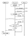
- FIG. 7 is a sequence diagram for explaining the pairing and the operation after pairing in the in-flight monitor system 1.
- the cradle 300 When a passenger or a passenger stores the remote control 400 in the storage unit 311 of the cradle 300, the cradle 300 performs pairing with the stored remote control 400. Once pairing is performed, the cradle 300 thereafter transmits a reception signal from the paired remote control 400 to the in-flight monitor 200, while ignoring reception signals from other than the paired remote control 400.
- the operation of the in-flight monitor system 1 will be described with reference to FIG.
- the pairing operation between the cradle 300 and the remote controller 400 will be described.
- the CPU 302 of the cradle 300 monitors the storage of the remote control 400. Specifically, the CPU 302 stands by until a detection signal is received from the magnetic sensor 304.
- the magnetic sensor 304 provided in the cradle 300 and the magnet 409 provided in the remote control 400 approach each other. Then, the magnetic sensor 304 detects the magnetic field of the magnet 409 and outputs a detection signal.
- CPU302 detects accommodation of remote control 400 (S701).
- the CPU 302 of the cradle 300 receives the detection signal, it determines that the remote control 400 is stored.
- the CPU 302 transmits a pairing request signal to the remote controller 400 using the infrared transmission unit 306 (S702).
- the pairing request signal is a signal including information indicating that the cradle 300 requests the remote controller 400 to perform a pairing operation.
- the CPU 402 of the remote control 400 monitors the pairing request signal from the cradle 300 by the infrared receiving unit 405.
- the CPU 402 transmits its own ID (ID of the remote controller 400) to the cradle 300 using the infrared transmission unit 406 (S703).
- the CPU 302 of the cradle 300 receives the ID of the remote controller 400 by the infrared receiving unit 305 and stores it in the memory 303 (S705).
- the cradle 300 transmits a processing completion notification to the remote control 400 using the infrared transmission unit 306 (S707). With the above operation, the pairing operation is completed.
- the remote control 400 may be stored in the cradle 300, or the passenger takes out the remote control 400 from the cradle 300, and the IR window 413 (infrared transmission unit 406) of the remote control 400 is placed in the IR of the cradle 300. It may be in a state of being held toward the window 313 (infrared receiving unit 305), that is, in a state where infrared communication is possible with each other.
- the CPU 402 of the remote control 400 transmits operation information using the infrared transmission unit 406 (S711).
- the operation information includes the ID of the remote controller 400 and the operation content (for example, information indicating that the enter button has been pressed).
- operation information including the ID of the remote control 400 and the operation content indicating which button is pressed is transmitted using the infrared transmission unit 406. ,Send.
- the CPU 302 of the cradle 300 monitors reception of operation information from the remote control 400 by the infrared receiving unit 305.
- the CPU 302 compares the ID of the remote control 400 included in the operation information with the ID of the remote control 400 stored in the memory 303 (S712).
- the cradle 300 determines that the received operation information is transmitted from the paired remote control 400.
- the CPU 302 performs control according to the operation information. Specifically, the CPU 302 transmits the operation content included in the operation information to the in-flight monitor 200 using the USB interface 307 (S713).
- the CPU 202 of the in-flight monitor 200 performs processing corresponding to the operation content (S714). If the IDs are different as a result of the comparison (No in S712), the cradle 300 determines that the received operation information is not transmitted from the paired remote control 400, and ignores the operation information.
- the in-flight monitor 200 can perform various operations corresponding to only the operation of the remote controller 400 paired with the connected cradle 300.
- in-flight monitor system 1 performs infrared communication between remote controller 400 and cradle 300 including storage unit 311 in which remote controller 400 can be stored.
- the remote control 400 includes an infrared transmission unit 406 that emits infrared light, an infrared reception unit 405 that receives infrared light, a memory 403 that stores an ID of the remote control 400 for identifying the remote control 400, and an infrared reception unit 405.
- a CPU 402 that causes the infrared transmitter 406 to emit light based on the ID of the remote controller 400 when it is determined that the signal obtained by demodulating the infrared light received by the receiver includes a pairing request signal.
- the cradle 300 includes a magnetic sensor 304 that detects that the remote controller 400 is stored in the storage unit, an infrared transmission unit 306 that emits infrared light, an infrared reception unit 305 that receives infrared light, a memory 303, CPU302.
- CPU 302 causes infrared transmission unit 306 to emit light based on the pairing request signal in response to magnetic sensor 304 detecting the storage of remote control 400.
- the CPU 302 stores the ID of the remote control 400 acquired by demodulating the infrared light received by the infrared receiving unit 305 in the memory 303, and the operation information obtained by demodulating the infrared light received by the infrared receiving unit 305 is stored in the memory.
- the operation content is transmitted to the in-flight monitor 200.
- the remote controller 400 and the cradle 300 are paired only by storing the remote controller 400 in the cradle 300. Thereafter, the paired remote controller 400 performs operations on the in-flight monitor 200 connected to the cradle 300. It becomes possible. That is, the in-flight monitor system of the present embodiment is effective for easily performing pairing.
- the second embodiment will be described below with reference to FIGS.
- the in-flight monitor system 2 according to the second embodiment is different from the in-flight monitor system 1 according to the first embodiment in that a remote controller 420 that takes two states of an active state and a sleep state is provided instead of the remote controller 400.
- the same numbers are assigned to the same configurations as those in the first embodiment, and detailed description is omitted.
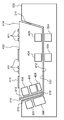
- FIG. 8 is a diagram illustrating the positional relationship between the respective parts of the cradle 300 and the remote controller 420.
- the remote controller 420 includes an infrared receiver 405, an infrared transmitter 406, a magnet 409, an operation unit 411, an IR transistor 408, and an IR window 413.
- the IR transistor 408 is a phototransistor that is turned on by receiving infrared light.
- the IR transistor 408 is disposed inside the IR window 413 and can receive infrared light from the outside through the IR window 413.
- the infrared transmission unit 306 of the cradle 300 sandwiches the infrared reception unit 405 and the IR transistor 408 of the remote control 420, the IR window 313 of the cradle 300, and the IR window 413 of the remote control 420. opposite.
- FIG. 9 is a block diagram showing an electrical configuration of the remote controller 420.
- the remote controller 420 includes a CPU 402, a memory 403, an infrared receiver 405, an infrared transmitter 406, and an IR transistor 408.
- the IR transistor 408 detects the light emission of the infrared transmission unit 306 of the cradle 300 and transmits a detection signal to the CPU 402.
- the infrared receiving unit 405 can receive infrared light (infrared signal), demodulate it, and extract a received signal.
- the infrared receiver 405 can also demodulate a signal in a higher frequency band than the IR transistor 408, but has a higher standby power than the IR transistor 408.
- the IR transistor 408 can only receive signals in a lower frequency band than the infrared receiver 405. For this reason, it is not suitable for receiving an infrared signal whose signal is modulated, but the standby power is lower than that of the infrared receiver 405.
- FIG. 10 is a sequence diagram for explaining the pairing and the operation after pairing in the in-flight monitor system 2.
- the cradle 300 performs pairing by changing the stored remote control 420 from the sleep state to the active state.
- the remote controller 420 transitions to a sleep state.
- the remote controller 420 transitions from the sleep state to the active state when there is a button operation or the like, and transitions from the active state to the sleep state after the operation is completed.
- the remote controller 420 is in a sleep state before pairing.
- the sleep state is a state in which the CPU 402 is not operating and power is not supplied to each unit of the remote controller 420 including the infrared receiving unit 405 and the unit is not operating.
- the IR transistor 408 is turned on when it receives infrared light, and can transmit a detection signal to the CPU 402.
- the operation unit 411 can transmit a signal corresponding to the operation to the CPU 402 when operated by a passenger.
- the active state is a state in which the CPU 402 is operating and power is supplied to each part of the remote control 400.
- the CPU 402 alone has two states: a sleep state in which almost no power is supplied and is not operating, and an active state in which power is supplied and each unit is operating.
- the magnetic sensor 304 provided in the cradle 300 and the magnet 409 provided in the remote controller 420 approach each other. Then, the magnetic sensor 304 detects the magnetic field of the magnet 409 and outputs a detection signal. As a result, the CPU 302 detects the storage of the remote controller 420 (S701). The CPU 302 of the cradle 300 emits (transmits) a return request signal to the remote controller 420 using the infrared transmission unit 306 (S721).
- the return request signal may be any signal as long as it is infrared light that can be detected by the IR transistor 408.
- the return request signal may be a signal that emits light at a constant intensity for a predetermined time.
- the IR transistor 408 receives infrared light (return request signal) and transmits a detection signal to the CPU 402.
- the CPU 402 transitions from the sleep state to the active state.
- the CPU 402 causes the remote controller 420 to transition from the sleep state to the active state by further starting the operation of each unit of the remote controller 420 (S722).
- the remote controller 420 transmits a return signal indicating the transition to the active state to the cradle 300 using the infrared transmission unit 406 (S723). Since steps S702 to S707 are the same as those in the first embodiment, description thereof is omitted. If no operation is performed on the remote controller 420 for a certain period of time after pairing is completed, the CPU 402 causes the remote controller 420 to transition to the sleep state (S708).
- remote controller 420 includes IR transistor 408 that has lower standby power than infrared receiver 405 and receives infrared light.
- the CPU 302 of the cradle 300 causes the infrared transmitter 306 to emit light based on the return request signal in response to the magnetic sensor 304 detecting the storage of the remote controller 420, and then causes the infrared transmitter 306 to operate based on the pairing request signal. Make it emit light.
- the CPU 402 of the remote control 400 transitions to the active state and resumes operation in response to the IR transistor 408 receiving infrared light when in the sleep state.
- the remote controller 420 even when the remote controller 420 is in the sleep state, when it is stored in the cradle 300, it transitions to the active state and pairing is performed. That is, the in-flight monitor system 2 of the present embodiment is effective for easily performing pairing.
- the remote controller 420 transitions to the active state and transmits operation information. In the sleep state, since each unit including the infrared receiving unit 405 is not operating, standby power can be reduced.
- the third embodiment will be described below with reference to FIGS.
- the in-flight monitor system 3 according to the third embodiment is different from the in-flight monitor system 2 according to the second embodiment in that a remote controller 430 including a magnetic sensor 404 is provided instead of the remote controller 420, and a cradle including a magnet is used instead of the cradle 300. 330.
- the same numbers are assigned to configurations similar to those in the second embodiment, and detailed description is omitted.
- FIG. 11 is a diagram showing the positional relationship between the respective parts of the cradle 330 and the remote controller 430.
- the cradle 330 includes a magnetic sensor 304, an infrared receiver 305, an infrared transmitter 306, and a magnet 309.
- the cradle 330 includes a storage unit 311 for storing the remote controller 430 and an IR window 313.
- the storage unit 311 includes a bottom surface 312 and a side surface 315.
- the remote controller 430 includes a magnetic sensor 404, an infrared receiver 405, an infrared transmitter 406, a magnet 409, an IR transistor 408, and an IR window 413.
- the magnetic sensor 404 is disposed inside the bottom surface 412.
- the magnet 309 is disposed inside the bottom surface 312 of the cradle 330.
- the magnet 309 of the cradle 330 and the magnetic sensor 404 of the remote controller 430 face each other with the bottom surface 312 of the cradle and the bottom surface 412 of the remote controller 430 interposed therebetween.
- the magnetic sensor 404 can detect the magnetic field generated by the magnet 309.
- the magnetic sensor 404 is disposed at a distance or orientation that does not detect the magnetic field of the magnet 409.
- the magnetic sensor 304 is disposed at a distance or orientation that does not detect the magnetic field of the magnet 309.
- FIG. 12 is a block diagram showing an electrical configuration of the remote controller 430.
- the remote controller 430 includes a CPU 402, a memory 403, a magnetic sensor 404, an infrared receiver 405, an infrared transmitter 406, an IR transistor 408, an AND gate 410, and an operation unit 411.
- the magnetic sensor 404 detects the magnetic field at the position where the magnetic sensor 404 is placed. When the magnetic field exceeds a certain threshold value, the magnetic sensor 404 transmits a detection signal indicating that the threshold value has been exceeded to the CPU 402.
- the magnetic sensor 404 detects the magnetic field of the magnet 309 provided in the cradle 330 and transmits a detection signal.
- the magnetic sensor 404 is an example of a first storage sensor.
- the IR transistor 408 is an example of a detection element that detects infrared light.
- the IR transistor 408 detects light emission of the infrared transmission unit 306 of the cradle 330.
- FIG. 10 is a sequence diagram for explaining the pairing and the operation after pairing in the in-flight monitor system 3.
- the operation of the in-flight monitor system 3 will be described with reference to FIG.
- step S722 is the same as that of the second embodiment, only step S722 will be described.
- the IR transistor 408 receives infrared light (return request signal) and transmits a detection signal.
- the magnetic sensor 404 detects a magnetic field generated by the magnet 309 of the cradle 330 and transmits a detection signal.
- the AND gate 410 transmits a detection signal to the CPU 402.
- the CPU 402 receives the detection signal from the AND gate 410, the CPU 402 transitions from the sleep state to the active state.
- the CPU 402 causes the remote controller 430 to transition from the sleep state to the active state by further starting the operation of each unit of the remote controller 430 (S722).
- the remote control 430 includes the magnetic sensor 404 that detects that the remote control 430 is stored in the storage unit 311.
- the magnetic sensor 404 detects that the remote controller 430 is housed, and the IR transistor 408 receives the infrared light to transition to the active state and resume operation.
- the in-flight monitor system 3 of the present embodiment is effective for easy pairing. Further, since the conditions when the cradle 330 is housed in the active state are both the detection by the magnetic sensor 404 and the detection by the IR transistor 408, the possibility of erroneous detection can be further reduced.
- an in-flight monitoring system in an aircraft is shown as an example, but this system may be a wireless communication system in transportation equipment such as a bullet train or a bus, which includes a cradle and a remote control.
- the configuration has been described in which the cradle detects the storage of the remote control and starts the pairing operation.
- the in-flight monitor system 1 may be configured such that the remote controller detects the storage in the cradle and starts the pairing operation.
- the configuration and operation related to pairing of the magnetic sensor, infrared transmission unit, infrared reception unit, etc. in the cradle and remote control are opposite to each other, and the remote control detects storage by the magnetic sensor and sends a pairing request signal to the cradle. It may be configured to.
- the configuration using the ID of the remote controller as information for confirming that they are paired with each other has been described.
- the cradle ID may be used as this information.
- the cradle ID is transmitted at the same time as or after the cradle transmits a pairing request signal to the remote controller.
- the remote controller stores the cradle ID in the memory and then sends a completion notification to the cradle.
- the cradle may transmit the cradle ID to the remote controller in response to receiving the pairing request signal.
- the cradle ID is an example of second specifying information.
- the configuration has been described in which the remote controller (first terminal) detects that the remote controller (first terminal) is stored in the storage unit of the cradle (second terminal) and performs pairing.
- the conditions for pairing are not limited to this, and the first terminal and the second terminal can be engaged with each other by a mechanical holding mechanism or magnetic force, and the second terminal detects the engagement instead of the storage sensor.
- the structure provided with a combined sensor may be sufficient.
- the method of detecting storage using magnetism is not limited to this, and a magnetic sensor and a magnet are arranged on one side, and a magnetic body such as an iron plate is arranged on the other side so as to face the magnetic sensor and the magnet. Good.
- the storage sensor is not limited to a magnetic sensor, and a mechanical switch that is switched on / off by storage or an electrical switch that is switched on / off by storage may be used.
- the cradle and the infrared receiver of the remote controller have been described as having a light receiving element and a demodulation circuit, respectively.
- the infrared receiving unit may include only the light receiving element, and the CPU may demodulate based on the infrared signal received by the light receiving element.
- the infrared transmission unit may further include a modulation circuit, and modulate the signal sent from the CPU to cause the LED to emit light.
- the configuration has been described in which the remote control transitions to the sleep state if there is no operation for a certain period of time in the active state.
- the remote controller may transition to the sleep state immediately after completing the necessary operation in the active state.
- the remote control can also perform pairing and post-pairing operations from the active state. For example, if the remote control receives a return request signal in the active state, it transmits the return signal to the cradle as it is. When the operation unit 411 is operated in the active state, operation information corresponding to the operation is transmitted to the cradle as it is.
- the configuration in which the in-flight monitor and the cradle are housed in separate housings and connected via the USB I / F has been described.
- the in-machine monitor and the cradle may be integrated into a single unit.
- the cradle is described as being provided on the back side of the backrest of the aircraft seat.
- the arrangement of the cradle is not limited to this.
- the cradle may be configured to be provided on the upper surface or the side surface of the armrest of the seat behind the seat on which the in-flight monitor is provided.
- an in-flight monitor system including an in-flight monitor, a cradle, and a remote control
- the communication system does not necessarily include an in-flight monitor.
- the device connected to the cradle via the interface is not limited to the in-flight monitor, but may be a projector, headphones, or the like that can express video and sound.
- the communication system may include the first terminal described with the remote control as an example and the second terminal described with the cradle as an example.
- the communication system according to the present disclosure is effective for easy pairing and can be applied to a wireless communication system in an aircraft, a train, or the like.
- In-machine monitor system 200 In-machine monitor 201 Network interface 202 CPU 203 Memory 204 Touch Panel 206 Display 207 USB Interface 300, 330 Cradle 302 CPU 303 Memory 304 Magnetic Sensor 305 Infrared Receiver 305a Light Receiving Element 305b Demodulator 306 Infrared Transmitter 307 USB Interface 309 Magnet 311 Storage Unit 312 Bottom 313 IR Window 315 Side 400, 420, 430 Remote Controller 402 CPU 403 Memory 404 Magnetic sensor 405 Infrared receiver 405a Light receiving element 405b Demodulator circuit 406 Infrared transmitter 408 IR transistor 409 Magnet 410 AND gate 411 Operation unit 412 Bottom 413 IR window 414 Upper surface 415 Side surface 500 Seat
Abstract
Le présent système de communication comporte un premier terminal et un second terminal, qui est muni d'une section de rangement dans laquelle peut être rangé le premier terminal, et qui réalise une communication sans fil avec le premier terminal. Le premier terminal comporte: une première section d'émission de lumière qui émet une lumière infrarouge; une première section de réception de lumière qui reçoit une lumière infrarouge; et un premier contrôleur. Lorsque le premier contrôleur reçoit un signal de demande d'appariement via la première section de réception de lumière, le premier contrôleur fait en sorte que la première section d'émission de lumière émette de la lumière en fonction de premières informations spécifiques. Le second terminal comporte: un second capteur de rangement qui détecte le fait que le premier terminal est rangé; une seconde section d'émission de lumière qui émet une lumière infrarouge; une seconde section de réception de lumière qui reçoit une lumière infrarouge; et un second contrôleur. De façon correspondante à la détection du rangement du premier terminal, ladite détection ayant été effectuée par le second capteur de rangement, le second contrôleur fait en sorte que la seconde section d'émission de lumière émette de la lumière en fonction du signal de demande d'appariement, et lorsque des informations reçues via la seconde section de réception de lumière comprennent les premières informations spécifiques, le second contrôleur effectue une commande correspondant aux informations.
Priority Applications (3)
| Application Number | Priority Date | Filing Date | Title |
|---|---|---|---|
| JP2019508641A JPWO2018179784A1 (ja) | 2017-03-30 | 2018-01-29 | 通信システム |
| EP18776323.0A EP3606086B1 (fr) | 2017-03-30 | 2018-01-29 | Système de communication |
| US16/582,472 US11074809B2 (en) | 2017-03-30 | 2019-09-25 | Communication system |
Applications Claiming Priority (2)
| Application Number | Priority Date | Filing Date | Title |
|---|---|---|---|
| JP2017066979 | 2017-03-30 | ||
| JP2017-066979 | 2017-03-30 |
Related Child Applications (1)
| Application Number | Title | Priority Date | Filing Date |
|---|---|---|---|
| US16/582,472 Continuation US11074809B2 (en) | 2017-03-30 | 2019-09-25 | Communication system |
Publications (1)
| Publication Number | Publication Date |
|---|---|
| WO2018179784A1 true WO2018179784A1 (fr) | 2018-10-04 |
Family
ID=63674882
Family Applications (1)
| Application Number | Title | Priority Date | Filing Date |
|---|---|---|---|
| PCT/JP2018/002747 WO2018179784A1 (fr) | 2017-03-30 | 2018-01-29 | Système de communication |
Country Status (4)
| Country | Link |
|---|---|
| US (1) | US11074809B2 (fr) |
| EP (1) | EP3606086B1 (fr) |
| JP (1) | JPWO2018179784A1 (fr) |
| WO (1) | WO2018179784A1 (fr) |
Cited By (1)
| Publication number | Priority date | Publication date | Assignee | Title |
|---|---|---|---|---|
| JP2019091975A (ja) * | 2017-11-10 | 2019-06-13 | ファナック株式会社 | 操作端末とのペアリング機能を有する外付けデバイス |
Families Citing this family (3)
| Publication number | Priority date | Publication date | Assignee | Title |
|---|---|---|---|---|
| WO2018179784A1 (fr) * | 2017-03-30 | 2018-10-04 | パナソニックIpマネジメント株式会社 | Système de communication |
| US20210393818A1 (en) * | 2020-06-22 | 2021-12-23 | Andrew S. Kanigowski | Embedded ultraviolet disinfection of aircraft interiors |
| CN113301740B (zh) * | 2021-05-07 | 2023-04-28 | 深圳康佳电子科技有限公司 | 一种遥控器收纳装置、电子设备及遥控器收纳方法 |
Citations (7)
| Publication number | Priority date | Publication date | Assignee | Title |
|---|---|---|---|---|
| JP2008228188A (ja) * | 2007-03-15 | 2008-09-25 | Funai Electric Co Ltd | 無線通信システム |
| JP2009253943A (ja) * | 2008-04-11 | 2009-10-29 | Panasonic Corp | ヘッドフォン装置、リモコン装置およびavコンテンツ視聴システム |
| JP2009260934A (ja) | 2008-03-28 | 2009-11-05 | Sharp Corp | 遠隔操作装置、操作対象装置、遠隔操作装置の制御方法、操作対象装置の制御方法、及び遠隔操作システム |
| JP3169436U (ja) * | 2011-05-19 | 2011-07-28 | 旭硝子株式会社 | 識別子読取装置 |
| CN104994614A (zh) * | 2015-05-12 | 2015-10-21 | 杨世旬 | 一种通用的遥控开关 |
| JP2016509701A (ja) * | 2012-12-14 | 2016-03-31 | アンドリュー ハムラ | パーソナル電子デバイス用のラッチ・アンド・キャリー着脱可能メッセンジャ・バッグおよびショルダストラップ・アセンブリ |
| JP2016515024A (ja) * | 2013-03-14 | 2016-05-26 | ニプロ ダイアグナスティックス,インコーポレーテッド | 交換可能なモジュールを備えた測定器 |
Family Cites Families (13)
| Publication number | Priority date | Publication date | Assignee | Title |
|---|---|---|---|---|
| JP4702185B2 (ja) | 2006-05-30 | 2011-06-15 | 船井電機株式会社 | 遠隔制御システム |
| JP2008160627A (ja) | 2006-12-26 | 2008-07-10 | Seiko Instruments Inc | 電子機器及び半導体装置 |
| JP2008263308A (ja) | 2007-04-10 | 2008-10-30 | Sony Corp | リモートコントローラ、電子機器および遠隔操作システム |
| US8965214B2 (en) * | 2007-06-14 | 2015-02-24 | Tria Beauty, Inc. | Manufacturing system and method using IR communications link |
| EP2259603B1 (fr) * | 2008-03-28 | 2015-04-08 | Sharp Kabushiki Kaisha | Dispositif d'actionnement à distance, dispositif devant être actionné, procédé de commande pour dispositif d'actionnement à distance, procédé de commande pour dispositif devant être actionné, et système d'actionnement à distance |
| JP2010200203A (ja) | 2009-02-27 | 2010-09-09 | Sony Corp | リモートコントロール方法およびリモートコントローラ |
| US9584846B2 (en) * | 2011-12-16 | 2017-02-28 | Thales Avionics, Inc. | In-flight entertainment system with wireless handheld controller and cradle having controlled locking and status reporting to crew |
| US9567776B2 (en) * | 2013-06-11 | 2017-02-14 | Invue Security Products Inc. | Anti-theft device for portable electronic device |
| WO2014209135A1 (fr) * | 2013-06-24 | 2014-12-31 | Nigel Greig | Unité de commande de système multimédia de bord |
| US9776511B2 (en) * | 2014-07-08 | 2017-10-03 | Rite-Hite Holding Corporation | Vehicle alignment systems for loading docks |
| FR3046245B1 (fr) * | 2015-12-24 | 2018-02-16 | Partnering 3.0 | Systeme de surveillance de qualite d'air et station d'accueil pour robot mobile equipe de capteurs de qualite d'air |
| WO2017165761A1 (fr) * | 2016-03-24 | 2017-09-28 | Eresearchtechnology, Inc. | Procédés et systèmes permettant de traiter des données de spirométrie |
| WO2018179784A1 (fr) * | 2017-03-30 | 2018-10-04 | パナソニックIpマネジメント株式会社 | Système de communication |
-
2018
- 2018-01-29 WO PCT/JP2018/002747 patent/WO2018179784A1/fr unknown
- 2018-01-29 EP EP18776323.0A patent/EP3606086B1/fr active Active
- 2018-01-29 JP JP2019508641A patent/JPWO2018179784A1/ja active Pending
-
2019
- 2019-09-25 US US16/582,472 patent/US11074809B2/en active Active
Patent Citations (7)
| Publication number | Priority date | Publication date | Assignee | Title |
|---|---|---|---|---|
| JP2008228188A (ja) * | 2007-03-15 | 2008-09-25 | Funai Electric Co Ltd | 無線通信システム |
| JP2009260934A (ja) | 2008-03-28 | 2009-11-05 | Sharp Corp | 遠隔操作装置、操作対象装置、遠隔操作装置の制御方法、操作対象装置の制御方法、及び遠隔操作システム |
| JP2009253943A (ja) * | 2008-04-11 | 2009-10-29 | Panasonic Corp | ヘッドフォン装置、リモコン装置およびavコンテンツ視聴システム |
| JP3169436U (ja) * | 2011-05-19 | 2011-07-28 | 旭硝子株式会社 | 識別子読取装置 |
| JP2016509701A (ja) * | 2012-12-14 | 2016-03-31 | アンドリュー ハムラ | パーソナル電子デバイス用のラッチ・アンド・キャリー着脱可能メッセンジャ・バッグおよびショルダストラップ・アセンブリ |
| JP2016515024A (ja) * | 2013-03-14 | 2016-05-26 | ニプロ ダイアグナスティックス,インコーポレーテッド | 交換可能なモジュールを備えた測定器 |
| CN104994614A (zh) * | 2015-05-12 | 2015-10-21 | 杨世旬 | 一种通用的遥控开关 |
Cited By (2)
| Publication number | Priority date | Publication date | Assignee | Title |
|---|---|---|---|---|
| JP2019091975A (ja) * | 2017-11-10 | 2019-06-13 | ファナック株式会社 | 操作端末とのペアリング機能を有する外付けデバイス |
| US10809773B2 (en) | 2017-11-10 | 2020-10-20 | Fanuc Corporation | External device having pairing functionality with operation terminal |
Also Published As
| Publication number | Publication date |
|---|---|
| EP3606086B1 (fr) | 2020-11-04 |
| EP3606086A1 (fr) | 2020-02-05 |
| EP3606086A4 (fr) | 2020-02-05 |
| US20200020225A1 (en) | 2020-01-16 |
| JPWO2018179784A1 (ja) | 2020-02-06 |
| US11074809B2 (en) | 2021-07-27 |
Similar Documents
| Publication | Publication Date | Title |
|---|---|---|
| WO2018179784A1 (fr) | Système de communication | |
| AU2016100925B4 (en) | Detection and notification of an unpowered releasable charging device | |
| US9590455B2 (en) | Wireless charging system | |
| US9472972B2 (en) | Wireless charging device and method for controlling the same | |
| US9100195B2 (en) | Switch device and power supply control system | |
| CN103106891A (zh) | 显示设备及其控制方法 | |
| US9154828B2 (en) | Method for controlling television device and television control system | |
| KR20110022438A (ko) | 동기 신호 수신 장치 및 그 방법과, 이를 이용한 3d 안경의 셔터 제어 장치 및 방법 | |
| US20140035516A1 (en) | Television low power mode and accessory charging | |
| US20150137614A1 (en) | Non-contact type power supplying apparatus and non-contact type power supplying method | |
| US9210357B1 (en) | Automatically pairing remote | |
| CN103903404A (zh) | 底座和显示装置 | |
| CN106331544B (zh) | 分体电视唤醒系统及唤醒方法 | |
| JP2022099740A (ja) | アクティブスタイラス、電子機器、及びワイヤレス給電システム | |
| US9189956B2 (en) | Remote controller and method of controlling light emission from light-emitting unit thereof | |
| TW201544825A (zh) | 信標裝置、電池殘量通知系統、及信標裝置之控制方法 | |
| KR20100116268A (ko) | 대기 전력 차단 시스템에서 전기 기기의 제어 방법 및 그 장치 | |
| KR20110137956A (ko) | 복수의 제어 대상 기기의 전원을 제어하는 리모콘 및 그 방법 | |
| TWI631030B (zh) | Charging system | |
| KR20150106692A (ko) | 미아방지 장치용 단말기, 신호 감지 단말기, 서버 및 이를 포함한 미아방지 시스템의 동작 방법 | |
| JP2012186694A (ja) | 映像音響システムおよび映像音響送信装置 | |
| JP3208238U (ja) | カメラレンズ用防水コネクタ及びそのアダプタ装置 | |
| WO2023048238A1 (fr) | Dispositif de transmission d'énergie, dispositif de réception d'énergie, procédé de commande et programme | |
| US20220063426A1 (en) | System and method for wireless charging of an electric vehicle | |
| CN108737688B (zh) | 用于电视系统的同步控制装置及其方法 |
Legal Events
| Date | Code | Title | Description |
|---|---|---|---|
| 121 | Ep: the epo has been informed by wipo that ep was designated in this application |
Ref document number: 18776323 Country of ref document: EP Kind code of ref document: A1 |
|
| ENP | Entry into the national phase |
Ref document number: 2019508641 Country of ref document: JP Kind code of ref document: A |
|
| NENP | Non-entry into the national phase |
Ref country code: DE |
|
| ENP | Entry into the national phase |
Ref document number: 2018776323 Country of ref document: EP Effective date: 20191030 |