WO2018174089A1 - 果物の吊り下げ用クリップ - Google Patents
果物の吊り下げ用クリップ Download PDFInfo
- Publication number
- WO2018174089A1 WO2018174089A1 PCT/JP2018/011176 JP2018011176W WO2018174089A1 WO 2018174089 A1 WO2018174089 A1 WO 2018174089A1 JP 2018011176 W JP2018011176 W JP 2018011176W WO 2018174089 A1 WO2018174089 A1 WO 2018174089A1
- Authority
- WO
- WIPO (PCT)
- Prior art keywords
- fruit
- clip
- sub
- holding portion
- main holding
- Prior art date
- Legal status (The legal status is an assumption and is not a legal conclusion. Google has not performed a legal analysis and makes no representation as to the accuracy of the status listed.)
- Ceased
Links
Images




Definitions
- This invention relates to the improvement of the clip which makes it easy to suspend fruit.
- Patent Document 1 There is one shown in Patent Document 1 as a hanging tool for generating dried rice cake having a locking groove into which a handle of the bag can be introduced.
- the main problem to be solved by the present invention is that the fruit can be held more appropriately by the clip.
- a fruit hanging clip a main holding portion for the handle of a fruit with a handle
- a clip for hanging fruit used for producing dried fruit comprising a sub-holding portion for an alternative handle attached to the fruit lacking the handle,
- the sub-holding part is formed at a position where the fruit does not come into contact with the clip when the sub-holding part holds the substitute handle.
- the main holding portion has a split groove shape extending from the upper side to the lower side of the clip,
- One aspect of the present invention is to form the sub-holding portion below the lower end of the groove of the main holding portion so as to communicate with the main holding portion.
- the main holding portion is configured to gradually reduce the groove width as it approaches the lower end of the groove.
- the sub-holding portion has a split groove shape extending in the lateral direction, and the central portion thereof is communicated with the groove lower end of the main holding portion.
- the clip has a vertical intermediate portion positioned between the upper portion and the lower portion, and the lower portion protrudes sideways from the lower end of the intermediate portion,
- One aspect of the present invention is that the main holding portion is formed in the intermediate portion and the sub holding portion is formed in the lower portion.
- the clip has a vertical intermediate portion positioned between the upper portion and the lower portion thereof, and the lower portion protrudes sideways from the lower end of the intermediate portion,
- the sub-holding portion is a protrusion that protrudes upward from the lower portion and is fitted inside a frame-like alternative pattern attached to the fruit.
- the clip can be held more appropriately.
- FIG. 1 is a perspective view of a clip assembly including a fruit hanging clip according to an embodiment of the present invention.
- FIG. 2 is an exploded perspective view of the clip assembly.
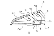
- FIG. 3 is a perspective view of the clip.
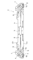
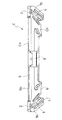
- FIG. 4 is a front view of the clip.
- FIG. 5 is a cross-sectional view taken along the line AA in FIG.
- FIG. 6 is a plan view of the clip.
- FIG. 7 is a bottom view of the clip.
- FIG. 8 is a perspective view showing a fruit lacking a handle and a substitute handle.
- FIG. 9 is a perspective view showing a state in which a substitute pattern is attached to the fruit of FIG.
- FIG. 1 is a perspective view of a clip assembly including a fruit hanging clip according to an embodiment of the present invention.
- FIG. 2 is an exploded perspective view of the clip assembly.
- FIG. 3 is a perspective view of the clip.
- FIG. 4 is a front view of the clip.
- FIG. 5 is
- FIG. 10 is a main part perspective view showing a state in which the fruit to which the substitute pattern body is attached is held in the sub-holding part.
- FIG. 11 is a perspective view of an essential part of a modified example in which the configurations of the clip and the sub-holding part in FIGS. 1 to 10 are different.
- the fruit hanging clip C facilitates the work of hanging the fruit F that is hung and dried and becomes dried fruit such as dried persimmons (if the persimmon is a persimmon fruit). .
- one clip C can hold the fruit F on the left and right. That is, one clip C includes a main holding portion 1 to be described later for the fruit F and a sub holding portion 2 to be described later for the fruit F on the right side and the left side.
- a plurality of clips C having the same size and shape can be connected in the vertical direction to form a clip assembly C ′ having a desired number of stages.
- the clip C includes a jointed portion 3 at a middle position in the left-right direction.
- the jointed part 3 is formed with an upper square hole 3a that penetrates the clip C in the front-rear direction and a lower square hole 3b that penetrates the clip C in the front-rear direction.
- an upper split groove 3c extending to the upper end side with a lower end communicating with the upper square hole 3a is formed. Further, a lower split groove 3d is formed between the lower square hole 3b and the lower end of the jointed portion 3 so that the upper end communicates with the lower square hole 3b and extends to the lower end side.
- a symbol J indicates a rod-shaped joint provided with flanges Ja at both ends.
- the flange portion Ja of the rod-shaped joint J has the upper split groove 3c or the lower split groove between the main portion Jb and the return portion Jc disposed with a gap between the main portion Jb of the rod-shaped joint J.
- a rib-like connecting portion Jd that fits in 3d is provided.
- the rib-shaped connecting portion Jd is fitted into the lower split groove 3d, 2 can be connected to the lower end of the upper clip C in FIG. 2 (FIG. 1).
- the rib-shaped connecting portion Jd is fitted into the upper split groove 3c.
- the lower end of the rod-shaped joint J can be connected to the upper side of the lower clip C in FIG. 2 (FIG. 1).
- the clip assembly C ′ can be configured.
- a hook K can be attached to the lower part of the clip C.
- the hook K includes a hook Ka having the same configuration as the hook Ja of the rod-shaped joint J at the base of the hook main body Kd.
- the hook Ka of the hook K is formed so that the terminal Kc of the return portion Kb faces the terminal Ke of the hook main body Kd.
- the hook portion Ka of the hook K is inserted into the upper rectangular hole 3 a of the uppermost clip C constituting the clip assembly C ′ configured as described above. 2 and the rib-like connecting portion Kf fits into the upper split groove 3c, so that the base side of the hook K can be connected to the upper side of the upper clip C in FIG.
- the hook K connected to the clip assembly C ′ is hooked on a support body (not shown) such as a bar arranged sideways or a string stretched sideways, thereby supporting the clip assembly C ′. It can be hung on the body. That is, in the illustrated example, each of the clips C constituting the clip assembly C ′ configured in this manner holds the fruits F, so that two fruits F are suspended at each stage, and The number of the fruits F multiplied by the number of stages of the clip assembly C ′ can be suspended from the support body with the clip assembly C ′ interposed in one clip assembly C ′. .
- the clip C, rod-shaped joint J, and hook K are typically made of synthetic resin.
- the clip C is a main holding portion 1 for the handle of the fruit F with a handle, A sub-holding unit 2 for the alternative pattern body S attached to the fruit F lacking the handle is used for generating dried fruit F.
- the clip C has an upper portion 4, a lower portion 5, and a longitudinal intermediate portion 6 positioned between the upper portion 4 and the lower portion 5.
- the upper part 4 is long in the left-right direction and protrudes laterally from the upper end of the intermediate part 6.
- the lower part 5 is long in the left-right direction and protrudes laterally from the lower end of the intermediate part 6 in the same direction as the upper part 4.
- the intermediate portion 6 is bent so as to have one bent portion 7 between the upper end and the lower end in a state in which the clip C is cut in a direction orthogonal to the length direction.
- the intermediate part 6 is bent so that the protruding side of the upper part 4 and the lower part 5 is a bent inner side 8 (recessed angle side).
- the horizontal dimension of the lower part 5 is larger than the horizontal dimension of the upper part 4.
- both the left side and the right side of the intermediate part 6 gradually increase in the left and right dimensions of the intermediate part 6 toward the lower end. It becomes the inclined side 6a to be made.
- the intermediate portion 6 has a trapezoidal plate shape that is long in the left-right direction and has a thickness in the front-rear direction having the upper portion 4, the lower portion 5, and the left and right inclined sides 6 a when the clip C is viewed from the front surface Ca.
- the main holding portion 1 has a split groove shape extending from the upper 4 side to the lower 5 side of the clip C.
- the main holding portion 1 is configured to gradually reduce the groove width as it approaches the groove lower end 1b.
- the main holding part 1 is formed in the intermediate part 6.
- the main holding portion 1 is formed between the bent portion 7 of the intermediate portion 6 and the lower end of the intermediate portion 6.
- an introduction opening 9 is formed between the upper end of the intermediate portion 6 and the groove upper end 1a of the main holding portion 1 so as to form a substantially rectangular through-hole shape when the clip is viewed from the front. (See FIG. 4).
- the main holding portion 1 is formed on the center side of the clip C with respect to the inclined side 6a, and its groove center line is substantially parallel to the inclined side 6a. Yes.
- the introduction openings 9 are formed on the left and right sides of the clip C, respectively, and the groove upper ends 1a of the main holding portions 1 communicate with the introduction opening 9 on the left and right sides of the clip C, respectively.
- the right main holding portion 1 communicates the groove upper end 1a with the lower right corner of the right introduction opening 9, and the left main holding portion 1 has the groove upper end 1a. Is communicated with the lower left corner of the left introduction opening 9.
- the introduction opening 9 has the handle Fa (I shape) of the fruit F with only the handle Fa, the handle Fa and the branch Fb (T shape) of the fruit F with the handle Fa and the branch Fb, Or it has the magnitude
- the groove upper end 1a of the main holding part 1 has a width capable of introducing the pattern Fa of the fruit F or the later-described vertical portion Sb of the alternative pattern body S without resistance or with little resistance.
- watermark grooves 10 are formed on the left and right sides of the main holding portion 1 to make the groove wall 1c of the main holding portion 1 thin in the left-right direction (see FIG. 5).
- the pattern Fa of the fruit F and the alternative pattern body S can be introduced into the main holding portion 1 from the back surface Cb side of the clip C through the introduction opening 9. Since the main holding part 1 is configured to gradually reduce the groove width as it approaches the groove lower end 1b, the main holding part 1 has the main handle 1 for the introduced pattern Fa of the fruit F and the substitute pattern body S. The resistance (holding force) increases as the handle Fa of the fruit F or the alternative handle S approaches the groove lower end 1b.
- the pattern Fa of the fruit F is expected to become thinner as the drying progresses, but the handle Fa held by the main holding part 1 is thinned by the weight of the fruit F, and the lower end of the groove of the main holding part 1 Since it moves to 1b side, the situation where drying progresses and the pattern Fa remove
- the lower end 1b of the groove of the main holding part 1 is located on the lower end side of the intermediate part 6, and the fruit F is introduced into the main holding part 1 by placing the fruit Fa on the back Cb side of the clip C.
- the Fc does not come into contact with the clip C in a state where the handle Fa is held by the main holding portion 1.
- the main holding part 1 elastically makes the groove wall 1c elastically widen the groove width when the handle Fa of the fruit F or the substitute pattern body S is introduced into the main holding part 1. A resistance force is applied to the pattern Fa of the fruit F introduced by being deformed and the substitute pattern body S.
- the groove wall 1c of the main holding portion 1 is inclined so as to gradually reduce the groove width of the main holding portion 1 toward the front surface Ca side of the clip C (see FIG. 5). ) The groove wall 1c of the main holding portion 1 is in linear contact with the handle Fa of the fruit F and the alternative handle body S.
- a lightening opening 11 is formed on each of the left and right sides of the jointed part 3 (see FIG. 4).
- the sub-holding portion 2 is formed at a position where the clip C is not brought into contact with the actual Fc of the fruit F when the sub-pattern portion S is held by the sub-holding portion 2.
- the fruit Fa having the pattern Fa with the pattern Fa can be held in the main holding portion 1 and the pattern Fa has been lost in the sub holding portion 2.
- the substitute pattern body S attached to F can be held, and the clip C does not contact the actual Fc of the fruit F lacking the pattern Fa held by the clip C through the substitute pattern body S in this way. Can be.
- the clip C comes into contact with the actual Fc, the actual Fc is damaged and the commercial value is lowered.
- the present clip C such a situation is caused. There is no.
- the clip C is adapted to the substitute pattern body S.
- the alternative pattern body S has a horizontal portion Sa corresponding to the branch Fb and a vertical portion Sb corresponding to the pattern Fa.
- the upper end of the vertical portion Sb is integrated at a position in the middle of the horizontal portion Sa in the left-right direction.
- the substitute pattern body S is attached to the fruit F actual Fc by inserting the lower end of the vertical portion Sb into the fruit F actual Fc.
- the alternative pattern body S is configured by bending a single metal wire rod so as to have a frame shape so as to have an open portion at the lower end of the vertical portion Sb.
- a folded portion Sc is formed projecting leftward and rightward toward the inside of the open portion, and the folded portion Sc is pierced into the actual Fc of the fruit F.
- the sub-holding portion 2 is formed to communicate with the main holding portion 1 below the groove lower end 1b of the main holding portion 1.
- the alternative pattern body S is moved or relatively moved downward along the main holding portion 1 from the state in which the alternative holding body S is introduced into the main holding portion 1.
- the alternative pattern body S can be inserted into the sub-holding portion 2.
- the sub-holding portion 2 has a split groove shape extending in the lateral direction (left-right direction), and its central portion communicates with the groove lower end 1 b of the main holding portion 1.
- the actual Fc of the fruit F is located on the back Cb side of the clip C
- the vertical portion Sb of the substitute pattern body S is located in the main holding portion 1
- the substitute pattern From the state where the alternative handle body S is introduced into the main holding portion 1 so that the laterally facing portion Sa of the body S is positioned on the front surface Ca side of the clip C, the alternative handle body is lowered along the main holding portion 1.
- the vertical portion Sb of the alternative pattern body S can be introduced into the sub-holding unit 2.
- the clip C has a vertical intermediate portion 6 positioned between the upper portion 4 and the lower portion 5, and the lower portion 5 is turned sideways from the lower end of the intermediate portion 6.
- the auxiliary holding part 2 is formed on the lower part 5.
- the horizontal portion Sa is positioned on the upper surface 5a side of the lower portion 5 of the clip C, and the vertical portion Sb is positioned within the sub-holding portion 2.
- the vertically oriented portion Sb can be brought into contact with the intermediate portion 6 of the clip C, and the holding state of the alternative pattern body S by the sub holding portion 2 can be made more stable. it can.
- the fruit F of the fruit F to which the substitute pattern body S is attached is located below the lower surface 5b of the lower part 5 of the clip C, and the fruit Fc does not contact the clip C (FIG. 10).
- the main holding portion 1 and the sub holding portion 2 are formed on the left and right sides of the clip C, respectively. More specifically, in the illustrated example, the left side of the clip C with respect to the right side of the jointed portion 3 is configured to have a line-symmetric shape with the jointed portion 3 as the center.
- FIG. 11 shows a modification of the sub-holding unit 2 of the clip C shown in FIGS.
- the sub-holding portion 2 is a protrusion 2b that protrudes upward from the lower portion 5 and is fitted inside the substitute pattern body S that forms a frame attached to the fruit F.
- the sub-holding portion 2 is a pair of protrusions 2b and 2b that can be fitted into the laterally facing portion of the alternative pattern body S, and is located above the upper surface of the lower portion 5. It is something that protrudes.
- the present invention is not limited to the embodiment described above, and includes all embodiments that can achieve the object of the present invention.
Landscapes
- Food-Manufacturing Devices (AREA)
- Storage Of Fruits Or Vegetables (AREA)
Abstract
柄付きの果物の前記柄に対する主保持部と、前記柄を欠損した前記果物に付設される代替柄体に対する副保持部とを備えた、干し果物の生成に用いられる果物の吊り下げ用クリップである。前記副保持部を、この副保持部に前記代替柄体を保持させたときに、前記果物の実に前記クリップを接触させることがない位置に形成させてなる。
Description
この発明は、果物を吊す作業を容易とするクリップの改良に関する。
柿の柄を導入できる係止溝を備えた干し柿の生成用の吊り具として、特許文献1に示されるものがある。
特許文献1のものでは、収穫時に柄の欠損した柿については、吊り具本体と別体の突き刺し用爪を柿の実に付設し、この突き刺し用爪を利用して吊り具本体の表面側に柿を保持するようになっている。
この発明が解決しようとする主たる問題点は、果物をクリップによって一層適切に保持できるようにする点にある。
前記課題を達成するために、この発明の一態様にあっては、果物の吊り下げ用クリップを、柄付きの果物の前記柄に対する主保持部と、
前記柄を欠損した前記果物に付設される代替柄体に対する副保持部とを備えた、干し果物の生成に用いられる果物の吊り下げ用クリップであって、
前記副保持部を、この副保持部に前記代替柄体を保持させたときに、前記果物の実に前記クリップを接触させることがない位置に形成させてなる、ものとした。
前記柄を欠損した前記果物に付設される代替柄体に対する副保持部とを備えた、干し果物の生成に用いられる果物の吊り下げ用クリップであって、
前記副保持部を、この副保持部に前記代替柄体を保持させたときに、前記果物の実に前記クリップを接触させることがない位置に形成させてなる、ものとした。
前記主保持部は、前記クリップの上部側から下部側に延びる割溝状を呈すると共に、
前記副保持部を、前記主保持部の溝下端の下方に前記主保持部に連通するように形成させることが、この発明の態様の一つとされる。
前記副保持部を、前記主保持部の溝下端の下方に前記主保持部に連通するように形成させることが、この発明の態様の一つとされる。
前記主保持部を、前記溝下端に近づくに連れて溝幅を漸減するように構成させることが、この発明の態様の一つとされる。
前記副保持部を、横向きに延びる割溝状をなし、その中央部を前記主保持部の溝下端に連通させたものとすることが、この発明の態様の一つとされる。
前記クリップは前記上部と前記下部との間に位置される縦向きの中間部を有すると共に、前記下部は前記中間部の下端から横向きに突き出すようになっており、
前記主保持部を前記中間部に形成され、前記副保持部を前記下部に形成させたものとすることが、この発明の態様の一つとされる。
前記主保持部を前記中間部に形成され、前記副保持部を前記下部に形成させたものとすることが、この発明の態様の一つとされる。
前記クリップはその上部とその下部との間に位置される縦向きの中間部を有すると共に、前記下部は前記中間部の下端から横向きに突き出すようになっており、
前記副保持部を、前記下部から上方に突き出すと共に前記果物に付設される枠状をなす代替柄体の内側に嵌め入れられる突部とすることが、この発明の態様の一つとされる。
前記副保持部を、前記下部から上方に突き出すと共に前記果物に付設される枠状をなす代替柄体の内側に嵌め入れられる突部とすることが、この発明の態様の一つとされる。
この発明によれば、クリップによって一層適切に保持することができる。
以下、図1~図11に基づいて、この発明の典型的な実施の形態について、説明する。この実施の形態にかかる果物の吊し用クリップCは、吊されて干されて、干し柿などの干し果物となる果物F(干し柿であれば柿の実)を吊す作業を容易とするものである。
図示の例では、一つのクリップCは、左右にそれぞれ、前記果物Fを保持できるようになっている。すなわち、一つのクリップCは、その右側と左側とにそれぞれ、前記果物Fの後述の主保持部1と、前記果物Fの後述の副保持部2とを備えた構成となっている。
また、図示の例では、同寸同形の複数の前記クリップCを、上下方向に連結して、所望の段数のクリップ集合体C’を構成できるようになっている。
図示の例では、前記クリップCは、その左右方向中程の位置に、被ジョイント部3を備えている。
前記被ジョイント部3には、クリップCを前後方向に貫通する上側方形穴3aと、クリップCを前後方向に貫通する下側方形穴3bとが形成されている。
前記上側方形穴3aと被ジョイント部3の上端との間には、下端を上側方形穴3aに連通させて前記上端側に延びる上側割溝3cが形成されている。また、前記下側方形穴3bと被ジョイント部3の下端との間には、上端を下側方形穴3bに連通させて前記下端側に延びる下側割溝3dが形成されている。
図1および図2において符号Jで示すのは、その両端にそれぞれ鈎部Jaを備えた棒状ジョイントである。
棒状ジョイントJの鈎部Jaは、棒状ジョイントJの主体部Jbとの間に隙間を空けて配される返し部Jcと、主体部Jbとの間に、前記上側割溝3c又は下側割溝3dに嵌まるリブ状連結部Jdを備えている。
図2における上側のクリップCの下側方形穴3bに棒状ジョイントJの上側の鈎部Jaを導入すると共に、前記下側割溝3dにリブ状連結部Jdがはまり込むようにすることで、図2における上側のクリップCの下部側に棒状ジョイントJの上端を接続することができる(図1)。
また、図2における下側のクリップCの上側方形穴3aに棒状ジョイントJの下側の鈎部Jaを導入すると共に、前記上側割溝3cにリブ状連結部Jdがはまり込むようにすることで、図2における下側のクリップCの上部側に棒状ジョイントJの下端を接続することができる(図1)。
このようにすることで、二以上のクリップCを縦方向に、隣り合うクリップCとの間に前記棒状ジョイントJの長さ分の間隔を開けた状態で、連結させて、所望の段数を持ったクリップ集合体C’を構成できるようになっている。
また、図示の例では、前記のように構成されるクリップ集合体C’を構成する最上段のクリップCの上部、あるいは、前記のように構成されるクリップ集合体C’を構成する最下段のクリップCの下部に、フックKを取り付けることができるようになっている。
前記フックKは、フック主体Kdの基部に前記棒状ジョイントJの鈎部Jaと同一構成の鈎部Kaを備えている。このフックKの鈎部Kaは、その返し部Kbの端末Kcを、フック主体Kdの端末Keに向き合わせるように形成されている。
これにより、図示の例では、図1に示されるように、前記のように構成されるクリップ集合体C’を構成する最上段のクリップCの前記上側方形穴3aに前記フックKの鈎部Kaを導入すると共に、前記上側割溝3cにリブ状連結部Kfがはまり込むようにすることで、図2における上側のクリップCの上部側に前記フックKの基部側を接続することができる。
そして、このようにクリップ集合体C’に接続させたフックKを図示しない支持体(横向きに配される棒や横向きに張り込まれる紐など)に引っかけることで、クリップ集合体C’をかかる支持体に吊り下げることができるようになっている。すなわち、図示の例では、このように構成されるクリップ集合体C’を構成する各クリップCにそれぞれ前記果物Fを保持させることで、各段において前記果物Fを2個ずつ吊り下げ、かつ、それにクリップ集合体C’の段数を乗じた数の前記果物Fを、一つのクリップ集合体C’においてこのクリップ集合体C’を介在させて前記支持体に吊り下げることができるようになっている。
前記クリップC、棒状ジョイントJ、フックKは、典型的には、合成樹脂から構成される。
前記クリップCは、柄付きの果物Fの前記柄に対する主保持部1と、
前記柄を欠損した前記果物Fに付設される代替柄体Sに対する副保持部2とを備え、干し果物Fの生成に用いられるものである。
前記柄を欠損した前記果物Fに付設される代替柄体Sに対する副保持部2とを備え、干し果物Fの生成に用いられるものである。
図示の例では、前記クリップCは、上部4と、下部5と、前記上部4と前記下部5との間に位置される縦向きの中間部6を有している。
上部4は左右方向に長く中間部6の上端から横向きに突き出している。
下部5は左右方向に長く前記中間部6の下端から、前記上部4と同じ方向に向けて、横向きに突き出している。
中間部6は、クリップCをその長さ方向に直交する向きに断面にした状態において、その上端と下端との間に一箇所の屈曲部7を持つように屈曲された形態となっている。
中間部6は、前記上部4及び下部5の突き出し側を屈曲内側8(劣角側)とするように、屈曲されている。
図示の例では、前記上部4の左右寸法よりも前記下部5の左右寸法が大きくなっている。これにより、クリップCを前面Ca(前記屈曲内側8の側)から見た状態において(図4)、中間部6の左辺と右辺は共に、下端に向かうに連れて中間部6の左右寸法を漸増させる傾斜辺6aとなっている。図示の例では、中間部6は、クリップCを前面Caから見た状態において、上部4と下部5と左右の傾斜辺6aとを持った左右方向に長く前後方向を厚さとした台形板状を呈している。
前記主保持部1は、前記クリップCの上部4側から下部5側に延びる割溝状を呈している。また、前記主保持部1は、前記溝下端1bに近づくに連れて溝幅を漸減するように構成されている。また、前記主保持部1は前記中間部6に形成されている。
図示の例では、主保持部1は、前記中間部6の屈曲部7と前記中間部6の下端との間に形成されている。
図示の例では、前記中間部6の上端と主保持部1の溝上端1aとの間には、クリップを正面から見た状態で実質的に四角形の貫通穴状をなす導入開口9が形成されている(図4参照)。
また、図示の例では、前記主保持部1は、前記傾斜辺6aよりもクリップCの中央側にあって、その溝中心線を前記傾斜辺6aと実質的に平行とするように形成されている。
図示の例では、前記導入開口9はクリップCの左右にそれぞれ形成されており、クリップCの左右においてそれぞれ、前記主保持部1の溝上端1aが前記導入開口9に連通している。クリップCを前面Caから見た状態において、右側の主保持部1はその溝上端1aを右側の導入開口9の右下隅に連通させており、また、左側の主保持部1はその溝上端1aを左側の導入開口9の左下隅に連通させている。
前記導入開口9は、柄Faのみが付いた前記果物Fのこの柄Fa(I字状)、柄Faと枝Fbとが付いた前記果物Fのこの柄Fa及び枝Fb(T字状)、または、前記代替柄体Sを、抵抗なく導入できる大きさを持っている。
前記主保持部1の溝上端1aは、前記果物Fの柄Fa、または、前記代替柄体Sの後述の縦向き部分Sbを、抵抗なく、あるいは、抵抗少なく導入できる幅を備えている。
また、図示の例では、前記主保持部1の左右にはそれぞれ、前記主保持部1の溝壁1cを左右方向において肉薄にする透かし溝10が形成されている(図5参照)。
前記果物Fの柄Faや前記代替柄体Sは、前記クリップCの背面Cb側から前記導入開口9を通じて、前記主保持部1に導入できる。前記主保持部1は、溝下端1bに近づくに連れて溝幅を漸減するように構成されていることから、導入された前記果物Fの柄Faや前記代替柄体Sに対する主保持部1による抵抗力(保持力)は前記果物Fの柄Faや前記代替柄体Sが溝下端1b側に近づくに連れて大きくなる。前記果物Fの柄Faは乾燥が進むに連れて細くなることが予想されるが、主保持部1に保持される柄Faは果物Fの自重により細くなった分、主保持部1の溝下端1b側に移動されることから、乾燥が進んで主保持部1から柄Faが外れてしまう事態を可及的に防止できる。
前記主保持部1の溝下端1bは中間部6の下端側に位置されており、クリップCの背面Cb側に実を位置させて柄Faを前記主保持部1内に導入した果物Fの実Fcは、主保持部1に前記柄Faを保持させた状態において、クリップCに接触しないようになっている。
また、前記透かし溝により、前記主保持部1は前記果物Fの柄Faや前記代替柄体Sが主保持部1に導入されたとき、溝幅を弾性的に広げるように溝壁1cを弾性変形させて導入された前記果物Fの柄Faや前記代替柄体Sに抵抗力を作用させるようになっている。
また、図示の例では、前記主保持部1の溝壁1cは、クリップCの前面Ca側に向かうに連れて主保持部1の溝幅を漸減させるように傾斜しており、(図5参照)前記果物Fの柄Faや前記代替柄体Sに対して前記主保持部1の溝壁1cは線的に接するようになっている。
なお、図示の例では、前記主保持部1と前記被ジョイント部3との間には、前記被ジョイント部3を挟んだ左右においてそれぞれ、肉抜き開口11が形成されている(図4参照)。
前記副保持部2は、この副保持部2に前記代替柄体Sを保持させたときに、前記果物Fの実Fcに前記クリップCを接触させることがない位置に形成されている。
これにより、この実施の形態にかかるクリップCにあっては、前記主保持部1において柄Fa付きの果物Fの柄Faを保持でき、かつ、前記副保持部2において柄Faを欠損した前記果物Fに付設される代替柄体Sを保持することができると共に、このように代替柄体Sを介してクリップCに保持される柄Faの欠損された果物Fの実FcにクリップCが接触しないようにすることができる。干し果物Fの生成の過程で、前記実FcにクリップCが接触すると、実Fcに傷みなどを生じさせ商品価値を低下させるが、本クリップCにあっては、このような事態を生じさせることはない。
この実施の形態にあっては、クリップCは、前記代替柄体Sに適合するものとなっている。かかる代替柄体Sは、枝Fbに相当する横向き部分Saと、柄Faに相当する縦向き部分Sbとを有している。横向き部分Saの左右方向中程の位置に縦向き部分Sbの上端が一体化されている。かかる代替柄体Sは、縦向き部分Sbの下端を果物Fの実Fcに突き刺して果物Fの実Fcに取り付けられるようになっている。
図示の例では、代替柄体Sは、一本の金属線材を前記縦向き部分Sbの下端に開放部を有するように、枠状をなすように折り曲げることで構成されている。縦向き部分Sbの下端には、左右にそれぞれ開放部の内方に向けて突き出す折り返し部Scが形成されており、この折り返し部Scを果物Fの実Fcに突き刺すようになっている。
この実施の形態にあっては、前記副保持部2は、前記主保持部1の溝下端1bの下方に前記主保持部1に連通するように形成されている。
これにより、この実施の形態にあっては、前記主保持部1に代替柄体Sを導入させた状態から前記主保持部1に沿って下方に代替柄体Sを移動又は相対的に移動させることで、副保持部2に代替柄体Sを入り込ませることができるようになっている。
また、この実施の形態にあっては、前記副保持部2は、横向き(左右方向)に延びる割溝状をなし、その中央部を前記主保持部1の溝下端1bに連通させている。
これにより、この実施の形態にあっては、果物Fの実FcがクリップCの前記背面Cb側に位置し、代替柄体Sの縦向き部分Sbが主保持部1内に位置し、代替柄体Sの横向き部分SaがクリップCの前面Ca側に位置されるように、前記主保持部1に代替柄体Sを導入させた状態から、前記主保持部1に沿って下方に代替柄体Sを移動又は相対的に移動させることで、代替柄体Sの縦向き部分Sbを副保持部2内に導入させることができる。
この実施の形態にあっては、前記クリップCは前記上部4と前記下部5との間に位置される縦向きの中間部6を有すると共に、前記下部5は前記中間部6の下端から横向きに突き出すようになっており、前記副保持部2を前記下部5に形成させている。
副保持部2内に縦向き部分Sbを導入させた代替柄体Sは、クリップCの下部5の上面5a側に横向き部分Saを位置させ、縦向き部分Sbを副保持部2内に位置させる(図10)。この実施の形態にあっては、かかる縦向き部分SbをクリップCの中間部6に接しさせることができ、副保持部2による代替柄体Sの保持状態をより安定的なものとすることができる。代替柄体Sの取り付けられた果物Fの実FcはクリップCの下部5の下面5b下に位置され、かかる実FcはクリップCに接触しない(図10)。
図示の例では、主保持部1及び副保持部2は、クリップCの左右にそれぞれ形成されている。より具体的には、図示の例では、クリップCにおける前記被ジョイント部3を挟んだ右側に対し左側は、この被ジョイント部3を中心とした線対称の形状となるように構成されている。
図11は、図1~図10に示されるクリップCの副保持部2の変更例を示している。この変更例では、前記副保持部2を、前記下部5から上方に突き出すと共に前記果物Fに付設される枠状をなす代替柄体Sの内側に嵌め入れられる突部2bとしている。具体的には、この変更例にあっては、前記副保持部2は、代替柄体Sの横向き部内に嵌め入れ可能な一対の突部2b、2bであって、前記下部5の上面から上方に突き出したものとなっている。
なお、当然のことながら、本発明は以上に説明した実施態様に限定されるものではなく、本発明の目的を達成し得るすべての実施態様を含むものである。
F 果物
Fa 柄
Fc 実
S 代替柄体
C クリップ
1 主保持部
2 副保持部
なお、2017年3月22日に出願された日本国特願2017-055714号の明細書、特許請求の範囲、図面及び要約書の全内容をここに引用し、本発明の明細書の開示として、取り入れるものである。
Fa 柄
Fc 実
S 代替柄体
C クリップ
1 主保持部
2 副保持部
なお、2017年3月22日に出願された日本国特願2017-055714号の明細書、特許請求の範囲、図面及び要約書の全内容をここに引用し、本発明の明細書の開示として、取り入れるものである。
Claims (6)
- 柄付きの果物の前記柄に対する主保持部と、
前記柄を欠損した前記果物に付設される代替柄体に対する副保持部とを備えた、干し果物の生成に用いられる果物の吊り下げ用クリップであって、
前記副保持部を、この副保持部に前記代替柄体を保持させたときに、前記果物の実に前記クリップを接触させることがない位置に形成させてなる、果物の吊り下げ用クリップ。 - 前記主保持部は、前記クリップの上部側から下部側に延びる割溝状を呈すると共に、
前記副保持部を、前記主保持部の溝下端の下方に前記主保持部に連通するように形成させてなる、請求項1に記載の果物の吊り下げ用クリップ。 - 前記主保持部は、前記溝下端に近づくに連れて溝幅を漸減するように構成されてなる、請求項2に記載の果物の吊り下げ用クリップ。
- 前記副保持部は、横向きに延びる割溝状をなし、その中央部を前記主保持部の溝下端に連通させてなる、請求項2又は請求項3に記載の果物の吊り下げ用クリップ。
- 前記クリップは前記上部と前記下部との間に位置される縦向きの中間部を有すると共に、前記下部は前記中間部の下端から横向きに突き出すようになっており、
前記主保持部は前記中間部に形成され、前記副保持部を前記下部に形成させてなる、請求項2~請求項4のいずれか1項に記載の果物の吊り下げ用クリップ。 - 前記クリップはその上部とその下部との間に位置される縦向きの中間部を有すると共に、前記下部は前記中間部の下端から横向きに突き出すようになっており、
前記副保持部を、前記下部から上方に突き出すと共に前記果物に付設される枠状をなす代替柄体の内側に嵌め入れられる突部としてなる、請求項1に記載の果物の吊り下げ用クリップ。
Priority Applications (1)
| Application Number | Priority Date | Filing Date | Title |
|---|---|---|---|
| CN201890000656.5U CN210580767U (zh) | 2017-03-22 | 2018-03-20 | 水果的悬挂用夹子 |
Applications Claiming Priority (2)
| Application Number | Priority Date | Filing Date | Title |
|---|---|---|---|
| JP2017055714A JP6718403B2 (ja) | 2017-03-22 | 2017-03-22 | 果物の吊り下げ用クリップ |
| JP2017-055714 | 2017-03-22 |
Publications (1)
| Publication Number | Publication Date |
|---|---|
| WO2018174089A1 true WO2018174089A1 (ja) | 2018-09-27 |
Family
ID=63586514
Family Applications (1)
| Application Number | Title | Priority Date | Filing Date |
|---|---|---|---|
| PCT/JP2018/011176 Ceased WO2018174089A1 (ja) | 2017-03-22 | 2018-03-20 | 果物の吊り下げ用クリップ |
Country Status (3)
| Country | Link |
|---|---|
| JP (1) | JP6718403B2 (ja) |
| CN (1) | CN210580767U (ja) |
| WO (1) | WO2018174089A1 (ja) |
Citations (10)
| Publication number | Priority date | Publication date | Assignee | Title |
|---|---|---|---|---|
| JPH08196254A (ja) * | 1995-01-27 | 1996-08-06 | Nifco Inc | 干果製造用果吊り具 |
| JPH08294359A (ja) * | 1995-04-27 | 1996-11-12 | Nifco Inc | 干物製造用吊り具 |
| JPH09275926A (ja) * | 1996-02-13 | 1997-10-28 | Yamasa Nousan Kk | 柿クリップ |
| JPH11239445A (ja) * | 1997-12-27 | 1999-09-07 | Yamasa Nousan Kk | 柿つるし具 |
| JP2004298396A (ja) * | 2003-03-31 | 2004-10-28 | Nifco Inc | 干し物の吊し用クリップ |
| JP2005185792A (ja) * | 2003-12-24 | 2005-07-14 | Yamasa Nousan Kk | 柿吊るし具 |
| JP2006280375A (ja) * | 2006-04-05 | 2006-10-19 | Yamasa Nousan Kk | 柿吊るし具 |
| JP2007075078A (ja) * | 2005-09-09 | 2007-03-29 | Wakasaya Sangyo Kk | 干し柿生産省力化吊り具 |
| JP2009219475A (ja) * | 2008-03-14 | 2009-10-01 | Kenichi Yoshikawa | 簡便物干しハンガー |
| JP2017018084A (ja) * | 2015-07-14 | 2017-01-26 | ヤマサ農産有限会社 | 干し果横吊り具 |
-
2017
- 2017-03-22 JP JP2017055714A patent/JP6718403B2/ja active Active
-
2018
- 2018-03-20 CN CN201890000656.5U patent/CN210580767U/zh active Active
- 2018-03-20 WO PCT/JP2018/011176 patent/WO2018174089A1/ja not_active Ceased
Patent Citations (10)
| Publication number | Priority date | Publication date | Assignee | Title |
|---|---|---|---|---|
| JPH08196254A (ja) * | 1995-01-27 | 1996-08-06 | Nifco Inc | 干果製造用果吊り具 |
| JPH08294359A (ja) * | 1995-04-27 | 1996-11-12 | Nifco Inc | 干物製造用吊り具 |
| JPH09275926A (ja) * | 1996-02-13 | 1997-10-28 | Yamasa Nousan Kk | 柿クリップ |
| JPH11239445A (ja) * | 1997-12-27 | 1999-09-07 | Yamasa Nousan Kk | 柿つるし具 |
| JP2004298396A (ja) * | 2003-03-31 | 2004-10-28 | Nifco Inc | 干し物の吊し用クリップ |
| JP2005185792A (ja) * | 2003-12-24 | 2005-07-14 | Yamasa Nousan Kk | 柿吊るし具 |
| JP2007075078A (ja) * | 2005-09-09 | 2007-03-29 | Wakasaya Sangyo Kk | 干し柿生産省力化吊り具 |
| JP2006280375A (ja) * | 2006-04-05 | 2006-10-19 | Yamasa Nousan Kk | 柿吊るし具 |
| JP2009219475A (ja) * | 2008-03-14 | 2009-10-01 | Kenichi Yoshikawa | 簡便物干しハンガー |
| JP2017018084A (ja) * | 2015-07-14 | 2017-01-26 | ヤマサ農産有限会社 | 干し果横吊り具 |
Also Published As
| Publication number | Publication date |
|---|---|
| JP6718403B2 (ja) | 2020-07-08 |
| CN210580767U (zh) | 2020-05-22 |
| JP2018157766A (ja) | 2018-10-11 |
Similar Documents
| Publication | Publication Date | Title |
|---|---|---|
| US6568545B2 (en) | Shipping hanger | |
| US941448A (en) | Flower-pot holder. | |
| USD841183S1 (en) | Window E-chip for an electron microscope | |
| WO2018174089A1 (ja) | 果物の吊り下げ用クリップ | |
| KR200491880Y1 (ko) | 클립을 이용한 천장 점검구 커버 고정구조 | |
| RU2016141583A (ru) | Потолочная подвесная система | |
| KR101379685B1 (ko) | 다용도 선반 | |
| US305861A (en) | Hat and coat hook | |
| CN207320747U (zh) | 电缆槽 | |
| US3709452A (en) | Aperture board hanger bracket | |
| US987416A (en) | Garment-hanger. | |
| US897969A (en) | Picture-hanger. | |
| WO2019073275A1 (en) | LINK FOR CHAIN OF SILVER, JEWELERY, SILVERWARE, FASHION JEWELERY | |
| US9850030B2 (en) | Collapsible box with side wall article supports | |
| CN207225969U (zh) | 悬挂包装及用于悬挂包装的产品包装的悬挂器 | |
| KR101273037B1 (ko) | 미끄럼방지 옷걸이 | |
| CN101146725A (zh) | 保护花茎的花支架 | |
| US1527618A (en) | Metallic clip for attaching metal lath | |
| US911864A (en) | Porcelain cleat. | |
| JP5979106B2 (ja) | コネクタ付電線配列用具 | |
| KR102912981B1 (ko) | 무타공 액자 걸이 | |
| JP6700917B2 (ja) | ハンガー構造および物干し用ハンガー | |
| JP6399624B1 (ja) | ハンガー用補助具 | |
| JP4854294B2 (ja) | 吊下フック | |
| USD1011943S1 (en) | Salt tank monitor |
Legal Events
| Date | Code | Title | Description |
|---|---|---|---|
| 121 | Ep: the epo has been informed by wipo that ep was designated in this application |
Ref document number: 18770773 Country of ref document: EP Kind code of ref document: A1 |
|
| NENP | Non-entry into the national phase |
Ref country code: DE |
|
| 122 | Ep: pct application non-entry in european phase |
Ref document number: 18770773 Country of ref document: EP Kind code of ref document: A1 |