WO2018173743A1 - 可動装置、その製造方法、および、その制御方法 - Google Patents
可動装置、その製造方法、および、その制御方法 Download PDFInfo
- Publication number
- WO2018173743A1 WO2018173743A1 PCT/JP2018/008673 JP2018008673W WO2018173743A1 WO 2018173743 A1 WO2018173743 A1 WO 2018173743A1 JP 2018008673 W JP2018008673 W JP 2018008673W WO 2018173743 A1 WO2018173743 A1 WO 2018173743A1
- Authority
- WO
- WIPO (PCT)
- Prior art keywords
- actuator element
- fixing
- actuator
- fixed
- driven body
- Prior art date
- Legal status (The legal status is an assumption and is not a legal conclusion. Google has not performed a legal analysis and makes no representation as to the accuracy of the status listed.)
- Ceased
Links
Images


Definitions
- the disclosure in this specification relates to a movable device that utilizes deformation of an actuator element.
- Patent Document 1 discloses a movable device that utilizes deformation of an actuator element.
- the deformation of the member is directly or indirectly used to mechanically move the driven body.
- an actuator element is an elongated synthetic fiber.
- the conventional technology fixes a part of the actuator element.
- the deformation amount of the actuator element may not be stable.
- the reference position may be different for each actuator element.
- the conventional technique may shift the reference position for deformation of the actuator element, that is, the zero point. For example, there is a case where unrecoverable deformation accumulates due to long-term use and the reference position is shifted.
- the actuator element when an external force is applied to the actuator element, the actuator element may be forcibly deformed. Such deformation caused by an external force may leave an unrecoverable deformation in the actuator element.
- the load on the actuator element is suppressed. For example, a force by which one actuator element deforms another actuator element becomes a load on one actuator element.
- One object disclosed is to provide a movable device that suppresses problems caused by fixing of an actuator element, a manufacturing method thereof, and a control method thereof.
- Another object of the disclosure is to provide a movable device capable of setting a reference position, a manufacturing method thereof, and a control method thereof.
- Another object of the present disclosure is to provide a movable device that can suppress deformation of an actuator element due to an external force, a manufacturing method thereof, and a control method thereof.
- Another object disclosed is to provide a movable device that suppresses a load on an actuator element, a manufacturing method thereof, and a control method thereof.
- the movable device disclosed herein includes an actuator element that is deformed by an increase or decrease in energy, a fixed portion that fixes a part of the actuator element with respect to the direction of deformation, and a driven part that is connected to another part of the actuator element. And a fixing force at the fixing portion is variable.
- the fixing portion can change the fixing force.
- the fixing force in a part of the actuator element is strong, the other part can output the deformation of the actuator element.
- the fixing force in a part of the actuator element is weak, the displacement in a part of the actuator element is allowed. As a result, inconveniences due to fixing of the actuator element are suppressed.
- the movable device manufacturing method disclosed herein activates the actuator element in a state where a part of the actuator element is fixed, and causes the driven body connected to the other part of the actuator element to be deformed in the actuator element. And a setting step for setting a reference position in the deformation of the actuator element. In the setting step, the actuator element is not opened in a state where a part of the actuator element is opened and in a state where the part is opened. Activating, partially opening the actuator element, and deactivating the actuator element, positioning the actuator element at the reference position, and fixing the actuator element part at the reference position The process of carrying out.
- the actuator element is positioned at the reference position in a state where a part of the actuator element is opened and the actuator element is inactivated. After this, a part of the actuator element is fixed. Therefore, the actuator element outputs a displacement from the reference position.
- the control method for the movable device disclosed herein activates the first actuator element in a state where a part of the first actuator element is fixed, and is connected to the other part of the first actuator element.
- the second actuator element is activated, and the second actuator element is activated.
- the second moving step includes a step of releasing a part of the first actuator element.
- the disclosed control method for a movable device when two actuator elements are used, when one actuator element is driven, the other actuator element is invalidated.
- the first actuator element When the first actuator element is activated, a part of the first actuator element is fixed and a part of the second actuator element is opened. Thereby, when the first actuator element is activated, the load on the first actuator element is suppressed.
- the second actuator element When the second actuator element is activated, a part of the second actuator element is fixed and a part of the first actuator element is opened. Thereby, when the second actuator element is activated, the load on the second actuator element is suppressed.
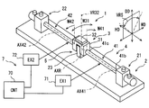
- FIG. 6 is a block diagram illustrating an open state of at least one embodiment. It is a fragmentary sectional view of the movable device concerning at least one embodiment. It is a fragmentary sectional view of the movable device concerning at least one embodiment. It is a perspective view of the movable device concerning at least one embodiment.
- the movable device 1 includes a fixed base 2 and a movable portion 3 that can move mechanically with respect to the base 2.
- the movable part 3 can rotate around a rotation axis AXR extending along the height direction HD.
- the movable part 3 reciprocates a predetermined angular range RG around the rotation axis AXR.
- the movable part 3 has a driven body 31.
- the movement of the movable part 3 is also called rocking.
- the moving direction of the movable part 3 is not restricted to rotation.
- the moving direction of the movable part 3 can be adapted to various movements such as a parallel movement along the height direction HD, a parallel movement along the width direction WD, and a rotational movement around the depth direction DD.
- the movable device 1 has an element 32 mounted on the driven body 31.
- the element 32 provides an electrically active action or an electrically passive action.
- the element 32 is, for example, an electrical light source, an electrical blower, an electrical heat source, an electrical radio wave source, or an electrical magnetic source.
- the element 32 is, for example, an electrical sensor element.
- the movable device 1 may include a connection member that electrically connects the base 2 and the element 32 for electrical connection.
- the element 32 has an axis VR32 for the main function. For example, when the element 32 is a light source, the axis VR32 corresponds to the optical axis. For example, when the element 32 is a sensor, the axis VR32 corresponds to a detection axis.
- the shaft VR32 is swung by the rotation of the driven body 31.
- the axis VR32 is swung within the range of the rotation angle VRS.
- the movable device 1 is also a sensor device.
- the element 32 is a sensor element.
- the element 32 has an axis VR32 indicating a detection direction and a detection range.
- the element 32 detects a physical quantity in the direction of the axis VR32.
- the element 32 is provided by various elements such as an image sensor, an infrared sensor, an ultrasonic sensor, a radar antenna, an electromagnetic wave sensor, and a radiation sensor.
- the element 32 is an infrared sensor installed indoors.
- the detection signal of the element 32 is supplied to a device using infrared information by wire or wireless. Infrared information is supplied and used, for example, to an air conditioner.
- the movable device 1 is installed in a room such as a residence, an office, a vehicle, a ship, and an aircraft, and is used to collect information related to people in the room.
- the base 2 is placed in these rooms.
- the movable device 1 is moved so as to swing the axis VR32.
- the movable device 1 provides a sensor device that moves the axis VR32.
- the movement of the axis VR32 makes it possible to provide various sensor devices such as a directivity direction variable type, a tracking type, or a scanning type.
- a scanning sensor device is provided.
- the axis VR32 rotates about the rotation axis AXR.
- the axis VR32 is movable within a range of a predetermined rotation angle VRS along a plane extending in the width direction WD and the depth direction DD.
- the rotation angle VRS is the scanning range.
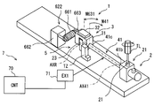
- the movable device 1 includes an actuator mechanism 4.
- the actuator mechanism 4 provides a rotational force for rotating the movable part 3.
- the actuator mechanism 4 is also a power source.
- the actuator mechanism 4 provides a rotational force so as to reciprocate.
- the actuator mechanism 4 has two actuator elements 41 and 42.
- the two actuator elements 41 and 42 are arranged on an extension line of the rotation axis AXR.
- the two actuator elements 41 and 42 are arranged on both sides of the driven body 31.
- the driven body 31 and the two actuator elements 41 and 42 are arranged in series. In the figure, the actuator elements 41 and 42 are illustrated with a little emphasis.
- the first actuator element 41 is connected to the driven body 31 and the fixed portion 21.
- the first actuator element 41 extends along the actuator axis AX41.
- the actuator axis AX41 is also the central axis of the first actuator element 41.
- the actuator shaft AX41 is located on the extension of the rotation shaft AXR.
- the actuator shaft AX41 and the rotation shaft AXR are coaxial.
- the second actuator element 42 is connected to the driven body 31 and the fixed portion 22.
- the second actuator element 42 extends along the actuator axis AX42.
- the actuator axis AX42 is also the central axis of the second actuator element 42.
- the actuator shaft AX42 is located on the extension of the rotation shaft AXR.
- the actuator shaft AX42 and the rotation shaft AXR are coaxial.
- the driven body 31 is disposed at the center of the base 2.
- the fixing portion 21 is provided at one end of the base 2.
- the fixing part 21 is fixed to the base 2.
- the fixing part 22 is provided at the other end of the base 2.
- the fixing part 22 is fixed to the base 2.
- the base 2 is made of a material that can maintain the shape of the movable device 1 against the force generated by the actuator mechanism 4.
- the base 2 is made of metal or resin. Part or the whole of the base 2 may be provided by a printed wiring board.
- the first actuator element 41 and the second actuator element 42 are arranged symmetrically with respect to the driven body 31.
- the first actuator element 41 and the second actuator element 42 have a symmetrical structure.
- the first actuator element 41 will be described. This description can be referred to as a description of the second actuator element 42.
- the first actuator element 41 has a fixed end 41 b that can be connected to the fixed portion 21.
- the fixed end 41b is connected to the fixed portion 21 when at least the first actuator element 41 outputs rotational power.
- the first actuator element 41 has an output end 41 c that can be connected to the driven body 31.
- the output end 41c is connected to the driven body 31 when at least the first actuator element 41 outputs rotational power.
- the driven body 31 is connected to the actuator element 41 on the actuator shaft AX41.
- the names of the fixed end 41b and the output end 41c are for convenience. In the following description, the fixed end 41b and the output end 41c may be simply referred to as ends.
- the first actuator element 41 has a rod shape.
- the first actuator element 41 has a shape that can be called an elongated rod shape or a fiber shape.
- the first actuator element 41 can be formed in a columnar shape or a cylindrical shape.
- the movable device 1 has a guide mechanism 5 for guiding the movement of the movable part 3.
- the guide mechanism 5 is provided between the support portion 23 provided on the base 2 and the driven body 31.
- the support part 23 is fixed to the base 2.
- the guide mechanism 5 allows the rotational movement of the driven body 31 around the height direction HD.
- the guide mechanism 5 suppresses the rotational motion around the depth direction DD and the rotational motion around the width direction WD.
- the guide mechanism 5 suppresses the vertical movement in the depth direction DD and the horizontal movement in the width direction WD of the movement of the driven body 31.
- the guide mechanism 5 may suppress the back-and-forth movement in the height direction HD.
- the guide mechanism 5 may allow back-and-forth movement in the height direction HD.
- the height direction HD can be defined as the roll axis, the width direction WD as the pitching axis, and the depth direction DD as the yaw axis.
- the guide mechanism 5 allows the driven body 31 to roll.
- the guide mechanism 5 may suppress excessive roll movement exceeding the available range. For example, a direct collision between the driven body 31 and the support portion 23 or an indirect collision via an elastic member limits the roll motion range.
- the guide mechanism 5 suppresses yawing motion and pitching motion of the driven body 31. Further, the guide mechanism 5 suppresses the vertical and horizontal movements of the driven body 31.
- the guide mechanism 5 may suppress the back-and-forth movement of the driven body 31.
- the guide mechanism 5 may allow the back-and-forth movement of the driven body 31 in some cases.
- the movable device 1 includes a control system 7.
- the control system 7 includes a control device (CNT) 70 and energy increase / decrease devices (EX1, EX2) 71, 72.
- the energy increasing / decreasing devices 71, 72 are devices that increase / decrease the energy of the two actuator elements 41, 42 in order to extract mechanical motion from the two actuator elements 41, 42.
- the energy increasing / decreasing devices 71 and 72 increase or decrease the energy of the two actuator elements 41 and 42 so as to rotate the two actuator elements 41 and 42.
- the control device has at least one arithmetic processing unit (CPU) and at least one memory device as a storage medium for storing programs and data.
- the control device is provided by a microcomputer including a computer-readable storage medium.
- the storage medium is a non-transitional tangible storage medium that stores a computer-readable program in a non-temporary manner.
- the storage medium can be provided by a semiconductor memory or a magnetic disk.
- the controller can be provided by a computer or a set of computer resources linked by a data communication device.
- the program is executed by the control device to cause the control device to function as the device described in this specification and to cause the control device to perform the method described in this specification.
- the control system has a plurality of signal sources that supply signals indicating information input to the control device as input devices.
- the control system acquires information by the control device storing the information in the memory device.
- the control system has a plurality of control objects whose behavior is controlled by the control device as output devices.
- the control system controls the behavior of the control object by converting information stored in the memory device into a signal and supplying the signal to the control object. For example, the control device acquires an operation signal and a stop signal from the outside, and intermittently activates the energy increasing / decreasing devices 71 and 72 to cause the movable device 1 to swing.
- control device, signal source, and control object included in the control system provide various elements. At least some of these elements can be referred to as blocks for performing functions. In another aspect, at least some of these elements can be referred to as modules or sections that are interpreted as configurations. Furthermore, the elements included in the control system can also be referred to as means for realizing the functions only when intentional.
- the means and / or function provided by the control system can be provided by software recorded in a substantial memory device and a computer that executes the software, software only, hardware only, or a combination thereof.
- the controller can be provided by an electronic circuit that is hardware, it can be provided by a digital circuit including a number of logic circuits, or an analog circuit.
- the two actuator elements 41 and 42 are actively deformed in one direction.
- the deformation directions of the two actuator elements 41 and 42 are opposite directions, that is, symmetrical directions.
- an active deformation is obtained in both directions, i.e. in a reciprocating direction.
- Actuator elements 41 and 42 are deformed around actuator axes AX41 and AX42 by increasing or decreasing thermal energy.
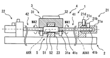
- the first actuator element 41 is deformed so as to be twisted when the temperature of the first actuator element 41 rises. Since the fixed end 41b is fixed by the fixing portion 21, the driven body 31 rotates in the direction of the arrow M41 that is the first direction.
- the second actuator element 42 is deformed so as to be twisted when the temperature of the second actuator element 42 rises. Since the fixed end 42b is fixed by the fixing portion 22, the driven body 31 rotates in the direction of the arrow M42 that is the second direction.
- the direction of the arrow M41 and the direction of the arrow M42 are symmetric with respect to the driven body 31. As a result, the driven body 31 rotates over the angular range indicated by the arrow M31.
- the arrow M31 corresponds to the rotation angle VRS of the axis VR32.
- the actuator elements 41 and 42 and the energy increasing / decreasing devices 71 and 72 that can be used in this embodiment include those described in JP-A-2016-42783.
- the content described in Japanese Patent Application Laid-Open No. 2016-42783 is incorporated by reference as an explanation of technical elements in this specification.
- the actuator elements 41 and 42 can be provided by various materials called artificial muscles. For example, materials such as synthetic resins, metals, shape memory alloys, and organic materials can be used.
- One example of the actuator elements 41 and 42 is a synthetic fiber.
- the synthetic fiber extends along an extension line of the rotation axis AXR.
- Synthetic fibers are elongated.
- Synthetic fibers are called polymer fibers.
- One typical example of a polymer fiber is a monofilament resin.
- the monofilament resin includes a polyamide resin and a polyethylene resin.
- a polymer fiber called nylon or polyethylene may have a torsional deformation amount with respect to a temperature change, and can be used as the actuator elements 41 and 42.
- the polymer forming the polymer fiber is oriented so as to extend along the actuator axes AX41 and AX42.
- the polymer may have a “twist” around the actuator axes AX41, AX42.
- the term “twist” may refer to a twist in a single fiber and may refer to a twist between multiple fibers.
- the twist deformation amount with respect to the temperature change of the polymer fiber may appear strongly along the direction of “twist” in the single fiber.
- the actuator elements 41 and 42 are single fibers.
- the amount of torsional deformation with respect to temperature change of the polymer fiber may appear along the direction of “twist” between the plurality of fibers.
- the actuator elements 41 and 42 may be a bundle of a plurality of polymer fibers twisted together.
- One example of the actuator elements 41 and 42 is a shape memory alloy.
- Shape memory alloys extending along the actuator axes AX41, AX42 can be used.
- the shape memory alloy can be used in various shapes such as a single rod shape and a coiled shape.
- the shape of the shape memory alloy is selected so as to obtain a torsional deformation amount with respect to a temperature change.
- the energy increase / decrease devices 71 and 72 change the energy state of the actuator elements 41 and 42 bidirectionally between the high energy state and the low energy state.
- the energy increasing / decreasing devices 71 and 72 can apply and remove energy electrically, optically, magnetically, electromagnetically, or radiationally.
- the application and removal of electrical energy includes an increase or decrease in electrical heat, an increase or decrease in current, an increase or decrease in electric field, or an increase or decrease in charge.
- the temperature can be increased by applying light, and the temperature can be decreased by blocking light.
- Energy application and removal can be performed directly or indirectly.
- energy may be applied by an energy transmission component that directly contacts the actuator elements 41 and 42, or energy may be indirectly applied by an energy transmission component installed away from the actuator elements 41 and 42.
- the energy transmission component can be provided by, for example, an electrical heating member.
- the energy increasing / decreasing devices 71, 72 increase the thermal energy of the actuator elements 41, 42.
- the increase in thermal energy is realized, for example, by supplying current to the heat generating members provided in the actuator elements 41 and 42.
- the energy increasing / decreasing devices 71 and 72 decrease the thermal energy of the actuator elements 41 and 42 in order to return the actuator elements 41 and 42 from active rotation.
- the reduction of the thermal energy is realized, for example, by interrupting the current supply to the heat generating members provided in the actuator elements 41 and 42 to dissipate heat.
- the fixing portion 21 and the fixing portion 22 are arranged symmetrically with respect to the driven body 31.
- the fixed part 21 and the fixed part 22 have a symmetrical structure.
- the driven body 31 has a symmetrical structure with respect to the guide mechanism 5.
- portions related to the first actuator element 41 will be described. This description can be referred to as a description of portions related to the second actuator element 42.
- parts related to the first actuator element 41 there are a fixed portion 21 and a third coupling mechanism 31 c provided on the driven body 31.
- the fixing portion 21 has an end sleeve 21a and an anchor block 21c.
- the end sleeve 21 a is connected to the end of the actuator element 41.
- the end sleeve 21a is fixed to the anchor block 21c.
- the anchor block 21 c is fixed to the base 2.
- the end sleeve 21 a is a cylindrical member coaxial with the actuator element 41.
- the end sleeve 21a may be a polygonal rectangular tube.
- the end sleeve 21 a has an inner hole that receives the fixed end 41 b of the actuator element 41.
- the end sleeve 21a includes a first connecting mechanism 21b that connects the fixed end 41b and the end sleeve 21a.
- the first coupling mechanism 21b couples the fixed end 41b and the end sleeve 21a with respect to the circumferential direction of the actuator shaft AX41 when at least the actuator element 41 outputs turning force.
- the first connecting mechanism 21b is provided by an inner hole and a set screw.
- the set screw is provided in the radial direction toward the inner hole of the end sleeve 21a.
- the set screw connects the fixed end 41b and the end sleeve 21a in the axial direction and the circumferential direction by tightening the fixed end 41b in the radial direction.
- the first coupling mechanism 21b can be provided by various mechanisms.
- the first connecting mechanism 21b can be provided by a plurality of set screws arranged radially, a chuck mechanism for fastening the fixed end 41b in the radial direction, a caulking sleeve for fastening the fixed end 41b in the radial direction, and the like.
- the first connecting mechanism 21b may allow the axial movement of the fixed end 41b relative to the end sleeve 21a along the actuator axis AX41.
- the fixed end 41b and the end sleeve 21a may be coupled so that the fixed end 41b can move in the axial direction within a limited range.
- an elastic member such as a spring or rubber can be used.
- the first connection mechanism 21b may be provided by a mechanism that can be opened and closed.
- the first coupling mechanism 21b can be provided by an electromagnetic mechanism that can switch between a state in which the fixed end 41b is fixed in the circumferential direction and a state in which the fixed end 41b is rotatable in the circumferential direction. .
- the anchor block 21c has an inner hole for receiving the end sleeve 21a.
- the anchor block 21c has a second coupling mechanism 21d that couples the end sleeve 21a and the anchor block 21c.
- the second coupling mechanism 21d couples the end sleeve 21a and the anchor block 21c with respect to the circumferential direction of the actuator shaft AX41 when at least the actuator element 41 outputs turning force.
- the second connecting mechanism 21d is provided by an inner hole and a set screw.
- the set screw is provided in the radial direction toward the inner hole of the anchor block 21c.
- the set screw couples the end sleeve 21a and the anchor block 21c in the axial direction and the circumferential direction by tightening the end sleeve 21a in the radial direction.
- the second connecting mechanism 21d can be provided by various mechanisms.
- the second connecting mechanism 21d can be provided by a plurality of set screws arranged radially, a chuck mechanism that tightens the end sleeve 21a in the radial direction, a caulking sleeve that tightens the end sleeve 21a in the radial direction, and the like.
- the second connecting mechanism 21d may allow the end sleeve 21a to move in the axial direction along the actuator axis AX41.
- the anchor block 21c and the end sleeve 21a may be coupled so that the end sleeve 21a can move in the axial direction within a limited range.
- the second connecting mechanism 21d may be provided by a mechanism that can be opened and closed.
- the second coupling mechanism 21d is an electromagnetic mechanism capable of switching between a state in which the end of the actuator element 41 is fixed in the circumferential direction and a state in which the end of the actuator element 41 is rotatable in the circumferential direction. Can be provided.
- the driven body 31 has an inner hole that receives the output end 41 c of the actuator element 41.
- the driven body 31 includes a third connecting mechanism 31a that connects the driven body 31 and the output end 41c.
- the third connecting mechanism 31a connects the output end 41c and the driven body 31 with respect to the circumferential direction of the actuator shaft AX41 when at least the actuator element 41 outputs rotational power.
- the third coupling mechanism 31a is provided by an inner hole and a set screw.
- the set screw is provided in the radial direction toward the inner hole of the driven body 31.
- the set screw connects the driven body 31 and the output end 41c with respect to the axial direction and the circumferential direction by tightening the output end 41c in the radial direction.
- the third coupling mechanism 31a can be provided by various mechanisms.
- the third coupling mechanism 31a can be provided by a plurality of set screws arranged radially, a chuck mechanism that tightens the output end 41c in the radial direction, a caulking sleeve that tightens the output end 41c in the radial direction, and the like.
- the third coupling mechanism 31a may allow the output end 41c to move in the axial direction with respect to the driven body 31 along the actuator axis AX41.
- the output end 41c and the driven body 31 may be coupled so that the output end 41c can move in the axial direction within a limited range.
- an elastic member such as a spring or rubber can be used.
- the third connection mechanism 31a may be provided by a mechanism that can be opened and closed.
- the third coupling mechanism 31a can be provided by an electromagnetic mechanism capable of switching between a state in which the output end 41c is fixed in the circumferential direction and a state in which the output end 41c is rotatable in the circumferential direction. .
- the driven body 31 is rotatably supported by the guide mechanism 5.
- the guide mechanism 5 has a shaft 51 and a guide bore 52.
- the shaft 51 is provided by a coaxial cylindrical member having a rotation axis AXR.
- the shaft 51 is fixed to the driven body 31. Both ends of the shaft 51 are fixed to the driven body 31.
- the driven body 31 has a shaft 51.
- the guide bore 52 is provided in the support portion 23.
- the support portion 23 has a guide bore 52.
- the support portion 23 is a member for supporting the driven body 31.
- the support part 23 is fixed to the base 2.
- the support part 23 is a block.
- the guide bore 52 is provided by a through hole that penetrates the support portion 23.
- the guide bore 52 receives the shaft 51.
- the guide bore 52 allows the shaft 51 to rotate.
- the support unit 23 supports the driven body 31 in a rotatable manner.
- the outer surface of the shaft 51 and the inner surface of the guide bore 52 are in partial contact.
- the outer surface of the shaft 51 and the inner surface of the guide bore 52 slide with each other when the driven body 31 rotates.
- the driven body 31 is guided around the shaft 51.
- the members that provide the shaft 51 and guide bore 52 are made of a low friction material.
- the member that provides the shaft 51 or the guide bore 52 may be made of a low friction material. Friction between the shaft 51 and the guide bore 52 is suppressed.
- the support part 23 is opposed to the driven body 31 at both end faces thereof.
- the support part 23 is in partial contact with the driven body 31 at both end faces thereof.
- the support portion 23 and the driven body 31 slide with each other when the driven body 31 rotates.
- the heat of the actuator element 41 is radiated from the entire actuator element 41 to the external environment.
- the heat of the actuator element 41 is radiated from the fixed end 41 b via the fixed portion 21.
- the first connecting mechanism 21b and the second connecting mechanism 21d contribute to lowering the thermal resistance of the heat dissipation path.
- the heat of the actuator element 41 is radiated from the output end 41 c via the driven body 31.
- the heat of the actuator element 41 may be radiated from the output end 41 c via the driven body 31, the support portion 23, and the base 2.
- the third coupling mechanism 31a contributes to lower the thermal resistance of the heat dissipation path.
- the contact between the driven body 31 and the support portion 23 and / or the contact between the shaft 51 and the guide bore 52 also contributes to lowering the thermal resistance of the heat dissipation path.
- the heat of the actuator element 41 is radiated from the output end 41 c via the driven body 31, the contact between the driven body 31 and the support portion 23, and the support portion 23.
- the heat of the actuator element 41 is radiated from the output end 41 c through the driven body 31 through the shaft 51, the contact between the shaft 51 and the guide bore 52, and the support portion 23.
- the actuator element 41 radiates heat via the driven body 31 and the guide mechanism 5.
- the actuator element 41 has a material wire 41a, a fixed end 41b, an output end 41c, and a heating wire 41d.
- the material wire 41a is the above-described polymer fiber.
- the heating wire 41 d is also a part of the energy increasing / decreasing device 71.
- the heating wire 41d is also an energy transmission component for increasing or decreasing the energy of the material wire 41a.
- the heating wire 41d is disposed directly or indirectly on the surface of the material wire 41a.
- the heating wire 41d has a spiral shape or a coil shape.
- the heating wire 41d is a metal wire that generates heat when energized.
- the heating wire 41d can be provided by a platinum wire, a copper wire, or the like.
- the heating wire 41d is provided by a nichrome wire.
- the heating wire 41d can be provided by a round wire, a square wire, or a metal foil.
- the heating wire 41d is affixed to the surface of the material wire 41a.
- the heating wire 41d generates heat when energized.
- the heat supplied by the heating wire 41d is transmitted to the material wire 41a, and raises the temperature of the material wire 41a.
- the heating wire 41d stops generating heat when energization is interrupted.
- the heat of the material wire 41a is radiated to the external environment.
- the third coupling mechanism 31a and the guide mechanism 5 at the output end 41c contribute to heat dissipation. For this reason, a large temperature difference can be realized in the actuator element 41.
- control process 180 for swinging the driven body 31 is illustrated.
- the control process 180 is a part of the control process in the control device 70.
- step 181 it is determined whether the swing of the movable device 1 is required (ON) or not (OFF). For example, when it is required to operate a scanning infrared sensor, the swing is turned on. When it is not required to operate the scanning infrared sensor, the swing is turned off. If the swing is OFF, the control is terminated. If the swing is ON, the process proceeds to a loop process in steps 182 and 183.
- Step 182 is a process for heating the first actuator element 41.
- Step 183 is a process for heating the second actuator element 42. By alternately repeating Step 182 and Step 183, the driven body 31 operates in a swinging manner.
- step 184 it is determined whether the swing of the movable device 1 is required (ON) or not (OFF).
- Step 182 is a process of rotating the driven body 31 in the forward rotation direction.
- the forward rotation direction is a direction in which the driven body 31 is rotated in the clockwise direction when viewed from the first actuator element 41.
- Step 182 includes step 185 and step 186.
- step 185 first, the first actuator element 41 is activated.
- step 185 the heating wire 41d of the first actuator element 41 is energized.
- the control device 70 energizes the heating wire 41d from the energy increasing / decreasing device 71.
- the process of step 185 is executed so that the first actuator element 41 outputs a twist of a predetermined angle in the forward rotation direction.
- the rotation angle of the driven body 31 is detected by the rotation angle sensor, and step 185 is continued until a predetermined angle of rotation is obtained.
- the process of step 185 may be continued for a predetermined time by a timer process.
- step 186 the first actuator element 41 is inactivated.
- step 186 energization to the heating wire 41d of the first actuator element 41 is cut off.
- the control device 70 cuts off the power supply from the energy increasing / decreasing device 71 to the heating wire 41d.
- Step 183 is a process of rotating the driven body 31 in the reverse direction.
- Step 183 includes step 187 and step 188.
- step 187 first, the second actuator element 42 is activated.
- step 187 the heating wire of the second actuator element 42 is energized.
- the control device 70 energizes the heating wire from the energy increasing / decreasing device 72.
- step 188 the second actuator element 42 is deactivated.
- step 188 energization to the heat generating wire of the second actuator element 42 is cut off.
- the control device 70 cuts off the power supply from the energy increasing / decreasing device 72 to the heating wire.
- activation corresponds to energization to the heating wire 41d.
- Inactivation corresponds to the interruption of energization to the heating wire 41d.
- Activation and deactivation word pairs can be associated with heating and heat dissipation word pairs, energization and deactivation word pairs, and active and standby word pairs.
- the control device 70 controls the energy increasing / decreasing device 71 so as to alternately repeat a period in which the energy of the actuator element 41 increases and a period in which the energy of the actuator element 41 decreases.
- the two actuator elements 41 and 42 are actively driven alternately.
- the first actuator element 41 actively outputs a torsional deformation in the forward rotation direction
- the second actuator element 42 is passively driven in the forward rotation direction.
- the second actuator element 42 is actively outputting torsional deformation in the reverse rotation direction
- the first actuator element 41 is passively driven in the reverse rotation direction. Since two actuator elements 41, 42 are used and are driven alternately, a stable rotational output is obtained in both directions.
- the quiet movable device 1 can be provided. This is particularly advantageous when the movable device 1 is used in a device installed indoors. For example, a quiet scanning infrared sensor can be obtained. Since the movable device 1 includes the guide mechanism 5, vibration of the driven body 31 is suppressed. In particular, vibrations in the direction intersecting the rotation axis AXR, that is, the vertical direction and the horizontal direction with respect to the rotation axis AXR are suppressed. Since the guide mechanism 5 defines a rotation axis AXR that is coaxial with the actuator axis AX41, the torsional deformation of the actuator element 41 can be directly taken out. Further, the guide mechanism 5 contributes to heat dissipation of the actuator element 41.
- FIG. 5 shows a calibration process 190 in the manufacturing method or adjustment method of the movable device. Each step is executed by a manufacturer or an operator.
- the calibration process 190 provides a setting process for setting a deformation reference when the actuator elements 41 and 42 are at the reference position.
- the calibration process 190 corrects the reference position.
- step 191 the calibration process 190 determines whether calibration of the reference position is necessary. If calibration is not necessary, the process ends. If calibration is required, go to step 192.
- step 192 the fixing portions 21 and 22 are operated so as to open the fixed ends 41b (part) of the actuator elements 41 and 42.
- the coupling mechanism 21d is operated so that the actuator elements 41 and 42 can rotate around the actuator axes AX41 and AX42, that is, loosen the fixing force.
- the actuator elements 41 and 42 are inactivated in a state where the fixed end 41b is opened. Thereby, the driven body 31 can be rotated without being restrained by the fixing portions 21 and 22. Therefore, step 192 provides a step of opening the fixed end 41b and a step of deactivating the actuator elements 41 and 42 in a state where the fixed end 41b is opened.
- Step 193 the actuator elements 41 and 42 are positioned at the reference position.
- the fixed end 41b is in an open state.
- the actuator elements 41 and 42 are in an inactivated state. Therefore, Step 193 provides a step of positioning the actuator elements 41 and 42 at the reference position in a state where the fixed end 41b is opened and the actuator elements 41 and 42 are inactivated.
- step 194 the fixing portions 21 and 22 are operated so as to fix the fixed ends 41b of the actuator elements 41 and 42.
- the actuator elements 41 and 42 are positioned at the reference position. Therefore, step 194 provides a step of fixing the fixed end 41b in a state where the actuator elements 41 and 42 are positioned at the reference position.
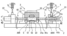
- FIG. 6 shows the movable device 1 in step 193.
- the fixing force in the fixing parts 21 and 22 is variable.
- the fixing force is manually variable.
- the fixing portions 21 and 22 can be switched between a fixed state in which the fixed end 41b is fixed and an open state in which the fixed end 41b is opened.
- the fixing force by the fixing parts 21 and 22 is variable by the connecting mechanism 21d.
- the coupling mechanism 21d can be adjusted using the tool TL. Specifically, when the set screw is loosened with the tool TL, the fixing force is weakened. When the set screw is loosened, the end sleeve 21a can rotate around the actuator axis AX41. When the set screw is tightened with the tool TL, the fixing force is increased. When the set screw is tightened, the end sleeve 21a is fixed so as not to rotate around the actuator shaft AX41.
- the reference position specifying device TZ is used.
- the reference position specifying device TZ is applied to the base 2 and the driven body 31 and fixes the attitude of the driven body 31 with respect to the base 2 to the reference position.
- the actuator elements 41 and 42 fixed to the driven body 31 are also positioned at the reference position.
- the position where the element 32 points in a predetermined direction is the reference position.
- FIG. 7 shows the state in step 193.
- the fixing portions 21 and 22 open the actuator elements 41 and 42.
- the reference position specifying device TZ is in contact with the driven body 31.
- the movable device 1 includes the reference position specifying unit TZ.
- the reference position specifying device TZ positions the actuator elements 41 and 42 at the reference position when the fixing force by the fixing portions 21 and 22 is weakened and the actuator elements 41 and 42 are movable in the deformation direction.
- the moving steps 182 and 183 and the setting step 190 are provided.
- the actuator elements 41 and 42 are activated in a state where the fixed end 41b which is a part of the actuator elements 41 and 42 is fixed.
- the driven body 31 connected to the output end 41c, which is another part of the actuator elements 41 and 42 is moved by deformation generated in the actuator elements 41 and 42.
- the deformation reference is set when the actuator elements 41 and 42 are at the reference position.
- the setting process is also called an initial value setting process.
- Embodiment which is a modification which makes previous embodiment a basic form is described.
- the reference position specifying unit TZ is used.
- this embodiment includes an automatic return function in which the driven body 31 automatically moves to the reference position.
- the automatic return function is realized by the reference position specifying device 2TZ that is a weight.
- the driven body 31 includes a reference position specifying device 2TZ that is a weight.
- the reference position specifying device 2TZ rotates the driven body 31 using gravity.
- the calibration process includes a step of positioning the base 2 in a reference state, for example, a horizontal state.
- the fixing force by the fixing parts 21 and 22 is loosened.
- the reference position specifying device TZ rotates the driven body 31 by gravity.
- the actuator elements 41 and 42 are rotated together with the driven body 31 and positioned at the reference position.
- the reference position specifying device 2TZ has the actuator elements 41 and 42 at the reference position when the fixing force by the fixing portions 21 and 22 is weakened and the actuator elements 41 and 42 are movable in the deformation direction. Position it.
- Embodiment which is a modification which makes previous embodiment a basic form is described.
- gravity is used to provide an automatic return function.
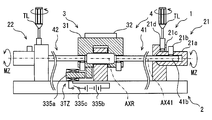
- an electrical reference position specifying device 3TZ is used to stop the driven body 31 at the reference position.
- the reference position specifying device 3TZ includes an electromagnet 335a fixed to the base.
- the electromagnet 335a When the electromagnet 335a is excited, the electromagnet 335a pulls a magnetic portion provided in the driven body 31. Thereby, the driven body 31 is positioned at the reference position.
- the actuator elements 41 and 42 are positioned at the reference position.
- the reference position specifying device 3TZ includes a power source 335b for exciting the electromagnet 335a and a switch 335c.
- the switch 335c is operated manually or by automatic control.
- the reference position specifying device 3TZ positions the actuator elements 41 and 42 at the reference position by electrical external control.
- the reference position specifying device 3TZ may be controlled by the control device 70.
- step 193 is executed by the control device 70.
- the reference position specifying device 3TZ has the actuator elements 41 and 42 at the reference position when the fixing force by the fixing portions 21 and 22 is weakened and the actuator elements 41 and 42 are movable in the deformation direction. Position it.
- Embodiment which is a modification which makes previous embodiment a basic form is described.
- the fixing portions 21 and 22 are switched between a fixed state and an open state by an operator manually.
- fixing portions 421 and 422 that can be electrically switched between a fixed state and an open state are used.
- the movable device 1 includes fixed portions 421 and 422.
- the fixing force in the fixing portions 421 and 422 is electrically variable from the outside.
- the movable device 1 includes a reference position specifying device 3TZ.
- the reference position specifying device 3TZ is controlled by the control device 70.
- the fixing units 421 and 422 can be provided by various devices.
- the fixing portions 421 and 422 can be provided by, for example, a clutch mechanism that utilizes heat generated by electric power or fluid viscosity change caused by electromagnetic force. More specifically, a thermo wax capable of adjusting the viscosity by electric heating and a magnetorheological fluid capable of adjusting the viscosity by adjusting electric electromagnetic force can be used.
- fixed part 421,422 can be provided with the electromagnetic clutch which can adjust a fixing force mechanically by adjustment of an electric electromagnetic force, for example.
- the control system 7 has a manual switch 473 for instructing the calibration process.
- the manual switch 473 is installed indoors.
- the manual switch 473 is operated when executing the calibration process.
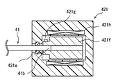
- the fixing part 421 includes a case 421e.
- the fixed end 41b is rotatably received in the case 421e.
- a sleeve 421f as a friction member is fixed to the fixed end 41b.
- Thermowax 421g is provided between the inner surface of the case 421e and the sleeve 421f.
- the thermowax 421g is solid at room temperature or room temperature, and fixes the fixed end 41b.
- the fixing portion 421 includes a heating member 421h that heats the thermowax 421g.
- the heating member 421h can be provided by various devices such as an electric wire for generating Joule heat or a high-frequency coil for electromagnetically generating the sleeve 421f. When the thermowax 421g is heated by the heating member 421h, it liquefies and opens the fixed end 41b.
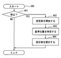
- Step 491 corresponds to step 191.
- Step 492 corresponds to step 192.
- the fixing portions 421 and 422 are controlled to be opened.
- the heating member 421h of the fixing portions 421 and 422 is energized to liquefy the thermowax 421g.
- the actuator element 41 can rotate around the actuator axis AX41.
- Step 493 corresponds to step 193.
- the reference position specifying device 3TZ is excited, and the driven body 31 and the actuator elements 41 and 42 are positioned at the reference position.
- Step 494 corresponds to step 194.
- the fixing units 421 and 422 are controlled to be in a fixed state.
- energization to the heating member 421h is cut off, and the thermowax 421g is solidified.
- the actuator element 41 is fixed with respect to the circumference of the actuator axis AX41.
- the calibration process 490 can be provided by electrical control. Therefore, the calibration process 490 can be automated. Further, the calibration process 490 may be fully automated. For example, in this embodiment, the necessity of the calibration process is instructed by the manual switch 473. Instead, the necessity of the calibration process 490 can be automatically determined. For example, the calibration process 490 may be executed at regular time intervals. Further, the detection signal of the element 32 may be evaluated to determine whether the calibration process 490 is necessary.
- Embodiment which is a modification which makes previous embodiment a basic form is described.
- the fixing portions 421 and 422 are opened and closed in synchronization with the active drive control of the actuator elements 41 and 42.
- the fixing portions 421 and 422 may be controlled to be opened.
- the protection process 590 protects the actuator elements 41 and 42 from excessive deformation due to external force.
- step 595 it is detected whether or not an external force is applied to the driven body 31 or the actuator elements 41 and 42, and it is determined whether or not there is the detected external force. If it is determined in step 595 that there is no external force, the process proceeds to step 596. If it is determined in step 595 that there is an external force, the process proceeds to step 597.
- the driven body 31 has moved in the reverse direction due to the external force, and it is determined that there is an external force. be able to. Further, when an attempt to operate the driven body 31 from the outside is detected, it may be determined that there is an external force. For example, it can be determined that there is an external force when the case housing the movable device 1 is removed.
- step 596 the fixing parts 421 and 422 are controlled to be in a fixed state by closing the fixing parts 421 and 422. Thereby, the fixed end 41b is fixed, and the actuator elements 41 and 42 are provided for normal use.
- step 597 the fixing portions 421 and 422 are opened to control the fixing portions 421 and 422 to be opened. Thereby, the fixed end 41b is opened, and the actuator elements 41 and 42 can freely rotate without being restrained. In the process, the use of the actuator elements 41 and 42 is prohibited by repeating steps 595 and 597. These processes provide a prohibition unit that prohibits the use of the actuator elements 41 and 42.
- the protection process 590 can be executed in addition to the preceding embodiment or the subsequent embodiment, or can be executed only by the protection process 590.
- Embodiment which is a modification which makes previous embodiment a basic form is described.
- two actuator elements 41 and 42 are used.
- only one actuator element 41 may be provided.
- a passive rotation mechanism can be used instead of the second actuator element 42.
- the passive rotation mechanism can be provided by various mechanisms such as rubber, resin spring, metal spring, and air spring.
- a passive rotation mechanism is called a return mechanism.
- the movable device 1 has a return mechanism 622 instead of the second actuator element 42.
- the return mechanism 622 includes a passive elastic member 661, a fixing portion 662, and a fixing portion 663.
- the fixed portion 662 is a block fixed to the base 2.
- the fixing portion 663 is fixed to the driven body 31.
- the elastic member 661 is a metal coil spring.
- the elastic member 661 applies a counterclockwise force to the driven body 31 by being pulled from the free state.
- the elastic member 661 uses one end of the rotation range M631 of the driven body 31 as a reference position.
- the elastic member 661 is arranged to be pulled by the torsional motion of the actuator element 41.
- the elastic member 661 applies a return force against the rotational force in the direction of the arrow M41.
- the second connecting mechanism 21d can adjust the fixing force in order to set the reference position (zero position) of the actuator element 41.
- the second coupling mechanism 21d can be operated with the tool TL.
- the driven body 31 can be positioned at the reference position by the reference position specifying device TZ.
- the operation of setting the reference position can include three stages. First, the fixing portion 21 is opened by loosening the second coupling mechanism 21d with the tool TL. As a result, the fixed end 41b can rotate in the rotation direction. Next, the driven body 31 and the actuator element 41 are positioned at the reference position by the reference position specifying device TZ. Thereby, the position of the fixed end 41b around the actuator axis AX41 is adjusted to the reference position. Finally, the fixing portion 21 is fixed by tightening the second coupling mechanism 21d with the tool TL. At this point, the fixing portion 21 fixes the fixed end 41b. As the fixing part 21, the electric fixing parts 421, 521, and 621 described in the preceding embodiment can be used. Further, the reference position specifying devices 2TZ and 3TZ described in the preceding embodiment can be used as the reference position specifying device TZ.
- the reciprocating motion of the driven body 31 can be obtained by one actuator element 41.
- the guide mechanism 5 since the guide mechanism 5 is provided, the driven body 31 is stabilized.
- the configuration of this embodiment can also be used in other preceding embodiments.
- Embodiment which is a modification which makes previous embodiment a basic form is described.
- the fixing portion is opened for adjustment or protection.
- this embodiment controls the fixed portion to be in an open state even in normal use.
- the movable device 1 includes fixed portions 421 and 422.
- the control device 70 can switch the fixing units 421 and 422 between a fixed state and an open state. Further, the control device 70 executes a control process 780 for swinging the driven body 31.
- the first fixing portion 421 exhibits a fixing force stronger than the fixing force of the second fixing portion 422 when the first actuator element 41 is deformed.
- the second fixing portion 422 exhibits a fixing force stronger than the fixing force of the first fixing portion 421 when the second actuator element 42 is deformed.
- control process 780 includes steps 789a, 789b, 789c, and 789d in addition to the control process 180. Steps 789a, 789b, 789c, and 789d synchronize with the plurality of actuator elements 41, 42, and adjust the fixing force of the fixing portions 421, 422 for them in a complementary manner.
- Step 182 is executed in a state where a part of the first actuator element 41, that is, the fixed end 41b is fixed. Step 182 activates the first actuator element 41. Step 182 provides a first moving step in which the other part of the first actuator element 41, that is, the driven body 31 connected to the output end 41 c is moved by the deformation generated in the first actuator element 41. .
- Step 182 includes Step 789a and Step 789b.
- Step 789 a fixes the fixed end 41 b of the first actuator element 41.
- Step 789b provides a step of releasing a part of the second actuator element 42, that is, the fixed end.
- Step 183 is executed in a state where a part of the second actuator element 42, that is, the fixed end is fixed. Step 183 activates the second actuator element 42. Step 183 provides a second moving step in which the other part of the second actuator element 42, that is, the driven body 31 connected to the output end is moved by deformation generated in the first actuator element 42.
- Step 183 includes Step 789c and Step 789d.
- Step 789c fixes a part of the second actuator element 41.
- Step 789d provides a step of opening a part of the first actuator element 41, that is, the fixed end 41b.
- step 182 the state in step 182 is illustrated.
- the first actuator element 41 is actively driven.
- the second actuator element 42 is opened.
- the second actuator element 42 rotates in the direction of the arrow M41.
- FIG. 18 shows the state in step 183.
- the second actuator element 42 is actively driven.
- the first actuator element 41 is opened.
- the first actuator element 41 rotates in the direction of the arrow M42.
- the load on the complementary actuator elements 41 and 42 can be suppressed.
- a stable amplitude can be realized.
- the other actuator element is invalidated during the movement process by one actuator element.
- the other actuator element may be invalidated only in the initial stage of the movement process by one actuator element, only in the middle period, or only in the latter period.
- the fixing unit may be controlled so that the other actuator element is passively rotated over a predetermined angle. The control method of this embodiment can also be used in the preceding embodiment.
- Embodiment which is a modification which makes previous embodiment a basic form is described.
- fixed part 421,422 uses the thermo wax.
- a magnetorheological fluid whose viscosity can be adjusted by adjusting an electric electromagnetic force is used.
- the fixed end 41b is rotatably received in the case 821e.
- a sleeve 821f as a friction member is fixed to the fixed end 41b.
- a magnetorheological fluid 821g is provided between the inner surface of the case 821e and the sleeve 821f. The magnetorheological fluid 821g behaves as a fluid in a weak magnetic field or zero magnetic field and behaves as a solid in a strong magnetic field.
- the fixing part 421 has an electromagnet 821h.
- the electromagnet 821h applies a magnetic field between the case 821e and the sleeve 821f.
- the magnetorheological fluid 821g behaves as a liquid and opens the fixed end 41b.
- the magnetorheological fluid 821g is placed in a magnetic field by the electromagnet 821h, the case 821e and the sleeve 821f are connected to each other and the fixed end 41b is fixed.
- the electromagnetic clutch of this embodiment can be used as the fixing portions 421 and 422 of the preceding embodiment.
- the electromagnetic clutch of this embodiment is a normally open type that opens the fixed end 41b when not energized, but may be a normally closed type that fixes the fixed end 41b when deenergized.
- Embodiment which is a modification which makes previous embodiment a basic form is described.
- fixed part 421,422 uses the thermo wax.
- this embodiment uses an electromagnetic clutch that can mechanically adjust the fixing force by adjusting the electric electromagnetic force.
- the fixed end 41b is rotatably received in the case 921e.
- a sleeve 921f as a friction member is fixed to the fixed end 41b.
- An armature 921g as a friction member is disposed so as to face the sleeve 921f.
- the armature 921g meshes with the case 921e with respect to the rotation direction.
- the armature 921g is movable along the actuator axis AX41.
- the armature 921g contacts the sleeve 921f and fixes the sleeve 921f and the fixed end 41b.
- the armature 921g is separated from the sleeve 921f and opens the sleeve 921f and the fixed end 41b.
- the fixing part 421 has an electromagnet 921h.
- the electromagnet 921h attracts the armature 921g.
- the armature 921g contacts the sleeve 921f and fixes the fixed end 41b when the electromagnet 921h is not excited.
- the armature 921g moves away from the sleeve 921f and opens the fixed end 41b when the electromagnet 921h is excited.
- the electromagnetic clutch of this embodiment can be used as the fixing portions 421 and 422 of the preceding embodiment.
- the electromagnetic clutch of this embodiment is a normally closed type that fixes the fixed end 41b when not energized, but may be a normally open type that opens the fixed end 41b when deenergized.
- the disclosure in this specification is not limited to the illustrated embodiments.
- the disclosure encompasses the illustrated embodiments and variations by those skilled in the art based thereon.
- the disclosure is not limited to the combinations of parts and / or elements shown in the embodiments.
- the disclosure can be implemented in various combinations.
- the disclosure may have additional parts that can be added to the embodiments.
- the disclosure includes those in which parts and / or elements of the embodiments are omitted.
- the disclosure encompasses the replacement or combination of parts and / or elements between one embodiment and another.
- the technical scope disclosed is not limited to the description of the embodiments.
- the guide mechanism 5 is provided by the shaft 51 and the guide bore 52.
- the shaft 51 and the guide bore 52 provide a so-called bearing mechanism.
- the bearing mechanism that provides the guide mechanism 5 can be provided by many mechanisms such as a ball bearing, a fluid bearing, and a magnetic bearing in addition to the sliding bearing as in the embodiment.
- a relatively simple and lightweight sliding bearing is employed.
- the separate shaft 51 is fixed to the driven body 31.
- the shaft may be formed integrally with the driven body 31 or the support portion 23.
- a cylindrical portion in place of the shaft 51 can be formed on the driven body 31 or the support portion 23 by machining.
- a cylindrical portion instead of the shaft 51 may be insert-molded on the driven body 31 or the support portion 23.
- the movable device 1 includes a guide mechanism 5.
- the driven body 31 may be supported by the actuator elements 41 and 42 and the connection member without providing the guide mechanism 5.
- the winding-shaped connecting member enables the driven body 31 to be stably rotated.
- the guide mechanism 5 includes a shaft 51 and a guide bore 52. Instead, a guide mechanism that suspends the driven body like a pendulum, or a guide mechanism that supports the driven body at a fulcrum like an inverted pendulum may be adopted.
- the control of the actuator elements 41 and 42 and the control of the fixing portions 421 and 422 are synchronized by electrical control.
- the fixing part can be provided with a mechanism for mechanically limiting the rotation direction.
- a ratchet mechanism can be provided in the fixing portion.
- the ratchet mechanism fixes the fixed end 41b.
- the fixed end 41b rotates in the direction of the arrow M41
- the fixed end 41b is opened.
- the ratchet mechanism is in a fixed state to allow active deformation, and is in an open state to negate passive deformation.
- the fixing force by the fixing portions 21, 22, 421, and 422 can be changed between an open state and a fixed state.
- the fixing force may be changed to strength.
- the coupling mechanism 21d may be switched between a state in which it is strongly tightened on the outer peripheral surface of the end sleeve 21a and a state in which it is weakly pressed against the outer peripheral surface of the end sleeve 21a. In this case, the end sleeve 21a rotates while rubbing against the set screw.
- the fixing force by the fixing portions 21 and 421 provided for the fixing end 41b is variable.
- the fixing force at the output end 41c may be variable.
- the coupling mechanism 31a for the output end 41c can be operated.
- an electrically controllable fixing portion 421 may be provided for the output end 41c.
- the heating wire 41d is directly wound around the material wire 41a.
- a member may be disposed between the material wire 41a and the heating wire 41d.
- a support member that is electrically insulating and has excellent thermal conductivity can be disposed.
- the support member can be provided by insulating paper wound around the material wire 41a or a glass tube that accommodates the material wire 41a therein.
- the heating wire 41d is in direct contact with the material wire 41a, but in another embodiment, the heating wire 41d is wound without being in direct contact with the material wire 41a.
- a heat generating member may be disposed on the inner surface of the support member.
- the energy of the material wire 41a is increased or decreased by heating with the heating wire 41d and heat radiation.
- the energy of the material wire 41a can be increased or decreased by cooling with the cooling device and cooling.
- the Peltier effect element can be disposed along the material line 41a. The Peltier effect element provides an energy transfer component. In this case, when the material wire 41a is cooled, the material wire 41a is thermally expanded or contracted to cause torsion deformation.
- a nichrome wire is used as the heating wire 41d.
- the energy transmission component can be provided by various electric heating members.
- the heat generating member may be provided by a conductive thin film called a conductive polymer or a conductive metal film.
- the film is formed on the surface of the material wire 41a.
- the conductive polymer or the conductive metal film is formed on the surface of the material wire 41a by various methods such as plating, synthesis, and sputtering.
- the shape is a spiral wound around the material wire 41a.
- a spiral heat-generating member may be formed by winding a ribbon-like conductive polymer or conductive metal film formed separately from the material wire 41a and disposed outside the material wire 41a.
Landscapes
- Micromachines (AREA)
- Transmission Devices (AREA)
- General Electrical Machinery Utilizing Piezoelectricity, Electrostriction Or Magnetostriction (AREA)
Priority Applications (1)
| Application Number | Priority Date | Filing Date | Title |
|---|---|---|---|
| CN201880018764.XA CN110431304B (zh) | 2017-03-23 | 2018-03-07 | 可动装置及可动装置的控制方法 |
Applications Claiming Priority (2)
| Application Number | Priority Date | Filing Date | Title |
|---|---|---|---|
| JP2017057942A JP2018161010A (ja) | 2017-03-23 | 2017-03-23 | 可動装置、その製造方法、および、その制御方法 |
| JP2017-057942 | 2017-03-23 |
Publications (1)
| Publication Number | Publication Date |
|---|---|
| WO2018173743A1 true WO2018173743A1 (ja) | 2018-09-27 |
Family
ID=63586423
Family Applications (1)
| Application Number | Title | Priority Date | Filing Date |
|---|---|---|---|
| PCT/JP2018/008673 Ceased WO2018173743A1 (ja) | 2017-03-23 | 2018-03-07 | 可動装置、その製造方法、および、その制御方法 |
Country Status (3)
| Country | Link |
|---|---|
| JP (1) | JP2018161010A (https=) |
| CN (1) | CN110431304B (https=) |
| WO (1) | WO2018173743A1 (https=) |
Cited By (2)
| Publication number | Priority date | Publication date | Assignee | Title |
|---|---|---|---|---|
| US11002256B2 (en) | 2017-03-23 | 2021-05-11 | Denso Corporation | Movable device |
| GB2623348A (en) * | 2022-10-13 | 2024-04-17 | Cambridge Mechatronics Ltd | SMA actuator assembly |
Citations (12)
| Publication number | Priority date | Publication date | Assignee | Title |
|---|---|---|---|---|
| JP2003111458A (ja) * | 2001-10-01 | 2003-04-11 | Minolta Co Ltd | 形状記憶合金を用いた駆動装置及び駆動制御方法 |
| JP2007092556A (ja) * | 2005-09-27 | 2007-04-12 | Konica Minolta Opto Inc | 駆動装置及びその製造方法 |
| JP2012227998A (ja) * | 2011-04-15 | 2012-11-15 | Konica Minolta Advanced Layers Inc | 製造方法、および製造装置 |
| JP2013114028A (ja) * | 2011-11-29 | 2013-06-10 | Konica Minolta Advanced Layers Inc | 駆動装置 |
| US20130240320A1 (en) * | 2012-03-15 | 2013-09-19 | GM Global Technology Operations LLC | Active material actuator having a magnetorheological overload protector |
| US20140060036A1 (en) * | 2012-08-31 | 2014-03-06 | GM Global Technology Operations LLC | Compensating for incomplete reversal in mechanisms incorporating shape memory alloy wire |
| JP2015163198A (ja) * | 2010-10-22 | 2015-09-10 | ゴア エンタープライズ ホールディングス,インコーポレイティド | 形状記憶合金作動装置を備えるカテーテル |
| JP2016042783A (ja) * | 2012-08-01 | 2016-03-31 | ザ ボード オブ リージェンツ,ザユニバーシティ オブ テキサス システム | コイル状および非コイル状ナノファイバー撚糸およびポリマーファイバーのねじりおよび引張アクチュエータ |
| WO2016064220A1 (ko) * | 2014-10-22 | 2016-04-28 | 한양대학교 산학협력단 | 온도 변화 또는 온도 구배에 의해 구동되는 회전형 구동기 및 이들을 이용한 에너지 하베스팅 장치 |
| WO2017022146A1 (ja) * | 2015-08-04 | 2017-02-09 | パナソニックIpマネジメント株式会社 | アクチュエータ |
| WO2018047505A1 (ja) * | 2016-09-12 | 2018-03-15 | 株式会社デンソー | アクチュエータ装置 |
| WO2018055972A1 (ja) * | 2016-09-20 | 2018-03-29 | 株式会社デンソー | アクチュエータ装置 |
Family Cites Families (9)
| Publication number | Priority date | Publication date | Assignee | Title |
|---|---|---|---|---|
| US6945045B2 (en) * | 2001-10-01 | 2005-09-20 | Minolta Co., Ltd. | Driving apparatus |
| ATE358787T1 (de) * | 2003-04-17 | 2007-04-15 | Victhom Human Bionics Inc | Auf der technologie der formgedächtnismaterialien basierende bremsvorrichtung mit hohem leistungs- gewichtsverhältnis |
| CN101624974B (zh) * | 2008-09-28 | 2011-01-19 | 哈尔滨工业大学 | 形状记忆合金驱动扭矩输出结构 |
| FR2955404B1 (fr) * | 2010-01-18 | 2012-01-27 | Commissariat Energie Atomique | Actionneur fluidique et dispositif d'affichage a actionneurs fluidiques |
| CN102136391B (zh) * | 2010-01-26 | 2013-09-11 | 厦门市恒源新电力设备有限公司 | 真空接触器电磁机构 |
| CN101839268B (zh) * | 2010-05-27 | 2012-09-05 | 南京晨光集团有限责任公司 | 基于磁控形状记忆合金的数控液压动力单元 |
| JP5533634B2 (ja) * | 2010-12-21 | 2014-06-25 | トヨタ車体株式会社 | 歯車の回転ロック機構 |
| US9638176B2 (en) * | 2013-05-10 | 2017-05-02 | The Boeing Company | Vortex generator using shape memory alloys |
| CN103647369B (zh) * | 2013-12-24 | 2016-05-18 | 北京航空航天大学 | 一种变螺旋形状记忆合金旋转电机 |
-
2017
- 2017-03-23 JP JP2017057942A patent/JP2018161010A/ja active Pending
-
2018
- 2018-03-07 WO PCT/JP2018/008673 patent/WO2018173743A1/ja not_active Ceased
- 2018-03-07 CN CN201880018764.XA patent/CN110431304B/zh not_active Expired - Fee Related
Patent Citations (12)
| Publication number | Priority date | Publication date | Assignee | Title |
|---|---|---|---|---|
| JP2003111458A (ja) * | 2001-10-01 | 2003-04-11 | Minolta Co Ltd | 形状記憶合金を用いた駆動装置及び駆動制御方法 |
| JP2007092556A (ja) * | 2005-09-27 | 2007-04-12 | Konica Minolta Opto Inc | 駆動装置及びその製造方法 |
| JP2015163198A (ja) * | 2010-10-22 | 2015-09-10 | ゴア エンタープライズ ホールディングス,インコーポレイティド | 形状記憶合金作動装置を備えるカテーテル |
| JP2012227998A (ja) * | 2011-04-15 | 2012-11-15 | Konica Minolta Advanced Layers Inc | 製造方法、および製造装置 |
| JP2013114028A (ja) * | 2011-11-29 | 2013-06-10 | Konica Minolta Advanced Layers Inc | 駆動装置 |
| US20130240320A1 (en) * | 2012-03-15 | 2013-09-19 | GM Global Technology Operations LLC | Active material actuator having a magnetorheological overload protector |
| JP2016042783A (ja) * | 2012-08-01 | 2016-03-31 | ザ ボード オブ リージェンツ,ザユニバーシティ オブ テキサス システム | コイル状および非コイル状ナノファイバー撚糸およびポリマーファイバーのねじりおよび引張アクチュエータ |
| US20140060036A1 (en) * | 2012-08-31 | 2014-03-06 | GM Global Technology Operations LLC | Compensating for incomplete reversal in mechanisms incorporating shape memory alloy wire |
| WO2016064220A1 (ko) * | 2014-10-22 | 2016-04-28 | 한양대학교 산학협력단 | 온도 변화 또는 온도 구배에 의해 구동되는 회전형 구동기 및 이들을 이용한 에너지 하베스팅 장치 |
| WO2017022146A1 (ja) * | 2015-08-04 | 2017-02-09 | パナソニックIpマネジメント株式会社 | アクチュエータ |
| WO2018047505A1 (ja) * | 2016-09-12 | 2018-03-15 | 株式会社デンソー | アクチュエータ装置 |
| WO2018055972A1 (ja) * | 2016-09-20 | 2018-03-29 | 株式会社デンソー | アクチュエータ装置 |
Cited By (4)
| Publication number | Priority date | Publication date | Assignee | Title |
|---|---|---|---|---|
| US11002256B2 (en) | 2017-03-23 | 2021-05-11 | Denso Corporation | Movable device |
| GB2623348A (en) * | 2022-10-13 | 2024-04-17 | Cambridge Mechatronics Ltd | SMA actuator assembly |
| WO2024079487A1 (en) * | 2022-10-13 | 2024-04-18 | Cambridge Mechatronics Limited | Sma actuator assembly |
| GB2623348B (en) * | 2022-10-13 | 2025-03-26 | Cambridge Mechatronics Ltd | SMA actuator assembly |
Also Published As
| Publication number | Publication date |
|---|---|
| JP2018161010A (ja) | 2018-10-11 |
| CN110431304A (zh) | 2019-11-08 |
| CN110431304B (zh) | 2021-01-01 |
Similar Documents
| Publication | Publication Date | Title |
|---|---|---|
| US12332444B2 (en) | Variable focus assemblies | |
| JP6714858B2 (ja) | アクチュエータ装置 | |
| WO2018173743A1 (ja) | 可動装置、その製造方法、および、その制御方法 | |
| CN107079090A (zh) | 无人机及摄像组件 | |
| US11025178B2 (en) | Actuator device | |
| WO2018173742A1 (ja) | 可動装置 | |
| WO2018173745A1 (ja) | 可動装置 | |
| WO2018173746A1 (ja) | 可動装置 | |
| EP2546690A1 (en) | Driving mechanism, driving device, and method of manufacturing driving device | |
| WO2018055972A1 (ja) | アクチュエータ装置 | |
| WO2018173744A1 (ja) | 可動装置 | |
| EP4244485A1 (en) | Shape memory alloy actuator architecture for driving adjustable aperture | |
| JP5196582B2 (ja) | 可動鏡機構 | |
| WO2019159754A1 (ja) | アクチュエータ装置 | |
| JP2019146466A (ja) | アクチュエータ装置 | |
| JP2019080439A (ja) | 可動装置 | |
| WO2024098220A1 (zh) | 防抖动机构、摄像头模块、便携终端 | |
| KR101648805B1 (ko) | 압전형 스텝 모터 | |
| JP2006259023A (ja) | レンズ駆動装置 |
Legal Events
| Date | Code | Title | Description |
|---|---|---|---|
| 121 | Ep: the epo has been informed by wipo that ep was designated in this application |
Ref document number: 18772322 Country of ref document: EP Kind code of ref document: A1 |
|
| NENP | Non-entry into the national phase |
Ref country code: DE |
|
| 122 | Ep: pct application non-entry in european phase |
Ref document number: 18772322 Country of ref document: EP Kind code of ref document: A1 |