WO2018173485A1 - Liquid treatment device - Google Patents
Liquid treatment device Download PDFInfo
- Publication number
- WO2018173485A1 WO2018173485A1 PCT/JP2018/002741 JP2018002741W WO2018173485A1 WO 2018173485 A1 WO2018173485 A1 WO 2018173485A1 JP 2018002741 W JP2018002741 W JP 2018002741W WO 2018173485 A1 WO2018173485 A1 WO 2018173485A1
- Authority
- WO
- WIPO (PCT)
- Prior art keywords
- electrode
- liquid
- central axis
- processing apparatus
- plasma
- Prior art date
Links
- 239000007788 liquid Substances 0.000 title claims abstract description 123
- 230000008859 change Effects 0.000 claims description 2
- 230000007246 mechanism Effects 0.000 abstract description 17
- 239000007789 gas Substances 0.000 description 22
- XLYOFNOQVPJJNP-UHFFFAOYSA-N water Substances O XLYOFNOQVPJJNP-UHFFFAOYSA-N 0.000 description 12
- 238000010586 diagram Methods 0.000 description 9
- 230000000694 effects Effects 0.000 description 8
- 230000001954 sterilising effect Effects 0.000 description 7
- 238000000354 decomposition reaction Methods 0.000 description 6
- 239000003344 environmental pollutant Substances 0.000 description 6
- 239000012212 insulator Substances 0.000 description 6
- 231100000719 pollutant Toxicity 0.000 description 6
- 238000002407 reforming Methods 0.000 description 6
- 239000000463 material Substances 0.000 description 5
- 238000000034 method Methods 0.000 description 5
- 230000004048 modification Effects 0.000 description 5
- 238000012986 modification Methods 0.000 description 5
- 238000004659 sterilization and disinfection Methods 0.000 description 5
- 230000004308 accommodation Effects 0.000 description 4
- 230000008569 process Effects 0.000 description 4
- MHAJPDPJQMAIIY-UHFFFAOYSA-N Hydrogen peroxide Chemical compound OO MHAJPDPJQMAIIY-UHFFFAOYSA-N 0.000 description 3
- 239000002101 nanobubble Substances 0.000 description 3
- 241000894006 Bacteria Species 0.000 description 2
- RYGMFSIKBFXOCR-UHFFFAOYSA-N Copper Chemical compound [Cu] RYGMFSIKBFXOCR-UHFFFAOYSA-N 0.000 description 2
- XEEYBQQBJWHFJM-UHFFFAOYSA-N Iron Chemical compound [Fe] XEEYBQQBJWHFJM-UHFFFAOYSA-N 0.000 description 2
- 238000006243 chemical reaction Methods 0.000 description 2
- 239000004020 conductor Substances 0.000 description 2
- 229910052802 copper Inorganic materials 0.000 description 2
- 239000010949 copper Substances 0.000 description 2
- 150000002500 ions Chemical class 0.000 description 2
- 230000001590 oxidative effect Effects 0.000 description 2
- 230000009471 action Effects 0.000 description 1
- QVGXLLKOCUKJST-UHFFFAOYSA-N atomic oxygen Chemical compound [O] QVGXLLKOCUKJST-UHFFFAOYSA-N 0.000 description 1
- 239000000470 constituent Substances 0.000 description 1
- 238000004332 deodorization Methods 0.000 description 1
- 238000007599 discharging Methods 0.000 description 1
- 230000007613 environmental effect Effects 0.000 description 1
- QOSATHPSBFQAML-UHFFFAOYSA-N hydrogen peroxide;hydrate Chemical compound O.OO QOSATHPSBFQAML-UHFFFAOYSA-N 0.000 description 1
- 238000003780 insertion Methods 0.000 description 1
- 230000037431 insertion Effects 0.000 description 1
- 229910052742 iron Inorganic materials 0.000 description 1
- 229910052751 metal Inorganic materials 0.000 description 1
- 239000002184 metal Substances 0.000 description 1
- 150000002894 organic compounds Chemical class 0.000 description 1
- 239000001301 oxygen Substances 0.000 description 1
- 229910052760 oxygen Inorganic materials 0.000 description 1
- 239000012466 permeate Substances 0.000 description 1
- 238000009832 plasma treatment Methods 0.000 description 1
- 230000005855 radiation Effects 0.000 description 1
- WFKWXMTUELFFGS-UHFFFAOYSA-N tungsten Chemical compound [W] WFKWXMTUELFFGS-UHFFFAOYSA-N 0.000 description 1
- 229910052721 tungsten Inorganic materials 0.000 description 1
- 239000010937 tungsten Substances 0.000 description 1
Images


Classifications
-
- C—CHEMISTRY; METALLURGY
- C02—TREATMENT OF WATER, WASTE WATER, SEWAGE, OR SLUDGE
- C02F—TREATMENT OF WATER, WASTE WATER, SEWAGE, OR SLUDGE
- C02F1/00—Treatment of water, waste water, or sewage
- C02F1/46—Treatment of water, waste water, or sewage by electrochemical methods
- C02F1/4608—Treatment of water, waste water, or sewage by electrochemical methods using electrical discharges
-
- C—CHEMISTRY; METALLURGY
- C02—TREATMENT OF WATER, WASTE WATER, SEWAGE, OR SLUDGE
- C02F—TREATMENT OF WATER, WASTE WATER, SEWAGE, OR SLUDGE
- C02F1/00—Treatment of water, waste water, or sewage
- C02F1/008—Control or steering systems not provided for elsewhere in subclass C02F
-
- C—CHEMISTRY; METALLURGY
- C02—TREATMENT OF WATER, WASTE WATER, SEWAGE, OR SLUDGE
- C02F—TREATMENT OF WATER, WASTE WATER, SEWAGE, OR SLUDGE
- C02F1/00—Treatment of water, waste water, or sewage
- C02F1/30—Treatment of water, waste water, or sewage by irradiation
- C02F1/32—Treatment of water, waste water, or sewage by irradiation with ultraviolet light
-
- C—CHEMISTRY; METALLURGY
- C02—TREATMENT OF WATER, WASTE WATER, SEWAGE, OR SLUDGE
- C02F—TREATMENT OF WATER, WASTE WATER, SEWAGE, OR SLUDGE
- C02F1/00—Treatment of water, waste water, or sewage
- C02F1/46—Treatment of water, waste water, or sewage by electrochemical methods
- C02F1/461—Treatment of water, waste water, or sewage by electrochemical methods by electrolysis
- C02F1/46104—Devices therefor; Their operating or servicing
- C02F1/46109—Electrodes
- C02F2001/46123—Movable electrodes
-
- C—CHEMISTRY; METALLURGY
- C02—TREATMENT OF WATER, WASTE WATER, SEWAGE, OR SLUDGE
- C02F—TREATMENT OF WATER, WASTE WATER, SEWAGE, OR SLUDGE
- C02F1/00—Treatment of water, waste water, or sewage
- C02F1/46—Treatment of water, waste water, or sewage by electrochemical methods
- C02F1/461—Treatment of water, waste water, or sewage by electrochemical methods by electrolysis
- C02F1/46104—Devices therefor; Their operating or servicing
- C02F1/46109—Electrodes
- C02F2001/46152—Electrodes characterised by the shape or form
- C02F2001/46171—Cylindrical or tubular shaped
-
- C—CHEMISTRY; METALLURGY
- C02—TREATMENT OF WATER, WASTE WATER, SEWAGE, OR SLUDGE
- C02F—TREATMENT OF WATER, WASTE WATER, SEWAGE, OR SLUDGE
- C02F2201/00—Apparatus for treatment of water, waste water or sewage
- C02F2201/46—Apparatus for electrochemical processes
- C02F2201/461—Electrolysis apparatus
- C02F2201/46105—Details relating to the electrolytic devices
- C02F2201/4612—Controlling or monitoring
- C02F2201/46125—Electrical variables
- C02F2201/4614—Current
-
- C—CHEMISTRY; METALLURGY
- C02—TREATMENT OF WATER, WASTE WATER, SEWAGE, OR SLUDGE
- C02F—TREATMENT OF WATER, WASTE WATER, SEWAGE, OR SLUDGE
- C02F2301/00—General aspects of water treatment
- C02F2301/02—Fluid flow conditions
- C02F2301/026—Spiral, helicoidal, radial
-
- C—CHEMISTRY; METALLURGY
- C02—TREATMENT OF WATER, WASTE WATER, SEWAGE, OR SLUDGE
- C02F—TREATMENT OF WATER, WASTE WATER, SEWAGE, OR SLUDGE
- C02F2303/00—Specific treatment goals
- C02F2303/04—Disinfection
Definitions
- the present disclosure relates to a liquid processing apparatus for electrochemically processing a liquid. More specifically, the present disclosure relates to a decomposition and sterilization effect caused by direct contact of plasma with pollutants or bacteria contained in the liquid by generating plasma in the liquid, and decomposition and ultraviolet radiation generated by plasma discharge.
- the present invention relates to a liquid processing apparatus for processing liquid by causing a sterilizing action simultaneously.
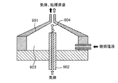
- FIG. 13 shows an example of a conventional liquid processing apparatus.
- the first electrode 801 and the second electrode 802 are disposed in the liquid 803 (for example, water), and a high voltage pulse is applied between the first electrode 801 and the second electrode 802 from the pulse power source 804 to thereby form the liquid 803. Is vaporized to generate plasma 805.
- the pollutant contained in the liquid 803 is decomposed by direct contact with the plasma 805.
- components having oxidizing power such as hydroxyl radicals (OH radicals) or hydrogen peroxide are generated, and the decomposition process proceeds by reacting these components with the pollutant contained in the liquid 803.
- OH radicals are known to have a high oxidizing power, and decompose a hardly decomposable organic compound dissolved in liquid 803. Is possible.
- a liquid processing apparatus in which a gas introduced from the outside is interposed between both electrodes (see Patent Document 1).
- a gas 904 for example, oxygen
- a pulse voltage is applied between the electrode 902 and the electrode 902.
- plasma is generated in the gas 904, and the decomposition treatment of the liquid to be processed 903 progresses at the contact surface between the plasma and the liquid to be processed 903.
- the applied voltage can be reduced as compared with the case where no gas is interposed, and the liquid can be processed by generating plasma efficiently.
- one end along the central axis is closed and the cross-sectional shape orthogonal to the central axis is circular, and the circular cross-sectional shape is formed on the one end side of the central axis.
- a cylindrical treatment tank having a liquid introduction port for turning the liquid around the central axis by introducing the liquid from the tangential direction of the liquid and generating a gas phase in the swirling flow of the liquid, and the treatment tank A rod-shaped first electrode disposed on the one end side of the central axis, a second electrode disposed on the other end side of the central axis of the processing tank, and between the first electrode and the second electrode A power source for applying a voltage to the first electrode, and an electrode rotating device for rotating the first electrode around a central axis of the first electrode.
- the tip end of the first electrode is averagely worn around the central axis by rotating the first electrode around the central axis of the first electrode by the electrode rotating device.
- the plasma can be stabilized, the plasma can be generated efficiently, the liquid can be processed quickly, the plasma can be generated stably for a long time, and the equipment can be operated for a long time.
- the liquid is vaporized in a swirling flow, and plasma is generated by applying a pulse voltage to the generated gas phase. Since it is not necessary to vaporize the liquid by applying a voltage, plasma can be generated with a small amount of power, and the liquid can be processed efficiently and quickly.
- FIG. 1 is a side cross-sectional view illustrating a configuration of a liquid processing apparatus according to Embodiment 1 of the present disclosure.
- FIG. 2 is a side sectional view of the apparatus main body.
- FIG. 3 is a cross-sectional view taken along line 3-3 in FIG.
- FIG. 4 is a side cross-sectional view showing a state where a swirling flow is generated inside the processing tank and no voltage is applied.
- FIG. 5A is a side cross-sectional view showing a state in which a swirling flow is generated inside the processing tank and a voltage is applied.
- FIG. 5B is a partially enlarged view of a state in which plasma is generated in the gas phase of FIG. 5A.
- FIG. 6 is a diagram illustrating how the wear of the first electrode progresses.
- FIG. 7 is a diagram illustrating an effect of preventing the first electrode from being biased and worn by the rotation mechanism.
- FIG. 8 is a diagram illustrating a difference in wear shape of the first electrode due to a difference in rotation angle and rotation interval of the rotation mechanism.
- FIG. 9 is a diagram showing a processing tank in which cylinders having different radii are combined.
- FIG. 10 is a diagram showing a conical treatment tank.
- FIG. 11 is a side sectional view showing a modification of the apparatus main body.
- FIG. 12A is a current waveform diagram when the plasma measured by the ammeter emits light.
- FIG. 12B is a side cross-sectional view in which a copper material is disposed in a part of the storage tank in a modification of the apparatus main body.
- FIG. 13 is a cross-sectional view of a conventional liquid processing apparatus.
- FIG. 14 is a cross-sectional view of a conventional liquid processing apparatus including a gas introduction device.
- a rod-shaped electrode is used as one electrode.
- the rod-shaped electrode is slightly inclined with respect to the discharge direction or attached with a slight eccentricity, so that when the plasma is generated between the electrodes for a long time, the tip of the rod-shaped electrode is biased. It will wear out. If the bias of the tip due to wear becomes large, plasma cannot be stably generated in the end, and thus there is a problem that the equipment cannot be operated for a long time.
- the present disclosure aims to provide a liquid processing apparatus capable of generating plasma efficiently and processing liquid quickly and stably generating plasma for a long time. .
- FIG. 1 is a side cross-sectional view illustrating a configuration of a liquid processing apparatus 100 according to Embodiment 1 of the present disclosure.
- the arrow F indicates the forward direction of the liquid processing apparatus 100
- the arrow B indicates the backward direction.
- Arrow U indicates the upward direction
- arrow D indicates the downward direction.
- the arrow R indicates the right direction when viewed from the rear direction
- the arrow L indicates the left direction when viewed from the rear direction.
- the liquid processing apparatus 100 processes a liquid by discharging in the liquid.
- a liquid L1 in which a pollutant is dissolved is processed as an example of a liquid to be processed will be described.
- the processing liquid processed by the liquid processing apparatus 100 is stored.
- the liquid processing apparatus 100 functions as at least an example of a processing tank 12 having an introduction unit 15 that functions as an example of a liquid introduction port, a first electrode 30, a second electrode 31, a power source 60, and an electrode rotation device. And a rotation mechanism 200. More specifically, the liquid processing apparatus 100 includes an apparatus main body 10, a liquid supply unit 50, and a power supply 60.
- the apparatus main body 10 includes a processing tank 12, an introduction unit 15, a discharge unit 17, a first electrode 30, and a second electrode 31.
- the processing tank 12 is a cylindrical tank that is processing the liquid (for example, water) L1 introduced into the inside.
- the front sectional shape of the treatment tank 12 is circular (see FIG. 3).
- the introduction part 15 is disposed on one end side of the central axis X ⁇ b> 1 of the processing tank 12 that is closed, and the liquid L ⁇ b> 1 is supplied to the processing tank 12, for example, a tangential direction with a circular cross-sectional shape orthogonal to the central axis X ⁇ b> 1 of the processing tank 12. Introduce from.
- the introduction unit 15 communicates with the liquid supply unit 50 via the pipe 51.
- the discharge part 17 is arrange
- the discharge unit 17 is disposed on the other end side of the central axis X ⁇ b> 1 of the processing tank 12 and is connected to the intake port 91 of the storage tank 90.
- the processing liquid L2 discharged from the discharge unit 17 is stored in the storage tank 90.
- the first electrode 30 is a rod-shaped electrode in which at least an inner end portion is disposed inside one end of the treatment tank 12. As an example, the first electrode 30 is disposed so as to protrude from the center of the inner wall of one end of the processing tank 12 into the processing tank 12 along the longitudinal direction, for example, along the central axis X1.
- the material of the first electrode 30 is, for example, tungsten.
- the second electrode 31 is disposed outside the wall at the other end of the treatment tank 12 and is disposed in the vicinity of the discharge unit 17.
- the first electrode 30 is connected to a power source 60, and the second electrode 31 is grounded.
- a high voltage pulse voltage is applied to the first electrode 30 and the second electrode 31 by the power supply 60.
- Liquid supply part 50 is a pump which supplies liquid (for example, water) L1 in processing tank 12 as an example.
- the liquid supply unit 50 is connected to the pipe 51.
- One end of the pipe 51 is connected to an introduction portion 15 as an inner opening disposed in the vicinity of the inner wall of one end of the treatment tank 12, and the other end of the pipe 51 is a liquid supply source (for example, a water tank 80) (not shown) or It connects so that the stored water containing the processing liquid of the storage tank 90 can be circulated (refer the piping 81 for circulation of the dashed-dotted line of FIG. 1).
- the power source 60 applies a high voltage pulse voltage between the first electrode 30 and the second electrode 31.
- the power supply 60 can apply a so-called bipolar pulse voltage that alternately applies a positive pulse voltage and a negative pulse voltage.
- the rotation mechanism 200 is attached to the first electrode 30 and can rotate the first electrode 30 around the central axis 30c of the first electrode 30 (see FIG. 7) with respect to the processing bath 12.
- the rotation mechanism 200 includes a motor that can hold the first electrode 30 and can control the rotation angle. If necessary, for example, under the control of the control device 230, the first electrode 30 can be rotated by the rotation mechanism 200 by a predetermined angle at a predetermined time or a predetermined time interval after the power is turned on.
- the rotation mechanism 200 is driven and controlled by the control device 230, and under the control of the control device 230, the first electrode 30 is moved by the rotation mechanism 200 at a predetermined angle or a predetermined time from the voltage application by the power supply 60. It is possible to rotate.
- the storage tank 90 shears a treatment liquid discharged from the liquid processing apparatus 100, that is, a reforming component such as OH radicals, generates microbubbles or nanobubbles containing the reforming component, and generates a treatment liquid (for example, water).
- a reforming component such as OH radicals
- the storage tank 90 has a cross-sectional area larger than the opening cross-sectional area of the discharge part 17 of the treatment tank 12 inside, and stores the reforming components discharged from the discharge part 17 into the storage tank 90.
- Microbubbles containing the modified component, or microbubbles and nanobubbles are generated in the storage tank 90 and are diffused into water to generate a treatment liquid. Therefore, the storage tank 90 functions as a microbubble generation tank.
- As the storage tank 90 at least an inner diameter or one side that is twice or more the inner diameter dimension of the opening of the discharge portion 17 of the processing tank 12 can be secured, and a processing liquid that can surely sterilize can be generated in the storage tank 90. .
- FIG. 2 is a side sectional view of the apparatus main body 10.
- the treatment tank 12 has a first inner wall 21, a second inner wall 22, and a third inner wall 23.
- the material of the treatment tank 12 may be an insulator or a conductor. In the case of a conductor, it is necessary to interpose an insulator between the first electrode 30 and the second electrode 31.
- the first inner wall 21 is a cylindrical wall portion.
- the second inner wall 22 is provided at the left end portion of the first inner wall 21 in FIG.
- the third inner wall 23 is provided at the right end of the first inner wall 21 in FIG.
- the second inner wall 22 and the third inner wall 23 are substantially circular in a side view.
- the first inner wall 21, the second inner wall 22, and the third inner wall 23 constitute a substantially cylindrical accommodation space 83 inside the processing tank 12.
- the central axis of the first inner wall 21, that is, the virtual central axis of the substantially cylindrical accommodation space 83 configured inside the processing tank 12 is defined as a central axis X ⁇ b> 1.
- the second inner wall 22 is provided with a cylindrical electrode support cylinder 24 projecting into the accommodation space 83 at the center.
- the electrode support cylinder 24 is cylindrical and extends rightward.
- the electrode support cylinder 24 is arranged so that its central axis coincides with the central axis X1.
- the first electrode 30 is supported inside the electrode support cylinder 24 via an insulator 53.
- the first electrode 30 has a rod shape, and the insulator 53 is disposed around the first electrode 30. For this reason, the first electrode 30 is disposed such that the longitudinal axis thereof coincides with the central axis X1.
- the inner end surface of the right end portion 301 of the first electrode 30 protrudes into the accommodation space 83 from the inner end surface of the insulator 53, and the inner end surface 241 of the electrode support tube 24 extends from the inner end surface of the right end portion 301 of the first electrode 30. It is comprised so that it may protrude inside.
- the rotation mechanism 200 is attached to the first electrode 30 outside the processing tank 12, and the first electrode 30 is disposed at a predetermined time or a predetermined time interval with respect to the processing tank 12 around the central axis 30 c of the first electrode 30. Can be rotated by a predetermined angle.
- the central axis 30c of the first electrode 30 may be the same as or different from the central axis X1.
- the introduction part 15 penetrates the apparatus main body 10, and one open end 151 is formed on the first inner wall 21.
- the introduction portion 15 is disposed at a position adjacent to the second inner wall 22 in a side view.
- FIG. 3 is a cross-sectional view taken along line 3-3 in FIG.
- the introduction part 15 is disposed on the wall surface of the first inner wall 21.
- the discharge part 17 penetrates the central part of the third inner wall 23.
- the discharge portion 17 is formed so that its central axis coincides with the central axis X1.
- the second electrode 31 is a plate-like metal member, and an opening 311 is formed at the center.
- the opening 311 is circular, and is formed so that its central axis coincides with the central axis X1.
- FIG. 4 is a side cross-sectional view showing a state in which a swirling flow F1 is generated inside the processing tank 12 and no pulse voltage is applied.
- the pressure in the vicinity of the central axis X1 is reduced to the saturated water vapor pressure or less, and a part of the liquid L1 is vaporized to generate the gas phase G in the vicinity of the central axis X1.
- the gas phase G is generated near the turning center, specifically, from the right end 301 of the first electrode 30 to the vicinity of the opening 311 of the second electrode 31 along the central axis X1.
- the gas phase G is swirled in the same direction as the swirling flow F1 by the swirling flow F1 in contact therewith.
- the gas phase G receives the resistance of the liquid in the storage tank 90 in the vicinity of the discharge unit 17, so that it is sheared into microbubbles or microbubbles and nanobubbles and diffused into the liquid in the storage tank 90.
- FIG. 5A is a side sectional view showing a state in which a swirling flow F1 is generated inside the processing tank 12 and a pulse voltage is applied.
- FIG. 5B is an enlarged view showing a state where the plasma P is generated in the gas phase G.
- the power source 60 and the first electrode 30 A high voltage pulse voltage is applied between the two electrodes 31.
- the first electrode 30 and the second electrode 31 generate plasma P in the gas phase G (see FIG. 5B), and generate radicals (OH radicals or the like) or ions. .
- the radicals or ions are dissolved from the gas phase G to the swirl flow F1 side to decompose the pollutant dissolved in the solution.
- the plasma P in the gas phase G in the vicinity of the discharge unit 17 generates a large amount of bubbles BA containing OH radicals and the like due to the resistance of the liquid in the storage tank 90.
- the treatment liquid L ⁇ b> 2 that is treated with OH radicals generated by the plasma P and contains bubbles BA containing OH radicals and the like is discharged from the discharge unit 17 toward the storage tank 90.
- the plasma P can be generated efficiently and the liquid L1 can be processed quickly.
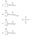
- FIG. 6 is a diagram illustrating how the wear of the first electrode 30 progresses.
- FIG. 6A shows an initial stage before plasma is generated. From this state, when the plasma L is generated and the liquid L1 is processed, the first electrode 30 is worn unevenly as shown in FIG. 6B, and the tip 30a becomes sharp. If the plasma P continues to be generated as it is, the bias becomes larger as shown in FIG. 6C, and finally the first electrode 30 is significantly biased as shown in FIG. 6D. As a result of wear, the gas phase G is also decentered and plasma generation becomes unstable.
- the first electrode 30 can be rotated by a predetermined angle around the central axis 30c of the first electrode 30 by a predetermined angle by the rotation mechanism 200. It is valid.
- FIG. 7 is a diagram illustrating an effect of preventing the first electrode 30 from being unevenly worn by rotating the first electrode 30 by the rotation mechanism 200.
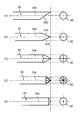
- FIG. 8 is a diagram illustrating a difference in the wear shape of the first electrode 30 due to a difference in rotation angle and rotation interval of the rotation mechanism 200.
- the total time during which the plasma P is generated is the same, and the rotation operation is performed at regular intervals.
- FIG. 8A shows a case where the first electrode 30 is not rotated
- FIG. 8B shows a case where 180 ° rotation is performed once
- FIG. 8C shows 90 ° rotation.
- 8 (d) shows the case where the 45 degree rotation is performed 7 times. In other words, FIG. 8 (e) always generates the plasma P while continuously rotating. Shows the case.
- FIG. 8 shows a case where the first electrode 30 is not rotated
- FIG. 8B shows a case where 180 ° rotation is performed once
- FIG. 8C shows 90 ° rotation.
- 8 (d) shows the case where the 45 degree rotation is performed 7 times.
- FIG. 8 (e) always generates the plasma P while continuously rotating. Shows the case.
- FIG. 8 shows
- FIG. 8 (a) only one side of the tip 30a of the rod electrode that is the first electrode 30 has been worn, but in FIG. 8 (b), both sides of the rod electrode are worn and the tip is It has a wedge shape.
- FIG. 8C in which the 90 ° rotation is performed three times, the four surfaces are worn and the sharpness of the tip is reduced.
- FIG. 8D the rotation angle is 45 degrees, and the sharpness of the tip is further reduced.
- FIG. 8E shows a case where the tip is always rotated (for example, during the plasma generation period), and the tip is sharpest and the tip shape is conical.
- the tip portion 30a of the first electrode 30 is averaged around the central axis 30c.
- the plasma P is stabilized, the plasma P is generated efficiently, the liquid L1 can be processed quickly, and the plasma P can be generated stably for a long time. It can be operated. That is, the phenomenon in which the first electrode 30 is slightly worn from the central axis X1 or is eccentrically attached and caused by the generation of plasma over a long period of time causes the first electrode 30 to be centered on the first electrode 30. It can be suppressed by rotating around the axis 30c, and the plasma P can be generated stably for a long time.
- the liquid L1 is vaporized in the swirling flow F1, and a pulse voltage is applied to the generated gas phase G to generate the plasma P. Therefore, the plasma P is generated efficiently.
- the liquid L1 can be processed quickly.
- the treatment tank 12 has a simple cylindrical shape.
- one end portion of the central axis X1 is a cylindrical treatment tank having a closed cross-section
- the shape is various. It is possible to take.
- the same effect can be obtained even in a processing tank 121 in which cylinders having different radii are combined.
- the radius of the cross-sectional area on the liquid introduction part side in the processing tank 121 is configured to be larger than the radius of the cross-sectional area on the liquid discharge part side.
- the same effect is acquired even if it is the cone-shaped process tank 122 shown in FIG.
- the swirling flow F1 from sliding in the forward direction F, as shown in FIG.
- the first electrode 30 was only rotated by the rotation mechanism 200.
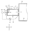
- an electrode moving device 210, an ammeter 220, and a control device 230 are provided. Further, the distance between the first electrode 30 and the second electrode 31 may be adjustable.
- the ammeter 220 is connected between the first electrode 30 and the second electrode 31.
- the electrode moving device 210 changes the distance between the first electrode 30 and the second electrode 31 based on the current value measured by the ammeter 220. More specifically, the electrode moving device 210 includes, for example, a motor 211, a ball screw 212 that is coupled to the motor 211 and is driven to rotate forward and backward, and is screwed to the ball screw 212 and holds the first electrode 30. And a movable body 213 capable of moving back and forth in the axial direction of the first electrode 30. Therefore, when the control device 230 drives and controls the motor 211 based on the current value measured by the ammeter 220, the ball screw 212 rotates forward and backward, and the movable body 213 moves back and forth, so that the first electrode 30 can be taken in and out of the treatment tank 12.
- the control device 230 determines that the current waveform output from the ammeter 220 has changed from the initial state, this state means that the first electrode 30 is worn. For this reason, the control device 230 gives a control command to the electrode moving device 210, and the electrode moving device 210 inserts the first electrode 30 into the treatment tank 12, so that the first electrode 30 and the second electrode 31 are inserted. To control the distance.
- the insertion amount of the first electrode 30 is determined by previously obtaining the relationship between the state of change of the current waveform output from the ammeter 220 from the initial state and the wear state of the first electrode 30.
- the movement distance of the first electrode 30 to be inserted into the treatment tank 12 is also determined in advance corresponding to the state.
- the electrode moving device 210 can be driven and controlled so that the first electrode 30 can be inserted into the processing tank 12 by the moving distance of the first electrode 30.
- the distance between the first electrode 30 and the second electrode 31 can be maintained constant without directly measuring the distance between the first electrode 30 and the second electrode 31. It is possible to stabilize the plasma generation.
- control device 230 sets a determination threshold value as a current value output from the ammeter 220 that is equal to or less than the peak current value when the plasma emits light and equal to or more than the peak current value when the plasma does not emit light. By setting in this way, if the control device 230 determines that the current value output from the ammeter 220 is within the determination threshold, it means that the plasma is emitted. It can be easily determined by the control device 230. Further, the control device 230 can determine that the rate exceeding the determination threshold per unit time is the plasma generation rate.
- the control device 230 determines that the ratio exceeding the determination threshold per unit time is equal to or less than the desired ratio, the control device 230 drives the electrode moving device 210 to connect the first electrode 30 to the second electrode 31.
- the distance between the first electrode 30 and the second electrode 31 can be controlled to be constant.
- a desired plasma generation rate can be achieved by a simple method without directly measuring the distance between the first electrode 30 and the second electrode 31, and the plasma generation can be stabilized.
- the control device 230 can determine that the wear state shown in FIG.
- the control device 230 gives a control command to the electrode moving device 210 and sets the distance between the first electrode 30 and the second electrode 31. Control.
- the peak current value when plasma is emitted can be set to a state after the electrode distance in FIG. 12A (c) is controlled to be constant.
- the control for making the electrode distance constant by the control device 230 is stopped.
- a plate member 92 containing copper or iron that can cause a Fenton reaction with hydrogen peroxide water, which is one of the reforming components, to exhibit a high sterilization effect is stored in the storage tank 90.
- the plate member 92 may be disposed in the storage tank 90 as a separate member from the storage tank 90. In short, when the plate member 92 comes into contact with the reforming liquid in the storage tank 90, a high sterilizing effect can be exhibited by causing a Fenton reaction with hydrogen peroxide solution which is one of the reforming components.
- the configuration of the liquid processing apparatus 100 described in the first embodiment is an example, and various changes can be made.
- the internal structure of the processing tank 12 or the position of the first electrode 30 or the second electrode 31 is not limited to the structure of the first embodiment.
- the first electrode 30 is arranged on the closed end side of the cylindrical treatment tank 12 and the second electrode 31 is arranged in the vicinity of the discharge unit 17, but they are arranged opposite to each other. Even if it is, the same effect is acquired.
- Embodiment 1 of this indication was explained, Embodiment 1 mentioned above is only an illustration for carrying out this indication. Therefore, the present disclosure is not limited to the above-described first embodiment, and can be implemented by appropriately modifying the above-described first embodiment without departing from the spirit of the present disclosure.
- the liquid processing apparatus can maintain the distance between the two electrodes constant by rotating the electrode, the liquid can be generated efficiently and the liquid can be processed quickly. It can be generated stably for a long time. Therefore, the liquid processing apparatus according to the aspect of the present disclosure generates plasma in the liquid, thereby generating a decomposition and sterilization action caused by direct contact of the pollutant or bacteria contained in the liquid with the plasma, and plasma discharge.
- the liquid can be treated by causing simultaneous decomposition and sterilization by ultraviolet rays or radicals. For this reason, this processing liquid can be used for sterilization, deodorization, various environmental improvements, and the like.
- SYMBOLS 100 Liquid processing apparatus 10 Apparatus main body 12 Processing tank 121 Processing tank 122 Processing tank 15 Introduction part (liquid inlet) 17 discharge part 21 1st inner wall 22 2nd inner wall 23 3rd inner wall 24 Electrode support cylinder 30 1st electrode 30a Tip part 30b Lower side of tip part 30c Center axis (center axis of 1st electrode) 30d Reverse side of tip 31 Second electrode 50 Liquid supply part 51 Pipe 53 Insulator 60 Power supply 80 Water tank 81 Dotted line (circulation pipe) 83 Storage space 90 Storage tank 151 Open end 200 Rotating mechanism (electrode rotating device) DESCRIPTION OF SYMBOLS 210 Electrode moving apparatus 211 Motor 212 Ball screw 213 Movable body 220 Ammeter 230 Controller 241 Inner end surface 301 Right end 311 Opening 801 First electrode 802 Second electrode 803 Liquid 804 Pulse power source 805 Plasma 901 Anode electrode 902 Cathode electrode 903 Treatment liquid 904 Gas BA
Abstract
This liquid treatment device is provided with: a cylindrical treatment tank that has a closed end along the center axis and in which the cross-sectional shape orthogonal to the center axis is circular; a first electrode that has a bar shape and that is disposed at one end of the center axis of the treatment tank; a second electrode disposed at the other end of the center axis of the treatment tank; a power supply for applying a voltage between the first and second electrodes; and a rotation mechanism for rotating the first electrode about the center axis of the first electrode, wherein, at one end of the center axis of the treatment tank, an introduction part for introducing a liquid from the tangential direction of the circular cross-sectional shape of the treatment tank so that the liquid is turned in the treatment tank about the center axis of the treatment tank, and for generating a gas phase in the turning flow of the liquid, is provided.
Description
本開示は、液体を電気化学的に処理する液体処理装置に関する。より詳細には、本開示は、液体中でプラズマを発生させ、液体に含まれる汚濁物質又は菌がプラズマに直接触れることによる分解及び殺菌作用と、プラズマ放電により発生する紫外線又はラジカルなどによる分解及び殺菌作用を同時に起こして、液体を処理する液体処理装置に関する。
The present disclosure relates to a liquid processing apparatus for electrochemically processing a liquid. More specifically, the present disclosure relates to a decomposition and sterilization effect caused by direct contact of plasma with pollutants or bacteria contained in the liquid by generating plasma in the liquid, and decomposition and ultraviolet radiation generated by plasma discharge. The present invention relates to a liquid processing apparatus for processing liquid by causing a sterilizing action simultaneously.
図13に、従来の液体処理装置の例を示す。液体803(例えば、水)の中に、第1電極801及び第2電極802を配置し、パルス電源804から第1電極801と第2電極802との間に高電圧パルスを印加して液体803を気化させ、プラズマ805を発生させる。このとき、プラズマ805が直接触れることで、液体803中に含まれる汚濁物質等が分解処理される。同時に、例えば、ヒドロキシルラジカル(OHラジカル)又は過酸化水素等の酸化力を持つ成分が生成され、それらの成分が液体803中に含まれる汚濁物質等と反応することでも分解処理が進展する。水中にプラズマ805が発生することにより生成されるラジカルの中でも、特にOHラジカルは高い酸化力を有することが知られており、液体803中に溶解している難分解性有機化合物を分解処理することが可能である。
FIG. 13 shows an example of a conventional liquid processing apparatus. The first electrode 801 and the second electrode 802 are disposed in the liquid 803 (for example, water), and a high voltage pulse is applied between the first electrode 801 and the second electrode 802 from the pulse power source 804 to thereby form the liquid 803. Is vaporized to generate plasma 805. At this time, the pollutant contained in the liquid 803 is decomposed by direct contact with the plasma 805. At the same time, for example, components having oxidizing power such as hydroxyl radicals (OH radicals) or hydrogen peroxide are generated, and the decomposition process proceeds by reacting these components with the pollutant contained in the liquid 803. Among radicals generated by the generation of plasma 805 in water, especially OH radicals are known to have a high oxidizing power, and decompose a hardly decomposable organic compound dissolved in liquid 803. Is possible.
しかしながら、上記従来の液体処理装置の場合、液体803を気化させるために高い印加電圧が必要なだけでなく、プラズマ805の発生効率が低く、液体803を処理するのに長時間を要するという問題があった。
However, in the case of the above conventional liquid processing apparatus, not only a high applied voltage is required to vaporize the liquid 803, but also the generation efficiency of the plasma 805 is low and it takes a long time to process the liquid 803. there were.
そこで、印加電圧を低くしつつプラズマの発生効率を向上させるために、両電極間に外部より導入した気体を介在させるようにした液体処理装置が知られている(特許文献1参照)。特許文献1に記載の液体処理装置(図14)では、アノード電極901とカソード電極902との間に被処理液903とともに気体904(例えば、酸素)を介在させた上で、アノード電極901とカソード電極902との間にパルス電圧を印加する。パルス電圧の印加により、気体904内にプラズマが発生し、プラズマと被処理液903との接触面で被処理液903の分解処理が進展する。特許文献1に記載の液体処理によれば、気体を介在させない場合よりも印加電圧を低減させることができ、かつ、プラズマを効率良く発生させて液体の処理を行うことができる。
Therefore, in order to improve the plasma generation efficiency while lowering the applied voltage, a liquid processing apparatus is known in which a gas introduced from the outside is interposed between both electrodes (see Patent Document 1). In the liquid processing apparatus described in Patent Document 1 (FIG. 14), a gas 904 (for example, oxygen) is interposed between the anode electrode 901 and the cathode electrode 902 together with the liquid 903 to be processed, and then the anode electrode 901 and the cathode. A pulse voltage is applied between the electrode 902 and the electrode 902. By applying the pulse voltage, plasma is generated in the gas 904, and the decomposition treatment of the liquid to be processed 903 progresses at the contact surface between the plasma and the liquid to be processed 903. According to the liquid treatment described in Patent Document 1, the applied voltage can be reduced as compared with the case where no gas is interposed, and the liquid can be processed by generating plasma efficiently.
本開示の1つの態様にかかる液体処理装置は、中心軸沿いの一端が閉口しかつ前記中心軸と直交する断面形状が円形であるとともに、前記中心軸の前記一端側に、前記円形の断面形状の接線方向から液体を導入することにより前記液体を前記中心軸周りに旋回させ、前記液体の旋回流中に気相を発生させる液体導入口を有する筒状の処理槽と、前記処理槽の前記中心軸の前記一端側に配置されかつ棒形状の第1電極と、前記処理槽の前記中心軸の他端側に配置される第2電極と、前記第1電極と前記第2電極との間に電圧を印加する電源と、前記第1電極を前記第1電極の中心軸周りに回転させる電極回転装置とを備える。
In the liquid processing apparatus according to one aspect of the present disclosure, one end along the central axis is closed and the cross-sectional shape orthogonal to the central axis is circular, and the circular cross-sectional shape is formed on the one end side of the central axis. A cylindrical treatment tank having a liquid introduction port for turning the liquid around the central axis by introducing the liquid from the tangential direction of the liquid and generating a gas phase in the swirling flow of the liquid, and the treatment tank A rod-shaped first electrode disposed on the one end side of the central axis, a second electrode disposed on the other end side of the central axis of the processing tank, and between the first electrode and the second electrode A power source for applying a voltage to the first electrode, and an electrode rotating device for rotating the first electrode around a central axis of the first electrode.
本開示の前記態様にかかる液体処理装置によれば、電極回転装置により第1電極を第1電極の中心軸周りに回転させることにより、第1電極の先端がその中心軸周りに平均的に磨耗させることができてプラズマが安定し、プラズマを効率良く発生させて液体を迅速に処理できるとともに、プラズマを長時間安定して発生させることができ、長時間、設備を稼動させることができる。また、液体処理装置の処理槽内では、旋回流中で液体を気化させ、生成された気相にパルス電圧を印加してプラズマを発生させる。電圧印加により液体を気化させる必要がないために、少ない電力でプラズマを発生させることができ、液体の処理を効率よく、迅速に行うことができる。
According to the liquid processing apparatus according to the aspect of the present disclosure, the tip end of the first electrode is averagely worn around the central axis by rotating the first electrode around the central axis of the first electrode by the electrode rotating device. The plasma can be stabilized, the plasma can be generated efficiently, the liquid can be processed quickly, the plasma can be generated stably for a long time, and the equipment can be operated for a long time. Further, in the treatment tank of the liquid treatment apparatus, the liquid is vaporized in a swirling flow, and plasma is generated by applying a pulse voltage to the generated gas phase. Since it is not necessary to vaporize the liquid by applying a voltage, plasma can be generated with a small amount of power, and the liquid can be processed efficiently and quickly.
実施の形態の説明に先立ち、従来における問題点を簡単に説明する。
Prior to the description of the embodiment, the conventional problems will be briefly described.
特許文献1に記載の液体処理装置では、一方の電極に棒状の電極を用いている。こうした液体処理装置では、棒状の電極が放電方向に対して若干傾く、又は、僅かに偏心した状態で取り付けられることにより、電極間に長時間プラズマを発生させると棒状電極の先端が偏った形に磨耗してしまう。磨耗による先端の偏りが大きくなると、最終的にはプラズマが安定して生成できなくなるため、長時間、設備を稼動させることができない課題が発生する。
In the liquid processing apparatus described in Patent Document 1, a rod-shaped electrode is used as one electrode. In such a liquid processing apparatus, the rod-shaped electrode is slightly inclined with respect to the discharge direction or attached with a slight eccentricity, so that when the plasma is generated between the electrodes for a long time, the tip of the rod-shaped electrode is biased. It will wear out. If the bias of the tip due to wear becomes large, plasma cannot be stably generated in the end, and thus there is a problem that the equipment cannot be operated for a long time.
本開示は、このような点に鑑み、プラズマを効率良く発生させて液体を迅速に処理できるとともに、プラズマを長時間安定して発生させることができる、液体処理装置を提供することを目的とする。
In view of such a point, the present disclosure aims to provide a liquid processing apparatus capable of generating plasma efficiently and processing liquid quickly and stably generating plasma for a long time. .
[実施形態1]
以下、図面を参照し、本開示の実施形態に係る液体処理装置100を詳しく説明する。図中同一又は相当部分には同一符号を付してその説明は繰り返さない。なお、説明を分かりやすくするために、以下で参照する図面においては、構成が簡略化又は模式化して示されたり、一部の構成部材が省略されたりしている。また、各図に示された構成部材間の寸法比は、必ずしも実際の寸法比を示すものではない。 [Embodiment 1]
Hereinafter, theliquid processing apparatus 100 according to an embodiment of the present disclosure will be described in detail with reference to the drawings. In the drawings, the same or corresponding parts are denoted by the same reference numerals and description thereof will not be repeated. In addition, in order to make the explanation easy to understand, in the drawings referred to below, the configuration is shown in a simplified or schematic manner, or some components are omitted. Further, the dimensional ratio between the constituent members shown in each drawing does not necessarily indicate an actual dimensional ratio.
以下、図面を参照し、本開示の実施形態に係る液体処理装置100を詳しく説明する。図中同一又は相当部分には同一符号を付してその説明は繰り返さない。なお、説明を分かりやすくするために、以下で参照する図面においては、構成が簡略化又は模式化して示されたり、一部の構成部材が省略されたりしている。また、各図に示された構成部材間の寸法比は、必ずしも実際の寸法比を示すものではない。 [Embodiment 1]
Hereinafter, the
[全体構成]
まず、実施形態1にかかる液体処理装置100の全体構成について説明する。図1は、本開示の実施形態1にかかる液体処理装置100の構成を示す側面断面図である。以下の図では、矢印Fは液体処理装置100の前方向を示し、矢印Bは後方向を示す。矢印Uは上方向を示し、矢印Dは下方向を示す。矢印Rは後方向から見て右方向、矢印Lは後方向から見て左方向を示す。 [overall structure]
First, the overall configuration of theliquid processing apparatus 100 according to the first embodiment will be described. FIG. 1 is a side cross-sectional view illustrating a configuration of a liquid processing apparatus 100 according to Embodiment 1 of the present disclosure. In the following drawings, the arrow F indicates the forward direction of the liquid processing apparatus 100, and the arrow B indicates the backward direction. Arrow U indicates the upward direction, and arrow D indicates the downward direction. The arrow R indicates the right direction when viewed from the rear direction, and the arrow L indicates the left direction when viewed from the rear direction.
まず、実施形態1にかかる液体処理装置100の全体構成について説明する。図1は、本開示の実施形態1にかかる液体処理装置100の構成を示す側面断面図である。以下の図では、矢印Fは液体処理装置100の前方向を示し、矢印Bは後方向を示す。矢印Uは上方向を示し、矢印Dは下方向を示す。矢印Rは後方向から見て右方向、矢印Lは後方向から見て左方向を示す。 [overall structure]
First, the overall configuration of the
図1に示す液体処理装置100は、貯留槽90に接続されている状態を示している。液体処理装置100は、液体中で放電することによって液体を処理する。本実施形態1では、処理対象の液体の例として、汚濁物質が溶解した液体L1を処理する場合について説明する。
1 shows a state in which the liquid treatment apparatus 100 is connected to the storage tank 90. The liquid processing apparatus 100 processes a liquid by discharging in the liquid. In the first embodiment, a case where a liquid L1 in which a pollutant is dissolved is processed as an example of a liquid to be processed will be described.
貯留槽90には、液体処理装置100で処理された処理液が貯溜される。
In the storage tank 90, the processing liquid processed by the liquid processing apparatus 100 is stored.
液体処理装置100は、少なくとも、液体導入口の一例として機能する導入部15を有する処理槽12と、第1電極30と、第2電極31と、電源60と、電極回転装置の一例として機能する回転機構200とを備えている。より具体的には、液体処理装置100は、装置本体10、液体供給部50、及び、電源60を備えている。装置本体10は、処理槽12、導入部15、排出部17、第1電極30、及び、第2電極31を備えている。
The liquid processing apparatus 100 functions as at least an example of a processing tank 12 having an introduction unit 15 that functions as an example of a liquid introduction port, a first electrode 30, a second electrode 31, a power source 60, and an electrode rotation device. And a rotation mechanism 200. More specifically, the liquid processing apparatus 100 includes an apparatus main body 10, a liquid supply unit 50, and a power supply 60. The apparatus main body 10 includes a processing tank 12, an introduction unit 15, a discharge unit 17, a first electrode 30, and a second electrode 31.
処理槽12は、内部に導入された液体(例えば、水)L1を処理している筒状の槽である。処理槽12の正面断面形状は円形である(図3参照)。導入部15は、処理槽12の中心軸X1の閉口している一端側に配置されて、処理槽12に液体L1を、例えば処理槽12の中心軸X1と直交する円形の断面形状の接線方向から導入する。導入部15は、配管51を介して液体供給部50に連通している。排出部17は、処理槽12の他端に配置されて、処理槽12で処理された処理液L2を処理槽12から排出させる。本実施形態1では、排出部17は、処理槽12の中心軸X1の他端側に配置されて、貯留槽90の取り入れ口91に接続されている。排出部17から排出された処理液L2は、貯留槽90に貯溜される。
The processing tank 12 is a cylindrical tank that is processing the liquid (for example, water) L1 introduced into the inside. The front sectional shape of the treatment tank 12 is circular (see FIG. 3). The introduction part 15 is disposed on one end side of the central axis X <b> 1 of the processing tank 12 that is closed, and the liquid L <b> 1 is supplied to the processing tank 12, for example, a tangential direction with a circular cross-sectional shape orthogonal to the central axis X <b> 1 of the processing tank 12. Introduce from. The introduction unit 15 communicates with the liquid supply unit 50 via the pipe 51. The discharge part 17 is arrange | positioned at the other end of the processing tank 12, and discharges the processing liquid L2 processed by the processing tank 12 from the processing tank 12. FIG. In the first embodiment, the discharge unit 17 is disposed on the other end side of the central axis X <b> 1 of the processing tank 12 and is connected to the intake port 91 of the storage tank 90. The processing liquid L2 discharged from the discharge unit 17 is stored in the storage tank 90.
第1電極30は、処理槽12の一端の内部に、少なくとも内側端部が配置されている棒形状の電極である。一例として、第1電極30は、処理槽12の一端の内壁の中央から処理槽12内に、長手方向沿いに、例えば中心軸X1沿いに突出配置されている。第1電極30の材質は、一例としてタングステンを使用している。
The first electrode 30 is a rod-shaped electrode in which at least an inner end portion is disposed inside one end of the treatment tank 12. As an example, the first electrode 30 is disposed so as to protrude from the center of the inner wall of one end of the processing tank 12 into the processing tank 12 along the longitudinal direction, for example, along the central axis X1. The material of the first electrode 30 is, for example, tungsten.
第2電極31は、処理槽12の他端の壁の外側に配置されて、排出部17の近傍に配置されている。
The second electrode 31 is disposed outside the wall at the other end of the treatment tank 12 and is disposed in the vicinity of the discharge unit 17.
第1電極30は電源60が接続されており、第2電極31は接地されている。第1電極30及び第2電極31には、電源60により高電圧のパルス電圧が印加される。
The first electrode 30 is connected to a power source 60, and the second electrode 31 is grounded. A high voltage pulse voltage is applied to the first electrode 30 and the second electrode 31 by the power supply 60.
液体供給部50は、一例として、処理槽12内に液体(例えば、水)L1を供給するポンプである。液体供給部50は、配管51に接続されている。配管51の一端は、処理槽12の一端の内壁近傍に配置された内側開口としての導入部15に接続されており、配管51の他端は図示しない液体供給源(例えば、水タンク80)又は貯留槽90の処理液を含んだ貯留水を循環できる形に接続されている(図1の一点鎖線の循環用配管81を参照)。
Liquid supply part 50 is a pump which supplies liquid (for example, water) L1 in processing tank 12 as an example. The liquid supply unit 50 is connected to the pipe 51. One end of the pipe 51 is connected to an introduction portion 15 as an inner opening disposed in the vicinity of the inner wall of one end of the treatment tank 12, and the other end of the pipe 51 is a liquid supply source (for example, a water tank 80) (not shown) or It connects so that the stored water containing the processing liquid of the storage tank 90 can be circulated (refer the piping 81 for circulation of the dashed-dotted line of FIG. 1).
電源60は、第1電極30と第2電極31との間に高電圧のパルス電圧を印加する。電源60は、正のパルス電圧と負のパルス電圧とを交互に印加する、いわゆるバイポーラーパルス電圧を印加することができる。
The power source 60 applies a high voltage pulse voltage between the first electrode 30 and the second electrode 31. The power supply 60 can apply a so-called bipolar pulse voltage that alternately applies a positive pulse voltage and a negative pulse voltage.
回転機構200は、第1電極30に取り付けられており、第1電極30を第1電極30の中心軸30c(図7参照)周りに処理槽12に対して回転させることができる。回転機構200は、第1電極30を保持可能でかつ回転角を制御可能なモータなどで構成されている。必要に応じて、例えば、制御装置230の制御の下に、電源投入後に、所定時間又は所定時間間隔で所定角度、回転機構200により第1電極30を回転させることが可能である。一例として、回転機構200は制御装置230で駆動制御され、制御装置230の制御の下で、電源60での電圧印加から所定時間又は所定間隔で、所定角度、回転機構200により第1電極30を回転させることが可能である。
The rotation mechanism 200 is attached to the first electrode 30 and can rotate the first electrode 30 around the central axis 30c of the first electrode 30 (see FIG. 7) with respect to the processing bath 12. The rotation mechanism 200 includes a motor that can hold the first electrode 30 and can control the rotation angle. If necessary, for example, under the control of the control device 230, the first electrode 30 can be rotated by the rotation mechanism 200 by a predetermined angle at a predetermined time or a predetermined time interval after the power is turned on. As an example, the rotation mechanism 200 is driven and controlled by the control device 230, and under the control of the control device 230, the first electrode 30 is moved by the rotation mechanism 200 at a predetermined angle or a predetermined time from the voltage application by the power supply 60. It is possible to rotate.
貯留槽90は、液体処理装置100から排出される処理液、すなわち、OHラジカルなどの改質成分をせん断し、改質成分を内包したマイクロバブル又はナノバブルを生成し、処理液(例えば水)の中に拡散させる槽である。具体的には、貯留槽90は、処理槽12の排出部17の開口断面積より大きい断面積を内部に有して、排出部17から貯留槽90内に排出された改質成分を貯留槽90でせん断し、改質成分を内包したマイクロバブル、又は、マイクロバブル及びナノバブルを貯留槽90内で生成して、水の中に拡散させて処理液を生成する。よって、貯留槽90はマイクロバブル生成槽として機能する。貯留槽90としては、少なくとも、処理槽12の排出部17の開口の内径寸法の倍以上の内径又は一辺を確保することにより、殺菌を確実に行える処理液を貯留槽90で生成することができる。
The storage tank 90 shears a treatment liquid discharged from the liquid processing apparatus 100, that is, a reforming component such as OH radicals, generates microbubbles or nanobubbles containing the reforming component, and generates a treatment liquid (for example, water). A tank that diffuses inside. Specifically, the storage tank 90 has a cross-sectional area larger than the opening cross-sectional area of the discharge part 17 of the treatment tank 12 inside, and stores the reforming components discharged from the discharge part 17 into the storage tank 90. Microbubbles containing the modified component, or microbubbles and nanobubbles are generated in the storage tank 90 and are diffused into water to generate a treatment liquid. Therefore, the storage tank 90 functions as a microbubble generation tank. As the storage tank 90, at least an inner diameter or one side that is twice or more the inner diameter dimension of the opening of the discharge portion 17 of the processing tank 12 can be secured, and a processing liquid that can surely sterilize can be generated in the storage tank 90. .
[装置本体]
次に、装置本体10について詳細に説明する。図2は、装置本体10の側面断面図である。 [Device main unit]
Next, the apparatusmain body 10 will be described in detail. FIG. 2 is a side sectional view of the apparatus main body 10.
次に、装置本体10について詳細に説明する。図2は、装置本体10の側面断面図である。 [Device main unit]
Next, the apparatus
処理槽12は、第1内壁21、第2内壁22、及び、第3内壁23を有している。処理槽12の材質は絶縁体でもよいし、導体でもよい。導体の場合には、第1電極30と第2電極31との間に絶縁体を介在する必要がある。第1内壁21は、筒状の壁部である。第2内壁22は、第1内壁21の図2の左端部に設けられている。第3内壁23は、第1内壁21の図2の右端部に設けられている。第2内壁22及び第3内壁23は、側面視では略円形である。第1内壁21、第2内壁22、及び第3内壁23により、処理槽12の内部には、略円柱状の収容空間83が構成されている。第1内壁21の中心軸、つまり、処理槽12の内部に構成される略円柱状の収容空間83の仮想の中心軸を中心軸X1とする。
The treatment tank 12 has a first inner wall 21, a second inner wall 22, and a third inner wall 23. The material of the treatment tank 12 may be an insulator or a conductor. In the case of a conductor, it is necessary to interpose an insulator between the first electrode 30 and the second electrode 31. The first inner wall 21 is a cylindrical wall portion. The second inner wall 22 is provided at the left end portion of the first inner wall 21 in FIG. The third inner wall 23 is provided at the right end of the first inner wall 21 in FIG. The second inner wall 22 and the third inner wall 23 are substantially circular in a side view. The first inner wall 21, the second inner wall 22, and the third inner wall 23 constitute a substantially cylindrical accommodation space 83 inside the processing tank 12. The central axis of the first inner wall 21, that is, the virtual central axis of the substantially cylindrical accommodation space 83 configured inside the processing tank 12 is defined as a central axis X <b> 1.
第2内壁22には、収容空間83内に突出した円筒状の電極支持筒24が中央に設けられている。電極支持筒24は、筒状であり右方に延びている。電極支持筒24は、その中心軸が中心軸X1と一致するように配置されている。電極支持筒24の内側には、絶縁体53を介して第1電極30が支持されている。第1電極30は棒形状であり、絶縁体53は第1電極30の周囲に配置されている。このため、第1電極30は、長手方向の軸が中心軸X1と一致するように配置されている。絶縁体53の内側端面より第1電極30の右端部301の内側端面が収容空間83内に突出し、第1電極30の右端部301の内側端面より電極支持筒24の内側端面241が収容空間83内に突出するように配置されるように構成されている。
The second inner wall 22 is provided with a cylindrical electrode support cylinder 24 projecting into the accommodation space 83 at the center. The electrode support cylinder 24 is cylindrical and extends rightward. The electrode support cylinder 24 is arranged so that its central axis coincides with the central axis X1. The first electrode 30 is supported inside the electrode support cylinder 24 via an insulator 53. The first electrode 30 has a rod shape, and the insulator 53 is disposed around the first electrode 30. For this reason, the first electrode 30 is disposed such that the longitudinal axis thereof coincides with the central axis X1. The inner end surface of the right end portion 301 of the first electrode 30 protrudes into the accommodation space 83 from the inner end surface of the insulator 53, and the inner end surface 241 of the electrode support tube 24 extends from the inner end surface of the right end portion 301 of the first electrode 30. It is comprised so that it may protrude inside.
回転機構200は、処理槽12の外側で第1電極30に取り付けられており、第1電極30の中心軸30cを中心として、第1電極30を処理槽12に対して所定時間又は所定時間間隔で所定角度だけ回転させることができる。第1電極30の中心軸30cは、中心軸X1と同一であってもよいし、異なっていてもよい。
The rotation mechanism 200 is attached to the first electrode 30 outside the processing tank 12, and the first electrode 30 is disposed at a predetermined time or a predetermined time interval with respect to the processing tank 12 around the central axis 30 c of the first electrode 30. Can be rotated by a predetermined angle. The central axis 30c of the first electrode 30 may be the same as or different from the central axis X1.
導入部15は、装置本体10を貫通しており、一方の開口端151が第1内壁21に形成されている。導入部15は、側面視では、第2内壁22に隣接した位置に配置されている。また、図3は、図2の3―3線における断面図である。導入部15は、第1内壁21の壁面に配置されている。
The introduction part 15 penetrates the apparatus main body 10, and one open end 151 is formed on the first inner wall 21. The introduction portion 15 is disposed at a position adjacent to the second inner wall 22 in a side view. FIG. 3 is a cross-sectional view taken along line 3-3 in FIG. The introduction part 15 is disposed on the wall surface of the first inner wall 21.
排出部17は、第3内壁23の中央部を貫通している。排出部17は、その中心軸が中心軸X1と一致するように形成されている。
The discharge part 17 penetrates the central part of the third inner wall 23. The discharge portion 17 is formed so that its central axis coincides with the central axis X1.
第2電極31は、板状の金属部材であり、中央部に開口部311が形成されている。開口部311は円形であり、その中心軸が中心軸X1と一致するように形成されている。
The second electrode 31 is a plate-like metal member, and an opening 311 is formed at the center. The opening 311 is circular, and is formed so that its central axis coincides with the central axis X1.
[動作]
次に、液体処理装置100の動作について説明する。以下では、説明の便宜上、処理槽12の内部に気相を発生させる状態(図4)と、気相Gにパルス電圧を印加してプラズマPを発生させる状態(図5A及び図5B)とを別図に分けて説明する。図4は、処理槽12の内部に旋回流F1が発生しており、パルス電圧を印加していない状態を示す側面断面図である。 [Operation]
Next, the operation of theliquid processing apparatus 100 will be described. In the following, for convenience of explanation, a state in which a gas phase is generated in the processing tank 12 (FIG. 4) and a state in which a pulse voltage is applied to the gas phase G to generate plasma P (FIGS. 5A and 5B). This will be described separately in another figure. FIG. 4 is a side cross-sectional view showing a state in which a swirling flow F1 is generated inside the processing tank 12 and no pulse voltage is applied.
次に、液体処理装置100の動作について説明する。以下では、説明の便宜上、処理槽12の内部に気相を発生させる状態(図4)と、気相Gにパルス電圧を印加してプラズマPを発生させる状態(図5A及び図5B)とを別図に分けて説明する。図4は、処理槽12の内部に旋回流F1が発生しており、パルス電圧を印加していない状態を示す側面断面図である。 [Operation]
Next, the operation of the
まず、図4に示すように、導入部15から処理槽12に液体(例えば、水)L1が所定の圧力で導入されると、液体L1は、第1内壁21に沿って中心軸X1周りの旋回流F1を発生させながら導入部15から図4の右方に向けて移動する。旋回しながら図4の右方に移動した旋回流F1は、排出部17に向けて移動する。
First, as shown in FIG. 4, when a liquid (for example, water) L1 is introduced from the introduction unit 15 into the treatment tank 12 at a predetermined pressure, the liquid L1 is moved around the central axis X1 along the first inner wall 21. It moves toward the right in FIG. 4 from the introduction part 15 while generating the swirl flow F1. The swirl flow F <b> 1 that moves to the right in FIG. 4 while swiveling moves toward the discharge unit 17.
旋回流F1により、中心軸X1付近の圧力が飽和水蒸気圧以下に低下し、液体L1の一部が気化して気相Gが中心軸X1付近に生成される。気相Gは、旋回中心付近、具体的には、第1電極30の右端部301から中心軸X1に沿って、第2電極31の開口部311の付近まで発生する。また、気相Gは、接している旋回流F1により、旋回流F1と同方向に旋回している。気相Gは、排出部17の近傍で貯留槽90内の液体の抵抗を受ける事で、マイクロバブル、又は、マイクロバブル及びナノバブルにせん断され、貯留槽90内の液体に拡散される。
By the swirling flow F1, the pressure in the vicinity of the central axis X1 is reduced to the saturated water vapor pressure or less, and a part of the liquid L1 is vaporized to generate the gas phase G in the vicinity of the central axis X1. The gas phase G is generated near the turning center, specifically, from the right end 301 of the first electrode 30 to the vicinity of the opening 311 of the second electrode 31 along the central axis X1. The gas phase G is swirled in the same direction as the swirling flow F1 by the swirling flow F1 in contact therewith. The gas phase G receives the resistance of the liquid in the storage tank 90 in the vicinity of the discharge unit 17, so that it is sheared into microbubbles or microbubbles and nanobubbles and diffused into the liquid in the storage tank 90.
図5Aは、処理槽12の内部に旋回流F1が発生しており、パルス電圧を印加した状態を示す側面断面図である。図5Bは、気相G中にプラズマPが発生している状態を示す拡大図である。図5Aに示すように、液体L1が気化した気相Gが、第1電極30から第2電極31付近まで中心軸X1沿いに発生している状態で、電源60により、第1電極30と第2電極31との間に高電圧のパルス電圧を印加する。第1電極30と第2電極31とは、高電圧のパルス電圧が印加されると、気相G内にプラズマPが発生し(図5B参照)、ラジカル(OHラジカル等)又はイオンを生成する。そのラジカル又はイオンは、気相Gから旋回流F1側へ溶解することで、溶液中に溶解している汚濁物質を分解処理する。加えて、排出部17の付近の気相G内のプラズマPは、貯留槽90内の液体の抵抗を受ける事でOHラジカル等を含有した大量の気泡BAを生じる。この様に、プラズマPにより発生したOHラジカル等により処理され、OHラジカル等を含有した気泡BAを含んだ状態の処理液L2が、排出部17から貯留槽90に向けて排出される。
FIG. 5A is a side sectional view showing a state in which a swirling flow F1 is generated inside the processing tank 12 and a pulse voltage is applied. FIG. 5B is an enlarged view showing a state where the plasma P is generated in the gas phase G. As shown in FIG. 5A, in a state where the gas phase G in which the liquid L1 is vaporized is generated along the central axis X1 from the first electrode 30 to the vicinity of the second electrode 31, the power source 60 and the first electrode 30 A high voltage pulse voltage is applied between the two electrodes 31. When a high voltage pulse voltage is applied, the first electrode 30 and the second electrode 31 generate plasma P in the gas phase G (see FIG. 5B), and generate radicals (OH radicals or the like) or ions. . The radicals or ions are dissolved from the gas phase G to the swirl flow F1 side to decompose the pollutant dissolved in the solution. In addition, the plasma P in the gas phase G in the vicinity of the discharge unit 17 generates a large amount of bubbles BA containing OH radicals and the like due to the resistance of the liquid in the storage tank 90. In this way, the treatment liquid L <b> 2 that is treated with OH radicals generated by the plasma P and contains bubbles BA containing OH radicals and the like is discharged from the discharge unit 17 toward the storage tank 90.
以上で説明した動作により、プラズマPを効率良く発生させて液体L1の処理を迅速に行うことができる。
Through the operation described above, the plasma P can be generated efficiently and the liquid L1 can be processed quickly.
しかしながら、第1電極30は、中心軸X1から若干傾く、又は、偏心した状態で取り付けられることにより、偏って磨耗していく現象が発生する。図6は、第1電極30の磨耗が進展する様子を示す図である。図6の(a)は、プラズマを発生させる前の初期段階である。この状態から、プラズマPを発生させて液体L1を処理していくと、第1電極30が図6の(b)のように、偏って磨耗して先端部30aが尖ってくる。このままプラズマPを発生し続けると、より偏りが大きくなって図6の(c)に示すようになり、最終的には図6の(d)に示すように、第1電極30が著しく偏って磨耗することにより、気相Gも偏心してしまい、プラズマ生成が不安定になる。このような、第1電極30が偏って磨耗することを防止するため、第1電極30を回転機構200で、第1電極30の中心軸30c周りに一定時間毎に所定角度だけ回転させることが有効である。
However, when the first electrode 30 is slightly tilted from the central axis X1 or is attached in an eccentric state, a phenomenon occurs in which the first electrode 30 wears unevenly. FIG. 6 is a diagram illustrating how the wear of the first electrode 30 progresses. FIG. 6A shows an initial stage before plasma is generated. From this state, when the plasma L is generated and the liquid L1 is processed, the first electrode 30 is worn unevenly as shown in FIG. 6B, and the tip 30a becomes sharp. If the plasma P continues to be generated as it is, the bias becomes larger as shown in FIG. 6C, and finally the first electrode 30 is significantly biased as shown in FIG. 6D. As a result of wear, the gas phase G is also decentered and plasma generation becomes unstable. In order to prevent the first electrode 30 from being unevenly worn, the first electrode 30 can be rotated by a predetermined angle around the central axis 30c of the first electrode 30 by a predetermined angle by the rotation mechanism 200. It is valid.
図7は、回転機構200により第1電極30を回転させることにより、第1電極30が偏って磨耗することを防止する効果を示す図である。図7の(a)の初期状態において第1電極30が下側に傾いた状態で、長時間、プラズマPを発生させると、図7の(b)に示す通り、第1電極30の先端部の下側30bが磨耗する。そこで、図7の(c)に示す通り、第1電極30を回転機構200で所定角度、例えば180度回転させ、第1電極30の先端部の下側30bの磨耗部分を上側に持ってきた状態で、長時間、プラズマPを発生させると、図7の(d)に示す通り、第1電極30の先端部の逆側30dが磨耗して、図7の(c)よりは平坦化される。
FIG. 7 is a diagram illustrating an effect of preventing the first electrode 30 from being unevenly worn by rotating the first electrode 30 by the rotation mechanism 200. When the plasma P is generated for a long time with the first electrode 30 tilted downward in the initial state of FIG. 7A, as shown in FIG. 7B, the tip of the first electrode 30 is formed. The lower side 30b is worn. Therefore, as shown in FIG. 7C, the first electrode 30 is rotated by a predetermined angle, for example, 180 degrees by the rotation mechanism 200, and the worn portion on the lower side 30 b of the tip end portion of the first electrode 30 is brought to the upper side. When the plasma P is generated for a long time in the state, as shown in FIG. 7D, the opposite side 30d of the front end portion of the first electrode 30 is worn and flattened as compared with FIG. 7C. The
図8は、回転機構200の回転角、及び、回転間隔の違いによる第1電極30の磨耗形状の違いを示す図である。図8の(a)~(e)で、プラズマPを発生させた合計時間は同一であり、それぞれ回転動作は一定時間毎に行っている。図8の(a)は、第1電極30を回転させなかった場合を示し、図8の(b)は180度回転を1回行った場合を示し、図8の(c)は90度回転を3回行った場合を示し、図8の(d)は45度回転を7回行った場合を示し、図8の(e)は常に、いいかえると連続的に回転させながらプラズマPを発生させた場合を示している。図8の(a)では、第1電極30である棒電極の先端部30aの片側だけが磨耗してしまっているが、図8の(b)では、棒電極の両側が磨耗し、先端がくさび形状になっている。90度回転を3回実施した図8の(c)では、4面が磨耗し、先端の尖り具合が小さくなる。図8の(d)では、回転角が45度になっており、先端の尖り具合がさらに小さくなる。図8の(e)は、常に(例えば、プラズマ発生期間中に)回転させた場合で、先端の尖り方が最も小さくなり、先端形状も円錐形になる。このように、第1電極30の一回の回転角を小さくして頻繁に回転させることで、先端の尖りをより抑えることができ、結果として、気相Gの偏心を最小化することができ、長時間プラズマ処理を実施することが可能になる。
FIG. 8 is a diagram illustrating a difference in the wear shape of the first electrode 30 due to a difference in rotation angle and rotation interval of the rotation mechanism 200. In FIGS. 8A to 8E, the total time during which the plasma P is generated is the same, and the rotation operation is performed at regular intervals. FIG. 8A shows a case where the first electrode 30 is not rotated, FIG. 8B shows a case where 180 ° rotation is performed once, and FIG. 8C shows 90 ° rotation. 8 (d) shows the case where the 45 degree rotation is performed 7 times. In other words, FIG. 8 (e) always generates the plasma P while continuously rotating. Shows the case. In FIG. 8 (a), only one side of the tip 30a of the rod electrode that is the first electrode 30 has been worn, but in FIG. 8 (b), both sides of the rod electrode are worn and the tip is It has a wedge shape. In FIG. 8C in which the 90 ° rotation is performed three times, the four surfaces are worn and the sharpness of the tip is reduced. In FIG. 8D, the rotation angle is 45 degrees, and the sharpness of the tip is further reduced. FIG. 8E shows a case where the tip is always rotated (for example, during the plasma generation period), and the tip is sharpest and the tip shape is conical. Thus, by making the rotation angle of the first electrode 30 small and frequently rotating, the sharpness of the tip can be further suppressed, and as a result, the eccentricity of the gas phase G can be minimized. It becomes possible to perform plasma treatment for a long time.
以上説明した本実施形態1によれば、回転機構200により第1電極30を第1電極30の中心軸周りに回転させることにより、第1電極30の先端部30aがその中心軸30c周りに平均的に磨耗させることができてプラズマPが安定し、プラズマPを効率良く発生させて液体L1を迅速に処理できるとともに、プラズマPを長時間安定して発生させることができ、長時間、設備を稼動させることができる。すなわち、第1電極30が、中心軸X1から若干傾く、又は、偏心した状態で取り付けられることによって引き起こされる、長時間にわたるプラズマ生成で偏って磨耗していく現象を、第1電極30をその中心軸30c周りに回転させることにより抑制し、プラズマPを長時間安定して発生させることができる。また、液体処理装置100の処理槽12内では、旋回流F1中で液体L1を気化させ、生成された気相Gにパルス電圧を印加してプラズマPを発生させるため、プラズマPを効率良く発生させて液体L1の処理を迅速に行うことができる。
According to the first embodiment described above, by rotating the first electrode 30 around the central axis of the first electrode 30 by the rotation mechanism 200, the tip portion 30a of the first electrode 30 is averaged around the central axis 30c. The plasma P is stabilized, the plasma P is generated efficiently, the liquid L1 can be processed quickly, and the plasma P can be generated stably for a long time. It can be operated. That is, the phenomenon in which the first electrode 30 is slightly worn from the central axis X1 or is eccentrically attached and caused by the generation of plasma over a long period of time causes the first electrode 30 to be centered on the first electrode 30. It can be suppressed by rotating around the axis 30c, and the plasma P can be generated stably for a long time. Further, in the processing tank 12 of the liquid processing apparatus 100, the liquid L1 is vaporized in the swirling flow F1, and a pulse voltage is applied to the generated gas phase G to generate the plasma P. Therefore, the plasma P is generated efficiently. Thus, the liquid L1 can be processed quickly.
なお、以上の説明では、処理槽12は単純な円筒形状であったが、中心軸X1の片方の一端部が、閉口した断面形状が円形である筒状の処理槽であれば様々な形状をとることが可能である。例えば、図9に示すように、半径が異なる円筒を組み合わせた処理槽121であっても同様の効果が得られる。図9では、処理槽121内の液体導入部側の断面積の半径が液体排出部側の断面積の半径よりも大きくなるように構成している。又は、図10に示す円錐形状の処理槽122であっても同様の効果が得られる。好ましくは、旋回流F1が前方向Fにすべるのを防ぐために、図10に示すように、断面の内径が連続的に小さくなる円錐形状が好ましい。
In the above description, the treatment tank 12 has a simple cylindrical shape. However, if one end portion of the central axis X1 is a cylindrical treatment tank having a closed cross-section, the shape is various. It is possible to take. For example, as shown in FIG. 9, the same effect can be obtained even in a processing tank 121 in which cylinders having different radii are combined. In FIG. 9, the radius of the cross-sectional area on the liquid introduction part side in the processing tank 121 is configured to be larger than the radius of the cross-sectional area on the liquid discharge part side. Or the same effect is acquired even if it is the cone-shaped process tank 122 shown in FIG. Preferably, in order to prevent the swirling flow F1 from sliding in the forward direction F, as shown in FIG.
[変形例]
本実施形態1では、第1電極30は、回転機構200で回転するのみであったが、図11に示すように、電極移動装置210と、電流計220と、制御装置230とを設けて、さらに、第1電極30と第2電極31との距離を調整可能とするようにしてもよい。 [Modification]
In the first embodiment, thefirst electrode 30 was only rotated by the rotation mechanism 200. However, as shown in FIG. 11, an electrode moving device 210, an ammeter 220, and a control device 230 are provided. Further, the distance between the first electrode 30 and the second electrode 31 may be adjustable.
本実施形態1では、第1電極30は、回転機構200で回転するのみであったが、図11に示すように、電極移動装置210と、電流計220と、制御装置230とを設けて、さらに、第1電極30と第2電極31との距離を調整可能とするようにしてもよい。 [Modification]
In the first embodiment, the
電流計220は、第1電極30と第2電極31との間に接続されている。
The ammeter 220 is connected between the first electrode 30 and the second electrode 31.
電極移動装置210は、電流計220で計測される電流値に基づいて第1電極30と第2電極31との距離を変化させる。より具体的には、電極移動装置210は、例えば、モータ211と、モータ211と連結されて正逆回転駆動されるボールねじ212と、ボールねじ212に螺合するとともに第1電極30を保持して第1電極30の軸方向に進退可能な可動体213とで構成されている。よって、電流計220で計測される電流値に基づいて制御装置230がモータ211を駆動制御することで、ボールねじ212が正逆回転し、可動体213を前後に移動させることにより、第1電極30を処理槽12内に出し入れすることができる。例えば、電流計220から出力される電流波形が初期状態から変化したと制御装置230で判断したとき、この状態は、第1電極30が摩耗したことを意味している。このため、制御装置230により、電極移動装置210に制御指令を与え、電極移動装置210で第1電極30を処理槽12内に挿入することにより、第1電極30と第2電極31との間の距離を制御する。第1電極30の挿入量は、電流計220から出力される電流波形が初期状態からの変化の状態と、第1電極30の摩耗状態との関係を予め求めておき、第1電極30の摩耗状態に対応して処理槽12内に挿入すべき第1電極30の移動距離をも予め決めておく。そして、このような情報を制御装置230が参照することにより、電極移動装置210を駆動制御して第1電極30を処理槽12内に第1電極30の移動距離だけ挿入することができる。このように構成することで、第1電極30と第2電極31との間の距離を直接計測することなく、第1電極30と第2電極31との間の距離を一定に維持することができ、プラズマ発生の安定化が可能となる。
The electrode moving device 210 changes the distance between the first electrode 30 and the second electrode 31 based on the current value measured by the ammeter 220. More specifically, the electrode moving device 210 includes, for example, a motor 211, a ball screw 212 that is coupled to the motor 211 and is driven to rotate forward and backward, and is screwed to the ball screw 212 and holds the first electrode 30. And a movable body 213 capable of moving back and forth in the axial direction of the first electrode 30. Therefore, when the control device 230 drives and controls the motor 211 based on the current value measured by the ammeter 220, the ball screw 212 rotates forward and backward, and the movable body 213 moves back and forth, so that the first electrode 30 can be taken in and out of the treatment tank 12. For example, when the control device 230 determines that the current waveform output from the ammeter 220 has changed from the initial state, this state means that the first electrode 30 is worn. For this reason, the control device 230 gives a control command to the electrode moving device 210, and the electrode moving device 210 inserts the first electrode 30 into the treatment tank 12, so that the first electrode 30 and the second electrode 31 are inserted. To control the distance. The insertion amount of the first electrode 30 is determined by previously obtaining the relationship between the state of change of the current waveform output from the ammeter 220 from the initial state and the wear state of the first electrode 30. The movement distance of the first electrode 30 to be inserted into the treatment tank 12 is also determined in advance corresponding to the state. Then, by referring to such information by the control device 230, the electrode moving device 210 can be driven and controlled so that the first electrode 30 can be inserted into the processing tank 12 by the moving distance of the first electrode 30. With this configuration, the distance between the first electrode 30 and the second electrode 31 can be maintained constant without directly measuring the distance between the first electrode 30 and the second electrode 31. It is possible to stabilize the plasma generation.
さらに、制御装置230は、電流計220から出力される電流値として、プラズマが発光した時のピーク電流値以下でかつ発光しなかった時のピーク電流値以上に判定閾値を設定しておく。このように設定することにより、電流計220から出力される電流値が判定閾値内に入ったことを制御装置230で判定すれば、プラズマが発光したことを意味するので、プラズマ発生が成功したかどうかを制御装置230で容易に判定することができる。また、単位時間当りに判定閾値を超える割合をプラズマ発生率であると、制御装置230で判定することができる。よって、単位時間当りに判定閾値を超える割合が、所望の割合以下になったと制御装置230で判定した場合に、制御装置230で電極移動装置210を駆動して第1電極30を第2電極31側に向けて送り出す制御を行うことで、第1電極30と第2電極31との間の距離を一定に制御することが可能となる。この結果、第1電極30と第2電極31との間の距離を直接計測することなく、簡易な方法で所望のプラズマ発生率を達成することができ、プラズマ発生の安定化が可能となる。
Further, the control device 230 sets a determination threshold value as a current value output from the ammeter 220 that is equal to or less than the peak current value when the plasma emits light and equal to or more than the peak current value when the plasma does not emit light. By setting in this way, if the control device 230 determines that the current value output from the ammeter 220 is within the determination threshold, it means that the plasma is emitted. It can be easily determined by the control device 230. Further, the control device 230 can determine that the rate exceeding the determination threshold per unit time is the plasma generation rate. Therefore, when the control device 230 determines that the ratio exceeding the determination threshold per unit time is equal to or less than the desired ratio, the control device 230 drives the electrode moving device 210 to connect the first electrode 30 to the second electrode 31. By performing the control to send out toward the side, the distance between the first electrode 30 and the second electrode 31 can be controlled to be constant. As a result, a desired plasma generation rate can be achieved by a simple method without directly measuring the distance between the first electrode 30 and the second electrode 31, and the plasma generation can be stabilized.
図12Aの(a)の初期状態では、プラズマが発光した時のピーク電流値は判定閾値以上であるが、図12Aの(b)の磨耗状態では、プラズマが発光した時のピーク電流値は判定閾値以下となる。従って、判定閾値を超える割合が、予め設定しておいた値以下になった場合は、図12Aの(b)の磨耗状態であると制御装置230で判定することが可能である。図12Aの(b)の磨耗状態と制御装置230で判定された場合は、制御装置230により、電極移動装置210に制御指令を与え、第1電極30と第2電極31との間の距離を制御する。この制御により、プラズマが発光した時のピーク電流値は、図12Aの(c)の電極距離を一定に制御した後の状態とすることができる。このように、判定閾値を超える割合が、予め設定しておいた値以上となったと制御装置230で判定した場合、制御装置230による電極距離を一定にする制御が停止される。
In the initial state of FIG. 12A (a), the peak current value when the plasma emits is equal to or greater than the determination threshold, but in the wear state of FIG. 12A, the peak current value when the plasma emits is determined. Below threshold. Therefore, when the ratio exceeding the determination threshold is equal to or less than a preset value, the control device 230 can determine that the wear state shown in FIG. When it is determined by the control device 230 and the wear state in FIG. 12A (b), the control device 230 gives a control command to the electrode moving device 210 and sets the distance between the first electrode 30 and the second electrode 31. Control. By this control, the peak current value when plasma is emitted can be set to a state after the electrode distance in FIG. 12A (c) is controlled to be constant. As described above, when the control device 230 determines that the ratio exceeding the determination threshold is equal to or greater than a preset value, the control for making the electrode distance constant by the control device 230 is stopped.
また、貯留槽90を構成する材料の材質としては、水が透過しなければよい。また、例えば、図12Bに示すように、改質成分の1つである過酸化水素水とフェントン反応を起こして高い殺菌効果を発現できる銅若しくは鉄を含有した板部材92を、貯留槽90の一部もしくはすべてに使用することができる。また、板部材92を、貯留槽90とは別部材として貯留槽90内に配置してもよい。要するに、板部材92が貯留槽90内の改質液と接触すれば、改質成分の1つである過酸化水素水とフェントン反応を起こして高い殺菌効果を発現することができる。
Further, as a material of the material constituting the storage tank 90, it is sufficient that water does not permeate. Further, for example, as shown in FIG. 12B, a plate member 92 containing copper or iron that can cause a Fenton reaction with hydrogen peroxide water, which is one of the reforming components, to exhibit a high sterilization effect is stored in the storage tank 90. Can be used for some or all. Further, the plate member 92 may be disposed in the storage tank 90 as a separate member from the storage tank 90. In short, when the plate member 92 comes into contact with the reforming liquid in the storage tank 90, a high sterilizing effect can be exhibited by causing a Fenton reaction with hydrogen peroxide solution which is one of the reforming components.
本実施形態1で説明した液体処理装置100の構成は一例であり、種々の変更が可能である。例えば、処理槽12の内部構造又は第1電極30又は第2電極31の位置等については、本実施形態1の構造に限定されない。本実施形態1では、第1電極30が筒状の処理槽12の閉口した端部側に配置され、第2電極31が、排出部17の近傍に配置されているが、互いに逆に配置されていても同様の効果が得られる。
The configuration of the liquid processing apparatus 100 described in the first embodiment is an example, and various changes can be made. For example, the internal structure of the processing tank 12 or the position of the first electrode 30 or the second electrode 31 is not limited to the structure of the first embodiment. In the first embodiment, the first electrode 30 is arranged on the closed end side of the cylindrical treatment tank 12 and the second electrode 31 is arranged in the vicinity of the discharge unit 17, but they are arranged opposite to each other. Even if it is, the same effect is acquired.
以上、本開示の実施形態1を説明したが、上述した実施形態1は本開示を実施するための例示に過ぎない。よって、本開示は、上述した実施形態1に限定されることなく、その趣旨を逸脱しない範囲内で上述した実施形態1を適宜変形して実施することが可能である。
As mentioned above, although Embodiment 1 of this indication was explained, Embodiment 1 mentioned above is only an illustration for carrying out this indication. Therefore, the present disclosure is not limited to the above-described first embodiment, and can be implemented by appropriately modifying the above-described first embodiment without departing from the spirit of the present disclosure.
すなわち、前記様々な実施形態又は変形例のうちの任意の実施形態又は変形例を適宜組み合わせることにより、それぞれの有する効果を奏するようにすることができる。また、実施形態同士の組み合わせ又は実施例同士の組み合わせ又は実施形態と実施例との組み合わせが可能であると共に、異なる実施形態又は実施例の中の特徴同士の組み合わせも可能である。
That is, the effects possessed by any of the various embodiments or modifications can be obtained by appropriately combining the embodiments or modifications. In addition, combinations of the embodiments, combinations of the examples, or combinations of the embodiments and examples are possible, and combinations of features in different embodiments or examples are also possible.
本開示の前記態様にかかる液体処理装置は、電極を回転させて2つの電極間の距離を一定に維持することができるので、プラズマを効率良く発生させて液体を迅速に処理できるとともに、プラズマを長時間安定して発生させることができる。よって、本開示の前記態様にかかる液体処理装置は、液体中でプラズマを発生させることにより、液体に含まれる汚濁物質又は菌がプラズマに直接触れることによる分解及び殺菌作用と、プラズマ放電により発生する紫外線又はラジカルなどによる分解及び殺菌作用とを同時に起こして、液体を処理することができる。このため、この処理液は、殺菌、脱臭、又は、各種の環境改善等に利用することが可能である。
Since the liquid processing apparatus according to the aspect of the present disclosure can maintain the distance between the two electrodes constant by rotating the electrode, the liquid can be generated efficiently and the liquid can be processed quickly. It can be generated stably for a long time. Therefore, the liquid processing apparatus according to the aspect of the present disclosure generates plasma in the liquid, thereby generating a decomposition and sterilization action caused by direct contact of the pollutant or bacteria contained in the liquid with the plasma, and plasma discharge. The liquid can be treated by causing simultaneous decomposition and sterilization by ultraviolet rays or radicals. For this reason, this processing liquid can be used for sterilization, deodorization, various environmental improvements, and the like.
100 液体処理装置
10 装置本体
12 処理槽
121 処理槽
122 処理槽
15 導入部(液体導入口)
17 排出部
21 第1内壁
22 第2内壁
23 第3内壁
24 電極支持筒
30 第1電極
30a 先端部
30b 先端部の下側
30c 中心軸(第1電極の中心軸)
30d 先端部の逆側
31 第2電極
50 液体供給部
51 配管
53 絶縁体
60 電源
80 水タンク
81 一点鎖線(循環用配管)
83 収容空間
90 貯留槽
151 開口端
200 回転機構(電極回転装置)
210 電極移動装置
211 モータ
212 ボールねじ
213 可動体
220 電流計
230 制御装置
241 内側端面
301 右端部
311 開口部
801 第1電極
802 第2電極
803 液体
804 パルス電源
805 プラズマ
901 アノード電極
902 カソード電極
903 被処理液
904 気体
BA 気泡
F1 旋回流
G 気相
L1 液体
L2 処理液
P プラズマ
X1 中心軸 DESCRIPTION OFSYMBOLS 100 Liquid processing apparatus 10 Apparatus main body 12 Processing tank 121 Processing tank 122 Processing tank 15 Introduction part (liquid inlet)
17discharge part 21 1st inner wall 22 2nd inner wall 23 3rd inner wall 24 Electrode support cylinder 30 1st electrode 30a Tip part 30b Lower side of tip part 30c Center axis (center axis of 1st electrode)
30d Reverse side oftip 31 Second electrode 50 Liquid supply part 51 Pipe 53 Insulator 60 Power supply 80 Water tank 81 Dotted line (circulation pipe)
83Storage space 90 Storage tank 151 Open end 200 Rotating mechanism (electrode rotating device)
DESCRIPTION OFSYMBOLS 210 Electrode moving apparatus 211 Motor 212 Ball screw 213 Movable body 220 Ammeter 230 Controller 241 Inner end surface 301 Right end 311 Opening 801 First electrode 802 Second electrode 803 Liquid 804 Pulse power source 805 Plasma 901 Anode electrode 902 Cathode electrode 903 Treatment liquid 904 Gas BA Bubble F1 Swirl G Gas phase L1 Liquid L2 Treatment liquid P Plasma X1 Central axis
10 装置本体
12 処理槽
121 処理槽
122 処理槽
15 導入部(液体導入口)
17 排出部
21 第1内壁
22 第2内壁
23 第3内壁
24 電極支持筒
30 第1電極
30a 先端部
30b 先端部の下側
30c 中心軸(第1電極の中心軸)
30d 先端部の逆側
31 第2電極
50 液体供給部
51 配管
53 絶縁体
60 電源
80 水タンク
81 一点鎖線(循環用配管)
83 収容空間
90 貯留槽
151 開口端
200 回転機構(電極回転装置)
210 電極移動装置
211 モータ
212 ボールねじ
213 可動体
220 電流計
230 制御装置
241 内側端面
301 右端部
311 開口部
801 第1電極
802 第2電極
803 液体
804 パルス電源
805 プラズマ
901 アノード電極
902 カソード電極
903 被処理液
904 気体
BA 気泡
F1 旋回流
G 気相
L1 液体
L2 処理液
P プラズマ
X1 中心軸 DESCRIPTION OF
17
30d Reverse side of
83
DESCRIPTION OF
Claims (9)
- 中心軸沿いの一端が閉口しかつ前記中心軸と直交する断面形状が円形であるとともに、前記中心軸の前記一端側に、前記円形の断面形状の接線方向から液体を導入することにより前記液体を前記中心軸周りに旋回させ、前記液体の旋回流中に気相を発生させる液体導入口を有する筒状の処理槽と、
前記処理槽の前記中心軸の前記一端側に配置されかつ棒形状の第1電極と、
前記処理槽の前記中心軸の他端側に配置される第2電極と、
前記第1電極と前記第2電極との間に電圧を印加する電源と、
前記第1電極を前記第1電極の中心軸周りに回転させる電極回転装置とを備える、
液体処理装置。 One end along the central axis is closed and the cross-sectional shape orthogonal to the central axis is circular, and the liquid is introduced into the one end side of the central axis from the tangential direction of the circular cross-sectional shape. A cylindrical treatment tank having a liquid inlet that is swirled around the central axis and generates a gas phase in the swirling flow of the liquid;
A rod-shaped first electrode disposed on the one end side of the central axis of the treatment tank;
A second electrode disposed on the other end side of the central axis of the treatment tank;
A power supply for applying a voltage between the first electrode and the second electrode;
An electrode rotating device that rotates the first electrode around a central axis of the first electrode;
Liquid processing equipment. - 前記第1電極と前記第2電極との間に接続される電流計と、
前記電流計で計測される電流値に基づいて前記第1電極と前記第2電極との距離を変化させる電極移動装置とをさらに備える、
請求項1に記載の液体処理装置。 An ammeter connected between the first electrode and the second electrode;
An electrode moving device that changes a distance between the first electrode and the second electrode based on a current value measured by the ammeter;
The liquid processing apparatus according to claim 1. - プラズマが発光した時のピーク電流値以下でかつ発光しなかった時のピーク電流値以上に判定閾値が設定され、単位時間当りに前記判定閾値の電流値を超える割合が、予め設定しておいた割合以下になったと判定した場合に、前記電極移動装置を前記第1電極と前記第2電極との距離を変化させるように駆動制御させる制御装置をさらに備える、
請求項2に記載の液体処理装置。 The judgment threshold is set below the peak current value when the plasma is emitted and above the peak current value when the plasma is not emitted, and the ratio exceeding the judgment threshold current value per unit time is preset. When it is determined that the ratio is equal to or less than the ratio, the apparatus further includes a control device that controls the driving of the electrode moving device so as to change the distance between the first electrode and the second electrode.
The liquid processing apparatus according to claim 2. - 前記電極回転装置は、前記第1電極を前記第1電極の中心軸周りに少なくとも45度回転させる、
請求項1に記載の液体処理装置。 The electrode rotation device rotates the first electrode by at least 45 degrees around a central axis of the first electrode;
The liquid processing apparatus according to claim 1. - 前記電極回転装置は、前記第1電極を前記第1電極の中心軸周りに連続的に回転させる、
請求項1に記載の液体処理装置。 The electrode rotation device continuously rotates the first electrode around a central axis of the first electrode;
The liquid processing apparatus according to claim 1. - 前記電極回転装置は、前記第1電極を前記第1電極の中心軸周りに少なくとも45度回転させる、
請求項2に記載の液体処理装置。 The electrode rotation device rotates the first electrode by at least 45 degrees around a central axis of the first electrode;
The liquid processing apparatus according to claim 2. - 前記電極回転装置は、前記第1電極を前記第1電極の中心軸周りに連続的に回転させる、
請求項2に記載の液体処理装置。 The electrode rotation device continuously rotates the first electrode around a central axis of the first electrode;
The liquid processing apparatus according to claim 2. - 前記電極回転装置は、前記第1電極を前記第1電極の中心軸周りに少なくとも45度回転させる、
請求項3に記載の液体処理装置。 The electrode rotation device rotates the first electrode by at least 45 degrees around a central axis of the first electrode;
The liquid processing apparatus according to claim 3. - 前記電極回転装置は、前記第1電極を前記第1電極の中心軸周りに連続的に回転させる、
請求項3に記載の液体処理装置。 The electrode rotation device continuously rotates the first electrode around a central axis of the first electrode;
The liquid processing apparatus according to claim 3.
Priority Applications (3)
| Application Number | Priority Date | Filing Date | Title |
|---|---|---|---|
| US16/082,208 US10723637B2 (en) | 2017-03-21 | 2018-01-29 | Liquid treatment apparatus |
| CN201880001226.XA CN108966648B (en) | 2017-03-21 | 2018-01-29 | Liquid treatment device |
| EP18742390.0A EP3604235A4 (en) | 2017-03-21 | 2018-01-29 | Liquid treatment device |
Applications Claiming Priority (2)
| Application Number | Priority Date | Filing Date | Title |
|---|---|---|---|
| JP2017054438A JP6664104B2 (en) | 2017-03-21 | 2017-03-21 | Liquid treatment equipment |
| JP2017-054438 | 2017-03-21 |
Publications (1)
| Publication Number | Publication Date |
|---|---|
| WO2018173485A1 true WO2018173485A1 (en) | 2018-09-27 |
Family
ID=63586102
Family Applications (1)
| Application Number | Title | Priority Date | Filing Date |
|---|---|---|---|
| PCT/JP2018/002741 WO2018173485A1 (en) | 2017-03-21 | 2018-01-29 | Liquid treatment device |
Country Status (5)
| Country | Link |
|---|---|
| US (1) | US10723637B2 (en) |
| EP (1) | EP3604235A4 (en) |
| JP (1) | JP6664104B2 (en) |
| CN (1) | CN108966648B (en) |
| WO (1) | WO2018173485A1 (en) |
Cited By (1)
| Publication number | Priority date | Publication date | Assignee | Title |
|---|---|---|---|---|
| JP2018187601A (en) * | 2017-05-11 | 2018-11-29 | パナソニックIpマネジメント株式会社 | Washing machine rinse water purification device and washing device |
Families Citing this family (6)
| Publication number | Priority date | Publication date | Assignee | Title |
|---|---|---|---|---|
| CN109589850A (en) * | 2018-12-12 | 2019-04-09 | 江苏大学 | A kind of high-pressure electrostatic radiant type micro bubble generation device |
| JP7203324B2 (en) * | 2019-05-07 | 2023-01-13 | パナソニックIpマネジメント株式会社 | Liquid treatment method and liquid treatment apparatus |
| KR102404528B1 (en) | 2019-09-02 | 2022-06-02 | 세메스 주식회사 | Nozzle, substrate processing apparatus including same, and substrate processing method |
| KR102584515B1 (en) * | 2020-07-06 | 2023-10-05 | 세메스 주식회사 | Nozzle, substrate processing apparatus including same, and substrate processing method |
| CN112616234B (en) * | 2020-12-30 | 2021-09-17 | 西安交通大学 | Device and method for generating underwater discharge plasma by using direct current source |
| JPWO2022270534A1 (en) * | 2021-06-23 | 2022-12-29 |
Citations (10)
| Publication number | Priority date | Publication date | Assignee | Title |
|---|---|---|---|---|
| JP2000093967A (en) | 1998-09-25 | 2000-04-04 | Masayuki Sato | Method and apparatus for liquid treatment |
| JP2002126741A (en) * | 2000-10-23 | 2002-05-08 | Teruo Kojima | Electrolytic apparatus |
| JP2002159973A (en) * | 2000-09-12 | 2002-06-04 | Kobe Steel Ltd | Method and device for treating liquid |
| JP2006130410A (en) * | 2004-11-05 | 2006-05-25 | Kobe Steel Ltd | Liquid treatment method and liquid treatment apparatus |
| JP2007069108A (en) * | 2005-09-06 | 2007-03-22 | Ebara Corp | Discharge treatment system |
| JP2013119043A (en) * | 2011-12-06 | 2013-06-17 | Panasonic Corp | Microbubble generating device and water treating apparatus using the same |
| US8734654B2 (en) * | 2001-07-16 | 2014-05-27 | Foret Plasma Labs, Llc | Method for treating a substance with wave energy from an electrical arc and a second source |
| US20150232353A1 (en) * | 2013-05-01 | 2015-08-20 | Nch Corporation | System and Method for Treating Water Systems with High Voltage Discharge and Ozone |
| JP2016033881A (en) * | 2014-07-31 | 2016-03-10 | 株式会社融合技術開発センター | Electrode feeding apparatus for in-liquid streamer discharge |
| JP2016083658A (en) * | 2014-10-24 | 2016-05-19 | パナソニックIpマネジメント株式会社 | Plasma generation apparatus |
Family Cites Families (14)
| Publication number | Priority date | Publication date | Assignee | Title |
|---|---|---|---|---|
| GB1437796A (en) * | 1973-07-09 | 1976-06-03 | Electricity Council | Production of ultra-violet radiation |
| US5844196A (en) | 1997-09-15 | 1998-12-01 | The Esab Group, Inc. | System and method for detecting nozzle and electrode wear |
| CN1136153C (en) * | 1997-10-23 | 2004-01-28 | 星崎电机株式会社 | Electrolyzed water production apparatus |
| US10188119B2 (en) * | 2001-07-16 | 2019-01-29 | Foret Plasma Labs, Llc | Method for treating a substance with wave energy from plasma and an electrical arc |
| US7422695B2 (en) * | 2003-09-05 | 2008-09-09 | Foret Plasma Labs, Llc | Treatment of fluids with wave energy from a carbon arc |
| US20070267289A1 (en) | 2006-04-06 | 2007-11-22 | Harry Jabs | Hydrogen production using plasma- based reformation |
| FR2922406A1 (en) * | 2007-10-12 | 2009-04-17 | Commissariat Energie Atomique | LIQUID CHARGE INJECTION DEVICE FOR MIXING / CONVERTING WITHIN A DARD PLASMA OR A GASEOUS FLOW |
| JP2010022991A (en) | 2008-07-24 | 2010-02-04 | Yaskawa Electric Corp | Liquid treatment device and liquid treatment method |
| US9023214B2 (en) | 2010-02-10 | 2015-05-05 | Aic, Llc | Method and apparatus for applying plasma particles to a liquid and use for disinfecting water |
| JP5099612B2 (en) | 2011-04-26 | 2012-12-19 | 独立行政法人国立高等専門学校機構 | Liquid processing equipment |
| MX340051B (en) * | 2012-10-01 | 2016-06-22 | Foret Plasma Labs Llc | Plasma arc torch having multiple operation modes. |
| JP2014113517A (en) | 2012-12-06 | 2014-06-26 | Samsung R&D Institute Japan Co Ltd | Water quality control apparatus and water quality control method |
| JP5821020B2 (en) * | 2013-04-18 | 2015-11-24 | パナソニックIpマネジメント株式会社 | Liquid processing apparatus and liquid processing method |
| EP3063094A4 (en) * | 2013-11-01 | 2017-04-26 | Magnegas Corporation | Apparatus for flow-through of electric arcs |
-
2017
- 2017-03-21 JP JP2017054438A patent/JP6664104B2/en active Active
-
2018
- 2018-01-29 WO PCT/JP2018/002741 patent/WO2018173485A1/en active Application Filing
- 2018-01-29 CN CN201880001226.XA patent/CN108966648B/en active Active
- 2018-01-29 EP EP18742390.0A patent/EP3604235A4/en active Pending
- 2018-01-29 US US16/082,208 patent/US10723637B2/en active Active
Patent Citations (10)
| Publication number | Priority date | Publication date | Assignee | Title |
|---|---|---|---|---|
| JP2000093967A (en) | 1998-09-25 | 2000-04-04 | Masayuki Sato | Method and apparatus for liquid treatment |
| JP2002159973A (en) * | 2000-09-12 | 2002-06-04 | Kobe Steel Ltd | Method and device for treating liquid |
| JP2002126741A (en) * | 2000-10-23 | 2002-05-08 | Teruo Kojima | Electrolytic apparatus |
| US8734654B2 (en) * | 2001-07-16 | 2014-05-27 | Foret Plasma Labs, Llc | Method for treating a substance with wave energy from an electrical arc and a second source |
| JP2006130410A (en) * | 2004-11-05 | 2006-05-25 | Kobe Steel Ltd | Liquid treatment method and liquid treatment apparatus |
| JP2007069108A (en) * | 2005-09-06 | 2007-03-22 | Ebara Corp | Discharge treatment system |
| JP2013119043A (en) * | 2011-12-06 | 2013-06-17 | Panasonic Corp | Microbubble generating device and water treating apparatus using the same |
| US20150232353A1 (en) * | 2013-05-01 | 2015-08-20 | Nch Corporation | System and Method for Treating Water Systems with High Voltage Discharge and Ozone |
| JP2016033881A (en) * | 2014-07-31 | 2016-03-10 | 株式会社融合技術開発センター | Electrode feeding apparatus for in-liquid streamer discharge |
| JP2016083658A (en) * | 2014-10-24 | 2016-05-19 | パナソニックIpマネジメント株式会社 | Plasma generation apparatus |
Non-Patent Citations (1)
| Title |
|---|
| See also references of EP3604235A4 |
Cited By (1)
| Publication number | Priority date | Publication date | Assignee | Title |
|---|---|---|---|---|
| JP2018187601A (en) * | 2017-05-11 | 2018-11-29 | パナソニックIpマネジメント株式会社 | Washing machine rinse water purification device and washing device |
Also Published As
| Publication number | Publication date |
|---|---|
| US20190256385A1 (en) | 2019-08-22 |
| CN108966648B (en) | 2022-03-01 |
| EP3604235A1 (en) | 2020-02-05 |
| EP3604235A4 (en) | 2020-02-05 |
| US10723637B2 (en) | 2020-07-28 |
| CN108966648A (en) | 2018-12-07 |
| JP2018153779A (en) | 2018-10-04 |
| JP6664104B2 (en) | 2020-03-13 |
Similar Documents
| Publication | Publication Date | Title |
|---|---|---|
| WO2018173485A1 (en) | Liquid treatment device | |
| JP6861378B2 (en) | Modified liquid generator | |
| US10610821B2 (en) | Deodorizing apparatus and deodorizing method | |
| JP6678338B2 (en) | Liquid treatment equipment | |
| EP3647276B1 (en) | Liquid treatment device | |
| JP2018202281A (en) | Device for treating bathtub water, and bathtub apparatus | |
| CN108862494B (en) | Cleaning water purifying device for washing machine and washing device | |
| JP6817594B2 (en) | Liquid processing equipment | |
| JP7190696B2 (en) | Liquid treatment method and liquid treatment apparatus | |
| WO2017217170A1 (en) | Apparatus for producing reforming liquid and method for producing reforming liquid | |
| JP6817595B2 (en) | Liquid processing equipment | |
| US10561760B2 (en) | Space modulation apparatus | |
| JP7203324B2 (en) | Liquid treatment method and liquid treatment apparatus | |
| JP2018196852A (en) | Liquid treatment apparatus | |
| JP6799824B2 (en) | Liquid processing equipment | |
| CN108975446B (en) | Liquid treatment device | |
| JP6990866B2 (en) | Liquid processing equipment | |
| JP2019198817A (en) | Liquid treatment device |
Legal Events
| Date | Code | Title | Description |
|---|---|---|---|
| WWE | Wipo information: entry into national phase |
Ref document number: 2018742390 Country of ref document: EP |
|
| ENP | Entry into the national phase |
Ref document number: 2018742390 Country of ref document: EP Effective date: 20180724 |
|
| 121 | Ep: the epo has been informed by wipo that ep was designated in this application |
Ref document number: 18742390 Country of ref document: EP Kind code of ref document: A1 |
|
| NENP | Non-entry into the national phase |
Ref country code: DE |