WO2018173468A1 - 放射線治療システムおよび干渉判定装置 - Google Patents
放射線治療システムおよび干渉判定装置 Download PDFInfo
- Publication number
- WO2018173468A1 WO2018173468A1 PCT/JP2018/002164 JP2018002164W WO2018173468A1 WO 2018173468 A1 WO2018173468 A1 WO 2018173468A1 JP 2018002164 W JP2018002164 W JP 2018002164W WO 2018173468 A1 WO2018173468 A1 WO 2018173468A1
- Authority
- WO
- WIPO (PCT)
- Prior art keywords
- treatment
- model
- patient
- interference
- interference determination
- Prior art date
- Legal status (The legal status is an assumption and is not a legal conclusion. Google has not performed a legal analysis and makes no representation as to the accuracy of the status listed.)
- Ceased
Links
Images


Definitions
- the present invention is a physical treatment apparatus suitable for a radiation treatment system that performs treatment by irradiating an affected area of a patient with radiation such as proton beams, heavy particle beams, and X-rays.
- the present invention relates to an interference determination device that prevents a collision.
- Patent Document 1 discloses that a 3D model and a patient 3D model of a treatment device are arranged in a virtual space and control information is provided.
- a collision determination simulator for executing a simulation for determining whether or not there is a collision between the 3D model of the device and the patient 3D model and the presence of a collision between the 3D models of the device.
- the distance between models is used as the determination target distance
- an interlock determination unit that determines whether the determination target distance is equal to or less than the interlock threshold, and generates information that stops the operation of the device when the determination target distance is equal to or less than the interlock threshold.
- an interlock information generation unit that outputs this information as interlock information to the treatment device control unit. Collision prevention interlock device is described.
- Patent Document 2 discloses that a patient is placed. Operation information which is information related to the movement of the nozzle, which can be communicated with a proton beam therapy apparatus having a nozzle which is movably disposed around a patient bed and which has a nozzle for irradiating a proton beam, which operates independently of the proton beam therapy apparatus;
- an interference determination apparatus including an interference determination terminal that determines presence / absence of interference between a nozzle and a patient and a patient bed based on position information that is information regarding the positions of the patient bed and the nozzle is described.
- Cancer is the number one cause of death in Japan, and the number of deaths continues to increase.
- improvement in medical quality Quality of life: QOL
- radiation cancer treatment is attracting attention as a treatment method.
- Radiation cancer treatment has begun to spread widely in Japan, combined with the improvement in QOL as a need and the high precision of radiation cancer treatment technology as a seed.
- Radiation used for treatment includes various types of radiation such as X-rays, electron beams, proton beams, heavy particle beams, and neutron beams. In recent years, the development of treatment systems using proton beams and heavy particle beams is remarkable.
- an appropriate beam In particle beam therapy that irradiates a patient with cancer, etc. with a charged particle beam of protons or carbon ions (hereinafter referred to as an appropriate beam), the affected area is irradiated at a pinpoint, and irradiation is performed avoiding organs other than the affected area.
- an appropriate beam a charged particle beam of protons or carbon ions
- an interference determination device for stopping the driving of the treatment device is provided to perform the collision prevention interlock process.
- Patent Document 1 a 3D model of a treatment device and a patient is placed in a virtual space, the 3D model is moved based on control information, and the distance between models is calculated by real-time processing.
- the driving of the treatment device is stopped and a warning sound is emitted to prevent collision.
- Patent Document 2 patient body shape data is acquired from a CT image to create a patient model, which is used for interference determination at the time of treatment planning.
- the technique of Patent Document 2 uses a CT image, there is a problem that there is a high possibility that the CT image captures only a part of the patient. Therefore, patient model generation using CT images may not be able to reflect the whole body of the patient, and patient body type may be overestimated or underestimated, so there is room to improve the accuracy of interference determination. This has been clarified by the study of the present inventors.
- the present invention has been made to solve the above-described problems, and an object of the present invention is to provide an interference determination apparatus and a radiotherapy system capable of performing treatment with higher throughput than before with high accuracy. .
- the present invention includes a plurality of means for solving the above-described problems.
- a radiotherapy system that performs radiotherapy, a treatment apparatus that irradiates a target with radiation, and the treatment apparatus
- a control device that controls the operation of the device
- an interference determination device for preventing a collision between the treatment device and a patient or between the treatment devices, the interference determination device from the control device control information of the treatment device 3D for storing a control signal input / output unit that outputs a control signal to the treatment apparatus, and a 3D model of the treatment apparatus, a treatment room 3D model, and a patient 3D model.
- the 3D model Before the movement of the database and the treatment device, the 3D model is arranged in the virtual space in the same manner as the real space, and the 3D model is targeted in the virtual space based on the control signal. Characterized by comprising collision between the patient and the therapy device by moving up location, and, an interference calculation section for performing interference determination simulation determines the presence or absence of collision between the treatment device.
- Another example is an interference determination device that prevents a collision between a treatment device and a patient that are configured to be movable among devices constituting a radiation treatment system that performs radiation treatment, or between the treatment devices.
- the control information of the treatment apparatus is input and a control signal input / output unit that outputs a control signal to the treatment apparatus, the 3D model of the treatment apparatus, the 3D model of the treatment room, and the 3D model of the patient
- a 3D database storing each of the 3D models, and before the start of movement of the treatment apparatus, the 3D models are arranged in the virtual space in the same manner as the real space, and the 3D model is targeted in the virtual space based on the control signal Interference for performing an interference determination simulation for determining whether or not there is a collision between the treatment apparatus and the patient and a collision between the treatment apparatuses by moving to a position. Characterized by comprising a calculation unit.
- the treatment apparatus can be moved efficiently, and treatment with higher throughput than before can be performed with high accuracy.
- FIG. 1 It is a block diagram of the radiotherapy system containing the interference determination apparatus by Embodiment 1 of this invention. It is a figure which shows the outline of the hardware constitutions of the interference determination apparatus shown in FIG. It is a figure which mainly shows the outline of a structure of a treatment apparatus among the radiotherapy systems shown in FIG. It is a figure which shows schematic structure of the irradiation apparatus of the radiotherapy system shown in FIG. It is a figure which shows the outline
- the present invention is a radiotherapy system such as an X-ray therapy system or a proton beam therapy system that irradiates a target with a proton, for example, a heavy particle beam therapy system that irradiates a target with heavy particles such as carbon or helium.
- a proton beam treatment system using protons as radiation to be irradiated will be described as an example.
- FIG. 1 is a block diagram of an interference determination apparatus and a proton beam treatment system according to the present invention
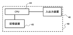
- FIG. 2 is a hardware configuration of the interference determination apparatus.
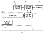
- a proton beam treatment system 100 for performing particle beam treatment includes an interference determination device 40, a treatment device operation unit 3f, a treatment device control unit 3A, and a treatment device 60.
- the interference determination device 40 includes a rotating gantry 20 and a treatment table 62 (see FIG. 3 respectively) and a patient 61 (see FIG. 3) or treatment devices 60 (the rotating gantry 20 and the treatment table 62). And the like, and includes an interference calculation unit 41, a 3D model storage unit 42, and a control signal input / output unit 43.
- the interference calculation unit 41 is a software function for analyzing interference determination, and is constructed on the CPU 44 mounted in the interference determination device 40 shown in FIG. Before the movement of the treatment device 60 starts, the interference calculation unit 41 performs a 3D model (rotary gantry model, irradiation nozzle model, treatment table model, X-ray imaging model installed in the treatment room, CBCT (Cone Beam CT). ) Model etc.) and the default patient 3D model are arranged in a virtual space imitating the treatment room in the same manner as the real space.
- a 3D model rotary gantry model, irradiation nozzle model, treatment table model, X-ray imaging model installed in the treatment room, CBCT (Cone Beam CT). ) Model etc.
- the 3D model of the treatment device 60 is moved to the target position in the virtual space, and the 3D model of the treatment device 60 and the 3D model of the patient 61 are moved.
- An interference determination simulation is performed to determine whether there is a collision with the 3D model of the treatment apparatus 60 or not.
- the shortest distance (distance to be determined) between each 3D model in the movement path of each 3D model is calculated, and this shortest distance is predetermined at the time of designing, manufacturing, or installing the apparatus. It is determined whether or not it is less than or equal to the operation permission interlock threshold. If it is determined that the shortest distance is less than or equal to the operation permission interlock threshold, an operation non-permission signal is output to the treatment device control unit 3A.
- the 3D model storage unit 42 stores 3D models of all the treatment apparatuses necessary for the interference calculation, a default 3D model as the model of the patient 61, and a 3D model of the treatment room, and FIG. As shown in FIG. 4, the storage device 45 is constructed.
- the control signal input / output unit 43 is an interface unit that exchanges control information with the treatment device control unit 3A, and corresponds to the input / output device 46 shown in FIG.
- the control signal input / output unit 43 inputs various control information regarding the operation of each device constituting the treatment device 60 from the treatment device control unit 3A into the interference determination device 40, and performs various controls such as an operation non-permission signal for the treatment device 60.
- the signal is output to the treatment device control unit 3A.
- the interference calculation unit 41 is connected to the 3D model storage unit 42 and the control signal input / output unit 43, and the treatment device control unit 3A is connected to the control signal input / output unit 43 and the treatment device 60.
- the treatment device operation unit 3 f is an input interface for an operator to perform various operations of the treatment device 60.
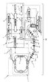
- FIG. 3 is a schematic configuration diagram of a proton beam treatment apparatus which is an example of the treatment apparatus 60 shown in FIG. 1.
- a proton beam treatment system 100 performs treatment by irradiating a diseased part (target) 61a of a patient 61 fixed to a treatment table 62 in a treatment room by irradiating the affected part 61a with a proton beam. It consists of a treatment device 60 for irradiation and a control system 3.
- the treatment device 60 includes a charged particle beam generation device 1, a high energy beam transport system 13, a rotary irradiation device 21, an irradiation device 20, and a treatment table 62 disposed in a treatment room.
- the charged particle beam generator 1 includes an ion source (not shown), a pre-accelerator 5 (for example, a linear charged particle beam generator such as a linear accelerator) and a synchrotron (accelerator) 2.
- the synchrotron has a high-frequency accelerator 14.
- the high energy beam transport system 13 is connected downstream of the charged particle beam generator 1 and transports the charged particle beam emitted from the charged particle beam generator 1 further downstream.
- the high energy beam transport system 13 includes a deflection electromagnet 11a that bends the charged particle beam emitted from the synchrotron 2, a quadrupole electromagnet 12a that adjusts the size of the charged particle beam, a beam position monitor 22a that measures the position of the charged particle beam, and It is comprised from the steering electromagnet 17a which correct
- the rotary irradiation device 21 connected downstream of the high energy beam transport system 13 and the irradiation device that irradiates the affected part of the patient with the charged particle beam connected to the rotary irradiation device 21, such as the rotary gantry 20, have a rotation mechanism. It is installed on a stand.
- the rotary irradiation device 21 includes a deflection electromagnet 11b for bending the charged particle beam transported by the high energy beam transport system 13, a quadrupole electromagnet 12b for adjusting the size of the charged particle beam, a beam position monitor 22b for measuring the position of the charged particle beam, A steering electromagnet 17b that corrects the beam position and a rotation irradiation device angle detection device 23 that measures the rotation angle of the rotation irradiation device 21 and transmits the rotation angle of the rotation irradiation device 21 to the control system 3 are configured.
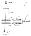
- FIG. 4 shows an outline of a scanning apparatus which is a typical example of an irradiation apparatus.
- the scanning device that is an example of the rotating gantry 20 includes a scanning electromagnet 20 a, a beam position monitor 20 c, a beam position measurement device 20 e, a beam dose monitor 20 d, a beam dose measurement device 20 f, and a signal processing device 30.
- a scanning electromagnet 20 a the scanning electromagnet 20 a
- a beam position monitor 20 c the scanning electromagnet 20 a
- a beam position measurement device 20 e the beam position measurement device 20 e
- a beam dose monitor 20 d the beam dose measurement device 20 f
- a signal processing device 30 a signal processing device
- the scanning electromagnet 20a scans the charged particle beam transported by the rotary irradiation device 21 according to the shape of the affected part.
- the beam position monitor 20c detects the position of the charged particle beam.
- the beam position measuring device 20e measures a signal from the beam position monitor 20c.
- the beam dose monitor 20d detects the dose of the charged particle beam.
- the beam dose measuring device 20f measures a signal from the beam dose monitor 20d.
- the signal processing device 30 processes signals from the beam position measuring device 20e and the beam dose measuring device 20f.
- the measurement data sent from the signal processing device 30 is sent to the control system 3 and recorded.
- the control system 3 includes the treatment device control unit 3A, the treatment device operation unit 3f, and the interference determination device 40 in FIG.
- the therapeutic device control unit 3A in FIG. 1 includes an overall control device 3a, an accelerator control device 3b, an irradiation control device 3c, a gantry control device 3d, a treatment table control device 3e, and an interlock device 4 shown in FIG. Consists of
- the overall control device 3a outputs various control signals to an accelerator control device 3b, an irradiation control device 3c, and an interlock device 4 to be described later, and controls the overall operation of the treatment device 60.
- the accelerator control device 3b controls the synchrotron 2, the high energy beam transport system 13, and the rotary irradiation device 21 based on a command from the overall control device 3a.
- the irradiation control device 3c controls the rotating gantry 20 based on a command from the overall control device 3a.
- the gantry control device 3d controls the rotary irradiation device 21 and the rotary gantry 20 based on a command from the irradiation control device 3c.
- the treatment table control device 3e controls the treatment table 62 based on a command from the irradiation control device 3c.
- the interlock device 4 monitors the safety of the overall control device 3a, the accelerator control device 3b, the irradiation control device 3c, and the gantry control device 3d, and sends a control signal for emergency stop to each control device in case of emergency. It is an apparatus for ensuring the safety of the patient 61 by outputting.
- proton ions generated by the ion source are accelerated by the pre-accelerator 5.
- the proton ions accelerated by the pre-stage accelerator 5 are further accelerated by the high-frequency accelerator 14 to a predetermined energy (for example, 50 MeV to 250 MeV) set in the synchrotron 2, and after reaching the predetermined energy, It is emitted to the energy beam transport system 13.
- a predetermined energy for example, 50 MeV to 250 MeV
- the charged particle beam emitted from the synchrotron 2 is transported further downstream by the high-energy beam transport system 13, and passes through the rotary irradiation device 21 and the rotary gantry 20 to the affected part 61 a in the patient 61 on the treatment table 62. Irradiated.
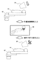
- FIG. 5 shows an outline of the interference determination.
- there are two treatment devices 60 to be subjected to interference determination that is, a rotating gantry 20 and a treatment table 62.
- the interference calculation unit 41 of the interference determination device 40 arranges the 3D model of the rotating gantry 20, the treatment table 62, and the patient 61 in the virtual space in the same arrangement as the treatment room when the system is activated.
- the control signal input / output unit 43 of the interference determination device 40 receives the current position information, target position information, and operation speed of the gantry from the gantry control device 3d in the treatment device control unit 3A of the control system 3, and the treatment table control device 3e.
- the current position information, target position information and operation speed of the treatment table 62 are received.
- the interference calculation unit 41 of the interference determination device 40 uses the movement request signal output from the overall control device 3a as a trigger to move each 3D model in the virtual space,
- the interference state with the treatment table 62 or the interference state between the rotating gantry 20 or the treatment table 62 and the patient 61 is analyzed.
- an operation non-permission signal is output for the treatment device 60, particularly the rotating gantry 20 and the treatment table 62.
- the operation non-permission signal is output to the overall control device 3a, and the overall control device 3a outputs an operation prohibition command to the gantry control device 3d and the treatment table control device 3e.
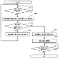
- FIG. 6 is a flowchart of the interference determination apparatus according to Embodiment 1 of the present invention.
- the process of the interference determination apparatus 40 is composed of the processes of S001 to S006 and S009, and is executed by the interference calculation unit 41.
- step S001 was the movement request signal output when the operator pressed the movement start button of the treatment apparatus 60 by the treatment apparatus operation section 3f input to the control signal input / output section 43? Determine whether or not. If it is determined that it has been input, the process proceeds to step S002. If it is determined that it has not been input, the determination in step S001 is executed again to wait for input of a movement request signal.
- the process proceeds to step S002, and before the treatment apparatus 60 is driven, from the various control information (current position, target position, set speed) of the treatment apparatus 60, from the current position of the treatment apparatus 60 to the target position. And the shortest distance between the treatment device 60 and the patient and the treatment device 60 is calculated.
- the current position acquires data of the treatment device 60 and is output from the treatment device control unit 3A to the control signal input / output unit 43.
- the control information of the target position and the set speed is input by the operator using the treatment device operation unit 3f, and is output from the treatment device control unit 3A to the control signal input / output unit 43.
- the shortest distance is calculated by placing a 3D model of the treatment device in the same manner as the actual trajectory and calculating the distance between the treatment devices 60 or between the treatment device 60 and the patient 61 at each point.
- step S003 the shortest distance calculated in step S002 is compared with the operation permission interlock threshold value, and it is determined whether or not the shortest distance is equal to or less than the operation permission interlock threshold value. If it is determined that the shortest distance is less than or equal to the operation permission interlock threshold, the process proceeds to step S004. If it is determined that the shortest distance is greater than the operation permission interlock threshold, the process proceeds to step S005.
- an operation permission signal is output to the overall control device 3a via the control signal input / output unit 43 in step S005.
- step S006 the overall control device 3a outputs a movement command for the treatment device 60 to the gantry control device 3d and the treatment table control device 3e based on the operation permission signal.
- step S009 it is determined in step S009 whether or not the moving treatment device 60 has reached the target position or the operation has been completed. If it is determined that the target position has been reached or the operation has been completed, the process is terminated. If it is determined that the target position has not been reached or the operation has not been completed, the determination in step S009 is performed again after a predetermined time has elapsed, and the target position is reached. Or continue the process until the end of the operation.
- the proton beam treatment system 100 that performs proton beam treatment according to the first embodiment of the present invention described above includes a treatment device 60 that irradiates the affected part 61a with a proton beam, and a treatment device control unit 3A that controls the operation of the treatment device 60.
- the interference determination apparatus 40 for preventing the collision between the treatment apparatus 60 and the patient 61 or the treatment apparatus 60 is provided. Among them, the interference determination device 40 receives control information of the treatment device 60 from the treatment device control unit 3A, and outputs a control signal to the treatment device 60, and a 3D of the treatment device 60.
- the 3D model storage unit 42 that stores each of the 3D model, the 3D model of the treatment room, and the 3D model of the patient 61, and the 3D model are arranged in the virtual space in the same manner as the real space before the treatment apparatus 60 starts moving.
- An interference calculation unit that performs an interference determination simulation for determining whether or not there is a collision between the treatment apparatus 60 and the patient 61 and a collision between the treatment apparatuses 60 by moving the 3D model to the target position in the virtual space based on the control signal 41.
- the weight is about 100 tons and it is not suitable for rapid deceleration, it is possible to avoid sudden deceleration of the beam irradiation gantry, so that it is possible to extend the life of the apparatus.
- the presence / absence of interference is determined using the 3D model of the treatment device 60, the 3D model of the treatment room, and the 3D model of the patient 61, the accuracy of interference determination can be improved.
- the interference calculation unit 41 determines whether the determination target distance is equal to or less than a predetermined operation permission interlock threshold with the shortest distance between the 3D model of the treatment device 60 and the other 3D model as the determination target distance. When it is determined that the determination target distance is equal to or less than the operation permission interlock threshold, an operation non-permission signal is output to the treatment device control unit 3A, so that treatment with higher throughput can be performed.
- the interference calculation unit 41 performs an interference determination simulation after receiving the movement request signal of the treatment apparatus 60 and before the movement of the treatment apparatus 60 starts.
- the interference calculation unit 41 of the interference determination apparatus 40 can minimize the waiting time by starting the analysis after the movement request is received. Furthermore, since the analysis process is performed only when necessary, an effect that the CPU load factor can be reduced is obtained.
- Embodiment 2 A proton beam therapy system and an interference determination apparatus according to Embodiment 2 of the present invention will be described with reference to FIG.
- the same components as those in the first embodiment are denoted by the same reference numerals, and description thereof is omitted. The same applies to the following embodiments.
- the presence or absence of interference on the trajectory from the current position of the treatment apparatus 60 to the target position is calculated before the treatment apparatus 60 moves. An aspect of prohibiting the operation of was described.
- a deceleration interlock threshold is separately provided in addition to the operation permission interlock threshold, and the deceleration start position is calculated before the treatment device 60 moves, Deceleration starts from that position.
- the configuration and operation of the proton beam treatment system and the interference determination device of the present embodiment are substantially the same as those of the proton beam treatment system and the interference determination device of Embodiment 1 described above, except for the configuration and operation of the interference calculation unit of the interference determination device. Operation is not described in detail.
- the interference calculation unit of the interference determination apparatus further analyzes a position where the distance between the 3D models is equal to or less than the deceleration interlock threshold greater than the predetermined operation permission interlock threshold, and the treatment apparatus is moving. When the position reaches the deceleration interlock threshold or less, a deceleration signal is output to the treatment device control unit 3A.
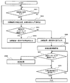
- FIG. 7 is a flowchart of the interference determination apparatus according to the second embodiment.
- step S002A the process proceeds to step S002A, and before driving the treatment device 60, whether or not there is interference in the trajectory from the current position of the treatment device 60 to the target position from various control information (current position, target position, set speed) of the treatment device 60
- the shortest distance between the treatment device 60 and the patient and the treatment device 60 is calculated, and the position where the shortest distance between the treatment device 60 and the patient 61 and the treatment device 60 matches the deceleration interlock threshold is calculated.
- step S003 the shortest distance calculated in step S002 is compared with the operation permission interlock threshold, and when the shortest distance between the treatment device 60, the patient 61, and the treatment device 60 is equal to or less than the operation permission interlock threshold.
- step S004 similar to that of the first embodiment is performed.
- step S003A the shortest distance between the treatment device 60, the patient 61, and the treatment device 60 is compared with the deceleration interlock threshold value, and it is determined whether or not the shortest distance is equal to or less than the deceleration interlock threshold value.
- step S003A If it is determined in step S003A that the shortest distance is larger than the deceleration interlock threshold, that is, if there is no position where the shortest distance between the treatment apparatus and the patient and the treatment apparatus matches the deceleration interlock threshold, the process proceeds to step S005.
- the process proceeds to steps S005, S006, and S009 to move and move the treatment device 60 normally as in the first embodiment.
- the process proceeds to step S005A.
- step S005A the position where the shortest distance matches the deceleration interlock threshold is recorded as the deceleration start position, and an operation permission signal is output to the treatment device 60.
- step S006A the overall control device 3a outputs a movement command for the treatment device 60 to the gantry control device 3d and the treatment table control device 3e based on the operation permission signal.
- step S007A it is determined whether or not the operation is completed. When it is determined that the operation is completed, the process is terminated. When it is determined that the operation is not completed, the process proceeds to step S007B.
- step S007B it is determined whether or not the moving treatment device 60 has reached the deceleration start position. If it is determined that the deceleration start position has been reached, the process proceeds to step S008. If it is determined that the deceleration start position has not been reached, the determination in step S007A is executed again to complete the operation or start deceleration. Wait to reach the position.
- step S008 a deceleration signal is output to the overall control device 3a.
- step S009 it is determined whether the moving treatment device 60 has reached the target position or the operation has ended, and the process reaches the target position or until the operation ends. Continue.
- the interference calculation unit 41 analyzes a position where the distance between the 3D models is equal to or less than a deceleration interlock threshold that is greater than a predetermined operation permission interlock threshold, and becomes less than the deceleration interlock threshold while the treatment apparatus is moving. When the position is reached, a deceleration signal is output to the treatment device control unit 3A.
- the margin threshold needs to be set larger, which is more than necessary. Deceleration occurs.
- the deceleration signal is output only when the shortest distance is equal to or less than the deceleration interlock threshold in the prior analysis, the treatment device 60 and the patient 61 or the treatment devices 60 approach each other. Only when the deceleration process can be performed. For this reason, the sudden stop of the treatment apparatus 60 can be prevented more reliably, and a safer movement of the treatment apparatus 60 can be realized.
- the deceleration start position the position where the deceleration interlock threshold and the shortest distance coincide with each other is described as the deceleration start position.
- the deceleration start position does not need to coincide with the deceleration interlock threshold, and the shortest distance is reduced.
- the position before the distance necessary for the therapeutic device 60 to decelerate from the position that coincides with the interlock threshold value can be recorded as the deceleration start position.
- the presence or absence of interference on the trajectory from the current position of the treatment apparatus 60 to the target position is calculated before the treatment apparatus 60 moves. An aspect of prohibiting the operation of was described.
- a deceleration interlock threshold is provided in the same manner as in the second embodiment in addition to the operation permission interlock threshold. Processing related to the lock threshold is performed in real time while the treatment device 60 is moving.
- the configuration and operation of the proton beam treatment system and the interference determination device of the present embodiment are substantially the same as those of the proton beam treatment system and the interference determination device of Embodiment 1 described above, except for the configuration and operation of the interference calculation unit of the interference determination device. Operation is not described in detail.
- the interference calculation unit of the interference determination apparatus further determines whether the distance between the 3D models is less than or equal to a predetermined deceleration permission threshold greater than a predetermined operation permission interlock threshold in real time during the movement of the treatment apparatus. When it is determined that the value is equal to or less than the deceleration interlock threshold, a deceleration signal is output to the treatment device control unit 3A.
- FIG. 8 is a flowchart of the interference determination apparatus according to the third embodiment.
- step S002A is in step S002 shown in FIG. 6
- step S005A is in step S005 shown in FIG.
- step S007B is replaced with step S007.
- step S006A the overall control device 3a outputs a movement command for the treatment device 60 to the gantry control device 3d and the treatment table control device 3e based on the operation permission signal, and then the process moves to step S007.
- step S007 it is determined whether or not the calculated distance is equal to or less than the deceleration interlock threshold. judge. When it is determined that the distance is equal to or smaller than the deceleration interlock threshold, the process proceeds to step S008. When it is determined that the distance is greater than the deceleration interlock threshold, the process proceeds to step S009.
- step S008 the control signal input / output unit 43 outputs a deceleration signal to the overall control device 3a, and the overall control device 3a outputs a deceleration command to the gantry control device 3d and the treatment table control device 3e based on the input deceleration signal.
- step S008 When it is determined that the distance is greater than the deceleration interlock threshold and after the deceleration signal is output in step S008, the process moves to step S009.
- step S009 it is determined whether or not the moving treatment device 60 has reached the target position, or the operation has been completed, and if the treatment device has reached the target position or the user has finished operating the treatment device Then, the interference determination process ends. If the therapeutic device has not reached the target position and the user has not finished operating the therapeutic device, the process returns to step S007, and the processes of steps S007 to S009 are repeated.
- the interference calculation unit 41 determines whether the distance between the 3D models is equal to or less than a predetermined deceleration permission threshold greater than a predetermined operation permission interlock threshold in real time during the movement of the treatment apparatus.
- a deceleration signal can be output to the treatment device control unit 3A, so that a deceleration process can be provided, and a sudden stop of the treatment device 60 can be prevented when there is a risk of a collision. it can.
- the treatment of the present embodiment is more effective than the treatment shown in the second embodiment. Since the calculation load before the operation of the apparatus is reduced, the waiting time for the analysis result can be reduced and the treatment can be performed smoothly.
- the treatment device 60 that can calculate the trajectory to the target position is analyzed by the processing method of the second embodiment, and the treatment device 60 that cannot calculate the trajectory to the target position is analyzed by the processing method of the third embodiment.
- the CPU load factor can be reduced by appropriately combining the processes.
- FIG. 9 is a block diagram of the radiation therapy system according to the fourth embodiment.
- the interference determination device 40A of the proton beam treatment system 100A includes a patient volume measurement device 47 that images a patient 61 and a patient that creates a patient 3D model from patient volume data acquired by the patient volume measurement device 47.
- a model creation unit 49 is further provided.
- the interference calculation unit 41A executes an interference determination simulation using the patient 3D model created by the patient model creation unit 49.
- a TOF (Time of Flight) camera As the patient volume measuring device 47, a TOF (Time of Flight) camera, a stereo camera, or a light cutting type camera is assumed, but other devices are also possible.
- a patient volume measuring device 47 that images the patient 61 and a patient model creating unit 49 that creates a patient 3D model based on the result captured by the patient volume measuring device 47
- a default patient Interference determination using the patient 3D model closer to the actual patient than the 3D model is possible, the operation permission interlock threshold can be reduced, and treatment with higher throughput is possible.
- Embodiment 5 A proton beam therapy system and an interference determination apparatus according to Embodiment 5 of the present invention will be described with reference to FIG.
- FIG. 10 is a block diagram of a radiation therapy system according to the fifth embodiment.
- the interference determination device 40B of the proton beam treatment system 100B includes a TOF camera 47A as a patient volume measuring device.
- the patient model creation unit 49A creates a patient 3D model using the depth data acquired by the TOF camera 47A.
- the interference calculation unit 41B executes an interference determination simulation using the patient 3D model created by the patient model creation unit 49A.
- the patient volume measuring device is a TOF camera 47A.
- photographing devices such as cameras are likely to break down due to the influence of neutrons.
- the TOF camera has a feature that it is inexpensive and does not require positioning, calibration, or the like as compared with other three-dimensional measuring units such as a stereo camera and a light cutting type camera. For this reason, the TOF camera 47A is suitable for use in a particle beam therapy room. Furthermore, since the TOF camera has a short measurement time, the burden on the patient is small and the throughput can be further improved.
- the proton beam treatment system and the interference determination apparatus according to the sixth embodiment are the same as those in the interference determination apparatus described in the fourth embodiment.
- the patient model creation unit 49B includes measurement data when the patient 61 is not placed on the treatment table 62, and the patient A model is created from the difference of measurement data when 61 is placed.
- FIG. 11 is a block diagram of a radiation therapy system according to the sixth embodiment.
- the patient model creation unit 49B in the interference determination apparatus 40C of the proton beam treatment system 100C has measurement data when the patient 61 is not placed on the treatment table, and when the patient 61 is placed on the treatment table.
- the patient 3D data is created from the difference from the measurement data.
- the interference calculation unit 41C executes an interference determination simulation using the patient 3D model created by the patient model creation unit 49B.
- the depth data of only the treatment table 62 is acquired by the patient volume measurement device 47 in advance at the position where the patient 61 is placed on the treatment table 62. Thereafter, the patient 61 is placed on the treatment table 62 at the time of treatment, and depth data when the patient 61 is mounted is separately acquired by the patient volume measuring device 47.
- the patient model creation unit 49B calculates a difference between these data and creates a patient 3D model.
- the display device for example, an interference calculation model display unit 48 of FIG. 12 described later, etc.
- the display device can be suitably used for the calculated difference data and the created patient model.
- the patient model creation unit 49B creates patient 3D data from the difference between the measurement data when the patient 61 is not placed on the treatment table 62 and the measurement data when the patient 61 is placed on the treatment table 62.
- the model is created from the difference from the data of the treatment table 62 acquired in advance, the patient region can be specified more accurately, and noise removal becomes easy. Further, by performing the difference processing, it becomes possible to cancel the systematic error, and it is possible to create a more accurate patient 3D model.
- Embodiment 7 A proton beam therapy system and an interference determination apparatus according to Embodiment 7 of the present invention will be described with reference to FIG.
- the proton beam treatment system and the interference determination apparatus according to the seventh embodiment display a model used for interference determination and the result of interference determination.
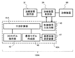
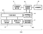
- FIG. 12 is a block diagram of the radiation therapy system according to the seventh embodiment.
- the interference determination device 40D of the proton beam treatment system 100D of the present embodiment includes a 3D model in the virtual space and an interference calculation model display unit (interference determination result display device) 48 that displays the interference determination result.
- the interference calculation unit 41D outputs a display signal to the interference calculation model display unit 48 so as to display the interference occurrence position as an interference calculation result.
- a display signal is output so that the model of the interference position is displayed on the model of the current position being displayed. It is desirable that the displayed model highlights and highlights the collision location so that the position where the collision occurs before the treatment apparatus 60 moves can be grasped.
- the model to be displayed enables operations such as enlargement / reduction and rotation.
- the surveillance camera can also confirm interference at a position that is a blind spot.
- an interference calculation model display unit 48 that displays the 3D model in the virtual space and the interference determination result, it is possible to easily grasp whether or not interference occurs and the state of interference when it occurs. it can. For this reason, the target position and setting speed of the treatment device 60 can be corrected more easily, recovery can be performed more quickly when interference occurs, and treatment with higher throughput is possible.
- Embodiment 8 A proton beam therapy system and an interference determination apparatus according to Embodiment 8 of the present invention will be described with reference to FIG.
- the proton beam treatment system and the interference determination apparatus always monitor the state of the treatment apparatus 60 using the three-dimensional measurement unit 50, and reflect the deformation generated in the treatment apparatus 60 in the 3D model. Perform proper interference determination.
- FIG. 13 is a block diagram of a radiation therapy system according to the eighth embodiment.
- the interference determination device 40E of the proton beam treatment system 100E of this embodiment further includes a three-dimensional measurement unit 50 that constantly measures the shape of the treatment device 60 and constantly monitors the deformation.
- the calculation unit 41E corrects the 3D model of the treatment device 60 using the deformation amount data of the treatment device 60 measured by the three-dimensional measurement unit 50, and performs an interference determination simulation.
- the apparatus further includes a three-dimensional measurement unit 50 that constantly monitors the deformation of the treatment apparatus, and the interference calculation unit 41E corrects the 3D model using the deformation amount data measured by the three-dimensional measurement unit 50 to determine interference. Perform a simulation. Since the treatment apparatus 60 used for particle beam therapy, particularly the treatment table 62, requires a highly flexible operation and a wide operation range in order to perform beam irradiation from various angles, bending is likely to occur. On the other hand, more accurate interference determination can be performed by monitoring such deflection by the three-dimensional measurement unit 50 and reflecting it on the 3D model. As a result, the operation permission interlock threshold can be set smaller and more accurately, and safer treatment can be performed with high throughput.
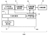
- the proton beam treatment system and the interference determination apparatus acquire device deflection information from the treatment apparatus 60 and perform accurate interference determination.
- FIG. 14 is a block diagram of the radiation therapy system according to the ninth embodiment.
- the interference determination device 40F of the proton beam treatment system 100F detects distortion such as a force sensor installed in the treatment device 60 instead of the three-dimensional measurement unit 50 described in the eighth embodiment. Based on the device information, the 3D model of the treatment device 60 is corrected.
- a force sensor 51 is employed as a strain detection device. The force sensor 51 constantly monitors the deformation of the treatment device 60. Further, the interference calculation unit 41F corrects the 3D model of the treatment apparatus 60 using the deformation amount data measured by the force sensor 51 and performs an interference determination simulation.
- a force sensor 51 that constantly monitors the deformation of the treatment device 60 is further provided, and the interference calculation unit 41F corrects the 3D model using the deformation amount data measured by the force sensor 51 and performs an interference determination simulation. As a result, more accurate interference determination can be performed, and the operation permission interlock threshold can be reduced.
- the rotary gantry 20 and the treatment table 62 are exemplified as the movable treatment device 60 that performs interference determination by the interference determination device 40 in the above-described embodiments
- the treatment device 60 configured to be movable is limited to these.
- in-room CT for imaging the patient 61 with the treatment table 62 during irradiation in which the charged particle beam transported by the high energy beam transport system 13 is irradiated onto the affected part 61a, and the patient 61 on the treatment table 62 as a center.
- examples include a C-arm that rotates the X-ray tube and the X-ray detector, and a snout that holds a collimator and a bolus.
- a treatment device that can calculate a trajectory up to a position and a device having two or more movable axes, for example, a treatment table, can be a treatment device that cannot calculate a trajectory up to a target position.
- the timing for performing the interference determination simulation is set to be immediately before the start of movement of the treatment apparatus after receiving the movement request signal of the treatment apparatus 60
- the timing may be before the start of movement of the treatment apparatus.
- it may be after creation of a treatment plan in which various operations of the treatment device 60 are determined to some extent.
- various control information on the operation of the treatment apparatus 60 is abundant and the accuracy is in line with the actual movement. It is desirable that it be received and immediately before the start of movement of the treatment device.
- the shortest distance between the 3D model of the treatment device 60 and another 3D model is set as the determination target distance
- the case where it is determined whether the determination target distance is equal to or less than a predetermined operation permission interlock threshold has been described.
- the method for determining the interference between the 3D model of the treatment device 60 and the other 3D model is not limited to this. For example, it is also possible to determine whether there is an overlapping portion in the coordinate space of the 3D model. is there.
- Control system 3A Treatment device controller (control device) 20 ... Rotating gantry (irradiation device) 40, 40A, 40B, 40C, 40D, 40E, 40F ... interference determination devices 41, 41A, 41B, 41C, 41D, 41E, 41F ... interference calculation unit 42 ... 3D model storage unit (3D database) 43 ... Control signal input / output unit 44 ... CPU 45 ... Storage device 46 ... Input / output devices 47, 47A ... Patient volume measuring device 48 ... Interference calculation model display unit (interference determination result display device) 49, 49A, 49B ... patient model creation unit 50 ... three-dimensional measurement unit 51 ... force sensor 60 ... treatment device 61 ... patient 61a ... affected part (target) 62 ... treatment table 100, 100A, 100B, 100C, 100D, 100E, 100F ... proton beam treatment system (radiotherapy system)
Landscapes
- Radiation-Therapy Devices (AREA)
Applications Claiming Priority (2)
| Application Number | Priority Date | Filing Date | Title |
|---|---|---|---|
| JP2017-060056 | 2017-03-24 | ||
| JP2017060056A JP6910823B2 (ja) | 2017-03-24 | 2017-03-24 | 放射線治療システムおよび干渉判定装置 |
Publications (1)
| Publication Number | Publication Date |
|---|---|
| WO2018173468A1 true WO2018173468A1 (ja) | 2018-09-27 |
Family
ID=63586015
Family Applications (1)
| Application Number | Title | Priority Date | Filing Date |
|---|---|---|---|
| PCT/JP2018/002164 Ceased WO2018173468A1 (ja) | 2017-03-24 | 2018-01-24 | 放射線治療システムおよび干渉判定装置 |
Country Status (2)
| Country | Link |
|---|---|
| JP (1) | JP6910823B2 (enExample) |
| WO (1) | WO2018173468A1 (enExample) |
Families Citing this family (2)
| Publication number | Priority date | Publication date | Assignee | Title |
|---|---|---|---|---|
| JP2020099438A (ja) * | 2018-12-20 | 2020-07-02 | キヤノンメディカルシステムズ株式会社 | 干渉判定装置及びモデル生成装置 |
| JP7570866B2 (ja) * | 2020-09-25 | 2024-10-22 | キヤノンメディカルシステムズ株式会社 | 医療用監視装置、及び医療用監視システム |
Citations (3)
| Publication number | Priority date | Publication date | Assignee | Title |
|---|---|---|---|---|
| JP2010131270A (ja) * | 2008-12-05 | 2010-06-17 | Mitsubishi Heavy Ind Ltd | 治療用放射線照射装置動作制御装置および治療用放射線照射装置動作制御方法 |
| JP2014090896A (ja) * | 2012-11-05 | 2014-05-19 | Mitsubishi Electric Corp | 粒子線治療用干渉チェック装置 |
| JP2014128352A (ja) * | 2012-12-28 | 2014-07-10 | Mitsubishi Electric Corp | 放射線治療装置の衝突防止インターロック装置及び放射線治療システム |
Family Cites Families (3)
| Publication number | Priority date | Publication date | Assignee | Title |
|---|---|---|---|---|
| JP5276575B2 (ja) * | 2009-11-30 | 2013-08-28 | 三菱電機株式会社 | 放射線治療干渉チェック装置及び放射線治療干渉チェック方法 |
| US10493298B2 (en) * | 2013-08-02 | 2019-12-03 | Varian Medical Systems, Inc. | Camera systems and methods for use in one or more areas in a medical facility |
| WO2016008052A1 (en) * | 2014-07-16 | 2016-01-21 | Dalhousie University | Method and system for cancer treatment with radiation |
-
2017
- 2017-03-24 JP JP2017060056A patent/JP6910823B2/ja active Active
-
2018
- 2018-01-24 WO PCT/JP2018/002164 patent/WO2018173468A1/ja not_active Ceased
Patent Citations (3)
| Publication number | Priority date | Publication date | Assignee | Title |
|---|---|---|---|---|
| JP2010131270A (ja) * | 2008-12-05 | 2010-06-17 | Mitsubishi Heavy Ind Ltd | 治療用放射線照射装置動作制御装置および治療用放射線照射装置動作制御方法 |
| JP2014090896A (ja) * | 2012-11-05 | 2014-05-19 | Mitsubishi Electric Corp | 粒子線治療用干渉チェック装置 |
| JP2014128352A (ja) * | 2012-12-28 | 2014-07-10 | Mitsubishi Electric Corp | 放射線治療装置の衝突防止インターロック装置及び放射線治療システム |
Also Published As
| Publication number | Publication date |
|---|---|
| JP2018161264A (ja) | 2018-10-18 |
| JP6910823B2 (ja) | 2021-07-28 |
Similar Documents
| Publication | Publication Date | Title |
|---|---|---|
| JP7416742B2 (ja) | 粒子線治療における自動処置 | |
| EP3375486B1 (en) | Particle therapy system | |
| JP5496414B2 (ja) | 粒子線治療装置 | |
| US7834334B2 (en) | Particle therapy system | |
| JP5896211B2 (ja) | 荷電粒子照射システムおよび荷電粒子照射システムの作動方法 | |
| WO2017073683A1 (ja) | 中性子捕捉療法システム | |
| JP2014128352A (ja) | 放射線治療装置の衝突防止インターロック装置及び放射線治療システム | |
| TWI766762B (zh) | 放射治療系統及其安全聯鎖控制方法 | |
| CN113952636B (zh) | 放射治疗系统及其安全联锁控制方法 | |
| WO2018116354A1 (ja) | 放射線照射計画装置、臨床判断支援装置およびプログラム | |
| CN108348767A (zh) | 粒子束治疗系统 | |
| WO2020137234A1 (ja) | 粒子線治療システムおよび線量分布評価システム、ならびに粒子線治療システムの作動方法 | |
| JP2016144573A (ja) | 画像処理装置および粒子線治療装置 | |
| JP6910823B2 (ja) | 放射線治療システムおよび干渉判定装置 | |
| JP6465283B2 (ja) | 放射線治療システム | |
| WO2022194890A1 (en) | System and method for assessing the performance of a radiotherapy apparatus | |
| JP7220403B2 (ja) | 粒子線治療システム、計測粒子線ct画像生成方法、およびct画像生成プログラム | |
| WO2022017193A1 (zh) | 放射治疗系统及其安全联锁控制方法 | |
| US20110057124A1 (en) | Radiation therapy apparatus and method for monitoring an irradiation | |
| JP6968761B2 (ja) | 放射線治療システムおよび治療計画データの検証方法 | |
| JP2019122555A (ja) | 治療計画システム | |
| CN118369139A (zh) | 使用非正交机载成像进行放射治疗的位置验证和校正 |
Legal Events
| Date | Code | Title | Description |
|---|---|---|---|
| 121 | Ep: the epo has been informed by wipo that ep was designated in this application |
Ref document number: 18770681 Country of ref document: EP Kind code of ref document: A1 |
|
| NENP | Non-entry into the national phase |
Ref country code: DE |
|
| 122 | Ep: pct application non-entry in european phase |
Ref document number: 18770681 Country of ref document: EP Kind code of ref document: A1 |