WO2018168910A1 - 照明装置および光束制御部材 - Google Patents
照明装置および光束制御部材 Download PDFInfo
- Publication number
- WO2018168910A1 WO2018168910A1 PCT/JP2018/009910 JP2018009910W WO2018168910A1 WO 2018168910 A1 WO2018168910 A1 WO 2018168910A1 JP 2018009910 W JP2018009910 W JP 2018009910W WO 2018168910 A1 WO2018168910 A1 WO 2018168910A1
- Authority
- WO
- WIPO (PCT)
- Prior art keywords
- light
- emitting element
- light emitting
- axis
- incident
- Prior art date
- Legal status (The legal status is an assumption and is not a legal conclusion. Google has not performed a legal analysis and makes no representation as to the accuracy of the status listed.)
- Ceased
Links
Images






Classifications
-
- F—MECHANICAL ENGINEERING; LIGHTING; HEATING; WEAPONS; BLASTING
- F21—LIGHTING
- F21S—NON-PORTABLE LIGHTING DEVICES; SYSTEMS THEREOF; VEHICLE LIGHTING DEVICES SPECIALLY ADAPTED FOR VEHICLE EXTERIORS
- F21S2/00—Systems of lighting devices, not provided for in main groups F21S4/00 - F21S10/00 or F21S19/00, e.g. of modular construction
Definitions
- the present invention relates to a lighting device and a light flux controlling member.
- LEDs light-emitting diodes
- Examples of such an illuminating device include a bulb-type illuminating device having an LED as a light source, a fluorescent tube-type illuminating device, and a surface light source device having a plurality of LEDs arranged on a plane as a light source.
- the said surface light source device is useful as a backlight of a liquid crystal besides the use which illuminates the room.
- a surface light source device for the backlight a surface light source device in which LEDs of a plurality of colors are regularly arranged in a plane direction is known. This surface light source device suppresses the occurrence of local color unevenness by a specific regular arrangement of LEDs (see, for example, Patent Document 1).
- the pitch between LEDs, the LED arrangement, the light emission intensity of each LED, etc. may be required. For this reason, a surface light source device is required to achieve uniform surface light emission without requiring individual adjustment of LEDs.
- the illuminating device is arranged side by side in a direction along the first axis, the light emission colors thereof are different from each other, and the optical axes along the second axis perpendicular to the first axis are respectively set.
- a diffusing member disposed at a position away from the light source, wherein the light flux controlling member separates the first light emitting element and the second light emitting element from each other along the second axis.
- an incident part for allowing the emitted light of the first light emitting element and the second light emitting element to enter, and a part of the light incident at the incident part orthogonal to the first axis and the second axis Total reflection in the direction along the third axis And the total reflection portion in the direction along the third axis, the first light emitting element and the second light emitting element adjacent to the optical axis end of the first light emitting element and the incident position.
- An exit part for emitting another part of the light incident from the part to the outside, and the third reflection part from the end opposite to the optical axis in the direction along the third axis of the total reflection part.
- a light guide portion that extends in a direction along the axis and guides incident light in a direction along the third axis and emits the light outward, and the illumination device includes the first light emitting element.
- A1 In a cross section including the optical axis and the optical axis of the second light emitting element, an intersection of one of the first light emitting element and the second light emitting element and the optical axis is denoted by A1, the first light emitting element and The other light emitting element of the second light emitting elements in the direction along the first axis.
- An end on one light emitting element side is A2, and an end on the other light emitting element side in the direction along the first axis of a part through which the emitted light of the one light emitting element passes in the emitting portion is B1, Of the portion through which the emitted light of the other light emitting element passes in the emitting portion, the end opposite to the one light emitting element in the direction along the first axis passes through B2, and passes through A1 and B1.
- the intersection of the straight line with the diffusion member is C1
- the intersection of the straight line with the diffusion member passing through A2 and B2 is C2
- the C1 is more than the first axis than the C2. It is located outside in the direction along.
- the light flux controlling member according to the present invention is the light flux controlling member used in the illuminating device, wherein the light emitting part and the light incident part are both in a direction along the first axis.
- the positions of both ends of the emitting part are positions that are further away from the positions of the optical axes of the first light emitting element and the second light emitting element.
- the present invention it is possible to realize uniform surface light emission without the need for individual adjustment of the light emitting elements in the light emission by mixing the light emitting elements of a plurality of colors.
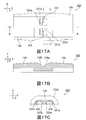
- FIG. 1A is a plan view schematically showing the illumination device (surface light source device) according to the first embodiment of the present invention
- FIG. 1B is an enlarged view of a portion B in FIG. 1A
- FIG. 1C is an enlarged view showing a main part of a cross section of the illumination device taken along line CC in FIG. 1A
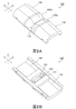
- 2A is a perspective view from the front side of the light flux controlling member in the first embodiment
- FIG. 2B is a perspective view from the back side of the light flux controlling member.
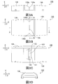
- 3A is a front view of the light flux controlling member in the first embodiment
- FIG. 3B is a plan view of the light flux controlling member
- FIG. 3C is a bottom view of the light flux controlling member.
- 3D is a side view of the light flux controlling member.
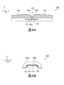
- 4A is a view showing a cross section taken along line AA in FIG. 3B of the light flux controlling member in the first embodiment, and FIG. 4B is taken along line BB in FIG. 3B of the light flux controlling member. It is a figure which shows a cross section.
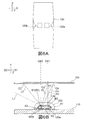
- 5A is a front view of the light scattering member in the first embodiment
- FIG. 5B is a bottom view of the light scattering member
- FIG. 5C is a side view of the light scattering member.
- 5D is a cross-sectional view of the light scattering member taken along line DD in FIG. 5B.
- FIG. 6A is a diagram schematically showing a positional relationship between the light flux controlling member and the light emitting element in the first embodiment
- FIG. 6B is a diagram of the emitted light on the XY plane from the light emitting element. It is a figure for demonstrating an output angle.
- FIG. 7A is a diagram schematically showing a light emitting element and a light flux controlling member in the surface light source device E1 according to the first example of the first embodiment.
- FIG. 7B is a graph showing the relationship between the position in the X direction of the central portion of the surface light source device E1 in the Z direction and the chromaticity of light that illuminates the cover.
- FIG. 7C shows the position in the X direction of the central portion in the Z direction of the light flux controlling member of the surface light source device E1 and the illuminance at the cover of the emitted light derived from each of the first and second light emitting elements from the emitting portion. It is a graph which shows the relationship.
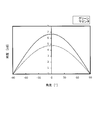
- FIG. 8 is a graph showing the relationship between the emission angle of emitted light and the luminous intensity of an example of the first light emitting element and the second light emitting element in the embodiment of the present invention.
- FIG. 9A is a diagram schematically illustrating an emission angle of emitted light of the light emitting element in the light flux controlling member of the surface light source device E2 according to the second example of the first embodiment.
- FIG. 9B is a graph showing the relationship between the position in the X direction of the central portion of the light flux controlling member in the Y direction of the surface light source device E2 and the chromaticity of light that illuminates the cover.
- FIG. 9C shows the position in the X direction of the central portion of the surface light source device E2 in the Y direction of the light flux controlling member, and the illuminance at the cover of the emitted light derived from each of the first and second light emitting elements from the emitting portion. It is a graph which shows the relationship.
- FIG. 10A is a diagram schematically showing an emission angle of emitted light of the light emitting element in the light flux controlling member of the surface light source device C1 according to the first example in the comparative example of the present invention.
- FIG. 10A is a diagram schematically showing an emission angle of emitted light of the light emitting element in the light flux controlling member of the surface light source device C1 according to the first example in the comparative example of the present invention.
- FIG. 11A is a diagram schematically illustrating an emission angle of emitted light of the light emitting element and the light flux controlling member in the surface light source device E3 according to the third example of the first embodiment.
- FIG. 11A is a diagram schematically illustrating an emission angle of emitted light of the light emitting element and the light flux controlling member in the surface light source device E3 according to the third example of the first embodiment.
- FIG. 11B is a graph showing the relationship between the position in the X direction of the central portion in the Z direction of the light flux controlling member in the surface light source device E3 and the chromaticity of light that illuminates the cover.
- FIG. 11C shows the position in the X direction of the central portion in the Z direction of the light flux controlling member in the surface light source device E3, and the illuminance on the cover of the emitted light derived from each of the first and second light emitting elements from the emitting portion. It is a graph which shows the relationship.
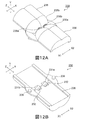
- FIG. 12A is a perspective view from the front side of the light flux controlling member in the second embodiment of the present invention
- FIG. 12B is a perspective view from the back side of the light flux controlling member.
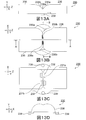
- FIG. 13A is a front view of the light flux controlling member in the second embodiment
- FIG. 13B is a plan view of the light flux controlling member
- FIG. 13C is a bottom view of the light flux controlling member
- 13D is a side view of the light flux controlling member.
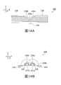
- 14A is a view showing a cross section taken along line AA in FIG. 13B of the light flux controlling member in the second embodiment
- FIG. 14B is taken along line BB in FIG. 13B of the light flux controlling member. It is a figure which shows a cross section.
- FIG. 15A is a diagram schematically illustrating an emission angle of emitted light from the light emitting element and the light flux controlling member in the surface light source device according to the second embodiment.
- FIG. 15A is a diagram schematically illustrating an emission angle of emitted light from the light emitting element and the light flux controlling member in the surface light source device according to the second embodiment.
- FIG. 15A is a diagram schematically illustrating an emission angle of emitted light from the
- FIG. 15B shows the position in the X direction of the central portion in the Z direction of the light flux controlling member in the surface light source device E4 of the example of the second embodiment, and the first and second light emitting elements from the emitting portion, respectively. It is a graph which shows the relationship with the illumination intensity in the cover of the emitted light derived from.
- FIG. 15C shows the position in the X direction of the central portion in the Z direction of the light flux controlling member in the surface light source device E5 of another example of the second embodiment, and the first and second light emitting elements from the emitting portion. It is a graph which shows the relationship with the illumination intensity in the cover of the emitted light originating in each of these.
- FIG. 15C shows the position in the X direction of the central portion in the Z direction of the light flux controlling member in the surface light source device E5 of another example of the second embodiment, and the first and second light emitting elements from the emitting portion. It is a graph which shows the relationship with the illumination intensity in the cover of the emitted light
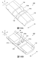
- FIG. 16A is a perspective view from the front side of the light flux controlling member in the third embodiment of the present invention
- FIG. 16B is a perspective view from the back side of the light flux controlling member.
- FIG. 17A is a bottom view of the light flux controlling member in the third embodiment
- FIG. 17B is a view showing a cross section of the light flux controlling member taken along line BB in FIG. 17A
- FIG. It is a figure which shows the cross section which follows the CC line
- FIG. 17A is a bottom view of the light flux controlling member in the third embodiment
- FIG. 17B is a view showing a cross section of the light flux controlling member taken along line BB in FIG. 17A
- FIG. It is a figure which shows the cross section which follows the CC line
- FIG. 19A is a diagram schematically illustrating an emission angle of emitted light of the light emitting element and the light flux controlling member in the surface light source device E6 as an example in the fourth embodiment of the present invention.
- FIG. 19B is a graph showing the relationship between the position in the X direction of the central portion in the Z direction of the light flux controlling member in the surface light source device E6 and the chromaticity of light that illuminates the cover.
- FIG. 19C is a graph showing the relationship between the position in the X direction of the central portion in the Z direction in the surface light source device E6 and the illuminance at the cover of the emitted light derived from each of the first and second light emitting elements from the emitting portion. It is.
- FIG. 19B is a graph showing the relationship between the position in the X direction of the central portion in the Z direction of the light flux controlling member in the surface light source device E6 and the chromaticity of light that illuminates the cover.
- FIG. 19C is a graph showing the relationship between
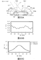
- FIG. 20A is a diagram schematically showing an emission angle of emitted light of the light emitting element and the light flux controlling member in another example of the surface light source device E7 in the fourth embodiment.
- FIG. 20B is a graph showing the relationship between the position in the X direction of the central portion in the Z direction of the surface light source device E7 and the chromaticity of light that illuminates the cover.
- FIG. 20C is a graph showing the relationship between the position in the X direction of the central portion in the Z direction in the surface light source device E7 and the illuminance on the cover of the emitted light derived from each of the first and second light emitting elements from the emitting portion. It is.
- FIG. 1A is a plan view schematically showing the illumination device (surface light source device) according to the first embodiment of the present invention
- FIG. 1B is an enlarged view of a portion B in FIG. 1A
- FIG. 1C is an enlarged view showing a main part of a cross section of the illumination device taken along line CC in FIG. 1A.
- the surface light source device 100 includes a substrate 110, a plurality of light emitting elements disposed on the substrate 110, a plurality of light flux control members 130 disposed at positions covering the light emitting elements on the substrate 110, and individual light flux control members.
- the substrate 110 is a member for supporting the light emitting element and the light flux controlling member 130.
- the substrate 110 may be a substrate normally used in a surface light source device, and includes a wiring for the light emitting element, a light diffusion layer for reflecting and diffusing incident light toward the cover 150, and the like.
- the substrate 110 supports the light emitting element and the light flux controlling member 130 disposed at predetermined intervals in the direction along the X axis (X direction) and the direction along the Z axis (Z direction).
- the substrate 110 is made of a metal having high thermal conductivity such as aluminum or copper. In the case where the substrate 110 does not require high thermal conductivity, the substrate 110 can be made of a material having relatively low thermal conductivity such as a resin substrate obtained by impregnating a glass nonwoven fabric with an epoxy resin.
- the X axis (“first axis” in the claims) and the Z axis (“third axis” in the claims) are parallel to the substrate 110 and orthogonal to each other. It is a virtual axis set to do.
- the pair of light emitting elements (the first light emitting element 120a and the second light emitting element 120b) are arranged in a direction along the X axis.
- the Y axis (the “second axis” in the claims) is a virtual axis set to be orthogonal to the X axis (first axis) and the Z axis (second axis).
- the direction along the X axis may be simply referred to as “X direction”
- the direction along the Y axis may be simply referred to as “Y direction”
- the direction along the Z axis may be simply referred to as “Z direction”.
- the X direction may mean only one direction along the X axis, or may mean two opposite directions along the X axis. The same applies to the Y direction and the Z direction.
- each of the first light emitting element 120a and the second light emitting element 120b is a light emitting diode (LED).
- the first light emitting element 120a and the second light emitting element 120b are arranged side by side in the X direction.
- Each of the first light emitting element 120a and the second light emitting element 120b has an optical axis along the Y direction.
- the first light emitting element 120a and the second light emitting element 120b emit light of different colors.
- that the color of the emitted light is different means that the spectral distribution of the emitted light is different. Therefore, even if the emitted light has the same color, the color of the emitted light may be different.
- the emission color of the first light emitting element 120a is magenta
- the emission color of the second light emitting element 120b is green.
- the light flux controlling member 130 and the light scattering member 140 will be described later.
- the cover 150 is a member that emits light emitted from the light flux controlling member 130, and usually has translucency and light diffusibility, and is also referred to as a diffusion member.
- the cover 150 is, for example, a resin flat plate, is opposed to the substrate 110, and is disposed away from any light flux controlling member 130 in the Y direction.
- Examples of the material of the cover 150 include a light transmissive resin such as polymethyl methacrylate (PMMA), polycarbonate (PC), polystyrene (PS), styrene / methyl methacrylate copolymer resin (MS), and a light transmissive resin. Glass.
- the light diffusibility of the cover 150 can be imparted to the cover 150 by a conventional method.
- the cover 150 can be imparted by roughening the surface of the cover 150, or a scatterer such as a bead can be provided in the cover 150. It can be applied by dispersing.
- FIG. 2A is a perspective view from the front side of the light flux controlling member in the first embodiment
- FIG. 2B is a perspective view from the back side of the light flux controlling member
- 3A is a front view of the light flux controlling member
- FIG. 3B is a plan view of the light flux controlling member
- FIG. 3C is a bottom view of the light flux controlling member
- FIG. 3D is the light flux controlling member. It is a side view of a control member.
- 4A is a diagram showing a cross section of the light flux controlling member taken along line AA in FIG. 3B
- FIG. 4B is a diagram showing a cross section of the light flux controlling member taken along line BB in FIG. 3B. is there.
- the light flux controlling member 130 is made of a material having translucency. As the material, the resin material constituting the cover 150 described above can be used.
- the light flux controlling member 130 is, for example, an integrally molded product of such a resin.
- the light beam control member 130 may further have light diffusibility, and the light diffusibility can be imparted to the light beam control member 130 by the same method as that of the cover 150.
- the light flux controlling member 130 has a substantially rectangular plane shape that is long in the Z direction, and the shape of the surface side is confined at the center in the X direction and the Y direction. On the other hand, each has a line-symmetric shape. Moreover, the shape of the back surface side has a substantially H-shaped thick part in the center part in the Z direction and both end parts in the X direction, and the other part is a thin part (concave part). A concave portion extending in the X direction is formed in the central portion in the Z direction of the central portion. The recess is formed in a position and size that covers the first light emitting element 120a and the second light emitting element 120b.
- the light flux controlling member 130 has an incident part 131, a total reflection part, an emission part 138, and a light guide part 136.
- the incident part 131 is the surface of the concave part formed in the thick part in the shape of the back side described above.
- the incident part 131 is a part that covers the first light emitting element 120a and the second light emitting element 120b from the Y direction away from them, and receives the emitted light from the first light emitting element 120a and the second light emitting element 120b.
- a plane portion 133 is formed at the center of the incident portion 131 in the X direction and the Z direction, and a V-shaped groove 132 is formed adjacent to the plane portion 133 in the X direction.
- the plane portion 133 is formed in a range including the respective optical axes of the first light emitting element 120a and the second light emitting element 120b in the X direction (for example, between both optical axes), and is emitted from an emission unit 138 described later. Is formed to produce Thus, although the said center part in the incident part 131 is formed in the plane in this Embodiment, it is not restricted to it.
- the total reflection portion is a portion of a curved surface extending while expanding along the Z direction from the above-described constriction of the light flux controlling member 130, and is arranged on one side in the constricted Z direction. It includes a total reflection portion 135a and a second total reflection portion 135b disposed on the other side.
- the outer surfaces of the first total reflection part 135a and the second total reflection part 135b are both first light emitting element 120a and second light emitting element 120b in the Y direction and the X direction as they move away from the constriction along the Z direction.
- It is a convex curved surface having a shape in which the distance from is gradually increased.
- the total reflection part is configured to totally reflect a part of the light incident from the incident part 131 in the Z direction.
- the emitting portion 138 is formed in the constricted portion of the light flux controlling member 130.
- the emission part 138 is configured by a curved surface having a shape that is recessed in the Y direction with respect to the emission direction (outward) of the first light emitting element 120a and the second light emitting element 120b. More specifically, the emitting portion 138 is a concave curved surface portion that continuously connects the first total reflection portion 135a and the second total reflection portion 135b in the Z direction.
- the height of the emitting portion 138 (distance in the Y direction from the light emitting element) is constant in the X direction.
- the emitting portion 138 is disposed so as to intersect the optical axis of the first light emitting element 120a and the optical axis of the second light emitting element 120b in the X direction.
- the emission part 138 is disposed at the center of the light flux controlling member 130 in the Z direction, and is disposed in the same range as the plane part 133 (that is, between both optical axes) in the X direction.
- the emission unit 138 is arranged at a position adjacent to the total reflection unit at the end near the optical axis (center side) of the total reflection unit in the Z direction, in addition to the light incident from the incident unit 131.
- the emission part 138 may have any shape that emits the light reaching the emission part 138 outward, and is not limited to the shape in this embodiment.
- the light guide part 136 is a part that extends further outward along the Z direction from the total reflection part (a direction away from the optical axis of the first light emitting element 120a and the optical axis of the second light emitting element along the Z direction). is there.
- the light guide 136 has a semi-cylindrical shape and has an outer surface and an inner surface.
- the outer surface has a tapered shape that slightly shrinks as it moves away from the total reflection portion along the Z direction.
- the inner surface has a constant shape in the Z direction.
- the light guide 136 extends in the Z direction from the end of the total reflection part opposite to the optical axis in the Z direction, guides the incident light in the Z direction, and outwards from the light guide 136. It is comprised so that it may radiate
- the above-mentioned constricted portion in the center in the Z direction of the light flux controlling member 130 is the convex curved surface of the first total reflection portion 135a and the convex curved surface of the second total reflection portion 135b opposite thereto, except for the above-described emission portion 138. It is comprised by the trough part formed between.
- FIG. 5A is a front view of the light scattering member in the present embodiment
- FIG. 5B is a bottom view of the light scattering member
- FIG. 5C is a side view of the light scattering member
- FIG. FIG. 6 is a cross-sectional view of the light scattering member taken along line DD in FIG. 5B.
- the light scattering member 140 includes a main body 141 that covers the light flux controlling member 130, a diffuse transmission part 142 that is disposed at the center of the main body 141 in the Z direction, and a latch that is disposed at both ends of the main body 141 in the Z direction. It has a claw 143 and a projection 144 arranged at the center of the light scattering member 140 in the Z direction.
- the main body 141 is a semi-cylindrical member that covers most of the light flux controlling member 130 in the Z direction.
- the main body 141 only needs to have translucency, may be transparent, and may further have light diffusibility.
- the main body 141 can be made of the same material as the various materials described above for the cover 150 and the light flux controlling member 130.
- the diffuse transmission part 142 is composed of a plurality of parallel recesses 145 extending along the X direction and formed on the inner peripheral wall surface of the central part in the Z direction of the main body 141.
- the cross-sectional shape of each recess 145 in the YZ plane is, for example, a semicircular shape.
- the shape of the recess 145 may be the same or different.
- the locking claw 143 is a member for determining the position of the light scattering member 140 with respect to the light flux controlling member 130 and, for example, fits into a locking hole formed at both ends in the Z direction on the surface of the light flux controlling member 130. It is a member.
- the protrusion 144 is a member for determining the position of the light scattering member 140 with respect to the substrate 110, for example, a member that fits into a positioning hole formed in the substrate 110.
- the light flux controlling member 130 is arranged at a position where the incident part 131 covers the first light emitting element 120a and the second light emitting element 120b arranged side by side in the X direction on the substrate 110. At this time, in the light flux controlling member 130, the optical axes of the first light emitting element 120 a and the second light emitting element 120 b are set at predetermined positions in the incident part 131 and the emission part 138, for example, the flat part 133 and the emission part in the incident part 131. 138 so as to intersect with 138.
- the light scattering member 140 is disposed so as to cover the light flux controlling member 130 disposed on the substrate 110 from the Y direction.
- the light scattering member 140 is disposed at a position determined with respect to one or both of the substrate 110 and the light flux control member 130, and the diffuse transmission portion 142 is disposed at a position covering the emission portion 138 of the light flux control member 130 in the Y direction. Is done.
- a light emitting device having the light emitting element and the light flux controlling member 130 is configured. Further, when the cover 150 is disposed on the substrate 110, an illumination device (surface light source device 100) is configured.
- the emitted light of each of the first light emitting element 120a and the second light emitting element 120b enters the light flux controlling member 130 from the incident part 131.
- the light incident on the incident portion 131 the light incident on the portion other than the plane portion 133 is basically totally reflected by the first total reflection portion 135 a or the second total reflection portion 135 b, and the light of the light guide portion 136.
- the light is emitted from the surface while being partially reflected on the surface. In this way, the light incident on the portion other than the plane portion 133 intersects in the X direction and the Y direction while being guided in the Z direction, and is emitted mainly from the light guide portion 136 to the outside.
- the light emitted from the light guide unit 136 in the portion covered with the light scattering member 140 is transmitted through the main body 141 of the light scattering member 140, and mainly in the cover 150, the central portion of the light flux controlling member 130 in the Z direction. Uniformly illuminate the area outside the part corresponding to. In other words, the area of the cover 150 corresponding to the light flux controlling member 130 and its periphery become the irradiation area by the light emitted from the light guide 136, but the brightness of the portion corresponding to the central portion in the Z direction of the light flux controlling member 130. Is supplemented by light other than the light emitted from the light guide unit 136.
- the magenta light of the first light emitting element 120a and the green light of the second light emitting element 120b are mixed toward the portions corresponding to both end portions in the Z direction of the light flux controlling member 130 in the cover 150. As a result, the emitted light from the light guide unit 136 is observed as white light.
- a part of the light incident on the plane portion 133 is emitted from the emission portion 138.
- the emitted light from the emitting part 138 passes through the diffusing and transmitting part 142 of the light scattering member 140 while being diffused, and reaches the part of the cover 150 corresponding to the central part in the Z direction of the light flux controlling member 130.
- the light emitted from the emission part 138 through the flat part 133 will be further described.
- FIG. 6A is a diagram schematically illustrating the positional relationship between the light flux controlling member and the light emitting element for the purpose of explanation
- FIG. 6B is an emission angle of the emitted light on the XY plane from the light emitting element. It is a figure for demonstrating.
- the planar shape of the light emitting element is a square, and the center of the light emitting element is on the central axis along the X direction passing through the center of the light flux controlling member 130 in the Z direction.
- the optical axis of the light emitting element represents the optical center of the light emitted from the light emitting element, and is represented by a straight line passing through the center of the planar shape of the light emitting element along the Y direction.
- OA1 represents the optical axis of the first light emitting element 120a
- OA2 represents the optical axis of the second light emitting element 120b.
- the direction from the second light emitting element 120b to the first light emitting element 120a is the X1 direction
- the direction from the first light emitting element 120a to the second light emitting element 120b is the X2 direction.
- the light from the center of one light emitting element exceeds the light from the inner edge of the other light emitting element (the edge on the one light emitting element side) and farther away. To reach.
- the intersection of the first light emitting element 120a and its optical axis OA1 is A1
- the end of the second light emitting element 120b on the X1 direction side is A2
- the portion of the emission portion 138 through which the emitted light from the first light emitting element 120a passes The X2 direction end is B1
- the X2 direction end of the portion where the emission light of the second light emitting element 120b in the emission part 138 passes is B2
- the intersection with the cover 150 of the straight line L1 passing A1 and B1 Is C1 (not shown on the left side in FIG.
- C2 is the X2 direction side (from the optical axis OA2) of C2 when the intersection of the straight line L2 passing through A2 and B2 with the cover 150 is C2. It is located in the direction of leaving. B1 and B2 overlap.
- the light from the center of the farther first light emitting element 120a is closer to the inner edge (X1 direction) of the closer second light emitting element 120b. It reaches farther than the light from the edge.
- the light from the center of the second light emitting element 120b is transmitted from the inner edge (X2 direction side) of the first light emitting element 120a. It reaches farther than the light from the edge. Therefore, the emitted light emitted from the emitting part 138 from each of the first light emitting element 120a and the second light emitting element 120b overlaps with each other on the inner surface of the cover 150 with certainty.
- the ratio of the light intensity of one light emitting element to the light intensity of the other light emitting element is between specific positions on the inner surface of the cover 150. It is preferable that it is in a certain range from the viewpoint of improving the uniformity of the color mixture of light from both light emitting elements.
- intersection point between the optical axis OA1 of the first light emitting element 120a and the cover 150 is C3
- the intersection point between the second light emitting element 120b and the optical axis OA2 is A3
- the end of the emitting portion 138 on the X1 direction side is B3, A1 and
- a straight line connecting A1 and C3 is P1
- a straight line connecting A3 and C3 is P2
- a straight line connecting A1 and C4 is P3
- a straight line connecting A3 and C4 is P4.
- the luminous intensity of light from the first light emitting element 120a going from A1 to C3 (along the straight line P1) is I1
- the luminous intensity of light from the second light emitting element 120b going from A3 to C3 is I2.
- the ratio I1 / I2 is IA
- the luminous intensity of light from the first light emitting element 120a going from A1 to C4 is I3
- the luminous intensity of light from the second light emitting element 120b going from A3 to C4 is I4.
- I3 / I4 is IB
- IA is 0.9 to 1.1 times IB.
- the luminous intensity of the light emitted from the first light emitting element 120a closer to the light intensity of the second light emitting element 120b farther away Is substantially equal in a specific range of ranges in the X direction where light from the center of the closer first light emitting element 120a reaches.
- the intensity of the emitted light from the closer second light emitting element 120b is larger than the output of the first light emitting element 120a farther away.
- the ratio of the incident light to the luminous intensity is substantially equal in a specific range in a range in the X direction where light from the center of the closer second light emitting element 120b reaches.
- the chromaticity difference in the overlapping portion of the light emitted from the first light emitting element 120a and the light emitted from the second light emitting element 120b in the cover 150 is sufficiently small, and color unevenness is caused. Virtually no longer observed.
- the above relationship is satisfied from the viewpoint of improving the uniformity of the color mixture of light in the cover 150.
- the emitted light from the emitting portion 138 reaches the portion corresponding to the central portion in the Z direction of the light flux controlling member 130 in the cover 150 and is emitted from the other portion of the light flux controlling member 130. It is observed as white light in the same way as incident light. Accordingly, the cover 150 uniformly emits white light outward without forming a dark part in both the X direction and the Z direction.
- the positional relationship between C1 and C2 in the X direction and the relationship between IA and IB are as follows: the distance between the light emitting elements in the X direction, the length of the emitting portion 138 in the X direction, the X of the plane portion 133 It is possible to adjust by the length in the direction, or the optical distance.
- the optical distance is a distance from the light source to the irradiated surface. For example, in the surface light source device 100, the distance from the light emitting element installation surface to the inner surface of the cover 150 in the Y direction.
- the optical distance can be appropriately determined from the range of 10 to 30 mm.
- the above-mentioned distance, length and optical distance are appropriately predicted and confirmed by one or both of simulation by a computer (for example, using a general-purpose PC and a known program for optical design) and actual measurement by a prototype. It is possible.
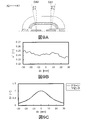
- FIG. 7A is a diagram schematically showing a light emitting element and a light flux controlling member in a surface light source device (herein also referred to as “surface light source device E1”) having the same configuration as that of the surface light source device 100.
- FIG. 7B is a graph showing the relationship between the position in the X direction of the central portion of the surface light source device E1 in the Z direction and the chromaticity of light that illuminates the cover.
- FIG. 7C shows the position in the X direction of the central portion in the Z direction of the light flux controlling member of the surface light source device E1 and the illuminance at the cover of the emitted light derived from each of the first and second light emitting elements from the emitting portion. It is a graph which shows the relationship. The illuminance is expressed as a ratio when the maximum illuminance is 1.
- the length of each light emitting element in the X direction is 2.5 mm
- the pitch between the light emitting elements is 7 mm
- the optical distance OD is 20 mm.
- Both the length in the X direction of the plane portion and the emission portion are 7 mm, and both ends thereof are in contact with the optical axes OA1 and OA2.
- dx represents the distance (mm) from the center in the X direction of the light flux controlling member E1
- the first light emitting element (X1 direction) side is positive and the second light emitting element (X2 direction) side from the center. Expressed negative.
- Er represents the ratio of the illuminance to the maximum illuminance at the cover (irradiated surface) of the emitted light of each light emitting element.
- the broken line represents the illuminance ratio of outgoing light (magenta light) from the first light emitting element, and the solid line represents the illuminance ratio of outgoing light (green light) from the second light emitting element.
- the relationship between the emission angle of the emitted light of the 1st light emitting element and the 2nd light emitting element, and the luminous intensity is shown in FIG.
- the angle of the emission angle is displayed with the first light emitting element side being positive and the second light emitting element side being negative.
- the distance between the optical axes OA1 and OA2 the length of the emitting portion, and the length of the flat portion are all the same.
- the aforementioned C1 is clearly on the X2 direction side than C2.
- the above-mentioned C3 and C4 overlap. Therefore, the above IA and IB are also equal, and the ratio thereof is 1. Therefore, as shown in FIG.
- the difference in chromaticity u ′ in the X direction is sufficiently small.
- the illuminance of the light of each light emitting element in the cover exhibits a distribution having a peak slightly outside the center in the X direction. In the case of such an illuminance distribution, it can be seen that the light reaching the cover from the emitting portion appears to be sufficiently mixed in color.
- FIG. 9A is a diagram schematically showing an emission angle of emitted light of the light emitting element in the light flux controlling member of the surface light source device E2.
- FIG. 9B is a graph showing the relationship between the position in the X direction of the central portion of the surface light source device E2 in the Z direction and the chromaticity of light that illuminates the cover.
- FIG. 9C shows the position in the X direction of the central portion in the Z direction of the light flux controlling member of the surface light source device E2 and the illuminance at the cover of the emitted light derived from each of the first and second light emitting elements from the emitting portion. It is a graph which shows the relationship.
- the length of the emitting portion and the length of the flat portion are both longer than the distance between the optical axes OA1 and OA2, but the above-mentioned C1 is on the X2 direction side with respect to C2. It is clear.
- the above-mentioned C4 is located outside C3, but the difference is 10 °. According to FIG. 8, the light intensity of 10 ° in each light emitting element has almost no difference with respect to the peak value of light intensity, and thus the ratio of IA and IB is approximately 1. Therefore, as shown in FIG. 9B, the difference in chromaticity u ′ in the X direction is sufficiently small.
- the illuminance of the light of each light emitting element in the cover has a peak at substantially the center in the X direction, but the skirt has a distribution slightly shifted far away. It can be seen that even in such an illuminance distribution, the light reaching the cover from the emitting portion appears to be sufficiently mixed in color.
- the cover is illuminated with white light in which two colors of light from the light emitting elements are appropriately mixed. Therefore, the white light is emitted from the cover, and both the surface light source devices E1 and E2 function as an illumination device that emits white light in a planar shape.
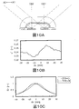
- FIG. 10A is a diagram schematically showing the emission angle of the emitted light of the light emitting element in the light flux controlling member of the surface light source device C1.
- FIG. 10B is a graph showing the relationship between the position in the X direction of the central portion of the surface light source device C1 in the Z direction of the light flux controlling member and the chromaticity of light that illuminates the cover.
- FIG. 10C shows the position of the surface light source device C1 in the X direction of the central portion of the light flux controlling member in the Z direction, and the illuminance at the cover of the emitted light derived from each of the first and second light emitting elements from the emitting portion. It is a graph which shows the relationship.
- the surface light source device C1 is configured in the same manner as the surface light source device E1 except that the light flux controlling member does not have a flat surface portion and an emission portion.
- the light emitted in all directions from each of the first and second light emitting elements is mainly guided in the Z direction in the total reflection portion, but the remaining light is The light distribution in the X direction is emitted from a slight valley between the total reflection portions without being controlled.
- the light emitted from the first light emitting element and the second light emitting element are not restricted in the X direction, the light emitted from the first light emitting element is farther in the X1 direction than the light emitted from the second light emitting element.
- the light emitted from the second light emitting element reaches farther in the X2 direction than the light emitted from the first light emitting element. That is, in the surface light source device C1, the aforementioned point C2 on the inner surface of the cover is farther than C1, and C3 exists but C4 does not exist.
- the light emitted from the first light emitting element has a stronger influence on the first light emitting element side than the center of the light flux controlling member, and is more than the center of the light flux controlling member.
- the light emitted from the second light emitting element has a stronger influence.
- the cover is illuminated by each of the two colors of light from the light emitting element, and the color unevenness due to the two colors of light occurs in the cover at a portion corresponding to the central portion in the Z direction of the light flux controlling member. To do.
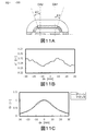
- FIG. 11A is a diagram schematically showing an emission angle of emitted light from the light emitting element and the light flux controlling member in the surface light source device E3.
- FIG. 11B is a graph showing the relationship between the position in the X direction of the central portion in the Z direction of the light flux controlling member in the surface light source device E3 and the chromaticity of light that illuminates the cover.
- FIG. 11C shows the position in the X direction of the central portion in the Z direction of the light flux controlling member in the surface light source device E3, and the illuminance on the cover of the emitted light derived from each of the first and second light emitting elements from the emitting portion. It is a graph which shows the relationship.
- the length of the emitting portion and the length of the flat portion are both longer than the distance between the optical axes OA1 and OA2, but the above-mentioned C1 is on the X2 direction side with respect to C2. It is clear.
- the aforementioned C4 is located outside C3, and the difference is 20 °. According to FIG. 8, the luminous intensity of 20 ° in each light emitting element has a difference with respect to the peak value of luminous intensity.
- the chromaticity u ′ slightly increases or decreases in the X direction, but the difference in the chromaticity u ′ in the X direction is sufficiently small.
- the illuminance of the light of the first light emitting element is shifted to the X1 direction side, and the illuminance of the light of the second light emitting element is shifted to the X2 direction side. Therefore, it can be seen that in the surface light source device E3, it appears that there is some color unevenness in the portion corresponding to the emitting portion in the cover.
- the illumination device is arranged side by side in the X direction, the light emission colors thereof are different from each other, and the optical axis OA1 along the Y direction orthogonal to the X direction, First light emitting element 120a and second light emitting element 120b each having OA2, light flux controlling member 130 covering first light emitting element 120a and second light emitting element 120b from the Y direction, and position away from light flux controlling member 130 in the Y direction And a cover 150 disposed on the surface.
- the light flux controlling member 130 covers the first light emitting element 120a and the second light emitting element 120b from the Y direction away from them, and an incident part 131 for making the emitted light of the first light emitting element 120a and the second light emitting element 120b incident,
- the first light emitting element 120a and the first light emitting element 120a and the first reflection element of the total reflection part for totally reflecting a part of the light incident on the part 131 toward the Z direction orthogonal to the X direction and the Y direction, and the total reflection part in the Z direction.
- An emission part 138 which is disposed at a position adjacent to the ends of the two light emitting elements 120b on the optical axes OA1 and OA2, and emits another part of the light incident from the incidence part 131 outward; and the total reflection part Extends in the Z direction from the end opposite to the optical axes OA1 and OA2 in the Z direction, guides the incident light in the Z direction, and exits in the X direction and the Y direction, that is, outward of the light flux controlling member 130. And a order of the light guide portion 136.
- the intersection of one of the first light emitting element 120a and the second light emitting element 120b and the optical axis is defined as A1.
- a portion of the other light-emitting element of the first light-emitting element 120a and the second light-emitting element 120b on the one light-emitting element side in the X direction is a portion through which the emitted light of the one light-emitting element passes in the emission portion 138
- B1 is the end on the other light emitting element side in the X direction
- the portion of the emission part 138 on the opposite side to the one light emitting element in the X direction in the portion through which the emitted light of the other light emitting element passes is
- the number of the emitting portions 138 can be one per light flux controlling member 130, and the number of the incident portions 131 can be one per light flux controlling member 130.
- the fact that the emission part 138 is formed of a concave curved surface that is recessed in the light emission direction constitutes the emission part 138 with the total reflection parts as continuous connection parts, and is a discontinuous connection part. This is more effective from the viewpoint of preventing defective light emission such as bright lines and dark lines in the cover 150 caused by the above.
- the illumination device further includes the light scattering member 140 that covers the emitting portion 138 from the Y direction from the viewpoint of increasing the light intensity and color uniformity in the cover 150.
- the intersection of the optical axis of the one light emitting element and the cover 150 is C3, the intersection of the other light emitting element and the optical axis is A3, and the emitted light of the one light emitting element in the emission unit 138 Of the X-direction side in the X direction of the portion through which the straight line passes through B3, A1 and B3 and the intersection of the cover 150 with C4, the light intensity I1 of the light from the one light emitting element heading from A1 to C3
- the ratio I1 / I2 to the luminous intensity I2 of the light from the other light emitting element going from A3 to C3 is IA
- the luminous intensity I3 of the light from the one light emitting element going from A1 to C4 is directed from A3 to C4.
- IA is 0.9 to 1.1 times IB. It is more effective and more from the viewpoint of suppressing color unevenness in a portion emitting the light reaches.
- the positions of both ends of the emitting portion 138 in the X direction are the optical axes OA1 of the first light emitting element 120a and the second light emitting element 120b. If the position is OA2 or more, the C1 can be positioned on the outer side in the X direction than the C2, regardless of the length of the optical distance.
- the illumination device according to the second embodiment of the present invention is substantially the same as the first embodiment described above except that it has a light beam control member 230 instead of the light beam control member 130.
- the light flux controlling member 230 will be described.
- FIG. 12A is a perspective view from the front side of the light flux controlling member in the second embodiment
- FIG. 12B is a perspective view from the back side of the light flux controlling member
- 13A is a front view of the light flux controlling member
- FIG. 13B is a plan view of the light flux controlling member
- FIG. 13C is a bottom view of the light flux controlling member
- FIG. 13D is the light flux controlling member. It is a side view of a control member.
- 14A is a diagram showing a cross section of the light flux controlling member taken along line AA in FIG. 13B
- FIG. 14B is a diagram showing a cross section of the light flux controlling member taken along line BB in FIG. 13B. is there.
- the light flux controlling member 230 includes a first incident portion 231a, a second incident portion 231b, a first total reflection portion 235a, a second total reflection portion 235b, a first emission portion 238a, a second emission portion 238b, and a light guide portion 236. Have.
- Both the first incident portion 231a and the second incident portion 231b are concave portions formed in the central portion in the Z direction of the bottom surface of the light flux controlling member 230.
- the first incident portion 231a is disposed on the X1 direction side in the X direction of the central portion, and the second incident portion 231b is disposed on the X2 direction side.
- the planar shape of the opening of the first incident portion 231a is a hexagon.
- a V-shaped groove 232 is formed on the diagonal line of the first incident portion 231a opposite to the X direction in the hexagon.
- the second incident portion 231b is configured similarly to the first incident portion 231a.
- the first total reflection portion 235a is disposed on one side of the center of the light flux controlling member 230 in the Z direction, and the second total reflection portion 235b is disposed on the other side.
- Each of the total reflection portions has a shape in which the distance to the light emitting element in the Y direction gradually increases as the distance from the light emitting element toward one or the other in the Z direction is larger than the YZ plane passing through the center in the X direction. It has a plane-symmetric shape, and has a trough formed at the boundary between two convex curved surfaces at the center. More specifically, each of the total reflection portions has a shape in which the centers of two hemispherical surfaces arranged in parallel are brought close to each other at a distance less than the radius and combined. Both total reflection parts are connected in the Z direction, and a trough is formed at the boundary.
- each of the first emission part 238a and the second emission part 238b is independently arranged so as to protrude from a trough at the boundary (along the X direction) of the first total reflection part 235a and the second total reflection part 235b.
- each of the emission portions is a mountain-shaped section formed by a YZ plane formed by a top edge along the boundary and slopes inclined from the top edge to both sides in the Z direction. .
- the first emission part 238a is arranged so that the center in the X direction is located on the X2 direction side of the optical axis OA1 of the first light emitting element 120a, and the second emission part 238b is The center in the X direction is arranged so as to be located on the X1 direction side with respect to the optical axis OA2 of the second light emitting element 120b.
- the light guide portion 236 is a portion extending along the Z direction from each of the total reflection portions.
- Each of the light guide portions 236 has a semi-cylindrical outer surface and an inner surface that is a shallow concave portion having a shorter length in the Y direction than the length in the X direction on the XY plane. More specifically, the outer surface has such a shape that the central axes of two parallel semicircular bodies are brought close to each other at a distance less than the radius thereof, and the boundary of the combined semicylindrical bodies It has the trough part formed.
- the light flux controlling member 230 further includes a protrusion 239 that protrudes from the side edge in the X direction toward the Y direction (on the side opposite to the emitting portion).
- the protrusion 239 is a member for determining the position of the light flux controlling member 230 with respect to the substrate 110, for example, a member that fits into a positioning hole formed in the substrate 110.
- the light flux controlling member 230 includes the first light emitting element 120a and the first light emitting element 120a of the second light emitting element 120b arranged side by side in the X direction on the substrate 110 as the first incident portion 231a and the second light emitting element 120b as the first light emitting element 120b. It arrange
- the light scattering member 140 is disposed at a position where the diffuse transmitting portion 142 covers both the first light emitting portion 238a and the second light emitting portion 238b of the light flux controlling member 230, and further on the substrate 110.
- the cover 150 is disposed on the illuminating device (surface light source device).
- each of the first light emitting element 120a and the second light emitting element 120b enters the light flux controlling member 230 at the first incident part 231a and the second incident part 231b.
- the light incident on the first incident portion 231a and the second incident portion 231b is basically the first total reflection.
- the light is totally reflected by the portion 235a or the second total reflection portion 235b, and emitted from the surface of the light guide portion 236 while being partially reflected on the surface.
- the light incident on the portion other than the portion corresponding to the emitting portion is guided in the Z direction, intersects the X direction and the Y direction, and is emitted mainly from the light guiding portion 236 to the outside.
- the light is transmitted through the main body 141, and the region outside the portion of the cover 150 corresponding to the central portion in the Z direction of the light flux controlling member 230 is uniformly illuminated, and is observed as white light.
- magenta light of the first light emitting element 120a is emitted from the first light emitting element 238a
- green light of the second light emitting element 120b is emitted from the light incident on the part corresponding to the light emitting part of the light incident part.
- the light is emitted from the second emission part 238b.
- the emitted light from these emission parts is transmitted and diffused through the diffusion transmission part 142 of the light scattering member 140, and reaches a part of the cover 150 corresponding to the central part in the Z direction of the light flux control member 130.
- FIG. 15A is a diagram schematically showing an emission angle of emitted light of the light emitting element and the light flux controlling member in the surface light source device of the present embodiment.
- FIG. 15B shows the position in the X direction of the central portion in the Z direction of the light flux controlling member in the single surface light source device (also referred to as “surface light source device E4”) in the present embodiment, and the first and second light emission from the emitting portion. It is a graph which shows the relationship with the illumination intensity in the cover of the emitted light originating in each of an element.
- 15C shows the position in the X direction of the central portion in the Z direction of the light flux controlling member in the other surface light source device (also referred to as “surface light source device E5”) in the present embodiment, and the first and first positions from the emitting portion. It is a graph which shows the relationship with the illumination intensity in the cover of the emitted light originating in each of 2 light emitting elements.
- one end on the outer side (X1 direction side) in the X direction of the first emitting portion 238a passes through the light emission center of the first light emitting element 120a and is a straight line representing an angle of 10 ° outward with respect to the optical axis OA1. It is in a position that overlaps.
- one end on the inner side (X2 direction side) in the X direction of the first emitting portion 238a passes through the light emission center of the first light emitting element 120a and is at a position where a straight line representing an angle of 30 ° overlaps the optical axis OA1. is there.
- one end on the inner side (X1 direction side) in the X direction of the second emission part 238b overlaps with a straight line that passes through the emission center of the second light emitting element 120b and represents an emission angle of 30 ° inward with respect to the light source OA2.
- One end on the outer side (X2 direction side) passes through the light emission center of the second light emitting element 120b and overlaps with a straight line representing an emission angle of 10 ° outward with respect to the optical axis OA2.
- the cover of the surface light source device E4 is disposed at a position having a sufficiently long optical distance (for example, 20 mm) in the Y direction. Therefore, an unillustrated intersection C1 between the straight line L1 passing through A1 and B1 and the cover in FIG. 15A and an unillustrated intersection C2 between the straight line L2 passing through A2 and B2 and the cover is outside of the X direction (X2). Located on the direction side). Further, although the above-mentioned C4 in the surface light source device E4 is located outside C3, the difference is 10 °. Therefore, the ratio of IA and IB in the surface light source device E4 is the same as that of the surface light source device E2. Similarly, it is almost 1.
- the difference in chromaticity u ′ in the X direction is sufficiently small, and as shown in FIG. 15B, the illuminance of light of each light emitting element in the cover has a distribution having a peak slightly far from the center in the X direction.
- the surface light source device E5 is configured in the same manner as the surface light source device E4, except that the inner ends in the X direction of both emission portions are located at positions where straight lines representing an angle of 35 ° overlap with the respective optical axes. ing. Also in the surface light source device E5, C1 is located on the outer side in the X direction with respect to C2, and C4 is located on the outer side with respect to C3. However, the light intensity ratios in C3 and C4 can be regarded as almost the same. The ratio of IB and IB is approximately 1. Therefore, the difference in chromaticity u ′ in the X direction is sufficiently small, and as shown in FIG. 15C, the illuminance of light of each light emitting element in the cover has a distribution having a peak slightly far from the center in the X direction. Presents.
- the cover is illuminated with white light in which two colors of light from the light emitting elements are appropriately mixed. Therefore, the white light is emitted from the cover, and both the surface light source devices E4 and E5 function as an illumination device that emits white light in a planar shape.
- the emission unit emits the first emission unit for emitting the emission light of the first light emitting element and the emission light of the second light emission element.
- the illuminating device in the third embodiment of the present invention is substantially the same as the first embodiment described above except that it has a light flux control member 330 instead of the light flux control member 130.
- the light flux controlling member 330 will be described.
- FIG. 16A is a perspective view from the front side of the light flux controlling member in the third embodiment
- FIG. 16B is a perspective view from the back side of the light flux controlling member
- 17A is a bottom view of the light flux controlling member
- FIG. 17B is a view showing a cross section of the light flux controlling member taken along line BB in FIG. 17A
- FIG. 17B is a diagram of the light flux controlling member. It is a figure which shows the cross section along CC line in FIG. 17A.
- the light flux controlling member 330 is configured in the same manner as the light flux controlling member 130 except that it has a first incident portion 331a and a second incident portion 331b instead of the incident portion 131.
- the first incident portion 331a includes a predetermined position in the X direction, for example, a first incident surface portion 333a formed on the inner side (X2 direction side) from the center in the X direction of the first incident portion 331a, and the outer side (X1 direction side). It is comprised similarly to the 1st incident part 231a in 2nd Embodiment except including the V-shaped groove
- the second incident portion 331b is, for example, a second incident surface portion 333b formed on the inner side (X1 direction side) from the center in the X direction, and a V-shaped groove 332 formed on the outer side (X2 direction side).
- the configuration is the same as that of the second incident portion 231b in the second embodiment except that the second incident portion 231b is included.
- the emission part is configured the same as that of the first light flux controlling member 130.
- the first incident surface portion 333a and the second incident surface portion 333b are portions in which the V-shaped groove 332 is filled with the above-described resin material, and the surfaces of the first incident surface portion 333a and the second incident surface portion 333b are opposite sides of the V-shaped groove 332 in the YZ plane. This is the part represented by a straight line.
- the first incident surface portion 333 a and the second incident surface portion 333 b have the same function as the flat surface portion 133 of the light flux controlling member 130.
- FIG. 18 is a diagram schematically showing the exit angle of the emitted light of the light emitting element in the light flux controlling member 330.
- B ⁇ b> 1 and B ⁇ b> 2 described above overlap as in the light beam control member 130.
- the intersection C1 (not shown) between the straight line L1 and the cover in FIG. 18 is more outward in the X direction (X2 direction side) than the intersection C2 (not shown) between the straight line L2 and the cover.
- the above-described C3 and C4 overlap as in the above-described surface light source device E1
- the above-described IA and IB are equal, and the ratio thereof is 1.
- the illumination device of the present embodiment exhibits chromaticity u ′ having a sufficiently small difference in the X direction as shown in FIG. 7B, and the light of each light emitting element in the cover.
- the illuminance of has a distribution having a peak slightly far from the center in the X direction.
- a cover is illuminated by the white light which two colors of light from a light emitting element mixed appropriately. Therefore, the white light is emitted from the cover, and the illumination device functions as an illumination device that emits white light in a planar shape.
- the illumination device in the present embodiment can also satisfy the conditions of the emitted light and the luminous intensity described in the first embodiment, and, similarly to the illumination devices according to the first and second embodiments, a light emitting element Therefore, uniform surface light emission is possible without the need for individual adjustment.
- the illumination device is substantially the same as the first embodiment described above except that the light beam control member 430 is provided instead of the light beam control member 130.
- the light flux controlling member 430 has a first emitting part 438a and a second emitting part 438b instead of the emitting part 138, and the incident part includes a first flat part 433a and a second flat part 433b corresponding thereto.
- the light beam control member 130 is configured in the same manner.
- the first emission part 438a and the second emission part 438b are formed by forming a trough in the central part of the emission part 138, so that the first light emitting element 120a side (that is, the first emission part 438a) and the second light emitting element are formed. It has the same configuration as that of the case where it is divided into the portion on the 120b side (that is, the second emitting portion 438b).
- the first flat surface portion 433a and the second flat surface portion 433b also have the same configuration as the case where the flat surface portion is divided by forming a V-shaped groove in the central portion of the flat surface portion 133.
- the first emitting portion 438a is disposed at a position where the end of the first emitting portion 438a overlaps with the optical axis OA1 of the first light emitting element and a straight line having an angle of 30 ° inward with respect to the optical axis OA1 in the X direction.
- the second emission part 438b is disposed at a position where the end thereof overlaps with the optical axis OA2 of the second light emitting element and a straight line forming an angle of 30 ° inward with respect to the optical axis OA2 in the X direction. .
- the first flat surface portion 433a is disposed at a position overlapping the first light emitting portion 438a in the Y direction
- the second flat surface portion 433b is disposed at a position overlapping the second light emitting portion 438b in the Y direction.
- FIG. 19A is a diagram schematically showing an emission angle of emitted light of the light emitting element and the light flux controlling member in one illumination device (also referred to as “surface light source device E6”) in the present embodiment.
- FIG. 19B is a graph showing the relationship between the position in the X direction of the central portion in the Z direction of the light flux controlling member in the surface light source device E6 and the chromaticity of light that illuminates the cover.
- FIG. 19C is a graph showing the relationship between the position in the X direction of the central portion in the Z direction of the surface light source device E6 and the illuminance at the cover of the emitted light derived from each of the first and second light emitting elements from the emitting portion. It is.
- the above-described C3 and C4 overlap as in the above-described surface light source device E1, so that the above IA and IB are equal, and the ratio thereof is 1.
- the surface light source device E6 similarly to the surface light source device E1, the surface light source device E6 exhibits a chromaticity u ′ whose difference in the X direction is sufficiently small as shown in FIG. 19B, and each of the covers as shown in FIG. 19C.
- the illuminance of light of the light emitting element exhibits a distribution having a peak slightly far from the center in the X direction.
- the cover is illuminated with white light in which two colors of light from the light emitting elements are appropriately mixed. Therefore, the white light is emitted from the cover, and the surface light source device E6 functions as an illumination device that emits white light in a planar shape.
- FIG. 20A is a diagram schematically showing an emission angle of emitted light of the light emitting element and the light flux controlling member in another illumination device (also referred to as “surface light source device E7”) of the present embodiment.
- FIG. 20B is a graph showing the relationship between the position in the X direction of the central portion in the Z direction of the light flux controlling member in the surface light source device E7 and the chromaticity of light that illuminates the cover.
- FIG. 20C shows the position in the X direction of the central portion in the Z direction of the light flux controlling member in the surface light source device E7, and the illuminance on the cover of the emitted light derived from each of the first and second light emitting elements from the emitting portion. It is a graph which shows a relationship.
- the position and the size in the X direction of the first emission part 438a, the second emission part 438b, the first plane part 433a, and the second plane part 433b in the light flux controlling member 430 are the same as those in the surface light source apparatus E6. Except for these differences, the configuration is the same as that of the surface light source device E6.
- the first emitting portion 438a has an end that extends in the X direction through the light emission center of the first light emitting element and forms an angle of about 10 ° outward with respect to the optical axis OA1. It is arranged at a position overlapping with a straight line forming an angle of about 40 °.
- the second emitting portion 438b has a straight line whose end passes through the light emission center of the second light emitting element in the X direction and forms an angle of 10 ° on the outside with respect to the optical axis OA2, and a straight line that forms an angle of 40 ° on the inside. It is arranged at the position that overlaps.
- the first flat surface portion 433a is disposed at a position overlapping the first light emitting portion 438a in the Y direction
- the second flat surface portion 433b is disposed at a position overlapping the second light emitting portion 438b in the Y direction.
- the above-described C1 is located on the X2 direction side with respect to C2.
- the above-mentioned C4 is located outside C3.
- the straight line connecting C3 and the light emission center of the first light emitting element, and C4 and the first light emitting element Since the angle formed with the straight line connecting the emission center is 10 °, the ratio of IA and IB is approximately 1. Therefore, as shown in FIG. 20B, the difference in chromaticity u ′ in the X direction is sufficiently small.
- the illuminance of light of each light-emitting element has a distribution with a peak at a substantial center in the X direction, but its base is slightly shifted far away.
- the cover is illuminated with white light in which two colors of light from the light emitting elements are appropriately mixed, and the white light is emitted from the cover.
- the surface light source device E7 also functions as an illumination device that emits white light in a planar shape.
- the illumination device in the present embodiment has a configuration in which the incident portion and the emission portion are substantially independent corresponding to the light emitting elements.
- the incident part and the emission part may be configured substantially independently corresponding to the light emitting elements, and the incident part covers both the first light emitting element and the second light emitting element from the viewpoint of mold manufacture and molding. You may comprise as one dent.
- the first light-emitting element and the second light-emitting element are elements that emit two colors of light that exhibit white color by mixing colors, but the emission colors of both light-emitting elements are other than white by color mixing. It is also possible to appropriately select from combinations that exhibit the desired color. In addition, even when the final color of the emitted light is white, the light emission color of both light emitting elements should be appropriately selected from the combination of colors complementary to each other, other than the combination of magenta and green. Is possible. Furthermore, even if elements that emit white light having different colors are used for the first light emitting element and the second light emitting element, the uniform white covering without color unevenness can be obtained without adjusting the variation in the color. An irradiated surface can be obtained.
- the incident part and the emission part may be independent for each light emitting element or may be common to both light emitting elements.
- one of the incident portion and the emission portion may be configured independently for each light emitting element, and the other may be configured common to both light emitting elements.
- the shape of the emission part can be appropriately determined from the shape of emitting the light that has reached the emission part without being totally reflected, and may be the concave curved surface or the convex slope described above.
- the shape may be a concave or convex portion or a flat surface.
- each surface light source device further includes a light scattering member in addition to the light flux controlling member.
- the lighting device may not have a light scattering member.
- a light flux control member having a light emitting portion with a convex portion such as the light flux control member of the second embodiment, may be able to mix colors with good emission colors without having a light scattering member.
- the surface light source device is specifically described as the illumination device, but the form of the illumination device can be appropriately selected according to the application.
- the shape of the cover may be a cylindrical shape, or may be a shape in which a part of the cylinder is cut out.
Landscapes
- Engineering & Computer Science (AREA)
- General Engineering & Computer Science (AREA)
- Non-Portable Lighting Devices Or Systems Thereof (AREA)
- Planar Illumination Modules (AREA)
- Liquid Crystal (AREA)
Abstract
光束制御部材は、X方向に並んで配置される互いに異なる色の光を出射する第1発光素子および第2発光素子の出射光が、X方向およびそれに直交するZ方向に拡げるとともに、両方向に直交するY方向に向けて拡がるように、上記出射光の配光を制御する。光束制御部材は、特に、両発光素子の直上において、それぞれの発光素子の出射光が、X方向における特定の範囲に到達するように、上記出射光の配光を制御する。
Description
本発明は、照明装置および光束制御部材に関する。
近年、省エネルギーや環境保全の観点から、発光ダイオード(以下、「LED」ともいう)を光源とする照明装置が使用されている。このような照明装置の例には、光源としてのLEDを有する電球型の照明装置、蛍光管型の照明装置、および、平面上に複数配置されたLEDを光源として有する面光源装置が含まれる。
LEDは、小型であるため、照明装置の大きさや厚みを減らすのに有効である。このため、上記面光源装置は、室内を照らす用途以外にも、液晶のバックライトとして有益である。当該バックライト用の面光源装置には、複数色のLEDを平面方向に規則的に配置してなる面光源装置が知られている。この面光源装置は、LEDの特定の規則的な配置によって局所的な色ムラの発生を抑制している(例えば、特許文献1参照)。
しかしながら、複数色のLEDを配置してなる上記面光源装置では、色または明るさが均一な面発光を実現するためには、LED間のピッチやLEDの配列、個々のLEDの発光強度などの種々の条件の調整を要する場合がある。このため、LEDの個別の調整を要することなく均一な面発光を実現することが、面光源装置には求められている。
本発明の目的は、複数色の発光素子の混色による発光において、発光素子の個別の調整を要さずに均一な発光を実現できる照明装置を提供することである。また、本発明の別の目的は、上記照明装置において使用される光束制御部材を提供することである。
本発明に係る照明装置は、第1の軸に沿う方向に並んで配置されており、それらの発光色が互いに異なり、かつ前記第1の軸に直交する第2の軸に沿う光軸をそれぞれ有する第1発光素子および第2発光素子と、前記第1および第2の発光素子を前記第2の軸に沿う方向から覆う光束制御部材と、前記第2の軸に沿う方向における前記光束制御部材から離れた位置に配置されている拡散部材と、を有する照明装置であって、前記光束制御部材は、前記第1発光素子および前記第2発光素子をこれらから離れて前記第2の軸に沿う方向から覆い、前記第1発光素子および前記第2発光素子の出射光を入射させる入射部と、前記入射部で入射した光の一部を、前記第1の軸および前記第2の軸に直交する第3の軸に沿う方向に向けて全反射させるための全反射部と、前記第3の軸に沿う方向における前記全反射部の、前記第1発光素子および前記第2発光素子の前記光軸側の端に隣接する位置に配置され、前記入射部から入射した光の他の一部を外方へ出射するための出射部と、前記全反射部の前記第3の軸に沿う方向における前記光軸とは反対側の端から前記第3の軸に沿う方向に延出し、入射した光を前記第3の軸に沿う方向に導くとともに外方に出射するための導光部と、を有し、前記照明装置は、前記第1発光素子の光軸および前記第2発光素子の光軸を含む断面において、前記第1発光素子および前記第2発光素子のうちの一方の発光素子とその光軸との交点をA1、前記第1発光素子および前記第2発光素子のうちの他方の発光素子の、前記第1の軸に沿う方向における前記一方の発光素子側の端をA2、前記出射部における前記一方の発光素子の出射光が通る部分のうちの、前記第1の軸に沿う方向における前記他方の発光素子側の端をB1、前記出射部における前記他方の発光素子の出射光が通る部分のうちの、前記第1の軸に沿う方向における前記一方の発光素子とは反対側の端をB2、前記A1と前記B1とを通る直線の前記拡散部材との交点をC1、および、前記A2と前記B2とを通る直線の前記拡散部材との交点をC2、としたときに、前記C1は、前記C2よりも前記第1の軸に沿う方向における外側に位置する。
また、本発明に係る光束制御部材は、上記照明装置に用いられる前記光束制御部材であって、前記出射部および前記入射部は、いずれも一つであり、前記第1の軸に沿う方向において、前記出射部の両端の位置は、前記第1発光素子および前記第2発光素子の光軸の位置かそれ以上離れた位置である。
本発明によれば、複数色の発光素子の混色による発光において、発光素子の個別の調整を要さずに均一な面発光を実現することができる。
以下、本発明の実施の形態について、図面を参照して詳細に説明する。以下の説明では、本発明の照明装置の代表例としての面光源装置の形態にて本発明の実施の形態を説明する。
[第1の実施の形態]
図1Aは、本発明の第1の実施の形態に係る照明装置(面光源装置)を模式的に示す平面図であり、図1Bは、図1A中のB部を拡大して示す図であり、図1Cは、図1A中のC-C線に沿う上記照明装置の断面の要部を拡大して示す図である。
図1Aは、本発明の第1の実施の形態に係る照明装置(面光源装置)を模式的に示す平面図であり、図1Bは、図1A中のB部を拡大して示す図であり、図1Cは、図1A中のC-C線に沿う上記照明装置の断面の要部を拡大して示す図である。
面光源装置100は、基板110と、基板110に配置された複数の発光素子と、基板110上の当該発光素子を覆う位置にそれぞれ配置された複数の光束制御部材130と、個々の光束制御部材上にそれぞれ配置された複数の光散乱部材140と、基板110上であって光束制御部材130から離れた位置に配置されたカバー150とを有する。
基板110は、上記発光素子および光束制御部材130を支持するための部材である。基板110は、面光源装置に通常利用される基板であってよく、上記発光素子のための配線や、入射する光をカバー150に向けて反射、拡散するための光拡散層などを含む。基板110は、X軸に沿う方向(X方向)およびZ軸に沿う方向(Z方向)に所定の間隔で配置された上記発光素子および光束制御部材130を支持している。基板110は、例えば、アルミニウムや銅などの熱伝導性の高い金属で構成される。基板110に高い熱伝導性を要しない場合は、基板110は、ガラス不織布にエポキシ樹脂を含浸させた樹脂製基板のような熱伝導性の比較的低い材料で構成することができる。
なお、本明細書において、X軸(特許請求の範囲における「第1の軸」)およびZ軸(特許請求の範囲における「第3の軸」)は、基板110と平行であり、かつ互いに直交するように設定された仮想の軸である。この後説明するように、一対の発光素子(第1発光素子120aおよび第2発光素子120b)は、X軸に沿う方向に配列されている。また、Y軸(特許請求の範囲における「第2の軸」)は、X軸(第1の軸)およびZ軸(第2の軸)に直交するように設定された仮想の軸である。なお、本明細書では、X軸に沿う方向を単に「X方向」と、Y軸に沿う方向を単に「Y方向」と、Z軸に沿う方向を単に「Z方向」と称することがある。X方向とは、X軸に沿う一方向のみを意味する場合もあるし、X軸に沿う互いに反対向きの二方向を意味する場合もある。Y方向およびZ方向も同様である。
基板110には、第1発光素子120aと、第2発光素子120bとを一対とする、複数対の発光素子が配置されている。たとえば、第1発光素子120aおよび第2発光素子120bは、いずれも、発光ダイオード(LED)である。第1発光素子120aと第2発光素子120bとは、X方向に並んで配置されている。第1発光素子120aおよび第2発光素子120bは、いずれも、Y方向に沿う光軸をそれぞれ有する。
第1発光素子120aおよび第2発光素子120bは、互いに異なる色の光を出射する。ここで、出射光の色が異なるとは、出射光のそれぞれの分光分布が異なることを言う。したがって、出射光が同種の色であっても出射光の色味が異なる場合がある。たとえば、第1発光素子120aの発光色はマゼンタであり、第2発光素子120bの発光色はグリーンである。
光束制御部材130および光散乱部材140については後に説明する。
カバー150は、光束制御部材130から出射された光を出射する部材であり、通常、透光性と光拡散性とを有し、拡散部材とも言われる。カバー150は、例えば樹脂製の平板であり、基板110に対向し、かついずれの光束制御部材130に対してY方向において離れて配置されている。
カバー150の材料の例には、ポリメタクリル酸メチル(PMMA)、ポリカーボネート(PC)、ポリスチレン(PS)、スチレン・メチルメタクリレート共重合樹脂(MS)などの光透過性樹脂、および、光透過性のガラス、が含まれる。カバー150の光拡散性は、常法によってカバー150に付与することができ、例えば、カバー150の表面の粗面化処理によって付与することができ、あるいは、カバー150中にビーズなどの散乱子を分散させることによって付与することが可能である。
次いで、光束制御部材130を説明する。図2Aは、第1の実施の形態における光束制御部材の表側からの斜視図であり、図2Bは、当該光束制御部材の裏側からの斜視図である。また、図3Aは、上記光束制御部材の正面図であり、図3Bは、当該光束制御部材の平面図であり、図3Cは、当該光束制御部材の底面図であり、図3Dは、当該光束制御部材の側面図である。さらに、図4Aは、上記光束制御部材の図3BにおけるA-A線に沿う断面を示す図であり、図4Bは、上記光束制御部材の図3BにおけるB-B線に沿う断面を示す図である。
光束制御部材130は、透光性を有する材料で構成される。当該材料には、前述したカバー150を構成する樹脂材料を利用することができる。光束制御部材130は、例えば、そのような樹脂の一体成形品である。光束制御部材130は、さらに光拡散性を有していてもよく、当該光拡散性も、カバー150のそれと同様の方法により光束制御部材130に付与することが可能である。
光束制御部材130は、その平面形状がZ方向に長い略矩形であり、その表面側の形状は、X方向およびY方向において中央部で括れており、X方向およびZ方向において、それら中心軸に対して各々線対称の形状となっている。また、裏面側の形状は、Z方向における中央部およびX方向における両端部に略H字型の肉厚の部分を有し、その他の部分が薄肉の部分(凹部)となっている。上記中央部のZ方向におけるさらに中心部では、X方向に延出する凹部が形成されている。この凹部は、第1発光素子120aおよび第2発光素子120bを覆う位置および大きさで形成されている。
光束制御部材130は、入射部131、全反射部、出射部138および導光部136を有する。
入射部131は、前述した裏面側の形状における肉厚の部分に形成された凹部の表面である。このように、入射部131は、第1発光素子120aおよび第2発光素子120bをこれらから離れてY方向から覆い、第1発光素子120aおよび第2発光素子120bの出射光を受ける部分となっている。入射部131のX方向およびZ方向における中央部には、平面部133が形成されており、平面部133のX方向における隣には、V字溝132が形成されている。平面部133は、X方向において、第1発光素子120aおよび第2発光素子120bのそれぞれの光軸を含む範囲(例えば、両光軸間)に形成され、後述する出射部138から出射される光を生成するように形成されている。このように入射部131における上記中央部は、本実施の形態においては平面で形成されているが、それに限られない。
上記全反射部は、光束制御部材130の前述した中央部の括れからZ方向に沿って拡大しながら延出する曲面の部分であり、上記括れのZ方向における一方側に配置されている第1全反射部135aと、他方側に配置されている第2全反射部135bとを含む。第1全反射部135aおよび第2全反射部135bの外表面は、共に、上記括れからZ方向に沿って離れるに連れて、Y方向およびX方向における第1発光素子120aおよび第2発光素子120bからの距離が漸次大きくなる形状の凸曲面である。このように、上記全反射部は、入射部131から入射した光の一部を、Z方向に向けて全反射させるように構成されている。
出射部138は、光束制御部材130における上記括れの部分に形成されている。出射部138は、具体的には、Y方向において、第1発光素子120aおよび第2発光素子120bの出射方向(外方)に対して窪む形状を有する曲面で構成されている。より詳しくは、出射部138は、Z方向において第1全反射部135aと第2全反射部135bとを連続して繋ぐ凹曲面の部分である。出射部138の高さ(上記発光素子からのY方向における距離)は、X方向において一定である。
出射部138は、X方向において、第1発光素子120aの光軸および第2発光素子120bの光軸と交わるように配置されている。たとえば、出射部138は、光束制御部材130のZ方向における中心部に配置されており、X方向において平面部133と同じ範囲(すなわち両光軸間)に配置されている。このように、出射部138は、上記全反射部に、Z方向における上記全反射部の上記光軸寄り(中央側)の端で隣接する位置に配置され、入射部131から入射した光の他の一部を外方へ出射するように構成されている。すなわち、出射部138は、出射部138へ到達する光を外方へ出射するような形状であればよく、本実施の形態における形状に限定されない。
導光部136は、上記全反射部からZ方向に沿ってさらに外側(第1発光素子120aの光軸および第2発光素子の光軸からZ方向に沿って離れる方向)へ延出する部分である。導光部136は、半筒状であり、外表面と内表面とを有する。上記外表面は、Z方向に沿って上記全反射部から離れるほどにわずかに収縮する先細りの形状となっている。上記内表面は、Z方向において一定の形状となっている。このように、導光部136は、上記全反射部のZ方向における上記光軸とは反対側の端からZ方向に延出し、入射した光をZ方向に導くとともに導光部136から外方へ出射するように構成されている。
なお、光束制御部材130のZ方向における中央の上記括れの部分は、前述の出射部138を除き、第1全反射部135aの凸曲面とこれに対向する第2全反射部135bの凸曲面との間に形成される谷部で構成されている。
次に、光散乱部材140について説明する。図5Aは、本実施の形態における光散乱部材の正面図であり、図5Bは、上記光散乱部材の底面図であり、図5Cは、上記光散乱部材の側面図であり、図5Dは、上記光散乱部材の図5B中のD-D線に沿う断面図である。
光散乱部材140は、光束制御部材130を覆う本体141と、本体141のZ方向における中央部に配置されている拡散透過部142と、本体141のZ方向における両端部に配置されている係止爪143と、光散乱部材140のZ方向における中央部に配置されている突起144とを有している。
本体141は、光束制御部材130のZ方向における大部分を覆う半筒状の部材である。本体141は、透光性を有していればよく、透明であってもよいし、光拡散性をさらに有していてもよい。本体141は、カバー150および光束制御部材130で前述した各種の材料と同じ材料で構成することができる。
拡散透過部142は、本体141のZ方向における中央部の内周壁面に形成された、X方向に沿って延出している複数の並列する凹条145で構成されている。それぞれの凹条145のYZ平面における断面形状は、例えば半円状である。凹条145の形状は、同一であってもよいし異なっていてもよい。
係止爪143は、光束制御部材130に対する光散乱部材140の位置を決めるための部材であり、例えば、光束制御部材130の表面のZ方向における両端部に形成された係止穴に嵌合する部材である。また、突起144は、基板110に対する光散乱部材140の位置を決めるための部材であり、例えば、基板110に形成される位置決め孔に嵌合する部材である。
光束制御部材130は、基板110においてX方向に並んで配置されている第1発光素子120aおよび第2発光素子120bを入射部131で覆う位置に配置される。このとき、光束制御部材130は、第1発光素子120aおよび第2発光素子120bのそれぞれの光軸が、入射部131および出射部138における所定の位置、例えば入射部131における平面部133および出射部138と交差するように配置される。
光散乱部材140は、基板110上に配置された光束制御部材130に対してY方向から被さって配置される。光散乱部材140は、基板110および光束制御部材130の一方または両方に対して決められた位置に配置され、拡散透過部142は、光束制御部材130の出射部138をY方向において覆う位置に配置される。
こうして、上記発光素子および光束制御部材130を有する発光装置が構成される。さらに基板110上にカバー150が配置されると照明装置(面光源装置100)が構成される。
第1発光素子120aおよび第2発光素子120bのそれぞれの出射光は、入射部131から光束制御部材130に入射する。入射部131に入射した光のうち、平面部133以外の部分に入射した光は、基本的には第1全反射部135aまたは第2全反射部135bで全反射し、そして導光部136の表面から、当該表面において一部反射しながら出射される。こうして、平面部133以外の部分に入射した光は、Z方向に導かれながらX方向およびY方向において交差し、主に導光部136から外方へ出射される。
光散乱部材140で覆われている部分において導光部136から出射された光は、光散乱部材140の本体141を透過し、主に、カバー150において、光束制御部材130のZ方向における中心部に対応する部分よりも外側の領域を一様に照らす。すなわち、カバー150における光束制御部材130に対応する領域とその周辺が導光部136から出射された光による照射領域となるが、光束制御部材130のZ方向における中心部に対応する部分の明るさは導光部136からの出射光以外で補われる。第1発光素子120aのマゼンタ光と第2発光素子120bのグリーン光は、カバー150における光束制御部材130のZ方向における両端部に対応する部分に向かって混色される。その結果、導光部136からの出射光は、白色光として観察される。
入射部131に入射した光のうち、平面部133に入射した光の一部は、出射部138から出射される。出射部138からの出射光は、光散乱部材140の拡散透過部142を拡散されながら透過して、カバー150における光束制御部材130のZ方向における中央部に対応する部分に到達する。平面部133を介して出射部138から出射される光について、さらに説明する。
図6Aは、上記光束制御部材と発光素子との平面視したときの位置関係をその説明のために模式的に示す図であり、図6Bは、発光素子からのXY平面における出射光の出射角を説明するための図である。図6Aに示されるように、上記発光素子の平面形状は正方形であり、上記発光素子の中心は、光束制御部材130の、Z方向における中心を通るX方向に沿う中心軸上にあるものとする。また、上記発光素子の光軸は、上記発光素子から出射される光の光学的な中心を表しており、上記発光素子の平面形状における中心を通る、Y方向に沿う直線で表される。図6B中、OA1は、第1発光素子120aの光軸を表し、OA2は、第2発光素子120bの光軸を表している。また、XY平面における2つのX方向のうち、第2発光素子120bから第1発光素子120aに向かう方向をX1方向、第1発光素子120aから第2発光素子120bに向かう方向をX2方向とする。
出射部138から出射される光については、X方向において、一方の発光素子の中心からの光が、他方の発光素子の内縁(一方の発光素子側の縁)からの光を超えてより遠方まで到達する。すなわち、第1発光素子120aとその光軸OA1との交点をA1、第2発光素子120bのX1方向側の端をA2、出射部138における第1発光素子120aの出射光が通る部分のうちの、X2方向側の端をB1、出射部138における第2発光素子120bの出射光が通る部分のうちの、X2方向側の端をB2、A1とB1とを通る直線L1のカバー150との交点をC1(図6Bにおいて左側の図外にある)、そして、A2とB2とを通る直線L2のカバー150との交点をC2としたときに、C1はC2よりもX2方向側(光軸OA2から離れる方向)に位置する。なお、B1とB2は重複する。
このように、第1発光素子120aおよび第2発光素子120bよりもX2方向側の領域では、より遠い第1発光素子120aの中心からの光は、より近い第2発光素子120bの内縁(X1方向側の縁)からの光よりもより遠方に到達している。図示しないが、同様に、第1発光素子120aおよび第2発光素子120bよりもX1方向側の領域では、第2発光素子120bの中心からの光は、第1発光素子120aの内縁(X2方向側の縁)からの光よりもより遠方に到達する。よって、第1発光素子120aおよび第2発光素子120bのそれぞれからの、出射部138から出射される出射光は、カバー150の内表面において、互いに、そして確実に重なり合う。
さらに、出射部138から出射される光については、X方向において、一方の発光素子の光の光度と他方の発光素子の光の光度との比が、カバー150の内表面の特定の位置間で一定の範囲に入っていることが、両発光素子からの光の混色の均一さを高める観点から好ましい。
すなわち、第1発光素子120aの光軸OA1とカバー150との交点をC3、第2発光素子120bとその光軸OA2との交点をA3、出射部138のX1方向側の端をB3、A1およびB3を通る直線(P3)とカバー150との交点をC4とする。また、A1とC3とを結ぶ直線をP1、A3とC3とを結ぶ直線をP2、A1とC4とを結ぶ直線をP3、A3とC4とを結ぶ直線をP4とする。さらに、A1からC3に向かう(直線P1に沿う)第1発光素子120aからの光の光度をI1、A3からC3に向かう(直線P2に沿う)第2発光素子120bからの光の光度をI2、これらの比I1/I2をIAとし、A1からC4に向かう第1発光素子120aからの光の光度をI3、A3からC4に向かう第2発光素子120bからの光の光度をI4とし、これらの比I3/I4をIB、としたときに、IAは、IBの0.9~1.1倍であることが、上記の観点から好ましい。
このように、第1発光素子120aおよび第2発光素子120bよりもX1方向側の領域では、より近い第1発光素子120aの出射光の光度の、より遠い第2発光素子120bの出射光の光度に対する比が、より近い第1発光素子120aの中心からの光が到達するX方向における範囲のうちの特定の範囲において実質的に等しい。図示しないが、同様に、第1発光素子120aおよび第2発光素子120bよりもX2方向側の領域では、より近い第2発光素子120bの出射光の光度の、より遠い第1発光素子120aの出射光の光度に対する比が、より近い第2発光素子120bの中心からの光が到達するX方向における範囲のうちの特定の範囲において実質的に等しい。
上記のIAおよびIBの関係が満たされると、カバー150における第1発光素子120aの出射光と第2発光素子の120bの出射光との重なる部分における色度差が十分に小さくなり、色ムラが実質的に観察されなくなる。このように、上記の関係が満たされることは、カバー150における光の混色の均一さを高める観点から好ましい。
上記の説明から明らかなように、出射部138からの出射光は、カバー150における光束制御部材130のZ方向における中央部に対応する部分に到達し、光束制御部材130の他の部分からの出射光と同様に白色光として観察される。よって、カバー150は、X方向およびZ方向のいずれにおいても暗部を形成することなく、均一に白色光を外方へ出射する。
上記X方向におけるC1とC2との位置関係、および、上記IAとIBとの関係は、いずれも、発光素子間のX方向における間隔、出射部138のX方向における長さ、平面部133のX方向における長さ、または光学距離、によって調整することが可能である。当該光学距離は、光源から被照射面までの距離であり、例えば、面光源装置100ではY方向における発光素子の設置面からカバー150の内表面までの距離である。たとえば、光学距離は、10~30mmの範囲から適宜に決めることができる。上記の間隔、長さおよび光学距離は、コンピュータによる(例えば、汎用のPCと光学設計用の公知のプログラムとを用いる)シミュレーションおよび試作品による実測の一方または両方によって適宜に予想し、また確認することが可能である。
図7Aは、面光源装置100と同様の構成を有する面光源装置(ここでは「面光源装置E1」とも言う)における発光素子および光束制御部材を模式的に示す図である。図7Bは、面光源装置E1の、当該光束制御部材のZ方向における中心部のX方向における位置とカバーを照らす光の色度との関係を示すグラフである。図7Cは、面光源装置E1の、上記光束制御部材のZ方向における中心部のX方向における位置と、出射部からの、第1、第2発光素子のそれぞれに由来の出射光のカバーにおける照度との関係を示すグラフである。当該照度は、最大照度を1としたときの割合で表されている。
図7Aにおいて、各発光素子のX方向における長さは2.5mmであり、発光素子間のピッチ(X方向における両発光素子の中心間距離)は7mmであり、光学距離ODは20mmである。平面部および出射部のX方向における長さは、ともに7mmであり、その両端で光軸OA1、OA2に接している。図7B中、dxは光束制御部材E1のX方向における中心からの距離(mm)を表し、当該中心よりも第1発光素子(X1方向)側は正、第2発光素子(X2方向)側は負で表される。図7C中、Erは、各発光素子の出射光のカバー(被照射面)における最大照度に対する照度の比を表す。破線は、第1発光素子の出射光(マゼンタ光)の照度比を表し、実線は、第2発光素子の出射光(グリーン光)の照度比を表す。
なお、第1発光素子および第2発光素子の出射光の出射角とその光度との関係を図8に示す。出射角の角度は、第1発光素子側を正、第2発光素子側を負で、それぞれ表示されている。面光源装置E1の光束制御部材では、光軸OA1、OA2間の距離、出射部の長さおよび平面部の長さがいずれも同じである。このため、前述のC1は、C2よりも明らかにX2方向側にある。また、前述のC3とC4とが重なる。よって、上記のIAおよびIBも等しく、これらの比は1となる。よって、図7Bに示されるように、X方向における色度u’の差が十分に小さい。このとき、カバーにおけるそれぞれの発光素子の光の照度は、X方向における中心よりもわずかに外側にピークを有する分布を呈している。このような照度分布の場合に、出射部からカバーに到達した光が十分に混色されて見えることがわかる。
図9Aは、面光源装置E2の、上記光束制御部材における発光素子の出射光の出射角を模式的に示す図である。図9Bは、面光源装置E2の、当該光束制御部材のZ方向における中心部のX方向における位置とカバーを照らす光の色度との関係を示すグラフである。図9Cは、面光源装置E2の、上記光束制御部材のZ方向における中心部のX方向における位置と、出射部からの、第1、第2発光素子のそれぞれに由来の出射光のカバーにおける照度との関係を示すグラフである。
面光源装置E2は、平面部および出射部のX方向における長さがより長い以外は、面光源装置E1と同様に構成されている。より具体的には、出射部および平面部の長さは、いずれも、出射部の端が光軸に対して所定の角度φ1(=10°)をなす直線と接するときの出射部の長さと同じである。
面光源装置E2の光束制御部材では、光軸OA1、OA2間の距離よりも、出射部の長さおよび平面部の長さがいずれも長いが、前述のC1がC2よりもX2方向側にあることは明らかである。また、前述のC4は、C3よりも外側に位置するが、その差は10°である。図8によれば、各発光素子における10°の光度は、光度のピーク値に対してほとんど差を有していないことから、上記のIAおよびIBの比は、ほぼ1となる。よって、図9Bに示されるように、X方向における色度u’の差が十分に小さい。このとき、カバーにおけるそれぞれの発光素子の光の照度は、X方向におけるほぼ中心にピークを有するが、その裾野はわずかに遠方にシフトしている分布を呈している。このような照度分布の場合にも、出射部からカバーに到達した光が十分に混色されて見えることがわかる。
面光源装置E1、E2では、カバーは、発光素子からの二色の光が適切に混色した白色光で照らされる。よって、当該カバーからは当該白色光が出射され、面光源装置E1、E2は、いずれも、白色光を面状に発光する照明装置として機能する。
図10Aは、面光源装置C1の、光束制御部材における発光素子の出射光の出射角を模式的に示す図である。図10Bは、面光源装置C1の、上記光束制御部材のZ方向における中心部のX方向における位置とカバーを照らす光の色度との関係を示すグラフである。図10Cは、面光源装置C1の、上記光束制御部材のZ方向における中心部のX方向における位置と、出射部からの、第1、第2発光素子のそれぞれに由来の出射光のカバーにおける照度との関係を示すグラフである。面光源装置C1は、上記光束制御部材が平面部および出射部を有さない以外は、面光源装置E1と同様に構成されている。
図10Aに示されるように、面光源装置C1では、第1、第2発光素子のそれぞれから全方位に出射された光は、全反射部において主にZ方向へ導かれるが、残りの光は、X方向への配光が制御されないまま、全反射部の間のわずかな谷間から出射される。
第1発光素子および第2発光素子の出射光は、いずれも、X方向において規制されないことから、第1発光素子の出射光は、第2の発光素子の出射光よりもX1方向のより遠方まで到達し、第2発光素子の出射光は、第1の発光素子の出射光よりもX2方向のより遠方まで到達する。すなわち、面光源装置C1では、カバーの内表面における前述の点C2は、C1よりも遠方にあり、C3は存在するもののC4は存在しない。
面光源装置C1では、図10B、図10Cに示されるように、光束制御部材の中心よりも第1発光素子側では第1発光素子の出射光がより強く影響し、光束制御部材の中心よりも第2発光素子側では第2発光素子の出射光がより強く影響している。その結果、カバーは、発光素子からの二色の光のそれぞれによって照らされ、カバーには、光束制御部材のZ方向における中央部に対応する部分において、上記の二色の光による色ムラが発生する。
図11Aは、面光源装置E3における発光素子および光束制御部材の出射光の出射角を模式的に示す図である。図11Bは、面光源装置E3における上記光束制御部材のZ方向における中心部のX方向における位置とカバーを照らす光の色度との関係を示すグラフである。図11Cは、面光源装置E3における上記光束制御部材のZ方向における中心部のX方向における位置と、出射部からの、第1、第2発光素子のそれぞれに由来の出射光のカバーにおける照度との関係を示すグラフである。
面光源装置E3は、平面部および出射部のX方向における長さがより長い以外は、面光源装置E1と同様に構成されている。より具体的には、出射部および平面部の長さは、いずれも、出射部の端が光軸に対して所定の角度φ2(=20°)をなす直線と接するときの出射部の長さと同じである。
面光源装置E3の光束制御部材では、光軸OA1、OA2間の距離よりも、出射部の長さおよび平面部の長さがいずれも長いが、前述のC1がC2よりもX2方向側にあることは明らかである。前述のC4は、C3よりも外側に位置し、その差は20°である。図8によれば、各発光素子における20°の光度は、光度のピーク値に対して差を有している。
面光源装置E3では、図11Bに示されるように、色度u’は、X方向において多少の増減を有するが、X方向における色度u’の差は、十分に小さい。しかしながら、X方向における中心に対して、第1発光素子の光の照度はX1方向側に、第2発光素子の光の照度はX2方向側に、それぞれシフトしている分布を呈している。よって、面光源装置E3では、カバーにおける出射部に対応する部分で若干の色ムラがあるように見えることがわかる。
以上の説明から明らかなように、本実施の形態の照明装置は、X方向に並んで配置されており、それらの発光色が互いに異なり、かつX方向に直交するY方向に沿う光軸OA1、OA2をそれぞれ有する第1発光素子120aおよび第2発光素子120bと、第1発光素子120aおよび第2発光素子120bをY方向から覆う光束制御部材130と、Y方向における光束制御部材130から離れた位置に配置されているカバー150とを有する。光束制御部材130は、第1発光素子120aおよび第2発光素子120bをこれらから離れてY方向から覆い、第1発光素子120aおよび第2発光素子120bの出射光を入射させる入射部131と、入射部131で入射した光の一部を、X方向およびY方向に直交するZ方向に向けて全反射させるための全反射部と、Z方向における上記全反射部の、第1発光素子120aおよび第2発光素子120bの光軸OA1、OA2側の端に隣接する位置に配置され、入射部131から入射した光の他の一部を外方へ出射するための出射部138と、上記全反射部のZ方向における上記光軸OA1、OA2とは反対側の端からZ方向に延出し、入射した光をZ方向に導くとともにX方向およびY方向、すなわち光束制御部材130の外方に出射するための導光部136とを有する。そして、X方向およびY方向を含むXY平面(光軸OA1およびOA2を含む断面)において、第1発光素子120aおよび第2発光素子120bのうちの一方の発光素子とその光軸との交点をA1、第1発光素子120aおよび第2発光素子120bのうちの他方の発光素子の、X方向における上記一方の発光素子側の端をA2、出射部138における上記一方の発光素子の出射光が通る部分のうちの、X方向における上記他方の発光素子側の端をB1、出射部138における上記他方の発光素子の出射光が通る部分のうちの、X方向における上記一方の発光素子とは反対側の端をB2、A1とB1とを通る直線のカバー150との交点をC1、および、A2とB2とを通る直線のカバー150との交点をC2、としたときに、C1は、C2よりもX方向における外側に位置する。本実施の形態では、上記B2はB1と重複している。上記の構成を有することにより、上記照明装置は、複数色の発光素子の混色による発光において、発光素子の個別の調整を要さずに均一な発光を実現することができる。
上記照明装置において、出射部138は、一つの光束制御部材130当たり一つとすることが可能であり、また、入射部131も、一つの光束制御部材130当たり一つとすることが可能である。
また、出射部138が、その光の出射方向に対して凹んでいる凹曲面で構成されていることは、全反射部同士を連続した接続部として出射部138を構成し、不連続な接続部によって生じるカバー150における輝線や暗線などの不良発光を防止する観点からより一層効果的である。
また、上記照明装置が、出射部138をY方向から覆う光散乱部材140をさらに有することは、カバー150における光の強度および色の均一性を高める観点からより一層効果的である。
また、XY平面において、上記一方の発光素子の光軸とカバー150との交点をC3、上記他方の発光素子とその光軸との交点をA3、出射部138における上記一方の発光素子の出射光が通る部分のうちの、X方向におけるX1方向側の端をB3、A1およびB3を通る直線とカバー150との交点をC4、A1からC3に向かう上記一方の発光素子からの光の光度I1の、A3からC3に向かう上記他方の発光素子からの光の光度I2に対する比I1/I2をIA、および、A1からC4に向かう上記一方の発光素子からの光の光度I3の、A3からC4に向かう上記他方の発光素子からの光の光度I4に対する比I3/I4をIB、としたときに、IAがIBの0.9~1.1倍であることは、カバー150における出射部138から出射した光が到達する部分での色ムラを抑制する観点からより一層効果的である。
また、光束制御部材130では、出射部138および入射部131がいずれも一つであり、X方向において、出射部138の両端の位置が第1発光素子120aおよび第2発光素子120bの光軸OA1、OA2の位置かそれ以上離れた位置であると、上記光学距離の長短に関わらず、上記C1をC2よりもX方向における外側に位置させることが可能となる。
[第2の実施の形態]
本発明の第2の実施の形態における照明装置は、光束制御部材130の代わりに光束制御部材230を有する以外は、前述した第1の実施の形態と実質的に同じである。以下、光束制御部材230について説明する。
本発明の第2の実施の形態における照明装置は、光束制御部材130の代わりに光束制御部材230を有する以外は、前述した第1の実施の形態と実質的に同じである。以下、光束制御部材230について説明する。
図12Aは、第2の実施の形態における光束制御部材の表側からの斜視図であり、図12Bは、当該光束制御部材の裏側からの斜視図である。また、図13Aは、上記光束制御部材の正面図であり、図13Bは、当該光束制御部材の平面図であり、図13Cは、当該光束制御部材の底面図であり、図13Dは、当該光束制御部材の側面図である。さらに、図14Aは、上記光束制御部材の図13BにおけるA-A線に沿う断面を示す図であり、図14Bは、上記光束制御部材の図13BにおけるB-B線に沿う断面を示す図である。
光束制御部材230は、第1入射部231a、第2入射部231b、第1全反射部235a、第2全反射部235b、第1出射部238a、第2出射部238b、および導光部236を有する。
第1入射部231aおよび第2入射部231bは、ともに、光束制御部材230の底面のZ方向における中央部に形成された凹部である。第1入射部231aは、当該中央部のX方向におけるX1方向側に配置されており、第2入射部231bは、X2方向側に配置されている。第1入射部231aの開口部の平面形状は、六角形である。第1入射部231aの当該六角形におけるX方向に対向する角の対角線上には、V字溝232が形成されている。第2入射部231bも、第1入射部231aと同様に構成されている。
第1全反射部235aは、光束制御部材230のZ方向の中心よりも一方側に配置されており、第2全反射部235bは、他方側に配置されている。いずれの全反射部も、Z方向の一方または他方に向けて発光素子から離れるほどにY方向における発光素子までの距離が漸次大きくなる形状であって、X方向の中心を通るYZ平面に対して面対称な形状を有しており、当該中心には、二つの凸曲面の境界に形成される谷部を有している。より具体的には、いずれの全反射部も、並列する二つの半球面の中心をその半径未満の距離で近づけて合体させたような形状を有している。両全反射部は、Z方向に連結しており、その境界には谷部が形成されている。
第1出射部238aおよび第2出射部238bは、いずれも、第1全反射部235aおよび第2全反射部235bの(X方向に沿う)境界の谷部から突出するように独立して配置されている。より具体的には、いずれの出射部も、当該境界に沿う頂縁、および、当該頂縁からZ方向の両側に傾斜する斜面、によって形成される、YZ平面による断面形状が山形の部分である。ただし、XY平面において、第1出射部238aは、そのX方向における中心が第1発光素子120aの光軸OA1よりもX2方向側に位置するように配置されており、第2出射部238bは、そのX方向における中心が第2発光素子120bの光軸OA2よりもX1方向側に位置するように配置されている。
導光部236は、上記全反射部のそれぞれからZ方向に沿って延出する部分である。導光部236は、それぞれ、半円柱様の外表面と、XY平面においてX方向の長さに比してY方向の長さが短い、浅い凹部となる内表面とを有している。上記外表面は、より具体的には、並列する二つの半円柱体の中心軸をその半径未満の距離で近づけて合体させたような形状を有しており、合体させた半円柱体の境界に形成される谷部を有している。
なお、光束制御部材230は、そのX方向における側縁からY方向(出射部とは反対側)に向けて突出する突起239をさらに有している。突起239は、基板110に対する光束制御部材230の位置を決めるための部材であり、例えば、基板110に形成される位置決め孔に嵌合する部材である。
光束制御部材230は、基板110においてX方向に並んで配置されている第1発光素子120aおよび第2発光素子120bの第1発光素子120aを第1入射部231aで、第2発光素子120bを第2入射部231bで、それぞれ覆う位置に配置される。この光束制御部材230の上に、光散乱部材140が、その拡散透過部142が光束制御部材230の第1出射部238aおよび第2出射部238bの両方を覆う位置に配置され、さらに基板110上にカバー150が配置されて照明装置(面光源装置)が構成される。
第1発光素子120aおよび第2発光素子120bのそれぞれの出射光は、第1入射部231aおよび第2入射部231bで光束制御部材230に入射する。第1入射部231aおよび第2入射部231bに入射した光のうち、第1出射部238aおよび第2出射部238bに対応する部分以外の部分に入射した光は、基本的には第1全反射部235aまたは第2全反射部235bで全反射し、そして導光部236の表面から、当該表面において一部反射しながら出射される。
こうして、出射部に対応する部分以外の部分に入射した光は、Z方向に導かれ、X方向およびY方向に交差し、主に導光部236から外方に出射され、光散乱部材140の本体141を透過し、主に、カバー150において、光束制御部材230のZ方向における中央部に対応する部分よりも外側の領域を一様に照らし、白色光として観察される。
一方で、上記入射部における上記出射部に対応する部分に入射した光のうち、第1発光素子120aのマゼンタ光は、第1出射部238aから出射され、第2発光素子120bのグリーン光は、第2出射部238bから出射される。これらの出射部からの出射光は、光散乱部材140の拡散透過部142を透過および拡散して、カバー150における光束制御部材130のZ方向における中央部に対応する部分に到達する。
図15Aは、本実施の形態の面光源装置における発光素子および光束制御部材の出射光の出射角を模式的に示す図である。図15Bは、本実施の形態における一面光源装置(「面光源装置E4」とも言う)における光束制御部材のZ方向における中心部のX方向における位置と、出射部からの、第1、第2発光素子のそれぞれに由来する出射光のカバーにおける照度との関係を示すグラフである。図15Cは、本実施の形態における他の面光源装置(「面光源装置E5」とも言う)における光束制御部材のZ方向における中心部のX方向における位置と、出射部からの、第1、第2発光素子のそれぞれに由来する出射光のカバーにおける照度との関係を示すグラフである。
面光源装置E4において、第1出射部238aのX方向における外側(X1方向側)の一端は、第1発光素子120aの発光中心を通り光軸OA1に対して外側に10°の角度を表す直線と重なる位置にある。また、第1出射部238aのX方向における内側(X2方向側)の一端は、第1発光素子120aの発光中心を通り光軸OA1に対して内側に30°の角度を表す直線が重なる位置にある。同様に、第2出射部238bのX方向における内側(X1方向側)の一端は、第2発光素子120bの発光中心を通り光源OA2に対して内側に30°の出射角を表す直線と重なり、外側(X2方向側)の一端は、第2発光素子120bの発光中心を通り光軸OA2に対して外側に10°の出射角を表す直線と重なる。
また、面光源装置E4のカバーは、Y方向において十分に長い光学距離(例えば20mm)の位置に配置されている。このため、図15AにおけるA1およびB1を通る直線L1とカバーとの不図示の交点C1は、A2およびB2を通る直線L2とカバーとの不図示の交点C2よりも、X方向におけるより外側(X2方向側)に位置する。また、面光源装置E4における前述のC4は、C3よりも外側に位置するが、その差は10°であることから、面光源装置E4における上記のIAおよびIBの比は、面光源装置E2と同様にほぼ1となる。よって、X方向における色度u’の差が十分に小さく、図15Bに示されるように、カバーにおけるそれぞれの発光素子の光の照度は、X方向における中心よりもわずかに遠方にピークを有する分布を呈している。
面光源装置E5は、両出射部のX方向における内側端は、それぞれの光軸に対して内側に35°の角度を表す直線が重なる位置にある以外は、面光源装置E4と同様に構成されている。面光源装置E5においても、C1は、C2よりもX方向におけるより外側に位置し、C4は、C3よりも外側に位置するものの、C3、C4における光度比はほとんど同じとみなせるので、上記のIAおよびIBの比はほぼ1となる。よって、X方向における色度u’の差が十分に小さく、図15Cに示されるように、カバーにおけるそれぞれの発光素子の光の照度は、X方向における中心よりもわずかに遠方にピークを有する分布を呈している。
よって、面光源装置E4、E5のいずれでも、カバーは、発光素子からの二色の光が適切に混色した白色光で照らされる。よって、当該カバーからは当該白色光が出射され、面光源装置E4、E5は、いずれも、白色光を面状に発光する照明装置として機能する。
以上の説明から明らかなように、本実施の形態の照明装置は、出射部が、第1発光素子の出射光を出射するための第1出射部と、第2発光素子の出射光を出射するための第2出射部とを含み、入射部が、第1発光素子の出射光を受ける第1入射部と、第2発光素子の出射光を受ける第2入射部とを含む以外は、第1の実施の形態の照明装置と実質的に同じ構成を有している。よって、本実施の形態の照明装置も、第1の実施の形態に係る照明装置と同様に、発光素子の個別の調整を要さずに均一な面発光が可能である。
[第3の実施の形態]
本発明の第3の実施の形態における照明装置は、光束制御部材130の代わりに光束制御部材330を有する以外は、前述した第1の実施の形態と実質的に同じである。以下、光束制御部材330について説明する。
本発明の第3の実施の形態における照明装置は、光束制御部材130の代わりに光束制御部材330を有する以外は、前述した第1の実施の形態と実質的に同じである。以下、光束制御部材330について説明する。
図16Aは、第3の実施の形態における光束制御部材の表側からの斜視図であり、図16Bは、当該光束制御部材の裏側からの斜視図である。また、図17Aは、上記光束制御部材の底面図であり、図17Bは、上記光束制御部材の図17AにおけるB-B線に沿う断面を示す図であり、図17Bは、上記光束制御部材の図17AにおけるC-C線に沿う断面を示す図である。
光束制御部材330は、入射部131の代わりに第1入射部331aおよび第2入射部331bを有する以外は、光束制御部材130と同様に構成されている。第1入射部331aは、X方向における所定の位置、例えば第1入射部331aのX方向における中心から内側(X2方向側)に形成されている第1入射面部333aと、外側(X1方向側)に形成されているV字溝332とを含む以外は、第2の実施の形態における第1入射部231aと同様に構成されている。第2入射部331bも同様に、例えばX方向におけるその中心から内側(X1方向側)に形成されている第2入射面部333bと、外側(X2方向側)に形成されているV字溝332とを含む以外は、第2の実施の形態における第2入射部231bと同様に構成されている。出射部は、第1の光束制御部材130のそれと同じに構成されている。
なお、第1入射面部333aおよび第2入射面部333bは、それぞれ、V字溝332が前述の樹脂材料で埋められた状態の部分であり、その表面がYZ平面においてV字溝332の両側縁を結ぶ直線で表される部分である。第1入射面部333aおよび第2入射面部333bは、光束制御部材130の平面部133と同様の機能を有する。
図18は、光束制御部材330における発光素子の出射光の出射角を模式的に示す図である。光束制御部材330では、光束制御部材130と同様に、前述のB1とB2とが重なる。本実施の形態の照明装置では、図18における直線L1とカバーとの不図示の交点C1は、直線L2とカバーとの不図示の交点C2よりも、X方向におけるより外側(X2方向側)に位置する。また、本実施の形態の照明装置では、前述の面光源装置E1と同様に、前述のC3とC4とが重なるので、上記のIAおよびIBが等しく、これらの比は1となる。
よって、本実施の形態の照明装置は、面光源装置E1と同様に、図7Bに示されるような、X方向における差が十分に小さな色度u’を呈し、カバーにおけるそれぞれの発光素子の光の照度は、X方向における中心よりもわずかに遠方にピークを有する分布を呈する。そして、本実施の形態の照明装置でも、カバーは、発光素子からの二色の光が適切に混色した白色光で照らされる。よって、当該カバーからは当該白色光が出射され、上記照明装置は、白色光を面状に発光する照明装置として機能する。
本実施の形態における照明装置も、第1の実施の形態で前述した出射光および光度の条件を満たることができ、第1および第2の実施の形態に係る照明装置と同様に、発光素子の個別の調整を要さずに均一な面発光が可能である。
[第4の実施の形態]
本発明の第4の実施の形態における照明装置は、光束制御部材130の代わりに光束制御部材430を有する以外は、前述した第1の実施の形態と実質的に同じである。光束制御部材430は、出射部138の代わりに第1出射部438aおよび第2出射部438bを有し、入射部が、これらに対応する第1平面部433aおよび第2平面部433bを含む以外は、光束制御部材130と同じに構成されている。
本発明の第4の実施の形態における照明装置は、光束制御部材130の代わりに光束制御部材430を有する以外は、前述した第1の実施の形態と実質的に同じである。光束制御部材430は、出射部138の代わりに第1出射部438aおよび第2出射部438bを有し、入射部が、これらに対応する第1平面部433aおよび第2平面部433bを含む以外は、光束制御部材130と同じに構成されている。
第1出射部438aおよび第2出射部438bは、例えば、出射部138の中央部に谷部を形成することによって第1発光素子120a側の部分(すなわち第1出射部438a)と第2発光素子120b側の部分(すなわち第2出射部438b)とに分けた場合と同じ構成を有している。第1平面部433aおよび第2平面部433bも、平面部133の中央部にV字溝を形成して平面部を分けた場合と同じ構成を有している。
第1出射部438aは、その端が、X方向において、第1発光素子の光軸OA1と、この光軸OA1に対して内側に30°の角度をなす直線とに重なる位置に配置されている。第2出射部438bは、その端が、X方向において、第2発光素子の光軸OA2と、この光軸OA2に対して内側に30°の角度をなす直線とに重なる位置に配置されている。第1平面部433aは、Y方向において第1出射部438aと重なる位置に配置されており、第2平面部433bは、Y方向において第2出射部438bと重なる位置に配置されている。
図19Aは、本実施の形態における一照明装置(「面光源装置E6」とも言う)における発光素子および光束制御部材の出射光の出射角を模式的に示す図である。図19Bは、面光源装置E6における光束制御部材のZ方向における中心部のX方向における位置とカバーを照らす光の色度との関係を示すグラフである。図19Cは、面光源装置E6のZ方向における中心部のX方向における位置と、出射部からの、第1、第2発光素子のそれぞれに由来の出射光のカバーにおける照度との関係を示すグラフである。
面光源装置E6では、前述の面光源装置E1と同様に、前述のC3とC4とが重なるので、上記のIAおよびIBが等しく、これらの比は1となる。
よって、面光源装置E6は、面光源装置E1と同様に、図19Bに示されるような、X方向における差が十分に小さな色度u’を呈し、図19Cに示されるような、カバーにおけるそれぞれの発光素子の光の照度は、X方向における中心よりもわずかに遠方にピークを有する分布を呈する。そして、面光源装置E6でも、カバーは、発光素子からの二色の光が適切に混色した白色光で照らされる。よって、当該カバーからは当該白色光が出射され、面光源装置E6は、白色光を面状に発光する照明装置として機能する。
図20Aは、本実施の形態の他の照明装置(「面光源装置E7」とも言う)における発光素子および光束制御部材の出射光の出射角を模式的に示す図である。図20Bは、面光源装置E7における光束制御部材のZ方向における中心部のX方向における位置とカバーを照らす光の色度との関係を示すグラフである。図20Cは、面光源装置E7における光束制御部材のZ方向における中心部のX方向における位置と、出射部からの、第1、第2発光素子のそれぞれに由来の出射光のカバーにおける照度との関係を示すグラフである。
面光源装置E7は、その光束制御部材430における第1出射部438a、第2出射部438b、第1平面部433aおよび第2平面部433bのX方向における位置と大きさが、面光源装置E6におけるそれらと異なる以外は、面光源装置E6と同様に構成されている。
面光源装置E7では、第1出射部438aは、その端が、X方向において、第1発光素子の発光中心を通り光軸OA1に対して外側に約10°の角度をなす直線と、内側に約40°の角度をなす直線とに重なる位置に配置されている。第2出射部438bは、その端が、X方向において、第2発光素子の発光中心を通り光軸OA2に対して外側に10°の角度をなす直線と、内側に40°の角度をなす直線とに重なる位置に配置されている。第1平面部433aは、Y方向において第1出射部438aと重なる位置に配置されており、第2平面部433bは、Y方向において第2出射部438bと重なる位置に配置されている。
面光源装置E7においても、前述のC1がC2よりもX2方向側に位置する。また、面光源装置E7では、面光源装置E2と同様に、前述のC4がC3よりも外側に位置するが、C3と第1発光素子の発光中心とを結ぶ直線とC4と第1発光素子の発光中心とを結ぶ直線とのなす角は10°であるため、上記のIAおよびIBの比はほぼ1となる。よって、図20Bに示されるように、X方向における色度u’の差が十分に小さい。また、図20Cに示されるように、それぞれの発光素子の光の照度は、X方向におけるほぼ中心にピークを有するが、その裾野はわずかに遠方にシフトしている分布を呈している。
よって、面光源装置E7でも、カバーは、発光素子からの二色の光が適切に混色した白色光で照らされ、当該カバーからは当該白色光が出射される。このように、面光源装置E7も、白色光を面状に発光する照明装置として機能する。
以上の説明から明らかなように、本実施の形態における照明装置は、入射部および出射部が発光素子に対応して実質的に独立している構成を有している。このように入射部および出射部を発光素子に対応して実質的に独立した構成としてもよく、金型製作や成形上の観点から入射部を第1発光素子および第2発光素子の両方を覆う1つの凹みとして構成してもよい。
[その他の実施の形態]
前述の実施の形態では、第1発光素子および第2発光素子は、混色によって白色を呈する二色の光のそれぞれを出射する素子であるが、両発光素子の発光色は、混色によって白色以外の所期の色を呈する組み合わせの中から適宜に選ぶことも可能である。また、最終的な出射光の色を白色とする場合においても、両発光素子の発光色は、互いに補色の関係になる色の組み合わせの中から、マゼンタとグリーンの組み合わせ以外にも適宜に選ぶことが可能である。さらには、第1発光素子および第2発光素子に色味の異なる白色の光を出射する素子を用いたとしても、その色味のばらつきを調整することなく、色むらのない均一な白色の被照射面を得ることができる。
前述の実施の形態では、第1発光素子および第2発光素子は、混色によって白色を呈する二色の光のそれぞれを出射する素子であるが、両発光素子の発光色は、混色によって白色以外の所期の色を呈する組み合わせの中から適宜に選ぶことも可能である。また、最終的な出射光の色を白色とする場合においても、両発光素子の発光色は、互いに補色の関係になる色の組み合わせの中から、マゼンタとグリーンの組み合わせ以外にも適宜に選ぶことが可能である。さらには、第1発光素子および第2発光素子に色味の異なる白色の光を出射する素子を用いたとしても、その色味のばらつきを調整することなく、色むらのない均一な白色の被照射面を得ることができる。
上記のように、本発明の実施の形態における照明装置では、入射部および出射部は、発光素子毎に独立していてもよいし両発光素子で共通していてもよい。また、入射部および出射部の一方を発光素子毎に独立して構成し、他方を両発光素子に共通の構成としてもよい。また、出射部の形状は、当該出射部に到達した光を全反射せずに出射する形状から適宜に決めることが可能であり、前述した凹曲面や凸斜面であってもよいし、その他の形状の凹部または凸部であってもよいし、平面であってもよい。
また、前述の実施形態では、いずれの面光源装置も、光束制御部材に加えて光散乱部材をさらに有しているが、光束制御部材のみによって発光色の十分な混色が可能であれば、上記照明装置は、光散乱部材を有していなくてもよい。たとえば、第2の実施の形態の光束制御部材のような、凸部による出射部を有する光束制御部材は、光散乱部材を有さなくとも発光色の良好な混色が可能であることがある。
また、前述の実施の形態では、照明装置として面光源装置を具体的に説明しているが、照明装置の形態は、その用途に応じて適宜に選択することができる。たとえば、蛍光管型の照明装置ならば、カバーの形状は円筒形状であってもよいし、円筒の一部を切り欠いた形状であってもよい。
本出願は、2017年3月15日出願の特願2017-050122に基づく優先権を主張する。当該出願明細書および図面に記載された内容は、すべて本願明細書に援用される。
本発明によれば、二色の発光素子の出射光の混色によるあらゆる色の光を、発光素子の個別の調整を要さずに均一に発光することが可能である。よって、本発明によれば、照明装置の用途および利用のさらなる拡大が期待される。
100 面光源装置
110 基板
120a 第1発光素子
120b 第2発光素子
130、230、330、430 光束制御部材
131 入射部
132、232、332 V字溝
133 平面部
135a、235a 第1全反射部
135b、235b 第2全反射部
136、236 導光部
138 出射部
140 光散乱部材
141 本体
142 拡散透過部
143 係止爪
144、239 突起
145 凹条
150 カバー
231a、331a 第1入射部
231b、331b 第2入射部
238a、438a 第1出射部
238b、438b 第2出射部
333a 第1入射面部
333b 第2入射面部
433a 第1平面部
433b 第2平面部
OA1 第1発光素子の光軸
OA2 第2発光素子の光軸
110 基板
120a 第1発光素子
120b 第2発光素子
130、230、330、430 光束制御部材
131 入射部
132、232、332 V字溝
133 平面部
135a、235a 第1全反射部
135b、235b 第2全反射部
136、236 導光部
138 出射部
140 光散乱部材
141 本体
142 拡散透過部
143 係止爪
144、239 突起
145 凹条
150 カバー
231a、331a 第1入射部
231b、331b 第2入射部
238a、438a 第1出射部
238b、438b 第2出射部
333a 第1入射面部
333b 第2入射面部
433a 第1平面部
433b 第2平面部
OA1 第1発光素子の光軸
OA2 第2発光素子の光軸
Claims (9)
- 第1の軸に沿う方向に並んで配置されており、それらの発光色が互いに異なり、かつ前記第1の軸に直交する第2の軸に沿う光軸をそれぞれ有する第1発光素子および第2発光素子と、
前記第1および第2の発光素子を前記第2の軸に沿う方向から覆う光束制御部材と、
前記第2の軸に沿う方向における前記光束制御部材から離れた位置に配置されている拡散部材と、
を有する照明装置であって、
前記光束制御部材は、
前記第1発光素子および前記第2発光素子をこれらから離れて前記第2の軸に沿う方向から覆い、前記第1発光素子および前記第2発光素子の出射光を入射させる入射部と、
前記入射部で入射した光の一部を、前記第1の軸および前記第2の軸に直交する第3の軸に沿う方向に向けて全反射させるための全反射部と、
前記第3の軸に沿う方向における前記全反射部の、前記第1発光素子および前記第2発光素子の前記光軸側の端に隣接する位置に配置され、前記入射部から入射した光の他の一部を外方へ出射するための出射部と、
前記全反射部の前記第3の軸に沿う方向における前記光軸とは反対側の端から前記第3の軸に沿う方向に延出し、入射した光を前記第3の軸に沿う方向に導くとともに外方に出射するための導光部と、
を有し、
前記照明装置は、前記第1発光素子の光軸および前記第2発光素子の光軸を含む断面において、
前記第1発光素子および前記第2発光素子のうちの一方の発光素子とその光軸との交点をA1、
前記第1発光素子および前記第2発光素子のうちの他方の発光素子の、前記第1の軸に沿う方向における前記一方の発光素子側の端をA2、
前記出射部における前記一方の発光素子の出射光が通る部分のうちの、前記第1の軸に沿う方向における前記他方の発光素子側の端をB1、
前記出射部における前記他方の発光素子の出射光が通る部分のうちの、前記第1の軸に沿う方向における前記一方の発光素子とは反対側の端をB2、
前記A1と前記B1とを通る直線の前記拡散部材との交点をC1、および、
前記A2と前記B2とを通る直線の前記拡散部材との交点をC2、としたときに、
前記C1は、前記C2よりも前記第1の軸に沿う方向における外側に位置する、
照明装置。 - 前記出射部は、一つの前記光束制御部材当たり一つであり、前記B1と前記B2とが一致している、請求項1に記載の照明装置。
- 前記出射部は、前記第1発光素子の出射光を出射するための第1出射部と、前記第2発光素子の出射光を出射するための第2出射部とを含む、請求項1に記載の照明装置。
- 前記断面において、
前記一方の発光素子の光軸と前記拡散部材との交点をC3、
前記他方の発光素子とその光軸との交点をA3、
前記出射部における前記一方の発光素子の出射光が通る部分のうちの、前記第1の軸に沿う方向における前記一方の発光素子側の端をB3、
前記A1および前記B3を通る直線と前記拡散部材との交点をC4、
前記A1から前記C3に向かう前記一方の発光素子からの光の光度I1の、前記A3から前記C3に向かう前記他方の発光素子からの光の光度I2に対する比I1/I2をIA、および、
前記A1から前記C4に向かう前記一方の発光素子からの光の光度I3の、前記A3から前記C4に向かう前記他方の発光素子からの光の光度I4に対する比I3/I4をIB、としたときに、
前記IAが前記IBの0.9~1.1倍である、
請求項1~3のいずれか一項に記載の照明装置。 - 前記入射部は、一つの前記光束制御部材当たり一つである、請求項1~4のいずれか一項に記載の照明装置。
- 前記入射部は、前記第1発光素子の出射光を入射させる第1入射部と、前記第2発光素子の出射光を入射させる第2入射部とを含む、請求項1~4のいずれか一項に記載の照明装置。
- 前記出射部は、その光の出射方向に対して凹んでいる凹曲面で構成されている、請求項1~6のいずれか一項に記載の照明装置。
- 前記出射部を前記第2の軸に沿う方向から覆う光散乱部材をさらに有する、請求項1~7のいずれか一項に記載の照明装置。
- 請求項2に記載の照明装置に用いられる前記光束制御部材であって、
前記出射部および前記入射部は、いずれも一つであり、
前記第1の軸に沿う方向において、前記出射部の両端の位置は、前記第1発光素子および前記第2発光素子の光軸の位置かそれ以上離れた位置である、
光束制御部材。
Applications Claiming Priority (2)
| Application Number | Priority Date | Filing Date | Title |
|---|---|---|---|
| JP2017050122A JP6875889B2 (ja) | 2017-03-15 | 2017-03-15 | 照明装置および光束制御部材 |
| JP2017-050122 | 2017-03-15 |
Publications (1)
| Publication Number | Publication Date |
|---|---|
| WO2018168910A1 true WO2018168910A1 (ja) | 2018-09-20 |
Family
ID=63522136
Family Applications (1)
| Application Number | Title | Priority Date | Filing Date |
|---|---|---|---|
| PCT/JP2018/009910 Ceased WO2018168910A1 (ja) | 2017-03-15 | 2018-03-14 | 照明装置および光束制御部材 |
Country Status (2)
| Country | Link |
|---|---|
| JP (1) | JP6875889B2 (ja) |
| WO (1) | WO2018168910A1 (ja) |
Families Citing this family (1)
| Publication number | Priority date | Publication date | Assignee | Title |
|---|---|---|---|---|
| JP7572732B2 (ja) * | 2019-08-28 | 2024-10-24 | 佐藤ライト工業株式会社 | 照明装置 |
Citations (4)
| Publication number | Priority date | Publication date | Assignee | Title |
|---|---|---|---|---|
| JPH10190959A (ja) * | 1996-12-27 | 1998-07-21 | Rohm Co Ltd | 画像読み取り装置、それに用いる線状光源装置、および導光部材 |
| JP2007048775A (ja) * | 2005-08-05 | 2007-02-22 | Koito Mfg Co Ltd | 発光ダイオードおよび車両用灯具 |
| JP2016058310A (ja) * | 2014-09-11 | 2016-04-21 | 株式会社エンプラス | 光束制御部材、発光装置および照明装置 |
| JP2016213051A (ja) * | 2015-05-08 | 2016-12-15 | 株式会社エンプラス | 面光源装置 |
-
2017
- 2017-03-15 JP JP2017050122A patent/JP6875889B2/ja not_active Expired - Fee Related
-
2018
- 2018-03-14 WO PCT/JP2018/009910 patent/WO2018168910A1/ja not_active Ceased
Patent Citations (4)
| Publication number | Priority date | Publication date | Assignee | Title |
|---|---|---|---|---|
| JPH10190959A (ja) * | 1996-12-27 | 1998-07-21 | Rohm Co Ltd | 画像読み取り装置、それに用いる線状光源装置、および導光部材 |
| JP2007048775A (ja) * | 2005-08-05 | 2007-02-22 | Koito Mfg Co Ltd | 発光ダイオードおよび車両用灯具 |
| JP2016058310A (ja) * | 2014-09-11 | 2016-04-21 | 株式会社エンプラス | 光束制御部材、発光装置および照明装置 |
| JP2016213051A (ja) * | 2015-05-08 | 2016-12-15 | 株式会社エンプラス | 面光源装置 |
Also Published As
| Publication number | Publication date |
|---|---|
| JP6875889B2 (ja) | 2021-05-26 |
| JP2018156731A (ja) | 2018-10-04 |
Similar Documents
| Publication | Publication Date | Title |
|---|---|---|
| US7597467B2 (en) | Lighting unit and liquid crystal display device using the lighting unit | |
| KR101264323B1 (ko) | 점광원을 이용한 면발광 백라이트 유닛 및 면발광 램프 | |
| TWI408463B (zh) | 光源模組及照明裝置 | |
| WO2013157243A1 (ja) | 光束制御部材、発光装置および照明装置 | |
| US20060187676A1 (en) | Light guide plate, light guide device, lighting device, light guide system, and drive circuit | |
| EP2279374B1 (en) | Optical element for asymmetric light distribution | |
| KR101426600B1 (ko) | 액정 디스플레이의 면 광원 장치를 위한 광 산란 렌즈 | |
| EP3193077B1 (en) | Light flux control member, light-emitting device, and illumination device | |
| JP2007141546A (ja) | 光混合板、及び該光混合板を利用した直下式バックライト | |
| JP6274974B2 (ja) | 光束制御部材、発光装置および照明装置 | |
| WO2018155676A1 (ja) | 発光装置、面光源装置および表示装置 | |
| US10852466B2 (en) | Lighting sub-assembly with dual mode optical element | |
| JP2017092017A (ja) | 光束制御部材、発光装置、面光源装置および表示装置 | |
| WO2013190801A1 (ja) | 光束制御部材、発光装置、照明装置および表示装置 | |
| WO2018168910A1 (ja) | 照明装置および光束制御部材 | |
| WO2018208056A1 (ko) | 확산렌즈 및 이를 채용한 발광장치 | |
| WO2019039366A1 (ja) | 発光装置、面光源装置および光束制御部材 | |
| JP2012145829A (ja) | 発光装置および照明装置 | |
| CN107532788A (zh) | 面光源装置 | |
| JP2007059146A (ja) | バックライト装置及び液晶表示装置 | |
| JP2019207818A (ja) | 光束制御部材、発光装置、面光源装置および表示装置 | |
| US10895362B2 (en) | Lighting device having a plurality of light sources and a light guide | |
| WO2018135407A1 (ja) | 光束制御部材、発光装置、面光源装置および表示装置 | |
| WO2018159676A1 (ja) | 面光源装置および表示装置 | |
| JP2018036407A (ja) | 光束制御部材、発光装置、面光源装置および表示装置 |
Legal Events
| Date | Code | Title | Description |
|---|---|---|---|
| 121 | Ep: the epo has been informed by wipo that ep was designated in this application |
Ref document number: 18767048 Country of ref document: EP Kind code of ref document: A1 |
|
| NENP | Non-entry into the national phase |
Ref country code: DE |
|
| 122 | Ep: pct application non-entry in european phase |
Ref document number: 18767048 Country of ref document: EP Kind code of ref document: A1 |