WO2018168457A1 - 車載制御装置 - Google Patents
車載制御装置 Download PDFInfo
- Publication number
- WO2018168457A1 WO2018168457A1 PCT/JP2018/007431 JP2018007431W WO2018168457A1 WO 2018168457 A1 WO2018168457 A1 WO 2018168457A1 JP 2018007431 W JP2018007431 W JP 2018007431W WO 2018168457 A1 WO2018168457 A1 WO 2018168457A1
- Authority
- WO
- WIPO (PCT)
- Prior art keywords
- detection
- vehicle
- detection unit
- brake
- information
- Prior art date
- Legal status (The legal status is an assumption and is not a legal conclusion. Google has not performed a legal analysis and makes no representation as to the accuracy of the status listed.)
- Ceased
Links
Images

Classifications
-
- B—PERFORMING OPERATIONS; TRANSPORTING
- B60—VEHICLES IN GENERAL
- B60R—VEHICLES, VEHICLE FITTINGS, OR VEHICLE PARTS, NOT OTHERWISE PROVIDED FOR
- B60R21/00—Arrangements or fittings on vehicles for protecting or preventing injuries to occupants or pedestrians in case of accidents or other traffic risks
-
- B—PERFORMING OPERATIONS; TRANSPORTING
- B60—VEHICLES IN GENERAL
- B60T—VEHICLE BRAKE CONTROL SYSTEMS OR PARTS THEREOF; BRAKE CONTROL SYSTEMS OR PARTS THEREOF, IN GENERAL; ARRANGEMENT OF BRAKING ELEMENTS ON VEHICLES IN GENERAL; PORTABLE DEVICES FOR PREVENTING UNWANTED MOVEMENT OF VEHICLES; VEHICLE MODIFICATIONS TO FACILITATE COOLING OF BRAKES
- B60T7/00—Brake-action initiating means
- B60T7/12—Brake-action initiating means for automatic initiation; for initiation not subject to will of driver or passenger
-
- G—PHYSICS
- G08—SIGNALLING
- G08G—TRAFFIC CONTROL SYSTEMS
- G08G1/00—Traffic control systems for road vehicles
- G08G1/16—Anti-collision systems
Definitions
- This invention relates to a vehicle-mounted control device.
- Patent Document 1 JP 2014-104772
- BRK_ECU 11 detects a brake operation target based on an image photographed by the in-vehicle camera 12 and operates a target brake preload operation based on the relative speed between the brake operation target and the host vehicle 1.
- the brake clearance S of the disc brake 2 is made very small with respect to the brake drive unit 17.
- a drive signal for generating the brake preload Ppr is output.
- a single sensor can be used to cope with the jumping out conditions of people, cars, bicycles, etc., or to recognize the environment around the vehicle necessary to realize automatic driving. In some cases, a detection range that is insufficient is detected using another sensor. Thus, by mounting a plurality of sensors on a vehicle, the monitoring area around the vehicle may be expanded.
- an object of the present invention is to control the preload of the brake according to the relationship between the detection object and the detection unit.
- the vehicle-mounted control device of the present invention detects a first detection unit that detects in a first detection range, and a second detection range that is different from the first detection range. And a drive signal output unit that generates and outputs a brake preload drive signal based on detection results of the first detection unit and the second detection unit, and the drive signal When the object is not detected by the first detection unit and the object is detected by the second detection unit, the output unit generates and outputs a brake preload drive signal.
- the present embodiment relates to a driving support system or an automatic driving system.
- a plurality of in-vehicle sensors such as an image sensor and a millimeter wave radar sensor are mounted on a vehicle, and a part of driving operation of the vehicle is performed using an output result of the sensor.
- it relates to an in-vehicle control device that automatically performs all of the above.
- the in-vehicle control device of the present embodiment includes the following configuration.
- An external sensor 10 that senses the front and surroundings of a vehicle mounted on the vehicle 100.
- a vehicle sensor that outputs vehicle movement data such as the vehicle speed, steering angle, and yaw rate.
- a fusion control unit 20 that integrates information on detection objects from output results of an external sensor and a vehicle sensor, and generates a brake preload signal as necessary.
- An electronically controlled brake system 30 that controls vehicle braking by a brake preload signal.
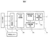
- FIG. 2 shows a configuration diagram of the fusion control unit.
- Fusion control unit 20 includes the following configuration.
- a CAN / Ether receiving unit 201 that receives information from an external sensor and a vehicle sensor that are notified using CAN (Controller Area Network) or Ethernet.
- a Fusion / LDM processing unit 202 that determines where in the vehicle the latest detection target exists based on the received external sensor information and past position information of the same detection target. The vehicle's relative position and the vehicle's relative speed of the integrated detection target are held together with time information of the past few seconds, and the latest movement information of the own vehicle and the own vehicle movement information of the past few seconds are stored together with the time information.
- a position information database 203 to be held.
- a collision time calculation unit 204 that predicts and calculates the time until the host vehicle collides with the detection target based on the position information database.
- a brake control determination processing unit (drive signal output unit) 205 that compares the calculated collision prediction time with a preset brake preload start time and generates and outputs a brake preload drive signal to the electronically controlled brake system.
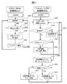
- FIG. 3 shows an example of a processing flow for updating the position information DB based on the external sensor information, among the operations in the fusion control unit of the present embodiment.
- the CAN / Ethernet receiving unit 201 waits for reception of external sensing information notified from the external sensor 10 using CAN or Ethernet (S300).
- the received information is information to be imported into the fusion control unit. If the received information is information that is not required to be incorporated into the fusion control unit, the received information is discarded and reception of the next external sensing information is awaited (S301). .
- the information to be imported into the fusion control unit in S300 is held in the internal buffer so that it is not overwritten by traffic (S302).
- the Fusion / LDM processing unit 202 operates with a time period or an update trigger (S304).
- the update notification separates the marching of the external sensor information and the update of the motion information of the own vehicle (S307).
- the update notification is an update of the movement information of the own vehicle
- the own vehicle information is updated in the position information DB (S308).
- the update notification is an update of external sensor information
- radar detection may become unstable depending on the reflection intensity and distance depending on the size and material of the detection target, so the logic to search for the target has a function to trace the unstable target, and instantaneous detection is also possible. Has a function not to be traced.
- the target when the target can be separated with high accuracy like an image sensor, it may be identified as a new target using the output information of the sensor.
- the position information for target movement prediction may cause the detected position accuracy to be low depending on the detected sensor and separate the target as an object at another position. Therefore, when another sensor detects the target within the detection angle of the sensor with high detection position accuracy, position correction and target combination are performed based on the output result of the sensor with high detection accuracy. Even if it is within the detection angle of a sensor with high detection accuracy, the sensor information with high detection accuracy is not detected, and even when the sensor with low detection accuracy detects it, the target information is detected using the detection information of the sensor with low detection accuracy. Update.
- the targets are integrated and updated as the latest location information DB entry (S311). If the logic of S309 determines that the target is a new target, a position information DB entry is created as a new target (S312).
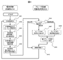
- FIG. 4 shows an example of a processing flow for performing the brake control determination process from the collision time calculation based on the position information DB after the movement information DB is updated, among the operations in the fusion control unit of the present embodiment.
- the collision time calculation unit 204 operates periodically instead of an event trigger (S401). This is because it is better to reduce the dependency between logics and to make loose coupling by being independent from the position information DB creation logic.
- target information being traced is acquired from the position information DB (S402).
- the movement distance is calculated from the past position information and the latest position information acquired from the position information DB, and the relative speed is calculated from the elapsed time (S403).
- the movement amount of the target may be larger than the actual movement amount when multiple sensors with different accuracy are detected, the movement amount when the detection sensor information in the target information is switched uses the past history. It is better to use the average value.
- the movement information of the host vehicle is acquired from the position information DB, and the movement information of the host vehicle such as the host vehicle speed, the steering angle, and the yaw rate is acquired (S404).
- the movement vector of the detection target centered on the own vehicle is generated from the movement information of the own vehicle acquired in S404, and the predicted time from the relative speed and the detected sensor mounting position to the collision is calculated (S405).
- the movement vector may be different because it indicates a past position different from the actual position. Therefore, it is better to treat the movement vector at the time of switching of the detection sensor in the target information as information with low accuracy, and use the position information of the target information having the same detection sensor information.
- the brake control determination processing unit compares the predicted collision time for starting the brake preload set based on the relative speed in advance for each attachment position of the detection sensor from the predicted collision time generated in S405, and determines the necessity of brake preload control. Perform (S406).
- the collision prediction time set in advance when it is known that the position accuracy is low by the sensor detecting the target, the range of the collision prediction time for starting the preload signal of the brake may be broader.
- a brake preload control instruction value for starting the brake preload is generated ( S407).
- the collision prediction time calculated in S405 is compared with the collision prediction time for releasing the preload brake set based on the relative speed in advance for each attachment position of the detection sensor, and is within the range of the brake preload control release, and the brake preload.
- a brake preload control release instruction value for releasing the brake preload is generated (S408).
- the instruction value generated in S407 or S408 is output as a signal to the electronic brake control system (S409).
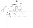
- FIG. 5 shows a brake preload start area when a detection object is detected by the left sensor (second detection unit) 10b without being detected by the front sensor (first detection unit) 10a while the vehicle is turning left.
- a range of the predicted collision time is provided in the direction of predicted traveling of the vehicle from the mounting position of the sensor and the relative speed, and this range is indicated as a brake preload start area.
- SYMBOLS 10 External sensor, 10a ... Front sensor (1st detection part), 10b ... Left sensor (2nd detection part), 20 ... Fusion control unit, 30 ... Electronically controlled brake system, 100 ... Vehicle (own vehicle) , 201... CAN / Ether receiver, 202... Fusion / LDM processor, 203... Position information DB, 204. Collision time calculator, 205.
Landscapes
- Engineering & Computer Science (AREA)
- Mechanical Engineering (AREA)
- Physics & Mathematics (AREA)
- General Physics & Mathematics (AREA)
- Transportation (AREA)
- Regulating Braking Force (AREA)
- Traffic Control Systems (AREA)
Abstract
本発明は、ある検知部では検知対象物を捉えられず、他の検出部で検知対象物を検知した際に備えて、ブレーキの予圧の制御を行う。第1の検知範囲で検知する第1の検知部10aと、第1の検知範囲とは異なる第2の検知範囲で検知する第2の検知部10bと、第1の検知部10aと第2の検知部10bとの検知結果に基づいて、ブレーキ予圧の駆動信号を生成して出力する駆動信号出力部205と、を有し、駆動信号出力部205は、第1の検知部10aで物体が検知されず、且つ第2の検知部10bで物体が検知された場合、ブレーキ予圧の駆動信号を生成して出力する。
Description
この発明は、車載制御装置に関する。
本技術分野の背景技術として、特開2014-104772号公報(特許文献1)がある。特許文献1の要約欄には、「BRK_ECU11は、車載カメラ12で撮影した画像に基づきブレーキ作動対象物を検出し、このブレーキ作動対象物と自車両1との相対速度に基づいて目標ブレーキ予圧作動距離Lprを設定し、自車両1とブレーキ作動対象物との間の実距離Lbrが目標ブレーキ予圧作動距離Lprに達したとき、ブレーキ駆動部17に対して、ディスクブレーキ2のブレーキクリアランスSを微小にするブレーキ予圧Pprを発生させる駆動信号を出力する。」と記載がある。
一方、車両をより高度化するには、人や車、自転車などの飛び出し条件に対応するため、または自動走行を実現するのに必要な自車両周辺の環境を認識するため、単一のセンサーでは不足する検知範囲を、別のセンサーを用いて検知する方式を取ることがある。このように、複数のセンサーを車両へ搭載することで、車両周辺の監視領域を広げることがある。
このとき、複数のセンサーを持つ車両が、フロントへの衝突を検知するカメラでは検知対象物を捉えられず、第2の検出部にて検知対象物を検知する場合が存在し、この時の緊急事態に備えたブレーキの予圧の制御を行うことが必要となる。
そこで本発明は、検知対象物と検知部との関係に応じたブレーキの予圧の制御を行うことを目的とする。
上記課題を解決するため、一例として本発明の車載制御装置は、第1の検知範囲で検知する第1の検知部と、前記第1の検知範囲とは異なる第2の検知範囲で検知する第2の検知部と、前記第1の検知部と前記第2の検知部との検知結果に基づいてブレーキ予圧の駆動信号を生成し、出力する駆動信号出力部と、を有し、前記駆動信号出力部は、前記第1の検出部で物体が検知されず、かつ前記第2の検知部で前記物体が検知された場合、ブレーキ予圧の駆動信号を生成し、出力する。
本発明によれば、検知対象物と検知部との関係に応じたブレーキの予圧の制御を行うことができる。
以下、本発明を実施するための形態について、図面を参照しながら説明する。本実施例は、走行支援システムまたは自動走行システムに係り、例えば、イメージセンサーやミリ波レーダーセンサーなど複数の車載用センサーを車両に搭載し、センサーの出力結果を用い、車両の運転操作の一部、または全部を自動で行う車載制御装置に関する。
図1に示されるように、本実施の形態の車載制御装置は、次の構成を含む。
車両100に搭載される車両の前方向や周辺のセンシングを行う外界センサー10。
自車速度やステアリング操舵角やヨーレートなど自車運動データを出力する車両センサー。
外界センサーと車両センサーの出力結果から検知対象物の情報を統合して、必要に応じてブレーキ予圧信号を生成するフュージョン制御ユニット20。
ブレーキ予圧信号により車両制動を制御する電子制御ブレーキシステム30。
車両100に搭載される車両の前方向や周辺のセンシングを行う外界センサー10。
自車速度やステアリング操舵角やヨーレートなど自車運動データを出力する車両センサー。
外界センサーと車両センサーの出力結果から検知対象物の情報を統合して、必要に応じてブレーキ予圧信号を生成するフュージョン制御ユニット20。
ブレーキ予圧信号により車両制動を制御する電子制御ブレーキシステム30。
図2に、フュージョン制御ユニットの構成図を示す。フュージョン制御ユニット20は、次の構成を含む。
CAN(Controller Area Network)やEthernetを使って通知される外界センサーと車両センサーからの情報を受信するCAN/Ether受信部201。
受信した外界センサー情報及び過去の同一検知対象物の位置情報を元に、最新の検知対象物が自車両のどこの位置に存在するのかを決定するFusion/LDM処理部202。
統合された検知対象物の自車相対位置と自車相対速度を過去数秒間の情報を時刻情報と共に保持し、また、自車両の最新運動情報と過去数秒間の自車両運動情報を時刻情報と共に保持する位置情報データベース203。
位置情報データベースを基に自車両が検知対象物に衝突するまでの時間を予測計算する衝突時間計算部204。
前述の計算した衝突予測時間と予め設定したおいたブレーキ予圧開始時間とを比較し、電子制御ブレーキシステムへブレーキ予圧の駆動信号を生成し出力するブレーキ制御判断処理部(駆動信号出力部)205。
図3に、本実施例のフュージョン制御ユニット内の動作のうち、外界センサー情報を基に位置情報DBを更新する処理フローの例を示す。
まず、CAN/Ether受信部201は、外界センサー10からCANやEthernetを使って通知された外部センシング情報の受信を待つ(S300)。
受信した情報がフュージョン制御ユニットに取り込む対象の情報であるかを判断し、フュージョン制御ユニット内部へ取り込み不要な情報である場合は、受信情報を破棄し次の外部センシング情報の受信を待つ(S301)。
S300でフュージョン制御ユニット内に取り込む対象の情報は、トラフィックにより上書きされないよう内部バッファへ保持する(S302)。
外部センシング情報または自車両の運動情報が更新された旨アップデートをFusion/LDM処理部へ通知する(S303)。
一方、Fusion/LDM処理部202は、時刻周期またはアップデートのトリガーで動作する(S304)。
時刻周期処理で動作したことを判断すると(S305)、位置情報DB内で期限切れになり不要になったターゲット情報の削除、及び期限内で更新のなかったトレース中ターゲット情報の移動予測に伴う位置情報DBリフレッシュを行う(S306)。
S305で周期処理ではないと判断したとき、アップデート通知が外界センサー情報の行進と自車両の運動情報の更新を切り分ける(S307)。
アップデート通知が自車両の運動情報の更新であった場合には位置情報DBのうち自車情報を更新する(S308)。
アップデート通知が外界センサー情報の更新であった場合には、その検知したセンサーの種別、取り付け位置、検知情報を用い、位置情報DBのターゲット情報の中から、センサーの検知時間とターゲット移動予測から同一のターゲットを検索する(S309)。
例えば、レーダーは検知対象の大きさや材質による反射強度や距離によって検知が不安定になるケースもあるため、ターゲットを検索するロジックは、不安定なターゲットをトレースする機能を持ち、また瞬間的な検知はトレース対象とはしない機能を持つ。
また、例えばイメージセンサーのように確度が高くターゲットを分離できる場合には、センサーの出力情報を用いて新規ターゲットであることを識別しても良い。複数の種別のセンサーが同時に同じ物体を捉える時には、ターゲット移動予測の位置情報だけでは、検知したセンサーによっては検知位置精度が低く別の位置にいる物体としターゲットを分離してしまうことがある。そのため、ターゲットが検知位置精度の高いセンサーの検知角内で他のセンサーが検知した場合には、検知精度の高いセンサーの出力結果により位置補正やターゲットの結合を行う。検知精度の高いセンサーの検知角内であっても検知精度の高いセンサーが検知せず、検知精度の低いセンサーが検知する時であっても、検知精度の低いセンサーの検知情報を用いてターゲット情報を更新する。
S309のロジックにより同一ターゲットとして検索できた場合には、ターゲットを統合して最新の位置情報DBエントリとして更新する(S311)。S309のロジックで新規ターゲットと判断した場合には、新規のターゲットとして位置情報DBエントリを作成する(S312)。
図4に、本実施例のフュージョン制御ユニット内の動作のうち、移動情報DBを更新後、位置情報DBを基にした衝突時間計算からブレーキ制御判断処理を行う処理フローの例を示す。
衝突時間計算部204は、イベントトリガーではなく周期的に動作する(S401)。
これは位置情報DB作成ロジックから独立することで、ロジック間の依存度を減らし疎結合とする方が良いためである。
これは位置情報DB作成ロジックから独立することで、ロジック間の依存度を減らし疎結合とする方が良いためである。
衝突予測時間計算周期が始まると、位置情報DBよりトレース中のターゲット情報を取得する(S402)。
位置情報DBから取得した過去の位置情報と最新の位置情報から移動距離を算出し、その経過時間から相対速度を算出する(S403)。
ターゲットの移動量は、精度が異なる複数のセンサーが検知した場合に、実際よりも大きな移動量となる場合があるため、ターゲット情報にある検知センサー情報の切り替わり時の移動量は、過去履歴を使用した平均値を用いる方が良い。また、位置情報DBから自車両の運動情報を取得し、自車速度、ステアリング角度、ヨーレートなどの自車両の運動情報を取得する(S404)。
S404で取得した自車両の運動情報から、自車両を中心とした検知ターゲットの移動ベクトルを生成し、相対速度と検知したセンサーの取り付け位置から衝突までの予測時間を算出する(S405)。検知ターゲットの自車相対移動ベクトルは精度が異なる複数のセンサーが検知した場合に、実際とは異なる過去位置を示してしまい移動ベクトルが異なる場合がある。そのため、ターゲット情報にある検知センサーの切り替わり時の移動ベクトルは確度が低い情報として扱い、検知センサー情報が同一であるターゲット情報の位置情報を用いたほうが良い。
ブレーキ制御判断処理部は、S405で生成した衝突予測時間から検知センサーの取り付け位置毎に予め相対速度を基に設定するブレーキ予圧を開始する衝突予測時間を比較し、ブレーキ予圧制御の必要性判断をおこなう(S406)。予め設定する衝突予測時間については、ターゲットを検知しているセンサーによって位置精度が低いと分かっている場合、そのブレーキの予圧信号を開始する衝突予測時間の範囲をより広域に持っても良い。
S405で計算した衝突予測時間が予め相対速度を基に設定する衝突予測時間の範囲に入っており、かつブレーキ予圧制御中でない場合には、ブレーキ予圧を開始するブレーキ予圧制御指示値を生成する(S407)。
また、S405で計算した衝突予測時間が検知センサーの取り付け位置ごとに予め相対速度を基に設定する予圧ブレーキ解除する衝突予測時間を比較し、ブレーキ予圧制御解除の範囲に入っており、かつブレーキ予圧制御中である場合には、ブレーキ予圧を解除するブレーキ予圧制御時解除指示値を生成する(S408)。
S407またはS408で生成した指示値を電子ブレーキ制御システムへ信号出力する(S409)。
S406でブレーキ予圧の制御が不要と判断した後、または、電子ブレーキ制御システムで信号出力後は、周期処理を終了する(S410)。
図5に、自車が左折中にフロントセンサー(第一の検知部)10aでは検知せず、左側方のセンサー(第二の検知部)10bで検知対象物を検知した時のブレーキ予圧開始エリアの例を示す。この例では左側方のセンサーで検知しているため、そのセンサーの取り付け位置と相対速度から自車進行予測方向に衝突予測時間の範囲が設けられ、その範囲をブレーキ予圧開始エリアと示した。
以上の実施例によれば、検知対象物と検知部との関係に応じたブレーキの予圧の制御を行うことができる。また、複数のセンサーを用い物体を検知する場合であっても、物体を検知したセンサーの取り付け位置、センサーの検知位置精度を考慮に入れたブレーキの予圧制御ができるようになる。
10…外界センサー、10a…フロントセンサー(第一の検知部)、10b…左側方のセンサー(第二の検知部)、20…フュージョン制御ユニット、30…電子制御ブレーキシステム、100…車両(自車両)、201…CAN/Ether受信部、202…Fusion/LDM処理部、203…位置情報DB、204…衝突時間計算部、205…ブレーキ制御判断部(駆動信号出力部)。
Claims (3)
- 第1の検知範囲で検知する第1の検知部と、
前記第1の検知範囲とは異なる第2の検知範囲で検知する第2の検知部と、
前記第1の検知部と前記第2の検知部との検知結果に基づいて、ブレーキ予圧の駆動信号を生成して出力する駆動信号出力部と、を有し、
前記駆動信号出力部は、前記第1の検知部で物体が検知されず、且つ前記第2の検知部で前記物体が検知された場合、前記ブレーキ予圧の駆動信号を生成して出力することを特徴とする車載制御装置。 - 請求項1に記載の車載制御装置において、
前記駆動信号出力部は、前記第1の検知部で物体が検知されず、且つ前記第2の検知部で前記物体が検知され、且つ、前記物体との衝突までの時間が所定の範囲内である場合、前記ブレーキ予圧の駆動信号を生成して出力することを特徴とする車載制御装置。 - 請求項1に記載の車載制御装置において、
第1の検知精度の前記第1の検知部と、前記第1の検知精度より低い第2の検知精度で検知する前記第2の検知部と、で物体を検知する場合、前記第1の検知部の検知結果を基に前記第2の検知部で検知した物体情報を結合し、前記ブレーキ予圧の駆動信号を生成して出力することを特徴とする車載制御装置。
Priority Applications (1)
| Application Number | Priority Date | Filing Date | Title |
|---|---|---|---|
| JP2019505854A JP6779363B2 (ja) | 2017-03-15 | 2018-02-28 | 車載制御装置 |
Applications Claiming Priority (2)
| Application Number | Priority Date | Filing Date | Title |
|---|---|---|---|
| JP2017-049344 | 2017-03-15 | ||
| JP2017049344 | 2017-03-15 |
Publications (1)
| Publication Number | Publication Date |
|---|---|
| WO2018168457A1 true WO2018168457A1 (ja) | 2018-09-20 |
Family
ID=63522159
Family Applications (1)
| Application Number | Title | Priority Date | Filing Date |
|---|---|---|---|
| PCT/JP2018/007431 Ceased WO2018168457A1 (ja) | 2017-03-15 | 2018-02-28 | 車載制御装置 |
Country Status (2)
| Country | Link |
|---|---|
| JP (1) | JP6779363B2 (ja) |
| WO (1) | WO2018168457A1 (ja) |
Citations (2)
| Publication number | Priority date | Publication date | Assignee | Title |
|---|---|---|---|---|
| JP2008143429A (ja) * | 2006-12-12 | 2008-06-26 | Toyota Motor Corp | 衝突予測装置 |
| WO2016038773A1 (ja) * | 2014-09-12 | 2016-03-17 | パナソニックIpマネジメント株式会社 | 衝突防止装置 |
-
2018
- 2018-02-28 JP JP2019505854A patent/JP6779363B2/ja active Active
- 2018-02-28 WO PCT/JP2018/007431 patent/WO2018168457A1/ja not_active Ceased
Patent Citations (2)
| Publication number | Priority date | Publication date | Assignee | Title |
|---|---|---|---|---|
| JP2008143429A (ja) * | 2006-12-12 | 2008-06-26 | Toyota Motor Corp | 衝突予測装置 |
| WO2016038773A1 (ja) * | 2014-09-12 | 2016-03-17 | パナソニックIpマネジメント株式会社 | 衝突防止装置 |
Also Published As
| Publication number | Publication date |
|---|---|
| JP6779363B2 (ja) | 2020-11-04 |
| JPWO2018168457A1 (ja) | 2019-11-07 |
Similar Documents
| Publication | Publication Date | Title |
|---|---|---|
| EP3832621B1 (en) | Convoy travel system | |
| CN110268413B (zh) | 低电平传感器融合 | |
| US10453344B2 (en) | Information processing apparatus and non-transitory recording medium | |
| JP6803657B2 (ja) | 車両制御装置および車両制御システム | |
| US11345279B2 (en) | Device and method for warning a driver of a vehicle | |
| JP6611085B2 (ja) | 車両制御装置 | |
| CN109572690B (zh) | 车辆控制装置 | |
| EP3134888B1 (en) | False warning reduction using location data | |
| CN113264047A (zh) | 车辆控制装置及存储车辆控制用程序的非易失性存储介质 | |
| US10866589B2 (en) | Method for providing an information item regarding a pedestrian in an environment of a vehicle and method for controlling a vehicle | |
| US11613254B2 (en) | Method to monitor control system of autonomous driving vehicle with multiple levels of warning and fail operations | |
| US20160343247A1 (en) | Method and System for Detecting Autonomously Driven Vehicles, for Distance Measurement and for Distance Control | |
| US10870349B2 (en) | Vehicle travel support system | |
| JP7416144B2 (ja) | 運転引継制御装置、方法およびプログラム | |
| KR20190006180A (ko) | 보행자 보호시 자율적인 제동 실패 관리 | |
| US10800432B2 (en) | Rear-side alert system and method of controlling same | |
| US20210009157A1 (en) | Driving assistance apparatus, vehicle, delinquent driving detection system, and server device | |
| JP2018133072A (ja) | 情報処理装置およびプログラム | |
| EP3336824B1 (en) | Vehicle automatic safety function misoperation suppression method | |
| JP6451464B2 (ja) | 衝突回避装置、及び衝突回避システム | |
| CN113165660A (zh) | 驾驶员辅助系统和机动车辅助操作方法 | |
| WO2019009032A1 (ja) | 車両制御装置 | |
| JP6372431B2 (ja) | 衝突予測装置 | |
| KR102616203B1 (ko) | 차량 후측방 경보 제어장치 및 방법 | |
| US10293815B2 (en) | Driver assistance system having controller and controlling method thereof |
Legal Events
| Date | Code | Title | Description |
|---|---|---|---|
| 121 | Ep: the epo has been informed by wipo that ep was designated in this application |
Ref document number: 18767369 Country of ref document: EP Kind code of ref document: A1 |
|
| WWE | Wipo information: entry into national phase |
Ref document number: 2019505854 Country of ref document: JP |
|
| NENP | Non-entry into the national phase |
Ref country code: DE |
|
| 122 | Ep: pct application non-entry in european phase |
Ref document number: 18767369 Country of ref document: EP Kind code of ref document: A1 |