WO2018167972A1 - 画像読取装置、制御方法及び制御プログラム - Google Patents
画像読取装置、制御方法及び制御プログラム Download PDFInfo
- Publication number
- WO2018167972A1 WO2018167972A1 PCT/JP2017/011036 JP2017011036W WO2018167972A1 WO 2018167972 A1 WO2018167972 A1 WO 2018167972A1 JP 2017011036 W JP2017011036 W JP 2017011036W WO 2018167972 A1 WO2018167972 A1 WO 2018167972A1
- Authority
- WO
- WIPO (PCT)
- Prior art keywords
- document
- image
- original
- unit
- image reading
- Prior art date
- Legal status (The legal status is an assumption and is not a legal conclusion. Google has not performed a legal analysis and makes no representation as to the accuracy of the status listed.)
- Ceased
Links
Images





Classifications
-
- G—PHYSICS
- G03—PHOTOGRAPHY; CINEMATOGRAPHY; ANALOGOUS TECHNIQUES USING WAVES OTHER THAN OPTICAL WAVES; ELECTROGRAPHY; HOLOGRAPHY
- G03B—APPARATUS OR ARRANGEMENTS FOR TAKING PHOTOGRAPHS OR FOR PROJECTING OR VIEWING THEM; APPARATUS OR ARRANGEMENTS EMPLOYING ANALOGOUS TECHNIQUES USING WAVES OTHER THAN OPTICAL WAVES; ACCESSORIES THEREFOR
- G03B27/00—Photographic printing apparatus
- G03B27/32—Projection printing apparatus, e.g. enlarger, copying camera
- G03B27/52—Details
- G03B27/62—Holders for the original
-
- H—ELECTRICITY
- H04—ELECTRIC COMMUNICATION TECHNIQUE
- H04N—PICTORIAL COMMUNICATION, e.g. TELEVISION
- H04N1/00—Scanning, transmission or reproduction of documents or the like, e.g. facsimile transmission; Details thereof
-
- H—ELECTRICITY
- H04—ELECTRIC COMMUNICATION TECHNIQUE
- H04N—PICTORIAL COMMUNICATION, e.g. TELEVISION
- H04N1/00—Scanning, transmission or reproduction of documents or the like, e.g. facsimile transmission; Details thereof
- H04N1/387—Composing, repositioning or otherwise geometrically modifying originals
Definitions
- the present disclosure relates to an image reading apparatus, and more particularly, to an image reading apparatus that captures an image of a conveyed document.
- An image reading apparatus such as a scanner that reads an image by conveying a document placed on a document table stops the conveyance of the document when an abnormality such as a jam or skew occurs during the document conveyance, and the document is The image is read again after being re-mounted on the table.
- an abnormality occurs when the majority of a long document having a length of a predetermined size or more is conveyed, if the long document is re-conveyed from the leading edge, a long time is required until the reading process is completed. It will take.
- the long document is a document in which an abnormality is likely to occur during conveyance, if the document is re-conveyed from the leading edge every time an abnormality occurs, an abnormality may occur repeatedly.
- An automatic document reading apparatus that displays image data that is less than one page in the middle of reading when a jam occurs is disclosed.
- This automatic document reading apparatus displays a message for prompting the operator to set a document corresponding to the displayed image and a document corresponding to the subsequent page on the document stacking unit and to instruct resumption of transmission. (See Patent Document 1).
- a scanner that displays a list of stored thumbnail images when the user instructs the start of the scanning process after stopping the scanning process, and the user selects a thumbnail image for which the scanning process is to be resumed. (See Patent Document 2).
- an appropriate instruction for rearranging the document is notified to the user when an abnormality occurs during conveyance of the long document.
- An object of the image reading apparatus, the control method, and the control program is to make it possible to notify a user of an appropriate instruction for rearranging a document when an abnormality occurs during conveyance of a long document. .
- An image reading apparatus includes an imaging unit that captures a document to be conveyed, an abnormality determination unit that determines whether an abnormality has occurred during conveyance of the document, and an abnormality determined to have occurred.
- the control unit for stopping the conveyance of the document the document determination unit for determining whether or not the document is a long document, and the document is determined not to be a long document when the conveyance of the document is stopped. If the document is repositioned and it is determined that the document is a long document, the document is re-aligned so that the first predetermined position in the middle of the document matches the second predetermined position of the image reading apparatus.
- a notification unit for notifying that it is arranged.
- a control method is a control method of an image reading apparatus having an imaging unit that captures an image of a conveyed document, and determines whether an abnormality has occurred during conveyance of the document, When it is determined that an abnormality has occurred, the conveyance of the document is stopped, it is determined whether or not the document is a long document, and when the conveyance of the document is stopped, it is determined that the document is not a long document. If the document is repositioned and it is determined that the document is a long document, the document is re-aligned so that the first predetermined position in the middle of the document matches the second predetermined position of the image reading apparatus. Including notifying of placement.
- a control program is a control program for an image reading apparatus having an imaging unit that captures an image of a conveyed document, and determines whether or not an abnormality has occurred during conveyance of the document.
- the conveyance of the document is stopped, it is determined whether or not the document is a long document, and when the conveyance of the document is stopped, it is determined that the document is not a long document. If the document is repositioned and it is determined that the document is a long document, the document is re-aligned so that the first predetermined position in the middle of the document matches the second predetermined position of the image reading apparatus. The image reading apparatus is notified of the placement.
- the image reading apparatus, the control method, and the control program can notify the user of an appropriate instruction for rearranging a document when an abnormality occurs during conveyance of a long document. It becomes.
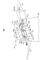
- FIG. 1 is a perspective view showing an image reading apparatus 100.
- FIG. 3 is a diagram for explaining a conveyance path inside the image reading apparatus 100.
- FIG. FIG. 2 is a view of the image reading apparatus 100 as viewed from above.
- 1 is a block diagram illustrating a schematic configuration of an image reading apparatus 100.
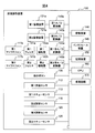
- FIG. 2 is a diagram illustrating a schematic configuration of a storage device 150 and a CPU 160.
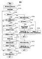
- FIG. 5 is a flowchart illustrating an example of an operation of document reading processing. It is a figure which shows an example of a elongate original document. 5 is a diagram illustrating an example of a read image 700.
- FIG. It is a figure which shows an example of the screen displayed on an information processing apparatus or a display apparatus.
- FIG. 6 is a diagram illustrating an example of a state in which a long document is rearranged. It is a figure which shows an example of the 2nd image.
- 5 is a diagram illustrating an example of a composite image 1010.
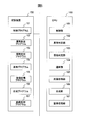
- FIG. 10 is a diagram showing a schematic configuration of another processing circuit 270.
- FIG. 1 is a perspective view showing an image reading apparatus 100 configured as an image scanner.
- the image reading apparatus 100 includes an upper casing 101, a lower casing 102, a document table 103, a discharge table 105, a plurality of operation buttons 106, a display device 107, and the like.
- the upper casing 101 is disposed at a position covering the upper surface of the image reading apparatus 100, and is engaged with the lower casing 102 by a hinge so as to be opened and closed when the document is blocked, for example, when cleaning the inside of the image reading apparatus 100. Yes.
- the document table 103 is engaged with the lower housing 102 so that a document can be placed thereon.
- the document table 103 is provided with side guides 104a and 104b that are movable in a direction perpendicular to the document conveyance direction.
- the side guides 104a and 104b may be collectively referred to as a side guide 104.
- the discharge table 105 is engaged with the lower housing 102 so as to hold the discharged document.
- the operation button 106 is disposed on the side of the lower housing 102, and when pressed, generates and outputs an operation detection signal corresponding to each button.
- the display device 107 includes a display composed of liquid crystal, organic EL (Electro-Luminescence), and the like, and an interface circuit that outputs image data to the display, and displays the image data on the display.
- a display composed of liquid crystal, organic EL (Electro-Luminescence), and the like
- an interface circuit that outputs image data to the display, and displays the image data on the display.
- FIG. 2 is a diagram for explaining a conveyance path inside the image reading apparatus 100.
- the conveyance path in the image reading apparatus 100 includes a chute roller 110, pick rollers 111a and 111b, a contact sensor 112, first light emitters 113a and 113b, first light receiver 113c and d, paper feed rollers 114a and 114b, and a retard roller 115a.
- B second light emitter 116a, second light receiver 116b, first microphone 117a, second microphone 117b, first transport rollers 118a, b, first driven rollers 119a, b, third light emitter 120a, third light receiver.
- first imaging device 121a second imaging device 121b, first illumination device 122a, second illumination device 122b, second transport rollers 123a, 123b, second driven rollers 124a, 124b, fourth light emitters 125a, b And fourth light receivers 125c and 125d.
- the pick rollers 111a and 111b may be collectively referred to as the pick roller 111.
- the paper feed rollers 114a and 114b may be collectively referred to as the paper feed roller 114.
- the retard rollers 115a and 115b may be collectively referred to as a retard roller 115.
- the first transport rollers 118a and 118b may be collectively referred to as the first transport roller 118.
- the first driven rollers 119a and 119b may be collectively referred to as a first driven roller 119.
- the second transport rollers 123a and 123b may be collectively referred to as the second transport roller 123.
- the second driven rollers 124a and 124b may be collectively referred to as a second driven roller 124.
- the lower surface of the upper casing 101 forms an upper guide 101a of the document conveyance path
- the upper surface of the lower casing 102 forms a lower guide 102a of the document conveyance path.
- an arrow A1 indicates the document conveyance direction.
- upstream means upstream in the document transport direction A1
- downstream means downstream in the document transport direction A1.
- the chute roller 110 is provided on the document table 103 and comes into contact with the document located on the lowermost side of the documents placed on the document table 103, and sends the document in the document conveyance direction A1.
- the pick roller 111 is provided in the lower housing 102 on the downstream side of the chute roller 110, and comes into contact with the document located at the lowermost side among the plurality of documents placed on the document table 103. Is sent in the document transport direction A1. Due to the action of the chute roller 110 and the pick roller 111, the image reading apparatus 100 conveys the document by a so-called bottom take-out method.
- the contact sensor 112 is arranged on the downstream side of the pick roller 111 and on the upstream side of the paper feed roller 114 and the retard roller 115, and detects whether or not a document is placed on the document table 103.
- the contact sensor 112 generates and outputs a first document detection signal whose signal value changes depending on whether the document is placed on the document table 103 or not.
- the contact sensor 112 may be referred to as a first document sensor 112.
- the first light emitters 113a and 113b and the first light receivers 113c and d are opposed to the downstream side of the pick roller 111 and the upstream side of the paper feed roller 114 and the retard roller 115, respectively, with the conveyance path of the document interposed therebetween. Be placed.
- the first light emitters 113a and 113b emit light toward the first light receivers 113c and 113d, respectively.
- the first light receivers 113c and 113d detect the light emitted from the first light emitters 113a and 113b, respectively, and generate and output a first skew detection signal that is an electrical signal corresponding to the detected light.
- the first skew detection signal is a signal whose signal value changes depending on whether or not a document exists between the first light emitters 113a and 113b and the first light receivers 113c and 113d.
- the first light emitters 113a and 113b and the first light receivers 113c and d may be collectively referred to as a first skew sensor 113.
- the paper feed roller 114 is provided in the lower casing 102 and sends out the document placed on the document table 103 in the document conveyance direction A1.
- the retard roller 115 is provided in the upper housing 101 at a position facing the paper feed roller 114, and performs a document separation operation.
- the second light emitter 116a and the second light receiver 116b are opposed to the downstream side of the paper feed roller 114 and the retard roller 115 and the upstream side of the first conveyance roller 118 and the first driven roller 119 with the original conveyance path interposed therebetween.
- the second light emitter 116a emits light toward the second light receiver 116b.
- the second light receiver 116b detects the light emitted from the second light emitter 116a, and generates and outputs a second document detection signal that is an electrical signal corresponding to the detected light. That is, the second document detection signal is a signal whose signal value changes depending on whether or not a document exists between the second light emitter 116a and the second light receiver 116b.
- the second light emitter 116a and the second light receiver 116b may be collectively referred to as a second document sensor 116.
- the first microphone 117a and the second microphone 117b collect sounds generated while the document is being conveyed, and output analog signals generated from the collected sounds.
- the first microphone 117a and the second microphone 117b are arranged inside the upper housing 101 (not shown) on the downstream side of the paper feed roller 114 and the retard roller 115 and on the upstream side of the first transport roller 118 and the first driven roller 119. ) Is fixed and arranged.
- the first microphone 117a and the second microphone 117b may be collectively referred to as a microphone 117.
- the first transport roller 118 is provided in the upper housing 101 on the downstream side of the retard roller 115 and the upstream side of the first imaging device 121a in the document transport direction A1.
- the first driven roller 119 is provided on the lower housing 102 at a position facing the first transport roller 118.
- the third light emitter 120a and the third light receiver 120b are disposed on the downstream side of the first conveying roller 118 and the first driven roller 119 and on the upstream side of the imaging positions of the first imaging device 121a and the second imaging device 121b. It arrange
- the third light emitter 120a emits light toward the third light receiver 120b.
- the third light receiver 120b detects the light emitted from the third light emitter 120a, generates and outputs a third document detection signal that is an electrical signal corresponding to the detected light. That is, the third document detection signal is a signal whose signal value changes depending on whether or not a document exists between the third light emitter 120a and the third light receiver 120b.
- the third light emitter 120a and the third light receiver 120b may be collectively referred to as a third document sensor 120.
- the first imaging device 121a has a reduction optical system type imaging sensor including an imaging element composed of a CCD (Charge Coupled Device) arranged in the main scanning direction. This imaging sensor images the back side of the conveyed document and generates and outputs an analog image signal.
- the second imaging device 121b has a reduction optical system type imaging sensor including an imaging element composed of a CCD arrayed in the main scanning direction. This imaging sensor images the surface of the conveyed document and generates and outputs an analog image signal. Note that only one of the first imaging device 121a and the second imaging device 121b may be arranged to read only one side of the document.
- a CIS Contact Image Sensor
- CMOS Complementary Metal Metal Oxide Semiconductor
- the first imaging device 121a and the second imaging device 121b may be collectively referred to as the imaging device 121.
- the imaging device 121 is an example of an imaging unit.
- the first illumination device 122a has a light source that illuminates the back surface of the document and a backing used for the surface of the document, and is between the first imaging device 121a and the document conveyance path and the second imaging device 121b. It is provided at an opposing position.
- the second illumination device 122b has a light source that illuminates the surface of the document and a backing used for the back surface of the document, is between the second imaging device 121b and the document transport path, and is in the first imaging. It is provided at a position facing the device 121a.
- the first lighting device 122a and the second lighting device 122b may be collectively referred to as the lighting device 122.
- the second transport roller 123 is provided in the upper housing 101 on the downstream side of the first imaging device 121a and the retard roller 115 in the document transport direction A1.
- the second driven roller 124 is provided in the lower housing 102 at a position facing the second transport roller 123.
- the fourth light emitters 125a and 125b and the fourth light receivers 125c and 125d are arranged on the downstream side of the second conveying roller 123 and the second driven roller 124 so as to face each other across the original conveying path.
- the fourth light emitters 125a and 125b emit light toward the fourth light receivers 125c and 125d, respectively.
- the fourth light receivers 125c and 125d detect the light emitted from the fourth light emitters 125a and 125b, respectively, and generate and output a second skew detection signal that is an electrical signal corresponding to the detected light.
- the second skew detection signal is a signal whose signal value changes depending on whether or not a document exists between the fourth light emitters 125a and 125b and the fourth light receivers 125c and 125d.
- the fourth light emitters 125 a and 125 b and the fourth light receivers 125 c and d may be collectively referred to as a second skew sensor 125.
- the document placed on the document table 103 is arranged such that the chute roller 110, the pick roller 111, and the paper feed roller 114 rotate in the directions of arrows A2, A3, and A4 in FIG. Are conveyed in the document conveying direction A1.
- the retard roller 115 rotates in the direction of the arrow A5
- the retard roller 115 contacts the paper feed roller 114 among the documents placed on the document table 103. Only the original is separated.
- the document is fed between the first conveying roller 118 and the first driven roller 119 while being guided by the upper guide 101a and the lower guide 102a.
- the original is fed between the first illumination device 122a and the second illumination device 122b (that is, between the first imaging device 121a and the second imaging device 121b) by the first conveying roller 118 rotating in the direction of the arrow A6.
- the document read by the imaging device 121 is discharged onto the discharge table 105 when the second transport roller 123 rotates in the direction of the arrow A7.
- FIG. 3 is a view of the image reading apparatus 100 as viewed from above with the upper housing 101 removed.
- the first light receivers 113c and d are arranged outside the side guide 104 in a direction (main scanning direction) orthogonal to the document transport direction A1.
- the fourth light receivers 125c, d are disposed outside the side guide 104 in the direction orthogonal to the document transport direction A1.
- the first skew sensor 113 may be disposed upstream of the pick roller 111 or downstream of the paper feed roller 114 and the retard roller 115 in the document transport direction A1 (sub-scanning direction).
- the second skew sensor 125 may be disposed upstream of the second transport roller 123 and the second driven roller 124 in the document transport direction A1.
- a position 126a illustrated in FIG. 3 indicates a position on the lower casing 102 that the first microphone 117a faces in a state in which the upper casing 101 is closed, and a position 126b is a second position in the state in which the upper casing 101 is closed.
- casing 102 which the microphone 117b opposes is shown.
- the first microphone 117a is provided at one end (a predetermined distance from the side wall 127a of the document conveyance path) in the direction orthogonal to the document conveyance direction A1.
- the second microphone 117b is provided on the other end side (a predetermined distance from the side wall 127b of the document conveyance path) in the direction orthogonal to the document conveyance direction A1.
- markers 128a and 128b are arranged on the downstream side of the first conveyance roller 118 and the first driven roller 119 and on the upstream side of the imaging position by the imaging device 121.
- the markers 128a and 128b are arranged outside the side guide 104 in a direction orthogonal to the document conveyance direction A1.
- the markers 128a and 128b may be arranged on the upstream side of the first conveying roller 118 and the first driven roller 119 or on the downstream side of the imaging position by the imaging device 121 in the document conveying direction A1.
- the markers 128a and 128b may be disposed on the inner side of the side guide 104 in the direction orthogonal to the document conveyance direction A1.
- the arrangement position of the markers 128a and b is an example of a second predetermined position.
- Markers 128a and 128b are silk-printed on the lower guide 102a. Note that the markers 128a and 128b may be any type, and may be a seal or the like affixed on the lower guide 102a.
- FIG. 4 is a block diagram illustrating a schematic configuration of the image reading apparatus 100.
- the image reading apparatus 100 includes a first A / D converter 140a, a second A / D converter 140b, a first filter 141a, a second filter 141b, a first amplifier 142a, a second amplifier 142b, It further includes a single sound A / D converter 143a, a second sound A / D converter 143b, a drive device 144, an interface device 145, a storage device 150, a CPU (Central Processing Unit) 160, a control circuit 170, and the like.
- a first A / D converter 140a a second A / D converter 140b
- a first filter 141a a second filter 141b
- a first amplifier 142a a second amplifier 142b
- the first A / D converter 140a performs analog-to-digital conversion on the analog image signal output from the first imaging device 121a to generate digital image data, and outputs the digital image data to the CPU 160.
- the second A / D converter 140b converts the analog image signal output from the second imaging device 121b from analog to digital to generate digital image data, and outputs the digital image data to the CPU 160. These digital image data are used as a read image.
- the first A / D converter 140a and the second A / D converter 140b may be collectively referred to as an A / D converter 140.
- the first filter 141a applies a bandpass filter that passes a signal in a predetermined frequency band to the analog signal output from the first microphone 117a, and outputs the signal to the first amplifier 142a.
- the first amplifier 142a amplifies the signal output from the first filter 141a and outputs the amplified signal to the first sound A / D converter 143a.
- the first sound A / D converter 143a converts the analog signal output from the first amplifier 142a into a digital signal and outputs the digital signal to the CPU 160.
- the signal output from the first sound A / D converter 143a is referred to as a first sound signal.
- the second filter 141b applies a band pass filter that passes a signal in a predetermined frequency band to the analog signal output from the second microphone 117b, and outputs the signal to the second amplifier 142b.
- the second amplifier 142b amplifies the signal output from the second filter 141b and outputs the amplified signal to the second sound A / D converter 143b.
- the second sound A / D converter 143b converts the analog signal output from the second amplifier 142b into a digital signal and outputs the digital signal to the CPU 160.
- the signal output from the second sound A / D converter 143b is referred to as a second sound signal.
- the first filter 141a and the second filter 141b may be collectively referred to as a filter 141.
- the first amplifier 142a and the second amplifier 142b may be collectively referred to as an amplifier 142.
- the first sound A / D converter 143a and the second sound A / D converter 143b may be collectively referred to as a sound A / D converter 143.
- the driving device 144 includes one or a plurality of motors, and rotates the chute roller 110, the pick roller 111, the paper feeding roller 114, the retard roller 115, the first conveying roller 118, and the second conveying roller according to a control signal from the CPU 160. Then, the document transport operation and separation operation are performed.
- the interface device 145 has an interface circuit conforming to a serial bus such as a USB, for example, and is electrically connected to an information processing device (not shown) (for example, a personal computer, a portable information terminal, etc.) to display a read image and various information. Send and receive.
- an information processing device for example, a personal computer, a portable information terminal, etc.
- a communication unit including an antenna that transmits and receives wireless signals and a wireless communication interface circuit that transmits and receives signals through a wireless communication line according to a predetermined communication protocol may be used.
- the predetermined communication protocol is, for example, a wireless LAN (Local Area Network).
- the storage device 150 includes a memory device such as a RAM (Random Access Memory) and a ROM (Read Only Memory), a fixed disk device such as a hard disk, or a portable storage device such as a flexible disk and an optical disk.
- the storage device 150 also stores computer programs, databases, tables, and the like used for various processes of the image reading apparatus 100.
- the computer program may be installed in the storage device 150 from a computer-readable portable recording medium using a known setup program or the like.
- the portable recording medium is, for example, a CD-ROM (compact disk read only memory) or a DVD-ROM (digital versatile disk read only memory). Further, the storage device 150 stores the read image.
- the CPU 160 operates based on a program stored in storage device 150 in advance.
- the CPU 160 may be a general purpose processor. Instead of the CPU 160, a DSP (digital signal processor), an LSI (large scale integration), or the like may be used. Instead of the CPU 160, an ASIC (Application Specific Integrated Circuit), an FPGA (Field-Programmable Gate Array), or the like may be used.
- DSP digital signal processor
- LSI large scale integration
- ASIC Application Specific Integrated Circuit
- FPGA Field-Programmable Gate Array
- the CPU 160 includes an operation button 106, a first document sensor 112, a first skew sensor 113, a second document sensor 116, a third document sensor 120, a second skew sensor 125, an imaging device 121, an A / D converter 140, and a microphone 117. , A filter 141, an amplifier 142, a sound A / D converter 143, a drive device 144, an interface device 145, a storage device 150, a processing circuit 170, and the like, and controls these components. The CPU 160 performs drive control of the drive device 144, document reading control of the imaging device 121, and the like, and acquires a read image.
- the processing circuit 170 performs predetermined image processing such as shading correction and inclination correction on the read image acquired from the imaging device 121.
- the processing circuit 170 stores the read image subjected to the image processing in the storage device 150.
- an LSI, DSP, ASIC, FPGA, or the like may be used as the processing circuit 170.
- FIG. 5 is a diagram showing a schematic configuration of the storage device 150 and the CPU 160.
- the storage device 150 stores a control program 151, an abnormality determination program 152, a document determination program 153, a notification program 154, an image acquisition program 155, a composition program 156, and an image processing program 157. Is done.
- Each of these programs is a functional module implemented by software operating on the processor.
- the CPU 160 reads each program stored in the storage device 150 and operates according to each read program, whereby the control unit 161, the abnormality determination unit 162, the document determination unit 163, the notification unit 164, the image acquisition unit 165, and the synthesis unit. 166 and the image processing unit 167 function.
- FIG. 6 is a flowchart showing an example of the operation of document reading processing.
- the operation flow described below is mainly executed by the CPU 160 in cooperation with each element of the image reading apparatus 100 based on a program stored in the storage device 150 in advance.
- control unit 161 waits until the operation button 106 for instructing reading of a document is pressed by the user and an operation detection signal for instructing reading of the document is received from the operation button 106 (step S101). ).
- the controller 161 drives the driving device 144 to rotate the chute roller 110, the pick roller 111, the paper feed roller 114, the retard roller 115, the first conveyance roller 118, and the second conveyance roller to convey the document.
- the image acquisition unit 165 causes the imaging apparatus 121 to read the conveyed document and acquires a read image via the A / D converter 140.
- the abnormality determination unit 162 determines whether or not an abnormality has occurred during document conveyance (step S103).
- the abnormality determination unit 162 determines whether or not document skew or jam has occurred as an abnormality during document conveyance.
- the abnormality determination unit 162 determines whether document skew or jam has occurred based on the first skew detection signal received from the first skew sensor 113 or the second skew detection signal received from the second skew sensor 125. To do. When the first skew detection signal indicates that the document is present at the position of the first skew sensor 113, the abnormality determination unit 162 determines that the document is being conveyed at an angle and that the document is skewed or jammed. Similarly, when the second skew detection signal indicates that the document exists at the position of the second skew sensor 125, the abnormality determination unit 162 is transported with the document skewed, and document skew or jam has occurred. Is determined.
- the abnormality determination unit 162 generates a jam of the document based on the first sound signal received from the first sound A / D converter 143a or the second sound signal received from the second sound A / D converter 143b. Determine whether or not.
- the abnormality determination unit 162 determines that a louder sound is generated due to document distortion or the like, and a document jam has occurred.
- the abnormality determination unit 162 generates a loud sound due to document distortion or the like, and the original jam occurs. It is determined that The predetermined value and the predetermined time are determined in advance by an experiment.
- control unit 161 stops the driving device 144 and stops the document conveyance (step S104).
- the document determination unit 163 determines whether or not the document being conveyed is a long document (step S105).
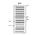
- FIG. 7A shows an example of a long document.
- the long original D is an original having a predetermined size, for example, a double letter size (432 ⁇ 279 mm) or more.
- a document having a length of 1 meter or more and showing a seismometer measurement result or an electrocardiogram may be used.
- Document determination unit 163 determines whether the document is a long document based on the second document detection signal received from second document sensor 116 or the third document detection signal received from third document sensor 120. . When the control unit 161 conveys the document, the document determination unit 163 continues the document when the second document detection signal indicates that the document exists at the position of the second document sensor 116 for a predetermined time or longer. Is a long document. Similarly, the document determination unit 163 indicates that the document is present at the position of the third document sensor 120 by the third document detection signal continuously for a predetermined time or more while the control unit 161 is transporting the document. In this case, it is determined that the document is a long document. The predetermined time is set to a value obtained by dividing the length of the shortest original document by the document conveyance speed.
- the notification unit 164 When it is determined that the document is not a long document when the conveyance of the document is stopped, the notification unit 164 notifies the user that the document is to be rearranged (step S106), and the series of steps is completed.
- the notification unit 164 notifies the information processing device (not shown) by transmitting information via the interface device 145. Alternatively, the notification unit 164 may be notified by displaying information on the display device 107. When it is determined that the document is not a long document, the notification unit 164 notifies that the entire document is placed on the document table 103 so that the document is re-conveyed from the top. Note that the notification unit 164 only needs to notify that the original is to be rearranged when it is determined that the original is not a long original, and may not notify how the original is to be rearranged.
- the notification unit 164 deletes the read image acquired by the image acquisition unit 165 so far without saving it in the storage device 150.
- the notification unit 164 determines a rearrangement position where the document is to be rearranged (step S107).
- the notification unit 164 determines the rearrangement position based on the read image acquired by the image acquisition unit 165 until an abnormality occurs during conveyance of the document.
- the notification unit 164 determines, as the rearrangement position, a position in the middle of the original that should be aligned with the arrangement positions of the markers 128a and 128b in the original conveyance direction A1.
- the rearrangement position is an example of a first predetermined position.
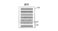
- FIG. 7B is a diagram illustrating an example of a read image 700 that is captured until the conveyance of the document stops when an abnormality occurs during the conveyance of the long document D illustrated in FIG. 7A.
- FIG. 7B when the position P1 in the middle of the long original D in FIG. 7A passes the paper feed roller 114 and the retard roller 115, a jam of the original occurs, and the read image 700 is read from the top of the long original D.
- An example is shown in which an image obtained up to position P2 is acquired.
- the composition unit 166 synthesizes the read image captured until the document conveyance stops and the read image captured after the document conveyance is resumed.
- the read image captured until the document conveyance is stopped may be referred to as a first image
- the read image captured after the document conveyance is resumed may be referred to as a second image.
- the synthesizing unit 166 In order for the synthesizing unit 166 to correctly synthesize the first image and the second image, it is necessary to correctly specify the position to be synthesized. For this reason, the first image and the second image include overlapping portions. Is preferred.
- the notification unit 164 positions the region M ′ of the long document D corresponding to the region M1 that is a predetermined distance from the rear end of the first image in the document transport direction A1 on the upstream side from the imaging position by the imaging device 121.
- the rearrangement position of the document is determined.
- the region M ′ of the long document D is also captured in the second image, and the combining unit 166 combines the first image and the second image based on the overlapping portion included in the first image and the second image. can do.
- the overlapping portion includes characters, designs, and the like printed on the long document D so that the combining unit 166 can accurately detect the overlapping portion in the first image and the second image. Therefore, the notification unit 164 extracts edge pixels from the first image.
- the notification unit 164 is a difference between luminance values or color values (R value, G value, or B value) of pixels adjacent to each other in the horizontal and vertical directions in the first image or a plurality of pixels that are separated from the pixels by a predetermined distance. If the absolute value of exceeds the threshold, the pixel is extracted as an edge pixel.
- the notification unit 164 indicates that the luminance value or color value of each pixel in the first image is less than the threshold value, and the luminance value or color value of a pixel adjacent to the pixel or a pixel separated from the pixel by a predetermined distance is the threshold value. If so, the pixel may be extracted as an edge pixel.
- the notification unit 164 considers that the region from which the edge pixel is extracted in the first image includes a character, a design, and the like, and determines a region to be an overlapping portion so that the region from which the edge pixel is extracted is included. Thereby, the synthetic
- the synthesis unit 166 sets the overlapping portion so that the region where the edge pixels are extracted is included in the first image on either side. Determine the area to be. Also in that case, the composition unit 166 can accurately detect an overlapping portion of the second image with the first image.
- the notification unit 164 regards an area in which no edge pixel is extracted in the first image as a background area in which a background is reflected without including characters, symbols, and the like. Then, the notification unit 164 sets the position in the region B ′ of the long document D corresponding to the background region B1 across the direction (main scanning direction) orthogonal to the document transport direction A1 of the first image as the rearrangement position.
- the synthesizing unit 166 can connect the first image and the second image in the background area included in the first image and the second image, and in the image obtained by synthesizing the first image and the second image, characters, designs, etc. Can be prevented from becoming discontinuous.
- the composition unit 166 repositions the position of the long document D corresponding to the position where the background region exists in the first image on both surfaces. Set to.
- the composition unit 166 sets the position of the long document D corresponding to the background area located on the most rear end (lower end) side as the rearrangement position. To do. As a result, the composition unit 166 can minimize the amount of the re-conveyed long document.
- the combining unit 166 re-positions the long document D corresponding to the background region having the largest width in the document transport direction A1 (sub-scanning direction). You may set to an arrangement position. Thereby, the synthetic
- the image processing unit 167 performs image processing such as encoding (image compression) on the read image for each predetermined unit such as A4 size or A3 size. Therefore, the notification unit 164 may set the position of the long document D corresponding to the boundary of a predetermined unit on which image processing is executed as the rearrangement position. Thereby, the composition unit 166 can connect the first image and the second image at the boundary of the predetermined unit in which the image processing is executed, and the image for each predetermined unit in which the image processing is executed by the image processing unit 167 is The image is formed by one read image without extending over a plurality of read images. Therefore, it is possible to prevent the image for each predetermined unit on which the image processing is performed from including a discontinuous region due to the connected portion of the two read images.
- image processing unit 167 performs image processing such as encoding (image compression) on the read image for each predetermined unit such as A4 size or A3 size. Therefore, the notification unit 164 may set the position of the long document D corresponding to the boundary of
- the notification unit 164 notifies the user that the original is to be rearranged so that the determined rearrangement position matches the arrangement position of the markers 128a and 128b (step S108), and the series of steps ends.
- the notification unit 164 notifies the information processing apparatus (not shown) by transmitting information via the interface apparatus 145.
- the notification unit 164 may be notified by displaying information on the display device 107.
- the notification unit 164 rearranges the original so that the rearrangement position matches the arrangement position of the markers 128a and 128b when it is determined that the original is a long original when the conveyance of the original is stopped. Notify you.
- the notification unit 164 notifies that the document is to be rearranged, and the first image captured until the conveyance of the document is stopped is displayed on the information processing device or the display device 107 via the interface device 145. Output.
- FIG. 8 is a diagram illustrating an example of a screen 800 displayed on the information processing apparatus or the display apparatus 107.
- the first image 801, the display 802 of the position in the first image 801 corresponding to the rearrangement position, and the rearrangement position are matched with the arrangement position of the markers 128a and 128b.
- a notification 803 prompting the user to rearrange the document is displayed.
- the screen 800 allows the user to recognize how to rearrange the manuscript and improve the convenience for the user.
- the user rearranges the long document on the image reading apparatus 100 with reference to the screen 800 displayed on the information processing apparatus or the display device 107. In the example shown in FIG.
- the character “E” in the first image 801 is such that an area including the characters “F” and “G” in the first image 801 is an overlapping portion of the first image 801 and the second image.
- ”And“ F ” are set as rearrangement positions.
- FIG. 9 is a diagram illustrating an example of a state in which the long document D is rearranged on the image reading apparatus 100.
- FIG. 9 is a view of the image reading apparatus 100 as viewed from above with the upper housing 101 removed.
- the rearrangement position corresponding to the background area between “E” and “F” set by the notification unit 164 matches the arrangement position of the markers 128a and 128b. Have been rearranged by the user. Thereafter, when the user presses the operation button 106 for instructing reading of the document, the document reading process is re-executed. In the re-executed document reading process, the imaging device 121 captures the second image so that the characters “A” to “D” in the long document D are not included and the characters “F” and “G” are included. Is done.
- the notification unit 164 stores the read image acquired by the image acquisition unit 165 so far as the first image in the storage device 150 and stores it.
- the image acquisition unit 165 determines whether or not a predetermined unit of read image has been acquired from the imaging device 121 (step S109).
- the abnormality determination unit 162 returns the process to step S103 and determines again whether or not an abnormality has occurred during the conveyance of the document.
- the composition unit 166 determines whether or not the first image saved in the original reading process executed before the current original reading process is stored in the storage device 150. Is determined (step S110).
- the compositing unit 166 proceeds to step S116.
- the combining unit 166 includes the first image stored in the storage device 150, the second image newly captured after resuming the conveyance of the document, Are detected (step S111).
- the synthesizing unit 166 detects an overlapping portion of the first image and the second image using, for example, a known pattern matching technique.
- the synthesizing unit 166 extracts, in the second image, an area having the same size as the predetermined area that is set to be an overlapping portion in the first image while shifting the position thereof, and the predetermined area;
- the degree of similarity with each extracted region is calculated.
- As the degree of similarity for example, a normalized cross-correlation value is used.
- the synthesis unit 166 detects the extracted region as an overlapping portion.
- the compositing unit 166 determines whether or not an overlapping portion between the first image and the second image has been detected (step S112).
- the control unit 161 stops the driving device 144 and stops the conveyance of the document (step S113).
- the notification unit 164 determines the rearrangement position where the original is to be rearranged based on the first image stored in the storage device 150 in the same manner as the process of step S107.
- the notification unit 164 notifies the rearrangement of the document so that the determined rearrangement position matches the arrangement position of the markers 128a and 128b in the same manner as the process of step S108 (step S114), and ends the series of steps. To do.
- the control unit 161 stops the document conveyance, and the notification unit 164 Re-notify the user to place it in an appropriate location.
- the image reading apparatus 100 prompts the user to rearrange the original at the correct position when the user rearranges the original at the wrong position, and promptly executes the restoration process. It becomes possible.
- the combining unit 166 combines the first image and the second image, and generates a combined image obtained by combining the first image and the second image. Generate (step S115).
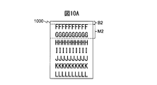
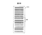
- FIG. 10A is a diagram illustrating an example of the second image 1000 captured after resuming the conveyance of the rearranged document as illustrated in FIG. 9, and FIG. 10B is a diagram illustrating the first image 700 illustrated in FIG. 7B. It is a figure which shows an example of the synthesized image 1010 which synthesize
- the region M2 is an overlapping portion with the first image detected by the combining unit 166
- the region B2 is a region corresponding to the background region B1 of the first image.
- the synthesizing unit 166 synthesizes the first image 700 and the second image 1000 so that the area M1 of the first image 700 and the area M2 of the second image 1000 are merged to generate a synthesized image 1010.
- the combining unit 166 is positioned above a predetermined position (for example, the lower end) of the background area B1 of the first image 700 and below a predetermined position (for example, the lower end) of the background area B2 of the second image 1000.
- the composite image 1010 is generated by combining the regions to be processed.
- the method of combining the first image 700 and the second image 1000 is not limited to the above, and the combining unit 166 may generate the combined image by combining the first image 700 and the second image 1000. Good.
- the image processing unit 167 performs image processing such as encoding (image compression) for each predetermined unit such as A4 size or A3 size on the read image or the synthesized image (step S116).
- the image processing unit 167 transmits the processed data subjected to the image processing to the information processing apparatus (not illustrated) via the interface apparatus 145 (step S117). Note that, when not connected to the information processing apparatus, the image processing unit 167 stores the processing data in the storage device 150.
- control unit 161 is configured to use the second document sensor 116 or the third document sensor 120. It is determined whether or not a document remains at the position (step S118).
- control unit 161 If the document remains at the position of the second document sensor 116 or the third document sensor 120, the control unit 161 returns the process to step S103 and repeats the processes of steps S103 to S118.
- control unit 161 stops the driving device 144 to stop the document conveyance (step S113), and a series of processes. Exit.
- step S105 the process of determining whether or not the document is a long document shown in step S105 may be executed at other timing such as between steps S102 and S103.
- step S116 may be omitted.
- step S117 the image processing unit 167 transmits the read image or the composite image to the information processing apparatus. Further, the processing of steps S112 to S114 may be omitted.
- the image reading apparatus 100 may accept a reread instruction from the top of the document by the user when an abnormality occurs during conveyance of the long document.
- the control unit 161 deletes the first image stored in the storage device 150. Thereby, the first image and the second image are not combined, and the user can acquire the read image reread from the top. The user can select whether to acquire the read image that is read continuously or to acquire the read image that is read in multiple times, which can improve the convenience of the user It becomes.
- the image reading apparatus 100 determines a rearrangement position in the middle of the original when an abnormality occurs during conveyance of the long original, and determines the determined rearrangement position as the arrangement position of the markers 128a and 128b. The user is notified that the original is to be rearranged so as to match. As a result, the image reading apparatus 100 can notify the user of an appropriate instruction for rearranging the original when an abnormality occurs during conveyance of the long original. Further, the image reading apparatus 100 can execute re-conveying and re-reading of a document from the middle of the document, and can reduce the total processing time of the document reading process for a long document. Further, since the user can move the long original by a predetermined distance from the position where the long original has stopped without completely removing the abnormal long original from the image reading apparatus 100, the user can rearrange the original. It became possible to improve the performance.
- FIG. 11 is a block diagram showing a schematic configuration of a processing circuit 270 in an image reading apparatus according to another embodiment.
- the processing circuit 270 is used in place of the processing circuit 170 of the image reading apparatus 100, and executes document reading processing instead of the CPU 160.
- the processing circuit 270 includes a control circuit 271, an abnormality determination circuit 272, a document determination circuit 273, a notification circuit 274, an image acquisition circuit 275, a composition circuit 276, an image processing circuit 277, and the like.
- the control circuit 271 is an example of a control unit and has the same function as the control unit 161.
- the control circuit 271 outputs a control signal to the driving device 144 to drive and stop the driving device 144.
- the abnormality determination circuit 272 is an example of an abnormality determination unit and has the same function as the abnormality determination unit 162.
- the abnormality determination circuit 272 receives the first skew detection signal, the second skew detection signal, or the sound signal from the first skew sensor 113, the second skew sensor 125, or the microphone 117.
- the abnormality determination circuit 272 determines whether an abnormality has occurred during the conveyance of the document based on each received signal, and outputs the determination result to the notification circuit 274.
- the document determination circuit 273 is an example of a document determination unit and has the same function as the document determination unit 163.
- the document determination circuit 273 receives the second document detection signal or the third document detection signal from the second document sensor 116 or the third document sensor 120.
- the document determination circuit 273 determines whether the conveyed document is a long document based on each received signal, and outputs the determination result to the notification circuit 274.
- the notification circuit 274 is an example of a notification unit and has the same function as the notification unit 164.
- the notification circuit 274 outputs a document relocation notification to the interface device 145 or the display device 107 according to the determination result received from the abnormality determination circuit 272 and the determination result received from the document determination circuit 273.
- the image acquisition circuit 275 is an example of an image acquisition unit and has the same function as the image acquisition unit 165.
- the image acquisition circuit 275 receives the read image from the imaging device 121 and outputs the received read image to the synthesis circuit 276 and the image processing circuit 277.
- the synthesis circuit 276 is an example of a synthesis unit and has the same function as the synthesis unit 166.
- the combining circuit 276 receives the read image from the image acquisition circuit 275, combines the received read image, and outputs the combined image to the image processing circuit 277.
- the image processing circuit 277 is an example of an image processing unit and has the same function as the image processing unit 167.
- the image processing circuit 277 receives the read image and the synthesized image from the image acquisition circuit 275 and the synthesis circuit 276, executes image processing on each received image, and outputs the image processing to the interface device 145.
- the image reading apparatus 100 notifies the user of an appropriate instruction for rearranging a document when an abnormality occurs during conveyance of a long document. It became possible to do.
Landscapes
- Engineering & Computer Science (AREA)
- Multimedia (AREA)
- Signal Processing (AREA)
- Physics & Mathematics (AREA)
- General Physics & Mathematics (AREA)
- Facsimiles In General (AREA)
- Holders For Sensitive Materials And Originals (AREA)
- Control Or Security For Electrophotography (AREA)
- Editing Of Facsimile Originals (AREA)
- Facsimile Scanning Arrangements (AREA)
Abstract
長尺原稿の搬送時に異常が発生した場合に、原稿を再配置するための適切な指示を利用者に通知することを可能とする画像読取装置、制御方法及び制御プログラムを提供する。画像読取装置は、搬送される原稿を撮像する撮像部と、原稿の搬送中に異常が発生したか否かを判定する異常判定部と、異常が発生したと判定された場合に、原稿の搬送を停止させる制御部と、原稿が長尺原稿であるか否かを判定する原稿判定部と、原稿の搬送が停止された時に、原稿が長尺原稿でないと判定された場合、原稿を再配置することを通知し、原稿が長尺原稿であると判定された場合、原稿の途中の第1所定位置を画像読取装置の第2所定位置に合わせるように原稿を再配置することを通知する通知部と、を有する。
Description
本開示は、画像読取装置に関し、特に、搬送される原稿を撮像する画像読取装置に関する。
原稿台に載置された原稿を搬送させて画像を読み取るスキャナ等の画像読取装置は、原稿の搬送中にジャム、スキュー等の異常が発生した場合、原稿の搬送を停止させて、原稿を原稿台に再載置した状態から再搬送させて画像を読み取る。しかしながら、所定サイズ以上の長さを有する長尺原稿の大半部分が搬送された時点で異常が発生した場合に、長尺原稿を先端から再搬送させると、読取処理が完了するまでに多大な時間がかかってしまう。また、その長尺原稿が、搬送中に異常が発生しやすい原稿である場合、異常が発生する度に先端から再搬送させると、何回も繰り返して異常が発生する可能性がある。
ジャムが発生した場合、読み取り途中の1ページに満たない画像データを表示する自動原稿読み取り装置が開示されている。この自動原稿読み取り装置は、表示している画像に対応するページの原稿とそれ以後のページの原稿を原稿積載手段にセットして、送信再開を指示するよう操作者に促すためのメッセージを表示する(特許文献1を参照)。
また、スキャニング処理を中止した後に、ユーザがスキャニング処理の開始を指示すると、保存されているサムネイル画像の一覧を表示させ、ユーザが、スキャニング処理を再開したいサムネイル画像を選択するスキャナが開示されている(特許文献2を参照)。
長尺原稿をサポートする画像読取装置では、長尺原稿の搬送時に異常が発生した場合、原稿を再配置するための適切な指示が利用者に通知されることが望まれている。
画像読取装置、制御方法及び制御プログラムの目的は、長尺原稿の搬送時に異常が発生した場合に、原稿を再配置するための適切な指示を利用者に通知することを可能とすることにある。
本発明の一側面に係る画像読取装置は、搬送される原稿を撮像する撮像部と、原稿の搬送中に異常が発生したか否かを判定する異常判定部と、異常が発生したと判定された場合に、原稿の搬送を停止させる制御部と、原稿が長尺原稿であるか否かを判定する原稿判定部と、原稿の搬送が停止された時に、原稿が長尺原稿でないと判定された場合、原稿を再配置することを通知し、原稿が長尺原稿であると判定された場合、原稿の途中の第1所定位置を画像読取装置の第2所定位置に合わせるように原稿を再配置することを通知する通知部と、を有する。
また、本発明の一側面に係る制御方法は、搬送される原稿を撮像する撮像部を有する画像読取装置の制御方法であって、原稿の搬送中に異常が発生したか否かを判定し、異常が発生したと判定された場合に、原稿の搬送を停止させ、原稿が長尺原稿であるか否かを判定し、原稿の搬送が停止された時に、原稿が長尺原稿でないと判定された場合、原稿を再配置することを通知し、原稿が長尺原稿であると判定された場合、原稿の途中の第1所定位置を画像読取装置の第2所定位置に合わせるように原稿を再配置することを通知することを含む。
また、本発明の一側面に係る制御プログラムは、搬送される原稿を撮像する撮像部を有する画像読取装置の制御プログラムであって、原稿の搬送中に異常が発生したか否かを判定し、異常が発生したと判定された場合に、原稿の搬送を停止させ、原稿が長尺原稿であるか否かを判定し、原稿の搬送が停止された時に、原稿が長尺原稿でないと判定された場合、原稿を再配置することを通知し、原稿が長尺原稿であると判定された場合、原稿の途中の第1所定位置を画像読取装置の第2所定位置に合わせるように原稿を再配置することを通知することを画像読取装置に実行させる。
本実施形態によれば、画像読取装置、制御方法及び制御プログラムは、長尺原稿の搬送時に異常が発生した場合に、原稿を再配置するための適切な指示を利用者に通知することが可能となる。
本発明の目的及び効果は、特に請求項において指摘される構成要素及び組み合わせを用いることによって認識され且つ得られるだろう。前述の一般的な説明及び後述の詳細な説明の両方は、例示的及び説明的なものであり、特許請求の範囲に記載されている本発明を制限するものではない。
以下、本開示の一側面に係る原稿読取装置について図を参照しつつ説明する。但し、本開示の技術的範囲はそれらの実施の形態に限定されず、特許請求の範囲に記載された発明とその均等物に及ぶ点に留意されたい。
図1は、イメージスキャナとして構成された画像読取装置100を示す斜視図である。
画像読取装置100は、上側筐体101、下側筐体102、原稿台103、排出台105、複数の操作ボタン106及び表示装置107等を備える。
上側筐体101は、画像読取装置100の上面を覆う位置に配置され、原稿つまり時、画像読取装置100内部の清掃時等に開閉可能なようにヒンジにより下側筐体102に係合している。
原稿台103は、原稿を載置可能に下側筐体102に係合している。原稿台103には、原稿の搬送方向と直交する方向に移動可能なサイドガイド104a及び104bが設けられている。以下では、サイドガイド104a及び104bを総じてサイドガイド104と称する場合がある。
排出台105は、排出された原稿を保持できるように下側筐体102に係合している。
操作ボタン106は、下側筐体102の側部に配置され、押下されると各ボタンに応じた操作検出信号を生成して出力する。
表示装置107は、液晶、有機EL(Electro-Luminescence)等から構成されるディスプレイ及びディスプレイに画像データを出力するインタフェース回路を有し、画像データをディスプレイに表示する。
図2は、画像読取装置100内部の搬送経路を説明するための図である。
画像読取装置100内部の搬送経路は、シュートローラ110、ピックローラ111a、b、接触センサ112、第1発光器113a、b、第1受光器113c、d、給紙ローラ114a、b、リタードローラ115a、b、第2発光器116a、第2受光器116b、第1マイクロフォン117a、第2マイクロフォン117b、第1搬送ローラ118a、b、第1従動ローラ119a、b、第3発光器120a、第3受光器120b、第1撮像装置121a、第2撮像装置121b、第1照明装置122a、第2照明装置122b、第2搬送ローラ123a、123b、第2従動ローラ124a、124b、第4発光器125a、b及び第4受光器125c、d等を有している。
以下では、ピックローラ111a及び111bを総じてピックローラ111と称する場合がある。また、給紙ローラ114a及び114bを総じて給紙ローラ114と称する場合がある。また、リタードローラ115a及び115bを総じてリタードローラ115と称する場合がある。また、第1搬送ローラ118a及び118bを総じて第1搬送ローラ118と称する場合がある。また、第1従動ローラ119a及び119bを総じて第1従動ローラ119と称する場合がある。また、第2搬送ローラ123a及び123bを総じて第2搬送ローラ123と称する場合がある。また、第2従動ローラ124a及び124bを総じて第2従動ローラ124と称する場合がある。
上側筐体101の下面は原稿の搬送路の上側ガイド101aを形成し、下側筐体102の上面は原稿の搬送路の下側ガイド102aを形成する。図2において矢印A1は原稿の搬送方向を示す。以下では、上流とは原稿の搬送方向A1の上流のことをいい、下流とは原稿の搬送方向A1の下流のことをいう。
シュートローラ110は、原稿台103に設けられ、原稿台103に載置された原稿の内、最も下側に位置する原稿と接触して、その原稿を原稿搬送方向A1に向けて送り出す。
ピックローラ111は、下側筐体102に、シュートローラ110の下流側に設けられ、原稿台103に載置された複数の原稿の内、最も下側に位置する原稿と接触して、その原稿を原稿搬送方向A1に向けて送り出す。シュートローラ110及びピックローラ111の働きにより、画像読取装置100は、いわゆる下取り出し方式で原稿を搬送させる。
接触センサ112は、ピックローラ111の下流側、且つ給紙ローラ114及びリタードローラ115の上流側に配置され、原稿台103に原稿が載置されているか否かを検出する。接触センサ112は、原稿台103に原稿が載置されている状態と載置されていない状態とで信号値が変化する第1原稿検出信号を生成して出力する。以下では、接触センサ112を第1原稿センサ112と称する場合がある。
第1発光器113a、b及び第1受光器113c、dは、ピックローラ111の下流側、且つ給紙ローラ114及びリタードローラ115の上流側に、それぞれ原稿の搬送路を挟んで対向するように配置される。第1発光器113a、bは、それぞれ第1受光器113c、dに向けて光を放射する。第1受光器113c、dは、それぞれ第1発光器113a、bから放射された光を検出し、検出した光に応じた電気信号である第1スキュー検出信号を生成して出力する。即ち、第1スキュー検出信号は、第1発光器113a、bと第1受光器113c、dの間に原稿が存在する状態と存在しない状態とで信号値が変化する信号である。以下では、第1発光器113a、b及び第1受光器113c、dを総じて第1スキューセンサ113と称する場合がある。
給紙ローラ114は、下側筐体102に設けられ、原稿台103に載置された原稿を原稿搬送方向A1に向けて送り出す。リタードローラ115は、上側筐体101に、給紙ローラ114と対向する位置に設けられ、原稿の分離動作を行う。
第2発光器116a及び第2受光器116bは、給紙ローラ114及びリタードローラ115の下流側、且つ第1搬送ローラ118及び第1従動ローラ119の上流側に、原稿の搬送路を挟んで対向するように配置される。第2発光器116aは、第2受光器116bに向けて光を放射する。第2受光器116bは、第2発光器116aから放射された光を検出し、検出した光に応じた電気信号である第2原稿検出信号を生成して出力する。即ち、第2原稿検出信号は、第2発光器116aと第2受光器116bの間に原稿が存在する状態と存在しない状態とで信号値が変化する信号である。以下では、第2発光器116a及び第2受光器116bを総じて第2原稿センサ116と称する場合がある。
第1マイクロフォン117a及び第2マイクロフォン117bは、それぞれ原稿が搬送中に発生する音を集音し、集音した音から生成したアナログの信号を出力する。第1マイクロフォン117a及び第2マイクロフォン117bは、給紙ローラ114及びリタードローラ115の下流側、且つ第1搬送ローラ118及び第1従動ローラ119の上流側に、上側筐体101内部のフレーム(不図示)に固定されて配置される。以下では、第1マイクロフォン117a及び第2マイクロフォン117bを総じてマイクロフォン117と称する場合がある。
第1搬送ローラ118は、上側筐体101に、原稿搬送方向A1においてリタードローラ115の下流側、且つ第1撮像装置121aの上流側に設けられる。第1従動ローラ119は、下側筐体102に、第1搬送ローラ118と対向する位置に設けられる。
第3発光器120a及び第3受光器120bは、第1搬送ローラ118及び第1従動ローラ119の下流側、且つ第1撮像装置121a及び第2撮像装置121bの撮像位置の上流側に、原稿の搬送路を挟んで対向するように配置される。第3発光器120aは、第3受光器120bに向けて光を放射する。第3受光器120bは、第3発光器120aから放射された光を検出し、検出した光に応じた電気信号である第3原稿検出信号を生成して出力する。即ち、第3原稿検出信号は、第3発光器120aと第3受光器120bの間に原稿が存在する状態と存在しない状態とで信号値が変化する信号である。以下では、第3発光器120a及び第3受光器120bを総じて第3原稿センサ120と称する場合がある。
第1撮像装置121aは、主走査方向に配列されたCCD(Charge Coupled Device)からなる撮像素子を備える縮小光学系タイプの撮像センサを有する。この撮像センサは、搬送される原稿の裏面を撮像してアナログの画像信号を生成して出力する。同様に、第2撮像装置121bは、主走査方向に配列されたCCDからなる撮像素子を備える縮小光学系タイプの撮像センサを有する。この撮像センサは、搬送される原稿の表面を撮像してアナログの画像信号を生成して出力する。なお、第1撮像装置121a及び第2撮像装置121bを一方だけ配置し、原稿の片面だけを読み取るようにしてもよい。また、CCDの代わりにCMOS(Complementary Metal Oxide Semiconductor)からなる撮像素子を備える等倍光学系タイプのCIS(Contact Image Sensor)を利用することもできる。以下では、第1撮像装置121a及び第2撮像装置121bを総じて撮像装置121と称する場合がある。撮像装置121は、撮像部の一例である。
第1照明装置122aは、原稿の裏面を照らす光源と、原稿の表面に対して用いられる裏当てとを有し、第1撮像装置121aと原稿搬送路の間であり且つ第2撮像装置121bと対向する位置に設けられる。同様に、第2照明装置122bは、原稿の表面を照らす光源と、原稿の裏面に対して用いられる裏当てとを有し、第2撮像装置121bと原稿搬送路の間であり且つ第1撮像装置121aと対向する位置に設けられる。以下では、第1照明装置122a及び第2照明装置122bを総じて照明装置122と称する場合がある。
第2搬送ローラ123は、上側筐体101に、原稿搬送方向A1において第1撮像装置121a及びリタードローラ115の下流側に設けられる。第2従動ローラ124は、下側筐体102に、第2搬送ローラ123と対向する位置に設けられる。
第4発光器125a、b及び第4受光器125c、dは、第2搬送ローラ123及び第2従動ローラ124の下流側に、それぞれ原稿の搬送路を挟んで対向するように配置される。第4発光器125a、bは、それぞれ第4受光器125c、dに向けて光を放射する。第4受光器125c、dは、それぞれ第4発光器125a、bから放射された光を検出し、検出した光に応じた電気信号である第2スキュー検出信号を生成して出力する。即ち、第2スキュー検出信号は、第4発光器125a、bと第4受光器125c、dの間に原稿が存在する状態と存在しない状態とで信号値が変化する信号である。以下では、第4発光器125a、b及び第4受光器125c、dを総じて第2スキューセンサ125と称する場合がある。
原稿台103に載置された原稿は、シュートローラ110、ピックローラ111、給紙ローラ114がそれぞれ図2の矢印A2、A3、A4の方向に回転することによって、上側ガイド101aと下側ガイド102aの間を原稿搬送方向A1に向かって搬送される。一方、リタードローラ115が矢印A5の方向に回転することによって、原稿台103に複数の原稿が載置されている場合、原稿台103に載置されている原稿のうち給紙ローラ114と接触している原稿のみが分離される。
原稿は、上側ガイド101aと下側ガイド102aによりガイドされながら、第1搬送ローラ118と第1従動ローラ119の間に送り込まれる。原稿は、第1搬送ローラ118が矢印A6の方向に回転することによって第1照明装置122a及び第2照明装置122bの間(即ち第1撮像装置121a及び第2撮像装置121bの間)に送り込まれる。撮像装置121により読み取られた原稿は、第2搬送ローラ123が矢印A7の方向に回転することによって排出台105上に排出される。
図3は、画像読取装置100を上側筐体101を取り外した状態で上側から見た図である。
図3に示すように、第1受光器113c、d(第1スキューセンサ113)は、原稿搬送方向A1と直交する方向(主走査方向)において、サイドガイド104より外側に配置される。同様に、第4受光器125c、d(第2スキューセンサ125)は、原稿搬送方向A1と直交する方向において、サイドガイド104より外側に配置される。なお、第1スキューセンサ113は、原稿搬送方向A1(副走査方向)において、ピックローラ111の上流側又は給紙ローラ114及びリタードローラ115の下流側に配置されてもよい。同様に、第2スキューセンサ125は、原稿搬送方向A1において、第2搬送ローラ123及び第2従動ローラ124の上流側に配置されてもよい。
図3に示す位置126aは、上側筐体101が閉じた状態で第1マイクロフォン117aが対向する下側筐体102上の位置を示し、位置126bは、上側筐体101が閉じた状態で第2マイクロフォン117bが対向する下側筐体102上の位置を示している。第1マイクロフォン117aは、原稿搬送方向A1と直交する方向の一端側(原稿搬送路の側壁127aから所定距離)に設けられる。第2マイクロフォン117bは、原稿搬送方向A1と直交する方向の他端側(原稿搬送路の側壁127bから所定距離)に設けられる。
また、原稿搬送方向A1において、第1搬送ローラ118及び第1従動ローラ119の下流側且つ撮像装置121による撮像位置の上流側には、マーカ128a、bが配置される。マーカ128a、bは、原稿搬送方向A1と直交する方向において、サイドガイド104より外側に配置される。なお、マーカ128a、bは、原稿搬送方向A1において、第1搬送ローラ118及び第1従動ローラ119の上流側又は撮像装置121による撮像位置の下流側に配置されてもよい。また、マーカ128a、bは、原稿搬送方向A1と直交する方向において、サイドガイド104より内側に配置されてもよい。マーカ128a、bの配置位置は、第2所定位置の一例である。
マーカ128a、bは、下側ガイド102a上にシルク印刷される。なお、マーカ128a、bは、どのようなものでもよく、下側ガイド102a上に貼り付けられるシール等でもよい。
図4は、画像読取装置100の概略構成を示すブロック図である。
画像読取装置100は、前述した構成に加えて、第1A/D変換器140a、第2A/D変換器140b、第1フィルタ141a、第2フィルタ141b、第1増幅器142a、第2増幅器142b、第1音A/D変換器143a、第2音A/D変換器143b、駆動装置144、インタフェース装置145、記憶装置150、CPU(Central Processing Unit)160及び制御回路170等をさらに有する。
第1A/D変換器140aは、第1撮像装置121aから出力されたアナログの画像信号をアナログデジタル変換してデジタルの画像データを生成し、CPU160に出力する。同様に、第2A/D変換器140bは、第2撮像装置121bから出力されたアナログの画像信号をアナログデジタル変換してデジタルの画像データを生成し、CPU160に出力する。これらのデジタルの画像データが読取画像として用いられる。以下では、第1A/D変換器140a及び第2A/D変換器140bを総じてA/D変換器140と称する場合がある。
第1フィルタ141aは、第1マイクロフォン117aから出力されたアナログの信号に対して、予め定められた周波数帯域の信号を通過させるバンドパスフィルタを適用し、第1増幅器142aに出力する。第1増幅器142aは、第1フィルタ141aから出力された信号を増幅させて第1音A/D変換器143aに出力する。第1音A/D変換器143aは、第1増幅器142aから出力されたアナログ信号をデジタル信号に変換し、CPU160に出力する。以下、第1音A/D変換器143aが出力する信号を第1音信号と称する。
第2フィルタ141bは、第2マイクロフォン117bから出力されたアナログの信号に対して、予め定められた周波数帯域の信号を通過させるバンドパスフィルタを適用し、第2増幅器142bに出力する。第2増幅器142bは、第2フィルタ141bから出力された信号を増幅させて第2音A/D変換器143bに出力する。第2音A/D変換器143bは、第2増幅器142bから出力されたアナログ信号をデジタル信号に変換し、CPU160に出力する。以下、第2音A/D変換器143bが出力する信号を第2音信号と称する。
以下では、第1フィルタ141a及び第2フィルタ141bを総じてフィルタ141と称する場合がある。また、第1増幅器142a及び第2増幅器142bを総じて増幅器142と称する場合がある。また、第1音A/D変換器143a及び第2音A/D変換器143bを総じて音A/D変換器143と称する場合がある。
駆動装置144は、1つ又は複数のモータを含み、CPU160からの制御信号によって、シュートローラ110、ピックローラ111、給紙ローラ114、リタードローラ115、第1搬送ローラ118及び第2搬送ローラを回転させて原稿の搬送動作及び分離動作を行う。
インタフェース装置145は、例えばUSB等のシリアルバスに準じるインタフェース回路を有し、不図示の情報処理装置(例えば、パーソナルコンピュータ、携帯情報端末等)と電気的に接続して読取画像及び各種の情報を送受信する。また、インタフェース装置145の代わりに、無線信号を送受信するアンテナと、所定の通信プロトコルに従って、無線通信回線を通じて信号の送受信を行うための無線通信インタフェース回路とを有する通信部が用いられてもよい。所定の通信プロトコルは、例えば無線LAN(Local Area Network)である。
記憶装置150は、RAM(Random Access Memory)、ROM(Read Only Memory)等のメモリ装置、ハードディスク等の固定ディスク装置、又はフレキシブルディスク、光ディスク等の可搬用の記憶装置等を有する。また、記憶装置150には、画像読取装置100の各種処理に用いられるコンピュータプログラム、データベース、テーブル等が格納される。コンピュータプログラムは、コンピュータ読み取り可能な可搬型記録媒体から、公知のセットアッププログラム等を用いて記憶装置150にインストールされてもよい。可搬型記録媒体は、例えばCD-ROM(compact disk read only memory)、DVD-ROM(digital versatile disk read only memory)等である。さらに、記憶装置150には、読取画像が格納される。
CPU160は、予め記憶装置150に記憶されているプログラムに基づいて動作する。CPU160は、汎用プロセッサであってもよい。なお、CPU160に代えて、DSP(digital signal processor)、LSI(large scale integration)等が用いられてよい。また、CPU160に代えて、ASIC(Application Specific Integrated Circuit)、FPGA(Field-Programmable Gate Array)等が用いられてもよい。
CPU160は、操作ボタン106、第1原稿センサ112、第1スキューセンサ113、第2原稿センサ116、第3原稿センサ120、第2スキューセンサ125、撮像装置121、A/D変換器140、マイクロフォン117、フィルタ141、増幅器142、音A/D変換器143、駆動装置144、インタフェース装置145、記憶装置150及び処理回路170等と接続され、これらの各部を制御する。CPU160は、駆動装置144の駆動制御、撮像装置121の原稿読取制御等を行い、読取画像を取得する。
処理回路170は、撮像装置121から取得した読取画像に、シェーディング補正、傾き補正等の所定の画像処理を施す。処理回路170は、画像処理が施された読取画像を記憶装置150に格納する。なお、処理回路170として、LSI、DSP、ASIC又はFPGA等が用いられてもよい。
図5は、記憶装置150及びCPU160の概略構成を示す図である。
図5に示すように、記憶装置150には、制御プログラム151、異常判定プログラム152、原稿判定プログラム153、通知プログラム154、画像取得プログラム155、合成プログラム156及び画像処理プログラム157等の各プログラムが記憶される。これらの各プログラムは、プロセッサ上で動作するソフトウェアにより実装される機能モジュールである。CPU160は、記憶装置150に記憶された各プログラムを読み取り、読み取った各プログラムに従って動作することにより、制御部161、異常判定部162、原稿判定部163、通知部164、画像取得部165、合成部166及び画像処理部167として機能する。
図6は、原稿読取処理の動作の例を示すフローチャートである。
以下、図6に示したフローチャートを参照しつつ、画像読取装置100の原稿読取処理の動作の例を説明する。なお、以下に説明する動作のフローは、予め記憶装置150に記憶されているプログラムに基づき主にCPU160により画像読取装置100の各要素と協働して実行される。
最初に、制御部161は、利用者により、原稿の読み取りを指示するための操作ボタン106が押下されて、原稿の読み取りを指示する操作検出信号を操作ボタン106から受信するまで待機する(ステップS101)。
次に、制御部161は、駆動装置144を駆動してシュートローラ110、ピックローラ111、給紙ローラ114、リタードローラ115、第1搬送ローラ118及び第2搬送ローラを回転させて、原稿を搬送させる(ステップS102)。画像取得部165は、搬送された原稿を撮像装置121に読み取らせ、A/D変換器140を介して読取画像を取得する。
次に、異常判定部162は、原稿の搬送中に異常が発生したか否かを判定する(ステップS103)。異常判定部162は、原稿の搬送中の異常として、原稿のスキュー又はジャムが発生したか否かを判定する。
異常判定部162は、第1スキューセンサ113から受信する第1スキュー検出信号又は第2スキューセンサ125から受信する第2スキュー検出信号に基づいて、原稿のスキュー又はジャムが発生したか否かを判定する。異常判定部162は、第1スキュー検出信号が第1スキューセンサ113の位置に原稿が存在することを示す場合、原稿が傾いて搬送されており、原稿のスキュー又はジャムが発生したと判定する。同様に、異常判定部162は、第2スキュー検出信号が第2スキューセンサ125の位置に原稿が存在することを示す場合も、原稿が傾いて搬送されており、原稿のスキュー又はジャムが発生したと判定する。
また、異常判定部162は、第1音A/D変換器143aから受信する第1音信号又は第2音A/D変換器143bから受信する第2音信号に基づいて、原稿のジャムが発生したか否かを判定する。異常判定部162は、第1音信号の信号値が所定値以上となる状態が所定時間以上継続する場合、原稿の歪み等により大きい音が発生しており、原稿のジャムが発生したと判定する。同様に、異常判定部162は、第2音信号の信号値が所定値以上となる状態が所定時間以上継続する場合も、原稿の歪み等により大きい音が発生しており、原稿のジャムが発生したと判定する。所定値及び所定時間は、事前の実験により予め定められる。
原稿の搬送中に異常が発生したと判定された場合、制御部161は、駆動装置144を停止させて、原稿の搬送を停止させる(ステップS104)。
次に、原稿判定部163は、搬送されている原稿が長尺原稿であるか否かを判定する(ステップS105)。
図7Aは、長尺原稿の一例を示す図である。
図7Aに示すように、長尺原稿Dは、所定サイズ、例えばダブルレターサイズ(432×279ミリメートル)以上の長さを有する原稿である。長尺原稿Dとして、例えば地震計の測定結果又は心電図等を示すような、1メートル以上の長さを有し且つロール状に巻き取られた原稿が用いられてもよい。
原稿判定部163は、第2原稿センサ116から受信する第2原稿検出信号又は第3原稿センサ120から受信する第3原稿検出信号に基づいて、原稿が長尺原稿であるか否かを判定する。原稿判定部163は、制御部161が原稿を搬送させている間に、所定時間以上連続して、第2原稿検出信号が第2原稿センサ116の位置に原稿が存在することを示す場合、原稿が長尺原稿であると判定する。同様に、原稿判定部163は、制御部161が原稿を搬送させている間に、所定時間以上連続して、第3原稿検出信号が第3原稿センサ120の位置に原稿が存在することを示す場合も、原稿が長尺原稿であると判定する。所定時間は、最も短い長尺原稿の長さを原稿搬送速度で除算した値に設定される。
原稿の搬送が停止された時に、原稿が長尺原稿でないと判定された場合、通知部164は、原稿を再配置することを利用者に通知し(ステップS106)、一連のステップを終了する。
通知部164は、インタフェース装置145を介して、不図示の情報処理装置に情報を送信することにより通知する。または、通知部164は、表示装置107に情報を表示することにより通知してもよい。通知部164は、原稿が長尺原稿でないと判定された場合、原稿が先頭から再搬送されるように、原稿全体を原稿台103に載置することを通知する。なお、通知部164は、原稿が長尺原稿でないと判定された場合は、原稿を再配置することを通知すればよく、原稿をどのように再配置するかについては通知しなくてもよい。
また、原稿が長尺原稿でないと判定された場合、通知部164は、それまでに画像取得部165が取得した読取画像を記憶装置150に保存せずに削除する。
一方、原稿が長尺原稿であると判定された場合、通知部164は、原稿を再配置すべき再配置位置を決定する(ステップS107)。通知部164は、画像取得部165が原稿の搬送中に異常が発生するまでに取得した読取画像に基づいて、再配置位置を決定する。通知部164は、再配置位置として、原稿搬送方向A1においてマーカ128a、bの配置位置に合わせるべき原稿の途中の位置を決定する。再配置位置は、第1所定位置の一例である。
図7Bは、図7Aに示した長尺原稿Dの搬送中に異常が発生した場合に、原稿の搬送が停止するまでに撮像された読取画像700の一例を示す図である。
図7Bには、図7Aの長尺原稿Dの途中の位置P1が給紙ローラ114及びリタードローラ115を通過する際に原稿のジャムが発生し、読取画像700として、長尺原稿Dの先頭から位置P2までが撮像された画像が取得された例が示されている。
後述するように、合成部166は、原稿の搬送が停止するまでに撮像された読取画像と、原稿の搬送を再開してから撮像された読取画像とを合成する。以降、原稿の搬送が停止するまでに撮像された読取画像を第1画像と称し、原稿の搬送を再開してから撮像された読取画像を第2画像と称する場合がある。合成部166が第1画像と第2画像を正しく合成するためには、合成される位置が正しく特定される必要があり、そのために、第1画像と第2画像には重複部分が含まれることが好ましい。したがって、通知部164は、原稿搬送方向A1において、第1画像の後端から所定距離にある領域M1に対応する長尺原稿Dの領域M’が、撮像装置121による撮像位置より上流側に位置するように、原稿の再配置位置を決定する。これにより、長尺原稿Dの領域M’が第2画像においても撮像され、合成部166は、第1画像及び第2画像に含まれる重複部分に基づいて、第1画像及び第2画像を合成することができる。
また、合成部166が、第1画像及び第2画像における重複部分を精度良く検出できるように、重複部分には、長尺原稿Dに印刷された文字、図柄等が含まれることが好ましい。そのため、通知部164は、第1画像からエッジ画素を抽出する。通知部164は、第1画像内の画素の水平及び垂直方向の両隣の画素又はその画素から所定距離だけ離れた複数の画素の輝度値又は色値(R値、G値又はB値)の差の絶対値が閾値を越える場合、その画素をエッジ画素として抽出する。なお、通知部164は、第1画像内の各画素の輝度値又は色値が閾値未満であり、その画素に隣接する画素又はその画素から所定距離だけ離れた画素の輝度値又は色値が閾値以上である場合、その画素をエッジ画素として抽出してもよい。通知部164は、第1画像においてエッジ画素が抽出された領域に文字、図柄等が含まれるとみなし、エッジ画素が抽出された領域が含まれるように重複部分とすべき領域を決定する。これにより、合成部166は、第2画像において第1画像との重複部分を精度良く検出することができる。
なお、画像読取装置100が長尺原稿Dの両面を撮像する場合、合成部166は、何れか一方の面の第1画像においてエッジ画素が抽出された領域が含まれるように、重複部分とすべき領域を決定する。その場合も、合成部166は、第2画像において第1画像との重複部分を精度良く検出することができる。
また、合成部166が、第1画像と第2画像を合成した画像において文字、図柄等が不連続にならないように、第1画像と第2画像の連結部分には文字、図柄等が含まれないことが好ましい。そこで、通知部164は、第1画像においてエッジ画素が抽出されなかった領域を文字、図柄等が含まれずに背景が写っている背景領域とみなす。そして、通知部164は、第1画像の原稿搬送方向A1と直交する方向(主走査方向)にわたる背景領域B1に対応する長尺原稿Dの領域B’内の位置を再配置位置に設定する。これにより、長尺原稿Dにおいて、主走査方向にわたって文字、図柄等が含まれない領域が、第2画像にも撮像される。したがって、合成部166は、第1画像及び第2画像に含まれる背景領域において第1画像と第2画像をつなぎ合わすことができ、第1画像と第2画像を合成した画像において文字、図柄等が不連続になることを防止できる。
なお、画像読取装置100が長尺原稿Dの両面を撮像する場合、合成部166は、両方の面の第1画像において背景領域が存在する位置に対応する長尺原稿Dの位置を再配置位置に設定する。
また、第1画像において主走査方向にわたる背景領域が複数存在する場合、合成部166は、最も後端(下端)側に位置する背景領域に対応する長尺原稿Dの位置を再配置位置に設定する。これにより、合成部166は、長尺原稿を再搬送させる量を最小化することができる。または、第1画像において主走査方向にわたる背景領域が複数存在する場合、合成部166は、原稿搬送方向A1(副走査方向)の幅が最も大きい背景領域に対応する長尺原稿Dの位置を再配置位置に設定してもよい。これにより、合成部166は、第1画像と第2画像を合成した画像において文字、図柄等が不連続になる可能性をより低減させることができる。
また、後述するように、画像処理部167は、読取画像に対して、A4サイズ又はA3サイズ等の所定単位毎に、符号化(画像圧縮)等の画像処理を実行する。そのため、通知部164は、画像処理が実行される所定単位の境界に対応する長尺原稿Dの位置を再配置位置に設定してもよい。これにより、合成部166は、画像処理が実行される所定単位の境界において第1画像と第2画像をつなぎ合わすことができ、画像処理部167により画像処理が実行される所定単位毎の画像は、複数の読取画像にまたがらず、一つの読取画像で形成される。したがって、画像処理が実行される所定単位毎の画像に、二つの読取画像の連結部分によって不連続となる領域が含まれることを抑制できる。
次に、通知部164は、決定した再配置位置をマーカ128a、bの配置位置に合わせるように原稿を再配置することを利用者に通知し(ステップS108)、一連のステップを終了する。
通知部164は、インタフェース装置145を介して不図示の情報処理装置に情報を送信することにより通知する。または、通知部164は、表示装置107に情報を表示することにより通知してもよい。このように、通知部164は、原稿の搬送が停止された時に、原稿が長尺原稿であると判定された場合、再配置位置をマーカ128a、bの配置位置に合わせるように原稿を再配置することを通知する。また、通知部164は、原稿を再配置することを通知するとともに、原稿の搬送が停止するまでに撮像された第1画像を、インタフェース装置145を介して情報処理装置に、又は表示装置107に出力する。
図8は、情報処理装置又は表示装置107に表示される画面800の一例を示す図である。
図8に示すように、画面800には、第1画像801、再配置位置に対応する第1画像801内の位置の表示802、及び、再配置位置をマーカ128a、bの配置位置に合わせるように原稿を再配置することを促す通知803等が表示される。画面800により、利用者は、原稿をどのように再配置すればよいかを認識できるようになり、利用者の利便性を向上させることが可能となる。長尺原稿の搬送が停止された場合、利用者は、情報処理装置又は表示装置107に表示される画面800を参照して、画像読取装置100に長尺原稿を再配置する。図8に示す例では、第1画像801内の文字「F」及び「G」を含む領域が第1画像801と第2画像の重複部分となるように、第1画像801内の文字「E」と「F」の間の背景領域が再配置位置に設定されている。
図9は、画像読取装置100に長尺原稿Dが再配置された状態の一例を示す図である。図9は、画像読取装置100を上側筐体101を取り外した状態で上側から見た図である。
図9に示すように、長尺原稿Dは、通知部164により設定された「E」と「F」の間の背景領域に対応する再配置位置がマーカ128a、bの配置位置に合わさるように、利用者により再配置されている。この後、利用者により、原稿の読み取りを指示するための操作ボタン106が押下されると、原稿読取処理が再実行される。再実行される原稿読取処理では、長尺原稿D内の文字「A」~「D」は含まれず且つ文字「F」及び「G」が含まれるように、撮像装置121により第2画像が撮像される。
また、原稿が長尺原稿であると判定された場合、通知部164は、それまでに画像取得部165が取得した読取画像を第1画像として記憶装置150に記憶し、保存しておく。
ステップS103において、原稿の搬送中に異常が発生していないと判定された場合、画像取得部165は、撮像装置121から所定単位の読取画像を取得したか否かを判定する(ステップS109)。
所定単位の読取画像がまだ取得されていない場合、異常判定部162は、ステップS103に処理を戻して、再度、原稿の搬送中に異常が発生したか否かを判定する。一方、所定単位の読取画像が取得されている場合、合成部166は、現在の原稿読取処理の前に実行された原稿読取処理で保存された第1画像が記憶装置150に記憶されているか否かを判定する(ステップS110)。
第1画像が記憶装置150に記憶されていない場合、合成部166は、ステップS116へ処理を移行する。一方、第1画像が記憶装置150に記憶されている場合、合成部166は、記憶装置150に記憶された第1画像と、原稿の搬送を再開してから新たに撮像された第2画像との重複部分を検出する(ステップS111)。
合成部166は、例えば公知のパターンマッチング技術を用いて、第1画像と第2画像の重複部分を検出する。合成部166は、第2画像において、第1画像内で重複部分になるように設定しておいた所定領域と同じ大きさの領域を、その位置をずらしながら抽出して、その所定領域と、抽出した各領域との類似の程度を算出する。類似の程度として、例えば正規化相互相関値が使用される。合成部166は、算出した類似の程度が閾値以上である場合、抽出した領域を重複部分として検出する。
次に、合成部166は、第1画像と第2画像の重複部分を検出できたか否かを判定する(ステップS112)。
合成部166が第1画像と第2画像の重複部分を検出できなかった場合、制御部161は、駆動装置144を停止させて、原稿の搬送を停止させる(ステップS113)。
次に、通知部164は、ステップS107の処理と同様にして、記憶装置150に記憶された第1画像に基づいて、原稿を再配置すべき再配置位置を決定する。通知部164は、ステップS108の処理と同様にして、決定した再配置位置をマーカ128a、bの配置位置に合わせるように原稿を再配置することを通知し(ステップS114)、一連のステップを終了する。
このように、原稿の搬送が再開された後に合成部166が第1画像と第2画像の重複部分を検出できなかった場合、制御部161は原稿の搬送を停止させ、通知部164は原稿を適切な位置に配置することを利用者に再通知する。これにより、画像読取装置100は、利用者が、誤った位置に原稿を再配置してしまった場合に、正しい位置に原稿を再配置するように利用者に促し、速やかに復旧処理を実行することが可能となる。
一方、ステップS112において第1画像と第2画像の重複部分を検出できた場合、合成部166は、第1画像と第2画像を合成し、第1画像と第2画像を合成した合成画像を生成する(ステップS115)。
図10Aは、図9に示すように再配置された原稿の搬送を再開してから撮像された第2画像1000の一例を示す図であり、図10Bは、図7Bに示す第1画像700と、図10Aに示す第2画像1000を合成した合成画像1010の一例を示す図である。
図10Aに示す第2画像1000において、領域M2は合成部166により検出された第1画像との重複部分であり、領域B2は第1画像の背景領域B1に対応する領域である。合成部166は、第1画像700の領域M1と第2画像1000の領域M2がマージされるように、第1画像700と第2画像1000を合成して、合成画像1010を生成する。例えば、合成部166は、第1画像700の背景領域B1の所定位置(例えば下端)より上側に位置する領域と、第2画像1000の背景領域B2の所定位置(例えば下端)より下側に位置する領域とを結合して合成画像1010を生成する。第1画像と第2画像が、文字、図柄等が含まれない背景領域B1、B2で連結することにより、合成画像1010の重複部分M3等において、文字、図柄等が不連続になることが抑制される。なお、第1画像700と第2画像1000の結合方法は、上記に限定されず、合成部166は、第1画像700と第2画像1000をどのように結合して合成画像を生成してもよい。
次に、画像処理部167は、読取画像又は合成画像に対して、A4サイズ又はA3サイズ等の所定単位毎に、符号化(画像圧縮)等の画像処理を実行する(ステップS116)。
次に、画像処理部167は、画像処理が実行された処理データをインタフェース装置145を介して不図示の情報処理装置へ送信する(ステップS117)。なお、情報処理装置と接続されていない場合、画像処理部167は、処理データを記憶装置150に記憶しておく。
次に、制御部161は、第2原稿センサ116から受信する第2原稿検出信号又は第3原稿センサ120から受信する第3原稿検出信号に基づいて、第2原稿センサ116又は第3原稿センサ120の位置に原稿が残っているか否かを判定する(ステップS118)。
第2原稿センサ116又は第3原稿センサ120の位置に原稿が残っている場合、制御部161は、ステップS103へ処理を戻し、ステップS103~S118の処理を繰り返す。
一方、第2原稿センサ116又は第3原稿センサ120の位置に原稿が残っていない場合、制御部161は、駆動装置144を停止させて、原稿の搬送を停止させ(ステップS113)、一連の処理を終了する。
なお、ステップS105に示した、原稿が長尺原稿であるか否かの判定処理は、ステップS102とS103の間等の他のタイミングで実行されてもよい。
また、ステップS116の処理は省略されてもよい。その場合、ステップS117において、画像処理部167は、読取画像又は合成画像を情報処理装置へ送信する。また、ステップS112~S114の処理も省略されてもよい。
また、画像読取装置100は、長尺原稿の搬送時に異常が発生した場合に、利用者による、原稿の先頭からの再読み取り指示を受け付けてもよい。その場合、制御部161は、利用者により、原稿の先頭からの再読み取りを指示するための操作ボタン106が押下されると、記憶装置150に記憶されている第1画像を削除する。これにより、第1画像と第2画像が合成されることはなく、利用者は、先頭から再読み取りされた読取画像を取得することができる。利用者は、連続して読み取られた読取画像を取得するか、複数回に分けて読み取られた読取画像を取得するかを選択することが可能となり、利用者の利便性を向上させることが可能となる。
以上詳述したように、画像読取装置100は、長尺原稿の搬送時に異常が発生した場合に、原稿の途中の再配置位置を決定し、決定した再配置位置をマーカ128a、bの配置位置に合わせるように原稿を再配置することを利用者に通知する。これにより、画像読取装置100は、長尺原稿の搬送時に異常が発生した場合に、原稿を再配置するための適切な指示を利用者に通知することが可能となった。また、画像読取装置100は、原稿の途中から原稿の再搬送及び再読取を実行でき、長尺原稿の原稿読取処理の総処理時間を低減させることが可能となった。また、利用者は、異常が発生した長尺原稿を画像読取装置100から完全に取り出すことなく、長尺原稿が停止した位置から所定距離だけ移動させて原稿を再配置できるため、利用者の利便性を向上させることが可能となった。
図11は、他の実施形態に係る画像読取装置における処理回路270の概略構成を示すブロック図である。
処理回路270は、画像読取装置100の処理回路170の代わりに用いられ、CPU160の代わりに、原稿読取処理を実行する。処理回路270は、制御回路271、異常判定回路272、原稿判定回路273、通知回路274、画像取得回路275、合成回路276及び画像処理回路277等を有する。
制御回路271は、制御部の一例であり、制御部161と同様の機能を有する。制御回路271は、制御信号を駆動装置144に出力して駆動装置144の駆動及び停止を行う。
異常判定回路272は、異常判定部の一例であり、異常判定部162と同様の機能を有する。異常判定回路272は、第1スキューセンサ113、第2スキューセンサ125又はマイクロフォン117から第1スキュー検出信号、第2スキュー検出信号又は音信号を受信する。異常判定回路272は、受信した各信号に基づいて、原稿の搬送中に異常が発生したか否かを判定し、判定結果を通知回路274に出力する。
原稿判定回路273は、原稿判定部の一例であり、原稿判定部163と同様の機能を有する。原稿判定回路273は、第2原稿センサ116又は第3原稿センサ120から第2原稿検出信号又は第3原稿検出信号を受信する。原稿判定回路273は、受信した各信号に基づいて、搬送されている原稿が長尺原稿であるか否かを判定し、判定結果を通知回路274に出力する。
通知回路274は、通知部の一例であり、通知部164と同様の機能を有する。通知回路274は、異常判定回路272から受信した判定結果及び原稿判定回路273から受信した判定結果に応じて原稿の再配置の通知をインタフェース装置145又は表示装置107に出力する。
画像取得回路275は、画像取得部の一例であり、画像取得部165と同様の機能を有する。画像取得回路275は、撮像装置121から読取画像を受信し、受信した読取画像を合成回路276及び画像処理回路277に出力する。
合成回路276は、合成部の一例であり、合成部166と同様の機能を有する。合成回路276は、画像取得回路275から読取画像を受信し、受信した読取画像を合成し、画像処理回路277に出力する。
画像処理回路277は、画像処理部の一例であり、画像処理部167と同様の機能を有する。画像処理回路277は、画像取得回路275及び合成回路276から読取画像及び合成画像を受信し、受信した各画像に対して画像処理を実行し、インタフェース装置145に出力する。
以上詳述したように、画像読取装置100は、処理回路270を用いる場合においても、長尺原稿の搬送時に異常が発生した場合に、原稿を再配置するための適切な指示を利用者に通知することが可能となった。
100 画像読取装置
121 撮像装置
128a、b マーカ
161 制御部
162 異常判定部
163 原稿判定部
164 通知部
166 合成部
167 画像処理部
121 撮像装置
128a、b マーカ
161 制御部
162 異常判定部
163 原稿判定部
164 通知部
166 合成部
167 画像処理部
Claims (9)
- 搬送される原稿を撮像する撮像部と、
原稿の搬送中に異常が発生したか否かを判定する異常判定部と、
異常が発生したと判定された場合に、原稿の搬送を停止させる制御部と、
原稿が長尺原稿であるか否かを判定する原稿判定部と、
原稿の搬送が停止された時に、原稿が長尺原稿でないと判定された場合、原稿を再配置することを通知し、原稿が長尺原稿であると判定された場合、原稿の途中の第1所定位置を画像読取装置の第2所定位置に合わせるように原稿を再配置することを通知する通知部と、
を有することを特徴とする画像読取装置。 - 前記通知部は、原稿が長尺原稿であると判定された場合、さらに、原稿の搬送が停止するまでに前記撮像部が撮像した第1画像を出力する、請求項1に記載の画像読取装置。
- 原稿の搬送が停止するまでに前記撮像部が撮像した前記第1画像と、原稿の搬送を再開してから前記撮像部が撮像した第2画像との重複部分を検出し、前記第1画像と前記第2画像を合成する合成部をさらに有する、請求項2に記載の画像読取装置。
- 前記制御部は、原稿の搬送が再開された後に前記合成部が前記重複部分を検出できなかった場合、原稿の搬送を停止させる、請求項3に記載の画像読取装置。
- 前記画像読取装置の前記第2所定位置にマーカが配置される、請求項1~4の何れか一項に記載の画像読取装置。
- 前記撮像部が撮像した画像に対して、所定単位毎に、画像処理を実行する画像処理部をさらに有し、
前記通知部は、前記所定単位の境界に対応する原稿の位置を前記第1所定位置に設定する、請求項1~5の何れか一項に記載の画像読取装置。 - 前記通知部は、前記撮像部が撮像した画像の主走査方向にわたる背景領域を前記第1所定位置に設定する、請求項1~5の何れか一項に記載の画像読取装置。
- 搬送される原稿を撮像する撮像部を有する画像読取装置の制御方法であって、
原稿の搬送中に異常が発生したか否かを判定し、
異常が発生したと判定された場合に、原稿の搬送を停止させ、
原稿が長尺原稿であるか否かを判定し、
原稿の搬送が停止された時に、原稿が長尺原稿でないと判定された場合、原稿を再配置することを通知し、原稿が長尺原稿であると判定された場合、原稿の途中の第1所定位置を画像読取装置の第2所定位置に合わせるように原稿を再配置することを通知する、
ことを含むことを特徴とする制御方法。 - 搬送される原稿を撮像する撮像部を有する画像読取装置の制御プログラムであって、
原稿の搬送中に異常が発生したか否かを判定し、
異常が発生したと判定された場合に、原稿の搬送を停止させ、
原稿が長尺原稿であるか否かを判定し、
原稿の搬送が停止された時に、原稿が長尺原稿でないと判定された場合、原稿を再配置することを通知し、原稿が長尺原稿であると判定された場合、原稿の途中の第1所定位置を画像読取装置の第2所定位置に合わせるように原稿を再配置することを通知する、
ことを前記画像読取装置に実行させることを特徴とする制御プログラム。
Priority Applications (2)
| Application Number | Priority Date | Filing Date | Title |
|---|---|---|---|
| PCT/JP2017/011036 WO2018167972A1 (ja) | 2017-03-17 | 2017-03-17 | 画像読取装置、制御方法及び制御プログラム |
| JP2019505668A JP6716013B2 (ja) | 2017-03-17 | 2017-03-17 | 画像読取装置、制御方法及び制御プログラム |
Applications Claiming Priority (1)
| Application Number | Priority Date | Filing Date | Title |
|---|---|---|---|
| PCT/JP2017/011036 WO2018167972A1 (ja) | 2017-03-17 | 2017-03-17 | 画像読取装置、制御方法及び制御プログラム |
Publications (1)
| Publication Number | Publication Date |
|---|---|
| WO2018167972A1 true WO2018167972A1 (ja) | 2018-09-20 |
Family
ID=63523244
Family Applications (1)
| Application Number | Title | Priority Date | Filing Date |
|---|---|---|---|
| PCT/JP2017/011036 Ceased WO2018167972A1 (ja) | 2017-03-17 | 2017-03-17 | 画像読取装置、制御方法及び制御プログラム |
Country Status (2)
| Country | Link |
|---|---|
| JP (1) | JP6716013B2 (ja) |
| WO (1) | WO2018167972A1 (ja) |
Cited By (1)
| Publication number | Priority date | Publication date | Assignee | Title |
|---|---|---|---|---|
| WO2023139728A1 (ja) * | 2022-01-20 | 2023-07-27 | 株式会社Pfu | 媒体搬送装置、制御方法及び制御プログラム |
Citations (3)
| Publication number | Priority date | Publication date | Assignee | Title |
|---|---|---|---|---|
| JP2002244509A (ja) * | 2001-02-20 | 2002-08-30 | Ricoh Co Ltd | 長尺原稿読取装置 |
| JP2005348376A (ja) * | 2004-06-07 | 2005-12-15 | Pfu Ltd | 画像読取装置 |
| JP2006186716A (ja) * | 2004-12-28 | 2006-07-13 | Konica Minolta Business Technologies Inc | 原稿読取装置及び原稿読取方法 |
-
2017
- 2017-03-17 JP JP2019505668A patent/JP6716013B2/ja not_active Expired - Fee Related
- 2017-03-17 WO PCT/JP2017/011036 patent/WO2018167972A1/ja not_active Ceased
Patent Citations (3)
| Publication number | Priority date | Publication date | Assignee | Title |
|---|---|---|---|---|
| JP2002244509A (ja) * | 2001-02-20 | 2002-08-30 | Ricoh Co Ltd | 長尺原稿読取装置 |
| JP2005348376A (ja) * | 2004-06-07 | 2005-12-15 | Pfu Ltd | 画像読取装置 |
| JP2006186716A (ja) * | 2004-12-28 | 2006-07-13 | Konica Minolta Business Technologies Inc | 原稿読取装置及び原稿読取方法 |
Cited By (3)
| Publication number | Priority date | Publication date | Assignee | Title |
|---|---|---|---|---|
| WO2023139728A1 (ja) * | 2022-01-20 | 2023-07-27 | 株式会社Pfu | 媒体搬送装置、制御方法及び制御プログラム |
| JPWO2023139728A1 (ja) * | 2022-01-20 | 2023-07-27 | ||
| JP7697058B2 (ja) | 2022-01-20 | 2025-06-23 | 株式会社Pfu | 媒体搬送装置、制御方法及び制御プログラム |
Also Published As
| Publication number | Publication date |
|---|---|
| JP6716013B2 (ja) | 2020-07-01 |
| JPWO2018167972A1 (ja) | 2019-07-18 |
Similar Documents
| Publication | Publication Date | Title |
|---|---|---|
| JP7171415B2 (ja) | 重送検出装置、制御方法及び制御プログラム | |
| JP2015037982A (ja) | 原稿搬送装置、ジャム判定方法及びコンピュータプログラム | |
| JPWO2017149802A1 (ja) | 画像読取装置、制御方法及び制御プログラム | |
| JP7653792B2 (ja) | 媒体搬送装置、制御方法及び制御プログラム | |
| JP6716013B2 (ja) | 画像読取装置、制御方法及び制御プログラム | |
| JP2024177422A (ja) | 媒体搬送装置、制御方法及び制御プログラム | |
| US20240132314A1 (en) | Medium conveyance apparatus to determine whether tilt angle of medium has changed based on time from when any sensor detects medium to when another sensor detects medium | |
| US11050890B1 (en) | Medium conveying apparatus for determining conveyance abnormality based on images acquired by changing backing member | |
| US11496639B2 (en) | Image reading apparatus for generating a cutout image from input image | |
| JP2020155962A (ja) | 画像読取装置、画像処理システム、制御方法及び制御プログラム | |
| JP7175220B2 (ja) | 画像読取装置、制御方法及び制御プログラム | |
| JP7133492B2 (ja) | 重送検出装置、制御方法及び制御プログラム | |
| US20240150141A1 (en) | Medium conveying apparatus | |
| JP6684736B2 (ja) | 用紙搬送装置、制御方法及び制御プログラム | |
| JP7674561B2 (ja) | 媒体搬送装置、制御方法及び制御プログラム | |
| JP7447301B2 (ja) | 媒体搬送装置、制御方法及び制御プログラム | |
| US20240214499A1 (en) | Image reading device and image reading method | |
| JP7141973B2 (ja) | 画像読取装置、画像処理システム、制御方法及び制御プログラム | |
| JP7201470B2 (ja) | 媒体搬送装置、制御方法及び制御プログラム | |
| JP5807545B2 (ja) | 画像読取装置 | |
| JP2023090551A (ja) | 画像処理装置、制御方法及び制御プログラム | |
| JP2024037026A (ja) | 媒体搬送装置、媒体搬送方法及び制御プログラム | |
| JP2020155966A (ja) | 媒体読取装置、制御方法及び制御プログラム | |
| JP2021130540A (ja) | 媒体搬送装置、制御方法及び制御プログラム | |
| JP2021132283A (ja) | 媒体搬送装置、画像処理システム、制御方法及び制御プログラム |
Legal Events
| Date | Code | Title | Description |
|---|---|---|---|
| 121 | Ep: the epo has been informed by wipo that ep was designated in this application |
Ref document number: 17900673 Country of ref document: EP Kind code of ref document: A1 |
|
| WWE | Wipo information: entry into national phase |
Ref document number: 2019505668 Country of ref document: JP |
|
| NENP | Non-entry into the national phase |
Ref country code: DE |
|
| 122 | Ep: pct application non-entry in european phase |
Ref document number: 17900673 Country of ref document: EP Kind code of ref document: A1 |