WO2018163472A1 - モード切替制御装置、モード切替制御システム、モード切替制御方法およびプログラム - Google Patents
モード切替制御装置、モード切替制御システム、モード切替制御方法およびプログラム Download PDFInfo
- Publication number
- WO2018163472A1 WO2018163472A1 PCT/JP2017/033147 JP2017033147W WO2018163472A1 WO 2018163472 A1 WO2018163472 A1 WO 2018163472A1 JP 2017033147 W JP2017033147 W JP 2017033147W WO 2018163472 A1 WO2018163472 A1 WO 2018163472A1
- Authority
- WO
- WIPO (PCT)
- Prior art keywords
- mode switching
- vehicle
- mode
- switching
- recommended
- Prior art date
Links
Images


Classifications
-
- B—PERFORMING OPERATIONS; TRANSPORTING
- B60—VEHICLES IN GENERAL
- B60Q—ARRANGEMENT OF SIGNALLING OR LIGHTING DEVICES, THE MOUNTING OR SUPPORTING THEREOF OR CIRCUITS THEREFOR, FOR VEHICLES IN GENERAL
- B60Q9/00—Arrangement or adaptation of signal devices not provided for in one of main groups B60Q1/00 - B60Q7/00, e.g. haptic signalling
-
- B—PERFORMING OPERATIONS; TRANSPORTING
- B60—VEHICLES IN GENERAL
- B60W—CONJOINT CONTROL OF VEHICLE SUB-UNITS OF DIFFERENT TYPE OR DIFFERENT FUNCTION; CONTROL SYSTEMS SPECIALLY ADAPTED FOR HYBRID VEHICLES; ROAD VEHICLE DRIVE CONTROL SYSTEMS FOR PURPOSES NOT RELATED TO THE CONTROL OF A PARTICULAR SUB-UNIT
- B60W30/00—Purposes of road vehicle drive control systems not related to the control of a particular sub-unit, e.g. of systems using conjoint control of vehicle sub-units
- B60W30/18—Propelling the vehicle
-
- B—PERFORMING OPERATIONS; TRANSPORTING
- B60—VEHICLES IN GENERAL
- B60W—CONJOINT CONTROL OF VEHICLE SUB-UNITS OF DIFFERENT TYPE OR DIFFERENT FUNCTION; CONTROL SYSTEMS SPECIALLY ADAPTED FOR HYBRID VEHICLES; ROAD VEHICLE DRIVE CONTROL SYSTEMS FOR PURPOSES NOT RELATED TO THE CONTROL OF A PARTICULAR SUB-UNIT
- B60W50/00—Details of control systems for road vehicle drive control not related to the control of a particular sub-unit, e.g. process diagnostic or vehicle driver interfaces
- B60W50/08—Interaction between the driver and the control system
- B60W50/082—Selecting or switching between different modes of propelling
-
- B—PERFORMING OPERATIONS; TRANSPORTING
- B60—VEHICLES IN GENERAL
- B60W—CONJOINT CONTROL OF VEHICLE SUB-UNITS OF DIFFERENT TYPE OR DIFFERENT FUNCTION; CONTROL SYSTEMS SPECIALLY ADAPTED FOR HYBRID VEHICLES; ROAD VEHICLE DRIVE CONTROL SYSTEMS FOR PURPOSES NOT RELATED TO THE CONTROL OF A PARTICULAR SUB-UNIT
- B60W50/00—Details of control systems for road vehicle drive control not related to the control of a particular sub-unit, e.g. process diagnostic or vehicle driver interfaces
- B60W50/08—Interaction between the driver and the control system
- B60W50/14—Means for informing the driver, warning the driver or prompting a driver intervention
-
- B—PERFORMING OPERATIONS; TRANSPORTING
- B60—VEHICLES IN GENERAL
- B60W—CONJOINT CONTROL OF VEHICLE SUB-UNITS OF DIFFERENT TYPE OR DIFFERENT FUNCTION; CONTROL SYSTEMS SPECIALLY ADAPTED FOR HYBRID VEHICLES; ROAD VEHICLE DRIVE CONTROL SYSTEMS FOR PURPOSES NOT RELATED TO THE CONTROL OF A PARTICULAR SUB-UNIT
- B60W60/00—Drive control systems specially adapted for autonomous road vehicles
- B60W60/005—Handover processes
- B60W60/0053—Handover processes from vehicle to occupant
-
- B—PERFORMING OPERATIONS; TRANSPORTING
- B60—VEHICLES IN GENERAL
- B60W—CONJOINT CONTROL OF VEHICLE SUB-UNITS OF DIFFERENT TYPE OR DIFFERENT FUNCTION; CONTROL SYSTEMS SPECIALLY ADAPTED FOR HYBRID VEHICLES; ROAD VEHICLE DRIVE CONTROL SYSTEMS FOR PURPOSES NOT RELATED TO THE CONTROL OF A PARTICULAR SUB-UNIT
- B60W60/00—Drive control systems specially adapted for autonomous road vehicles
- B60W60/005—Handover processes
- B60W60/0057—Estimation of the time available or required for the handover
-
- G—PHYSICS
- G01—MEASURING; TESTING
- G01C—MEASURING DISTANCES, LEVELS OR BEARINGS; SURVEYING; NAVIGATION; GYROSCOPIC INSTRUMENTS; PHOTOGRAMMETRY OR VIDEOGRAMMETRY
- G01C21/00—Navigation; Navigational instruments not provided for in groups G01C1/00 - G01C19/00
- G01C21/26—Navigation; Navigational instruments not provided for in groups G01C1/00 - G01C19/00 specially adapted for navigation in a road network
-
- G—PHYSICS
- G08—SIGNALLING
- G08G—TRAFFIC CONTROL SYSTEMS
- G08G1/00—Traffic control systems for road vehicles
- G08G1/16—Anti-collision systems
-
- G—PHYSICS
- G09—EDUCATION; CRYPTOGRAPHY; DISPLAY; ADVERTISING; SEALS
- G09B—EDUCATIONAL OR DEMONSTRATION APPLIANCES; APPLIANCES FOR TEACHING, OR COMMUNICATING WITH, THE BLIND, DEAF OR MUTE; MODELS; PLANETARIA; GLOBES; MAPS; DIAGRAMS
- G09B29/00—Maps; Plans; Charts; Diagrams, e.g. route diagram
-
- G—PHYSICS
- G09—EDUCATION; CRYPTOGRAPHY; DISPLAY; ADVERTISING; SEALS
- G09B—EDUCATIONAL OR DEMONSTRATION APPLIANCES; APPLIANCES FOR TEACHING, OR COMMUNICATING WITH, THE BLIND, DEAF OR MUTE; MODELS; PLANETARIA; GLOBES; MAPS; DIAGRAMS
- G09B29/00—Maps; Plans; Charts; Diagrams, e.g. route diagram
- G09B29/10—Map spot or coordinate position indicators; Map reading aids
-
- B—PERFORMING OPERATIONS; TRANSPORTING
- B60—VEHICLES IN GENERAL
- B60W—CONJOINT CONTROL OF VEHICLE SUB-UNITS OF DIFFERENT TYPE OR DIFFERENT FUNCTION; CONTROL SYSTEMS SPECIALLY ADAPTED FOR HYBRID VEHICLES; ROAD VEHICLE DRIVE CONTROL SYSTEMS FOR PURPOSES NOT RELATED TO THE CONTROL OF A PARTICULAR SUB-UNIT
- B60W50/00—Details of control systems for road vehicle drive control not related to the control of a particular sub-unit, e.g. process diagnostic or vehicle driver interfaces
- B60W2050/0062—Adapting control system settings
- B60W2050/007—Switching between manual and automatic parameter input, and vice versa
- B60W2050/0072—Controller asks driver to take over
-
- B—PERFORMING OPERATIONS; TRANSPORTING
- B60—VEHICLES IN GENERAL
- B60W—CONJOINT CONTROL OF VEHICLE SUB-UNITS OF DIFFERENT TYPE OR DIFFERENT FUNCTION; CONTROL SYSTEMS SPECIALLY ADAPTED FOR HYBRID VEHICLES; ROAD VEHICLE DRIVE CONTROL SYSTEMS FOR PURPOSES NOT RELATED TO THE CONTROL OF A PARTICULAR SUB-UNIT
- B60W50/00—Details of control systems for road vehicle drive control not related to the control of a particular sub-unit, e.g. process diagnostic or vehicle driver interfaces
- B60W50/08—Interaction between the driver and the control system
- B60W50/14—Means for informing the driver, warning the driver or prompting a driver intervention
- B60W2050/146—Display means
-
- B—PERFORMING OPERATIONS; TRANSPORTING
- B60—VEHICLES IN GENERAL
- B60W—CONJOINT CONTROL OF VEHICLE SUB-UNITS OF DIFFERENT TYPE OR DIFFERENT FUNCTION; CONTROL SYSTEMS SPECIALLY ADAPTED FOR HYBRID VEHICLES; ROAD VEHICLE DRIVE CONTROL SYSTEMS FOR PURPOSES NOT RELATED TO THE CONTROL OF A PARTICULAR SUB-UNIT
- B60W2420/00—Indexing codes relating to the type of sensors based on the principle of their operation
- B60W2420/40—Photo, light or radio wave sensitive means, e.g. infrared sensors
- B60W2420/403—Image sensing, e.g. optical camera
-
- B—PERFORMING OPERATIONS; TRANSPORTING
- B60—VEHICLES IN GENERAL
- B60W—CONJOINT CONTROL OF VEHICLE SUB-UNITS OF DIFFERENT TYPE OR DIFFERENT FUNCTION; CONTROL SYSTEMS SPECIALLY ADAPTED FOR HYBRID VEHICLES; ROAD VEHICLE DRIVE CONTROL SYSTEMS FOR PURPOSES NOT RELATED TO THE CONTROL OF A PARTICULAR SUB-UNIT
- B60W2420/00—Indexing codes relating to the type of sensors based on the principle of their operation
- B60W2420/40—Photo, light or radio wave sensitive means, e.g. infrared sensors
- B60W2420/408—Radar; Laser, e.g. lidar
-
- B—PERFORMING OPERATIONS; TRANSPORTING
- B60—VEHICLES IN GENERAL
- B60W—CONJOINT CONTROL OF VEHICLE SUB-UNITS OF DIFFERENT TYPE OR DIFFERENT FUNCTION; CONTROL SYSTEMS SPECIALLY ADAPTED FOR HYBRID VEHICLES; ROAD VEHICLE DRIVE CONTROL SYSTEMS FOR PURPOSES NOT RELATED TO THE CONTROL OF A PARTICULAR SUB-UNIT
- B60W2554/00—Input parameters relating to objects
- B60W2554/40—Dynamic objects, e.g. animals, windblown objects
- B60W2554/402—Type
- B60W2554/4029—Pedestrians
-
- B—PERFORMING OPERATIONS; TRANSPORTING
- B60—VEHICLES IN GENERAL
- B60W—CONJOINT CONTROL OF VEHICLE SUB-UNITS OF DIFFERENT TYPE OR DIFFERENT FUNCTION; CONTROL SYSTEMS SPECIALLY ADAPTED FOR HYBRID VEHICLES; ROAD VEHICLE DRIVE CONTROL SYSTEMS FOR PURPOSES NOT RELATED TO THE CONTROL OF A PARTICULAR SUB-UNIT
- B60W2554/00—Input parameters relating to objects
- B60W2554/80—Spatial relation or speed relative to objects
- B60W2554/802—Longitudinal distance
-
- B—PERFORMING OPERATIONS; TRANSPORTING
- B60—VEHICLES IN GENERAL
- B60W—CONJOINT CONTROL OF VEHICLE SUB-UNITS OF DIFFERENT TYPE OR DIFFERENT FUNCTION; CONTROL SYSTEMS SPECIALLY ADAPTED FOR HYBRID VEHICLES; ROAD VEHICLE DRIVE CONTROL SYSTEMS FOR PURPOSES NOT RELATED TO THE CONTROL OF A PARTICULAR SUB-UNIT
- B60W2554/00—Input parameters relating to objects
- B60W2554/80—Spatial relation or speed relative to objects
- B60W2554/804—Relative longitudinal speed
Definitions
- This invention relates to a technique for switching a vehicle operation mode between a manual operation mode and an automatic operation mode.
- the automatic driving mode is a mode in which the vehicle is driven mainly by a computer, and is distinguished from a manual driving mode in which a driver (driver) operates the vehicle depending on his / her limbs and senses.
- the automatic driving mode enables automatic driving of a vehicle by controlling a power unit, a steering device, a brake, and the like based on various information acquired through various sensors and communication. For example, positioning information obtained from GPS (Global Positioning System), map information of car navigation system, traffic information acquired by road-to-vehicle communication, monitoring information from surrounding monitoring systems that monitor the position and movement of surrounding people and vehicles Alternatively, vehicle posture information obtained from a three-axis sensor is used.
- GPS Global Positioning System
- map information of car navigation system map information of car navigation system
- traffic information acquired by road-to-vehicle communication monitoring information from surrounding monitoring systems that monitor the position and movement of surrounding people and vehicles
- vehicle posture information obtained from a three-axis sensor is used.
- the automatic driving mode is expected to bring about effects such as reducing the driver's burden and reducing traffic congestion.
- the driver may have to drive with the steering wheel.
- it may be better to use the automatic operation mode on a highway, but to use the manual operation mode on a general road. Therefore, a technique for safely switching between the automatic operation mode and the manual operation mode is required.
- Japanese Patent Laying-Open No. 2015-141560 discloses a technique that can change the interruption timing for interrupting automatic driving.
- Japanese Patent Laying-Open No. 2015-141560 discloses that the automatic driving interruption timing is reset according to the driver's request when there is an automatic driving interruption target event ahead of the route.
- a technique for finding an appropriate switching point and recommending it to the driver is not disclosed.
- a predetermined preparation time for example, 60 seconds
- preparations such as visual inspection of the surroundings are completed, and switching is performed after a state in which sufficient safety can be secured.
- a switching section of a certain length for example, about 100 m to several km
- the switching section there are positions (or places) that are easy to switch and positions that are not. In addition, it is considered that the position that is easy to switch moves from moment to moment according to changes in the surrounding situation. If it is possible to positively recommend to the driver a desirable position for performing the mode switching, there is a possibility that safety related to the operation mode switching can be improved.
- the present invention is intended to provide a mode switching control device, a mode switching control system, a mode switching control method, and a program that enable operation modes to be switched at appropriate positions, thereby improving safety.
- the invention according to claim 1 is a mode switching control device that controls mode switching for switching a vehicle driving mode between a manual driving mode and an automatic driving mode, and is a peripheral situation in a switching section set for mode switching.
- An acquisition unit for acquiring sensing data indicating a vehicle periphery, and a calculation unit for calculating a mode switching recommended position that is a recommended position for the mode switching in the switching section based on the sensing data It is comprised as follows.
- a tenth aspect of the present invention is a mode switching control system for controlling mode switching for switching a driving mode of a vehicle between a manual driving mode and an automatic driving mode, wherein the sensing of the surroundings of the vehicle is indicated.
- a sensor that outputs data
- an acquisition unit that acquires sensing data in the switching section set for mode switching from the sensor, and a mode switching that is a recommended position for the mode switching in the switching section based on the sensing data
- a calculation unit for calculating a recommended position is a calculation unit for calculating a recommended position.
- the invention according to claim 11 is a mode switching control method in which a mode switching for switching a driving mode of a vehicle between a manual driving mode and an automatic driving mode is controlled by a computer, and the computer is set for mode switching.
- sensing data indicating a surrounding situation in a switching section set for mode switching is transmitted to a computer that controls mode switching for switching the driving mode of the vehicle between the manual driving mode and the automatic driving mode.
- the program includes a command to be acquired from a sensor that monitors the periphery of the vehicle, and a command to calculate a mode switching recommended position that is a recommended position for mode switching in a switching section based on sensing data.
- the invention of claim 2 is configured such that the calculation unit calculates the recommended mode switching position based on the distribution status of the objects around the vehicle as a criterion.
- the invention of claim 3 is configured such that the calculation unit sets the position where the object distribution density is sparse in the switching section as the mode switching recommended position.
- the invention of claim 4 is configured to further include a notification control unit for notifying the vehicle driver of the recommended mode switching position.
- the invention of claim 5 is configured such that the notification control unit displays the recommended mode switching position on a map image around the vehicle on a display device provided in the vehicle.
- the calculation unit calculates the distribution of the index switching section in which the degree of recommendation of mode switching is quantified, and the notification control unit associates the value of the index with the display color in the map image and performs color It is configured to display a map.
- the invention of claim 7 is configured such that the notification control unit notifies the driver of the vehicle by voice of the time required to reach the mode switching recommended position.
- the invention of claim 8 obtains sensing data by a radar.
- the invention of claim 9 is such that sensing data is obtained by an image sensor.
- sensing data indicating a surrounding situation in a switching section set for mode switching from a sensor (for example, a front monitoring camera or an in-vehicle radar) that monitors the periphery of the vehicle. (For example, video data or radar data ahead of the vehicle) is acquired. Based on the sensing data, a recommended mode switching position that is a recommended position for the mode switching in the switching section is calculated.
- a sensor for example, a front monitoring camera or an in-vehicle radar
- a mode switching recommended position as a position to be particularly recommended in the switching section is calculated and stored in, for example, a memory of an in-vehicle computer. Based on this information, for example, an automatic driving control device for a vehicle can automatically execute various controls for switching the driving mode using the recommended mode switching position as a target point. As a result, the operation mode can be switched at a position to be recommended, so that the safety related to the mode switching can be improved.
- the mode switching recommended position is an object in the vicinity of the vehicle (for example, a vehicle running in the same lane, a vehicle running in another lane in the same direction, a vehicle running in the opposite lane, or a person or a building) ) Distribution status is used as a criterion.
- the mode switching recommended position can be calculated based on the positional relationship with an object different from the own vehicle, and thus the safety related to mode switching can be improved.
- the mode switching recommended position is calculated as a position where the distribution density of objects in the periphery of the vehicle is the sparsest.
- a position that can avoid an object that can obstruct traffic as much as possible is obtained as the recommended mode switching position, so that safety can be improved.
- the distribution state and distribution density of the object are not limited to those at the time of calculation, but may be values at an arbitrary time in the future (or past).
- the notification control unit further notifies the vehicle driver of the mode switching recommended position.
- the driver can perform the handover process (such as visual inspection of the surrounding area or taking over of the accelerator pedal) with a sufficient space before reaching the mode switching recommended position.
- the operation mode can be switched at a position where there are few obstacles. In this way, mode switching at an appropriate position can be actively promoted, so that support for the driver from the safety aspect can be enhanced and the safety related to mode switching can be greatly improved. .
- the mode switching recommended position is displayed on a map image around the vehicle displayed on a display (for example, a touch panel of a car navigation system, a head-up display, or a display of a smartphone or a tablet terminal). Overlaid. As a result, the driver can visually recognize the recommended mode switching position, and the safety related to mode switching can be significantly improved.
- a display for example, a touch panel of a car navigation system, a head-up display, or a display of a smartphone or a tablet terminal.
- the distribution in the switching section of the index in which the degree of recommendation of mode switching is quantified is calculated by the calculation unit.
- the notification control unit displays the index value in a color map in association with the display color in the map image.
- the index obtained by quantifying the degree of recommendation for mode switching may be, for example, the reciprocal of the distribution density of the object. That is, the index value increases as the object distribution density is lower.
- the above-mentioned index can be calculated based on various parameters such as the road surface state and shape, the size of the oncoming vehicle, and the expected weight.
- the switching section can be displayed on the display unit as a strip-shaped or strip-shaped icon.
- the driver can grasp at a glance the position at which mode switching should be performed and the position at which mode switching should not be performed. Therefore, the safety related to mode switching can be remarkably improved.
- the notification control unit notifies the driver of the time until the mode switching recommended position by voice.
- the driver may be notified of the period from the current time to the time expected to pass the mode switching recommended position in a countdown format.
- the driver can recognize the recommended mode switching position based on his / her sense of hearing, and can turn his / her vision toward the periphery monitoring accordingly. Therefore, the safety related to mode switching can be remarkably improved.
- the ninth aspect of the invention since sensing data is acquired by the image sensor, it is possible to obtain clearer video data than the radar depending on the environment.
- the operation mode can be switched at an appropriate position, and the safety can be improved.
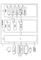
- FIG. 1 is a block diagram showing an example of an automatic driving control system including a mode switching control device according to an embodiment of the present invention.
- FIG. 2 is a functional block diagram showing an example of the mode switching control device 6 shown in FIG.
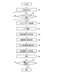
- FIG. 3 is a flowchart showing an example of a processing procedure of the mode switching control device 6 shown in FIG.
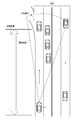
- FIG. 4 is a diagram illustrating an example of the vehicle distribution around the switching section.
- FIG. 5 is a diagram illustrating an example of the recommended degree distribution in the situation illustrated in FIG. 4.
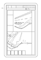
- FIG. 6 is a diagram illustrating an example of a navigation screen displayed on the display unit 9.
- FIG. 7 is a diagram illustrating another example of the vehicle distribution and the recommendation degree distribution around the switching section.
- FIG. 1 is a block diagram showing an example of an automatic driving control system including a mode switching control device according to an embodiment of the present invention.
- FIG. 2 is a functional block diagram showing an example of the mode switching control device 6 shown in FIG.
- FIG. 3 is
- FIG. 8 is a diagram illustrating another example of the navigation screen displayed on the display unit 9.
- FIG. 9 is a flowchart showing another example of the processing procedure of the mode switching control device 6 shown in FIG.
- FIG. 10 is a diagram illustrating an example of an image captured in the field of view of the front monitoring camera 11.
- FIG. 11 is a diagram illustrating an example of a voice message output from the speaker 10.
- FIG. 12 is a diagram illustrating another example of the voice message output from the speaker 10.
- FIG. 1 is a block diagram showing an example of an automatic driving control system including a mode switching control device according to an embodiment of the present invention.
- This automatic driving control system is mounted on the vehicle 1.
- the vehicle 1 can travel in either the manual operation mode or the automatic operation mode.
- the vehicle 1 includes a power unit 2 and a steering device 3 as basic equipment.
- the power unit 2 includes a power source and a transmission.
- As the power source an internal combustion engine, an electric motor, or both can be used.
- the steering device 3 is connected to the steering wheel 4.
- the manual driving mode is a mode in which the vehicle 1 is driven mainly by a driver's manual driving operation, for example.
- the manual driving mode includes, for example, an operation mode in which the vehicle travels based only on the driving operation of the driver, and an operation mode in which driving operation support control is performed to assist the driving operation of the driver while mainly driving the driving operation of the driver. May be included.
- the driving operation support control assists the steering operation by the driver when the vehicle 1 is traveling on a curve, and assists the driving operation of the vehicle so as to travel along the curvature of the curve.
- the driving operation support control includes control for assisting the driver's accelerator operation (for example, operation of the accelerator pedal) or brake operation (for example, operation of the brake pedal), manual steering (manual operation of steering), and manual speed adjustment (speed adjustment). Manual operation) or the like.
- Manual steering is to operate the traveling direction of the vehicle 1 mainly by the driver's operation of the steering wheel 4.
- the manual speed adjustment is to adjust the speed of the vehicle mainly based on the driver's accelerator operation or brake operation.
- the automatic operation mode is a mode that realizes an operation state in which the vehicle automatically travels along the road, for example.
- the automatic driving mode may include, for example, a driving state in which the vehicle automatically travels toward a preset destination without driving by the driver. In the automatic driving mode, it is not always necessary to control all the behaviors of the vehicle.
- the automatic driving mode may include a driving state in which the driving operation of the driver is reflected on the traveling of the vehicle within a preset allowable range.
- the automatic operation control device 5 in FIG. 1 executes operation control in the automatic operation mode.
- the automatic driving control device 5 acquires sensing data from the accelerator pedal sensor 12, the brake pedal sensor 13, the GPS receiver 15, and the vehicle speed sensor 16, respectively. And these sensing data, the digital map data 14a memorize
- Automatic control includes, for example, automatic steering (automatic steering operation) and automatic speed adjustment (automatic driving of speed).
- Automatic steering is an operating state in which the steering device 3 is automatically controlled.
- Automatic steering includes LKA (Lane Keeping Assist).
- LKA Li Keeping Assist
- the LKA automatically controls the steering device 3 so that the vehicle 1 does not deviate from the traveling lane even when the driver does not perform the steering operation.
- the driver's steering operation may be reflected in the steering of the vehicle in a range where the vehicle 1 does not deviate from the travel lane (allowable range).
- automatic steering is not limited to LKA.
- Automatic speed adjustment is an operating state in which the speed of the vehicle 1 is automatically controlled.
- Automatic speed adjustment includes ACC (Adaptive Cruise Control). For example, when there is no preceding vehicle ahead of the vehicle 1, the ACC performs constant speed control that causes the vehicle 1 to travel at a constant speed at a preset speed. Further, when a preceding vehicle is present in front of the vehicle 1, the ACC performs follow-up control for adjusting the vehicle speed of the vehicle 1 according to the inter-vehicle distance from the preceding vehicle.
- ACC Adaptive Cruise Control
- the automatic operation control device 5 decelerates the vehicle 1 according to the driver's brake operation (for example, operation of the brake pedal) even when ACC is being executed.
- the automatic operation control device 5 can perform the driver's accelerator operation (for example, accelerator) up to a preset maximum allowable speed (for example, the maximum speed legally determined on the traveling road) even during execution of ACC.
- the vehicle can be accelerated according to the pedal operation.
- the automatic speed adjustment is not limited to ACC but also includes CC (Cruise Control).
- the automatic operation control system in this embodiment includes a mode switching control system 100.
- the mode switching control system 100 controls mode switching for switching the driving mode of the vehicle.
- the mode switching control system 100 includes a mode switching control device 6 as a computer that controls mode switching.
- switching from the automatic operation mode to the manual operation mode will be described.
- the mode switching control system 100 includes an in-vehicle radar 8, a front monitoring camera 11, a display unit 9, and a speaker 10.
- the in-vehicle radar 8 as an example of a sensor that monitors the periphery of the vehicle 1 radiates a radio wave (radar wave) in the GHz band toward the front of the vehicle 1, for example, and receives an echo thereof. Based on the time from the transmission of the radar wave to the reception of the echo, the distance to the object in the radar detection area can be measured. If the wavelength of the echo is measured, the relative speed between the vehicle 1 and the object can be measured.
- Such basic signal processing is performed in the in-vehicle radar 8, and radar data as an example of sensing data is generated. Radar data including the distance to the object, relative speed, radio wave reflector degree, etc. is passed to the mode switching control device 6.
- the front monitoring camera 11 as an example of a sensor that monitors the periphery of the vehicle 1 is attached, for example, to the innermost part of the windshield with the field of view directed in the traveling direction of the vehicle 1. For example, the front monitoring camera 11 captures an area up to several hundred meters ahead of the vehicle 1 and performs image processing to obtain video data. Video data as an example of sensing data related to the object is passed to the mode switching control device 6.
- the display unit 9 as an example of a display is a human machine interface between a passenger including a driver and the mode switching control device 6, and displays a map around the vehicle, various information, messages, and the like.
- the speaker 10 is also one of this type of interface, and outputs a voice message.
- the mode switching control system 100 may be connected to the driver camera 7.
- the driver camera 7 is disposed at a place where the driver can be imaged, for example, on a dashboard, and images the inside of the vehicle including the driver.
- the generated video signal is output to the mode switching control device 6.
- FIG. 2 is a functional block diagram showing an example of the mode switching control device 6.
- the mode switching control device 6 includes a control unit 61, an I / O (input / output interface) 62, and a storage unit 63.
- the I / O 62 acquires radar data from the in-vehicle radar 8 and acquires video data from the front monitoring camera 11. These data are stored in the storage unit 63 (radar data 63a, video data 63b). Further, the I / O 62 acquires the digital map data 14 a at the address instructed from the control unit 61 from the storage device 14 and holds it in the storage unit 63. Further, the I / O 62 passes the display image data to the display unit 9 to display a desired image, and transfers the audio signal data to the speaker 10 for loud output.
- the control unit 61 has a CPU (Central Processing Unit) and a memory constituting the computer.
- the control unit 61 includes an acquisition unit 61a, a calculation unit 61b, and a notification control unit 61c as control functions necessary for carrying out this embodiment. These control functions are realized by the CPU executing a program written in the memory.
- the acquisition unit 61a is realized by causing a computer to execute a command for acquiring sensing data indicating a surrounding situation in a switching section set for mode switching from a sensor that monitors the periphery of the vehicle 1. It is a function.
- the calculation unit 61b is a processing function realized by causing a computer to execute a command for calculating a recommended mode switching position that is a recommended position for mode switching in a switching section based on sensing data.
- the notification control unit 61c is a processing function realized by causing the computer to execute a command for notifying the driver of the vehicle 1 of the recommended mode switching position.
- the obtaining unit 61a obtains sensing data indicating the surrounding situation of the vehicle 1 from a sensor that monitors the surroundings of the vehicle 1. That is, the acquisition unit 61 a acquires the radar data 63 a from the in-vehicle radar 8 and stores it in the storage unit 63. In particular, the acquisition unit 61a acquires the radar data 63a in the switching section from the in-vehicle radar 8 when the operation mode of the vehicle 1 is switched from the automatic operation mode to the manual operation mode.
- the switching section means, for example, a section that is set in advance for mode switching before the exit of the nearest interchange of the destination when traveling on an expressway.
- the calculation unit 61b calculates a recommended mode switching position, which is a recommended position for mode switching in the switching section, based on the acquired radar data 63a. That is, the calculation unit 61b processes the radar data 63a to calculate the distribution state of objects around the vehicle 1.
- the vehicle distribution data 63c created by this processing is stored in the storage unit 63. Then, the calculation unit 61b uses the object distribution status indicated in the vehicle distribution data 63c as a criterion for calculating the recommended mode switching position. For example, the position where the object distribution density is the sparsest in the switching section can be set as the mode switching recommended position. The position where the distribution density of the object is sparse can be understood as the position farthest from the obstacle.
- the mode switching recommended position in the embodiment is a position at which mode switching can be most safely executed. For example, if mode switching is executed at a position farthest from the obstacle, it is considered safest. Originally, mode switching can be executed anywhere within the switching section, but the embodiment searches for a safer position among them.
- the recommended mode switching position can be expressed numerically as, for example, latitude and longitude, or position coordinates in the XY coordinate system.
- Mode switching recommended position data 63d obtained by digitizing the mode switching recommended position is stored in the storage unit 63.
- the safe position is not limited to the recommended mode switching position, but is considered to be distributed in the switching section with a certain extent. Accordingly, the calculation unit 61b calculates a distribution of an index (hereinafter, abbreviated as a recommendation level) obtained by quantifying the degree of recommendation of mode switching in the switching section as, for example, an inverse number of the vehicle distribution data 63c.
- a recommendation level an index obtained by quantifying the degree of recommendation of mode switching in the switching section as, for example, an inverse number of the vehicle distribution data 63c.
- the notification control unit 61c performs control for notifying the driver of the vehicle 1 of the calculated mode switching recommended position. For example, the notification control unit 61c visually notifies the driver of the recommended mode switching position by creating image data in which the recommended mode switching position is superimposed on the map image around the vehicle 1 and displaying the image data on the display unit 9. To do.
- a map image around the vehicle 1 can be obtained by reading out map data corresponding to the position information of the vehicle 1 output from the GPS receiver 15 from the digital map data 14a.
- the notification control unit 61c creates display image data 63e by superimposing an icon indicating the recommended mode switching position on the coordinates corresponding to the recommended mode switching position of the map data.
- the display image data 63e is stored in the storage unit 63.
- the notification control unit 61c creates a color map (heat map) image in which the recommendation value is mapped to the display color, and stores the display image data 63e in the storage unit 63.
- the notification control unit 61 c reads the display image data 63 e from the storage unit 63 and displays it on the display unit 9.
- the storage unit 63 stores radar data 63a, video data 63b, vehicle distribution data 63c, recommended mode switching position data 63d, and display image data 63e.
- the storage unit 63 is a semiconductor memory such as RAM (Random Access Memory), ROM (Read Only Memory), flash memory, SDRAM (Synchronous Dynamic RAM), EPROM (Erasable Programmable ROM), EPROM (Electrically Erasable Programmable ROM), or the like. Or a storage medium such as SSD (Solid State Drive) or HDD (Hard Disk Drive). Alternatively, it may be a storage area provided inside a one-chip microcomputer such as FPGA (Field Programmable Gate Array) or PIC (Peripheral Interface Controller). Next, the operation and effect of the present invention will be described based on the above configuration.
- FIG. 3 is a flowchart showing an example of a processing procedure of the mode switching control device 6 shown in FIG.
- the vehicle is going down from a highway to a general road, and it is assumed that mode switching is executed within a switching section set in advance before the interchange, for example.
- step S1 when a destination is set using, for example, a navigation system (not shown) (step S1), the mode switching control device 6 waits for an approach to an interchange on the route (step S2). When the approach to the interchange is recognized (step S2: Yes), the mode switching control device 6 acquires radar data generated by the in-vehicle radar 8 (step S3), and performs data analysis processing (step S4).
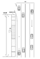
- FIG. 4 is a diagram showing an example of the vehicle distribution around the switching section.
- the detection area of the in-vehicle radar 8 of the vehicle 1 is assumed to be wide enough to sufficiently cover the switching section set before getting off from the highway HWY to the general road R.
- the mode switching control device 6 Prior to entering the switching section, also in the switching section, the mode switching control device 6 analyzes the radar data from the in-vehicle radar 8 and calculates the distribution of surrounding vehicles (step S5 in FIG. 3). The result is stored as vehicle distribution data 63c.
- vehicle distribution data 63c For example, in the situation shown in FIG. 4, it can be seen that the distribution density of the vehicles around the vehicle distribution data 63c is high near the end of the switching section and low near the start of the switching section.
- FIG. 5 is a diagram showing an example of the recommended degree distribution in the situation shown in FIG.
- the degree of recommendation is an index obtained by quantifying the degree of recommendation of mode switching in the switching section, and the distribution is calculated as, for example, the reciprocal of the vehicle distribution data 63c. Then, the recommendation degree in the case of FIG. 4 becomes a distribution “high near the start of the switching section and low as it reaches the final stage”. When the level of recommendation is indicated by shades of hatching, a distribution as shown in FIG. 5 is obtained.
- the mode switching control device 6 identifies the position with the highest recommended degree value as the recommended mode switching position (step S7).
- the mode switching recommended position is shown, for example, as a symbol icon 200 (FIG. 5).
- the mode switching control device 6 synthesizes, for example, a strip-shaped color map in which the recommendation value is mapped to the display color with the latest digital map data 14a read from the storage device 14, and creates display image data 63e. (Step S8).
- the created display image data 63e is immediately displayed on the display unit 9 (step S9).
- step S9 The procedure from step S3 to step S9 is repeated at a cycle corresponding to the display update cycle of the display unit 9 until the operation mode is switched from the automatic operation mode to the manual operation mode (step S10).
- the acquisition of the sensing data in step S3 can be performed concurrently with the processing in other steps, and the order of the processing shown in each step is not limited to FIG.
- FIG. 6 is a diagram showing an example of a navigation screen displayed on the display unit 9.
- a strip graph corresponding to the switching section (corresponding to FIG. 5) and a symbol icon 200 indicating the recommended mode switching position appear on the right end of the navigation screen, for example.
- the driver can determine at which position in the switching section the mode switching should be performed. According to FIG. 6, it can be seen that it is safer to complete the mode switching earlier when entering the switching section.
- FIG. 7 is a diagram illustrating another example of the vehicle distribution around the switching section. Compared with FIG. 4 and FIG. 5, it can be seen that there are other vehicles on the right side of the vehicle 1 and near the end of the switching section, but there are few vehicles in the center of the switching section. In accordance with this, the recommendation level increases near the center of the switching section, and the mode switching recommended position is also calculated near the center. Reflecting this, the navigation screen is displayed as shown in FIG. 8, for example, and it is understood that it is safer for the driver to perform mode switching near the center of the switching section.
- the acquisition unit 61a acquires radar data from the in-vehicle radar 8 and passes it to the calculation unit 61b.
- the calculating unit 61b analyzes the radar data to obtain the distribution of other vehicles around the vehicle 1, and calculates the mode switching recommendation degree distribution and the mode switching recommended position based on the result.
- the notification control unit 61c creates a color map image in which the recommended degree distribution is associated with the display color and displays the color map image on the display unit 9.
- the operation mode can be switched at an appropriate position, thereby providing a mode switching control device, a mode switching control system, a mode switching control method, and a program that improve safety. can do.
- the recommended mode switching position is calculated based on the radar data obtained by the in-vehicle radar 8.
- the recommended mode switching position is calculated based on video data captured by the front monitoring camera 11.
- the mode is switched within the switching section set near the interchange on the expressway.
- the driver performs the mode switching within the switching section set by displaying the intention of mode switching.
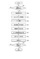
- FIG. 9 is a flowchart illustrating an example of a processing procedure of the mode switching control device 6 according to the second embodiment.
- the mode switching control device 6 waits for a driving mode switching request (intention display) from the driver. For example, when there is a request for switching to the manual operation mode in the automatic operation mode (step S21: Yes), the mode switching control device 6 sets, for example, a section of several hundred meters in front of the vehicle as a switching section for mode switching. (Step S2).
- the mode switching control device 6 acquires video data generated by the front monitoring camera 11 (step S23), and performs data analysis processing (step S24).
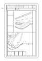
- FIG. 10 is a diagram illustrating an example of an image captured in the field of view of the front monitoring camera 11.
- a known image processing technique it is possible to individually identify objects in the field of view and know the distribution status of each object.
- OpenCV Open Source Computer Computer Vision Library
- more accurate data can be generated by developing a library specialized for image analysis for vehicles.
- step S25 When the distribution of surrounding vehicles is calculated (step S25). The result is stored as vehicle distribution data 63c. Then, similarly to the first embodiment, the mode switching control device 6 calculates the distribution of the recommended degree of mode switching based on the vehicle distribution data 63c (step S26), and recommends the mode switching with the highest recommended position value. The position is specified (step S27).
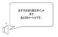
- the mode switching control device 6 creates a voice message for notifying the driver of the recommended mode switching position (step S28), and outputs a loud voice from the speaker 10 (step S29).
- the distance from the current position of the vehicle 1 to the recommended mode switching position may be calculated and a voice message “500 meters to the recommended switching point” may be sent.
- the distance from the current position of the vehicle 1 to the recommended mode switching position is divided by the current vehicle speed to calculate the time required to reach the recommended mode switching position. You may make it voice
- step S30 the procedure of step S28 and step S29 may be repeated at a relatively long interval such as 10 seconds. . This is because if a voice message is output in a too short period of time, the driver may be given psychological pressure. Also in FIG. 9, the acquisition and analysis of the video data may be performed simultaneously with the processing in other steps.
- the calculation unit 61b sets a switching section in front of the vehicle, and the front monitoring camera 11 And the distribution of other vehicles around the vehicle 1 is obtained. If the distribution of surrounding vehicles is known, the calculation unit 61b calculates the mode switching recommendation degree distribution and the mode switching recommended position. The notification control unit 61c notifies the driver of the recommended mode switching position by voice.
- the mode switching recommended position is notified by voice.
- the notification by voice can be expected to have an effect different from the visual notification, for example, if the volume is increased, the driver is awakened.
- the recommended mode switching position is calculated based on the video data obtained by the front monitoring camera 11. As a result, it is possible to obtain a resolution that cannot be obtained by radio wave radar and to calculate a more precise position. That is, according to the second embodiment, the operation mode can be switched at an appropriate position, thereby providing a mode switching control device, a mode switching control system, a mode switching control method, and a program for improving safety. be able to.
- the present invention is not limited to the above embodiment.
- the mode switching recommendation degree distribution and the mode switching are used.
- the recommended position can also be calculated. In this manner, by integrally handling data from different types of sensors (sensor fusion), it is possible to obtain effects such as improvement in accuracy and mutual complementation.
- the in-vehicle radar 8 when a large vehicle (such as a truck) appears just before the direction of travel, the field of view may be blocked by the front monitoring camera 11 alone. Therefore, by using the in-vehicle radar 8 together, sensing utilizing characteristics such as diffraction / reflection of radio waves can be performed, and video data can be interpolated. For example, if the weight of radar data is increased during night driving and the weight of video data is increased during stormy weather, the distribution of surrounding objects can be calculated more accurately while taking into account the mutual propagation characteristics of light and radio waves. It becomes possible to do. Furthermore, it is of course possible to use other sensors such as an ultrasonic radar.
- a plurality of front monitoring cameras 11 may be attached.
- one front monitoring camera 11 is attached to each of the right side and the left side of the vehicle 1, a wide field of view can be secured with both cameras, and the field of view can be prevented from being lost due to an unexpected interruption of another vehicle.
- depth information can be acquired by the principle of a so-called stereo camera, and the distance to an object in the field of view can be accurately measured.
- the number of cameras is not limited to two, and more cameras (image sensors) can be used.
- the mode switching control device 6 can be provided as a built-in dedicated hardware device, or can be implemented as a function provided in an existing in-vehicle device (for example, a car navigation device).
- safety is further improved, including whether to make a voice announcement or not.
- a technology that numerically evaluates the driver's condition from the driver's video data captured by the driver camera 7 safety is further improved, including whether to make a voice announcement or not.
- the apparatus of the present invention can be realized by a computer and a program, and the program can be recorded on a recording medium or provided through a network.
- each of the above devices and their device parts can be implemented with either a hardware configuration or a combined configuration of hardware resources and software.
- the software of the combined configuration a program for causing the computer to realize the functions of each device by being installed in a computer from a network or a computer-readable recording medium in advance and executed by a processor of the computer is used.
- processor or “hardware processor” used in connection with a computer are, for example, CPU, GPU (GraphicsGraphProcessing Unit), ASIC (Application Specific IntegratedcuCircuit), SPLD (Simple Programmable Logic Device), CPLD ( Complex Programmable Logic Device), or a circuit such as FPGA.
- CPU CPU
- GPU GraphicsGraphProcessing Unit
- ASIC Application Specific IntegratedcuCircuit
- SPLD Simple Programmable Logic Device
- CPLD Complex Programmable Logic Device
- FPGA Complex Programmable Logic Device
- the processor reads out and executes the program stored in the memory, thereby realizing a specific function based on the program.
- the program may be directly incorporated in the processor circuit.
- the processor realizes its function by reading and executing a program incorporated in the circuit.
- the vehicle type, the function of the automatic driving control device, the control function and control procedure of the mode switching control device, and the control contents can be variously modified and implemented without departing from the gist of the present invention.
- the present invention is not limited to the above-described embodiment as it is, and can be embodied by modifying the constituent elements without departing from the scope of the invention in the implementation stage.
- various inventions can be formed by appropriately combining a plurality of constituent elements disclosed in the embodiment. For example, some components may be deleted from all the components shown in the embodiment. Furthermore, you may combine suitably the component covering different embodiment.
- a mode switching control device for controlling mode switching for switching a driving mode of a vehicle between a manual driving mode and an automatic driving mode comprising a hardware processor and a memory
- the hardware processor is Sensing data indicating a surrounding situation in a switching section set for mode switching is acquired from a sensor that monitors the periphery of the vehicle, Based on the sensing data, calculate a mode switching recommended position that is a recommended position for the mode switching in the switching section, A mode switching control device configured to store position information of the calculated mode switching recommended position in the memory.
- a mode switching control system that controls mode switching for switching a driving mode of a vehicle between a manual driving mode and an automatic driving mode, and monitors the periphery of the vehicle and outputs sensing data indicating a surrounding state of the vehicle
- a sensor a hardware processor, and a memory
- the hardware processor is Sensing data indicating the surrounding situation in the switching section set for the mode switching is acquired from the sensor, Based on the sensing data, calculate a mode switching recommended position that is a recommended position for the mode switching in the switching section,
- a mode switching control system configured to store position information of the calculated mode switching recommended position in the memory.
- a mode switching control method for controlling a mode switching for switching a driving mode of a vehicle between a manual driving mode and an automatic driving mode by a computer Using at least one hardware processor to obtain sensing data indicating surrounding conditions in a switching section set for mode switching from a sensor that monitors the surroundings of the vehicle;
- a mode switching control method comprising: using at least one hardware processor and calculating a mode switching recommended position, which is a recommended position for mode switching in the switching section, based on the sensing data.
Landscapes
- Engineering & Computer Science (AREA)
- Automation & Control Theory (AREA)
- Physics & Mathematics (AREA)
- Mechanical Engineering (AREA)
- General Physics & Mathematics (AREA)
- Theoretical Computer Science (AREA)
- Human Computer Interaction (AREA)
- Transportation (AREA)
- Radar, Positioning & Navigation (AREA)
- Remote Sensing (AREA)
- Business, Economics & Management (AREA)
- Educational Technology (AREA)
- Educational Administration (AREA)
- Mathematical Physics (AREA)
- Traffic Control Systems (AREA)
- Control Of Driving Devices And Active Controlling Of Vehicle (AREA)
- Aviation & Aerospace Engineering (AREA)
- Instructional Devices (AREA)
- Navigation (AREA)
Priority Applications (3)
| Application Number | Priority Date | Filing Date | Title |
|---|---|---|---|
| CN201780062820.5A CN109844841A (zh) | 2017-03-09 | 2017-09-13 | 模式切换控制装置、模式切换控制系统、模式切换控制方法及程序 |
| DE112017007205.0T DE112017007205T5 (de) | 2017-03-09 | 2017-09-13 | Modusumschaltsteuergerät, Modusumschaltsteuerungssystem, Modusumschaltsteuerverfahren und Programm |
| US16/384,375 US20190243360A1 (en) | 2017-03-09 | 2019-04-15 | Mode switch controller, mode switch control system, mode switch control method, and program |
Applications Claiming Priority (2)
| Application Number | Priority Date | Filing Date | Title |
|---|---|---|---|
| JP2017-045137 | 2017-03-09 | ||
| JP2017045137A JP2018147450A (ja) | 2017-03-09 | 2017-03-09 | モード切替制御装置、モード切替制御システム、モード切替制御方法およびプログラム |
Related Child Applications (1)
| Application Number | Title | Priority Date | Filing Date |
|---|---|---|---|
| US16/384,375 Continuation US20190243360A1 (en) | 2017-03-09 | 2019-04-15 | Mode switch controller, mode switch control system, mode switch control method, and program |
Publications (1)
| Publication Number | Publication Date |
|---|---|
| WO2018163472A1 true WO2018163472A1 (ja) | 2018-09-13 |
Family
ID=63447376
Family Applications (1)
| Application Number | Title | Priority Date | Filing Date |
|---|---|---|---|
| PCT/JP2017/033147 WO2018163472A1 (ja) | 2017-03-09 | 2017-09-13 | モード切替制御装置、モード切替制御システム、モード切替制御方法およびプログラム |
Country Status (5)
Families Citing this family (8)
| Publication number | Priority date | Publication date | Assignee | Title |
|---|---|---|---|---|
| US11137757B2 (en) * | 2018-03-23 | 2021-10-05 | Ford Global Technologies, Llc | Method and apparatus for selective drive-mode enablement |
| JP7067435B2 (ja) * | 2018-11-16 | 2022-05-16 | トヨタ自動車株式会社 | 軌道生成装置 |
| DE102020000710A1 (de) | 2020-02-04 | 2021-08-05 | Daimler Ag | Videosystem und Verfahren zum Darstellen eines Videos eines Transportmittels |
| JP7524806B2 (ja) * | 2021-03-24 | 2024-07-30 | トヨタ自動車株式会社 | 車両制御装置、車両制御用コンピュータプログラム及び車両制御方法 |
| TWI792381B (zh) * | 2021-03-25 | 2023-02-11 | 鈺立微電子股份有限公司 | 影像擷取裝置及其深度資訊計算方法 |
| JP7530694B2 (ja) * | 2021-03-26 | 2024-08-08 | パナソニックオートモーティブシステムズ株式会社 | 支援装置 |
| CN113895458B (zh) * | 2021-10-26 | 2023-06-30 | 上海集度汽车有限公司 | 车辆驾驶行为的管理方法、装置、车辆及存储介质 |
| CN114435407A (zh) * | 2022-03-24 | 2022-05-06 | 广州小鹏自动驾驶科技有限公司 | 一种车辆控制方法、装置及车辆 |
Citations (2)
| Publication number | Priority date | Publication date | Assignee | Title |
|---|---|---|---|---|
| JP2016200931A (ja) * | 2015-04-09 | 2016-12-01 | 三菱電機株式会社 | 運転支援装置および運転支援方法 |
| JP2017032441A (ja) * | 2015-08-03 | 2017-02-09 | アイシン・エィ・ダブリュ株式会社 | 走行支援システム、走行支援方法及びコンピュータプログラム |
Family Cites Families (3)
| Publication number | Priority date | Publication date | Assignee | Title |
|---|---|---|---|---|
| JP2013242615A (ja) * | 2012-05-17 | 2013-12-05 | Denso Corp | 運転シーン遷移予測装置および車両用推奨運転操作提示装置 |
| DE102013012779A1 (de) * | 2013-07-31 | 2015-02-05 | Valeo Schalter Und Sensoren Gmbh | Verfahren zum Betreiben einer Fahrerassistenzeinrichtung zum autonomen Führen eines Kraftfahrzeugs und Kraftfahrzeug |
| JP6531983B2 (ja) * | 2015-07-31 | 2019-06-19 | パナソニックIpマネジメント株式会社 | 自動運転装置、自動運転支援方法及び自動運転支援プログラム |
-
2017
- 2017-03-09 JP JP2017045137A patent/JP2018147450A/ja active Pending
- 2017-09-13 WO PCT/JP2017/033147 patent/WO2018163472A1/ja active Application Filing
- 2017-09-13 CN CN201780062820.5A patent/CN109844841A/zh active Pending
- 2017-09-13 DE DE112017007205.0T patent/DE112017007205T5/de active Pending
-
2019
- 2019-04-15 US US16/384,375 patent/US20190243360A1/en not_active Abandoned
Patent Citations (2)
| Publication number | Priority date | Publication date | Assignee | Title |
|---|---|---|---|---|
| JP2016200931A (ja) * | 2015-04-09 | 2016-12-01 | 三菱電機株式会社 | 運転支援装置および運転支援方法 |
| JP2017032441A (ja) * | 2015-08-03 | 2017-02-09 | アイシン・エィ・ダブリュ株式会社 | 走行支援システム、走行支援方法及びコンピュータプログラム |
Also Published As
| Publication number | Publication date |
|---|---|
| US20190243360A1 (en) | 2019-08-08 |
| DE112017007205T5 (de) | 2019-11-21 |
| JP2018147450A (ja) | 2018-09-20 |
| CN109844841A (zh) | 2019-06-04 |
Similar Documents
| Publication | Publication Date | Title |
|---|---|---|
| JP6648721B2 (ja) | 支援装置、支援方法およびプログラム | |
| WO2018163472A1 (ja) | モード切替制御装置、モード切替制御システム、モード切替制御方法およびプログラム | |
| JP7067067B2 (ja) | 信号機認識装置、及び自動運転システム | |
| JP7029910B2 (ja) | 情報処理装置、情報処理方法及びプログラム | |
| JP7480894B2 (ja) | 車両用表示装置 | |
| US10197414B2 (en) | Vehicle display control device and vehicle display control method | |
| JP6591087B2 (ja) | 表示制御装置、表示装置および表示制御方法 | |
| US11548443B2 (en) | Display system, display method, and program for indicating a peripheral situation of a vehicle | |
| US20180024354A1 (en) | Vehicle display control device and vehicle display unit | |
| WO2019008764A1 (ja) | 駐車支援方法及び駐車支援装置 | |
| JP2018133072A (ja) | 情報処理装置およびプログラム | |
| JP2017151041A (ja) | 走行支援装置及びセンタ | |
| JP6969509B2 (ja) | 車両用表示制御装置、車両用表示制御方法、及び制御プログラム | |
| CN110888431B (zh) | 通知系统、通知控制方法及存储介质 | |
| JP2017166913A (ja) | 表示制御装置及び表示制御方法 | |
| WO2022039021A1 (ja) | 車両用渋滞判断装置、および車両用表示制御装置 | |
| WO2022168540A1 (ja) | 表示制御装置及び表示制御プログラム | |
| US20230418541A1 (en) | Vehicle display system, display system, display method, and non-transitory computer readable storage medium | |
| CN113401056B (zh) | 显示控制装置、显示控制方法以及计算机可读取存储介质 | |
| US11447154B2 (en) | Vehicle travel system | |
| US20210018934A1 (en) | Travel control device, travel system, and travel program | |
| JP7302311B2 (ja) | 車両用表示制御装置、車両用表示制御方法、車両用表示制御プログラム | |
| JP7310851B2 (ja) | 車両用表示装置 | |
| US11760389B2 (en) | Vehicle controller device and vehicle control system | |
| JP2018169945A (ja) | 運転支援装置、運転支援方法及び運転支援プログラム |
Legal Events
| Date | Code | Title | Description |
|---|---|---|---|
| DPE2 | Request for preliminary examination filed before expiration of 19th month from priority date (pct application filed from 20040101) | ||
| 121 | Ep: the epo has been informed by wipo that ep was designated in this application |
Ref document number: 17900103 Country of ref document: EP Kind code of ref document: A1 |
|
| 122 | Ep: pct application non-entry in european phase |
Ref document number: 17900103 Country of ref document: EP Kind code of ref document: A1 |