WO2018159586A1 - 充電装置、充電方法およびプログラム - Google Patents
充電装置、充電方法およびプログラム Download PDFInfo
- Publication number
- WO2018159586A1 WO2018159586A1 PCT/JP2018/007162 JP2018007162W WO2018159586A1 WO 2018159586 A1 WO2018159586 A1 WO 2018159586A1 JP 2018007162 W JP2018007162 W JP 2018007162W WO 2018159586 A1 WO2018159586 A1 WO 2018159586A1
- Authority
- WO
- WIPO (PCT)
- Prior art keywords
- charging
- terminal device
- power supply
- control unit
- history
- Prior art date
- Legal status (The legal status is an assumption and is not a legal conclusion. Google has not performed a legal analysis and makes no representation as to the accuracy of the status listed.)
- Ceased
Links
Images





Classifications
-
- H—ELECTRICITY
- H02—GENERATION; CONVERSION OR DISTRIBUTION OF ELECTRIC POWER
- H02J—ELECTRIC POWER NETWORKS; CIRCUIT ARRANGEMENTS OR SYSTEMS FOR SUPPLYING OR DISTRIBUTING ELECTRIC POWER; SYSTEMS FOR STORING ELECTRIC ENERGY
- H02J7/00—Circuit arrangements for charging or discharging batteries or for supplying loads from batteries
- H02J7/02—Circuit arrangements for charging or discharging batteries or for supplying loads from batteries for charging batteries from AC mains by converters
Definitions
- Some embodiments of the present invention relate to a charging device, a charging method, and a program.
- Charging devices that are installed in public places, operate with natural energy such as sunlight, and supply power to user devices are known for use during disasters.
- the charging device disclosed in Patent Document 1 is a device in which a user charges a device by connecting the device to the charging device installed in a public place.
- the charging device cannot fulfill its original purpose of providing a charging service to as many users as possible, and there is a problem that convenience for the user is impaired.
- One embodiment of the present invention has been made in view of the above points, and an object thereof is to provide a charging device, a charging method, and a program capable of improving user convenience.
- One aspect of the present invention is made to solve the above-described problem, and one aspect of the present invention includes a power supply unit that supplies power to a terminal device, a communication unit that communicates with the terminal device, and a control.
- the control unit identifies a charging history of the terminal device based on terminal information acquired from the terminal device via the communication unit with reference to a database holding a charging history, and the charging The charging device controls power supply to the terminal device by the power supply unit based on a history.
- One embodiment of the present invention refers to a power supply step for supplying power to a terminal device, a communication step for communicating with the terminal device, and a database that holds a charging history.
- a charging method comprising: specifying a charging history of the terminal device based on acquired terminal information; and controlling power supply to the terminal device in the power supply step based on the charging history.
- One embodiment of the present invention refers to a power supply procedure for supplying power to a terminal device to a computer of a charging device, a communication procedure for communicating with the terminal device, and a database that holds a charging history.
- a procedure for specifying a charging history of the terminal device based on terminal information acquired from the terminal device by a procedure, and a procedure for controlling power supply to the terminal device in the power supply procedure based on the charging history are executed. It is a program for.
- FIG. 1 is a block diagram showing a configuration of a charging system 1 according to the first embodiment of the present invention.
- the charging system 1 includes a charging device 10 and a terminal device 20 used by a user.
- the terminal device 20 is a portable electronic device such as a mobile phone, a smartphone, or a tablet, for example.
- the charging device 10 and the terminal device 20 are connected by a charging cable 30.
- the charging device 10 and the terminal device 20 are connected by, for example, USB (Universal Serial Bus). In that case, the terminal device 20 is also referred to as a USB device.
- USB Universal Serial Bus
- the charging device 10 includes a USB control unit 100, a power supply unit 104, a storage unit 105, a main control unit 107, a server I / F 109, and a notification unit 110.
- the USB control unit 100 includes a USB terminal 101, a charge control unit 102, and a USB controller 103 as functional units.
- the USB terminal 101 is an interface for connecting to the terminal device 20 via the charging cable 30. Since the USB terminal 101 is electrically connected to the terminal device 20 via the charging cable 30, power can be supplied to the terminal device 20.
- the charging cable 30 is removed from the USB terminal 101 or the terminal device 20, the charging device 10 and the terminal device 20 are electrically insulated.
- the USB terminal 101 and the charging cable 30 may be integrated.
- the power supply from the charging device 10 to the terminal device 20 may be performed by a method that does not involve the charging cable 30.
- the power supply from the charging device 10 to the terminal device 20 may be performed by non-contact power feeding (wireless power feeding).
- the charging control unit 102 controls charging for the terminal device 20.
- the charging control unit 102 may control charging based on an instruction from the main control unit 107 described later.
- the USB controller 103 performs USB communication with the terminal device 20 connected to the USB terminal 101.
- the power supply unit 104 is a power source such as a solar cell, a wind power generator, a cogeneration system, or the like.
- the power supply unit 104 may be connected to a commercial power network, or may supply power supplied from the commercial power network to the terminal device 20.
- the storage unit 105 includes, for example, an HDD (Hard Disc Drive), a flash memory, an EEPROM (Electrically Erasable Programmable Read Only Memory), a ROM (Read Only Memory), or a RAM (Random Accel Memory).
- the storage unit 105 stores various information and programs related to the user database 106 and the charging device 10.
- the user database 106 is stored in the storage unit 105 and holds various types of information including user charging history information. Note that the user database 106 may exist in an external server or the like, or may be used in cooperation with an external user database.
- the main control unit 107 controls various functions of the charging device 10. Some or all of the functions of the main control unit 107 may be realized by executing a program stored in the storage unit 105 by a processor such as a CPU (Central Processing Unit) provided in the main control unit 107, for example. Good.
- a processor such as a CPU (Central Processing Unit) provided in the main control unit 107, for example. Good.
- the main control unit 107 includes a database access unit 108 as a functional unit.
- the database access unit 108 accesses the user database 106 and performs processing such as data reference and update.
- the database access unit 108 accesses an external user database via the server I / F 109 when using an external user database.
- the main control unit 107 controls the start and end of charging via the charging control unit 102. Further, the main control unit 107 records the charging history of the terminal device 20 in the user database 106 as charging history information via the database access unit 108. For example, when the charging history for the terminal device 20 does not exist within a predetermined period of the charging history information, the main control unit 107 controls the charging control unit 102 to supply power to the terminal device 20. For example, when the charging history for the terminal device 20 exists within a predetermined period of the charging history information, the main control unit 107 controls the charging control unit 102 and does not supply power to the terminal device 20.
- the server I / F 109 includes a communication interface for performing communication between apparatuses via a wired or wireless network.
- the server I / F may be an Ethernet (registered trademark) interface, or may be a WiFi (registered trademark) (Wireless Fidelity) interface.
- the server I / F 109 communicates with an external server or the like based on the control of the main control unit 107 and the database access unit 108.
- the server I / F 109 may be connected to the main control unit 107 via the USB control unit 100.
- you may comprise the charging device 10 without including server I / F109.
- the notification unit 110 notifies about charging.
- the notification regarding charging is, for example, notification of charging start / end, notification of not charging the connected terminal device 20, and the like.
- the notification unit 110 includes, for example, a display device such as a liquid crystal display or an organic EL (Electro-Luminescence) display, and performs light display using a character display or LED (Light Emitting Diode).
- the notification unit 110 may have a voice output function, and may make a notification regarding charging by voice. Note that the charging device 10 may be configured without including the notification unit 110.
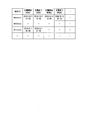
- FIG. 2 is a diagram illustrating an example of charging history information according to the present embodiment.
- the charging history information includes a plurality of records for each terminal ID of the terminal device 20 and stores values such as a charging start time and a charging end time of the terminal device 20.
- the terminal device 20 whose terminal ID is “abcxxxx” is charged from 13:00 on October 1, 2016 to 16:00, and at 10:00 on September 15, 2016. This indicates that charging was performed from 00 minutes to 10:30.
- 3 and 4 are flowcharts showing an example of processing of the charging apparatus 10 according to the present embodiment.
- Step S100 The main control unit 107 determines whether or not the USB controller 103 has detected a connection with a USB device, that is, the terminal device 20. When the USB controller 103 has not detected connection with the terminal device 20 (step S100 / No), the charging device 10 continues the process of step S100. When the USB controller 103 detects a connection with the terminal device 20 (step S100 / Yes), the main control unit 107 controls the USB controller 103 to establish a communication connection with the terminal device 20. Thereafter, the charging apparatus 10 performs the process of step S102.
- Step S ⁇ b> 102 The main control unit 107 controls the USB controller 103 to acquire a Device Descriptor from the terminal device 20 via the USB terminal 101 and the charging cable 30.
- the Device Descriptor is information representing device information, setting information, and the like of the USB device, and is also referred to as terminal information. The Device Descriptor will be described in detail with reference to FIG.
- FIG. 5 is a diagram illustrating an example of information included in the Device Descriptor according to the present embodiment.
- the information included in the Device Descriptor includes, for example, “bLength” representing the size of the Descriptor, “bDescriptorType” representing the type of the Descriptor, “bcdUSB” representing the release number of the USB standard, and the device class.
- the main control unit 107 obtains these values from the terminal device 20, thereby grasping various information related to the connected terminal device 20. For example, the main control unit 107 specifies the charging history of the terminal device 20 included in the charging history information based on these values.
- Step S104 Based on the acquired Device Descriptor, the main control unit 107 determines whether or not the connected terminal device 20 is a device to be charged. For example, when the value of “bDeviceClass” is other than “0” indicating “Interface class”, the main control unit 107 determines that the connected terminal device 20 is not a charging target device. When the value of “bDeviceClass” is “0”, the main control unit 107 may determine that the device is a charging target device, and further obtains an Interface Descriptor representing the interface information of the device from the terminal device 20.
- the main control unit 107 may determine whether or not the device is a charging target device. Further, the main control unit 107 may determine whether or not the device is a charging target device based on values such as “idVendor” and “idProduct”. In addition, the main control unit 107 may determine that the terminal device 20 for which “iSerialNumber” is not individually set is not a charging target device.
- the charging device 10 can identify the connected terminal device 20, and can appropriately select a device to be charged. For example, it is possible to suppress a usage method in which the terminal device 20 is connected to the charging device 10 via a device such as a USB hub to misrepresent an identifier.
- the main control unit 107 may determine that charging is possible regardless of the charging history for the terminal device 20 in which, for example, “iSerialNumber” is not individually set and the charging history cannot be managed, or the maximum charging time is set. Also good.
- the main control unit 107 may change the control based on an instruction from the outside, for example, when a disaster occurs.
- step S104 / Yes the charging device 10 executes the process of step S106. If the main control unit 107 determines that the terminal device 20 is not a chargeable device (step S104 / No), the charging device 10 executes the process of step S118.
- the main control unit 107 generates a terminal ID unique to the terminal based on the acquired Device Descriptor.
- the terminal ID is an identifier used for identifying the terminal device 20 and managing charging history information and the like.
- the main control unit 107 combines the values of “idVendor”, “idProduct”, and “iSerialNumber” based on a predetermined rule to obtain a terminal ID.
- the main control unit 107 may obtain a hash value of a value obtained by combining values of “idVendor”, “idProduct”, and “iSerialNumber” based on a predetermined rule, and may use the hash value as a terminal ID.
- the main control unit 107 may use the value of “iSerialNumber” as the terminal ID, for example.
- the charging apparatus 10 executes the process of step S108.
- Step S108 The database access unit 108 accesses the user database 106, and acquires the charging history information of the user corresponding to the generated terminal ID.
- the main control unit 107 acquires charging history information via the database access unit 108.
- the main control unit 107 specifies and acquires the charging history of the terminal device 20 included in the charging history information based on the terminal information acquired from the terminal device 20.
- the main control unit 107 or the database access unit 108 acquires the charging history information from the external server or the like via the server I / F 109. Then, the charging device 10 performs the process of step S110.
- Step S110 The main control unit 107 calculates the maximum charging time given to the terminal device 20 based on the charging history information.
- the maximum charging time is the maximum time given for one charge. Details of the processing in step S110 will be described later. After that, the charging device 10 executes the process of step S112.
- Step S112 The main control unit 107 determines whether or not the calculated maximum charging time of the terminal device 20 is greater than zero. When the calculated maximum charging time of the terminal device 20 is greater than 0 (step S112 / Yes), the charging device 10 executes the process of step S114. When the maximum charging time of the terminal device 20 is 0 or less (step S112 / No), the charging device 10 executes the process of step S118.
- Step S ⁇ b> 114 The main control unit 107 controls the charging control unit 102 to start charging the terminal device 20.
- the charging control unit 102 causes the power supply unit 104 to start supplying power to the terminal device 20. Thereafter, the charging apparatus 10 performs the process of step S116.
- Step S116 The notification unit 110 notifies the user that charging has started.
- the notification unit 110 performs notification by outputting a voice message, displaying a text message or animation, turning on an LED, or the like.
- the main control unit 107 may notify the user that charging has been started by e-mail or the like.
- the main control unit 107 acquires the user's email address from the user database 106 and requests the external server or the like to send an email via the server I / F 109. Which means is used for notification may be determined based on information included in the Device Descriptor.
- the charging device 10 performs the process of step S120.
- Step S118 In step S104, when the main control unit 107 determines that the terminal device 20 is not a device to be charged (step S104 / No), the notification unit 110 notifies the user that charging cannot be performed.
- the notification means is the same as in step S116, but may be emphasized from the notification in step S116. Thereafter, the charging apparatus 10 executes the process of step S130.
- Step S ⁇ b> 120 The main control unit 107 detects whether or not the terminal device 20 has been removed from the charging device 10 based on whether or not the terminal device 20 is electrically insulated from the USB terminal 101.
- main controller 107 detects removal of terminal device 20 (step S120 / Yes)
- charging device 10 executes the process of step S126.
- main controller 107 does not detect removal of terminal device 20 (step S120 / No)
- charging device 10 executes the process of step S122.
- Step S ⁇ b> 122 The main control unit 107 determines whether charging for the terminal device 20 has been terminated by the trigger from the terminal device 20 via the charging control unit 102.
- charging from the terminal device 20 is terminated, for example, the charging amount of the terminal device 20 reaches full charge or a predetermined charging amount, and charging is terminated. Further, charging may be terminated due to an abnormality in the terminal device 20 or the charging cable 30.
- the main control unit 107 determines that the charging of the terminal device 20 has been completed (step S122 / Yes)
- the charging device 10 executes the process of step S126.
- the main control unit 107 determines that the charging of the terminal device 20 has not been completed (step S122 / No)
- the charging device 10 executes the process of step S124.
- Step S124 The main control unit 107 determines whether or not the charging time for the terminal device 20 is longer than the maximum charging time.
- the charging time is an elapsed time from the timing when charging is started in step S114.
- the charging device 10 executes the process of step S120.
- the main control unit 107 determines that the charging time for the terminal device 20 is longer than the maximum charging time (step S124 / Yes)
- the charging device 10 proceeds to the process of step S126. That is, when the charging from the terminal device 20 is not stopped, the charging to the terminal device 20 is continued unless the charging time exceeds the maximum charging time.
- Step S ⁇ b> 126) The main control unit 107 controls the charging control unit 102 to end the charging of the terminal device 20.
- the charging control unit 102 causes the power supply unit 104 to stop supplying power. After that, the charging device 10 executes the process of step S128.
- Step S128) The notification unit 110 notifies the user that the terminal device 20 is to be removed when a predetermined time has elapsed since the charging of the terminal device 20 is completed.
- the notification unit 110 performs notification by outputting a voice message, displaying a text message or animation, turning on an LED, or the like. Further, notification may be performed by e-mail as in step S116. Thereby, it is possible to prevent the user from continuing to occupy the charging device 10 by keeping the terminal device 20 connected to the charging device 10 even after the end of charging. After that, the charging device 10 executes the process of step S130.
- Step S ⁇ b> 130 The main control unit 107 detects whether or not the terminal device 20 has been removed from the charging device 10 based on whether or not the terminal device 20 is electrically insulated from the USB terminal 101.
- main controller 107 detects removal of terminal device 20 (step S130 / No)
- charging device 10 continues the process of step S130.
- main controller 107 does not detect removal of terminal device 20 (step S130 / Yes)
- charging device 10 executes the process of step S132.
- Step S ⁇ b> 132 The main control unit 107 records charging history information in the user database 106 via the database access unit 108.
- the charge history information includes a charge start time and a charge end time.
- the main control unit 107 records the charging start time and charging end time values in the terminal ID record of the terminal device 20 for the charging history information shown in FIG.
- the main control part 107 does not need to record charge history information, when charge is impossible. Thereafter, the charging apparatus 10 returns to the process of step S100.
- FIG. 6 is a flowchart illustrating an example of the maximum charging time calculation process according to the present embodiment.
- Step S1100 The main control unit 107 accesses the user database 106 via the database access unit 108 and refers to the charging history information.
- the main control unit 107 determines whether the charging history of the terminal device 20 exists in the latest predetermined period using the terminal ID generated in step S106 as a key.
- the predetermined period is a preset period such as one day or one month.
- the charging device 10 executes the process of step S1101.
- the charging device 10 executes the process of step S1102.
- Step S1101 The main control unit 107 sets the maximum charging time of the target terminal device 20 in the charging history information to a predetermined time greater than zero.
- Step S1102 The main control unit 107 sets the maximum charging time of the target terminal device 20 in the charging history information to zero.
- the main control unit 107 controls the supply of power to the terminal device 20 based on whether the charging history of the terminal device 20 exists in the most recent predetermined period.
- the maximum charging time is 0, no time for charging is assigned to the terminal device 20. That is, the terminal device 20 is not charged. Therefore, the charging of the terminal device 20 that has been charged within the most recent predetermined period is prohibited, the occupation of the charging device 10 by the user who tries to charge the terminal device 20 at a high frequency is suppressed, and more users The terminal device 20 can be charged.
- the main control unit 107 may stepwise set a predetermined time to be set as the maximum charging time and a predetermined period used for the determination of the existence of the charging history.
- the first period and the second period longer than the first period are set as the predetermined period used for the determination of the existence of the charging history, and for the terminal device 20 having a charging history within the first period,
- the first maximum charging time is set as the maximum charging time
- a second maximum charging time longer than the first maximum charging time is set. Also good. Thereby, the charging time with respect to the terminal device 20 can be controlled stepwise and flexibly.
- the charging device 10 includes the power supply unit 104 that supplies power to the terminal device 20, the communication unit (USB control unit 100) that communicates with the terminal device 20, and the control unit ( Main control unit 107).
- the control unit (main control unit 107) refers to a database (user database 106) that holds charging history information, and based on the terminal information acquired from the terminal device 20 via the communication unit (USB control unit 100).
- the charging history of the device 20 is specified, and the power supply to the terminal device 20 by the power supply unit 104 is controlled based on the charging history. Thereby, the occupation of the charging device 10 by the user who charges the terminal device 20 with high frequency can be suppressed, and more users can charge the terminal device 20. That is, user convenience can be improved.
- the control unit does not cause the power supply unit 104 to supply power to the terminal device 20 when there is a charging history of the terminal device 20 indicating that charging has been performed within a predetermined period. Thereby, charge with respect to the terminal device 20 of a user with high charge frequency can be prohibited.
- the control unit causes the power supply unit 104 to supply power to the terminal device 20 when there is no charging history of the terminal device 20 indicating that charging has been performed within a predetermined period. Thereby, it can charge with respect to the terminal device 20 of a user with low charge frequency.
- control unit determines whether or not the terminal device 20 is a charging target based on the terminal information, and when determining that the terminal device 20 is not a charging target, the power supply unit 104. Is not allowed to supply power to the terminal device 20. Thereby, the charge to the terminal device 20 which is not charge object can be suppressed, and the opportunity of charge to the terminal device 20 which is charge object can be increased.
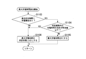
- FIG. 7 is a flowchart illustrating an example of the maximum charging time calculation process according to the present embodiment.
- Step S1103 The main control unit 107 accesses the user database 106 via the database access unit 108 and refers to the charging history information.
- the main control unit 107 determines whether the charging history of the terminal device 20 exists in the latest predetermined period using the terminal ID generated in step S106 as a key.
- step S1103 / Yes the charging device 10 executes the process of step S1104.
- step S1103 / No the charging device 10 executes the process of step S1106.
- Step S1104 The main control unit 107 refers to the charging history information in the user database 106, calculates the total charging time within the predetermined period for the terminal device 20, and the total charging time within the predetermined period is equal to or less than the predetermined value. It is determined whether or not.
- the charging apparatus 10 executes the process of step S1105.
- the charging apparatus 10 executes the process of step S1106.
- Step S1105) The main control unit 107 sets the maximum charging time of the target terminal device 20 in the charging history information to a predetermined time greater than zero.
- Step S1106) The main control unit 107 sets the maximum charging time of the target terminal device 20 in the charging history information to zero.
- the main control unit 107 sets the maximum charging time to 0 as long as the total charging time within the predetermined period is equal to or less than the predetermined value even when there is a charging history for the terminal device 20 in the most recent predetermined period. Set a larger value. Further, the main control unit 107 subtracts the charging time recorded in the charging history or the time calculated from the charging time from the predetermined time even when there is a charging history for the terminal device 20 in the most recent predetermined period. The time may be set as the maximum charging time. Thereby, even if it is a user with high frequency of charge, when charge time is not long, flexible chargeability permission and the setting of charge time of permitting charge are attained.
- the charging device 10 includes the power supply unit 104 that supplies power to the terminal device 20, the communication unit (USB control unit 100) that communicates with the terminal device 20, and the control unit ( Main control unit 107).
- the control unit (main control unit 107) refers to a database (user database 106) that holds charging history information, and based on the terminal information acquired from the terminal device 20 via the communication unit (USB control unit 100).
- the charging history of the device 20 is specified, and the power supply to the terminal device 20 by the power supply unit 104 is controlled based on the charging history.
- control unit main control unit 107 acquires the total value of the charging time in the predetermined period of the terminal device 20 based on the charging history, and based on the total value, the power supply unit 104 to the terminal device 20 Control power supply. Thereby, in addition to the charging frequency, the power supply can be controlled in consideration of the charging time.
- step S132 of FIG. 4 the main control unit 107 records values of the non-charge connection time and the charge prohibition time in addition to the charge start time and the charge end time in the user database 106 as the charge history information.
- the non-charging connection time is the time from the end of charging to the detection of removal of the terminal device 20.
- the charging prohibition time is a time during which charging of the target terminal device 20 is prohibited, and is set based on the non-charging connection time.
- FIG. 8 is a diagram illustrating an example of charging history information according to the present embodiment.
- the terminal device 20 whose terminal ID is “ghixxxx” indicates that there was a non-charged connection time of “5H (hours)” in the latest charging, and “5H as the charging prohibition time”. (Time) ”is set.
- the main control unit 107 may set the value of the charging prohibition time stepwise in accordance with the length of the non-charging connection time.
- FIG. 9 is a flowchart illustrating an example of the maximum charging time calculation process according to the present embodiment.
- Step S1107 The main control unit 107 accesses the user database 106 via the database access unit 108 and refers to the charging history information.
- the main control unit 107 determines whether the charging history of the terminal device 20 exists in the latest predetermined period using the terminal ID generated in step S106 as a key.
- the charging device 10 executes the process of step S1108.
- the charging device 10 executes the process of step S1109.
- Step S1108 The main control unit 107 refers to the charging history information in the user database 106, calculates the total charging time within a predetermined period for the terminal device 20, and the total charging time within the predetermined period is equal to or less than a predetermined value. It is determined whether or not.
- the charging apparatus 10 executes the process of step S1109.
- the charging apparatus 10 executes the process of step S1110. Note that the process of step S1108 may be omitted.
- Step S1109) The main control unit 107 refers to the charging history information in the user database 106, and determines whether or not the charging prohibition time is set for the target terminal device 20.
- the charging device 10 executes the process of step S1110.
- the charging device 10 executes the process of step S1111.
- Step S1110 The main control unit 107 sets a value obtained by subtracting the charging prohibition time from the maximum charging time of the target terminal device 20 in the charging history information as the maximum charging time.
- Step S1111 The main control unit 107 sets the maximum charging time of the target terminal device 20 in the charging history information to a predetermined time greater than zero.
- the main control unit 107 determines whether or not there is a charge prohibition time set based on the non-charge connection time, and when the charge prohibition time is set, the charge prohibition time is determined from the maximum charge time. Is subtracted. This limits the next charging time for the user who occupies the charging device 10 without removing the terminal device 20 from the charging device 10 even after the charging is completed, and more users charge the terminal device 20. Will be able to.
- the charging device 10 includes the power supply unit 104 that supplies power to the terminal device 20, the communication unit (USB control unit 100) that communicates with the terminal device 20, and the control unit ( Main control unit 107).
- the control unit (main control unit 107) refers to a database (user database 106) that holds charging history information, and based on the terminal information acquired from the terminal device 20 via the communication unit (USB control unit 100).
- the charging history of the device 20 is specified, and the power supply to the terminal device 20 by the power supply unit 104 is controlled based on the charging history.
- the control unit (main control unit 107) acquires the connection time in which the charging device 10 is connected to the terminal device 20 without supplying power based on the charging history, and supplies power based on the connection time.
- the power supply to the terminal device 20 by the unit 104 is controlled. This limits the next charging time for the user who occupies the charging device 10 without removing the terminal device 20 from the charging device 10 even after the charging is completed, and more users charge the terminal device 20. be able to.
- FIG. 10 is a flowchart illustrating an example of processing of the charging apparatus 10 according to the present embodiment.
- Step S200 When the USB controller 103 detects the connection of the USB device, that is, the terminal device 20 (Step S100 / Yes), the main control unit 107 controls the power supply unit 104 via the charging control unit 102, and the terminal device 20 starts charging. This operation may be performed by the control of the charging control unit 102 without using the main control unit 107. After that, the charging device 10 executes the process of step S102.
- Step S202 When the maximum charging time of the terminal device 20 is greater than 0 (Yes at Step S112), the main control unit 107 controls the power supply unit via the charging control unit 102 and continues charging the terminal device 20. Let After that, the charging device 10 executes the process of step S116.
- Step S204 When the maximum charging time of the terminal device 20 is 0 or less (Step S112 / No), the main control unit 107 controls the power supply unit 104 via the charging control unit 102 to charge the terminal device 20. End. Thereafter, the charging apparatus 10 executes the process of step S118.
- the main control unit 107 temporarily starts charging the terminal device 20 after connection with the terminal device 20 until the calculation of the maximum charging time is completed. Thereby, charging can be started quickly without wasting time for calculating the maximum charging time. Since the continuation or end of the charging is determined after the maximum charging time is calculated, the user who should not be charged is not charged excessively.
- the charging device 10 includes the power supply unit 104 that supplies power to the terminal device 20, the communication unit (USB control unit 100) that communicates with the terminal device 20, and the control unit ( Main control unit 107).
- the control unit (main control unit 107) refers to a database (user database 106) that holds charging history information, and based on the terminal information acquired from the terminal device 20 via the communication unit (USB control unit 100).
- the charging history of the device 20 is specified, and the power supply to the terminal device 20 by the power supply unit 104 is controlled based on the charging history.
- the control unit (main control unit 107) causes the power supply unit 104 to supply power to the terminal device 20 until the determination for controlling the power supply to the terminal device 20 is completed. Thereby, charging can be started quickly without wasting time for calculating the maximum charging time.
- the “computer system” is a computer system built in the charging apparatus 10 and includes hardware such as an OS (Operating System) and peripheral devices.
- the “computer-readable recording medium” means a storage device such as a flexible disk, a magneto-optical disk, a portable medium such as a ROM and a CD-ROM, and a hard disk incorporated in a computer system.
- the “computer-readable recording medium” is a medium that dynamically holds a program for a short time, such as a communication line when transmitting a program via a network such as the Internet or a communication line such as a telephone line, In this case, a volatile memory inside a computer system that serves as a server or a client may be included that holds a program for a certain period of time.
- the program may be a program for realizing a part of the functions described above, and may be a program capable of realizing the functions described above in combination with a program already recorded in a computer system.
- part or all of the charging device 10 in the above-described embodiment may be realized as an integrated circuit such as an LSI (Large Scale Integration).
- LSI Large Scale Integration
- Each functional unit of the charging apparatus 10 may be individually made into a processor, or a part or all of them may be integrated into a processor.
- the method of circuit integration is not limited to LSI, and may be realized by a dedicated circuit or a general-purpose processor.
- an integrated circuit based on the technology may be used.
- a power supply unit that supplies power to the terminal device, a communication unit that communicates with the terminal device, and a control unit, wherein the control unit refers to a database that holds a charging history, and the communication unit
- a charging device that specifies a charging history of the terminal device based on terminal information acquired from the terminal device via the terminal, and controls power supply to the terminal device by the power supply unit based on the charging history.
- the control unit does not cause the power supply unit to supply power to the terminal device when there is a charging history of the terminal device indicating that charging has been performed within a predetermined period. Charging device.
- the control unit causes the power supply unit to supply power to the terminal device when there is no charging history of the terminal device indicating that charging has been performed within a predetermined period (1) or ( The charging device according to 2).
- the control unit acquires a total value of charging time in the predetermined period of the terminal device based on the charging history, and supplies power to the terminal device by the power supply unit based on the total value.
- the charging device according to any one of (1) to (3) to be controlled.
- the control unit acquires a connection time in which the charging device is connected to the terminal device without supplying power based on the charging history, and based on the connection time, the power supply unit
- the charging device according to any one of (1) to (4), wherein power supply to the terminal device is controlled.
- the control unit determines whether or not the terminal device is a charging target, and determines that the terminal device is not a charging target, the power supply unit receives the terminal The charging device according to any one of (1) to (5), wherein power is not supplied to the device.
- the control unit causes the power supply unit to supply power to the terminal device until the determination for controlling power supply to the terminal device is completed.
- a charging method comprising: specifying a charging history of the terminal device; and controlling power supply to the terminal device in the power supply step based on the charging history.
- the communication procedure causes the terminal device to The program for performing the procedure which specifies the charge log
- Some aspects of the present invention can be applied to a charging device, a charging method, a program, and the like that need to improve user convenience.
- DESCRIPTION OF SYMBOLS 1 ... Charging system, 10 ... Charging apparatus, 100 ... USB control part, DESCRIPTION OF SYMBOLS 101 ... USB terminal, 102 ... Charge control part, 103 ... USB controller, 104 ... Power supply part, 105 ... Storage part, 106 ... User database, 107 ... Main control Part, 108 ... database access part, 109 ... Server I / F, 110 ... Notification unit, 20 ... Terminal device, 30 ... Charging cable
Landscapes
- Engineering & Computer Science (AREA)
- Power Engineering (AREA)
- Charge And Discharge Circuits For Batteries Or The Like (AREA)
Abstract
充電装置は、端末装置に電力を供給する電力供給部と、前記端末装置と通信する通信部と、制御部とを備え、前記制御部は、充電履歴を保持するデータベースを参照して、前記通信部を介して前記端末装置から取得した端末情報に基づいて前記端末装置の充電履歴を特定し、前記充電履歴に基づいて前記電力供給部による前記端末装置に対する電力供給を制御する。
Description
本発明のいくつかの態様は、充電装置、充電方法およびプログラムに関する。
本願は、2017年2月28日に日本に出願された特願2017-036947号について優先権を主張し、その内容をここに援用する。
本願は、2017年2月28日に日本に出願された特願2017-036947号について優先権を主張し、その内容をここに援用する。
災害時等の利用を目的として、公共の場に設置され、太陽光等の自然エネルギーで稼働し、かつユーザの機器に電力を供給する充電装置が知られている。例えば、特許文献1に開示されている充電装置は、ユーザが、公共の場に設置された当該充電装置に機器を接続させることにより、機器の充電を行うものである。
しかしながら、充電装置の充電インターフェイスの数や充電量には限りがあるため、特定のユーザが何度も充電したり、長時間充電したりすると、他のユーザが当該充電装置を利用して充電する機会が減ってしまう。つまり、充電装置は、できるだけ多くのユーザに充電サービスを提供するという本来の目的を果たすことができず、ユーザの利便性が損なわれるという課題があった。
本発明の一態様は上記の点に鑑みてなされたものであり、ユーザの利便性を向上させることができる充電装置、充電方法およびプログラムを提供することを目的とする。
本発明の一態様は上記の課題を解決するためになされたものであり、本発明の一態様は、端末装置に電力を供給する電力供給部と、前記端末装置と通信する通信部と、制御部とを備え、前記制御部は、充電履歴を保持するデータベースを参照して、前記通信部を介して前記端末装置から取得した端末情報に基づいて前記端末装置の充電履歴を特定し、前記充電履歴に基づいて前記電力供給部による前記端末装置に対する電力供給を制御する充電装置である。
また、本発明の一態様は、端末装置に電力を供給する電力供給ステップと、前記端末装置と通信する通信ステップと、充電履歴を保持するデータベースを参照して、前記通信ステップにより前記端末装置から取得した端末情報に基づいて前記端末装置の充電履歴を特定するステップと、前記充電履歴に基づいて前記電力供給ステップにおける前記端末装置に対する電力供給を制御するステップとを備える充電方法である。
また、本発明の一態様は、充電装置のコンピュータに、端末装置に電力を供給する電力供給手順と、前記端末装置と通信する通信手順と、充電履歴を保持するデータベースを参照して、前記通信手順により前記端末装置から取得した端末情報に基づいて前記端末装置の充電履歴を特定する手順と、前記充電履歴に基づいて前記電力供給手順における前記端末装置に対する電力供給を制御する手順とを実行させるためのプログラムである。
本発明の一態様によれば、ユーザの利便性を向上させることができる。
<第1の実施形態>
以下、図面を参照しながら本発明の実施形態について説明する。
図1は、本発明の第1の実施形態に係る充電システム1の構成を示すブロック図である。
充電システム1は、充電装置10と、ユーザが使用する端末装置20とを備える。端末装置20は、例えば、携帯電話、スマートフォン、タブレット等の携帯型電子機器である。充電装置10と端末装置20は充電ケーブル30によって接続される。充電装置10と端末装置20は、例えば、USB(Universal Serial Bus)により接続される。その場合、端末装置20をUSBデバイスとも称する。なお、端末装置20は1台のみ図示するが、複数存在してもよい。
以下、図面を参照しながら本発明の実施形態について説明する。
図1は、本発明の第1の実施形態に係る充電システム1の構成を示すブロック図である。
充電システム1は、充電装置10と、ユーザが使用する端末装置20とを備える。端末装置20は、例えば、携帯電話、スマートフォン、タブレット等の携帯型電子機器である。充電装置10と端末装置20は充電ケーブル30によって接続される。充電装置10と端末装置20は、例えば、USB(Universal Serial Bus)により接続される。その場合、端末装置20をUSBデバイスとも称する。なお、端末装置20は1台のみ図示するが、複数存在してもよい。
充電装置10は、USB制御部100と、電力供給部104と、記憶部105と、主制御部107と、サーバI/F109と、通知部110とを備える。
USB制御部100は、機能部として、USB端子101、充電制御部102およびUSBコントローラ103を備える。
USB端子101は、端末装置20と充電ケーブル30を介して接続するためのインターフェイスである。USB端子101が、端末装置20と充電ケーブル30を介して電気的に接続されることで、端末装置20に対する電力供給が可能となる。充電ケーブル30がUSB端子101または端末装置20から抜去されると、充電装置10と端末装置20は電気的に絶縁される。なお、USB端子101と充電ケーブル30は一体化されていてもよい。また、充電装置10から端末装置20への電力の供給は、充電ケーブル30を介さない方法により行われてもよい。例えば、充電装置10から端末装置20への電力の供給は、非接触給電(ワイヤレス給電)により行われてもよい。
USB端子101は、端末装置20と充電ケーブル30を介して接続するためのインターフェイスである。USB端子101が、端末装置20と充電ケーブル30を介して電気的に接続されることで、端末装置20に対する電力供給が可能となる。充電ケーブル30がUSB端子101または端末装置20から抜去されると、充電装置10と端末装置20は電気的に絶縁される。なお、USB端子101と充電ケーブル30は一体化されていてもよい。また、充電装置10から端末装置20への電力の供給は、充電ケーブル30を介さない方法により行われてもよい。例えば、充電装置10から端末装置20への電力の供給は、非接触給電(ワイヤレス給電)により行われてもよい。
充電制御部102は、端末装置20に対する充電を制御する。充電制御部102は、後述する主制御部107の指示に基づいて充電を制御してもよい。
USBコントローラ103は、USB端子101と接続された端末装置20とUSBによる通信を行う。
USBコントローラ103は、USB端子101と接続された端末装置20とUSBによる通信を行う。
電力供給部104は、例えば、太陽電池、風力発電機、コジェネレーションシステム等の電力源である。電力供給部104は、商用の電力網に接続されてもよく、また、商用の電力網から供給される電力を端末装置20に供給してもよい。
記憶部105は、例えば、HDD(Hard Disc Drive)、フラッシュメモリ、EEPROM(Electrically Erasable Programmable Read Only Memory)、ROM(Read Only Memory)、またはRAM(Random Access Memory)などにより構成される。記憶部105は、ユーザデータベース106および充電装置10に関する各種情報やプログラムを記憶する。
ユーザデータベース106は、記憶部105に記憶され、ユーザの充電履歴情報を含む各種情報を保持する。なお、ユーザデータベース106は、外部サーバ等に存在してもよいし、外部のユーザデータベースと連携して使用されてもよい。
主制御部107は、充電装置10の各種機能を制御する。主制御部107が有する機能の一部または全ては、例えば、主制御部107が備えるCPU(Central Processing Unit)等のプロセッサが記憶部105に記憶されているプログラムを実行することにより実現されてもよい。
主制御部107は、機能部として、データベースアクセス部108を備える。データベースアクセス部108は、ユーザデータベース106にアクセスし、データの参照、更新等の処理を行う。また、データベースアクセス部108は、外部のユーザデータベースを使用する際はサーバI/F109を介して外部のユーザデータベースにアクセスする。
主制御部107は、充電制御部102を介して充電の開始および終了を制御する。また、主制御部107は、データベースアクセス部108を介して、端末装置20の充電の履歴を充電履歴情報としてユーザデータベース106に記録する。また、主制御部107は、例えば、端末装置20に対する充電履歴が充電履歴情報の所定の期間内に存在しない場合、充電制御部102を制御し、端末装置20に対して電力を供給させる。また、主制御部107は、例えば、端末装置20に対する充電履歴が充電履歴情報の所定の期間内に存在する場合、充電制御部102を制御し、端末装置20に対して電力を供給させない。
サーバI/F109は、有線または無線ネットワークを介して装置間の通信を行うための通信用インターフェイスを備える。例えば、サーバI/FはEthernet(登録商標)のインターフェイスであってもよく、WiFi(登録商標)(Wireless Fidelity)のインターフェイスであってもよい。サーバI/F109は、主制御部107やデータベースアクセス部108の制御に基づき外部サーバ等と通信する。なお、サーバI/F109は、USB制御部100を介して主制御部107と接続されてもよい。また、サーバI/F109を含まずに充電装置10を構成してもよい。
通知部110は、充電に関する通知を行う。充電に関する通知は、例えば、充電の開始・終了の通知、接続された端末装置20に対して充電をしない旨の通知等である。通知部110は、例えば、液晶ディスプレイや有機EL(Electro-Luminescence)ディスプレイなどの表示装置を備え、文字表示やLED(Light Emitting Diode)による発光を行う。また、通知部110は、音声出力機能を有し、音声により充電に関する通知を行ってもよい。なお、通知部110を含まずに充電装置10を構成してもよい。
図2は、本実施形態に係る充電履歴情報の一例を示す図である。
図2に示す例の通り、充電履歴情報は、端末装置20の端末IDごとのレコードを複数有し、端末装置20の充電開始時刻、充電終了時刻等の値を記憶する。この例では、例えば、端末IDが“abcxxxxx”である端末装置20が、2016年10月1日の13時00分から16時00分まで充電を行い、また、2016年9月15日の10時00分から10時30分まで充電を行ったことを表している。
図2に示す例の通り、充電履歴情報は、端末装置20の端末IDごとのレコードを複数有し、端末装置20の充電開始時刻、充電終了時刻等の値を記憶する。この例では、例えば、端末IDが“abcxxxxx”である端末装置20が、2016年10月1日の13時00分から16時00分まで充電を行い、また、2016年9月15日の10時00分から10時30分まで充電を行ったことを表している。
図3および図4は、本実施形態に係る充電装置10の処理の一例を示すフローチャートである。
(ステップS100)主制御部107は、USBコントローラ103が、USBデバイスすなわち端末装置20との接続を検出したか否かを判定する。USBコントローラ103が端末装置20との接続を検出していない場合(ステップS100/No)、充電装置10は、ステップS100の処理を継続する。USBコントローラ103が端末装置20との接続を検出した場合(ステップS100/Yes)、主制御部107は、USBコントローラ103を制御して、端末装置20との通信接続を確立させる。その後、充電装置10は、ステップS102の処理を実行する。
(ステップS102)主制御部107は、USBコントローラ103を制御し、USB端子101および充電ケーブル30を介して、端末装置20からDevice Descriptorを取得する。Device Descriptorは、USB機器の機器情報、設定情報等を表す情報であり、端末情報とも称する。図5を参照してDevice Descriptorを詳述する。
図5は、本実施形態に係るDevice Descriptorに含まれる情報の一例を示す図である。
図5に示す例の通り、Device Descriptorに含まれる情報は、例えば、Descriptorのサイズを表す「bLength」、Descriptorのタイプを表す「bDescriptorType」、USB規格のリリース番号を表す「bcdUSB」、機器のクラスコードを表す「bDeviceClass」、機器のサブクラスコードを表す「bDeviceSubClass」、プロトコルコードを表す「bDeviceProtocol」、最大パケットサイズを表す「bMaxPacketSize0」、ベンダーIDを表す「bMaxPacketSize0」、プロダクトIDを表す「idProduct」、機器のリリース番号を表す「bcdDevice」、製造メーカーを表す「iManufacturer」、製造番号を表す「iSerialNumber」、設定可能な設定数を表す「bNumConfigurations」等であり、それぞれの値を有する。主制御部107は、これらの値を端末装置20から取得することにより、接続した端末装置20に関する各種情報を把握する。例えば、主制御部107は、これらの値に基づいて、充電履歴情報に含まれる端末装置20の充電履歴を特定する。
図5に示す例の通り、Device Descriptorに含まれる情報は、例えば、Descriptorのサイズを表す「bLength」、Descriptorのタイプを表す「bDescriptorType」、USB規格のリリース番号を表す「bcdUSB」、機器のクラスコードを表す「bDeviceClass」、機器のサブクラスコードを表す「bDeviceSubClass」、プロトコルコードを表す「bDeviceProtocol」、最大パケットサイズを表す「bMaxPacketSize0」、ベンダーIDを表す「bMaxPacketSize0」、プロダクトIDを表す「idProduct」、機器のリリース番号を表す「bcdDevice」、製造メーカーを表す「iManufacturer」、製造番号を表す「iSerialNumber」、設定可能な設定数を表す「bNumConfigurations」等であり、それぞれの値を有する。主制御部107は、これらの値を端末装置20から取得することにより、接続した端末装置20に関する各種情報を把握する。例えば、主制御部107は、これらの値に基づいて、充電履歴情報に含まれる端末装置20の充電履歴を特定する。
図3に戻り、充電装置10の処理の説明を続ける。
(ステップS104)主制御部107は、取得したDevice Descriptorに基づいて、接続した端末装置20が充電対象デバイスか否かを判定する。主制御部107は、例えば、「bDeviceClass」の値が「Interface class」を表す「0」以外の場合は、接続した端末装置20は、充電対象デバイスでないと判定する。主制御部107は、「bDeviceClass」の値が「0」の場合は、充電対象デバイスであると判定してもよいし、さらに、端末装置20から機器のインターフェイス情報を表すInterface Descriptorを取得して、Interface Descriptorに含まれる情報(例えば、bInterfaceClass)の値により、充電対象デバイスであるか否かを判定してもよい。また、主制御部107は、「idVendor」、「idProduct」等の値により充電対象デバイスであるか否かを判定してもよい。また、主制御部107は、「iSerialNumber」が個別に設定されない端末装置20を、充電対象デバイスでないと判定してもよい。
(ステップS104)主制御部107は、取得したDevice Descriptorに基づいて、接続した端末装置20が充電対象デバイスか否かを判定する。主制御部107は、例えば、「bDeviceClass」の値が「Interface class」を表す「0」以外の場合は、接続した端末装置20は、充電対象デバイスでないと判定する。主制御部107は、「bDeviceClass」の値が「0」の場合は、充電対象デバイスであると判定してもよいし、さらに、端末装置20から機器のインターフェイス情報を表すInterface Descriptorを取得して、Interface Descriptorに含まれる情報(例えば、bInterfaceClass)の値により、充電対象デバイスであるか否かを判定してもよい。また、主制御部107は、「idVendor」、「idProduct」等の値により充電対象デバイスであるか否かを判定してもよい。また、主制御部107は、「iSerialNumber」が個別に設定されない端末装置20を、充電対象デバイスでないと判定してもよい。
これにより、充電装置10は、接続された端末装置20を識別し、充電対象とする機器を適切に選別することができる。例えば、USBハブ等の機器を経由して端末装置20を充電装置10に接続し、識別子を詐称する使用方法を抑制することができる。
なお、主制御部107は、例えば「iSerialNumber」 が個別に設定されず充電履歴を管理できない端末装置20について、充電履歴に関わらず充電可能と判定してもよいし、最大充電時間を設定してもよい。また、主制御部107は、例えば、災害発生時に、外部からの指示に基づいて、その制御を変更してもよい。
なお、主制御部107は、例えば「iSerialNumber」 が個別に設定されず充電履歴を管理できない端末装置20について、充電履歴に関わらず充電可能と判定してもよいし、最大充電時間を設定してもよい。また、主制御部107は、例えば、災害発生時に、外部からの指示に基づいて、その制御を変更してもよい。
主制御部107が、端末装置20は充電対象デバイスであると判定した場合(ステップS104/Yes)、充電装置10は、ステップS106の処理を実行する。主制御部107が、端末装置20は充電可能デバイスではないと判定した場合(ステップS104/No)、充電装置10は、ステップS118の処理を実行する。
(ステップS106)主制御部107は、取得したDevice Descriptorに基づいて、端末固有の端末IDを生成する。端末IDは端末装置20を識別し、充電履歴情報等を管理するために用いられる識別子である。主制御部107は、例えば、「idVendor」、「idProduct」および「iSerialNumber」の値を所定の規則に基づいて組み合わせて端末IDとする。また、主制御部107は、例えば、「idVendor」、「idProduct」および「iSerialNumber」の値を所定の規則に基づいて組み合わせた値のハッシュ値取得し、当該ハッシュ値を端末IDとしてもよい。また、主制御部107は、例えば、「iSerialNumber」の値を端末IDとして用いてもよい。充電装置10は、その後、ステップS108の処理を実行する。
(ステップS108)データベースアクセス部108は、ユーザデータベース106にアクセスし、生成した端末IDに対応するユーザの充電履歴情報を取得する。主制御部107は、データベースアクセス部108を介して、充電履歴情報を取得する。換言すると、主制御部107は、端末装置20から取得した端末情報に基づいて、充電履歴情報に含まれる端末装置20の充電履歴を特定し、取得する。なお、ユーザの充電履歴情報が外部サーバ等に存在する場合、主制御部107またはデータベースアクセス部108は、サーバI/F109を介して、外部サーバ等から充電履歴情報を取得する。その後、充電装置10は、ステップS110の処理を実行する。
(ステップS110)主制御部107は、充電履歴情報に基づいて、端末装置20に対して与えられる最大充電時間を算出する。最大充電時間は、1回の充電のために与えられる最大時間である。ステップS110の処理の詳細については後述する。充電装置10は、その後、ステップS112の処理を実行する。
(ステップS112)主制御部107は、算出した端末装置20の最大充電時間が、0より大きいか否かを判定する。算出した端末装置20の最大充電時間が0より大きい場合(ステップS112/Yes)、充電装置10は、ステップS114の処理を実行する。端末装置20の最大充電時間が0以下である場合(ステップS112/No)、充電装置10は、ステップS118の処理を実行する。
(ステップS114)主制御部107は、充電制御部102を制御し、端末装置20に対する充電を開始させる。充電制御部102は、電力供給部104に、端末装置20に対する電力の供給を開始させる。その後、充電装置10は、ステップS116の処理を実行する。
(ステップS116)通知部110は、充電が開始されたことをユーザに通知する。通知部110は、音声メッセージの出力、文字メッセージやアニメーションの表示、LEDの点灯等により通知行う。また、通知部110が通知を行う代わりに、主制御部107が、ユーザに電子メール等で充電が開始されたことを通知させてもよい。その場合、主制御部107は、ユーザデータベース106からユーザの電子メールアドレスを取得し、サーバI/F109を介して、外部サーバ等に電子メールの送信を依頼する。いずれの手段を用いて通知を行うかは、Device Descriptorに含まれる情報に基づいて決定してもよい。その後、充電装置10は、ステップS120の処理を実行する。
(ステップS118)ステップS104において、主制御部107が、端末装置20は充電対象デバイスでないと判定した場合(ステップS104/No)、通知部110は、充電ができないことをユーザに通知する。通知の手段は、ステップS116と同様であるが、ステップS116の通知より強調して行ってもよい。その後、充電装置10は、ステップS130の処理を実行する。
(ステップS120)主制御部107は、端末装置20がUSB端子101から電気的に絶縁されたか否かに基づいて、端末装置20が充電装置10から抜去されたか否かを検知する。主制御部107が、端末装置20の抜去を検知した場合(ステップS120/Yes)、充電装置10は、ステップS126の処理を実行する。主制御部107が、端末装置20の抜去を検知しない場合(ステップS120/No)、充電装置10は、ステップS122の処理を実行する。
(ステップS122)主制御部107は、充電制御部102を介して、端末装置20に対する充電が端末装置20からの契機で終了されたか否かを判定する。端末装置20からの契機で充電が終了される場合は、例えば、端末装置20の充電量が満充電や既定の充電量に達し、充電を終了する場合である。また、端末装置20や充電ケーブル30の異常による充電終了であってもよい。主制御部107が、端末装置20の充電が終了されたと判定した場合(ステップS122/Yes)、充電装置10は、ステップS126の処理を実行する。主制御部107が、端末装置20の充電が終了されていないと判定した場合(ステップS122/No)、充電装置10は、ステップS124の処理を実行する。
(ステップS124)主制御部107は、端末装置20に対する充電時間が、最大充電時間よりも長いか否かを判定する。充電時間は、ステップS114において充電が開始されたタイミングからの経過時間である。主制御部107が、端末装置20に対する充電時間が最大充電時間以下であると判定した場合(ステップS124/No)、充電装置10は、ステップS120の処理を実行する。主制御部107が、端末装置20に対する充電時間が最大充電時間よりも長いと判定した場合(ステップS124/Yes)、充電装置10は、ステップS126の処理に進む。つまり、端末装置20からの契機で充電が中止されない場合は、充電時間が最大充電時間を超えない限り、端末装置20に対する充電は継続される。
(ステップS126)主制御部107は、充電制御部102を制御し、端末装置20に対する充電を終了させる。充電制御部102は、電力供給部104に電力の供給を停止させる。充電装置10は、その後、ステップS128の処理を実行する。
(ステップS128)通知部110は、端末装置20に対する充電が終了してから所定の時間が経過すると、ユーザに端末装置20の抜去を促す通知を行う。通知部110は、音声メッセージの出力、文字メッセージやアニメーションの表示、LEDの点灯等により通知行う。また、ステップS116と同様に電子メールにより通知を行ってもよい。これにより、ユーザが充電終了後も端末装置20を充電装置10に接続したままにし、充電装置10を占有し続けることを抑制することができる。充電装置10は、その後、ステップS130の処理を実行する。
(ステップS130)主制御部107は、端末装置20がUSB端子101から電気的に絶縁されたか否かに基づいて、端末装置20が充電装置10から抜去されたか否かを検知する。主制御部107が、端末装置20の抜去を検知した場合(ステップS130/No)、充電装置10は、ステップS130の処理を継続する。主制御部107が、端末装置20の抜去を検知しない場合(ステップS130/Yes)、充電装置10は、ステップS132の処理を実行する。
(ステップS132)主制御部107は、データベースアクセス部108を介して、ユーザデータベース106に、充電履歴情報を記録する。充電履歴情報は、充電開始時刻及び充電終了時刻を含む。具体的には、主制御部107は、図2で示した充電履歴情報について、端末装置20の端末IDのレコードにおける充電開始時刻、充電終了時刻の値を記録する。なお、主制御部107は、充電不可であった場合には、充電履歴情報を記録しなくてもよい。その後、充電装置10は、ステップS100の処理に戻る。
次に、ステップS110の処理の詳細について図6を参照して説明する。
図6は、本実施形態に係る最大充電時間算出処理の一例を示すフローチャートである。
図6は、本実施形態に係る最大充電時間算出処理の一例を示すフローチャートである。
(ステップS1100)主制御部107は、データベースアクセス部108を介してユーザデータベース106にアクセスし、充電履歴情報を参照する。主制御部107は、ステップS106で生成した端末IDをキーとして、直近の所定期間に端末装置20の充電履歴が存在するかを判定する。所定期間は、例えば1日、1か月等の予め設定された期間である。所定期間内に対応する端末装置20の充電履歴が存在しない場合(ステップS1100/No)、充電装置10は、ステップS1101の処理を実行する。所定期間内に対応する端末装置20の充電履歴が存在する場合(ステップS1100/Yes)、充電装置10は、ステップS1102の処理を実行する。
(ステップS1101)主制御部107は、充電履歴情報における対象の端末装置20の最大充電時間を0よりも大きい所定時間に設定する。
(ステップS1102)主制御部107は、充電履歴情報における対象の端末装置20の最大充電時間を0に設定する。
ステップS1101またはステップS1102の処理が実行されることにより、図6の処理が終了する。
(ステップS1102)主制御部107は、充電履歴情報における対象の端末装置20の最大充電時間を0に設定する。
ステップS1101またはステップS1102の処理が実行されることにより、図6の処理が終了する。
図6に示す処理では、主制御部107は、直近の所定期間に端末装置20の充電履歴が存在するかに基づいて、端末装置20に対する電力の供給を制御する。最大充電時間が0である場合、端末装置20に対して充電のための時間が割り当てられない。つまり、端末装置20の充電が行われない。したがって、直近の所定期間内に充電を行った端末装置20への充電を禁止し、高い頻度で端末装置20の充電を行おうとするユーザによる充電装置10の占有を抑制し、より多くのユーザの端末装置20に対して充電を行うことができる。
主制御部107は、最大充電時間に設定する所定時間と、充電履歴の存在判定に用いる所定期間を段階的に設定してもよい。例えば、充電履歴の存在判定に用いる所定期間として、第1の期間と、第1の期間より長い第2期間を設定し、第1の期間内に充電履歴のある端末装置20に対しては、第1の最大充電時間を最大充電時間として設定し、第2の期間内に充電履歴のある端末装置20に対しては、第1の最大充電時間より長い第2の最大充電時間を設定してもよい。これにより、段階的かつ柔軟に端末装置20に対する充電時間を制御することができる。
以上、説明したように、本実施形態に係る充電装置10は、端末装置20に電力を供給する電力供給部104と、端末装置20と通信する通信部(USB制御部100)と、制御部(主制御部107)とを備える。制御部(主制御部107)は、充電履歴情報を保持するデータベース(ユーザデータベース106)を参照して、通信部(USB制御部100)を介して端末装置20から取得した端末情報に基づいて端末装置20の充電履歴を特定し、充電履歴に基づいて電力供給部104による端末装置20に対する電力供給を制御する。
これにより、高い頻度で端末装置20の充電を行おうとするユーザによる充電装置10の占有を抑制し、より多くのユーザが端末装置20の充電を行うことができる。つまり、ユーザの利便性を向上することができる。
これにより、高い頻度で端末装置20の充電を行おうとするユーザによる充電装置10の占有を抑制し、より多くのユーザが端末装置20の充電を行うことができる。つまり、ユーザの利便性を向上することができる。
また、制御部(主制御部107)は、所定の期間内に充電を行ったことを示す端末装置20の充電履歴が存在する場合に、電力供給部104に端末装置20に対する電力供給をさせない。
これにより、充電頻度の高いユーザの端末装置20に対する充電を禁止することができる。
これにより、充電頻度の高いユーザの端末装置20に対する充電を禁止することができる。
また、制御部(主制御部107)は、所定の期間内に充電を行ったことを示す端末装置20の充電履歴が存在しない場合に、電力供給部104に端末装置20に対する電力供給をさせる。
これにより、充電頻度の低いユーザの端末装置20に対して充電を行うことができる。
これにより、充電頻度の低いユーザの端末装置20に対して充電を行うことができる。
また、制御部(主制御部107)は、端末情報に基づいて、端末装置20が充電対象であるか否かを判定し、端末装置20が充電対象でないと判定した場合に、電力供給部104に端末装置20に対する電力供給をさせない。
これにより、充電対象でない端末装置20への充電を抑制し、充電対象である端末装置20への充電の機会を増やすことができる。
これにより、充電対象でない端末装置20への充電を抑制し、充電対象である端末装置20への充電の機会を増やすことができる。
<第2の実施形態>
以下、図面を参照しながら本発明の第2の実施形態について説明する。なお、上述した実施形態と同様の構成については、同一の符号を付し、その説明を援用する。
本実施形態は、第2の実施形態とシステム構成は同じである。第1の実施形態とは、図3のステップS110における最大充電時間算出処理の内容が異なる。
以下、図面を参照しながら本発明の第2の実施形態について説明する。なお、上述した実施形態と同様の構成については、同一の符号を付し、その説明を援用する。
本実施形態は、第2の実施形態とシステム構成は同じである。第1の実施形態とは、図3のステップS110における最大充電時間算出処理の内容が異なる。
以下、本実施形態に係る最大充電時間算出処理について図7を参照して説明する。
図7は、本実施形態に係る最大充電時間算出処理の一例を示すフローチャートである。
図7は、本実施形態に係る最大充電時間算出処理の一例を示すフローチャートである。
(ステップS1103)主制御部107は、データベースアクセス部108を介してユーザデータベース106にアクセスし、充電履歴情報を参照する。主制御部107は、ステップS106で生成した端末IDをキーとして、直近の所定期間に端末装置20の充電履歴が存在するかを判定する。所定期間内に対応する端末装置20の充電履歴が存在する場合(ステップS1103/Yes)、充電装置10は、ステップS1104の処理を実行する。所定期間内に対応する端末装置20の充電履歴が存在しない場合(ステップS1103/No)、充電装置10は、ステップS1106の処理を実行する。
(ステップS1104)主制御部107は、ユーザデータベース106の充電履歴情報を参照して、端末装置20に対する所定期間内の充電時間の合計を算出し、所定期間内の充電時間の合計が所定値以下であるか否かを判定する。所定期間内の充電時間の合計が所定値以下でない場合(ステップS1104/No)、充電装置10は、ステップS1105の処理を実行する。所定期間内の充電時間の合計が所定値以下である場合(ステップS1104/Yes)、充電装置10は、ステップS1106の処理を実行する。
(ステップS1105)主制御部107は、充電履歴情報における対象の端末装置20の最大充電時間を0よりも大きい所定時間に設定する。
(ステップS1106)主制御部107は、充電履歴情報における対象の端末装置20の最大充電時間を0に設定する。
ステップS1105またはステップS1106の処理が実行されることにより、図7の処理が終了する。
(ステップS1106)主制御部107は、充電履歴情報における対象の端末装置20の最大充電時間を0に設定する。
ステップS1105またはステップS1106の処理が実行されることにより、図7の処理が終了する。
図7に示す処理では、主制御部107は、直近の所定期間に端末装置20に対する充電履歴がある場合でも、所定期間内の充電時間の合計が所定値以下であれば、最大充電時間として0より大きい値を設定する。また、主制御部107は、直近の所定期間に端末装置20に対する充電履歴がある場合でも、当該充電履歴に記録されている充電時間、あるいは当該充電時間から算出した時間を所定の時間から減じた時間を最大充電時間として設定してもよい。これにより、充電の頻度が高いユーザであっても充電時間が長くない場合は充電を許容するといった柔軟な充電可否や充電時間の設定が可能となる。
以上、説明したように、本実施形態に係る充電装置10は、端末装置20に電力を供給する電力供給部104と、端末装置20と通信する通信部(USB制御部100)と、制御部(主制御部107)とを備える。制御部(主制御部107)は、充電履歴情報を保持するデータベース(ユーザデータベース106)を参照して、通信部(USB制御部100)を介して端末装置20から取得した端末情報に基づいて端末装置20の充電履歴を特定し、充電履歴に基づいて電力供給部104による端末装置20に対する電力供給を制御する。更に、制御部(主制御部107)は、充電履歴に基づいて端末装置20の所定の期間における充電時間の合計値を取得し、当該合計値に基づいて、電力供給部104による端末装置20に対する電力供給を制御する。
これにより、充電頻度に加えて、充電時間を考慮して電力供給を制御することができる。
これにより、充電頻度に加えて、充電時間を考慮して電力供給を制御することができる。
<第3の実施形態>
以下、図面を参照しながら本発明の第3の実施形態について説明する。なお、上述した実施形態と同様の構成については、同一の符号を付し、その説明を援用する。
本実施形態は、第1の実施形態とシステム構成は同じである。第1の実施形態とは、図3のステップS110における最大充電時間算出処理の内容と、図4のステップS132の処理とが異なる。
以下、図面を参照しながら本発明の第3の実施形態について説明する。なお、上述した実施形態と同様の構成については、同一の符号を付し、その説明を援用する。
本実施形態は、第1の実施形態とシステム構成は同じである。第1の実施形態とは、図3のステップS110における最大充電時間算出処理の内容と、図4のステップS132の処理とが異なる。
まず、本実施形態に係る図4のステップS132の処理について説明する。
主制御部107は、図4のステップS132の処理において、ユーザデータベース106に、充電履歴情報として、充電開始時刻、充電終了時刻に加えて非充電接続時間、充電禁止時間の値を記録する。非充電接続時間とは、充電終了から端末装置20の抜去の検知までの時間である。充電禁止時間とは、対象の端末装置20に対する充電を禁止する時間であり、非充電接続時間に基づいて設定される。
主制御部107は、図4のステップS132の処理において、ユーザデータベース106に、充電履歴情報として、充電開始時刻、充電終了時刻に加えて非充電接続時間、充電禁止時間の値を記録する。非充電接続時間とは、充電終了から端末装置20の抜去の検知までの時間である。充電禁止時間とは、対象の端末装置20に対する充電を禁止する時間であり、非充電接続時間に基づいて設定される。
図8は、本実施形態に係る充電履歴情報の一例を示す図である。
図8に示す充電履歴情報の例では、端末IDが“ghixxxxx”の端末装置20は直近の充電で“5H(時間)”の非充電接続時間があったことを示し、充電禁止時間として“5H(時間)”が設定されていることを示している。主制御部107は、非充電接続時間の長さに対応して、段階的に充電禁止時間の値を設定してもよい。
図8に示す充電履歴情報の例では、端末IDが“ghixxxxx”の端末装置20は直近の充電で“5H(時間)”の非充電接続時間があったことを示し、充電禁止時間として“5H(時間)”が設定されていることを示している。主制御部107は、非充電接続時間の長さに対応して、段階的に充電禁止時間の値を設定してもよい。
次に、本実施形態に係る最大充電時間算出処理について図9を参照して説明する。
図9は、本実施形態に係る最大充電時間算出処理の一例を示すフローチャートである。
図9は、本実施形態に係る最大充電時間算出処理の一例を示すフローチャートである。
(ステップS1107)主制御部107は、データベースアクセス部108を介してユーザデータベース106にアクセスし、充電履歴情報を参照する。主制御部107は、ステップS106で生成した端末IDをキーとして、直近の所定期間に端末装置20の充電履歴が存在するかを判定する。所定期間内に対応する端末装置20の充電履歴が存在する場合(ステップS1107/Yes)、充電装置10は、ステップS1108の処理を実行する。所定期間内に対応する端末装置20の充電履歴が存在しない場合(ステップS1107/No)、充電装置10は、ステップS1109の処理を実行する。
(ステップS1108)主制御部107は、ユーザデータベース106の充電履歴情報を参照して、端末装置20に対する所定期間内の充電時間の合計を算出し、所定期間内の充電時間の合計が所定値以下であるか否かを判定する。所定期間内の充電時間の合計が所定値以下である場合(ステップS1108/Yes)、充電装置10は、ステップS1109の処理を実行する。所定期間内の充電時間の合計が所定値より大きい場合(ステップS1108/No)、充電装置10は、ステップS1110の処理を実行する。なお、ステップS1108の処理は省略してもよい。
(ステップS1109)主制御部107は、ユーザデータベース106の充電履歴情報を参照し、対象の端末装置20に対して充電禁止時間の設定がされているか否かを判定する。対象の端末装置20に対して充電禁止時間の設定がされている場合(ステップS1109/Yes)、充電装置10は、ステップS1110の処理を実行する。対象の端末装置20に対して充電禁止時間の設定がされていない場合(ステップS1109/No)、充電装置10は、ステップS1111の処理を実行する。
(ステップS1110)主制御部107は、充電履歴情報における対象の端末装置20の最大充電時間から充電禁止時間を減算した値を最大充電時間として設定する。
(ステップS1111)主制御部107は、充電履歴情報における対象の端末装置20の最大充電時間を0よりも大きい所定時間に設定する。
ステップS1110またはステップS1111の処理が実行されることにより、図9の処理が終了する。
(ステップS1111)主制御部107は、充電履歴情報における対象の端末装置20の最大充電時間を0よりも大きい所定時間に設定する。
ステップS1110またはステップS1111の処理が実行されることにより、図9の処理が終了する。
図9に示す処理では、主制御部107は、非充電接続時間に基づいて設定された充電禁止時間の有無を判定し、充電禁止時間が設定されている場合は、最大充電時間から充電禁止時間を減算する。これにより、充電終了後も端末装置20を充電装置10から抜去せずに充電装置10を専有するユーザに対して、次回の充電時間を制限し、より多くのユーザが端末装置20の充電を行うことができるようになる。
以上、説明したように、本実施形態に係る充電装置10は、端末装置20に電力を供給する電力供給部104と、端末装置20と通信する通信部(USB制御部100)と、制御部(主制御部107)とを備える。制御部(主制御部107)は、充電履歴情報を保持するデータベース(ユーザデータベース106)を参照して、通信部(USB制御部100)を介して端末装置20から取得した端末情報に基づいて端末装置20の充電履歴を特定し、充電履歴に基づいて電力供給部104による端末装置20に対する電力供給を制御する。更に、制御部(主制御部107)は、充電履歴に基づいて充電装置10が電力を供給せずに端末装置20と接続していた接続時間を取得し、当該接続時間に基づいて、電力供給部104による端末装置20に対する電力供給を制御する。
これにより、充電終了後も端末装置20を充電装置10から抜去せずに充電装置10を占有するユーザに対して、次回の充電時間を制限し、より多くのユーザが端末装置20の充電を行うことができる。
これにより、充電終了後も端末装置20を充電装置10から抜去せずに充電装置10を占有するユーザに対して、次回の充電時間を制限し、より多くのユーザが端末装置20の充電を行うことができる。
<第4の実施形態>
以下、図面を参照しながら本発明の第4の実施形態について説明する。なお、上述した実施形態と同様の構成については、同一の符号を付し、その説明を援用する。
本実施形態は、第1の実施形態とシステム構成は同じである。第1の実施形態とは、図3の処理において、ステップS200、ステップS202およびステップS204の処理が追加された点が異なる。
以下、図面を参照しながら本発明の第4の実施形態について説明する。なお、上述した実施形態と同様の構成については、同一の符号を付し、その説明を援用する。
本実施形態は、第1の実施形態とシステム構成は同じである。第1の実施形態とは、図3の処理において、ステップS200、ステップS202およびステップS204の処理が追加された点が異なる。
以下、図3の処理に追加された各処理について図10を参照して説明する。
図10は、本実施形態に係る充電装置10の処理の一例を示すフローチャートである。
図10は、本実施形態に係る充電装置10の処理の一例を示すフローチャートである。
(ステップS200)USBコントローラ103がUSBデバイスすなわち端末装置20の接続を検出した場合(ステップS100/Yes)、主制御部107は、充電制御部102を介して電力供給部104を制御し、端末装置20に対する充電を開始させる。なお、本動作は主制御部107を介さず、充電制御部102の制御により行ってもよい。充電装置10は、その後、ステップS102の処理を実行する。
(ステップS202)端末装置20の最大充電時間が0より大きい場合(ステップS112/Yes)、主制御部107は、充電制御部102を介して電力供給部を制御し、端末装置20に対する充電を継続させる。充電装置10は、その後、ステップS116の処理を実行する。
(ステップS204)端末装置20の最大充電時間が0以下である場合(ステップS112/No)、主制御部107は、充電制御部102を介して電力供給部104を制御し、端末装置20に対する充電を終了させる。充電装置10は、その後、ステップS118の処理を実行する。
図10の処理では、主制御部107は、端末装置20との接続後、最大充電時間の算出が完了するまでの間、暫定的に端末装置20に対する充電を開始する。これにより、最大充電時間算出の時間を無駄にせず迅速に充電を開始することができる。最大充電時間算出後に充電の継続または終了を判断するため、充電すべきでないユーザに対して過度に充電を行うこともない。
以上、説明したように、本実施形態に係る充電装置10は、端末装置20に電力を供給する電力供給部104と、端末装置20と通信する通信部(USB制御部100)と、制御部(主制御部107)とを備える。制御部(主制御部107)は、充電履歴情報を保持するデータベース(ユーザデータベース106)を参照して、通信部(USB制御部100)を介して端末装置20から取得した端末情報に基づいて端末装置20の充電履歴を特定し、充電履歴に基づいて電力供給部104による端末装置20に対する電力供給を制御する。更に、制御部(主制御部107)は、端末装置20に対する電力供給の制御のための判定が完了するまでは、電力供給部104による端末装置20に対する電力供給をさせる。
これにより、最大充電時間算出の時間を無駄にせず迅速に充電を開始することができる。
これにより、最大充電時間算出の時間を無駄にせず迅速に充電を開始することができる。
なお、上述した各実施形態における充電装置10の一部、例えば、主制御部107などをコンピュータで実現するようにしてもよい。その場合、この機能を実現するためのプログラムをコンピュータ読み取り可能な記録媒体に記録して、この記録媒体に記録されたプログラムをコンピュータシステムに読み込ませ、実行することによって実現してもよい。
なお、ここでいう「コンピュータシステム」とは、充電装置10に内蔵されたコンピュータシステムであって、OS(Operating System)や周辺機器等のハードウェアを含むものとする。
なお、ここでいう「コンピュータシステム」とは、充電装置10に内蔵されたコンピュータシステムであって、OS(Operating System)や周辺機器等のハードウェアを含むものとする。
また、「コンピュータ読み取り可能な記録媒体」とは、フレキシブルディスク、光磁気ディスク、ROM、CD-ROM等の可搬媒体、コンピュータシステムに内蔵されるハードディスク等の記憶装置のことをいう。さらに「コンピュータ読み取り可能な記録媒体」とは、インターネット等のネットワークや電話回線等の通信回線を介してプログラムを送信する場合の通信線のように、短時間、動的にプログラムを保持するもの、その場合のサーバやクライアントとなるコンピュータシステム内部の揮発性メモリのように、一定時間プログラムを保持しているものも含んでもよい。また上記プログラムは、前述した機能の一部を実現するためのものであってもよく、さらに前述した機能をコンピュータシステムにすでに記録されているプログラムとの組み合わせで実現できるものであってもよい。
また、上述した実施形態における充電装置10の一部、または全部を、LSI(Large Scale Integration)等の集積回路として実現してもよい。充電装置10の各機能部は個別にプロセッサ化してもよいし、一部、または全部を集積してプロセッサ化してもよい。また、集積回路化の手法はLSIに限らず専用回路、または汎用プロセッサで実現してもよい。また、半導体技術の進歩によりLSIに代替する集積回路化の技術が出現した場合、当該技術による集積回路を用いてもよい。
以上、図面を参照してこの発明の一実施形態について詳しく説明してきたが、具体的な構成は上述のものに限られることはなく、この発明の要旨を逸脱しない範囲内において様々な設計変更等をすることが可能である。
また、本発明の一態様は、請求項に示した範囲で種々の変更が可能であり、異なる実施形態にそれぞれ開示された技術的手段を適宜組み合わせて得られる実施形態についても本発明の技術的範囲に含まれる。また、上記各実施形態や変形例に記載された要素であり、同様の効果を奏する要素同士を置換した構成も含まれる。
また、本発明の一態様は、請求項に示した範囲で種々の変更が可能であり、異なる実施形態にそれぞれ開示された技術的手段を適宜組み合わせて得られる実施形態についても本発明の技術的範囲に含まれる。また、上記各実施形態や変形例に記載された要素であり、同様の効果を奏する要素同士を置換した構成も含まれる。
なお、本発明の一態様は以下の態様からも把握される。
(1)端末装置に電力を供給する電力供給部と、前記端末装置と通信する通信部と、制御部とを備え、前記制御部は、充電履歴を保持するデータベースを参照して、前記通信部を介して前記端末装置から取得した端末情報に基づいて前記端末装置の充電履歴を特定し、前記充電履歴に基づいて前記電力供給部による前記端末装置に対する電力供給を制御する充電装置。
(1)端末装置に電力を供給する電力供給部と、前記端末装置と通信する通信部と、制御部とを備え、前記制御部は、充電履歴を保持するデータベースを参照して、前記通信部を介して前記端末装置から取得した端末情報に基づいて前記端末装置の充電履歴を特定し、前記充電履歴に基づいて前記電力供給部による前記端末装置に対する電力供給を制御する充電装置。
(2)前記制御部は、所定の期間内に充電を行ったことを示す前記端末装置の充電履歴が存在する場合に、前記電力供給部に前記端末装置に対する電力供給をさせない(1)に記載の充電装置。
(3)前記制御部は、所定の期間内に充電を行ったことを示す前記端末装置の充電履歴が存在しない場合に、前記電力供給部に前記端末装置に対する電力供給をさせる(1)または(2)に記載の充電装置。
(4)前記制御部は、前記充電履歴に基づいて前記端末装置の所定の期間における充電時間の合計値を取得し、前記合計値に基づいて、前記電力供給部による前記端末装置に対する電力供給を制御する(1)から(3)のいずれかに記載の充電装置。
(5)前記制御部は、前記充電履歴に基づいて前記充電装置が電力を供給せずに前記端末装置と接続していた接続時間を取得し、前記接続時間に基づいて、前記電力供給部による前記端末装置に対する電力供給を制御する(1)から(4)のいずれかに記載の充電装置。
(6)前記制御部は、前記端末情報に基づいて、前記端末装置が充電対象であるか否かを判定し、前記端末装置が充電対象でないと判定した場合に、前記電力供給部に前記端末装置に対する電力供給をさせない(1)から(5)のいずれかに記載の充電装置。
(7)前記制御部は、前記端末装置に対する電力供給の制御のための判定が完了するまでは、前記電力供給部による前記端末装置に対する電力供給をさせる(1)から(6)のいずれかに記載の充電装置。
(8)端末装置に電力を供給する電力供給ステップと、前記端末装置と通信する通信ステップと、充電履歴を保持するデータベースを参照して、前記通信ステップにより前記端末装置から取得した端末情報に基づいて前記端末装置の充電履歴を特定するステップと、前記充電履歴に基づいて前記電力供給ステップにおける前記端末装置に対する電力供給を制御するステップとを備える充電方法。
(9)充電装置のコンピュータに、端末装置に電力を供給する電力供給手順と、前記端末装置と通信する通信手順と、充電履歴を保持するデータベースを参照して、前記通信手順により前記端末装置から取得した端末情報に基づいて前記端末装置の充電履歴を特定する手順と、前記充電履歴に基づいて前記電力供給手順における前記端末装置に対する電力供給を制御する手順とを実行させるためのプログラム。
本発明のいくつかの態様は、ユーザの利便性を向上させることが必要な充電装置、充電方法およびプログラムなどに適用することができる。
1・・・充電システム、10・・・充電装置、100・・・USB制御部、
101・・・USB端子、102・・・充電制御部、103・・・USBコントローラ、104・・・電力供給部、105・・・記憶部、106・・・ユーザデータベース、107・・・主制御部、108・・・データベースアクセス部、
109・・・サーバI/F、110・・・通知部、20・・・端末装置、30・・・充電ケーブル
101・・・USB端子、102・・・充電制御部、103・・・USBコントローラ、104・・・電力供給部、105・・・記憶部、106・・・ユーザデータベース、107・・・主制御部、108・・・データベースアクセス部、
109・・・サーバI/F、110・・・通知部、20・・・端末装置、30・・・充電ケーブル
Claims (9)
- 端末装置に電力を供給する電力供給部と、
前記端末装置と通信する通信部と、
制御部とを備え、
前記制御部は、
充電履歴を保持するデータベースを参照して、前記通信部を介して前記端末装置から取得した端末情報に基づいて前記端末装置の充電履歴を特定し、
前記充電履歴に基づいて前記電力供給部による前記端末装置に対する電力供給を制御する
充電装置。 - 前記制御部は、所定の期間内に充電を行ったことを示す前記端末装置の充電履歴が存在する場合に、前記電力供給部に前記端末装置に対する電力供給をさせない
請求項1に記載の充電装置。 - 前記制御部は、所定の期間内に充電を行ったことを示す前記端末装置の充電履歴が存在しない場合に、前記電力供給部に前記端末装置に対する電力供給をさせる
請求項1または請求項2に記載の充電装置。 - 前記制御部は、前記充電履歴に基づいて前記端末装置の所定の期間における充電時間の合計値を取得し、前記合計値に基づいて、前記電力供給部による前記端末装置に対する電力供給を制御する
請求項1から請求項3のいずれか一項に記載の充電装置。 - 前記制御部は、前記充電履歴に基づいて前記充電装置が電力を供給せずに前記端末装置と接続していた接続時間を取得し、前記接続時間に基づいて、前記電力供給部による前記端末装置に対する電力供給を制御する
請求項1から請求項4のいずれか一項に記載の充電装置。 - 前記制御部は、前記端末情報に基づいて、前記端末装置が充電対象であるか否かを判定し、前記端末装置が充電対象でないと判定した場合に、前記電力供給部に前記端末装置に対する電力供給をさせない
請求項1から請求項5のいずれか一項に記載の充電装置。 - 前記制御部は、前記端末装置に対する電力供給の制御のための判定が完了するまでは、前記電力供給部による前記端末装置に対する電力供給をさせる
請求項1から請求項6のいずれか一項に記載の充電装置。 - 端末装置に電力を供給する電力供給ステップと、
前記端末装置と通信する通信ステップと、
充電履歴を保持するデータベースを参照して、前記通信ステップにより前記端末装置から取得した端末情報に基づいて前記端末装置の充電履歴を特定するステップと、
前記充電履歴に基づいて前記電力供給ステップにおける前記端末装置に対する電力供給を制御するステップと
を備える充電方法。 - 充電装置のコンピュータに、
端末装置に電力を供給する電力供給手順と、
前記端末装置と通信する通信手順と、
充電履歴を保持するデータベースを参照して、前記通信手順により前記端末装置から取得した端末情報に基づいて前記端末装置の充電履歴を特定する手順と、
前記充電履歴に基づいて前記電力供給手順における前記端末装置に対する電力供給を制御する手順と
を実行させるためのプログラム。
Applications Claiming Priority (2)
| Application Number | Priority Date | Filing Date | Title |
|---|---|---|---|
| JP2017-036947 | 2017-02-28 | ||
| JP2017036947 | 2017-02-28 |
Publications (1)
| Publication Number | Publication Date |
|---|---|
| WO2018159586A1 true WO2018159586A1 (ja) | 2018-09-07 |
Family
ID=63370764
Family Applications (1)
| Application Number | Title | Priority Date | Filing Date |
|---|---|---|---|
| PCT/JP2018/007162 Ceased WO2018159586A1 (ja) | 2017-02-28 | 2018-02-27 | 充電装置、充電方法およびプログラム |
Country Status (1)
| Country | Link |
|---|---|
| WO (1) | WO2018159586A1 (ja) |
Citations (5)
| Publication number | Priority date | Publication date | Assignee | Title |
|---|---|---|---|---|
| JP2001121455A (ja) * | 1999-10-29 | 2001-05-08 | Sony Corp | 移動ロボットのための充電システム及び充電制御方法、充電ステーション、移動ロボット及びその制御方法 |
| JP2005110347A (ja) * | 2003-09-29 | 2005-04-21 | Mitsubishi Electric Corp | 充電電力動作機器及び充電器及び充電電源 |
| JP2008090674A (ja) * | 2006-10-03 | 2008-04-17 | Ntt Docomo Inc | 充電条件決定システム |
| JP2014230421A (ja) * | 2013-05-23 | 2014-12-08 | 富士電機株式会社 | 充電装置 |
| JP2015033318A (ja) * | 2013-08-07 | 2015-02-16 | ソフトバンクモバイル株式会社 | 電力供給システム |
-
2018
- 2018-02-27 WO PCT/JP2018/007162 patent/WO2018159586A1/ja not_active Ceased
Patent Citations (5)
| Publication number | Priority date | Publication date | Assignee | Title |
|---|---|---|---|---|
| JP2001121455A (ja) * | 1999-10-29 | 2001-05-08 | Sony Corp | 移動ロボットのための充電システム及び充電制御方法、充電ステーション、移動ロボット及びその制御方法 |
| JP2005110347A (ja) * | 2003-09-29 | 2005-04-21 | Mitsubishi Electric Corp | 充電電力動作機器及び充電器及び充電電源 |
| JP2008090674A (ja) * | 2006-10-03 | 2008-04-17 | Ntt Docomo Inc | 充電条件決定システム |
| JP2014230421A (ja) * | 2013-05-23 | 2014-12-08 | 富士電機株式会社 | 充電装置 |
| JP2015033318A (ja) * | 2013-08-07 | 2015-02-16 | ソフトバンクモバイル株式会社 | 電力供給システム |
Similar Documents
| Publication | Publication Date | Title |
|---|---|---|
| EP3574546B1 (en) | Control method and electronic device based on battery leakage state | |
| JP6526044B2 (ja) | 情報想起方法及び装置、並びに電子端末 | |
| US11089398B1 (en) | Battery charging control for wireless headphones | |
| CN111163388B (zh) | 蓝牙耳机充电路径的管理方法、装置及可读存储介质 | |
| CN110783970B (zh) | 一种充电方法、装置、充电终端及计算机可读存储介质 | |
| KR102316436B1 (ko) | 이종의 배터리 셀을 제어하기 위한 방법 및 그 전자 장치 | |
| JP6759386B2 (ja) | 充電器管理方法、サーバー及び充電器 | |
| CN109471516B (zh) | 一种终端及其耗电控制方法、装置、计算机可读存储介质 | |
| CN106655344B (zh) | 一种移动终端的充电方法和装置 | |
| WO2015090077A1 (zh) | 移动终端充电的控制方法、装置、系统和移动终端 | |
| CN105050085A (zh) | 一种WiFi接入方法及设备 | |
| CN106712161A (zh) | 移动终端及其充电电流调节方法 | |
| CN106129503A (zh) | 一种快速充电的方法及电子设备 | |
| CN106303096B (zh) | 电子设备及其调整电源管理策略的方法 | |
| WO2018159586A1 (ja) | 充電装置、充電方法およびプログラム | |
| WO2017219552A1 (zh) | 一种充电方法和装置、存储介质 | |
| CN107750043A (zh) | 基于穿戴式设备的位置提醒方法、装置、设备及存储介质 | |
| US20240131951A1 (en) | Battery charging system with enhanced time-based charging and battery health monitoring and notification | |
| US20180183278A1 (en) | Charging and policy control for the wireless charging system | |
| US20240230781A9 (en) | Battery charging system with enhanced time-based charging and battery health monitoring | |
| US20240227608A9 (en) | Battery charging system with enhanced time-based charging and battery cell selection | |
| JP2013218623A (ja) | 情報処理装置、更新方法、および更新プログラム | |
| CN110690737B (zh) | 充电控制方法及装置、存储介质、移动终端 | |
| US20240136842A1 (en) | Battery charging system with enhanced time-based charging and coupling detection | |
| JP2020053147A (ja) | 予測装置および予測システム |
Legal Events
| Date | Code | Title | Description |
|---|---|---|---|
| 121 | Ep: the epo has been informed by wipo that ep was designated in this application |
Ref document number: 18760791 Country of ref document: EP Kind code of ref document: A1 |
|
| NENP | Non-entry into the national phase |
Ref country code: DE |
|
| 122 | Ep: pct application non-entry in european phase |
Ref document number: 18760791 Country of ref document: EP Kind code of ref document: A1 |
|
| NENP | Non-entry into the national phase |
Ref country code: JP |