WO2018159339A1 - ロータ、当該ロータを含むモータ及び当該モータを含む動力装置 - Google Patents
ロータ、当該ロータを含むモータ及び当該モータを含む動力装置 Download PDFInfo
- Publication number
- WO2018159339A1 WO2018159339A1 PCT/JP2018/005618 JP2018005618W WO2018159339A1 WO 2018159339 A1 WO2018159339 A1 WO 2018159339A1 JP 2018005618 W JP2018005618 W JP 2018005618W WO 2018159339 A1 WO2018159339 A1 WO 2018159339A1
- Authority
- WO
- WIPO (PCT)
- Prior art keywords
- hole
- radial direction
- holes
- rotor
- width
- Prior art date
- Legal status (The legal status is an assumption and is not a legal conclusion. Google has not performed a legal analysis and makes no representation as to the accuracy of the status listed.)
- Ceased
Links
Images



Classifications
-
- H—ELECTRICITY
- H02—GENERATION; CONVERSION OR DISTRIBUTION OF ELECTRIC POWER
- H02K—DYNAMO-ELECTRIC MACHINES
- H02K1/00—Details of the magnetic circuit
- H02K1/06—Details of the magnetic circuit characterised by the shape, form or construction
- H02K1/22—Rotating parts of the magnetic circuit
-
- H—ELECTRICITY
- H02—GENERATION; CONVERSION OR DISTRIBUTION OF ELECTRIC POWER
- H02K—DYNAMO-ELECTRIC MACHINES
- H02K1/00—Details of the magnetic circuit
- H02K1/06—Details of the magnetic circuit characterised by the shape, form or construction
- H02K1/22—Rotating parts of the magnetic circuit
- H02K1/24—Rotor cores with salient poles ; Variable reluctance rotors
- H02K1/246—Variable reluctance rotors
-
- H—ELECTRICITY
- H02—GENERATION; CONVERSION OR DISTRIBUTION OF ELECTRIC POWER
- H02K—DYNAMO-ELECTRIC MACHINES
- H02K19/00—Synchronous motors or generators
- H02K19/02—Synchronous motors
- H02K19/10—Synchronous motors for multi-phase current
- H02K19/103—Motors having windings on the stator and a variable reluctance soft-iron rotor without windings
-
- H—ELECTRICITY
- H02—GENERATION; CONVERSION OR DISTRIBUTION OF ELECTRIC POWER
- H02K—DYNAMO-ELECTRIC MACHINES
- H02K2213/00—Specific aspects, not otherwise provided for and not covered by codes H02K2201/00 - H02K2211/00
- H02K2213/03—Machines characterised by numerical values, ranges, mathematical expressions or similar information
-
- H—ELECTRICITY
- H02—GENERATION; CONVERSION OR DISTRIBUTION OF ELECTRIC POWER
- H02K—DYNAMO-ELECTRIC MACHINES
- H02K29/00—Motors or generators having non-mechanical commutating devices, e.g. discharge tubes or semiconductor devices
- H02K29/03—Motors or generators having non-mechanical commutating devices, e.g. discharge tubes or semiconductor devices with a magnetic circuit specially adapted for avoiding torque ripples or self-starting problems
Definitions
- the present invention relates to the field of motors, and more particularly to a rotor, a motor including the rotor, and a power unit including the motor.
- the magnetic steel sheet constituting the rotor has a plurality of through holes, and an air gap called a flux barrier is formed by these through holes, and a difference in magnetic resistance is generated by these air gaps.
- a flux barrier is formed by these through holes, and a difference in magnetic resistance is generated by these air gaps.
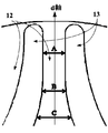
- FIG. 1 is a schematic diagram of an air gap in an electromagnetic steel sheet constituting a rotor in the prior art.
- FIG. 2 is an enlarged view of a dotted frame P shown in FIG. 1 of the prior art.
- the direction in which the magnetic flux easily flows is defined as the direct axis (d-axis)
- the direction in which the magnetic flux does not easily flow is defined as the horizontal axis (q-axis).
- each air gap 13 of the electromagnetic steel sheet 12 constituting the rotor 11 has the same width in the radial direction of the motor, or the width is radial from the inside in the radial direction. It decreases to the outside in order (not shown).
- the present inventor has found that such a configuration increases the torque ripple of the motor and suppresses the reluctance torque of the motor.
- the width of the electromagnetic steel sheet 12 between the two air gaps 13 at the innermost radial direction decreases in order from the radially inner side to the radially outer side, that is, A
- ⁇ B ⁇ C the magnetic resistance in the d-axis direction of the rotor 11 is maximized at a location close to the stator 14. This reduces the reluctance torque because the magnetic resistance difference between the magnetic resistance in this region and the flux barrier is reduced.
- an embodiment of the present invention provides a rotor, a motor including the rotor, and a power unit including the motor in order to increase reluctance torque and reduce torque ripple.
- a rotor is provided, and the rotor is located on the outer periphery of a rotating shaft of a motor, rotates with the rotating shaft, and is composed of electromagnetic steel plates stacked in an axial direction.
- a through hole group that penetrates the electromagnetic steel sheet in the axial direction, the through hole group has a plurality of through holes, and the plurality of through holes have a virtual line extending in the radial direction as a center line, and the center line
- the plurality of through-holes are arranged in a radial direction, and of these plurality of through-holes, the innermost radial through-hole is located radially inward.
- the radius of curvature of the arcuate surface is the smallest, and the radius of curvature of the arcuate surface located on the radially outer side of the plurality of through holes is the largest in the radially outer through hole.
- the curvature radius of the arc-shaped surface of the through hole other than the through hole at the innermost radial direction and the through hole at the outermost radial direction, and the innermost radial direction of the through hole is the same as the radius of curvature of the arcuate surface located on the radially inner side of the through hole on the radially outermost side.
- the electrical steel sheets located between two adjacent through holes have the same radial width.
- the radial width of the plurality of through holes is the radial width of the through hole on the innermost radial side> the radial width of the through hole on the outermost radial direction> It has the relationship of the width in the radial direction of the through hole other than the through hole at the innermost radial direction and the through hole at the outermost radial direction.
- the electrical steel sheet when viewed from the axial direction, has a plurality of through-hole groups that face the rotating shaft and are arranged in the circumferential direction.
- the two through holes located at the innermost radial direction of the two through hole groups adjacent in the circumferential direction extend in the direction in which the tips are separated from each other.
- the electrical steel sheet has four groups of through holes.
- the electrical steel sheet further includes a slit positioned between the plurality of through holes, and the slit has a width in the radial direction that is greater than a width in the radial direction of the plurality of through holes. Is also small.
- each slit has the same width in the radial direction.
- the electrical steel sheet has a slit on the radially outer side of the most radially outer through hole, and the slit has a radial width in the radial direction of the plurality of through holes. Smaller than.
- a rotating shaft extending along the central axis, the rotor according to any one of the first to tenth surfaces rotating about the rotating shaft,
- a motor having a stator and a stator opposed in the radial direction.
- the stator has a plurality of teeth portions extending radially inward, and the slots located between the teeth portions are arranged in the radial direction with the tips of the through holes of the through hole group. Opposite to.
- a power unit having the motor described above is provided.
- the beneficial effect of the embodiment of the present invention is that the reluctance torque can be improved and the torque ripple can be reduced by adjusting the shape (width or curvature) of the through hole in the electromagnetic steel sheet.
- FIG. 1 is a schematic diagram of an air gap in an electromagnetic steel sheet that constitutes a rotor in the prior art.
- FIG. 2 is an enlarged view of the dotted frame P in FIG.
- FIG. 3 is a plan view of the rotor according to the first embodiment of the present invention.
- FIG. 4 is an enlarged view of the dotted frame M in FIG. FIG.
- FIG. 5 is a plan view of a part of the rotor according to the first embodiment of the present invention.
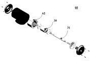
- FIG. 6 is an exploded schematic view of the motor of Example 2 of the present invention.
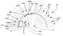
- FIG. 7 is a plan view of a part of the stator of the motor according to the second embodiment of the present invention.
- FIG. 3 is a plan view of the rotor according to the first embodiment of the present invention.
- the rotor is made of an electromagnetic steel sheet laminated in the axial direction.
- FIG. 3 is a view of one electromagnetic steel sheet as viewed from the axial direction.
- the rotor 30 is positioned on the outer periphery of the rotating shaft 31 of a motor (not shown) and rotates together with the rotating shaft 31.
- the rotor 30 is composed of electromagnetic steel plates 32 stacked in the axial direction.
- the electromagnetic steel plate 32 has a through hole group 33 that penetrates the electromagnetic steel plate 32 in the axial direction.
- Each through-hole group 33 has a plurality of through-holes 34.
- Each of the plurality of through holes 34 has an imaginary line extending in the radial direction as a center line (for example, the q axis shown in FIG. 3), has an arc shape extending to both sides of the q axis and radially outward, and the plurality of through holes 34 are arranged in the radial direction.
- the radius of curvature r 1 of the arc-shaped surface 3411 located on the radially inner side of the through hole 341 that is radially innermost among the plurality of through holes 34 is the smallest, and the diameter of the plurality of through holes 34 is the smallest.
- the radius of curvature r 0 of the arc-shaped surface 3421 located on the radially outer side of the through hole 342 on the outer side in the direction is the largest.
- the radius of curvature r 1 of the arcuate surface 3411 located radially inward of the through hole 341 on the innermost radial direction among all the arc surfaces of the plurality of through holes arranged in the radial direction is the smallest
- the radius of curvature r 0 of the arc-shaped surface 3421 located on the radially outer side of the through hole 342 on the outermost radial direction is the largest.
- the width of the through hole on the innermost radial direction and the outermost radial direction can be increased, and the difference in magnetic resistance between the electromagnetic steel sheets constituting the rotor can be increased, thereby reducing the reluctance torque. Can be increased.
- the present embodiment is not limited thereto, and only the width of the through hole on the most radially inner side may be expanded, or You may enlarge only the width
- the radius of curvature r 1 and the most radial direction of the arc-shaped surface 3411 located radially inward of the through hole 341 on the innermost radial direction The radius of curvature r 0 of the arc-shaped surface 3421 located on the radially outer side of the outer through-hole 342 is different, and the radius of curvature of the other arc-shaped surfaces is all the same.
- the through hole 341 and the through hole 343 are two adjacent through holes, and the through hole 343 and the through hole 342 are also two adjacent through holes.
- the electromagnetic steel sheet between the adjacent through holes 342 and the through holes 343 has a radial width d1
- the electromagnetic steel sheet between the adjacent through holes 341 and the through holes 343 has a radial width d2.
- the width in the radial direction of the plurality of through holes is the width D1 in the radial direction of the through hole 341 on the innermost radial direction> the width D2 in the radial direction of the through hole 342 on the outermost radial direction>
- a relationship of a radial width D3 of the through hole located between the innermost through hole 341 and the outermost through hole 342 may be further provided.
- the number of through holes 343 positioned between the innermost through hole 341 and the outermost through hole 342 in the radial direction is one. Therefore, the width D1 in the radial direction of the through hole 341> the width D2 in the radial direction of the through hole 342> the width D3 in the radial direction of the through hole 343.
- Such a structure can reduce torque ripple even when the rotor diameter is small and the number of through holes cannot be increased.
- the electromagnetic steel sheet 32 when viewed from the axial direction, has a plurality of through-hole groups 33 (as shown in the dotted frame N in FIG. 3, for convenience, in FIG.
- the dotted line frame N shows only one through hole group, and the other through hole groups are similar to the part surrounded by the dotted line frame N).
- the plurality of through-hole groups 33 are opposed to the rotation shaft 31 in the radial direction and are arranged in the circumferential direction.
- the present embodiment is not limited to this, and the number of through-hole groups may be other numbers. Normally, the number of through-hole groups is determined by the number of poles of the magnetoresistive motor.
- each through hole group has three through holes.
- this embodiment is not limited to this, and the number of through holes in each through hole group is another number. May be.
- the magnetic flux in the d-axis direction may be increased in order to further increase the reluctance torque.
- 4 is an enlarged view of a dotted frame M shown in FIG. 3 of Embodiment 1 of the present invention.
- FIG. 4 shows two through-holes 341 and 341 ′ positioned at the innermost radial direction among the two through-hole groups 33 1 and 332 adjacent in the circumferential direction.
- the tips of the two through holes 341 and 341 ' extend in a direction away from each other in the circumferential direction. That is, of the two through hole groups adjacent in the circumferential direction, the distal ends of the two through holes that are located on the innermost radial direction extend in the direction away from each other in the circumferential direction as they go radially outward.
- the tips 341a and 341'a of the two through holes 341 and 341 ' are inclined at a predetermined angle in directions indicated by arrows X and Y in FIG.
- the widths between the two through holes 341 and 341 ′ are C, B, and A from the radially inner side to the radially outer side, respectively.
- B ⁇ A ⁇ C can be established. That is, according to the present embodiment, the width A of the tips 341a and 341'a of the two through holes 341 and 341 'is radially outer than the width B where the width of the two through holes 341 and 341' is the narrowest.
- the reluctance is increased by increasing the magnetic resistance difference between this region (the region of the dotted frame M shown in FIG. 3) and the through hole. Increase torque further.
- FIG. 5 is a plan view of a part of the rotor according to the first embodiment of the present invention. Among them, FIG. 5 shows only the situation of one through hole group of the electromagnetic steel sheet constituting the rotor, and the embodiment of the other through hole group may be similar to the through hole group.
- the electromagnetic steel sheet 32 may further include a slit 35 positioned between the plurality of through holes 34, and the slit 35 has a radial width that is greater than a radial width of the plurality of through holes 34. Is also small.
- the slit 35 is a through hole that penetrates the electromagnetic steel sheet 32 in the axial direction.
- the slits 35 may be provided between the through holes 34, and the slits 36 may be provided on the radially outer side of the through holes 342 on the outermost radial direction.
- the slit 36 is a through hole that penetrates the electromagnetic steel sheet 32 in the axial direction.
- increasing the number of slits in each through-hole group corresponds to increasing the number of through-holes in each through-hole group, so that torque ripple can be further reduced.
- the number of slits 35 and 36 is three, but the present embodiment is not limited to this, and the number of slits 35 and 36 is another number. There may be.
- each slit 35 has the same width in the radial direction, but each slit 35 and slit 36 may have the same width in the radial direction. Thereby, torque ripple can be further reduced and reluctance torque can be increased by reducing the difference in magnetic flux passing through the electromagnetic steel sheet.
- the structure of the rotor of the present invention makes it possible to increase the magnetic resistance difference between the electromagnetic steel sheets constituting the rotor, thereby increasing the reluctance torque and reducing the torque ripple.
- Example 2 The embodiment of the present invention further provides a motor, and FIG. 6 is an exploded schematic view of the motor of Embodiment 2 of the present invention.
- the motor 60 includes a rotating shaft 31 extending along the central axis, the rotor 30 based on the rotating shaft 31 that rotates around the rotating shaft 31, and the rotor 30 facing the rotor 30 in the radial direction. And a stator 62.
- FIG. 7 is a plan view of a part of the motor according to the second embodiment of the present invention (shown in FIG. 7 is a cross-sectional sectional view of the motor cut along the motor axial direction).
- the stator 62 has a plurality of tooth portions 622 extending radially inward.
- the plurality of slots 621 located between the circumferential directions of the adjacent tooth portions 622 are opposed to the tips of the through holes 34 of the through hole group 33 in the radial direction.
- the two tips 341a and 341b of the innermost through-hole 341 are radially opposed to the slots 621 1 and 621 1 ′ , respectively, and the outermost through-hole is penetrated.
- the two tips 342a and 342b of the hole 342 are diametrically opposed to the slots 621 2 and 621 2 ' , respectively, and the two tips 343a and 343b of the through-hole 343 are diametrically aligned with the slots 621 3 and 621 3' , respectively. opposite. Thereby, torque ripple can be further reduced.
- the other components of the motor 60 are the same as those of the conventional technology, and the description thereof is omitted here.
- the structure of the rotor of the motor of the present invention can increase the magnetic resistance difference between the electrical steel sheets constituting the rotor, thereby increasing the reluctance torque and reducing the torque ripple.
- Example 3 The embodiment of the present invention provides a power unit, and the power unit has the motor described in Example 2.
- the main structure of the motor has already been described in detail. Since the contents are included here, they are omitted here.
- the power device may be any device to which a motor is attached, and the motor may be applied to power transmission of a bulldozer or a power shovel as a power device.
- the reluctance torque of the motor is increased and the torque ripple is reduced, so that a large torque can be easily output and the vibration can be reduced.
Landscapes
- Engineering & Computer Science (AREA)
- Power Engineering (AREA)
- Iron Core Of Rotating Electric Machines (AREA)
- Synchronous Machinery (AREA)
Abstract
本発明の実施例は、ロータ、当該ロータを含むモータ及び当該モータを含む動力装置を提供しており、当該ロータはモータの回転軸の外周に位置し、回転軸とともに回転し、軸方向に積層された電磁鋼板からなり、電磁鋼板は、当該電磁鋼板を軸方向に貫通する貫通孔群を有し、貫通孔群は複数の貫通孔を有し、複数の貫通孔は径方向に延びる仮想線を中心線とし、当該中心線の両側及び径方向外側へ延びる円弧状をなし、且つ、当該複数の貫通孔は径方向に配列され、そのうち、複数の貫通孔のうち最も径方向内側の貫通孔における、径方向内側に位置する円弧形の面の曲率半径が最も小さく、且つ/或いは複数の貫通孔のうち最も径方向外側の貫通孔における、径方向外側に位置する円弧形の面の曲率半径が最も大きい。
Description
本発明は、モータの分野に関し、特にロータ、当該ロータを含むモータ及び当該モータを含む動力装置に関する。
シンクロナスリラクタンスモータのロータにおいて、ロータを構成する電磁鋼板は複数の貫通孔を有し、これらの貫通孔によりフラックスバリアと名づけられるエアギャップが形成され、これらのエアギャップにより磁気抵抗の差異が生じ、モータに電流が通じるときに、磁気抵抗の差異によりリラクタンストルクが生じる。
図1は従来の技術においてロータを構成する電磁鋼板でのエアギャップの模式図である。図2は、従来の技術の図1に示されている点線枠Pの拡大図である。そのうち、ロータで磁束の流れやすい方向を直軸(d軸)に定義し、磁束の流れにくい方向を横軸(q軸)に定義する。図1に示すように、従来のシンクロナスリラクタンスモータ10において、ロータ11を構成する電磁鋼板12の各エアギャップ13はモータの径方向における幅が同一であり、又は幅が径方向内側から径方向外側へ順に減少する(未図示)。本発明者は、このような構成がモータのトルクリップルが増大してしまい、モータのリラクタンストルクが抑制されることを発見した。
なお、図1と図2に示すように、d軸方向において、最も径方向内側の2つのエアギャップ13間の電磁鋼板12の幅は径方向内側から径方向外側へ順に減少し、即ち、A<B<Cとなることによって、ロータ11のd軸方向における磁気抵抗はステータ14に近い箇所で最も大きくなってしまう。これにより、この領域の磁気抵抗とフラックスバリアとの間の磁気抵抗差異が縮めるため、リラクタンストルクが低下してしまう。
上記の背景技術に対する紹介はただ本願の技術内容を明瞭かつ完全に説明することを便利にするとともに、当業者に便利に理解させるために述べられたものに過ぎないということに注意すべきである。これらの技術内容が本願の背景技術という部分で述べられたため、上記の技術内容を当業者にとって公知なものに見なすことができない。
上記の課題を解決するために、本発明の実施例は、リラクタンストルクを高め、トルクリップルを低減させるために、ロータ、当該ロータを含むモータ及び当該モータを含む動力装置を提供する。
本発明の一実施例によれば、ロータが提供され、当該ロータはモータの回転軸の外周に位置し、当該回転軸とともに回転し、軸方向に積層された電磁鋼板からなり、当該電磁鋼板は、当該電磁鋼板を軸方向に貫通する貫通孔群を有し、当該貫通孔群は複数の貫通孔を有し、当該複数の貫通孔は径方向に延びる仮想線を中心線とし、当該中心線の両側及び径方向外側へ延びる円弧状をなし、且つ、当該複数の貫通孔は径方向に配列され、そのうち、当該複数の貫通孔のうち最も径方向内側の貫通孔における、径方向内側に位置する円弧形の面の曲率半径が最も小さく、当該複数の貫通孔のうち最も径方向外側の貫通孔における、径方向外側に位置する円弧形の面の曲率半径が最も大きい。
本発明の一実施例によれば、そのうち、最も径方向内側の当該貫通孔及び最も径方向外側の当該貫通孔以外の貫通孔の円弧形の面の曲率半径と、最も径方向内側の当該貫通孔の径方向外側に位置する円弧形の面の曲率半径と、最も径方向外側の当該貫通孔の径方向内側に位置する円弧形の面の曲率半径とは同一である。
本発明の一実施例によれば、隣接する2つの貫通孔の間に位置する当該電磁鋼板は径方向における幅が同一である。
本発明の一実施例によれば、当該複数の貫通孔の径方向における幅は、最も径方向内側の当該貫通孔の径方向における幅>最も径方向外側の当該貫通孔の径方向における幅>最も径方向内側の当該貫通孔及び最も径方向外側の当該貫通孔以外の貫通孔の径方向における幅、という関係を有している。
本発明の一実施例によれば、軸方向から見ると、当該電磁鋼板は、当該回転軸に対して対向するとともに、周方向に配列される複数の当該貫通孔群を有する。
本発明の一実施例によれば、周方向に隣接する2つの当該貫通孔群の最も径方向内側に位置する2つの当該貫通孔は先端が互いに離間する方向へ延びる。
本発明の一実施例によれば、当該電磁鋼板は、4つの当該貫通孔群を有する。
本発明の一実施例によれば、当該電磁鋼板は、当該複数の貫通孔の間に位置するスリットをさらに有し、当該スリットは径方向における幅が当該複数の貫通孔の径方向における幅よりも小さい。
本発明の一実施例によれば、当該スリットは複数あり、且つ、各当該スリットは径方向における幅が全て同一である。
本発明の一実施例によれば、当該電磁鋼板は、最も径方向外側の貫通孔の径方向外側にスリットを有し、当該スリットは径方向における幅が当該複数の貫通孔の径方向における幅よりも小さい。
本発明の一実施例によれば、中心軸に沿って延びる回転軸と、当該回転軸を中心に回転する、上記第1の面から第10の面のいずれか1つに記載のロータと、当該ロータと径方向に対向するステータと、を有するモータが提供されている。
本発明の一実施例によれば、当該ステータは、径方向内側へ延びる複数のティース部を有し、当該ティース部間に位置するスロットは当該貫通孔群の各当該貫通孔の先端と径方向に対向する。
本発明の一実施例によれば、上記に記載のモータを有する動力装置が提供されている。
本発明の実施例による有益な効果は、電磁鋼板における貫通孔の形状(幅又は曲率)を調整することにより、リラクタンストルクを向上させ、トルクリップルを低減させることができることにある。
後述の説明と図を参照して、本発明の特定の実施形態を詳しく開示し、本発明の原理を採用可能な形態を明らかにした。本発明の実施形態は範囲でそれによって制限されるものではないということを理解すべきである。記載された特許請求の範囲の思想と項目を逸脱しない範囲で、本発明の実施形態は複数の変更、補正と同等を含む。
含まれている図は本発明実施例に対してさらに理解するために提供されるものであり、明細書の一部を構成し、本発明の実施形態を例示するとともに、文字記載と一緒に本発明の原理を説明する。下記の図はただ本発明の若干の実施例に過ぎず、当業者にとって、創造的な労働を要しない前提において、これらの図に基づいて他の図を得ることもできる。
図1は、従来の技術においてロータを構成する電磁鋼板でのエアギャップの模式図である。
図2は、図1における点線枠Pの拡大図である。
図3は、本発明の実施例1のロータの平面図である。
図4は、図3における点線枠Mの拡大図である。
図5は、本発明の実施例1のロータの一部の平面図である。
図6は、本発明の実施例2のモータの分解模式図である。
図7は、本発明の実施例2のモータのステータの一部の平面図である。
図を参照して、下記の説明によって、本発明の上記及び他の特徴を明らかにする。明細書と図において、具体的に本発明の特定した実施形態を開示し、本発明の原則を採用可能な一部の実施形態を示している。本発明は記載されている実施形態に限らないどころか、本発明は記載されている特許請求の範囲内のすべての補正、変形及び同等物を含む。
以下、図を参照しながら本発明の実施例の好ましい実施の形態を説明する。
本発明の実施例の以下の説明で、説明しやすいために、軸に沿って延びる方向と平行な方向を「軸方向」と称され、軸を中心とした半径方向を「径方向」と称され、軸を中心とした円周方向を「周方向」と称されるが、いずれも説明の便宜のために過ぎず、モータの使用及び製造時の向けを限定するものではない。
本発明の実施例の以下の説明で、説明しやすいために、軸に沿って延びる方向と平行な方向を「軸方向」と称され、軸を中心とした半径方向を「径方向」と称され、軸を中心とした円周方向を「周方向」と称されるが、いずれも説明の便宜のために過ぎず、モータの使用及び製造時の向けを限定するものではない。
実施例1
本発明の実施例は、ロータを提供する。図3は、本発明の実施例1のロータの平面図である。ロータが軸方向に積層された電磁鋼板からなる。図3は、1枚の電磁鋼板を軸方向から見た面である。
本発明の実施例は、ロータを提供する。図3は、本発明の実施例1のロータの平面図である。ロータが軸方向に積層された電磁鋼板からなる。図3は、1枚の電磁鋼板を軸方向から見た面である。
図3に示すように、ロータ30がモータ(未図示)の回転軸31の外周に位置し、回転軸31とともに回転する。ロータ30は軸方向に積層された電磁鋼板32からなる。電磁鋼板32は、電磁鋼板32を軸方向に貫通する貫通孔群33を有する。貫通孔群33はそれぞれ複数の貫通孔34を有する。複数の貫通孔34のそれぞれは径方向に延びる仮想線を中心線とし(例えば、図3に示すq軸)、q軸の両側及び径方向外側へ延びる円弧状であり、且つ、複数の貫通孔34は径方向に配列される。
本実施において、複数の貫通孔34のうち最も径方向内側の貫通孔341の径方向内側に位置する円弧形の面3411の曲率半径r1が最も小さく、複数の貫通孔34のうち最も径方向外側の貫通孔342の径方向外側に位置する円弧形の面3421の曲率半径r0が最も大きい。即ち、径方向に配列される複数の貫通孔の全ての円弧面のうち、最も径方向内側の貫通孔341の径方向内側に位置する円弧形の面3411の曲率半径r1が最も小さく、且つ、最も径方向外側の貫通孔342の径方向外側に位置する円弧形の面3421の曲率半径r0が最も大きい。
このような構造により、最も径方向内側と最も径方向外側の貫通孔の幅を拡大させることができ、ロータを構成する電磁鋼板間の磁気抵抗の差異を拡大させることができることにより、リラクタンストルクを増大させることができる。
なお、最も径方向内側と最も径方向外側の貫通孔の幅を同時に拡大させるが、本実施例はそれに限らず、最も径方向内側の貫通孔の幅のみを拡大させてもよく、又は最も径方向外側の貫通孔の幅のみを拡大させてもよい。即ち、最も径方向内側の貫通孔341の径方向内側に位置する円弧形の面3411の曲率半径r1のみを最も小さく設置してもよく、又は、最も径方向外側の貫通孔342の径方向外側に位置する円弧形の面3421の曲率半径r0のみを最も大きく設置してもよい。これにより、同様にリラクタンストルクを増大させることができる。
本実施において、図3に示すように、複数の貫通孔34のうち、径方向において、最も径方向内側の貫通孔341及び最も径方向外側の貫通孔342の間に位置する貫通孔343の円弧形の面の曲率半径と、最も径方向内側の貫通孔341の径方向外側に位置する円弧形の面3412の曲率半径と、最も径方向外側の貫通孔342の径方向内側に位置する円弧形の面3422の曲率半径は同一である。即ち、径方向に配列される複数の貫通孔の全ての円弧面のうち、最も径方向内側の貫通孔341の径方向内側に位置する円弧形の面3411の曲率半径r1及び最も径方向外側の貫通孔342の径方向外側に位置する円弧形の面3421の曲率半径r0が異なるほか、他の円弧形の面の曲率半径が全て同一である。このような構造により、さらに磁気抵抗差異を拡大させ、リラクタンストルクを増大させることができる。
本実施例において、図3に示すように、貫通孔341と貫通孔343は隣接する2つの貫通孔であり、貫通孔343と貫通孔342も隣接する2つの貫通孔である。隣接する貫通孔342と貫通孔343との間の電磁鋼板は径方向における幅がd1であり、隣接する貫通孔341と貫通孔343との間の電磁鋼板は径方向における幅がd2とすると、d1=d2の関係である。即ち、隣接する2つの貫通孔の間に位置する電磁鋼板は径方向における幅が同一である。
このような構造により、電磁鋼板を通過する磁束の差異を低減させることにより、さらにトルクリップルを低減させ、リラクタンストルクを増大させることができる。
本実施例において、複数の貫通孔の径方向における幅は、最も径方向内側の貫通孔341の径方向における幅D1>最も径方向外側の貫通孔342の径方向における幅D2>径方向において、最も径方向内側の貫通孔341及び最も径方向外側の貫通孔342の間に位置する貫通孔の径方向における幅D3、という関係をさらに有してもよい。
本実施例において、図3に示すように、径方向において、最も径方向内側の貫通孔341及び最も径方向外側の貫通孔342の間に位置する貫通孔343の数は1つである。そのため、貫通孔341の径方向における幅D1>貫通孔342の径方向における幅D2>貫通孔343の径方向における幅D3となる。
このような構造では、ロータの径が小さく、貫通孔の数を増やせない場合においても、トルクリップルを低減させることができる。
本実施例において、図3に示すように、軸方向から見ると、電磁鋼板32は、複数の貫通孔群33を有する(図3の点線枠Nに示すように、便宜のため、図3における点線枠Nは1つの貫通孔群のみを示し、他の貫通孔群は点線枠Nに囲まれた部位と類似する)。複数の貫通孔群33は、回転軸31に対して、径方向に対向し、かつ、周方向に配列する。
本実施例の1つの実施の形態において、図3に示すように、電磁鋼板32は、4つの貫通孔群33iを有してもよい(i=1~4)。しかし、本実施例はそれに限らず、貫通孔群の数は他の数であってもよく、通常、貫通孔群の数は磁気抵抗モータの極数によって決定されるものである。
また、本実施例において、図3に示すように、各貫通孔群は3つの貫通孔を有するが、本実施例もそれに限らず、各貫通孔群における貫通孔の数は他の数であってもよい。
本実施例において、リラクタンストルクをさらに増大させるために、d軸方向の磁束を増大させてもよい。図4は、本発明実施例1の図3に示す点線枠Mの拡大図である。
図4は、周方向に隣接する2つの貫通孔群331及び332のうち最も径方向内側に位置する2つの貫通孔341及び341’を示す。2つの貫通孔341及び341’のそれぞれの先端は互いに周方向に離れる方向へ延びる。即ち、周方向に隣接する2つの前記貫通孔群のうち最も径方向内側に位置する2つの前記貫通孔の先端は、互いに径方向外側に向かうにつれて、互いが周方向に離れる方向へ延びる。2つの貫通孔341及び341’の先端341a及び341’aは、それぞれ図4の矢印X及びYに示す方向へ所定の角度で傾く。d軸方向において、2つの貫通孔341及び341’間の幅は、径方向内側から径方向外側へそれぞれC、B、Aとする。上記のような構造により、B<A<Cにすることができる。すなわち、本実施例によれば、2つの貫通孔341及び341’の先端341a及び341’aの幅Aは、2つの貫通孔341及び341’の幅が最も狭くなる幅Bよりも径方向外側に位置する。このような構造により、d軸方向の磁束を増大させることにより、この領域(図3に示す点線枠Mの領域)の磁気抵抗と貫通孔との間の磁気抵抗差異を増大させることにより、リラクタンストルクをさらに増大させる。
本実施例において、トルクリップルをさらに低減させるために、各貫通孔群における貫通孔の数を増加してもよい。図5は、本発明の実施例1のロータの一部の平面図である。そのうち、図5は、ロータを構成する電磁鋼板の1つの貫通孔群の状況のみを示し、他の貫通孔群の実施の形態は、当該貫通孔群と類似してもよい。
図5に示すように、電磁鋼板32は複数の貫通孔34の間に位置するスリット35をさらに有してもよく、スリット35は径方向における幅が複数の貫通孔34の径方向における幅よりも小さい。スリット35は、電磁鋼板32を軸方向に貫通する貫通孔である。
本実施例において、図5に示すように、各貫通孔34の間にスリット35を有するほか、最も径方向外側の貫通孔342の径方向外側にもスリット36を有してもよい。スリット36は、電磁鋼板32を軸方向に貫通する貫通孔である。
このような構造により、各貫通孔群にスリットを増加することが各貫通孔群における貫通孔の数を増加することに相当するため、トルクリップルをさらに低減させることができる。
本実施例の1つの実施の形態において、図5に示すように、スリット35と36の数は3つであるが、本実施例はそれに限らず、スリット35と36の数は他の数であってもよい。
本実施例において、各スリット35は径方向における幅が同一であるが、各スリット35とスリット36は径方向における幅が同一であってもよい。これにより、電磁鋼板を通過する磁束の差異を低減させることにより、さらにトルクリップルを低減させ、リラクタンストルクを増大させることができる。
本実施例において、各スリット35は径方向における幅が同一であるが、各スリット35とスリット36は径方向における幅が同一であってもよい。これにより、電磁鋼板を通過する磁束の差異を低減させることにより、さらにトルクリップルを低減させ、リラクタンストルクを増大させることができる。
本発明のロータの構造により、ロータを構成する電磁鋼板間の磁気抵抗差異を拡大させることができ、これにより、リラクタンストルクを増大させ、トルクリップルを低減させることができる。
実施例2
本発明の実施例はモータをさらに提供しており、図6は、本発明の実施例2のモータの分解模式図である。
本発明の実施例はモータをさらに提供しており、図6は、本発明の実施例2のモータの分解模式図である。
図6に示すように、モータ60は、中心軸に沿って延びる回転軸31と、回転軸31を中心に回転する、上述した実施例1に基づいたロータ30と、ロータ30と径方向に対向するステータ62と、を有してもよい。
本実施例において、トルクリップルをさらに低減させるには、モータのステータのスロットとロータを構成する電磁鋼板の貫通孔との間に一定の対応関係を有している。
図7は、本発明の実施例2のモータの一部の平面図である(図7に示すのは、モータの軸方向に沿ってモータを切断したモータの横断面断面図である)。
本実施例において、図6と図7に示すように、ステータ62は、径方向内側へ延びる複数のティース部622を有する。隣り合うティース部622の周方向の間に位置する複数のスロット621は、貫通孔群33の各貫通孔34の先端に対して径方向に対向する。具体的には、図6に示すように、最も径方向内側の貫通孔341の2つの先端341aと341bは、それぞれスロット6211と6211’と径方向に対向し、最も径方向外側の貫通孔342の2つの先端342aと342bは、それぞれスロット6212と6212’と径方向に対向し、貫通孔343の2つの先端343aと343bは、それぞれスロット6213と6213’と径方向に対向する。これにより、トルクリップルをさらに低減させることができる。
本実施例において、モータ60の他の構成部材は従来の技術と同様であり、ここでその説明を省略する。
本発明のモータのロータの構造により、ロータを構成する電磁鋼板間の磁気抵抗差異を拡大させることができ、これにより、リラクタンストルクを増大させ、トルクリップルを低減させる。
実施例3
本発明の実施例は動力装置を提供しており、当該動力装置は、実施例2に記載のモータを有しており、実施例2にて、既に当該モータの主な構造について詳細に説明したため、その内容がここに含まれるため、ここで省略する。
本発明の実施例は動力装置を提供しており、当該動力装置は、実施例2に記載のモータを有しており、実施例2にて、既に当該モータの主な構造について詳細に説明したため、その内容がここに含まれるため、ここで省略する。
本実施例において、上記のように、当該動力装置は、モータの装着される何らの機器でもよく、当該モータは、動力装置とするブルドーザまたはパワーショベルの動力伝動に適用されてもよい。
本発明の動力装置は、モータのリラクタンストルクが増大され、トルクリップルが低減されるにより、大きなトルクを出力しやすく、かつ、振動を低減することができる。
上記、具体的な実施形態で本発明を記載したが、当業者にとって、これらの記載は例示的なものであって、本発明実施例の特許請求する範囲に対する制限ではないということが分かっているはずである。当業者は、本発明の思想と原理に基づいて、本発明に対して各種の変形と補正をしてもよく、これらの変形と補正も本発明の範囲内にある。
60 モータ、31 回転軸、31 電磁鋼板、30 ロータ、33 貫通孔群、34 複数の貫通孔
Claims (13)
- モータの回転軸の外周に位置し、前記回転軸とともに回転し、軸方向に積層された電磁鋼板からなるロータであって、前記電磁鋼板は、前記電磁鋼板を軸方向に貫通する貫通孔群を有し、前記貫通孔群は複数の貫通孔を有し、前記複数の貫通孔は径方向に延びる仮想線を中心線とし、前記中心線の両側及び径方向外側へ延びる円弧状であり、且つ、前記複数の貫通孔は径方向に配列されるロータにおいて、
前記複数の貫通孔のうち最も径方向内側の貫通孔における、径方向内側に位置する円弧形の面の曲率半径が最も小さく、
前記複数の貫通孔のうち最も径方向外側の貫通孔における、径方向外側に位置する円弧形の面の曲率半径が最も大きいことを特徴とするロータ。 - 請求項1に記載のロータにおいて、
径方向において、前記最も径方向内側の貫通孔と前記最も径方向外側の前記貫通孔との間に位置する貫通孔の円弧形の面の曲率半径と、
前記最も径方向内側の貫通孔における径方向外側に位置する円弧形の面の曲率半径と、
前記最も径方向外側の前記貫通孔における径方向内側に位置する円弧形の面の曲率半径とは同一であることを特徴とする。 - 請求項2に記載のロータにおいて、
前記貫通孔群のうち隣接する2つの貫通孔の間の径方向の幅は同一であることを特徴とする。 - 請求項1に記載のロータにおいて、
前記複数の貫通孔の径方向における幅は、前記最も径方向内側の貫通孔の径方向における幅>前記最も径方向外側の貫通孔の径方向における幅>径方向において、前記最も径方向内側の貫通孔と前記最も径方向外側の貫通孔との間に位置する貫通孔の径方向における幅、という関係を有していることを特徴とする。 - 請求項1に記載のロータにおいて、
前記電磁鋼板は、複数の貫通孔群を有し、前記複数の貫通孔群は、前記回転軸に対して、径方向に対向し、かつ、周方向に配列することを特徴とする。 - 請求項5に記載のロータにおいて、
周方向に隣接する2つの前記貫通孔群のうち最も径方向内側に位置する2つの前記貫通孔の先端は、互いに径方向外側に向かうにつれて、周方向に離れる方向へ延びることを特徴とする。 - 請求項5に記載のロータにおいて、
前記電磁鋼板は、4つの前記貫通孔群を有することを特徴とする。 - 請求項4に記載のロータにおいて、
前記電磁鋼板は、前記複数の貫通孔の間に位置し、軸方向に貫通するスリットをさらに有し、前記スリットは径方向における幅が前記複数の貫通孔の径方向における幅よりも小さいことを特徴とする。 - 請求項8に記載のロータにおいて、
前記スリットは複数あり、且つ、各前記スリットは径方向における幅が全て同一であることを特徴とする。 - 請求項4に記載のロータにおいて、
前記電磁鋼板は、前記最も径方向外側の貫通孔よりも径方向外側に位置するスリットを有し、前記スリットは径方向における幅が前記複数の貫通孔の径方向における幅よりも小さいことを特徴とする。 - 中心軸に沿って延びる回転軸と、
前記回転軸を中心に回転する、請求項1~10のいずれか1つに記載のロータと、
前記ロータと径方向に対向するステータと、を有することを特徴とするモータ。 - 請求項11に記載のモータにおいて、
前記ステータは、径方向内側へ延びる複数のティース部を有し、
隣り合う前記ティース部の周方向の間に位置する複数のスロットは、前記貫通孔群の各前記貫通孔の先端に対して径方向に対向することを特徴とする。 - 請求項11または12に記載のモータを有することを特徴とする動力装置。
Priority Applications (2)
| Application Number | Priority Date | Filing Date | Title |
|---|---|---|---|
| US16/477,222 US11018534B2 (en) | 2017-02-28 | 2018-02-19 | Rotor, motor including rotor, and power unit including motor |
| JP2019502880A JPWO2018159339A1 (ja) | 2017-02-28 | 2018-02-19 | ロータ、当該ロータを含むモータ及び当該モータを含む動力装置 |
Applications Claiming Priority (2)
| Application Number | Priority Date | Filing Date | Title |
|---|---|---|---|
| CN201710112720.0 | 2017-02-28 | ||
| CN201710112720.0A CN108512327B (zh) | 2017-02-28 | 2017-02-28 | 转子、包含该转子的马达、以及包含该马达的动力装置 |
Publications (1)
| Publication Number | Publication Date |
|---|---|
| WO2018159339A1 true WO2018159339A1 (ja) | 2018-09-07 |
Family
ID=63370064
Family Applications (1)
| Application Number | Title | Priority Date | Filing Date |
|---|---|---|---|
| PCT/JP2018/005618 Ceased WO2018159339A1 (ja) | 2017-02-28 | 2018-02-19 | ロータ、当該ロータを含むモータ及び当該モータを含む動力装置 |
Country Status (4)
| Country | Link |
|---|---|
| US (1) | US11018534B2 (ja) |
| JP (1) | JPWO2018159339A1 (ja) |
| CN (1) | CN108512327B (ja) |
| WO (1) | WO2018159339A1 (ja) |
Cited By (1)
| Publication number | Priority date | Publication date | Assignee | Title |
|---|---|---|---|---|
| JP2023174445A (ja) * | 2022-05-26 | 2023-12-07 | 國立宜蘭大學 | モーターローターとその設計方法 |
Families Citing this family (5)
| Publication number | Priority date | Publication date | Assignee | Title |
|---|---|---|---|---|
| CN112152350B (zh) * | 2019-06-28 | 2023-08-15 | 日本电产株式会社 | 转子、马达以及驱动装置 |
| CN113675968B (zh) * | 2020-05-15 | 2023-10-31 | 日本电产株式会社 | 转子、马达和电气产品 |
| CN219181380U (zh) * | 2022-12-14 | 2023-06-13 | 日本电产株式会社 | 同步磁阻电机 |
| CN119010398A (zh) * | 2023-05-19 | 2024-11-22 | 尼得科运动控制技术(广东)有限公司 | 转子和马达 |
| TWI912947B (zh) * | 2024-09-26 | 2026-01-21 | 國立宜蘭大學 | 同步磁阻馬達及其設計方法 |
Citations (4)
| Publication number | Priority date | Publication date | Assignee | Title |
|---|---|---|---|---|
| JP2007129884A (ja) * | 2005-11-07 | 2007-05-24 | Toyota Industries Corp | リラクタンスモータのロータ |
| JP2008022672A (ja) * | 2006-07-14 | 2008-01-31 | Toshiba Corp | リラクタンスモータ |
| US20150372546A1 (en) * | 2014-06-23 | 2015-12-24 | Siemens Aktiengesellschaft | Mechanically stabilized rotor for a reluctance motor |
| JP2017017957A (ja) * | 2015-07-06 | 2017-01-19 | 株式会社ジェイテクト | シンクロナスリラクタンスモータ |
Family Cites Families (8)
| Publication number | Priority date | Publication date | Assignee | Title |
|---|---|---|---|---|
| JP4027591B2 (ja) * | 2000-12-21 | 2007-12-26 | 株式会社日立製作所 | 同期リラクタンスモータ |
| JP4367375B2 (ja) * | 2005-05-17 | 2009-11-18 | 株式会社デンソー | リラクタンスモータ用ロータコア及びその製造方法 |
| CN102761183B (zh) * | 2011-08-05 | 2013-06-19 | 珠海格力电器股份有限公司 | 电动机转子及具有其的电动机 |
| JP2013046434A (ja) * | 2011-08-22 | 2013-03-04 | Daikin Ind Ltd | 回転電気機械 |
| US8664822B2 (en) * | 2012-05-30 | 2014-03-04 | GM Global Technology Operations LLC | Bi-permanent magnets in synchronous machines |
| JP6366986B2 (ja) * | 2014-04-11 | 2018-08-01 | 株式会社東芝 | 同期リラクタンス型回転電機 |
| RU2634587C1 (ru) * | 2016-07-26 | 2017-11-01 | Общество с ограниченной ответственностью "ЭМАШ" | Синхронная реактивная машина |
| JP6709712B2 (ja) * | 2016-10-07 | 2020-06-17 | 東芝産業機器システム株式会社 | 同期リラクタンス型回転電機 |
-
2017
- 2017-02-28 CN CN201710112720.0A patent/CN108512327B/zh active Active
-
2018
- 2018-02-19 WO PCT/JP2018/005618 patent/WO2018159339A1/ja not_active Ceased
- 2018-02-19 US US16/477,222 patent/US11018534B2/en active Active
- 2018-02-19 JP JP2019502880A patent/JPWO2018159339A1/ja active Pending
Patent Citations (4)
| Publication number | Priority date | Publication date | Assignee | Title |
|---|---|---|---|---|
| JP2007129884A (ja) * | 2005-11-07 | 2007-05-24 | Toyota Industries Corp | リラクタンスモータのロータ |
| JP2008022672A (ja) * | 2006-07-14 | 2008-01-31 | Toshiba Corp | リラクタンスモータ |
| US20150372546A1 (en) * | 2014-06-23 | 2015-12-24 | Siemens Aktiengesellschaft | Mechanically stabilized rotor for a reluctance motor |
| JP2017017957A (ja) * | 2015-07-06 | 2017-01-19 | 株式会社ジェイテクト | シンクロナスリラクタンスモータ |
Cited By (3)
| Publication number | Priority date | Publication date | Assignee | Title |
|---|---|---|---|---|
| JP2023174445A (ja) * | 2022-05-26 | 2023-12-07 | 國立宜蘭大學 | モーターローターとその設計方法 |
| JP7437808B2 (ja) | 2022-05-26 | 2024-02-26 | 國立宜蘭大學 | モーターローターとその設計方法 |
| US12266975B2 (en) | 2022-05-26 | 2025-04-01 | National Ilan University | Rotor and design method thereof |
Also Published As
| Publication number | Publication date |
|---|---|
| US11018534B2 (en) | 2021-05-25 |
| US20190348874A1 (en) | 2019-11-14 |
| CN108512327B (zh) | 2020-05-22 |
| CN108512327A (zh) | 2018-09-07 |
| JPWO2018159339A1 (ja) | 2020-02-13 |
Similar Documents
| Publication | Publication Date | Title |
|---|---|---|
| WO2018159339A1 (ja) | ロータ、当該ロータを含むモータ及び当該モータを含む動力装置 | |
| US10644550B2 (en) | Rotor for rotating electric machine | |
| JP5806073B2 (ja) | ブラシレスモータ | |
| US8242654B2 (en) | Rotor and motor | |
| JP2010098929A (ja) | ダブルギャップモータ | |
| WO2018097193A1 (ja) | 回転電機用ロータ及び回転電機用ロータの製造方法 | |
| CN210111718U (zh) | 具有不对称磁桥的电机转子和包括该电机转子的电机 | |
| JP2017079530A (ja) | シンクロナスリラクタンスモータ | |
| JP4264433B2 (ja) | ブラシレス直流モーター | |
| WO2020021788A1 (ja) | 回転電機 | |
| JP2020014268A (ja) | 同期電動機の回転子 | |
| JP2017192211A (ja) | 回転電機のロータ | |
| JP2015233368A (ja) | 永久磁石式電動機 | |
| CN109983676B (zh) | 同步磁阻型旋转电机 | |
| WO2008062701A1 (en) | Rotor and rotary device | |
| JP6390647B2 (ja) | 永久磁石式回転電機 | |
| JP7600730B2 (ja) | 回転電機 | |
| JP2023005548A5 (ja) | ||
| KR102590333B1 (ko) | 코깅토크 저감을 위한 회전자 스큐 구조 및 방법 | |
| JP2019106795A (ja) | 回転電機のロータ | |
| CN112564343B (zh) | 旋转电机及其转子组件 | |
| TWM619399U (zh) | 馬達 | |
| JP2016226218A (ja) | 回転電機の永久磁石埋設型回転子 | |
| CN223309647U (zh) | 转子结构 | |
| TW202105886A (zh) | 旋轉電機及其轉子組件 |
Legal Events
| Date | Code | Title | Description |
|---|---|---|---|
| 121 | Ep: the epo has been informed by wipo that ep was designated in this application |
Ref document number: 18760768 Country of ref document: EP Kind code of ref document: A1 |
|
| NENP | Non-entry into the national phase |
Ref country code: DE |
|
| ENP | Entry into the national phase |
Ref document number: 2019502880 Country of ref document: JP Kind code of ref document: A |
|
| 122 | Ep: pct application non-entry in european phase |
Ref document number: 18760768 Country of ref document: EP Kind code of ref document: A1 |