WO2018159252A1 - リアクトル - Google Patents
リアクトル Download PDFInfo
- Publication number
- WO2018159252A1 WO2018159252A1 PCT/JP2018/004414 JP2018004414W WO2018159252A1 WO 2018159252 A1 WO2018159252 A1 WO 2018159252A1 JP 2018004414 W JP2018004414 W JP 2018004414W WO 2018159252 A1 WO2018159252 A1 WO 2018159252A1
- Authority
- WO
- WIPO (PCT)
- Prior art keywords
- interposed member
- winding
- core
- thickness
- thin
- Prior art date
- Legal status (The legal status is an assumption and is not a legal conclusion. Google has not performed a legal analysis and makes no representation as to the accuracy of the status listed.)
- Ceased
Links
Images

Classifications
-
- H—ELECTRICITY
- H01—ELECTRIC ELEMENTS
- H01F—MAGNETS; INDUCTANCES; TRANSFORMERS; SELECTION OF MATERIALS FOR THEIR MAGNETIC PROPERTIES
- H01F27/00—Details of transformers or inductances, in general
- H01F27/28—Coils; Windings; Conductive connections
-
- H—ELECTRICITY
- H01—ELECTRIC ELEMENTS
- H01F—MAGNETS; INDUCTANCES; TRANSFORMERS; SELECTION OF MATERIALS FOR THEIR MAGNETIC PROPERTIES
- H01F27/00—Details of transformers or inductances, in general
- H01F27/28—Coils; Windings; Conductive connections
- H01F27/32—Insulating of coils, windings, or parts thereof
- H01F27/324—Insulation between coil and core, between different winding sections, around the coil; Other insulation structures
-
- H—ELECTRICITY
- H01—ELECTRIC ELEMENTS
- H01F—MAGNETS; INDUCTANCES; TRANSFORMERS; SELECTION OF MATERIALS FOR THEIR MAGNETIC PROPERTIES
- H01F27/00—Details of transformers or inductances, in general
- H01F27/08—Cooling; Ventilating
- H01F27/22—Cooling by heat conduction through solid or powdered fillings
-
- H—ELECTRICITY
- H01—ELECTRIC ELEMENTS
- H01F—MAGNETS; INDUCTANCES; TRANSFORMERS; SELECTION OF MATERIALS FOR THEIR MAGNETIC PROPERTIES
- H01F27/00—Details of transformers or inductances, in general
- H01F27/24—Magnetic cores
-
- H—ELECTRICITY
- H01—ELECTRIC ELEMENTS
- H01F—MAGNETS; INDUCTANCES; TRANSFORMERS; SELECTION OF MATERIALS FOR THEIR MAGNETIC PROPERTIES
- H01F37/00—Fixed inductances not covered by group H01F17/00
-
- H—ELECTRICITY
- H01—ELECTRIC ELEMENTS
- H01F—MAGNETS; INDUCTANCES; TRANSFORMERS; SELECTION OF MATERIALS FOR THEIR MAGNETIC PROPERTIES
- H01F41/00—Apparatus or processes specially adapted for manufacturing or assembling magnets, inductances or transformers; Apparatus or processes specially adapted for manufacturing materials characterised by their magnetic properties
- H01F41/02—Apparatus or processes specially adapted for manufacturing or assembling magnets, inductances or transformers; Apparatus or processes specially adapted for manufacturing materials characterised by their magnetic properties for manufacturing cores, coils, or magnets
- H01F41/04—Apparatus or processes specially adapted for manufacturing or assembling magnets, inductances or transformers; Apparatus or processes specially adapted for manufacturing materials characterised by their magnetic properties for manufacturing cores, coils, or magnets for manufacturing coils
Definitions
- the present invention relates to a reactor.
- This application claims priority based on Japanese Patent Application No. 2017-035998 filed on Feb. 28, 2017, and incorporates all the contents described in the above Japanese application.
- Patent Documents 1 and 2 disclose a reactor that is a magnetic component used in a converter of an electric vehicle such as a hybrid vehicle.
- the reactors of Patent Documents 1 and 2 include a coil having a pair of winding parts, a magnetic core partially disposed inside the winding part, and a bobbin (insulating interposition) that ensures insulation between the coil and the magnetic core. Member).
- the reactor according to the present disclosure is A coil having a winding part; A magnetic core having an inner core portion disposed inside the winding portion; An inner interposed member that secures insulation between the wound portion and the inner core portion, and a reactor comprising:
- the inner interposed member includes a thin portion whose thickness is reduced by recessing the inner peripheral surface side, and a thick portion whose thickness is thicker than the thin portion,
- the inner core portion includes a core-side convex portion having a shape along the inner peripheral surface shape of the thin-walled portion on an outer peripheral surface facing the inner interposed member.
- the thickness of the thin part is 0.2 mm or more and 1.0 mm or less
- the thickness of the thick part is 1.1 mm or more and 2.5 mm or less
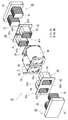
- FIG. 3 is an exploded perspective view of the reactor combination shown in the first embodiment.
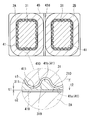
- FIG. 3 is a cross-sectional view taken along the line III-III in FIG. 1 and a partially enlarged view thereof. It is the elements on larger scale which show the positional relationship of the inner side interposed member provided with the intervention side recessed part different from FIG. 3, the inner core part arrange
- an object of the present disclosure is to provide a reactor having excellent heat dissipation. Another object of the present disclosure is to provide a small reactor having excellent magnetic characteristics.
- the inner intervening member is often formed by injection molding.
- the dimensions of the injection-molded product are likely to vary when the thickness of the inner interposed member is reduced. Therefore, conventionally, the thickness of the inner interposed member is set to a certain value (for example, 2.5 mm or more), or the inner interposed member is provided with ribs as described in Patent Documents 1 and 2, for example. Increasing accuracy is being done. However, in such a configuration, the distance between the winding part and the inner core part becomes large. Therefore, heat dissipation from the inner core part to the winding part is limited, and when the cross-sectional area of the winding part is constant, the magnetic path cross-sectional area of the inner core part arranged inside the winding part is It cannot be larger than a certain level. In view of these points, the present inventors have completed the reactor according to the embodiment described below.
- the reactor according to the embodiment is A coil having a winding part; A magnetic core having an inner core portion disposed inside the winding portion; An inner interposed member that secures insulation between the wound portion and the inner core portion, and a reactor comprising:
- the inner interposed member includes a thin portion whose thickness is reduced by recessing the inner peripheral surface side, and a thick portion whose thickness is thicker than the thin portion,
- the inner core portion includes a core-side convex portion having a shape along the inner peripheral surface shape of the thin-walled portion on an outer peripheral surface facing the inner interposed member.
- the thickness of the thin part is 0.2 mm or more and 1.0 mm or less
- the thickness of the thick part is 1.1 mm or more and 2.5 mm or less
- the resin injected into the part where the mold gap is wide is thick and the resin injected into the part where the mold gap is narrow is thin. Part.
- the portion where the gap between the molds is wide serves to quickly spread the resin over the entire gap between the molds. Therefore, even if it has a thin part thinner than the conventional thickness, an inner interposition member having a thick part greater than or equal to a predetermined thickness is easy to produce according to the design dimensions.
- the inner interposed member is designed so that the clearance between the inner core portion and the inner interposed member and between the inner interposed member and the winding portion is reduced if the variation in the size of the inner interposed member is small, Problems such as failure to insert the inner interposition member into the turning portion and failure to insert the inner core portion into the inner interposition member can be suppressed.
- the distance from the inner core portion to the winding portion can be reduced, and the heat dissipation from the inner core portion to the winding portion can be improved.
- the core-side convex portion of the inner core portion is disposed in the dent of the thin-walled portion (hereinafter sometimes referred to as an intervening concave portion), from the core-side convex portion to the winding portion. As a result, the heat dissipation of the reactor can be improved.
- the magnetic path cross-sectional area of the inner core portion in the winding portion can be increased without increasing the winding portion.
- the magnetic path cross-sectional area of the inner core portion is increased by disposing the core-side convex portion of the inner core portion in the intervening concave portion of the inner interposed member. Therefore, the magnetic path cross-sectional area of the inner core portion can be made larger than that of the reactor using the conventional inner interposed member that does not have the intervening concave portion without changing the size of the winding portion.
- the reactor can independently manufacture the inner core portion, the inner interposed member, and the coil, the shape of each member and the degree of freedom of the manufacturing method are high.
- the high degree of freedom in the manufacturing method has the advantage that existing facilities can be used to manufacture the reactor.
- a mode in which the difference between the thickness of the thin portion and the thickness of the thick portion is 0.2 mm or more can be exemplified.
- the thickness of the said thin part can be mentioned 0.2 mm or more and 0.7 mm or less, and the thickness of the said thick part can be 1.1 mm or more and 2.0 mm or less.
- the thickness of the thin portion By setting the thickness of the thin portion within the above range, the distance between the winding portion and the core-side convex portion of the inner core portion can be sufficiently shortened, and the heat dissipation of the reactor can be further improved. Moreover, the variation of the dimension of an inner interposed member can be made still smaller by making the thickness of a thick part into the said range.
- the thick part and the thin part may include a plurality of dispersed parts in the circumferential direction of the inner interposed member.
- the inner interposition member having the above-described configuration is an inner interposition member with small variations in dimensions, and can improve the heat dissipation and magnetic characteristics of the reactor.
- the resin can more easily spread throughout the gaps of the mold.
- the resin When producing the inner interposed member by injection molding, the resin is often injected from a position that is an end surface of the inner interposed member in the mold. In this case, since the end face of the inner interposed member serves as an inlet for the resin, if there is a large gap corresponding to the thick portion at the inlet of the resin, the moldability of the inner interposed member is improved.
- the inner interposed member having a thick portion reaching the end surface of the inner interposed member is produced, a portion where a gap corresponding to the thick portion is widened is formed at the resin inlet. Therefore, the inner interposed member having the above configuration is excellent in moldability and can be accurately manufactured even if the thickness of the thin portion is small.
- the outer peripheral surface of the inner interposed member may include a shape that is in a shape along the inner peripheral surface of the winding part.
- the outer peripheral surface of the inner interposed member is shaped along the inner peripheral surface shape of the winding portion, the clearance between the outer peripheral surface of the inner interposed member and the inner peripheral surface of the winding portion can be easily reduced. As a result, it is easy to improve the heat dissipation and magnetic characteristics of the reactor.
- the formability of the inner interposed member can be improved by adopting a form in which the thickness of the inner interposed member gradually increases from the thin portion toward the thick portion.
- Examples of the configuration in which the thickness gradually increases from the thin wall portion to the thick wall portion include, for example, a curved surface or an inclined surface from the thin wall portion to the thick wall portion.
- the above-described configuration improves the moldability of the inner interposed member.
- a mode in which the clearances formed between the inner core portion and the inner interposed member and between the inner interposed member and the wound portion are each greater than 0 mm and not greater than 0.3 mm can be exemplified.
- both clearances are more than 0 mm and 0.3 mm or less, the heat dissipation and magnetic properties of the reactor can be further improved.
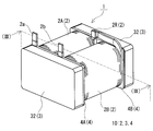
- a reactor 1 shown in FIG. 1 includes a combined body 10 in which a coil 2, a magnetic core 3, and an insulating interposed member 4 are combined.
- One of the features of the reactor 1 is that the shape of a part of the insulating interposed member 4 (inner interposed member 41 in FIGS. 2 and 3 described later) is different from the conventional one.
- each structure of the reactor 1 will be briefly described with reference to FIGS. 1 and 2, and then the shape of the inner interposed member 41, the inner interposed member 41, the magnetic core 3 and the winding portions 2 ⁇ / b> A and 2 ⁇ / b> B disposed inside and outside thereof. The relationship will be described in detail with reference to FIGS.
- the coil 2 in the present embodiment includes a pair of winding portions 2A and 2B arranged in parallel and a connecting portion 2R that connects both the winding portions 2A and 2B. Both end portions 2a and 2b of the coil 2 are drawn out from the winding portions 2A and 2B and connected to a terminal member (not shown). An external device such as a power source for supplying power is connected to the coil 2 through the terminal member.
- the winding portions 2A and 2B provided in the coil 2 of this example are formed in a substantially rectangular tube shape with the same number of turns and the same winding direction, and are arranged in parallel so that the respective axial directions are parallel.
- the number of turns and the cross-sectional area of the winding may be different in each winding part 2A, 2B.
- the connecting portion 2R of the present example is formed by joining the ends of the windings of the winding portions 2A and 2B by welding or pressure bonding.
- the coil 2 may be formed by spirally winding a single winding without a joint.
- the coil 2 including the winding portions 2A and 2B is a coated wire having an insulating coating made of an insulating material on the outer periphery of a conductor such as a flat wire or a round wire made of a conductive material such as copper, aluminum, magnesium, or an alloy thereof. Can be configured.
- the windings 2A and 2B are formed by edgewise winding a rectangular wire made of copper and a conductor made of enamel (typically polyamideimide). Yes.
- the magnetic core 3 of this example is configured by combining two divided cores 3 ⁇ / b> A and 3 ⁇ / b> B whose top view is approximately ⁇ -shaped.
- the magnetic core 3 can be divided into inner core portions 31 and 31 and outer core portions 32 and 32.
- the inner core portion 31 is a portion disposed inside the winding portions 2A and 2B of the coil 2.
- the inner core portion 31 means a portion of the magnetic core 3 along the axial direction of the winding portions 2A and 2B of the coil 2.
- the part which protrudes from the inside of winding part 2A, 2B to the outer side of an end surface is also a part of inner core part 31.
- Each inner core portion 31 of this example is composed of one ⁇ -shaped protrusion of the split core 3A and one ⁇ -shaped protrusion of the split core 3B.
- a plate-shaped gap material may be disposed between the projecting portions.
- the gap material can be made of a nonmagnetic material such as alumina.
- the overall schematic shape of the inner core portion 31 is a shape corresponding to the internal shape of the winding portion 2A (2B), and in this example, is a substantially rectangular parallelepiped shape.
- An uneven shape is formed on the outer peripheral surface of the inner core portion 31 of this example.
- the uneven shape of the outer peripheral surface of the inner core portion 31 corresponds to the inner peripheral surface shape of the inner interposed member 41 described later.
- the detailed configuration of the uneven shape will be described later with reference to FIGS.
- the outer core portion 32 is a portion arranged outside the winding portions 2A and 2B, and has a shape connecting the ends of the pair of inner core portions 31 and 31.
- Each outer core portion 32 in the present example has a flat rectangular parallelepiped shape formed of a ⁇ -shaped root portion of the split core 3A (3B).
- the lower surface of the outer core portion 32 is substantially flush with the lower surfaces of the winding portions 2A and 2B of the coil 2 (see FIG. 1). Of course, both lower surfaces need not be flush with each other.
- the split cores 3A and 3B can be formed of a composite material molded body including soft magnetic powder and resin.
- the soft magnetic powder is an aggregate of magnetic particles composed of an iron group metal such as iron or an alloy thereof (Fe—Si alloy, Fe—Si—Al alloy, Fe—Ni alloy, etc.).
- An insulating coating made of phosphate or the like may be formed on the surface of the magnetic particles.
- the resin include thermosetting resins such as epoxy resin, phenol resin, silicone resin, and urethane resin, polyamide (PA) resin such as polyphenylene sulfide (PPS) resin, nylon 6, and nylon 66, polyimide resin, and fluorine resin.
- a thermoplastic resin such as a resin can be used.
- the content of the soft magnetic powder in the composite material may be 50% by volume or more and 80% by volume or less when the composite material is 100%.
- the magnetic powder is 50% by volume or more, since the ratio of the magnetic component is sufficiently high, it is easy to increase the saturation magnetic flux density.
- the magnetic powder is 80% by volume or less, the mixture of the magnetic powder and resin has high fluidity, and a composite material excellent in moldability can be obtained.
- the lower limit of the content of the magnetic powder is 60% by volume or more.
- the upper limit of content of magnetic body powder is 75 volume% or less, Furthermore, 70 volume% or less is mentioned.
- the split cores 3A and 3B can also be formed of a compacted body obtained by pressure-molding raw material powder containing soft magnetic powder.
- the soft magnetic powder the same soft magnetic powder that can be used for the compact of the composite material can be used. Since the protruding portions of the split cores 3A and 3B are inserted into the inner interposed member 41 of the insulating interposed member 4 to be described later, a resin mold portion is formed on the outer periphery of the green compact to protect the green compact. It doesn't matter.
- the insulating interposing member 4 is a member that ensures insulation between the coil 2 and the magnetic core 3, and is configured by combining a pair of insulating divided pieces 4 ⁇ / b> A and 4 ⁇ / b> B having the same shape in this example.
- the insulating divided piece 4A on the side where the ends 2a and 2b of the winding parts 2A and 2B are arranged and the insulating divided piece 4B on the side where the connecting part 2R is arranged may have different shapes. .
- the insulating divided pieces 4A and 4B are substantially ⁇ -shaped members in which a pair of inner interposed members 41 and 41 formed in a cylindrical shape and a frame-shaped end surface interposed member 42 are integrated.
- the inner interposed members 41, 41 are interposed between the inner peripheral surface of the winding portions 2 ⁇ / b> A, 2 ⁇ / b> B and the outer peripheral surface of the inner core portion 31.
- the end surface interposed member 42 is interposed between the end surfaces of the winding portions 2 ⁇ / b> A and 2 ⁇ / b> B and the outer core portion 32.
- turn storage portions 42 s On the surface of the end surface interposed member 42 on the coil 2 side, two turn storage portions 42 s (particularly refer to the insulating divided pieces 4 B) for storing the axial end portions of the winding portions 2 A and 2 B are formed.
- the turn accommodating portion 42s is a recess along the shape of the end surface in the axial direction of the winding portions 2A and 2B, and is formed to bring the entire end surface into surface contact with the end surface interposed member 42.
- the partition part 42d which is arrange
- the inner interposed members 41 and 41 and the end face interposed member 42 are integrally formed, and a portion indicated by a two-dot chain line of the insulating divided pieces 4A (insulating divided pieces 4A).
- a through hole 41 h formed inside the inner interposed member 41 is opened on the surface of the end surface interposed member 42 on the outer core portion 32 side.
- the opening portion of the through hole 41 h serves as an inlet for inserting the inner core portion 31 into the inner interposed member 41.
- the inner peripheral surface of the inner interposed member 41 constituting the through hole 41h is formed in an uneven shape. This will be described later with reference to FIGS.
- the insulating interposition member 4 having the above-described configuration includes, for example, PPS resin, polytetrafluoroethylene (PTFE) resin, liquid crystal polymer (LCP), PA resin such as nylon 6 and nylon 66, polybutylene terephthalate (PBT) resin, acrylonitrile butadiene -It can be comprised with thermoplastic resins, such as a styrene (ABS) resin.
- the insulating interposed member 4 can be formed of a thermosetting resin such as an unsaturated polyester resin, an epoxy resin, a urethane resin, or a silicone resin.
- the resin may contain a ceramic filler to improve the heat dissipation property of the insulating interposed member 4.
- the ceramic filler for example, nonmagnetic powder such as alumina or silica can be used.
- the reactor 1 of this example is a caseless structure, it can also be set as the structure which has arrange
- ⁇ Relationship between inner interposed member, inner core part and winding part ⁇ 3 is a III-III cross-sectional view orthogonal to the axial direction of the winding portions 2A and 2B in FIG.
- the illustration of the connecting portion 2R is omitted.
- the shape and clearance of each member are exaggerated.
- the inner interposition member 41 has a plurality of intervening recesses 411 formed on the inner peripheral surface 410 thereof.
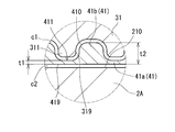
- the inner interposed member 41 includes a thin portion 41a having a reduced thickness due to the inner peripheral surface 410 being recessed by the interposed concave portion 411, and a thick portion 41b having a thickness greater than the thin portion 41a.
- the shape of the inner peripheral surface of the intervening concave portion 411 in the cross section perpendicular to the extending direction of the intervening concave portion 411 is not particularly limited.
- the inner peripheral surface shape of the intervening recess 411 can be a semicircular arc shape, or can be a substantially rectangular shape as shown in FIG. 4.
- the inner peripheral surface shape of the intervening recess 411 may be a V-groove shape or a dovetail shape.
- the thickness t1 of the thin portion 41a is 0.2 mm to 1.0 mm, and the thickness t2 of the thick portion 41b is 1.1 mm to 2.5 mm.
- the thickness t1 of the thin portion 41a is the thickness of the portion corresponding to the deepest position of the intervening recess 411, that is, the minimum thickness in the thin portion 41a, as shown in FIGS. .
- the thickness t1 of the thin wall portion 41a is clearly thinner than the thickness (for example, 2.5 mm) of the conventional inner interposed member having a uniform thickness.
- the thickness t2 of the thick portion 41b is the maximum thickness in a portion where the intervening recess 411 does not exist.
- the resin injected into the portion where the gap of the injection mold is wide is the thick portion 41b, and the resin injected into the portion where the mold gap is narrow is It becomes the thin part 41a.
- the portion where the gap between the molds is wide serves to quickly spread the resin over the entire gap between the molds. Therefore, even if the thin portion 41a having a smaller thickness than the conventional one is provided, the inner interposed member 41 having the thick portion 41b having a predetermined thickness or more is easily manufactured according to the design dimensions.
- the inner interposed member 41 can be designed so as to be. Even if both the clearances c1 and c2 are reduced, the inner interposed member 41 cannot be inserted into the winding portions 2A and 2B because the dimensional accuracy of the inner interposed member 41 is high, or the inner core portion 31 is not inserted into the inner interposed member 41. It is difficult to cause troubles such as being unable to insert.
- the plurality of interposed concave portions 411 are preferably dispersed in the circumferential direction of the inner peripheral surface 410 of the inner interposed member 41.
- this configuration is a configuration in which a plurality of thick portions 41 b and thin portions 41 a are dispersed in the circumferential direction of the inner interposed member 41.
- the narrow gap portion and the wide gap portion are alternately arranged in the circumferential direction of the gap for injecting the resin in the mold.
- the moldability of the inner interposed member 41 it is preferable that at least a part of the thick portion 41b reaches the end surface of the inner interposed member 41 in the axial direction of the winding portions 2A and 2B. It is preferable that all the thick portions 41b reach the end surface of the inner interposed member 41 as shown in FIG.
- the resin is often injected from a position that is an end surface of the inner interposed member 41 in the mold. In this case, the moldability of the inner intervening member 41 is improved when the gap between the molds at the position to be the resin inlet is large. That is, the inner interposed member 41 including the thick portion 41b reaching the end surface of the inner interposed member 41 is excellent in moldability and can be accurately manufactured even if the thin portion 41a is thin.
- the inner core portion 31 disposed inside the inner interposed member 41 includes a core-side convex portion 311 formed on the outer peripheral surface (core outer peripheral surface 319) (see FIG. 5 together). reference).
- the core-side convex portion 311 has a shape corresponding to the interposition-side concave portion 411 formed on the inner peripheral surface 410 of the inner interposition member 41.
- the thin portion 41a of the inner interposed member 41 in which the intervening recess 411 is formed is thinner than the conventional inner interposed member having a uniform thickness. Therefore, the magnetic path cross-sectional area of the inner core portion 31 including the core-side convex portion 311 disposed in the intervening concave portion 411 is surely larger than the conventional inner core portion by the core-side convex portion 311.
- the core-side convex portion 311 is preferably formed so that the inner clearance c1 is substantially constant both at the position of the thin portion 41a and the position of the thick portion 41b. Further, the constant inner clearance c1 can be set to more than 0 mm and 0.3 mm or less because the inner interposed member 41 can be easily manufactured according to the design dimensions. Since the inner clearance c1 can be reduced, the distance from the inner core portion 31 to the winding portions 2A and 2B can be reduced, and the heat dissipation from the inner core portion 31 to the winding portions 2A and 2B can be improved.
- the inner clearance c1 can be reduced, if the winding portions 2A and 2B have the same size, the magnetic path cross-sectional area of the inner core portion 31 can be increased as compared with the case where the conventional inner interposed member is used. Ease of insertion of the inner core portion 31 into the through hole 41h of the inner interposed member 41, an effect of improving heat dissipation from the inner core portion 31 to the winding portions 2A and 2B, and a magnetic path cross-sectional area of the inner core portion 31 In consideration of the effect of increasing the inner clearance c1, the inner clearance c1 is preferably 0.2 mm or less, more preferably 0.1 mm or less.
- the outer peripheral surface 419 of the inner interposed member 41 has a shape along the inner peripheral surface shape of the winding portions 2A and 2B. By doing so, it is easy to reduce the outer clearance c2 between the outer peripheral surface 419 of the inner interposed member 41 and the coil inner peripheral surface 210 of the winding portions 2A and 2B. Specifically, the outer clearance c2 is easily set to be greater than 0 mm and equal to or less than 0.3 mm.
- the outer clearance c2 can be reduced, the distance from the inner core portion 31 to the winding portions 2A and 2B can be reduced, the heat dissipation from the inner core portion 31 to the winding portions 2A and 2B can be improved, and the inner side The cross-sectional area of the magnetic path of the core part 31 can be increased. Ease of inserting the inner interposed member 41 into the winding parts 2A, 2B, the effect of improving the heat dissipation from the inner core part 31 to the winding parts 2A, 2B, and the magnetic path cross-sectional area of the inner core part 31
- the outer clearance c2 is preferably 0.2 mm or less, more preferably 0.1 mm or less in consideration of the effect of increasing the above.
- the thickness t1 of the thin part 41a and the thickness t2 of the thick part 41b The difference (thickness t2 ⁇ thickness t1) is preferably 0.2 mm or more. If the thin portion 41a and the thick portion 41b are defined by specific numerical values, the thickness t1 of the thin portion 41a is 0.2 mm or more and 0.7 mm or less, and the thickness t2 of the thick portion 41b is 1.1 mm or more. The thickness t1 of the thin portion 41a is preferably 0.2 mm or more and 0.5 mm or less, and the thickness t2 of the thick portion 41b is more preferably 1.1 mm or more and 2.0 mm or less.
- the formability of the inner interposed member 41 can be improved by making the thickness of the inner interposed member 41 gradually increase from the thin portion 41a toward the thick portion 41b. This is because when the inner interposed member 41 is injection-molded, the resin injected into the portion that becomes the thick portion 41b in the mold easily flows into the portion that becomes the thin portion 41a.
- the width direction edge of the thin portion 41 a is recessed outward of the inner interposed member 41. It is mentioned to make it a rounded shape.
- the width direction edge of the thick part 41 b (the edge in the direction in which the thin part 41 a is present) has a rounded shape that protrudes outward of the inner interposed member 41.
- the said width direction edge part can be made into circular arc shape, In that case, the curvature radius of circular arc can be 0.05 mm or more and 20 mm or less, Furthermore, 0.1 mm or more and 10 mm or less can be used.
- the radius of curvature of the arc is large, as shown in FIG. 3, the edge in the width direction of the thin portion 41 a and the edge in the width direction of the thick portion 41 b are connected, and the inner peripheral surface 410 of the inner interposed member 41 is formed. Waveform shape.
- the inner peripheral surface 410 of the inner interposed member 41 has a shape in which intervening recesses 411 having rectangular grooves with rounded corners are arranged.
- a V-groove-shaped intervening concave portion 411 having rounded corners may be arranged in a line.
- the thick portion 41b is different from the end surface on one end side in the axial direction of the inner interposed member 41 (same as the axial direction of the winding portions 2A and 2B). It is preferable to have a shape that extends to the end face on the end side.
- the end surface of the inner interposed member 41 serves as an inlet for the resin, so that a large gap corresponding to the thick portion 41b exists at the resin inlet. This is because the moldability of the inner interposed member 41 is improved.
- the shape of the inner interposed member 41 is such that the interposed concave portion 411 (thinned portion 41a) extends from the end surface on one end side to the end surface on the other end side in the axial direction of the inner interposed member 41.
- the inner core portion 31 corresponding to the inner interposed member 41 includes a plurality of core-side convex portions 311 formed on the core outer peripheral surface 319.
- the core-side convex portions 311 in FIG. 5 are formed on the ridges along the axial direction of the inner core portion 31, and each core-side convex portion 311 has a predetermined interval in the circumferential direction of the core outer peripheral surface 319. Has been placed.
- the reactor 1 of the first embodiment can be manufactured by separately manufacturing and combining the coil 2, the split cores 3A and 3B, and the insulating split pieces 4A and 4B. Specifically, inside the winding portions 2A and 2B of the coil 2 are inserted the inner interposed members 41 and 41 of the insulating divided pieces 4A and 4B, and into the through holes 41h and 41h of the inner interposed members 41 and 41, The protruding portions of the split cores 3A and 3B are inserted. A gap material may be sandwiched between a pair of protruding portions to be faced.
- segmentation state of the insulation interposition member 4 is not necessarily limited to the illustration of Embodiment 1.
- FIG. For example, a substantially ⁇ -shaped divided piece composed of one end surface interposed member 42 and a pair of inner interposed members 41, 41 extending over the entire length of the winding portions 2A, 2B, and the other end surface interposed member 42. It is good also as the insulation interposition member 4 combining the plate-shaped division
- the insulating interposition member 4 may be combined.
- the inner interposed member 41 may be a combination of one end-side cylinder piece and the other end-side cylinder piece that are divided in the axial direction, and each cylinder piece may be fitted from both end surfaces of the inner core portion 31. With this configuration, the inner interposed member 41 can be attached to the inner core portion 31 having the configuration shown in FIG.
- the inner intervening member 41 can also be configured by combining divided pieces obtained by dividing the inner intervening member 41 vertically or horizontally.
- the inner interposed member 41 can be configured by combining divided pieces obtained by dividing the inner interposed member 41 vertically and horizontally. In the case of the latter, it can also be set as an inner interposition member provided with the inner peripheral surface corresponding to the inner core part 31 as shown in FIG.
- the inner core portion 31 in FIG. 6 is configured such that the core-side convex portion 311 on one end side in the axial direction of the inner core portion 31 and the core-side convex portion 311 on the other end side are shifted in the circumferential direction of the inner core portion 31. Is provided.
- the four divided pieces of the inner interposition member corresponding to the inner core portion 31 have an intervening recess on one end side in the axial direction of the inner interposition member and an intervening recess on the other end on the inner peripheral surface.
- the structure shifted in the circumferential direction of the member is provided.
- the intervening concave portion on one end side and the intervening concave portion on the other end side may overlap in the axial direction of the inner intervening member so as to mesh with each other.
- the inner core portion 31 may be inserted into the winding portions 2A and 2B (FIG. 2).
- Embodiment 2 In the first embodiment, the mode in which the coil 2 includes the pair of winding portions 2A and 2B has been described. On the other hand, also in a reactor provided with the coil which has one winding part, the structure similar to Embodiment 1 is employable.
- the magnetic core When using a coil having one winding part, the magnetic core may be configured by combining two divided cores whose shape when viewed from above is approximately E-shaped. In this case, the middle protruding portion of the E of the split core is inserted into the inner interposed member to form the inner core portion. Moreover, an outer core part is formed in parts other than the protrusion part in the middle of E character of a split core. Needless to say, the division state of the magnetic core is not limited to the E-shape.
- an inner interposition member having a thin portion and a thick portion may be interposed between the winding portion and the inner core portion.
- the reactor of the embodiment can be used for a power conversion device such as a bidirectional DC-DC converter mounted on an electric vehicle such as a hybrid vehicle, an electric vehicle, or a fuel cell vehicle.
- a power conversion device such as a bidirectional DC-DC converter mounted on an electric vehicle such as a hybrid vehicle, an electric vehicle, or a fuel cell vehicle.
Landscapes
- Engineering & Computer Science (AREA)
- Power Engineering (AREA)
- Manufacturing & Machinery (AREA)
- Insulating Of Coils (AREA)
Abstract
巻回部を有するコイルと、前記巻回部の内部に配置される内側コア部を有する磁性コアと、前記巻回部と前記内側コア部との間の絶縁を確保する内側介在部材と、を備えるリアクトルであって、前記内側介在部材は、その内周面側が凹むことで厚みが薄くなった薄肉部と、前記薄肉部よりも厚みが厚くなった厚肉部と、を備え、前記内側コア部は、前記内側介在部材に対向する外周面に、前記薄肉部の内周面形状に沿った形状を有するコア側凸部を備え、前記薄肉部の厚さが0.2mm以上1.0mm以下、前記厚肉部の厚さが1.1mm以上2.5mm以下で、前記内側コア部と前記内側介在部材との間の少なくとも一部、および前記内側介在部材と前記巻回部との間の少なくとも一部にクリアランスがあるリアクトル。
Description
本発明は、リアクトルに関する。
本出願は、2017年2月28日付の日本国出願の特願2017-035998に基づく優先権を主張し、前記日本国出願に記載された全ての記載内容を援用するものである。
本出願は、2017年2月28日付の日本国出願の特願2017-035998に基づく優先権を主張し、前記日本国出願に記載された全ての記載内容を援用するものである。
例えば特許文献1,2には、ハイブリッド自動車などの電動車両のコンバータに利用される磁性部品であるリアクトルが開示されている。特許文献1,2のリアクトルは、一対の巻回部を有するコイル、一部が巻回部の内部に配置される磁性コア、およびコイルと磁性コアとの間の絶縁を確保するボビン(絶縁介在部材)を備える。
本開示に係るリアクトルは、
巻回部を有するコイルと、
前記巻回部の内部に配置される内側コア部を有する磁性コアと、
前記巻回部と前記内側コア部との間の絶縁を確保する内側介在部材と、を備えるリアクトルであって、
前記内側介在部材は、その内周面側が凹むことで厚みが薄くなった薄肉部と、前記薄肉部よりも厚みが厚くなった厚肉部と、を備え、
前記内側コア部は、前記内側介在部材に対向する外周面に、前記薄肉部の内周面形状に沿った形状を有するコア側凸部を備え、
前記薄肉部の厚さが0.2mm以上1.0mm以下、前記厚肉部の厚さが1.1mm以上2.5mm以下で、
前記内側コア部と前記内側介在部材との間の少なくとも一部、および前記内側介在部材と前記巻回部との間の少なくとも一部にクリアランスがある。
巻回部を有するコイルと、
前記巻回部の内部に配置される内側コア部を有する磁性コアと、
前記巻回部と前記内側コア部との間の絶縁を確保する内側介在部材と、を備えるリアクトルであって、
前記内側介在部材は、その内周面側が凹むことで厚みが薄くなった薄肉部と、前記薄肉部よりも厚みが厚くなった厚肉部と、を備え、
前記内側コア部は、前記内側介在部材に対向する外周面に、前記薄肉部の内周面形状に沿った形状を有するコア側凸部を備え、
前記薄肉部の厚さが0.2mm以上1.0mm以下、前記厚肉部の厚さが1.1mm以上2.5mm以下で、
前記内側コア部と前記内側介在部材との間の少なくとも一部、および前記内側介在部材と前記巻回部との間の少なくとも一部にクリアランスがある。
[本開示が解決しようとする課題]
近年の電動車両の発達に伴い、リアクトルの性能の向上が求められている。例えば、リアクトルの放熱性を高めることで、リアクトルに熱が籠ることによるリアクトルの磁気特性の変化を抑制することが求められている。また、リアクトルには、小型で磁気特性に優れることが求められている。このような要請に応えるべく、リアクトルの構成の再検討が行なわれている。
近年の電動車両の発達に伴い、リアクトルの性能の向上が求められている。例えば、リアクトルの放熱性を高めることで、リアクトルに熱が籠ることによるリアクトルの磁気特性の変化を抑制することが求められている。また、リアクトルには、小型で磁気特性に優れることが求められている。このような要請に応えるべく、リアクトルの構成の再検討が行なわれている。
そこで、本開示は、放熱性に優れるリアクトルを提供することを目的の一つとする。また、本開示は、小型で磁気特性に優れるリアクトルを提供することを目的の一つとする。
[本願発明の実施形態の説明]
最初に本願発明の実施態様を列記して説明する。
最初に本願発明の実施態様を列記して説明する。
内側介在部材は、射出成形によって形成されることが多い。射出成形品の寸法は、内側介在部材の厚みが薄くなるとバラツキ易い。そのため、従来は、内側介在部材の厚みを一定以上(例えば2.5mm以上)としたり、特許文献1,2に記載のように、内側介在部材にリブを設けるなどして、内側介在部材の寸法精度を上げることが行なわれている。しかし、このような構成では、巻回部と内側コア部の距離が大きくなってしまう。そのため、内側コア部から巻回部への放熱性には制約があり、巻回部の断面積を一定とした場合に、巻回部の内部に配置される内側コア部の磁路断面積を一定以上大きくすることができない。本願発明者らは、これらの点に鑑みて、以下に示す実施形態に係るリアクトルを完成させた。
<1>実施形態に係るリアクトルは、
巻回部を有するコイルと、
前記巻回部の内部に配置される内側コア部を有する磁性コアと、
前記巻回部と前記内側コア部との間の絶縁を確保する内側介在部材と、を備えるリアクトルであって、
前記内側介在部材は、その内周面側が凹むことで厚みが薄くなった薄肉部と、前記薄肉部よりも厚みが厚くなった厚肉部と、を備え、
前記内側コア部は、前記内側介在部材に対向する外周面に、前記薄肉部の内周面形状に沿った形状を有するコア側凸部を備え、
前記薄肉部の厚さが0.2mm以上1.0mm以下、前記厚肉部の厚さが1.1mm以上2.5mm以下で、
前記内側コア部と前記内側介在部材との間の少なくとも一部、および前記内側介在部材と前記巻回部との間の少なくとも一部にクリアランスがある。
巻回部を有するコイルと、
前記巻回部の内部に配置される内側コア部を有する磁性コアと、
前記巻回部と前記内側コア部との間の絶縁を確保する内側介在部材と、を備えるリアクトルであって、
前記内側介在部材は、その内周面側が凹むことで厚みが薄くなった薄肉部と、前記薄肉部よりも厚みが厚くなった厚肉部と、を備え、
前記内側コア部は、前記内側介在部材に対向する外周面に、前記薄肉部の内周面形状に沿った形状を有するコア側凸部を備え、
前記薄肉部の厚さが0.2mm以上1.0mm以下、前記厚肉部の厚さが1.1mm以上2.5mm以下で、
前記内側コア部と前記内側介在部材との間の少なくとも一部、および前記内側介在部材と前記巻回部との間の少なくとも一部にクリアランスがある。
金型内に樹脂を注入する射出成形で内側介在部材を作製する場合、金型の隙間が広い箇所に注入された樹脂が厚肉部、金型の隙間が狭い箇所に注入された樹脂が薄肉部となる。金型の隙間が広い部分は、金型の隙間全体に樹脂を素早く行き渡らせる機能を果たす。そのため、従来よりも厚みが薄い薄肉部を備えていても、所定厚さ以上の厚肉部を備える内側介在部材は、設計寸法通りに作製し易い。内側介在部材の寸法のバラツキが小さいと、内側コア部と内側介在部材との間、および内側介在部材と巻回部との間のクリアランスが小さくなるように内側介在部材を設計しても、巻回部に内側介在部材を挿入できなかったり、内側介在部材に内側コア部を挿入できなかったりといった不具合を抑制できる。
上記両クリアランスを小さくできることで、内側コア部から巻回部までの距離を小さくでき、内側コア部から巻回部への放熱性を向上させることができる。特に、実施形態のリアクトルでは、薄肉部の凹み(以下、介在側凹部と呼ぶ場合がある)に、内側コア部のコア側凸部が配置されているため、コア側凸部から巻回部までの放熱距離が短く、その結果、リアクトルの放熱性を向上させることができる。
また、上記両クリアランスを小さくできることで、巻回部を大きくすること無く、巻回部内の内側コア部の磁路断面積を大きくすることができる。特に、実施形態のリアクトルでは、内側介在部材の介在側凹部に、内側コア部のコア側凸部が配置されることで、内側コア部の磁路断面積が大きくなっている。そのため、巻回部の大きさを変えることなく、介在側凹部を有さない従来の内側介在部材を用いたリアクトルよりも内側コア部の磁路断面積を大きくできる。
さらに、上記リアクトルは、内側コア部、内側介在部材、およびコイルをそれぞれ独立して製造できるため、各部材の形状やその製造方法の自由度が高い。特に製造方法の自由度が高いことにより、上記リアクトルを製造するにあたり、既存施設を利用することができるという利点がある。
<2>実施形態に係るリアクトルの一形態として、
前記薄肉部の厚さと前記厚肉部の厚さとの差が0.2mm以上である形態を挙げることができる。
前記薄肉部の厚さと前記厚肉部の厚さとの差が0.2mm以上である形態を挙げることができる。
薄肉部と厚肉部との差を0.2mm以上とすることで、薄肉部に対応する金型の狭小箇所への樹脂の充填性をより十分に確保しつつ、内側介在部材の寸法のバラツキを小さくすることができる。
<3>実施形態に係るリアクトルの一形態として、
前記薄肉部の厚さが0.2mm以上0.7mm以下、前記厚肉部の厚さが1.1mm以上2.0mm以下である形態を挙げることができる。
前記薄肉部の厚さが0.2mm以上0.7mm以下、前記厚肉部の厚さが1.1mm以上2.0mm以下である形態を挙げることができる。
薄肉部の厚さを上記範囲とすることで、巻回部と内側コア部のコア側凸部との間の距離を十分に短くでき、リアクトルの放熱性をより向上させることができる。また、厚肉部の厚さを上記範囲とすることで、内側介在部材の寸法のバラツキをより一層、小さくすることができる。
<4>実施形態に係るリアクトルの一形態として、
前記厚肉部と前記薄肉部は、前記内側介在部材の周方向に分散して複数存在する形態を挙げることができる。
前記厚肉部と前記薄肉部は、前記内側介在部材の周方向に分散して複数存在する形態を挙げることができる。
上記構成を備える内側介在部材を作製する金型では、樹脂を注入する際に金型の隙間全体に樹脂が行き渡り易く、寸法のバラツキが小さい内側介在部材を作製し易い。つまり、上記構成を備える内側介在部材は、その寸法のバラツキが小さい内側介在部材であって、リアクトルの放熱性と磁気特性を向上させることができる。特に、金型における樹脂を注入する隙間の周方向に隙間が狭い部分と隙間が広い部分が交互に並んだ状態となっていれば、より一層、金型の隙間全体に樹脂が行き渡り易くなる。このような金型であれば、厚肉部と薄肉部とが内側介在部材の周方向に交互に並んだ内側介在部材を、寸法精度良く作製することができる。
<5>実施形態に係るリアクトルの一形態として、
少なくとも一部の前記厚肉部は、前記巻回部の軸方向における前記内側介在部材の端面に達している形態を挙げることができる。
少なくとも一部の前記厚肉部は、前記巻回部の軸方向における前記内側介在部材の端面に達している形態を挙げることができる。
射出成形で内側介在部材を作製する場合、金型における内側介在部材の端面となる位置から樹脂を注入することが多い。この場合、内側介在部材の端面が樹脂の入口となるため、厚肉部に対応する大きな隙間がその樹脂の入口にあると、内側介在部材の成形性が向上する。ここで、内側介在部材の端面に達する厚肉部を備える内側介在部材を作製する場合、樹脂の入口に、厚肉部に対応する隙間が広くなった部分が形成される。そのため、上記構成の内側介在部材は、成形性に優れ、薄肉部の厚みが薄くても精度良く作製することができる。
<6>実施形態に係るリアクトルの一形態として、
前記内側介在部材の外周面は、前記巻回部の内周面に沿った形状である形態を挙げることができる。
前記内側介在部材の外周面は、前記巻回部の内周面に沿った形状である形態を挙げることができる。
内側介在部材の外周面が巻回部の内周面形状に沿った形状であれば、内側介在部材の外周面と、巻回部の内周面とのクリアランスを小さくし易い。その結果、リアクトルの放熱性と磁気特性を向上させ易い。
<7>実施形態に係るリアクトルの一形態として、
前記薄肉部から前記厚肉部に向かって徐々に前記内側介在部材の厚みが増す形態を挙げることができる。
前記薄肉部から前記厚肉部に向かって徐々に前記内側介在部材の厚みが増す形態を挙げることができる。
内側介在部材の厚みが薄肉部から厚肉部に向かって徐々に増す形態とすることで、内側介在部材の成形性を向上させることができる。厚みが薄肉部から厚肉部に向かって徐々に増す構成には、例えば薄肉部から厚肉部に向かって曲面で構成されていたり、傾斜面で構成されていたりすることが挙げられる。上記構成によって内側介在部材の成形性が向上するのは、内側介在部材を射出成形する際、金型における厚肉部となる部分に注入された樹脂が、薄肉部となる部分に向って流れ込み易くなるからである。
<8>実施形態に係るリアクトルの一形態として、
前記内側コア部と前記内側介在部材との間、および前記内側介在部材と前記巻回部との間に形成される前記クリアランスがそれぞれ、0mm超0.3mm以下である形態を挙げることができる。
前記内側コア部と前記内側介在部材との間、および前記内側介在部材と前記巻回部との間に形成される前記クリアランスがそれぞれ、0mm超0.3mm以下である形態を挙げることができる。
両クリアランスが0mm超0.3mm以下であれば、リアクトルの放熱性と磁気特性をより向上させることができる。
[本願発明の実施形態の詳細]
以下、本願発明のリアクトルの実施形態を図面に基づいて説明する。図中の同一符号は同一名称物を示す。なお、本願発明は実施形態に示される構成に限定されるわけではなく、請求の範囲によって示され、請求の範囲と均等の意味および範囲内の全ての変更が含まれることを意図する。
以下、本願発明のリアクトルの実施形態を図面に基づいて説明する。図中の同一符号は同一名称物を示す。なお、本願発明は実施形態に示される構成に限定されるわけではなく、請求の範囲によって示され、請求の範囲と均等の意味および範囲内の全ての変更が含まれることを意図する。
<実施形態1>
≪全体構成≫
図1に示すリアクトル1は、コイル2と磁性コア3と絶縁介在部材4とを組み合わせた組合体10を備える。このリアクトル1の特徴の一つとして、絶縁介在部材4の一部(後述する図2,3の内側介在部材41)の形状が従来と異なることを挙げることができる。まずリアクトル1の各構成を図1,2に基づいて簡単に説明した後、内側介在部材41の形状や、内側介在部材41と、その内外に配置される磁性コア3および巻回部2A,2Bとの関係について図3~5を参照して詳しく説明する。
≪全体構成≫
図1に示すリアクトル1は、コイル2と磁性コア3と絶縁介在部材4とを組み合わせた組合体10を備える。このリアクトル1の特徴の一つとして、絶縁介在部材4の一部(後述する図2,3の内側介在部材41)の形状が従来と異なることを挙げることができる。まずリアクトル1の各構成を図1,2に基づいて簡単に説明した後、内側介在部材41の形状や、内側介在部材41と、その内外に配置される磁性コア3および巻回部2A,2Bとの関係について図3~5を参照して詳しく説明する。
≪コイル≫
本実施形態におけるコイル2は、並列された一対の巻回部2A,2Bと、両巻回部2A,2Bを連結する連結部2Rと、を備える。コイル2の両端部2a,2bは、巻回部2A,2Bから引き出されて、図示しない端子部材に接続される。この端子部材を介して、コイル2に電力供給を行なう電源などの外部装置が接続される。本例のコイル2に備わる各巻回部2A,2Bは、互いに同一の巻数、同一の巻回方向で概略角筒状に形成され、各軸方向が平行になるように並列されている。各巻回部2A,2Bで巻数や巻線の断面積が異なっても良い。また、本例の連結部2Rは、各巻回部2A,2Bの巻線の端部同士を溶接や圧着などにより接合することで形成されている。このコイル2は、接合部の無い一本の巻線を螺旋状に巻回して形成しても良い。
本実施形態におけるコイル2は、並列された一対の巻回部2A,2Bと、両巻回部2A,2Bを連結する連結部2Rと、を備える。コイル2の両端部2a,2bは、巻回部2A,2Bから引き出されて、図示しない端子部材に接続される。この端子部材を介して、コイル2に電力供給を行なう電源などの外部装置が接続される。本例のコイル2に備わる各巻回部2A,2Bは、互いに同一の巻数、同一の巻回方向で概略角筒状に形成され、各軸方向が平行になるように並列されている。各巻回部2A,2Bで巻数や巻線の断面積が異なっても良い。また、本例の連結部2Rは、各巻回部2A,2Bの巻線の端部同士を溶接や圧着などにより接合することで形成されている。このコイル2は、接合部の無い一本の巻線を螺旋状に巻回して形成しても良い。
巻回部2A,2Bを含むコイル2は、銅やアルミニウム、マグネシウム、あるいはその合金といった導電性材料からなる平角線や丸線などの導体の外周に、絶縁性材料からなる絶縁被覆を備える被覆線によって構成することができる。本実施形態では、導体が銅製の平角線からなり、絶縁被覆がエナメル(代表的にはポリアミドイミド)からなる被覆平角線をエッジワイズ巻きにすることで、各巻回部2A,2Bを形成している。
≪磁性コア≫
本例の磁性コア3は、図2に示すように、上面視した形状が概略π字状の二つの分割コア3A,3Bを組み合わせて構成されている。磁性コア3は、便宜上、内側コア部31,31と、外側コア部32,32と、に分けることができる。
本例の磁性コア3は、図2に示すように、上面視した形状が概略π字状の二つの分割コア3A,3Bを組み合わせて構成されている。磁性コア3は、便宜上、内側コア部31,31と、外側コア部32,32と、に分けることができる。
内側コア部31は、コイル2の巻回部2A,2Bの内部に配置される部分である。ここで、内側コア部31とは、磁性コア3のうち、コイル2の巻回部2A,2Bの軸方向に沿った部分を意味する。例えば、巻回部2A,2Bの内部から端面の外側に突出している部分も、内側コア部31の一部である。
本例の各内側コア部31は、分割コア3Aのπ字の一方の突出部と、分割コア3Bのπ字の一方の突出部とで構成されている。両突出部の間に板状のギャップ材が配置されていても良い。ギャップ材は、例えばアルミナなどの非磁性材料で構成することができる。この内側コア部31の全体的な概略形状は、巻回部2A(2B)の内部形状に対応した形状であって、本例の場合、略直方体状である。
本例の内側コア部31の外周面には、凹凸形状が形成されている。この内側コア部31の外周面の凹凸形状は、後述する内側介在部材41の内周面形状に対応している。当該凹凸形状の詳しい構成については、図3,5を参照し、後ほど説明する。
外側コア部32は、巻回部2A,2Bの外部に配置される部分であって、一対の内側コア部31,31の端部を繋ぐ形状を備える。本例の各外側コア部32は、分割コア3A(3B)のπ字の根元部分で構成されている扁平な直方体状である。この外側コア部32の下面は、コイル2の巻回部2A,2Bの下面とほぼ面一になっている(図1参照)。もちろん、両下面は面一となっていなくても構わない。
分割コア3A,3Bは、軟磁性粉末と樹脂とを含む複合材料の成形体で構成することができる。軟磁性粉末は、鉄などの鉄族金属やその合金(Fe-Si合金、Fe-Si-Al合金、Fe-Ni合金など)などで構成される磁性粒子の集合体である。磁性粒子の表面には、リン酸塩などで構成される絶縁被覆が形成されていても良い。また、樹脂としては、例えば、エポキシ樹脂、フェノール樹脂、シリコーン樹脂、ウレタン樹脂などの熱硬化性樹脂や、ポリフェニレンスルフィド(PPS)樹脂、ナイロン6、ナイロン66といったポリアミド(PA)樹脂、ポリイミド樹脂、フッ素樹脂などの熱可塑性樹脂などを利用できる。
複合材料における軟磁性粉末の含有量は、複合材料を100%とするとき、50体積%以上80体積%以下が挙げられる。磁性体粉末が50体積%以上であることで、磁性成分の割合が十分に高いため、飽和磁束密度を高め易い。磁性体粉末が80体積%以下であると、磁性体粉末と樹脂との混合物の流動性が高く、成形性に優れた複合材料とすることができる。磁性体粉末の含有量の下限は、60体積%以上とすることが挙げられる。また、磁性体粉末の含有量の上限は、75体積%以下、更に70体積%以下とすることが挙げられる。
本例とは異なり、分割コア3A,3Bは、軟磁性粉末を含む原料粉末を加圧成形してなる圧粉成形体で構成することもできる。軟磁性粉末には、複合材料の成形体に使用できる軟磁性粉末と同じものを利用することができる。分割コア3A,3Bの突出部は、後述する絶縁介在部材4の内側介在部材41の内部に挿入されるため、圧粉成形体の外周に樹脂モールド部を形成し、圧粉成形体を保護しても構わない。
≪絶縁介在部材≫
絶縁介在部材4は、コイル2と磁性コア3との間の絶縁を確保する部材であって、本例では同一形状の一対の絶縁分割片4A,4Bを組み合わせて構成される。巻回部2A,2Bの端部2a,2bが配置される側にある絶縁分割片4Aと、連結部2Rが配置される側にある絶縁分割片4Bは、異なる形状を備えていても構わない。
絶縁介在部材4は、コイル2と磁性コア3との間の絶縁を確保する部材であって、本例では同一形状の一対の絶縁分割片4A,4Bを組み合わせて構成される。巻回部2A,2Bの端部2a,2bが配置される側にある絶縁分割片4Aと、連結部2Rが配置される側にある絶縁分割片4Bは、異なる形状を備えていても構わない。
絶縁分割片4A,4Bは、筒状に形成された一対の内側介在部材41,41と、枠状の端面介在部材42と、が一体となった概略π字状の部材である。内側介在部材41,41は、巻回部2A,2Bの内周面と内側コア部31の外周面との間に介在される。端面介在部材42は、巻回部2A,2Bの端面と外側コア部32との間に介在される。
端面介在部材42のコイル2側の面には、巻回部2A,2Bの軸方向端部を収納する二つのターン収納部42s(特に絶縁分割片4Bを参照)が形成されている。ターン収納部42sは、巻回部2A,2Bの軸方向端面の形状に沿った凹みであって、当該端面全体を端面介在部材42に面接触させるために形成されている。また、端面介在部材42のコイル2側の面には、巻回部2A,2Bの間に配置され、巻回部2A,2Bを離隔させる仕切り部42dが設けられている。
ここで、本例の絶縁分割片4A,4Bは、内側介在部材41,41と端面介在部材42とが一体に成形されており、絶縁分割片4Aの二点鎖線で示す部分(絶縁分割片4Aを参照)は、内側介在部材41,41である。そのため、端面介在部材42における外側コア部32側の面には、内側介在部材41の内部に形成される貫通孔41hが開口している。貫通孔41hの開口部は、内側介在部材41の内部に内側コア部31を挿入するための入口となる。貫通孔41hを構成する内側介在部材41の内周面は凹凸形状に形成されている。この点については、図3,4を参照して後ほど説明する。
上記構成を備える絶縁介在部材4は、例えば、PPS樹脂、ポリテトラフルオロエチレン(PTFE)樹脂、液晶ポリマー(LCP)、ナイロン6やナイロン66といったPA樹脂、ポリブチレンテレフタレート(PBT)樹脂、アクリロニトリル・ブタジエン・スチレン(ABS)樹脂などの熱可塑性樹脂で構成することができる。その他、不飽和ポリエステル樹脂、エポキシ樹脂、ウレタン樹脂、シリコーン樹脂などの熱硬化性樹脂などで絶縁介在部材4を形成することができる。上記樹脂にセラミックスフィラーを含有させて、絶縁介在部材4の放熱性を向上させても良い。セラミックスフィラーとしては、例えば、アルミナやシリカなどの非磁性粉末を利用することができる。
≪その他の構成≫
本例のリアクトル1は、ケースレスの構成であるが、ケースの内部に組合体10を配置した構成とすることもできる。
本例のリアクトル1は、ケースレスの構成であるが、ケースの内部に組合体10を配置した構成とすることもできる。
≪内側介在部材と、内側コア部および巻回部との関係≫
図3は、図1における巻回部2A,2Bの軸方向に直交するIII-III断面図である。この図3では、連結部2Rの図示を省略している。また、図3では、各部材の形状やクリアランスを誇張して示している。
図3は、図1における巻回部2A,2Bの軸方向に直交するIII-III断面図である。この図3では、連結部2Rの図示を省略している。また、図3では、各部材の形状やクリアランスを誇張して示している。
図3の丸囲み拡大図に示すように、内側介在部材41は、その内周面410に複数の介在側凹部411が形成されている。内側介在部材41は、介在側凹部411により内周面410が凹むことで厚みが薄くなった薄肉部41aと、薄肉部41aよりも厚みが厚くなった厚肉部41bとを備える。
介在側凹部411の延伸方向(図3の紙面奥行き方向であって、巻回部2A,2Bの軸方向に同じ)に直交する断面における介在側凹部411の内周面形状は特に限定されない。例えば、図3に示すように、介在側凹部411の内周面形状は、半円弧状とすることもできるし、図4に示すように概略矩形状とすることもできる。その他、介在側凹部411の内周面形状は、V溝形状や蟻溝形状としても良い。
薄肉部41aの厚さt1は0.2mm以上1.0mm以下、厚肉部41bの厚さt2は1.1mm以上2.5mm以下とする。ここで、薄肉部41aの厚さt1とは、図3,4に示すように、介在側凹部411の最も深い位置に対応する部分の厚さ、即ち薄肉部41aにおける最小厚さのことである。薄肉部41aの厚さt1は、従来の均一な厚さの内側介在部材の厚さ(例えば、2.5mm)よりも明らかに薄い。また、厚肉部41bの厚さt2とは、介在側凹部411が存在しない部分における最大厚さのことである。
上記構成を備える内側介在部材41を射出成形で作製する場合、射出成形の金型の隙間が広い箇所に注入された樹脂が厚肉部41b、金型の隙間が狭い箇所に注入された樹脂が薄肉部41aとなる。金型の隙間が広い部分は、金型の隙間全体に樹脂を素早く行き渡らせる機能を果たす。そのため、従来よりも厚みが薄い薄肉部41aを備えていても、所定厚さ以上の厚肉部41bを備える内側介在部材41は、設計寸法通りに作製し易い。内側介在部材41の寸法のバラツキが小さいと、内側コア部31と内側介在部材41との間の内側クリアランスc1、および内側介在部材41と巻回部2A,2Bとの間の外側クリアランスc2が小さくなるように内側介在部材41を設計することができる。両クリアランスc1,c2が小さくなるようにしても、内側介在部材41の寸法精度が高いため、巻回部2A,2Bに内側介在部材41を挿入できなかったり、内側介在部材41に内側コア部31を挿入できなかったりといった不具合が生じ難い。
内側介在部材41の成形性を考慮し、複数の介在側凹部411は、内側介在部材41の内周面410の周方向に分散して存在することが好ましい。この構成は言い換えれば、厚肉部41bと薄肉部41aとが、内側介在部材41の周方向に分散して複数存在する構成である。この内側介在部材41を作製する金型では、金型における樹脂を注入する隙間の周方向に隙間が狭い部分と隙間が広い部分が交互に並んだ状態になっている。このような金型であれば、樹脂を注入する際に金型の隙間全体に樹脂が行き渡り易く、寸法のバラツキが小さい内側介在部材41を作製し易い。特に、本例のように、薄肉部41aと厚肉部41bが内側介在部材41の軸方向に沿った構成であれば、成形時の金型内への樹脂の充填が一層容易である。
また、内側介在部材41の成形性を考慮し、少なくとも一部の厚肉部41bが、巻回部2A,2Bの軸方向における内側介在部材41の端面に達していることが好ましい。全部の厚肉部41bが、図2に示すように内側介在部材41の端面に達していることが好ましい。射出成形で内側介在部材41を作製する場合、金型における内側介在部材41の端面となる位置から樹脂を注入することが多い。この場合、樹脂の入口となる位置の金型の隙間が大きいと、内側介在部材41の成形性が向上する。つまり、内側介在部材41の端面に達する厚肉部41bを備える内側介在部材41は、成形性に優れ、薄肉部41aの厚みが薄くても精度良く作製することができる。
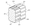
一方、上記内側介在部材41の内部(貫通孔41h)に配置される内側コア部31は、その外周面(コア外周面319)に形成されるコア側凸部311を備える(図5を合わせて参照)。コア側凸部311は、内側介在部材41の内周面410に形成される介在側凹部411に対応する形状を備える。既に述べたように、介在側凹部411が形成される内側介在部材41の薄肉部41aは、従来の厚さが均一な内側介在部材よりも薄い。そのため、介在側凹部411に配置されるコア側凸部311を備える内側コア部31の磁路断面積は、コア側凸部311の分だけ、確実に従来の内側コア部よりも大きくなる。
上記コア側凸部311は、薄肉部41aの位置でも厚肉部41bの位置でも内側クリアランスc1がほぼ一定となるように形成することが好ましい。また、その一定の内側クリアランスc1は、内側介在部材41を設計寸法通りに作製し易いことから、0mm超0.3mm以下とすることができる。内側クリアランスc1を小さくできることで、内側コア部31から巻回部2A,2Bまでの距離を小さくでき、内側コア部31から巻回部2A,2Bへの放熱性を向上させることができる。また、内側クリアランスc1を小さくできることで、巻回部2A,2Bの大きさが同じであれば、従来の内側介在部材を用いた場合よりも、内側コア部31の磁路断面積を大きくできる。内側介在部材41の貫通孔41hへの内側コア部31の挿入のし易さ、内側コア部31から巻回部2A,2Bへの放熱性の向上効果、および内側コア部31の磁路断面積の増加効果を考慮して、内側クリアランスc1は、0.2mm以下、更には0.1mm以下とすることが好ましい。
内側介在部材41の外周面419は、巻回部2A,2Bの内周面形状に沿った形状とすることが好ましい。そうすることで、内側介在部材41の外周面419と、巻回部2A,2Bのコイル内周面210との外側クリアランスc2を小さくし易い。具体的には、外側クリアランスc2を0mm超0.3mm以下とし易い。外側クリアランスc2を小さくできることで、内側コア部31から巻回部2A,2Bまでの距離を小さくでき、内側コア部31から巻回部2A,2Bへの放熱性を向上させることができ、かつ内側コア部31の磁路断面積を大きくできる。巻回部2A,2Bの内部への内側介在部材41の挿入のし易さ、内側コア部31から巻回部2A,2Bへの放熱性の向上効果、および内側コア部31の磁路断面積の増加効果を考慮して、外側クリアランスc2は、0.2mm以下、更には0.1mm以下とすることが好ましい。
[より好ましい構成]
厚肉部41bに対応する金型の隙間が広い部分が、内側介在部材41の成形性を良好にすることを考慮して、薄肉部41aの厚さt1と厚肉部41bの厚さt2との差(厚さt2-厚さt1)を0.2mm以上とすることが好ましい。薄肉部41aと厚肉部41bを具体的な数値で規定するなら、薄肉部41aの厚さt1が0.2mm以上0.7mm以下、厚肉部41bの厚さt2が1.1mm以上2.0mm以下とすることが好ましく、薄肉部41aの厚さt1が0.2mm以上0.5mm以下、厚肉部41bの厚さt2が1.1mm以上2.0mm以下とすることがより好ましい。
厚肉部41bに対応する金型の隙間が広い部分が、内側介在部材41の成形性を良好にすることを考慮して、薄肉部41aの厚さt1と厚肉部41bの厚さt2との差(厚さt2-厚さt1)を0.2mm以上とすることが好ましい。薄肉部41aと厚肉部41bを具体的な数値で規定するなら、薄肉部41aの厚さt1が0.2mm以上0.7mm以下、厚肉部41bの厚さt2が1.1mm以上2.0mm以下とすることが好ましく、薄肉部41aの厚さt1が0.2mm以上0.5mm以下、厚肉部41bの厚さt2が1.1mm以上2.0mm以下とすることがより好ましい。
薄肉部41aから厚肉部41bに向って徐々に内側介在部材41の厚みが増す形態とすることで、内側介在部材41の成形性を向上させることができる。内側介在部材41を射出成形する際、金型における厚肉部41bとなる部分に注入された樹脂が、薄肉部41aとなる部分に流れ込み易くなるからである。上記形態の具体例として、例えば、図3,4に示すように、薄肉部41aの幅方向縁部(厚肉部41bがある方向の縁部)を、内側介在部材41の外方側に凹となる丸みを帯びた形状とすることが挙げられる。さらに、厚肉部41bの幅方向縁部(薄肉部41aがある方向の縁部)を、内側介在部材41の外方側に凸となる丸みを帯びた形状とすることも好ましい。上記幅方向縁部は円弧状とすることができ、その場合、円弧の曲率半径は0.05mm以上20mm以下、更には0.1mm以上10mm以下とすることができる。円弧の曲率半径が大きいと、図3に示すように薄肉部41aの幅方向縁部と厚肉部41bの幅方向縁部とが繋がったようになり、内側介在部材41の内周面410が波形形状となる。円弧の曲率半径が小さいと、図4に示すように、内側介在部材41の内周面410は、角が丸い矩形溝状の介在側凹部411が並んだ形状となる。その他、角が丸いV字溝状の介在側凹部411が並んだ形状としても構わない。
内側介在部材41の内部に内側コア部31を挿入する構成では、厚肉部41bは、内側介在部材41の軸方向(巻回部2A,2Bの軸方向に同じ)における一端側の端面から他端側の端面に及ぶ形状とすることが好ましい。金型における内側介在部材41の端面となる位置から樹脂を注入する場合、内側介在部材41の端面が樹脂の入口となるため、厚肉部41bに対応する大きな隙間がその樹脂の入口にあると、内側介在部材41の成形性が向上するからである。この内側介在部材41の形状を言い換えると、介在側凹部411(薄肉部41a)が、内側介在部材41の軸方向における一端側の端面から他端側の端面に及ぶ形状である。このような内側介在部材41に対応する内側コア部31は、図5に示すように、コア外周面319に形成される複数のコア側凸部311を備える。図5のコア側凸部311は、内側コア部31の軸方向に沿った突条に形成されており、各コア側凸部311は、コア外周面319の周方向に所定の間隔を空けて配置されている。図5に示すコア外周面319を備える内側コア部31を内側介在部材41に挿入する際、内側介在部材41に対して内側コア部31がズレることなく、スムースに内側コア部31を内側介在部材41に挿入することができる。
≪リアクトルの製造方法≫
実施形態1のリアクトル1は、コイル2、分割コア3A,3B、および絶縁分割片4A,4Bを別個に作製し、組み合わせることで作製することができる。具体的には、コイル2の巻回部2A,2Bの内部に、絶縁分割片4A,4Bの内側介在部材41,41を挿入すると共に、内側介在部材41,41の貫通孔41h,41hに、分割コア3A,3Bの突出部を挿入する。突き合わされる一対の突出部の間にギャップ材を挟み込んでも構わない。
実施形態1のリアクトル1は、コイル2、分割コア3A,3B、および絶縁分割片4A,4Bを別個に作製し、組み合わせることで作製することができる。具体的には、コイル2の巻回部2A,2Bの内部に、絶縁分割片4A,4Bの内側介在部材41,41を挿入すると共に、内側介在部材41,41の貫通孔41h,41hに、分割コア3A,3Bの突出部を挿入する。突き合わされる一対の突出部の間にギャップ材を挟み込んでも構わない。
<変形例1-1>
絶縁介在部材4の分割状態は、実施形態1の例示に限定されるわけではない。例えば、一方の端面介在部材42と、巻回部2A,2Bの全長に渡る一対の内側介在部材41,41とで構成される概略π字状の分割片と、他方の端面介在部材42で構成される板状の分割片とを組み合わせて絶縁介在部材4としても良い。また、巻回部2Aの全長に渡る内側介在部材41と、巻回部2Bの全長に渡る内側介在部材41と、一方の端面介在部材42と、他方の端面介在部材42の四つの分割片を組み合わせて絶縁介在部材4としても良い。また、内側介在部材41を軸方向に分割した一端側筒片と他端側筒片の組合せとし、各筒片を内側コア部31の両端面から嵌め込む構成とすることもできる。この構成であれば、後述する図6の構成の内側コア部31に内側介在部材41を装着することもできる。
絶縁介在部材4の分割状態は、実施形態1の例示に限定されるわけではない。例えば、一方の端面介在部材42と、巻回部2A,2Bの全長に渡る一対の内側介在部材41,41とで構成される概略π字状の分割片と、他方の端面介在部材42で構成される板状の分割片とを組み合わせて絶縁介在部材4としても良い。また、巻回部2Aの全長に渡る内側介在部材41と、巻回部2Bの全長に渡る内側介在部材41と、一方の端面介在部材42と、他方の端面介在部材42の四つの分割片を組み合わせて絶縁介在部材4としても良い。また、内側介在部材41を軸方向に分割した一端側筒片と他端側筒片の組合せとし、各筒片を内側コア部31の両端面から嵌め込む構成とすることもできる。この構成であれば、後述する図6の構成の内側コア部31に内側介在部材41を装着することもできる。
その他、内側介在部材41は、内側介在部材41を上下または左右に二分割した分割片を組み合わせて構成することもできる。あるいは、内側介在部材41を上下および左右に四分割した分割片を組み合わせて構成することもできる。後者の場合、図6に示すような内側コア部31に対応する内周面を備える内側介在部材とすることもできる。図6の内側コア部31は、内側コア部31の軸方向の一端側のコア側凸部311と、他端側のコア側凸部311とが、内側コア部31の周方向にズレた構成を備える。この内側コア部31に対応する内側介在部材の四つの分割片は、その内周面における内側介在部材の軸方向の一端側の介在側凹部と、他端側の介在側凹部とが、内側介在部材の周方向にズレた構成を備える。一端側の介在側凹部と他端側の介在側凹部が、噛み合うように内側介在部材の軸方向にオーバーラップしていても構わない。この構成では、四つの分割片は、内側コア部31の径方向外方から内側コア部31に嵌め込んでから、内側コア部31を巻回部2A,2B(図2)内に挿入すると良い。
<実施形態2>
実施形態1では、コイル2が一対の巻回部2A,2Bを備える形態を説明した。これに対して、一つの巻回部を有するコイルを備えるリアクトルにおいても、実施形態1と同様の構成を採用することができる。
実施形態1では、コイル2が一対の巻回部2A,2Bを備える形態を説明した。これに対して、一つの巻回部を有するコイルを備えるリアクトルにおいても、実施形態1と同様の構成を採用することができる。
一つの巻回部を有するコイルを利用する場合、磁性コアは、上面視したときの形状が概略E字状の二つの分割コアを組み合わせて構成すると良い。この場合、分割コアのE字の真ん中の突出部が、内側介在部材の内部に挿入されて内側コア部が形成される。また、分割コアのE字の真ん中の突出部以外の部分で、外側コア部が形成される。言うまでもないが、磁性コアの分割状態は、E字型に限定されるわけではない。
本例の場合も、実施形態1と同様に、薄肉部と厚肉部とを備える内側介在部材を、巻回部と内側コア部との間に介在させると良い。
<用途>
実施形態のリアクトルは、ハイブリッド自動車や電気自動車、燃料電池自動車といった電動車両に搭載される双方向DC-DCコンバータなどの電力変換装置に利用することができる。
実施形態のリアクトルは、ハイブリッド自動車や電気自動車、燃料電池自動車といった電動車両に搭載される双方向DC-DCコンバータなどの電力変換装置に利用することができる。
1 リアクトル
10 組合体
2 コイル
2A,2B 巻回部 2R 連結部 2a,2b 端部
210 コイル内周面
3 磁性コア
3A,3B 分割コア
31 内側コア部 32 外側コア部 311 コア側凸部
319 コア外周面
4 絶縁介在部材
4A,4B 絶縁分割片
41 内側介在部材 41h 貫通孔
410 内周面 411 介在側凹部 419 外周面
41a 薄肉部 41b 厚肉部
42 端面介在部材 42d 仕切り部 42s ターン収納部
c1 内側クリアランス c2 外側クリアランス
10 組合体
2 コイル
2A,2B 巻回部 2R 連結部 2a,2b 端部
210 コイル内周面
3 磁性コア
3A,3B 分割コア
31 内側コア部 32 外側コア部 311 コア側凸部
319 コア外周面
4 絶縁介在部材
4A,4B 絶縁分割片
41 内側介在部材 41h 貫通孔
410 内周面 411 介在側凹部 419 外周面
41a 薄肉部 41b 厚肉部
42 端面介在部材 42d 仕切り部 42s ターン収納部
c1 内側クリアランス c2 外側クリアランス
Claims (8)
- 巻回部を有するコイルと、
前記巻回部の内部に配置される内側コア部を有する磁性コアと、
前記巻回部と前記内側コア部との間の絶縁を確保する内側介在部材と、を備えるリアクトルであって、
前記内側介在部材は、その内周面側が凹むことで厚みが薄くなった薄肉部と、前記薄肉部よりも厚みが厚くなった厚肉部と、を備え、
前記内側コア部は、前記内側介在部材に対向する外周面に、前記薄肉部の内周面形状に沿った形状を有するコア側凸部を備え、
前記薄肉部の厚さが0.2mm以上1.0mm以下、前記厚肉部の厚さが1.1mm以上2.5mm以下で、
前記内側コア部と前記内側介在部材との間の少なくとも一部、および前記内側介在部材と前記巻回部との間の少なくとも一部にクリアランスがあるリアクトル。 - 前記薄肉部の厚さと前記厚肉部の厚さとの差が0.2mm以上である請求項1に記載のリアクトル。
- 前記薄肉部の厚さが0.2mm以上0.7mm以下、前記厚肉部の厚さが1.1mm以上2.0mm以下である請求項1または請求項2に記載のリアクトル。
- 前記厚肉部と前記薄肉部は、前記内側介在部材の周方向に分散して複数存在する請求項1から請求項3のいずれか1項に記載のリアクトル。
- 少なくとも一部の前記厚肉部は、前記巻回部の軸方向における前記内側介在部材の端面に達している請求項1から請求項4のいずれか1項に記載のリアクトル。
- 前記内側介在部材の外周面は、前記巻回部の内周面に沿った形状である請求項1から請求項5のいずれか1項に記載のリアクトル。
- 前記薄肉部から前記厚肉部に向かって徐々に前記内側介在部材の厚みが増す請求項1から請求項6のいずれか1項に記載のリアクトル。
- 前記内側コア部と前記内側介在部材との間、および前記内側介在部材と前記巻回部との間に形成される前記クリアランスがそれぞれ、0mm超0.3mm以下である請求項1から請求項7のいずれか1項に記載のリアクトル。
Priority Applications (2)
| Application Number | Priority Date | Filing Date | Title |
|---|---|---|---|
| CN201880011211.1A CN110326070B (zh) | 2017-02-28 | 2018-02-08 | 电抗器 |
| US16/488,656 US11501907B2 (en) | 2017-02-28 | 2018-02-08 | Reactor |
Applications Claiming Priority (2)
| Application Number | Priority Date | Filing Date | Title |
|---|---|---|---|
| JP2017-035998 | 2017-02-28 | ||
| JP2017035998A JP6611081B2 (ja) | 2017-02-28 | 2017-02-28 | リアクトル |
Publications (1)
| Publication Number | Publication Date |
|---|---|
| WO2018159252A1 true WO2018159252A1 (ja) | 2018-09-07 |
Family
ID=63369962
Family Applications (1)
| Application Number | Title | Priority Date | Filing Date |
|---|---|---|---|
| PCT/JP2018/004414 Ceased WO2018159252A1 (ja) | 2017-02-28 | 2018-02-08 | リアクトル |
Country Status (4)
| Country | Link |
|---|---|
| US (1) | US11501907B2 (ja) |
| JP (1) | JP6611081B2 (ja) |
| CN (1) | CN110326070B (ja) |
| WO (1) | WO2018159252A1 (ja) |
Families Citing this family (2)
| Publication number | Priority date | Publication date | Assignee | Title |
|---|---|---|---|---|
| JP2018142624A (ja) * | 2017-02-28 | 2018-09-13 | 株式会社オートネットワーク技術研究所 | リアクトル |
| JP6611081B2 (ja) * | 2017-02-28 | 2019-11-27 | 株式会社オートネットワーク技術研究所 | リアクトル |
Citations (1)
| Publication number | Priority date | Publication date | Assignee | Title |
|---|---|---|---|---|
| JP2016149453A (ja) * | 2015-02-12 | 2016-08-18 | 株式会社オートネットワーク技術研究所 | リアクトル用コア片、リアクトル用コア片の製造方法、およびリアクトル |
Family Cites Families (12)
| Publication number | Priority date | Publication date | Assignee | Title |
|---|---|---|---|---|
| US3643196A (en) * | 1970-07-10 | 1972-02-15 | Westinghouse Electric Corp | Electrical inductive apparatus |
| CN2743949Y (zh) * | 2004-10-15 | 2005-11-30 | 珠海科德电子有限公司 | 差模/共模一体化电感器 |
| JP4888324B2 (ja) * | 2007-10-17 | 2012-02-29 | トヨタ自動車株式会社 | リアクトルの製造方法 |
| JP5932245B2 (ja) | 2011-06-06 | 2016-06-08 | 株式会社タムラ製作所 | コイル装置用ボビン及びコイル装置 |
| JP5932247B2 (ja) | 2011-06-10 | 2016-06-08 | 株式会社タムラ製作所 | コイル装置用ボビン |
| JP5890334B2 (ja) * | 2013-02-04 | 2016-03-22 | トヨタ自動車株式会社 | リアクトル |
| JP6315256B2 (ja) * | 2013-12-26 | 2018-04-25 | 住友電装株式会社 | リアクトル |
| JP6195229B2 (ja) * | 2014-05-07 | 2017-09-13 | 株式会社オートネットワーク技術研究所 | リアクトル |
| JP6624519B2 (ja) * | 2017-02-28 | 2019-12-25 | 株式会社オートネットワーク技術研究所 | リアクトル |
| JP6611081B2 (ja) * | 2017-02-28 | 2019-11-27 | 株式会社オートネットワーク技術研究所 | リアクトル |
| JP6624520B2 (ja) * | 2017-02-28 | 2019-12-25 | 株式会社オートネットワーク技術研究所 | リアクトル |
| JP6937992B2 (ja) * | 2017-06-08 | 2021-09-22 | 株式会社オートネットワーク技術研究所 | リアクトル |
-
2017
- 2017-02-28 JP JP2017035998A patent/JP6611081B2/ja active Active
-
2018
- 2018-02-08 CN CN201880011211.1A patent/CN110326070B/zh active Active
- 2018-02-08 US US16/488,656 patent/US11501907B2/en active Active
- 2018-02-08 WO PCT/JP2018/004414 patent/WO2018159252A1/ja not_active Ceased
Patent Citations (1)
| Publication number | Priority date | Publication date | Assignee | Title |
|---|---|---|---|---|
| JP2016149453A (ja) * | 2015-02-12 | 2016-08-18 | 株式会社オートネットワーク技術研究所 | リアクトル用コア片、リアクトル用コア片の製造方法、およびリアクトル |
Also Published As
| Publication number | Publication date |
|---|---|
| US11501907B2 (en) | 2022-11-15 |
| CN110326070B (zh) | 2020-12-22 |
| JP2018142623A (ja) | 2018-09-13 |
| CN110326070A (zh) | 2019-10-11 |
| JP6611081B2 (ja) | 2019-11-27 |
| US20200243247A1 (en) | 2020-07-30 |
Similar Documents
| Publication | Publication Date | Title |
|---|---|---|
| JP6624520B2 (ja) | リアクトル | |
| US20190259532A1 (en) | Reactor and reactor manufacturing method | |
| JP6478065B2 (ja) | リアクトル、およびリアクトルの製造方法 | |
| US11282626B2 (en) | Reactor | |
| JP6611081B2 (ja) | リアクトル | |
| JP7072788B2 (ja) | リアクトル | |
| CN110326069B (zh) | 电抗器 | |
| WO2019168152A1 (ja) | リアクトル、及びリアクトルの製造方法 | |
| JP6881652B2 (ja) | リアクトル | |
| WO2017213196A1 (ja) | リアクトル、およびリアクトルの製造方法 | |
| CN111344822B (zh) | 电抗器 | |
| JP6899079B2 (ja) | リアクトル | |
| JP6899999B2 (ja) | リアクトル | |
| WO2019168151A1 (ja) | リアクトル | |
| WO2019181480A1 (ja) | リアクトル | |
| WO2019235186A1 (ja) | リアクトル | |
| CN112970080B (zh) | 电抗器 | |
| WO2020085052A1 (ja) | リアクトル |
Legal Events
| Date | Code | Title | Description |
|---|---|---|---|
| 121 | Ep: the epo has been informed by wipo that ep was designated in this application |
Ref document number: 18761202 Country of ref document: EP Kind code of ref document: A1 |
|
| NENP | Non-entry into the national phase |
Ref country code: DE |
|
| 122 | Ep: pct application non-entry in european phase |
Ref document number: 18761202 Country of ref document: EP Kind code of ref document: A1 |