WO2018155391A1 - ガス化装置 - Google Patents
ガス化装置 Download PDFInfo
- Publication number
- WO2018155391A1 WO2018155391A1 PCT/JP2018/005816 JP2018005816W WO2018155391A1 WO 2018155391 A1 WO2018155391 A1 WO 2018155391A1 JP 2018005816 W JP2018005816 W JP 2018005816W WO 2018155391 A1 WO2018155391 A1 WO 2018155391A1
- Authority
- WO
- WIPO (PCT)
- Prior art keywords
- char
- gasification furnace
- discharge port
- cylindrical portion
- gasification
- Prior art date
- Legal status (The legal status is an assumption and is not a legal conclusion. Google has not performed a legal analysis and makes no representation as to the accuracy of the status listed.)
- Ceased
Links
Images


Classifications
-
- C—CHEMISTRY; METALLURGY
- C10—PETROLEUM, GAS OR COKE INDUSTRIES; TECHNICAL GASES CONTAINING CARBON MONOXIDE; FUELS; LUBRICANTS; PEAT
- C10J—PRODUCTION OF PRODUCER GAS, WATER-GAS, SYNTHESIS GAS FROM SOLID CARBONACEOUS MATERIAL, OR MIXTURES CONTAINING THESE GASES; CARBURETTING AIR OR OTHER GASES
- C10J3/00—Production of combustible gases containing carbon monoxide from solid carbonaceous fuels
- C10J3/02—Fixed-bed gasification of lump fuel
- C10J3/20—Apparatus; Plants
- C10J3/32—Devices for distributing fuel evenly over the bed or for stirring up the fuel bed
-
- C—CHEMISTRY; METALLURGY
- C10—PETROLEUM, GAS OR COKE INDUSTRIES; TECHNICAL GASES CONTAINING CARBON MONOXIDE; FUELS; LUBRICANTS; PEAT
- C10J—PRODUCTION OF PRODUCER GAS, WATER-GAS, SYNTHESIS GAS FROM SOLID CARBONACEOUS MATERIAL, OR MIXTURES CONTAINING THESE GASES; CARBURETTING AIR OR OTHER GASES
- C10J3/00—Production of combustible gases containing carbon monoxide from solid carbonaceous fuels
- C10J3/02—Fixed-bed gasification of lump fuel
- C10J3/20—Apparatus; Plants
- C10J3/34—Grates; Mechanical ash-removing devices
- C10J3/36—Fixed grates
- C10J3/38—Fixed grates with stirring beams
Definitions
- the present invention relates to a gasifier including a gasification furnace that generates a gas by heat-treating a raw material.
- gasifiers that gasify raw materials (typically biomass) are known.
- Such a gasifier is described in Patent Document 1, for example.
- Patent Document 1 discloses a configuration of a gasifier called a fluidized bed type, but as a different system, a fixed bed down is said to have a simple furnace structure and generally generate less tar. Draft gasifiers are known.
- biomass as a raw material charged into the gasifier reacts in the order of pyrolysis, oxidation, and reduction, and gas is generated in the process.
- Carbide (char) generated in the course of these reactions is deposited in the lower part of the gasification furnace, but after a certain amount of time has elapsed, the deposited char is discharged out of the gasification furnace by the discharge device.
- a level sensor is provided at a desired height position of the gasification furnace as described in Patent Document 2, for example, and the detection result of the level sensor is displayed. While monitoring, it is conceivable to adjust the input amount of biomass or adjust the extraction amount of char by the discharge device. However, the amount of char deposited fluctuates under the influence of various factors such as the type and state of biomass and the temperature in the gasifier, so that the control becomes complicated and there is room for improvement.
- the present invention has been made in view of the above circumstances, and an object thereof is to prevent an excessive amount of char from being accumulated in the gasification furnace.
- this gasification apparatus includes a gasification furnace, a container-like cylinder portion, a raw material supply portion, a first discharge port, and a second discharge port.
- the gasification furnace generates a gas by heat-treating a raw material, and carbides generated in the process are deposited.
- the cylindrical portion has a bottom wall disposed in the vicinity of the bottom wall of the gasifier, the side wall extends upward from the bottom wall side of the gasifier, and the top surface is open.
- the raw material supply unit inputs the raw material toward the inside of the cylindrical portion.
- the first discharge port can discharge the carbide from the inside to the outside of the cylindrical portion.
- the second discharge port can discharge the carbide from the outside of the cylindrical portion inside the gasification furnace toward the outside of the gasification furnace.
- biomass when biomass is introduced as a raw material into a gasifier and gas is generated by pyrolysis, oxidation, and reduction, biomass is introduced toward the inside of the cylinder part. It accumulates inside and is discharged to the outside of the gasifier through the first discharge port.
- the carbide when the amount of carbide deposited in the cylinder portion increases to some extent, the carbide overflows from the inside of the cylinder portion, exits to the outside of the cylinder portion, and is discharged from the second outlet to the outside of the gasification furnace. Therefore, it is possible to prevent an excessive amount of carbide from being deposited without precisely controlling the amount of biomass input and the amount of carbide discharged from the outlet. As a result, it can be suppressed with a simple configuration that the residence time of the carbide is too long and unnecessary substances are generated.
- a polygonal pyramid-shaped stirring member is provided at the inner bottom portion of the cylindrical portion so that its apex can be rotated upward.
- the polygonal pyramid-shaped agitating member rotates, so that the inside of the cylinder part is directed from the center to the outside near the bottom, then rises along the inner wall of the cylinder, and reaches the center near the upper surface.
- This vertical circulation promotes that the carbide stays inside the cylinder for a certain amount of time, so it is possible to suppress the residence time of the carbide from becoming too short and to sufficiently gasify the carbide. It becomes.
- an airtight member for maintaining the airtightness inside the gasifier is provided at the second discharge port.
- air can be prevented from entering the gasification furnace from the second outlet, and the deposited carbide can be prevented from being directly exposed to air and combusted at a high temperature. it can.
- the schematic diagram which shows the whole structure of the gasification apparatus which concerns on one Embodiment of this invention.
- FIG. 1 is a schematic diagram showing an overall configuration of a gasifier 1 according to an embodiment of the present invention.
- FIG. 2 is a schematic side view illustrating the gasification furnace 2 provided in the gasification apparatus 1 and the configuration related thereto.
- the gasification apparatus 1 of this embodiment is, for example, organic resources derived from organisms such as agricultural residues such as rice husks and wood-based waste materials (strictly speaking, organic resources excluding fossil fuels. Hereinafter referred to as “biomass”).
- biomass organic resources derived from organisms such as agricultural residues such as rice husks and wood-based waste materials (strictly speaking, organic resources excluding fossil fuels.
- biomass This is a so-called biomass power generation plant that generates gas using fuel (raw material, gasification target) and generates electric power using the gas.
- the gasifier 1 of the present embodiment includes a gasification furnace 2, a raw material supply device (raw material supply unit) 3, a char discharge device 4, a bag filter 5, a gas cooling device 6, a cleaning device 7, An induction blower 8, a control device 9, a cogeneration system 10, and a surplus gas combustion device 11 are provided.
- the gasification furnace 2 shown in FIG. 2 is a furnace in which the main reaction of biomass gasification is performed.
- the gasification furnace 2 of the present embodiment is a so-called fixed bed furnace.
- an oxidant supply port 13 for supplying air or oxygen as an oxidant to the inside of the gasification furnace 2 is provided in the middle of the gasification furnace 2 in the vertical direction.
- a region in which pyrolysis and oxidation (partial combustion) of biomass is performed is formed inside the gasification furnace 2.
- a char deposition region in which char (carbide) remaining after pyrolysis and partial combustion is deposited is formed below the region where partial combustion is performed inside the gasification furnace 2.
- the oxidant supply port 13 is provided in a hole shape at a position corresponding to the region where the partial combustion in the furnace height direction of the gasification furnace 2 is performed so as to communicate the inside and the outside of the gasification furnace 2.
- the raw material supply device 3 supplies biomass from the upper end of the gasification furnace 2 to the inside.
- the raw material supply apparatus 3 of this embodiment includes a hopper, a screw 32, a motor 33, and the like (not shown).
- the hopper is a container into which biomass is charged.
- the screw 32 is rotatably attached to the bottom of the hopper.
- the motor 33 drives the screw 32 to rotate.
- biomass is supplied to the gasification furnace 2 at a desired supply speed by changing the rotation speed of the motor 33 by, for example, inverter control.
- Biomass from the raw material supply device 3 is introduced toward the inside of the cylindrical portion 14 having the first discharge port 19 in the gasification furnace 2.
- the configuration of the cylindrical portion 14 will be described in detail later.
- the char discharge device 4 discharges (extracts) the char from the bottom of the gasification furnace 2 toward the outside of the gasification furnace 2. Strictly speaking, the char discharging device 4 discharges the char from the portion outside the cylindrical portion 14 in the bottom of the gasifying furnace 2 toward the outside of the gasifying furnace 2. Specifically, the char discharge device 4 of the present embodiment extracts the char from the bottom wall of the gasification furnace 2 toward the outside of the gasification furnace 2.
- the char discharge device 4 of the present embodiment includes a second discharge port 43 that can discharge char toward the outside of the gasification furnace 2, and a rotary valve (airtight member) provided on the downstream side of the second discharge port 43. 41 and a screw conveyor 42.
- the second discharge port 43 is a hole provided at the bottom of the gasification furnace 2. Strictly speaking, the second discharge port 43 is provided on the bottom wall of the bottom portion of the gasification furnace 2 that is disposed outside the cylindrical portion 14. The second discharge port 43 connects the inside and the outside of the gasification furnace 2. A passage for guiding the char extracted from the char accumulation region to the screw conveyor 42 is connected to the second discharge port 43.
- the rotary valve 41 is a member for holding the gasification furnace 2 in an airtight state. Further, the rotary valve 41 has a function as a check valve for preventing the char extracted from the gasification furnace 2 from flowing back into the gasification furnace 2.
- the rotary valve 41 rotates to supply the char extracted from the second discharge port 43 to the screw conveyor 42 below.
- the screw conveyor 42 changes the rotation speed thereof, and conveys the extracted char to a predetermined location outside the gasification furnace 2 at a desired speed.
- the biomass (raw material, gasification target) supplied from the raw material supply device 3 is dried.
- the dried biomass is then pyrolyzed in an oxygen-free state at a temperature of about 200 to 600 ° C.
- about 50 to 90% of the biomass is gas (CO, H 2 , CH 4 , CO 2 , H 2 O) and gaseous substances such as tar, and the remaining 10 to 50% is fixed carbon called char.
- Converted to The rate of conversion varies depending on the heating rate in the furnace, the type and particle size of biomass, and the like.
- the pyrolysis product generated by pyrolysis is oxidized (partial combustion) by air or oxygen supplied from the oxidant supply port 13. The heat generated by this partial combustion is used as a heat source in the above pyrolysis.
- the char remaining after the partial combustion is deposited in the char deposition region below the region where the partial combustion is performed.
- the gas generated in the gasification furnace 2 is supplied to the cogeneration system 10 and the surplus gas combustion device 11 through a gas path constituted by piping and the like.
- a gas path constituted by piping and the like.
- the attraction blower 8 are arranged in this order.
- the bag filter 5 removes carbon fine particles such as soot and dust contained in the gas flowing from the gasification furnace 2.
- the bag filter 5 passes gas through the filter of the bag filter 5 using, for example, a method such as centrifugation, and traps soot and dust with this filter.
- the gas cooling device 6 cools the gas that has flowed after passing through the bag filter 5 and increases the density of the gas.
- the gas cooling device 6 cools the gas by using a technique such as heat exchange.
- the gas cooling device 6 includes, for example, a heat exchanger to which cooling water is supplied and a gas path that is piped between the heat exchangers.
- the heat exchanger is supplied with water from a water storage tank as cooling water, and heat is exchanged between the cooling water and the gas.
- the cleaning device 7 cleans the gas that has flowed after being cooled by the gas cooling device 6 to remove tar and the like.
- the cleaning device 7 removes the tar by performing a physical process including, for example, a step of condensing the gaseous tar, a step of separating the gas / liquid mixture, and a step of performing droplet filtration.
- the induction blower 8 induces the gas from the gasification furnace 2 to the cogeneration system 10 side by generating a negative pressure.
- the induction blower 8 is configured by, for example, an induction draft fan. Due to the action of the induction blower 8, a negative pressure is generated in the gas path upstream of the induction blower 8 and in the gasification furnace 2.
- the cogeneration system 10 includes a gas engine and a generator.
- the gas generated in the gasification furnace 2 is supplied to the gas engine after soot and tar are removed and the density is increased, and the thermal energy of the gas is converted into rotational motion by the gas engine. This rotational motion is transmitted to the generator to generate electricity. A part of the heat energy of the gas is used for hot water supply or the like.
- the surplus gas that has not been supplied to the cogeneration system 10 among the gas that has passed through the induction blower 8 is supplied to the surplus gas combustion device 11.
- the surplus gas combustion device 11 incinerates surplus gas, converts carbon monoxide into carbon dioxide, and renders it harmless.
- the control device 9 includes a gasification furnace 2, a raw material supply device 3, a char discharge device 4, a bag filter 5, a gas cooling device 6, a cleaning device 7, an induction blower 8, a cogeneration system 10, a surplus gas combustion device 11, and the like.
- the control device 9 is configured as a computer including a CPU, a ROM, a RAM, and the like, and the CPU can read various programs from the ROM and execute them.
- the ROM stores an appropriate program for causing the gasifier 1 to appropriately gasify biomass.
- the gasification apparatus 1 performs gasification of biomass suitably, the removal of the soot and tar in gas, the concentration of gas, the cogeneration system 10, and the surplus gas combustion apparatus 11 can be supplied with gas.
- the storage unit 12 is a memory that stores numerical values, parameters, and the like used for various controls performed by the control device 9.
- the gasification apparatus 1 configured as described above, after biomass is generated in the gasification furnace 2 using biomass as fuel, soot and tar contained in the gas are removed in the middle of the gas path and concentrated.
- the gas is supplied to the cogeneration system 10. Electric power can be obtained by the thermal energy of the gas. That is, energy using biomass as a resource is converted into electric power and extracted. Thereby, biomass as a renewable energy source can be used effectively.
- a cylindrical portion 14 As a configuration for preventing an excessive amount of char from being accumulated in the char deposition region, a cylindrical portion 14, a first discharge port 19, And a second discharge port 43 and the like.
- a stirring member 15 and the like are provided as a part of a configuration for sufficiently securing the char residence time in the char deposition region.
- the cylindrical portion 14 is a cylindrical member configured in a container shape with a lower end closed and a large upper end. That is, the cylinder portion 14 has a bottomed cylindrical shape.
- a wall (bottom wall) at the lower end of the cylindrical portion 14 has a disc shape, and is disposed in the vicinity of the bottom wall of the bottom of the gasification furnace 2.
- the side wall (cylindrical side wall) of the cylindrical portion 14 extends upward from the peripheral edge portion (the bottom surface side of the gasification furnace 2) of the bottom wall.
- the upper end surface of the cylindrical portion 14 is arranged with its opening facing the raw material supply device 3 side.
- the cylindrical portion 14 is slightly fixed with respect to the bottom surface of the gasification furnace 2 by fixing a plurality of locations on the upper edge of the side wall to the furnace wall 2 a of the gasification furnace 2 via the lifting members 21. It is provided in a state of floating upward.
- a first discharge port 19 is provided at the bottom of the tube portion 14 so that char can be discharged from the inside to the outside of the tube portion 14.
- a first discharge port 19 is provided at the lower end portion of the side wall of the cylindrical portion 14.
- the 1st discharge port 19 is formed in hole shape so that the space inside the cylinder part 14 and space outside may be connected.
- the opening area of the first discharge port 19 is considerably smaller than the opening area of the open portion on the upper side of the cylindrical portion 14.
- the stirring member 15 is disposed inside the cylindrical portion 14 and in the vicinity of the lower end surface thereof.
- the stirring member 15 of this embodiment is formed in the shape of a polygonal pyramid, and has a some ridgeline.
- the stirring member 15 is formed in a quadrangular pyramid shape and has four ridge lines.
- the stirring member 15 should just be formed in the shape of a polygonal pyramid substantially.
- the shape of the stirring member 15 may be, for example, a polygonal frustum shape in which the area of the upper surface is considerably smaller than the area of the bottom surface.
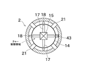
- FIG. 3 is a schematic plan cross-sectional view illustrating the configuration of the inside of the gasification furnace 2, particularly the periphery of the area where char is deposited.
- the stirring member 15 of the present embodiment is disposed at the center of the bottom of the cylindrical portion 14 with its apex facing upward. As shown in FIG. 2, the stirring member 15 is fixed to the upper end portion of the shaft member 16.
- the shaft member 16 is a long shaft-like member that penetrates the central portion of the lower end surface of the cylindrical portion 14 and the central portion of the bottom wall of the gasifier 2.
- the shaft member 16 is provided so as to be rotatable with respect to the bottom portion of the cylindrical portion 14 and the bottom wall of the gasification furnace 2.
- the shaft member 16 is rotationally driven by a drive source such as a motor (not shown).
- the inner stirring blade 17 is a blade provided radially with respect to the axis of the shaft member 16.
- the inner stirring blade 17 is disposed inside the cylindrical portion 14.
- the inner stirring blade 17 of the present embodiment is fixed to the upper end portion of the shaft member 16 via the stirring member 15.
- the char accumulated inside the cylindrical portion 14 is stirred in the cylindrical portion 14.
- the char accumulated inside the cylindrical portion 14 is guided to the first discharge port 19 without being biased and discharged to the outside of the cylindrical portion 14.
- the outer stirring blades 18 are blades provided radially with respect to the axis of the shaft member 16.
- the outer stirring blade 18 is disposed outside the cylindrical portion 14.
- the outer stirring blade 18 of the present embodiment is disposed in a space between the lower end surface of the cylindrical portion 14 and the bottom wall of the gasification furnace 2.
- the outer stirring blade 18 is fixed to the middle part of the shaft member 16 in the vertical direction.
- the outer stirring blade 18 rotates with the rotation of the shaft member 16, whereby the char that has come out of the cylindrical portion 14 is stirred inside the furnace wall 2 a of the gasification furnace 2.
- the char that has been exposed to the outside of the cylindrical portion 14 is guided to the second discharge port 43 without being biased and supplied to the rotary valve 41.
- the char supplied to the rotary valve 41 is supplied to the screw conveyor 42 side as the rotary valve 41 rotates.
- biomass as a raw material is supplied from the raw material supply device 3 toward the inside of the cylindrical portion 14.
- the input biomass and the char generated by the thermal decomposition and partial combustion of the biomass are, as a rule, accumulated inside the cylindrical portion 14.
- Most of the char accumulated inside the cylindrical portion 14 moves away from the axis of the stirring member 15 in the vicinity of the bottom wall of the cylindrical portion 14 due to the rotation of the polygonal pyramid-shaped stirring member 15, and then along the inner wall of the cylindrical portion 14. And flows so as to descend after approaching the axis near the upper surface of the char deposition region (see thin line arrows in FIG. 2).
- at least a part of the char exits outside the cylindrical portion 14 via the first discharge port 19 and then passes through the second discharge port 43 to the outside of the gasifier 2. To be discharged.
- the char when the amount of char accumulated inside the cylinder portion 14 becomes excessive and can no longer be accumulated inside the cylinder portion 14 (specifically, for example, the char has a conical shape at an angle exceeding the repose angle). 2), at least a part of the surplus char is sunk downward in the char accumulation region inside the cylindrical portion 14 and then rises upward (see FIG. 2). (See thin line arrow), and goes out of the cylinder part 14 beyond the upper edge of the side wall of the cylinder part 14. In other words, a part of the char circulates inside the cylinder part 14 and then overflows to the outside of the cylinder part 14.
- the char can be quickly discharged regardless of whether the rotary valve 41 and the screw conveyor 42 are discharged from the first discharge port 19 or overflow from the cylindrical portion 14.
- the gas can be discharged from the second discharge port 43 to the outside of the gasification furnace 2.
- the char flowing by the rotation of the stirring member 15 promotes the char to stay inside the cylinder portion 14 for a certain period of time. In other words, it is possible to prevent the char from being discharged outside the gasification furnace 2 without staying in the char deposition region for a sufficient time. As a result, gasification (reduction) with char can be performed for a sufficient time.
- the residence time of the char can be controlled to some extent by the mechanical structure without performing precise control of the biomass supply amount and the char extraction amount. It is. Therefore, the configuration of the control system of the gasifier 1 can be simplified.
- the gasifier 1 of the present embodiment pyrolyzes biomass, partially burns the pyrolysis product generated by the pyrolysis, and the char remaining after the pyrolysis and the partial combustion. Reduce.
- the gasifier 1 includes a container-shaped cylinder portion 14, a raw material supply device (raw material supply portion) 3, a first discharge port 19, and a second discharge port 43.
- the cylindrical portion 14 has a bottom wall disposed in the vicinity of the bottom wall of the gasification furnace 2 in the inside of the gasification furnace 2, a side wall extending upward from the bottom wall side of the gasification furnace 2, and an upper surface thereof. Is provided in an open state.
- the raw material supply device 3 inputs biomass toward the inside of the cylindrical portion 14.
- the first discharge port 19 allows the char to be discharged from the inside to the outside of the cylindrical portion 14.
- the second discharge port 43 allows the char to be discharged from the outside of the cylindrical portion 14 inside the gasification furnace 2 toward the outside of the gasification furnace 2.
- Biomass is charged toward the inside of the cylindrical portion 14, and therefore, in principle, char is accumulated inside the cylindrical portion 14 and discharged to the outside of the gasification furnace 2 via the first discharge port 19.
- the accumulation amount of char in the cylinder portion 14 increases to some extent, the char in the cylinder portion 14 overflows from the upper edge of the cylinder portion 14 and comes out of the cylinder portion 14, and is gasified from the second discharge port 43. It is discharged outside the furnace 2. Therefore, it is possible to suppress an excessive amount of char deposition without precisely controlling the input amount of biomass and the discharge amount of char from the discharge port 43. As a result, it can be suppressed with a simple structure that the residence time of the char becomes too long and unnecessary substances are generated.
- a polygonal pyramid-shaped stirring member 15 is provided at the bottom inside the cylindrical portion 14 so as to be rotatable with its apex facing upward.
- the polygonal pyramid-shaped stirring member 15 rotates, so that it moves from the center to the outside near the bottom on the inside of the cylinder 14, then rises along the inner wall of the cylinder 14, and near the top surface.
- This vertical circulation prevents the char that has entered the cylindrical portion 14 from being quickly discharged from the first discharge port 19, and promotes the char to stay inside the cylindrical portion 14 for a certain period of time. The For this reason, it becomes possible to suppress that the residence time of char becomes too short, and to perform sufficient gasification (reduction) by char. Therefore, the gasification efficiency can be improved.
- the second exhaust port 43 is provided with a rotary valve (airtight member) 41 for keeping the gas tightness inside the gasification furnace 2.
- the stirring member 15 has a quadrangular pyramid shape, but the shape of the pyramid is not limited to a quadrangular pyramid, and may be, for example, a triangular pyramid or may be five or more pyramids.
- the airtight member is the rotary valve 41.
- the airtight member is not necessarily limited to this.
- a double damper or the like may be used instead. That is, the airtight member may have another configuration as long as it can extract the char in the gasification furnace 2 while maintaining the gastightness in the gasification furnace 2.
- the first discharge port 19 is provided at the lower end portion of the side wall of the cylindrical portion 14, but is not necessarily limited thereto.
- the first discharge port is replaced with the cylindrical portion. It is good also as what forms in the lower end surface of 14 at penetration shape.
- a plurality of first discharge ports 19 can be provided in the cylindrical portion 14.
- the first discharge port 19 is formed in a hole shape that connects the inner space and the outer space of the cylindrical portion 14.
- the first discharge port 19 can be opened and closed. Also good. In that case, for example, immediately after the gasifier 1 is started, the first discharge port 19 is closed until a desired amount of char is deposited inside the cylindrical portion 14, and the char deposition amount reaches the desired amount. It is also possible to start normal control for increasing / decreasing the amount of char deposition with the first discharge port 19 opened later.
- the second discharge port 43 is provided in a penetrating manner in the bottom wall of the gasification furnace 2, but the present invention is not limited to this. It is good also as what forms so that the lower end part of the furnace wall 2a of the conversion furnace 2 may penetrate horizontally. That is, as long as the 2nd discharge port 43 is provided in the bottom part of the gasification furnace 2, it may be formed in the bottom wall and may be formed in the lower end vicinity of the furnace wall 2a.
- the gasification furnace 2 may be provided with a plurality of second discharge ports 43.
- the cylindrical portion 14 is a bottomed cylindrical member, but the shape of the cylindrical portion 14 is not limited to this.
- the cylindrical portion 14 may be, for example, a bottomed polygonal cylindrical shape.
- the gas generated in the gasification furnace 2 is supplied to the cogeneration system 10.
- the present invention is not limited to this.
- the gas generated in the gasification furnace 2 is supplied to the gas turbine. Also good.
- the biomass is dried in the gasification furnace 2, but the present invention is not necessarily limited thereto.
- the biomass is dried in advance before being supplied to the raw material supply device 3. It is good also as what is done.
- the amount of char deposited is controlled by a mechanical structure including the cylindrical portion 14 and the stirring member 15.
- the present invention is not limited to this.
- the control of the char deposition amount is not limited to the electric control for adjusting the biomass supply amount and the electric charge for adjusting the char extraction amount. It may be realized comprehensively by performing general control as well.
- the present invention provides a gasification furnace 2 in which char is deposited below a region where partial combustion is performed, and reduction by the char is performed at a temperature lower than that during partial combustion. It can be widely applied to the gasifier 1 provided. That is, the type of the gasification furnace 2 is not necessarily limited to the fixed bed type.
Landscapes
- Chemical & Material Sciences (AREA)
- Engineering & Computer Science (AREA)
- Mechanical Engineering (AREA)
- Combustion & Propulsion (AREA)
- Oil, Petroleum & Natural Gas (AREA)
- Organic Chemistry (AREA)
- Processing Of Solid Wastes (AREA)
Abstract
ガス化装置は、原料としてのバイオマスを熱分解し、当該熱分解で生成した熱分解生成物質を部分燃焼し、前記熱分解及び前記部分燃焼の後に残った炭化物を還元する。このガス化装置は、容器状の筒部(14)と、原料供給装置(原料供給部)(3)と、第1排出口(19)と、第2排出口(43)と、を備える。筒部(14)は、ガス化炉(2)の内部において、その底壁が当該ガス化炉(2)の底壁の近傍に配置され、その側壁が当該ガス化炉(2)の底壁側から上方に延び、その上面が開放した状態で設けられる。原料供給装置(3)は、筒部(14)の内側に向かってバイオマスを投入する。第1排出口(19)は、筒部(14)の内側から外側に向かって炭化物を排出可能とする。第2排出口(43)は、ガス化炉(2)の内部における筒部(14)の外側から、ガス化炉(2)の外部に向かって、炭化物を排出可能とする。
Description
本発明は、原料を熱処理してガスを発生させるガス化炉を備えるガス化装置に関する。
従来から、原料(典型的には、バイオマス)をガス化するガス化装置が知られている。このようなガス化装置は、例えば特許文献1に記載されている。
特許文献1には流動床式と呼ばれるガス化装置の構成が開示されているが、それとは異なる方式として、炉構造が簡単で、一般的にタールの発生が少ないと言われている固定床ダウンドラフト式ガス化装置が知られている。
固定床ダウンドラフト式ガス化装置において、ガス化炉に投入された原料としてのバイオマスは、熱分解、酸化、還元の順に反応し、その過程でガスが発生する。これらの反応の過程で生成される炭化物(チャー)はガス化炉の下部に堆積するが、ある程度の時間が経過すると、堆積しているチャーは排出装置によってガス化炉の外部に排出される。
上記のようなガス化装置において、近年、チャーがガス化炉の下部に滞留する時間が長過ぎると不要な物質が生成されてしまうおそれがあることが問題視されている。その反面、ガスの発生にチャーも寄与していることから、チャーがガス化炉の下部に滞留する時間が短過ぎると、ガス化効率が低下してしまうことが懸念される。従って、チャーがガス化炉の下部に滞留する時間は適正な長さに調整されることが望ましく、そのためには少なくともガス化炉におけるチャーの堆積量が過剰にならないようにすることが必要と考えられる。
ガス化炉内のチャーの堆積量が過剰にならないようにするため、例えば特許文献2に記載のように、ガス化炉の所望の高さの位置にレベルセンサを設け、レベルセンサの検出結果を監視しながら、バイオマスの投入量を調整したり、排出装置によるチャーの抜出し量を調整したりすることが考えられる。しかしながら、チャーの堆積量は、バイオマスの種類・状態、ガス化炉内の温度等の様々な因子の影響を受けて変動するため、制御が複雑となり、改善の余地があった。
本発明は以上の事情に鑑みてされたものであり、その目的は、ガス化炉内のチャーの堆積量が過剰にならないようにすることにある。
本発明の解決しようとする課題は以上の如くであり、次にこの課題を解決するための手段とその効果を説明する。
本発明の観点によれば、以下の構成のガス化装置が提供される。即ち、このガス化装置は、ガス化炉と、容器状の筒部と、原料供給部と、第1排出口と、第2排出口と、を備える。前記ガス化炉は、原料を熱処理してガスを発生させ、その過程で生成される炭化物が堆積する。前記筒部は、前記ガス化炉の内部において、その底壁が当該ガス化炉の底壁の近傍に配置され、その側壁が当該ガス化炉の底壁側から上方に延び、その上面が開放した状態で設けられる。前記原料供給部は、前記筒部の内側に向かって原料を投入する。前記第1排出口は、前記筒部の内側から外側に向かって前記炭化物を排出可能とする。前記第2排出口は、前記ガス化炉の内部における前記筒部の外側から、前記ガス化炉の外部に向かって、前記炭化物を排出可能とする。
これにより、ガス化炉に原料としてバイオマスを投入して、熱分解、酸化、還元によってガスを発生させるとき、バイオマスは筒部の内側に向かって投入されるため、原則として、炭化物は筒部の内側に堆積し、第1排出口を経由してガス化炉の外部に排出される。しかしながら、筒部内での炭化物の堆積量がある程度大きくなると、炭化物は筒部の内側から溢れて筒部の外側に出て、第2排出口からガス化炉の外部に排出される。よって、バイオマスの投入量や排出口からの炭化物の排出量を精密に制御しなくても、炭化物の堆積量が過大になることを抑制することができる。この結果、炭化物の滞留時間が長くなり過ぎて不要な物質が生成されてしまうことを、簡単な構成で抑制することができる。
前記のガス化装置においては、前記筒部の内側の底部には、多角錘状の撹拌部材がその頂点を上方に向けて回転可能に備えられることが好ましい。
この構成で、多角錐状の撹拌部材が回転することで、筒部の内側において、底部付近では中心部から外側へ向かった後、筒部の内壁に沿って上昇し、上面付近で中心部へ向かった後に下降する炭化物の流れが生じる。この上下方向の循環により、炭化物が筒部の内側にある程度の時間滞留することが促進されるため、炭化物の滞留時間が短くなり過ぎることを抑制し、炭化物の十分なガス化を行うことが可能となる。
前記のガス化装置においては、前記第2排出口には、前記ガス化炉の内部の気密性を保つための気密部材が設けられることが好ましい。
これにより、第2排出口からガス化炉の内部に空気が侵入することを防止することができ、堆積した炭化物が直接的に空気に晒されて高温で燃焼されてしまうことを防止することができる。
次に、図面を参照して本発明の実施の形態を説明する。図1は、本発明の一実施形態に係るガス化装置1の全体的な構成を示す模式図である。図2は、ガス化装置1に備えられるガス化炉2及びそれに関連する構成を説明する側面模式図である。
初めに、本実施形態に係るガス化装置1の全体的な構成について、図1を参照して説明する。
本実施形態のガス化装置1は、例えば、籾殻等の農業残渣や木質系廃材等の生物由来の有機性資源(厳密には、化石燃料を除いた有機性資源。以下、「バイオマス」と称する場合がある。)を燃料(原料、ガス化対象物)としてガスを発生させて、当該ガスを用いて発電する、いわゆるバイオマス発電プラントである。図1に示すように、本実施形態のガス化装置1は、ガス化炉2、原料供給装置(原料供給部)3、チャー排出装置4、バグフィルタ5、ガス冷却装置6、洗浄装置7、誘引ブロワ8、制御装置9、コージェネレーションシステム10、及び余剰ガス燃焼装置11等を備える。
図2に示すガス化炉2は、バイオマスのガス化の主要な反応が行われる炉である。本実施形態のガス化炉2は、いわゆる固定床式炉である。図2に示すように、ガス化炉2の上下方向中途部には、ガス化炉2の内部に酸化剤としての空気又は酸素を供給するための酸化剤供給口13が設けられる。
図2に模式的に示すように、ガス化炉2の内部には、バイオマスの熱分解及び酸化(部分燃焼)が行われる領域が形成されている。また、ガス化炉2の内部の、部分燃焼が行われる領域よりも下方には、熱分解及び部分燃焼の後に残ったチャー(炭化物)が堆積するチャー堆積領域が形成される。酸化剤供給口13は、ガス化炉2の炉高方向の上記部分燃焼が行われる領域に対応する位置に、当該ガス化炉2の内部と外部とを連通するように孔状に設けられる。
原料供給装置3は、ガス化炉2の上端部から内部にバイオマスを供給するものである。本実施形態の原料供給装置3は、図略のホッパ、スクリュー32、及びモータ33等を備えている。前記ホッパは、バイオマスを投入する容器である。スクリュー32は、このホッパの底部に回転可能に取り付けられる。モータ33は、スクリュー32を回転駆動する。本実施形態では、このモータ33の回転速度を例えばインバータ制御によって変化させることにより、バイオマスが所望の供給速度でガス化炉2に供給される。原料供給装置3からのバイオマスは、ガス化炉2内の、第1排出口19を有する筒部14の内側に向かって投入されるようになっている。筒部14の構成については、後で詳しく説明する。
チャー排出装置4は、ガス化炉2の底部から、ガス化炉2の外部に向かってチャーを排出する(抜き出す)ものである。厳密には、チャー排出装置4は、ガス化炉2の底部のうち筒部14の外側の部分から、ガス化炉2の外部に向かってチャーを排出する。具体的には、本実施形態のチャー排出装置4は、ガス化炉2の底壁から当該ガス化炉2の外部に向かってチャーを抜き出す。本実施形態のチャー排出装置4は、ガス化炉2の外部に向かってチャーを排出可能とする第2排出口43と、当該第2排出口43の下流側に設けられるロータリバルブ(気密部材)41と、スクリューコンベア42と、を備えて構成される。
第2排出口43は、ガス化炉2内の底部に設けられる孔である。厳密には、第2排出口43は、ガス化炉2の底部のうち筒部14の外側に配置される底壁に設けられている。第2排出口43は、ガス化炉2の内部と外部とを接続する。当該第2排出口43には、チャー堆積領域から抜き出したチャーをスクリューコンベア42に案内するための通路が接続される。
ロータリバルブ41は、ガス化炉2を気密状態に保持するための部材である。また、ロータリバルブ41は、ガス化炉2から抜き出したチャーが当該ガス化炉2内に逆流することを防止するための逆止弁としての機能を有している。ロータリバルブ41は、回転することにより、第2排出口43から抜き出されたチャーを下方のスクリューコンベア42へと供給する。スクリューコンベア42は、その回転速度が変更されることにより、抜き出されたチャーをガス化炉2の外部の所定の場所へと所望の速度で搬送する。
ガス化炉2内のチャー堆積領域よりも上方の領域では、原料供給装置3から供給されたバイオマス(原料、ガス化対象物)が乾燥される。乾燥されたバイオマスは、その後、200~600℃程度の温度で無酸素状態において熱分解される。これにより、バイオマスの約50~90%がガス(CO、H2、CH4、CO2、H2O)及びタール等のガス状物質に、残りの約10~50%がチャーと呼ばれる固定炭素に転換される。なお、転換の割合は、炉内での加熱速度、バイオマスの種類・粒径等の影響を受けて変動する。熱分解で生成した熱分解生成物質は、酸化剤供給口13から供給された空気又は酸素によって、酸化(部分燃焼)される。この部分燃焼により発生する熱は、上記の熱分解での熱源として利用される。部分燃焼の後に残ったチャーは、部分燃焼が行われる領域よりも下方のチャー堆積領域に堆積される。
ガス化炉2内のチャー堆積領域では、部分燃焼のときよりも概ね低い温度(例えば、700~1000℃)においてチャーによる還元反応(吸着反応)が行われ、これによりチャーが蒸し焼き状態とされてガス化が行われる。このチャー堆積領域でのチャーによるガス化(還元)では、主に以下の反応が行われ、COとH2が生成する。
C+CO2→2CO
C+H2O→H2+CO
C+CO2→2CO
C+H2O→H2+CO
ガス化炉2で生成されたガスは、図1に示すように、配管等により構成されるガス経路を通ってコージェネレーションシステム10及び余剰ガス燃焼装置11に供給される。このガス経路のガス化炉2とコージェネレーションシステム10(余剰ガス燃焼装置11)との間の中途部には、上流側から下流側に向かって、バグフィルタ5、ガス冷却装置6、洗浄装置7、及び誘引ブロワ8がこの順に配置されている。
バグフィルタ5は、ガス化炉2から流れてきたガスに含まれる煤等の炭素の微粒子や、塵等を除去するものである。バグフィルタ5は、例えば遠心分離等の手法を用いて、ガスをバグフィルタ5のフィルタに通し、煤や塵等をこのフィルタで捕捉する。
ガス冷却装置6は、バグフィルタ5を通過した後に流れてきたガスを冷却し、当該ガスの密度を高めるものである。ガス冷却装置6は、例えば熱交換等の手法を用いて、ガスを冷却する。具体的には、ガス冷却装置6は、例えば冷却水が供給される熱交換器と、当該熱交換器の間に配管されるガス経路と、を備えている。熱交換器には冷却水として貯水槽からの水が供給され、冷却水とガスとの間で熱交換が行われる。
洗浄装置7は、ガス冷却装置6で冷却された後に流れてきたガスを洗浄してタール等を除去するものである。洗浄装置7は、例えば、ガス状のタールを凝縮する工程と、ガス・液体混合物を分離する工程と、液滴濾過を行う工程と、を含む物理的プロセスを行うことにより、タールを除去する。
誘引ブロワ8は、負圧を発生させることにより、ガス化炉2からのガスをコージェネレーションシステム10側に誘引するものである。誘引ブロワ8は、例えば誘引通風式の送風機により構成される。誘引ブロワ8の作用により、誘引ブロワ8よりも上流側のガス経路及びガス化炉2内では、負圧が生じている。
コージェネレーションシステム10は、ガスエンジン及び発電機等により構成されるものである。ガス化炉2で生成されたガスが、煤やタール等が除去されて密度が高められた後にガスエンジンに供給されて、当該ガスの熱エネルギーがガスエンジンにより回転運動に変換される。この回転運動が発電機に伝達されて、電気が発生する。またガスの熱エネルギーのうちの一部は、給湯等に用いられる。
誘引ブロワ8を通過した後のガスのうち、コージェネレーションシステム10に供給されなかった余剰のガスは、余剰ガス燃焼装置11に供給される。余剰ガス燃焼装置11は、余剰のガスを焼却処理し、一酸化炭素を二酸化炭素に変換して無害化する。
制御装置9は、ガス化炉2、原料供給装置3、チャー排出装置4、バグフィルタ5、ガス冷却装置6、洗浄装置7、誘引ブロワ8、コージェネレーションシステム10、及び余剰ガス燃焼装置11等を制御するコンピュータである。制御装置9は、CPU、ROM、RAM等を備えたコンピュータとして構成されており、CPUは各種プログラム等をROMから読み出して実行することができる。また、前記ROMには、ガス化装置1に適切にバイオマスのガス化を行わせるための適宜のプログラムが記憶されている。そして、上記したソフトウェアとハードウェアの協働により、ガス化装置1に適宜にバイオマスのガス化を行わせ、ガス中の煤やタールの除去、ガスの濃縮、コージェネレーションシステム10及び余剰ガス燃焼装置11へのガスの供給等を行わせることができる。
記憶部12は、制御装置9が行う様々な制御に用いられる数値や、パラメータ等を記憶するメモリである。
上記のような構成のガス化装置1では、バイオマスを燃料としてガス化炉2内でガスが生成されて、このガスに含まれる煤やタールがガス経路の途中で取り除かれて、濃縮された後に当該ガスがコージェネレーションシステム10に供給される。このガスの熱エネルギーにより電力を得ることができる。即ち、バイオマスを資源としたエネルギーが電力に変換されて取り出される。これにより、再生可能なエネルギー源としてのバイオマスを有効に利用することができる。
ところで、チャーがチャー堆積領域に滞留する時間が長過ぎると不要な物質が生成されてしまうことが、近年問題視されている。その反面、チャーがチャー堆積領域に滞留する時間が短過ぎると、チャーによる十分なガス化(還元)が行われず、ガス化効率が低下してしまうことも懸念される。従って、チャーがガス化炉2内のチャー堆積領域に適切な時間だけ滞留してから排出されることが望まれており、そのためには、少なくともガス化炉2内のチャー堆積領域のチャーの堆積量が過剰にならないようにすることが必要と考えられる。
そこで、本実施形態のガス化装置1では、チャー堆積領域のチャーの堆積量が過剰になることを防止するための構成として、図2に示すように、筒部14、第1排出口19、及び第2排出口43等を備えている。また、チャー堆積領域でのチャーの滞留時間を十分に確保するための構成の一部として、撹拌部材15等を備えている。
以下では、チャー堆積領域のチャーの堆積量、及びチャーの滞留時間を調整するために、本実施形態のガス化装置1が備える特徴的な構成について、詳細に説明する。
筒部14は、下端が閉塞し、上端が大きく開口することにより容器状に構成されている円筒状の部材である。即ち、筒部14は、有底円筒状をなす。筒部14の下端部の壁(底壁)は円板状とされており、ガス化炉2の底部の底壁の近傍に配置される。筒部14の側壁(円筒状の側壁)は、その底壁の周縁部(ガス化炉2の底面側)から上方に向かって延びている。筒部14の上端面は、その開口を原料供給装置3側に向けて配置される。筒部14は、その側壁の上縁の複数箇所がそれぞれ吊上げ部材21を介してガス化炉2の炉壁2aに固定されることにより、ガス化炉2の(底壁)底面に対して若干上方に浮いた状態で設けられる。
筒部14の底部には、筒部14の内側から外側に向かってチャーを排出可能とする第1排出口19が設けられる。本実施形態では、筒部14の側壁の下端部に第1排出口19が設けられている。第1排出口19は、筒部14の内側の空間と外側の空間とを連通するように孔状に形成される。ただし、第1排出口19の開口面積は、筒部14の上側の開放部分の開口面積と比較すると相当に小さくなっている。
撹拌部材15は筒部14の内側において、その下端面の近傍に配置される。図2及び図3に示すように、本実施形態の撹拌部材15は、多角錘状に形成されており、複数の稜線を有している。本実施形態では、撹拌部材15は4角錐状に形成されており、4つの稜線を有する。撹拌部材15は、実質的に多角錘状に形成されていればよい。撹拌部材15の形状は、例えば、上面の面積が底面の面積よりも相当に小さい多角錘台状であってもよい。図3は、ガス化炉2の内部、とりわけチャーが堆積する領域の周辺の構成を説明する平面断面模式図である。
本実施形態の撹拌部材15は、その頂点を上方に向けた状態で、筒部14の底部の中央部に配置される。図2に示すように、撹拌部材15は、軸部材16の上端部に固定される。
軸部材16は、筒部14の下端面の中央部、及びガス化炉2の底壁の中央部を貫通する長い軸状の部材である。軸部材16は、筒部14の底部及びガス化炉2の底壁に対して回転可能に設けられる。軸部材16は、図示せぬモータ等の駆動源により回転駆動される。
内側撹拌羽根17は、軸部材16の軸線に対して放射状に設けられる羽根である。内側撹拌羽根17は、筒部14の内側に配置される。図2に示すように、本実施形態の内側撹拌羽根17は、撹拌部材15を介して、軸部材16の上端部に固定される。内側撹拌羽根17が軸部材16の回転に伴って回転することにより、筒部14の内側に堆積したチャーが筒部14内で撹拌される。これにより、筒部14の内側に堆積したチャーが、偏りのない状態で第1排出口19に案内されて当該筒部14の外側に排出される。
外側撹拌羽根18は、軸部材16の軸線に対して放射状に設けられる羽根である。外側撹拌羽根18は、筒部14の外側に配置される。本実施形態の外側撹拌羽根18は、筒部14の下端面と、ガス化炉2の底壁と、の間のスペースに配置される。外側撹拌羽根18は、軸部材16の上下中途部に固定される。外側撹拌羽根18が軸部材16の回転に伴って回転することにより、筒部14の外側に出たチャーがガス化炉2の炉壁2aの内側で撹拌される。これにより、筒部14の外側に出たチャーが、偏りのない状態で第2排出口43に案内されて、ロータリバルブ41へと供給される。ロータリバルブ41に供給されたチャーは、当該ロータリバルブ41が回転することにより、スクリューコンベア42側に供給される。
このような構成により、ガス化装置1では、原料としてのバイオマスは、原料供給装置3から筒部14の内側に向かって供給される。これにより、投入されたバイオマス及び当該バイオマスが熱分解・部分燃焼されることにより生成するチャーは、原則として、筒部14の内側に堆積する。筒部14の内側に溜まったチャーの大部分は、多角錐状の撹拌部材15の回転により、筒部14の底壁付近では撹拌部材15の軸線から遠ざかった後、筒部14の内壁に沿って上昇し、チャー堆積領域の上面付近で前記軸線へ近づいた後に下降するように流動する(図2の細線矢印を参照)。この上下方向の循環の過程で、チャーの少なくとも一部は、第1排出口19を経由して筒部14の外側に出た後、第2排出口43を経由してガス化炉2の外部に排出される。
また、筒部14の内側に堆積するチャーの量が過剰となり、それ以上筒部14の内側に堆積できなくなった場合(具体的には、例えば安息角を超えるほどの角度でチャーが円錐状に積み上がった場合)には、余剰のチャーは、少なくともその一部が、筒部14の内側のチャー堆積領域において下方に沈み込み、その後上方に浮かび上がってくる挙動を示した後(図2の細線矢印を参照)、筒部14の側壁の上縁を超えて当該筒部14の外側に出る。言い換えれば、チャーの一部は、筒部14の内側を循環した後、当該筒部14の外側へとオーバーフローする。なお、ロータリバルブ41及びスクリューコンベア42は十分な速度で動作しているので、第1排出口19から出た場合であっても、筒部14からオーバーフローした場合であっても、チャーを速やかに第2排出口43からガス化炉2の外部へ排出することができる。
即ち、チャーの堆積量が過剰になった場合には、その過剰分のチャーの殆どが、筒部14の内側からオーバーフローして筒部14の外側に出て落下し、第2排出口43からガス化炉2の外部に短時間で排出される。よって、例えば原料供給装置3のスクリュー32の動作速度や、チャー排出装置4のロータリバルブ41及びスクリューコンベア42の動作速度等を、従来のように精密に制御しなくても、チャーのチャー堆積領域への堆積量が過剰になってしまうことを抑制することができる。
また、撹拌部材15の回転によってチャーが流動することにより、チャーが筒部14の内側にある程度の時間滞留することが促進される。言い換えれば、チャーがチャー堆積領域に十分な時間滞留せずに、ガス化炉2の外部へと排出されてしまうことを抑制することができる。この結果、チャーによるガス化(還元)を十分な時間にわたって行うことが可能である。
このように、本実施形態のガス化装置1では、バイオマスの供給量やチャーの抜出し量等の精密な制御を行うことなく、機械的な構造によって、チャーの滞留時間をある程度コントロールすることが可能である。よって、ガス化装置1の制御系の構成を簡素化することができる。
以上に説明したように、本実施形態のガス化装置1は、バイオマスを熱分解し、当該熱分解で生成した熱分解生成物質を部分燃焼し、前記熱分解及び前記部分燃焼の後に残ったチャーを還元する。このガス化装置1は、容器状の筒部14と、原料供給装置(原料供給部)3と、第1排出口19と、第2排出口43と、を備える。筒部14は、ガス化炉2の内部において、その底壁が当該ガス化炉2の底壁の近傍に配置され、その側壁が当該ガス化炉2の底壁側から上方に延び、その上面が開放した状態で設けられる。原料供給装置3は、筒部14の内側に向かってバイオマスを投入する。第1排出口19は、筒部14の内側から外側に向かってチャーを排出可能とする。第2排出口43は、ガス化炉2の内部における筒部14の外側から、ガス化炉2の外部に向かって、チャーを排出可能とする。
バイオマスは筒部14の内側に向かって投入されるため、原則として、チャーは筒部14の内側に堆積し、第1排出口19を経由してガス化炉2の外部に排出される。しかしながら、筒部14内でのチャーの堆積量がある程度大きくなると、筒部14内のチャーは筒部14の上縁から溢れて筒部14の外側に出て、第2排出口43からガス化炉2の外部に排出される。よって、バイオマスの投入量や排出口43からのチャーの排出量を精密に制御しなくても、チャーの堆積量が過剰になってしまうことを抑制することができる。この結果、チャーの滞留時間が長くなり過ぎて不要な物質が生成されてしまうことを、簡単な構成で抑制することができる。
また、本実施形態のガス化装置1においては、筒部14の内側の底部には、多角錘状の撹拌部材15がその頂点を上方に向けて回転可能に備えられる。
この構成で、多角錐状の撹拌部材15が回転することにより、筒部14の内側において、底部付近では中心部から外側へ向かった後、筒部14の内壁に沿って上昇し、上面付近で中心部へ向かった後に下降するチャーの流れが生じる。この上下方向の循環により、筒部14内に入ったチャーが第1排出口19から速やかに排出されてしまうことが防止され、チャーが筒部14の内側にある程度の時間滞留することが促進される。このため、チャーの滞留時間が短くなり過ぎることを抑制し、チャーによる十分なガス化(還元)を行うことが可能となる。よって、ガス化効率の向上を図ることができる。
また、本実施形態のガス化装置1においては、第2排出口43には、ガス化炉2の内部の気密性を保つためのロータリバルブ(気密部材)41が設けられる。
これにより、第2排出口43からガス化炉2の内部に空気が侵入することを防止することができ、堆積したチャーが直接的に空気に晒されて高温で燃焼されてしまうことを防止することができる。
以上に本発明の好適な実施の形態を説明したが、上記の構成は例えば以下のように変更することができる。
上記の実施形態では、撹拌部材15は4角錐状としたが、角錐の形状は4角錐に限るものではなく、例えば3角錐であってもよいし、5角錐以上であってもよい。
上記の実施形態では、気密部材はロータリバルブ41であるものとしたが、必ずしもこれに限るものではなく、例えばこれに代えて、ダブルダンパ等としてもよい。即ち、気密部材は、ガス化炉2内の気密性を保ちながら、当該ガス化炉2内のチャーを抜き出せるものであれば、他の構成であってもよい。
上記の実施形態では、第1排出口19は、筒部14の側壁の下端部に設けられるものとしたが、必ずしもこれに限るものではなく、例えばこれに代えて、第1排出口を筒部14の下端面に貫通状に形成するものとしてもよい。筒部14には、複数の第1排出口19を設けることもできる。
上記の実施形態では、第1排出口19は、筒部14の内側の空間と外側の空間とを接続する孔状に形成されるものとしたが、第1排出口19を開閉可能な構成としてもよい。その場合、例えばガス化装置1の始動直後等において所望の量のチャーが筒部14の内側に堆積するまでは第1排出口19を閉じた状態とし、チャー堆積量が所望の量に達した後に第1排出口19を開いた状態として、チャー堆積量を増減する通常のコントロールを開始するものとしてもよい。
上記の実施形態では、第2排出口43は、ガス化炉2の底壁に貫通状に設けられるものとしたが、これに限るものではなく、例えばこれに代えて、第2排出部をガス化炉2の炉壁2aの下端部を水平方向に貫通するように形成するものとしてもよい。即ち、第2排出口43は、ガス化炉2の底部に設けられているものであれば、底壁に形成されていてもよいし、炉壁2aの下端近傍に形成されていてもよい。ガス化炉2には、複数の第2排出口43を設けることもできる。
上記の実施形態では、筒部14は有底円筒状の部材であったが、筒部14の形状はこれに限定されるものではない。筒部14は、例えば、有底の多角筒状等であってもよい。
上記の実施形態では、ガス化炉2で発生されたガスはコージェネレーションシステム10に供給されるものとしたが、これに限るものではなく、例えばこれに代えて、ガスタービンに供給されるものとしてもよい。
上記の実施形態では、ガス化炉2内でバイオマスが乾燥されるものとしたが、必ずしもこれに限るものではなく、例えばこれに代えて、原料供給装置3に供給される前に予めバイオマスが乾燥されるものとしてもよい。
上記の実施形態では、筒部14及び撹拌部材15等を備えた機械的な構造により、チャーの堆積量をコントロールするものとした。しかしながら、これに限るものではなく、チャーの堆積量の制御は、上述した機械的な構造による制御に加えて、バイオマスの供給量を調整する電気的な制御や、チャーの抜出し量を調整する電気的な制御も併せて行われることにより、総合的に実現されてもよい。
本発明は、部分燃焼が行われる領域よりも下方にチャーが堆積されて、このチャーが堆積される領域で、部分燃焼のときよりも低い温度で当該チャーによる還元が行われるガス化炉2を備えるガス化装置1に広く適用可能である。即ち、ガス化炉2の形式は必ずしも固定床式に限るものではない。
1 ガス化装置
3 原料供給装置(原料供給部)
14 筒部
15 撹拌部材
19 第1排出口
41 ロータリバルブ(気密部材)
43 第2排出口
3 原料供給装置(原料供給部)
14 筒部
15 撹拌部材
19 第1排出口
41 ロータリバルブ(気密部材)
43 第2排出口
Claims (3)
- 原料を熱処理してガスを発生させ、その過程で生成される炭化物が堆積するガス化炉と、
前記ガス化炉の内部において、その底壁が当該ガス化炉の底壁の近傍に配置され、その側壁が当該ガス化炉の底壁側から上方に延び、その上面が開放した状態で設けられる容器状の筒部と、
前記筒部の内側に向かって原料を投入する原料供給部と、
前記筒部の内側から外側に向かって前記炭化物を排出可能とする第1排出口と、
前記ガス化炉の内部における前記筒部の外側から、前記ガス化炉の外部に向かって、前記炭化物を排出可能とする第2排出口と、
を備えることを特徴とするガス化装置。 - 請求項1に記載のガス化装置であって、
前記筒部の内側の底部には、多角錘状の撹拌部材がその頂点を上方に向けて回転可能に備えられることを特徴とするガス化装置。 - 請求項1又は2に記載のガス化装置であって、
前記第2排出口には、前記ガス化炉の内部の気密性を保つための気密部材が設けられることを特徴とするガス化装置。
Priority Applications (1)
| Application Number | Priority Date | Filing Date | Title |
|---|---|---|---|
| CN201880005084.4A CN110291178B (zh) | 2017-02-22 | 2018-02-19 | 气化装置 |
Applications Claiming Priority (2)
| Application Number | Priority Date | Filing Date | Title |
|---|---|---|---|
| JP2017031333A JP6640771B2 (ja) | 2017-02-22 | 2017-02-22 | ガス化装置 |
| JP2017-031333 | 2017-02-22 |
Publications (1)
| Publication Number | Publication Date |
|---|---|
| WO2018155391A1 true WO2018155391A1 (ja) | 2018-08-30 |
Family
ID=63253943
Family Applications (1)
| Application Number | Title | Priority Date | Filing Date |
|---|---|---|---|
| PCT/JP2018/005816 Ceased WO2018155391A1 (ja) | 2017-02-22 | 2018-02-19 | ガス化装置 |
Country Status (3)
| Country | Link |
|---|---|
| JP (1) | JP6640771B2 (ja) |
| CN (1) | CN110291178B (ja) |
| WO (1) | WO2018155391A1 (ja) |
Cited By (1)
| Publication number | Priority date | Publication date | Assignee | Title |
|---|---|---|---|---|
| WO2024122503A1 (ja) * | 2022-12-06 | 2024-06-13 | 株式会社ネオナイト | バイオマスガス化方法、バイオマスガス化システム、およびバイオマス発電システム |
Citations (3)
| Publication number | Priority date | Publication date | Assignee | Title |
|---|---|---|---|---|
| JP2006083293A (ja) * | 2004-09-16 | 2006-03-30 | Fuji Electric Systems Co Ltd | バイオマス燃料のガス化装置 |
| JP2007031671A (ja) * | 2005-07-29 | 2007-02-08 | Torishima Pump Mfg Co Ltd | ガス化装置 |
| WO2016056492A1 (ja) * | 2014-10-05 | 2016-04-14 | 株式会社 森のエネルギー研究所 | 木質バイオマスのガス化装置及び発電装置 |
Family Cites Families (15)
| Publication number | Priority date | Publication date | Assignee | Title |
|---|---|---|---|---|
| ZA745349B (en) * | 1973-10-24 | 1975-09-24 | Metallgesellschaft Ag | Process and apparatus for a continuos gasification of coal under superatmospheric pressure |
| DE3335544A1 (de) * | 1983-09-28 | 1985-04-04 | Herwig 1000 Berlin Michel-Kim | Reaktorvorrichtung zur erzeugung von generatorgas aus brennbaren abfallprodukten |
| US5145490A (en) * | 1990-08-09 | 1992-09-08 | Crs Sirrine Engineers, Inc. | Process for fixed bed coal gasification |
| CN1271176C (zh) * | 1997-12-18 | 2006-08-23 | 株式会社荏原制作所 | 燃料气化系统 |
| JP4683748B2 (ja) * | 2001-03-07 | 2011-05-18 | ヤンマー株式会社 | 超臨界水又は亜臨界水による被反応物質の反応装置 |
| US8317886B2 (en) * | 2002-05-22 | 2012-11-27 | Nexterra Systems Corp. | Apparatus and method for gasifying solid organic materials |
| JP4483553B2 (ja) * | 2004-12-01 | 2010-06-16 | 株式会社明電舎 | ガス化処理方法とその装置 |
| DE102007048673A1 (de) * | 2007-10-10 | 2009-04-23 | Lurgi Gmbh | Gaserzeuger für die Druckvergasung fester körniger Brennstoffe |
| CN201512515U (zh) * | 2009-08-24 | 2010-06-23 | 蔡焕进 | 气化炉 |
| CN202131288U (zh) * | 2011-06-07 | 2012-02-01 | 上海锅炉厂有限公司 | 一种气化炉排渣装置 |
| CN202390388U (zh) * | 2011-11-04 | 2012-08-22 | 安徽友力节能设备有限公司 | 气化炉内燃烧底盘的结构 |
| CN203360393U (zh) * | 2013-07-24 | 2013-12-25 | 甘肃农业大学 | 一种上吸式生物质气化炉 |
| WO2015106125A2 (en) * | 2014-01-09 | 2015-07-16 | All Power Labs, Inc. | Downdraft gasification system |
| US20160122669A1 (en) * | 2014-11-05 | 2016-05-05 | General Electric Company | System and method for gasification |
| CN104593082B (zh) * | 2015-01-12 | 2017-10-03 | 广东节王电气科技有限公司 | 一种焦油裂解率高的生物质气化炉 |
-
2017
- 2017-02-22 JP JP2017031333A patent/JP6640771B2/ja not_active Expired - Fee Related
-
2018
- 2018-02-19 CN CN201880005084.4A patent/CN110291178B/zh not_active Expired - Fee Related
- 2018-02-19 WO PCT/JP2018/005816 patent/WO2018155391A1/ja not_active Ceased
Patent Citations (3)
| Publication number | Priority date | Publication date | Assignee | Title |
|---|---|---|---|---|
| JP2006083293A (ja) * | 2004-09-16 | 2006-03-30 | Fuji Electric Systems Co Ltd | バイオマス燃料のガス化装置 |
| JP2007031671A (ja) * | 2005-07-29 | 2007-02-08 | Torishima Pump Mfg Co Ltd | ガス化装置 |
| WO2016056492A1 (ja) * | 2014-10-05 | 2016-04-14 | 株式会社 森のエネルギー研究所 | 木質バイオマスのガス化装置及び発電装置 |
Cited By (2)
| Publication number | Priority date | Publication date | Assignee | Title |
|---|---|---|---|---|
| WO2024122503A1 (ja) * | 2022-12-06 | 2024-06-13 | 株式会社ネオナイト | バイオマスガス化方法、バイオマスガス化システム、およびバイオマス発電システム |
| JP7522517B1 (ja) * | 2022-12-06 | 2024-07-25 | 株式会社ネオナイト | バイオマスガス化方法、バイオマスガス化システム、およびバイオマス発電システム |
Also Published As
| Publication number | Publication date |
|---|---|
| JP2018135463A (ja) | 2018-08-30 |
| CN110291178B (zh) | 2022-03-29 |
| CN110291178A (zh) | 2019-09-27 |
| JP6640771B2 (ja) | 2020-02-05 |
Similar Documents
| Publication | Publication Date | Title |
|---|---|---|
| US10662386B2 (en) | Method for gasifying feedstock with high yield production of biochar | |
| JP7325948B2 (ja) | 微粉炭機の微粉炭乾燥システム及びその微粉炭乾燥方法並びに微粉炭乾燥プログラム、微粉炭機、ガス化複合発電設備 | |
| CN102803445A (zh) | 具有经改进的稳定性的下吸式气化炉 | |
| US20140209446A1 (en) | Method for Gasifying Feedstock | |
| US12092323B2 (en) | Burner tube | |
| EP2948658A1 (en) | Method and device for gasifying feedstock | |
| JP4746585B2 (ja) | ガス化装置 | |
| EP2636721A1 (en) | Biomass gasifier | |
| KR20190001856U (ko) | 바이오매스 가스화장치 및 이를 갖는 바이오매스 처리설비 | |
| CN203683484U (zh) | 一种生物质气化炉排灰渣装置 | |
| JP2006083293A (ja) | バイオマス燃料のガス化装置 | |
| JP6640771B2 (ja) | ガス化装置 | |
| JP6212266B2 (ja) | 流動層乾燥設備 | |
| JP6815475B2 (ja) | ガス化装置 | |
| WO2021061171A1 (en) | Method for gasifying feedstock with high yield production of biochar | |
| JP2004143204A (ja) | 固形バイオマス燃料のガス化装置 | |
| JP4620620B2 (ja) | 廃棄物ガス化装置及びその運転方法 | |
| KR101997506B1 (ko) | 싸이클론 가스화기 | |
| JP5916430B2 (ja) | 流動層乾燥装置、ガス化複合発電設備および粉体燃料の供給方法 | |
| CN209052633U (zh) | 一种煤气化反应炉 | |
| JP4164447B2 (ja) | 廃棄物ガス化方法およびガス化装置 | |
| CN103789043A (zh) | 一种生物质气化炉排灰渣装置 | |
| JP4477596B2 (ja) | 廃棄物ガス化装置 | |
| JP6668283B2 (ja) | ガス化装置 | |
| PL227106B1 (pl) | Reaktor dolnociagowy dozgazowania biomasy iodpadów |
Legal Events
| Date | Code | Title | Description |
|---|---|---|---|
| 121 | Ep: the epo has been informed by wipo that ep was designated in this application |
Ref document number: 18756577 Country of ref document: EP Kind code of ref document: A1 |
|
| NENP | Non-entry into the national phase |
Ref country code: DE |
|
| 122 | Ep: pct application non-entry in european phase |
Ref document number: 18756577 Country of ref document: EP Kind code of ref document: A1 |