WO2018155306A1 - Heat exchanger - Google Patents
Heat exchanger Download PDFInfo
- Publication number
- WO2018155306A1 WO2018155306A1 PCT/JP2018/005318 JP2018005318W WO2018155306A1 WO 2018155306 A1 WO2018155306 A1 WO 2018155306A1 JP 2018005318 W JP2018005318 W JP 2018005318W WO 2018155306 A1 WO2018155306 A1 WO 2018155306A1
- Authority
- WO
- WIPO (PCT)
- Prior art keywords
- flow path
- plate
- cooling water
- cooling
- supercharged air
- Prior art date
Links
Images

Classifications
-
- F—MECHANICAL ENGINEERING; LIGHTING; HEATING; WEAPONS; BLASTING
- F28—HEAT EXCHANGE IN GENERAL
- F28D—HEAT-EXCHANGE APPARATUS, NOT PROVIDED FOR IN ANOTHER SUBCLASS, IN WHICH THE HEAT-EXCHANGE MEDIA DO NOT COME INTO DIRECT CONTACT
- F28D9/00—Heat-exchange apparatus having stationary plate-like or laminated conduit assemblies for both heat-exchange media, the media being in contact with different sides of a conduit wall
- F28D9/0031—Heat-exchange apparatus having stationary plate-like or laminated conduit assemblies for both heat-exchange media, the media being in contact with different sides of a conduit wall the conduits for one heat-exchange medium being formed by paired plates touching each other
- F28D9/0043—Heat-exchange apparatus having stationary plate-like or laminated conduit assemblies for both heat-exchange media, the media being in contact with different sides of a conduit wall the conduits for one heat-exchange medium being formed by paired plates touching each other the plates having openings therein for circulation of at least one heat-exchange medium from one conduit to another
- F28D9/0056—Heat-exchange apparatus having stationary plate-like or laminated conduit assemblies for both heat-exchange media, the media being in contact with different sides of a conduit wall the conduits for one heat-exchange medium being formed by paired plates touching each other the plates having openings therein for circulation of at least one heat-exchange medium from one conduit to another with U-flow or serpentine-flow inside conduits; with centrally arranged openings on the plates
-
- F—MECHANICAL ENGINEERING; LIGHTING; HEATING; WEAPONS; BLASTING
- F28—HEAT EXCHANGE IN GENERAL
- F28D—HEAT-EXCHANGE APPARATUS, NOT PROVIDED FOR IN ANOTHER SUBCLASS, IN WHICH THE HEAT-EXCHANGE MEDIA DO NOT COME INTO DIRECT CONTACT
- F28D9/00—Heat-exchange apparatus having stationary plate-like or laminated conduit assemblies for both heat-exchange media, the media being in contact with different sides of a conduit wall
- F28D9/0062—Heat-exchange apparatus having stationary plate-like or laminated conduit assemblies for both heat-exchange media, the media being in contact with different sides of a conduit wall the conduits for one heat-exchange medium being formed by spaced plates with inserted elements
- F28D9/0075—Heat-exchange apparatus having stationary plate-like or laminated conduit assemblies for both heat-exchange media, the media being in contact with different sides of a conduit wall the conduits for one heat-exchange medium being formed by spaced plates with inserted elements the plates having openings therein for circulation of the heat-exchange medium from one conduit to another
-
- F—MECHANICAL ENGINEERING; LIGHTING; HEATING; WEAPONS; BLASTING
- F02—COMBUSTION ENGINES; HOT-GAS OR COMBUSTION-PRODUCT ENGINE PLANTS
- F02B—INTERNAL-COMBUSTION PISTON ENGINES; COMBUSTION ENGINES IN GENERAL
- F02B29/00—Engines characterised by provision for charging or scavenging not provided for in groups F02B25/00, F02B27/00 or F02B33/00 - F02B39/00; Details thereof
- F02B29/04—Cooling of air intake supply
- F02B29/045—Constructional details of the heat exchangers, e.g. pipes, plates, ribs, insulation, materials, or manufacturing and assembly
- F02B29/0462—Liquid cooled heat exchangers
-
- F—MECHANICAL ENGINEERING; LIGHTING; HEATING; WEAPONS; BLASTING
- F28—HEAT EXCHANGE IN GENERAL
- F28F—DETAILS OF HEAT-EXCHANGE AND HEAT-TRANSFER APPARATUS, OF GENERAL APPLICATION
- F28F3/00—Plate-like or laminated elements; Assemblies of plate-like or laminated elements
- F28F3/08—Elements constructed for building-up into stacks, e.g. capable of being taken apart for cleaning
-
- F—MECHANICAL ENGINEERING; LIGHTING; HEATING; WEAPONS; BLASTING
- F28—HEAT EXCHANGE IN GENERAL
- F28F—DETAILS OF HEAT-EXCHANGE AND HEAT-TRANSFER APPARATUS, OF GENERAL APPLICATION
- F28F9/00—Casings; Header boxes; Auxiliary supports for elements; Auxiliary members within casings
- F28F9/001—Casings in the form of plate-like arrangements; Frames enclosing a heat exchange core
-
- F—MECHANICAL ENGINEERING; LIGHTING; HEATING; WEAPONS; BLASTING
- F28—HEAT EXCHANGE IN GENERAL
- F28F—DETAILS OF HEAT-EXCHANGE AND HEAT-TRANSFER APPARATUS, OF GENERAL APPLICATION
- F28F9/00—Casings; Header boxes; Auxiliary supports for elements; Auxiliary members within casings
- F28F9/02—Header boxes; End plates
- F28F9/0219—Arrangements for sealing end plates into casing or header box; Header box sub-elements
- F28F9/0224—Header boxes formed by sealing end plates into covers
-
- F—MECHANICAL ENGINEERING; LIGHTING; HEATING; WEAPONS; BLASTING
- F28—HEAT EXCHANGE IN GENERAL
- F28D—HEAT-EXCHANGE APPARATUS, NOT PROVIDED FOR IN ANOTHER SUBCLASS, IN WHICH THE HEAT-EXCHANGE MEDIA DO NOT COME INTO DIRECT CONTACT
- F28D21/00—Heat-exchange apparatus not covered by any of the groups F28D1/00 - F28D20/00
- F28D2021/0019—Other heat exchangers for particular applications; Heat exchange systems not otherwise provided for
- F28D2021/008—Other heat exchangers for particular applications; Heat exchange systems not otherwise provided for for vehicles
- F28D2021/0082—Charged air coolers
-
- F—MECHANICAL ENGINEERING; LIGHTING; HEATING; WEAPONS; BLASTING
- F28—HEAT EXCHANGE IN GENERAL
- F28F—DETAILS OF HEAT-EXCHANGE AND HEAT-TRANSFER APPARATUS, OF GENERAL APPLICATION
- F28F2275/00—Fastening; Joining
- F28F2275/02—Fastening; Joining by using bonding materials; by embedding elements in particular materials
- F28F2275/025—Fastening; Joining by using bonding materials; by embedding elements in particular materials by using adhesives
-
- F—MECHANICAL ENGINEERING; LIGHTING; HEATING; WEAPONS; BLASTING
- F28—HEAT EXCHANGE IN GENERAL
- F28F—DETAILS OF HEAT-EXCHANGE AND HEAT-TRANSFER APPARATUS, OF GENERAL APPLICATION
- F28F2275/00—Fastening; Joining
- F28F2275/04—Fastening; Joining by brazing
-
- F—MECHANICAL ENGINEERING; LIGHTING; HEATING; WEAPONS; BLASTING
- F28—HEAT EXCHANGE IN GENERAL
- F28F—DETAILS OF HEAT-EXCHANGE AND HEAT-TRANSFER APPARATUS, OF GENERAL APPLICATION
- F28F2275/00—Fastening; Joining
- F28F2275/12—Fastening; Joining by methods involving deformation of the elements
- F28F2275/122—Fastening; Joining by methods involving deformation of the elements by crimping, caulking or clinching
-
- Y—GENERAL TAGGING OF NEW TECHNOLOGICAL DEVELOPMENTS; GENERAL TAGGING OF CROSS-SECTIONAL TECHNOLOGIES SPANNING OVER SEVERAL SECTIONS OF THE IPC; TECHNICAL SUBJECTS COVERED BY FORMER USPC CROSS-REFERENCE ART COLLECTIONS [XRACs] AND DIGESTS
- Y02—TECHNOLOGIES OR APPLICATIONS FOR MITIGATION OR ADAPTATION AGAINST CLIMATE CHANGE
- Y02T—CLIMATE CHANGE MITIGATION TECHNOLOGIES RELATED TO TRANSPORTATION
- Y02T10/00—Road transport of goods or passengers
- Y02T10/10—Internal combustion engine [ICE] based vehicles
- Y02T10/12—Improving ICE efficiencies
Definitions
- the present disclosure relates to a heat exchanger that cools supercharged air of a vehicle.
- the heat exchanger described in Patent Document 1 includes a plurality of stacked plates and a housing arranged so as to surround the plates.
- a cooling fluid flow path through which a cooling fluid flows is formed by a gap between adjacent plates. That is, in the heat exchanger described in Patent Document 1, a plurality of cooling fluid flow paths are stacked and arranged along the stacking direction of the plates. Each cooling fluid flow path is communicated with each other via a cylindrical cup portion formed in each of the plurality of plates.
- the supercharged air is cooled by performing heat exchange between the cooling fluid flowing between the plates and the supercharged air of the vehicle.
- An object of the present disclosure is to provide a heat exchanger capable of improving the durability of the cup portion.
- the heat exchanger includes a plurality of cooling plates and a duct plate.
- the plurality of cooling plates have a cooling water flow path through which the cooling water flows, and are stacked with a predetermined gap.
- the duct plate is provided around a plurality of stacked cooling plates, and has an inflow side opening through which the supercharged air flows and an outflow side opening through which the supercharged air flows out.
- a cooling plate has a cup part which connects each cooling water flow path of two cooling plates by joining to an adjacent cooling plate.
- the cooling water channel has a channel part formed so as to extend from the cup part in a direction orthogonal to the flow direction of the supercharged air.
- the cup portion is centered at a position shifted in the supercharging air flow direction from the center of the flow passage portion in the flow passage width direction when the direction perpendicular to the flow direction of the cooling water in the flow passage portion is defined as the flow passage width direction. It is formed in a cylindrical shape so as to have an axis.
- the cup portion configured as described above is more inflow of the duct plate. It is arranged to be separated from the side opening or the outflow side opening. Therefore, even if the inflow side opening portion or the outflow side opening portion of the duct plate is deformed due to the heat of the supercharged air, the cup portion is less likely to be distorted. Therefore, the durability of the cup portion can be improved.
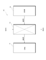
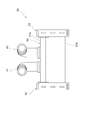
- FIG. 1 is a block diagram showing a schematic configuration of a vehicle intake system.
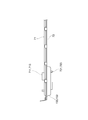
- FIG. 2 is a plan view illustrating a planar structure of the heat exchanger according to the embodiment.
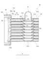
- Drawing 3 is a side view showing the side structure of the heat exchange part of an embodiment.
- FIG. 4 is an enlarged view showing a partially enlarged structure of the side structure of the heat exchange unit of the embodiment.
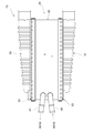
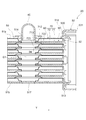
- Drawing 5 is a front view showing the front structure of the heat exchanger of an embodiment.
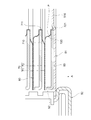
- FIG. 6 is a cross-sectional view showing a part of the cross-sectional structure taken along line VI-VI in FIG.
- FIG. 7 is a cross-sectional view showing a part of the cross-sectional structure along the line VII-VII in FIG.
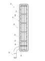
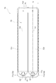
- FIG. 8 is a plan view showing a planar structure of the cooling plate of the embodiment.
- FIG. 9 is an enlarged side view showing a side structure around the cup portion of the cooling plate of the embodiment.
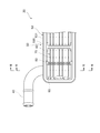
- FIG. 10 is a cross-sectional view illustrating a partial cross-sectional structure of the heat exchange unit of the embodiment.
- FIG. 11 is a plan view showing a planar structure of a cooling plate of a comparative example.
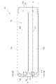
- FIG. 12 is a plan view showing a planar structure of a cooling plate according to another embodiment.
- the intake system 10 is provided with a supercharger 12 that supercharges air taken into the engine 11.
- a supercharger 12 that supercharges air taken into the engine 11.
- a heat exchanger 13 is provided on the downstream side of the intake air flow from the supercharger 12 in the intake system 10. The heat exchanger 13 cools the supercharged air by supplying heat to the engine 11 by performing heat exchange between the air supercharged by the supercharger 12 and the cooling water. Thereby, since the charging efficiency of the air supplied to the engine 11 increases, the output of the engine 11 can be increased.
- the heat exchanger 13 includes a heat exchanging unit 20, tanks 30 and 31, and pipes 40 and 41.
- the heat exchange unit 20 is formed in a substantially rectangular parallelepiped shape.
- the heat exchanging unit 20 includes a duct plate 50, a heat exchanging core unit 60, an inflow side caulking plate 52, and an outflow side caulking plate 53.
- the heat exchange core unit 60 is a part that actually exchanges heat between the supercharged air and the cooling water.
- the duct plate 50 is provided around the heat exchange core part 60 and is a part that introduces supercharged air into the heat exchange core part 60.
- the duct plate 50 is composed of a duct plate upper 51a and a duct plate lower 51b assembled in a cylindrical shape.
- the duct plate 50 is provided so as to surround the heat exchange core part 60. That is, the heat exchange core part 60 is accommodated in the duct plate 50.
- an inflow side opening 512 is formed on one side of the duct plate 50.
- the inflow side opening 512 is a portion into which supercharged air flows.
- an outflow side opening 513 is formed on the other side of the duct plate 50.
- the outflow side opening 513 is a portion through which supercharged air flows out. That is, in the duct plate 50, the supercharged air flows in the direction from the inflow side opening 512 toward the outflow side opening 513, that is, in the direction indicated by the arrow Y in FIGS.
- the direction indicated by the arrow Y is also referred to as “supercharging air flow direction”.
- a cooling water inlet 514 and a cooling water outlet 515 are formed in the duct plate upper 51a.
- the cooling water inlet 514 is located downstream of the cooling water outlet 515 in the supercharging air flow direction Y.
- the cooling water inflow side pipe 40 is connected to the cooling water inlet 514.
- a cooling water outflow side pipe 41 is connected to the cooling water outlet 515. Cooling water flows into the cooling water inlet 514 through the cooling water inflow side piping 40.
- the cooling water flowing in from the cooling water inlet 514 flows through the heat exchange core unit 60.
- the cooling water that has passed through the heat exchange core section 60 flows to the cooling water outflow side pipe 41 via the cooling water outlet 515.
- the inflow side caulking plate 52 is joined to the periphery of the inflow side flange portion 51c of the duct plate upper 51a and the inflow side opening portion 512 of the duct plate lower 51b by brazing or the like. An inlet is formed.
- the inflow side caulking plate 52 has a tank seal portion 520 and a caulking flange portion 521 in an annular shape with respect to the inflow port, a packing (not shown) is inserted into the tank seal portion 520, and the end portion of the inflow side tank 30 is sealed with the packing.
- the inflow side tank 30 can be fixed to the heat exchanging unit 20.
- the outflow side caulking plate 53 is joined to the peripheral edge of the outflow side flange portion 51d of the duct plate upper 51a and the outflow side opening portion 513 of the duct plate lower 51b by brazing or the like. An outlet is formed.
- the outflow side caulking plate 53 has a tank seal portion 530 and a caulking flange portion 531 in an annular shape with respect to the outflow port, a packing (not shown) is inserted into the tank seal portion 530, and the end portion of the outflow side tank 31 is sealed with the packing. The leakage of the supercharged air side is prevented by caulking, and the outflow side tank 31 can be fixed to the heat exchange unit 20.
- the heat exchange core unit 60 includes a plurality of cooling plates 70, a plurality of outer fins 80, and a plurality of spacer plates 90.
- the heat exchange core unit 60 has a structure in which cooling plates 70 and outer fins 80 are alternately stacked. That is, the outer fin 80 is disposed in a predetermined gap formed between two adjacent cooling plates 70 and 70. A gap in which the outer fin 80 is disposed constitutes a supercharged air passage through which supercharged air flows. 3 and 4, only the both end portions of the outer fin 80 are illustrated for convenience, and the other portions are not illustrated.
- the heat exchange core unit 60 cools the supercharged air by exchanging heat between the cooling water flowing inside the cooling plate 70 and the supercharged air flowing outside the cooling plate 70.
- the stacking direction of the plurality of cooling plates 70 and the plurality of outer fins 80 is also referred to as “vertical direction”.
- the cooling plate 70 is formed in a flat shape.
- the cooling plate 70 includes a pair of plates 71 and 72 joined together. A gap is partially formed between the pair of plates 71 and 72. Due to this gap, as shown in FIG. 8, a cooling water flow path 73 through which the cooling water flows is formed inside the cooling plate 70.
- the plate 71 disposed closer to the pipes 40 and 41 out of the pair of plates 71 and 72 is also referred to as an “upper plate”.
- the plate 72 disposed on the side farther from the pipes 40 and 41 out of the pair of plates 71 and 72 is also referred to as a “lower plate”.
- a through hole 712 is formed in a portion of the upper plate 71 facing the cooling water inlet 514 of the duct plate upper 51a.
- a burring portion 713 that protrudes upward is formed on the inner peripheral portion of the through hole 712.
- a through hole 710 is formed in a portion of the upper plate 71 facing the cooling water outlet 515 of the duct plate upper 51 a.
- a burring portion 711 that protrudes upward is also formed in the inner peripheral portion of the through hole 710.
- an inflow side cup portion 722 that protrudes in a cylindrical shape downward is formed in a portion of the lower plate 72 facing the cooling water inlet 514 of the duct plate upper 51 a.
- the inflow side cup portion 722 is a portion for allowing cooling water to flow into the cooling water flow path 73 of the cooling plate 70.
- a burring portion 723 is formed so as to protrude from the opening portion at the tip of the inflow side cup portion 722.
- an outflow side cup portion 720 protruding downward in a cylindrical shape is formed in a portion of the lower plate 72 facing the cooling water outlet 515 of the duct plate upper 51 a. .
- the outflow side cup portion 720 is a portion that causes the cooling water that has flowed through the cooling water flow path 73 of the cooling plate 70 to flow out. As shown in FIG. 9, a burring portion 721 is formed at the opening portion at the tip of the outflow side cup portion 720 so as to protrude.
- the burring portion 723 provided in the inflow side cup portion 722 among the burring portions is caulked and fixed to the through hole 94 of the spacer plate 90, and the burring portion 713 provided in the through hole 712 of the upper plate 71.
- the cooling water flow paths (through holes 712 and cup portions 722) of the plurality of stacked cooling plates 70 can be coaxially stacked by being inserted into the through holes 94 of the spacer plate 90 described above.
- the distribution space G ⁇ b> 1 is configured by the communication between the through-hole 712 and the inflow side cup portion 722 of each cooling plate 70.
- the distribution space G1 communicates with the cooling water inlet 514 of the duct plate upper 51a and also communicates with the cooling water flow path 73 of each cooling plate 70. That is, the cooling water that has flowed into the heat exchange core 60 from the cooling water inflow side pipe 40 via the cooling water inlet 514 of the duct plate upper 51a is distributed to the cooling water flow paths 73 of the respective cooling plates 70 via the distribution space G1. Is done.
- the burring portion 721 provided in the outflow side cup portion 720 is caulked and fixed to the through hole 93 of the spacer plate 90, and the burring portion 711 provided in the through hole 710 of the upper plate 71.
- the cooling water flow paths (through holes 710 and cup portions 720) of the plurality of stacked cooling plates 70 can be coaxially stacked by being inserted into the through holes 93 of the spacer plate 90 described above.
- the through-hole 710 and the outflow side cup part 720 of each cooling plate 70 are communicated to form a collective space G2.
- the collective space G2 communicates with the cooling water outlet 515 of the duct plate upper 51a and also communicates with the cooling water flow path 73 of each cooling plate 70. That is, the cooling water that has flowed through the cooling water flow path 73 of each cooling plate 70 is once collected in the collecting space G2, and then flows out to the cooling water outflow side pipe 41 through the cooling water outlet 515 of the duct plate upper 51a.
- the spacer plate 90 is formed in a plate shape. At both ends of the spacer plate 90 in the supercharging air flow direction Y, blocking walls 92 are formed so as to be folded upward.
- the outer fin 80 is not disposed at the portion where the blocking wall 92 is disposed.
- the blocking wall 92 increases the cooling efficiency of the supercharged air by preventing the supercharged air from flowing into the portion where the outer fin 80 is not disposed.
- the through holes 93 and 94 of the spacer plate 90 arranged at the bottom are closed when the projecting portions 516 and 517 formed in the duct plate lower 51b are fitted.
- the cooling water flow path 73 formed inside the cooling plate 70 includes a first flow path portion 730, a second flow path portion 731, and a U-turn portion 732.
- the first flow path portion 730 is formed so as to extend from one end portion 74 where the through hole 712 and the inflow side cup portion 722 in the cooling plate 70 are formed toward the other end portion 75.
- the first flow path portion 730 is in communication with the distribution space G ⁇ b> 1 through the through hole 712 and the inflow side cup portion 722.
- the second flow path portion 731 is formed so as to extend from one end portion 74 where the through hole 710 and the outflow side cup portion 720 in the cooling plate 70 are formed toward the other end portion 75.
- the second flow path portion 731 is communicated with the collective space G ⁇ b> 2 via the through hole 710 and the outflow side cup portion 720.
- the first flow path portion 730 and the second flow path portion 731 are formed to extend in a direction orthogonal to the supercharging air flow direction Y.
- the first flow path portion 730 and the second flow path portion 731 are communicated with each other by a U-turn portion 732 at the other end portion 75 of the cooling plate 70.
- the U-turn portion 732 is formed to be bent in a U shape.
- the cooling water flows from the distribution space G 1 into the first flow path portion 730, and this cooling water flows through the U-turn portion 732 to the second flow. It flows to the road portion 731.
- the cooling water that has flowed through the second flow path portion 731 flows into the collective space G2.
- the axes m1 and m2 in the figure are the flow of the first flow path part 730.
- the center in the channel width direction H and the center in the channel width direction H of the second channel portion 731 are shown. Therefore, the through hole 712 and the inflow side cup portion 722 are arranged at positions shifted to the upstream side in the supercharging air flow direction from the center m1 of the first flow path portion 730. Further, the through-hole 710 and the outflow side cup portion 720 are arranged at positions shifted to the downstream side in the supercharging air flow direction Y from the center m2 of the second flow path portion 731.
- the supercharged air passes from the inflow side tank 30 through the inflow side of the inflow side caulking plate 52 to the inside of the duct plate 50 constituted by the duct plate upper 51a and the duct plate lower 51b. be introduced.
- the supercharged air passes through the gap between the cooling plates 70, that is, the heat exchange core portion 60 where the outer fin 80 is disposed, and flows to the outflow side tank 31.
- the cooling water flows into the heat exchange core section 60 through the cooling water inflow side pipe 40.
- the cooling water that has flowed into the heat exchange core portion 60 from the cooling water inflow side pipe 40 is distributed to the cooling water flow paths 73 of the respective cooling plates 70 via the distribution space G1.
- the cooling water distributed to the cooling water flow path 73 of each cooling plate 70 flows in order through the first flow path portion 730, the U-turn portion 732, and the second flow path portion 731 and is collected in the collective space G2.
- the supercharged air flows in the direction indicated by the arrow Y outside the cooling plate 70.
- the cooling water flows through the first flow path portion 730, the U-turn portion 732, and the second flow path portion 731, the supercharged air is cooled by absorbing the heat of the supercharged air.
- the cooling water collected in the gathering space G2 is discharged to the outside through the cooling water outflow side pipe 41.
- the duct plate 50 and the caulking plates 52 and 53 are likely to be deformed due to the heat of the supercharged air and the internal pressure.
- the inflow side caulking plate 52, the duct plate upper 51a, and the duct plate lower 51b which have a high supercharged air temperature, are easily deformed, and the inflow side caulking plate 52 is in the direction indicated by the arrow A as shown in FIG. Since the duct plate 50 and the spacer plate 90 are pulled due to the deformation of the inflow side caulking plate 52 due to the structure, excessive distortion occurs in the portion P of the outflow side cup portion 720 of the cooling plate 70 joined thereto. .
- the inflow side cup portion 722 of the cooling plate 70 may be distorted in the same manner.
- the supercharger temperature is lower than that of the inflow side, the generated distortion also occurs. There is a tendency to become smaller.
- the outflow side cup portion 720 is shifted to the downstream side in the supercharging air flow direction from the center m2 of the second flow path portion 731. It is formed in a cylindrical shape so as to have a central axis at a certain position. Accordingly, as shown in FIG. 11, the outflow side cup portion of the present embodiment is compared with the case where the outflow side cup portion 720 is formed so as to have a central axis at the center m2 of the second flow path portion 731. 720 is disposed away from the inflow side caulking plate 52.
- the outflow side cup portion 720 is formed in a cylindrical shape so as to have a central axis at a position shifted to the downstream side in the supercharging air flow direction from the center m2 of the second flow path portion 731.
- the inflow side cup portion 722 is formed in a cylindrical shape so as to have a central axis at a position shifted from the center m1 of the first flow path portion 730 to the upstream side in the flow direction of the supercharged air.
- the heat exchange section 20 includes the heat exchange core section 60, the duct plate 50, the inflow side caulking plate 52, and the outflow side caulking plate 53, and the cooling plate 70 and the duct plate 50 are joined. And the inflow side caulking plate 52 and the outflow side caulking plate 53, the inflow side caulking plate 52 and the outflow side caulking plate 53 are likely to be deformed by the heat of the supercharged air. This is a factor that tends to cause distortion in the cup portions 720 and 722 due to the structure of the heat exchanger 13. Therefore, the structure in which the cup portions 720 and 722 are arranged as in the present embodiment is particularly effective.
- the heat exchanger 13 further includes a spacer plate 90 joined to the duct plate lower 51 b and the cooling plate 70, and the spacer plate 90 prevents the supercharged air from flowing outside the outer fin 80.
- a spacer plate 90 is provided in the heat exchanger 13 when the inflow side caulking plate 52 and the outflow side caulking plate 53 are deformed due to the heat of the supercharged air, the cup portions 720 and 722 are deformed. Distortion is likely to occur. Therefore, the structure in which the cup portions 720 and 722 are arranged as in the present embodiment is particularly effective.
- the said embodiment can also be implemented with the following forms.
- the position of the inflow side cup portion 722 may be a position along the center m1 of the first flow path portion 730 in the flow path width direction. Even if it is such a structure, the effect
- the shape of the cooling water flow path 73 of the cooling plate 70 is not limited to the U shape, and can be changed as appropriate.
- the shape of the cooling water channel 73 may be, for example, a linear shape.
- an inflow side cup portion is disposed at one end thereof, and an outflow side cup portion is disposed at the other end portion.
- the inflow side cup portion and the outflow side cup portion may be formed in a cylindrical shape so as to have a central axis at a position shifted to the downstream side in the supercharging air flow direction from the center of the flow path portion. .
- the heat exchanger 13 may have a structure that does not have the spacer plate 90. In the heat exchanger 13 having such a structure, even if the cup parts 720 and 722 of the cooling plate 70 arranged at the lowermost stage are joined to the duct plate 50, the cup parts 720 and 722 are connected as in the above embodiment. If it arrange
- the shape of the cup portions 720 and 722 is not limited to a cylindrical shape, and can be changed to an arbitrary cylindrical shape such as a square cylindrical shape. -This indication is not limited to said specific example. Any of the above specific examples that are appropriately modified by those skilled in the art are also included in the scope of the present disclosure as long as they have the features of the present disclosure. Each element included in each of the specific examples described above, and the arrangement, conditions, shape, and the like thereof are not limited to those illustrated, and can be appropriately changed. Each element included in each of the specific examples described above can be appropriately combined as long as no technical contradiction occurs.
Abstract
This heat exchanger is provided with: a plurality of cooling plates (70); and a duct plate disposed around the cooling plates. The cooling plates have cup parts (720, 722) that are joined to cooling plates that are adjacent to each other to communicate respective cooling water flow paths of the two cooling plates. The cooling water flow paths formed in the cooling plates have flow path parts (730, 731) that are formed to extend in a direction perpendicular to the flow direction of a supercharger from the cup parts. The cup parts are each formed in a cylindrical shape so as to have a center axis at a position that is offset, in the flow direction of the supercharger, from the center in the flow path width direction of the flow path part.
Description
本出願は、2017年2月21日に出願された日本国特許出願2017-030093号に基づくものであって、その優先権の利益を主張するものであり、その特許出願の全ての内容が、参照により本明細書に組み込まれる。
This application is based on Japanese Patent Application No. 2017-030093 filed on Feb. 21, 2017, and claims the benefit of its priority. Which is incorporated herein by reference.
本開示は、車両の過給気を冷却する熱交換器に関する。
The present disclosure relates to a heat exchanger that cools supercharged air of a vehicle.
従来、この種の熱交換器としては、特許文献1に記載の熱交換器がある。特許文献1に記載の熱交換器は、積層された複数のプレートと、プレートを囲むように配置されるハウジングとを備えている。隣り合うプレート間の隙間により、冷却流体の流れる冷却流体流路が構成されている。すなわち、特許文献1に記載の熱交換器では、プレートの積層方向に沿って複数の冷却流体流路が積層して配置されている。各冷却流体流路は、複数のプレートのそれぞれに形成される筒状のカップ部を介して互いに連通されている。特許文献1に記載の熱交換器では、プレート間を流れる冷却流体と、車両の過給気との間で熱交換が行われることにより、過給気が冷却される。
Conventionally, as this type of heat exchanger, there is a heat exchanger described in Patent Document 1. The heat exchanger described in Patent Document 1 includes a plurality of stacked plates and a housing arranged so as to surround the plates. A cooling fluid flow path through which a cooling fluid flows is formed by a gap between adjacent plates. That is, in the heat exchanger described in Patent Document 1, a plurality of cooling fluid flow paths are stacked and arranged along the stacking direction of the plates. Each cooling fluid flow path is communicated with each other via a cylindrical cup portion formed in each of the plurality of plates. In the heat exchanger described in Patent Document 1, the supercharged air is cooled by performing heat exchange between the cooling fluid flowing between the plates and the supercharged air of the vehicle.
特許文献1に記載の熱交換器では、プレートのカップ部とハウジングとが接触して、あるいは互いに近接して配置される可能性がある。一方、ハウジングは、過給気の熱により加熱されることで変形する可能性がある。ハウジングの変形によりプレートのカップ部にハウジングが接触すると、プレートのカップ部に歪みが生じる。これが、カップ部の耐久性を悪化させる要因となっている。
In the heat exchanger described in Patent Document 1, there is a possibility that the cup portion of the plate and the housing are in contact with each other or close to each other. On the other hand, the housing may be deformed by being heated by the heat of the supercharged air. When the housing contacts the cup portion of the plate due to deformation of the housing, the plate cup portion is distorted. This is a factor that deteriorates the durability of the cup portion.
本開示の目的は、カップ部の耐久性を向上させることの可能な熱交換器を提供することにある。
An object of the present disclosure is to provide a heat exchanger capable of improving the durability of the cup portion.
本開示の一態様による熱交換器は、複数の冷却プレートと、ダクトプレートと、を備える。複数の冷却プレートは、冷却水の流れる冷却水流路を有し、所定の隙間を有して積層して配置される。ダクトプレートは、積層された複数の冷却プレートの周囲に設けられ、過給気が流入する流入側開口部、及び過給気が流出する流出側開口部を有する。冷却プレートは、隣り合う冷却プレートに接合されることにより2つの冷却プレートのそれぞれの冷却水流路を連通させるカップ部を有する。冷却水流路は、カップ部から過給気の流れ方向に直交する方向に延びるように形成される流路部分を有する。カップ部は、流路部分における冷却水の流れ方向に直交する方向を流路幅方向とするとき、流路部分の流路幅方向の中心よりも過給気の流れ方向にずれた位置に中心軸を有するように筒状に形成されている。
The heat exchanger according to an aspect of the present disclosure includes a plurality of cooling plates and a duct plate. The plurality of cooling plates have a cooling water flow path through which the cooling water flows, and are stacked with a predetermined gap. The duct plate is provided around a plurality of stacked cooling plates, and has an inflow side opening through which the supercharged air flows and an outflow side opening through which the supercharged air flows out. A cooling plate has a cup part which connects each cooling water flow path of two cooling plates by joining to an adjacent cooling plate. The cooling water channel has a channel part formed so as to extend from the cup part in a direction orthogonal to the flow direction of the supercharged air. The cup portion is centered at a position shifted in the supercharging air flow direction from the center of the flow passage portion in the flow passage width direction when the direction perpendicular to the flow direction of the cooling water in the flow passage portion is defined as the flow passage width direction. It is formed in a cylindrical shape so as to have an axis.
この構成によれば、流路部分の流路幅方向の中心に沿って中心軸を有するようにカップ部が形成されている場合と比較すると、上記構成のカップ部の方が、ダクトプレートの流入側開口部あるいは流出側開口部から離間して配置されることになる。したがって、仮に過給気の熱によりダクトプレートの流入側開口部あるいは流出側開口部の部位が変形した場合でも、カップ部に歪みが生じ難くなる。よって、カップ部の耐久性を向上させることができる。
According to this configuration, compared to the case where the cup portion is formed so as to have the central axis along the center of the flow passage width direction of the flow passage portion, the cup portion configured as described above is more inflow of the duct plate. It is arranged to be separated from the side opening or the outflow side opening. Therefore, even if the inflow side opening portion or the outflow side opening portion of the duct plate is deformed due to the heat of the supercharged air, the cup portion is less likely to be distorted. Therefore, the durability of the cup portion can be improved.
以下、熱交換器の一実施形態について図面を参照しながら説明する。説明の理解を容易にするため、各図面において同一の構成要素に対しては可能な限り同一の符号を付して、重複する説明は省略する。はじめに、本実施形態の熱交換器が設けられる車両の吸気系の概要について説明する。
Hereinafter, an embodiment of a heat exchanger will be described with reference to the drawings. In order to facilitate the understanding of the description, the same constituent elements in the drawings will be denoted by the same reference numerals as much as possible, and redundant description will be omitted. First, an outline of an intake system of a vehicle provided with the heat exchanger of the present embodiment will be described.
図1に示されるように、吸気系10には、エンジン11に吸入される空気を過給する過給機12が設けられている。過給気をエンジン11に吸入させることにより、エンジン11の最高出力を補うことができる。
吸気系10における過給機12よりも吸気流れ下流側には、熱交換器13が設けられている。熱交換器13は、過給機12により過給された空気と冷却水との間で熱交換を行うことにより、過給気を冷却してエンジン11に供給する。これにより、エンジン11に供給される空気の充填効率が高まるため、エンジン11の出力を高めることができる。 As shown in FIG. 1, theintake system 10 is provided with a supercharger 12 that supercharges air taken into the engine 11. By causing the engine 11 to inhale the supercharged air, the maximum output of the engine 11 can be supplemented.
Aheat exchanger 13 is provided on the downstream side of the intake air flow from the supercharger 12 in the intake system 10. The heat exchanger 13 cools the supercharged air by supplying heat to the engine 11 by performing heat exchange between the air supercharged by the supercharger 12 and the cooling water. Thereby, since the charging efficiency of the air supplied to the engine 11 increases, the output of the engine 11 can be increased.
吸気系10における過給機12よりも吸気流れ下流側には、熱交換器13が設けられている。熱交換器13は、過給機12により過給された空気と冷却水との間で熱交換を行うことにより、過給気を冷却してエンジン11に供給する。これにより、エンジン11に供給される空気の充填効率が高まるため、エンジン11の出力を高めることができる。 As shown in FIG. 1, the
A
次に、熱交換器13の構造について具体的に説明する。
図2に示されるように、熱交換器13は、熱交換部20と、タンク30,31と、配管40,41とを備えている。
図3~図5に示されるように、熱交換部20は、略直方体状に形成されている。熱交換部20は、ダクトプレート50と、熱交換コア部60と、流入側かしめプレート52と、流出側かしめプレート53とを有している。熱交換コア部60は、過給気と冷却水との間で実際に熱交換を行う部分である。ダクトプレート50は、熱交換コア部60の周囲に設けられており、熱交換コア部60に過給気に導入する部分である。 Next, the structure of theheat exchanger 13 will be specifically described.
As shown in FIG. 2, theheat exchanger 13 includes a heat exchanging unit 20, tanks 30 and 31, and pipes 40 and 41.
As shown in FIGS. 3 to 5, theheat exchange unit 20 is formed in a substantially rectangular parallelepiped shape. The heat exchanging unit 20 includes a duct plate 50, a heat exchanging core unit 60, an inflow side caulking plate 52, and an outflow side caulking plate 53. The heat exchange core unit 60 is a part that actually exchanges heat between the supercharged air and the cooling water. The duct plate 50 is provided around the heat exchange core part 60 and is a part that introduces supercharged air into the heat exchange core part 60.
図2に示されるように、熱交換器13は、熱交換部20と、タンク30,31と、配管40,41とを備えている。
図3~図5に示されるように、熱交換部20は、略直方体状に形成されている。熱交換部20は、ダクトプレート50と、熱交換コア部60と、流入側かしめプレート52と、流出側かしめプレート53とを有している。熱交換コア部60は、過給気と冷却水との間で実際に熱交換を行う部分である。ダクトプレート50は、熱交換コア部60の周囲に設けられており、熱交換コア部60に過給気に導入する部分である。 Next, the structure of the
As shown in FIG. 2, the
As shown in FIGS. 3 to 5, the
図5に示されるように、ダクトプレート50は、筒状に組み付けられたダクトプレートアッパ51a及びダクトプレートロア51bにより構成されている。ダクトプレート50は、熱交換コア部60を囲繞するように設けられている。すなわち、熱交換コア部60は、ダクトプレート50の内部に収容されている。
As shown in FIG. 5, the duct plate 50 is composed of a duct plate upper 51a and a duct plate lower 51b assembled in a cylindrical shape. The duct plate 50 is provided so as to surround the heat exchange core part 60. That is, the heat exchange core part 60 is accommodated in the duct plate 50.
図6に示されるように、ダクトプレート50の一側部には、流入側開口部512が形成されている。流入側開口部512は、過給気が流入する部分である。図7に示されるように、ダクトプレート50の他側部には、流出側開口部513が形成されている。流出側開口部513は、過給気が流出する部分である。すなわち、ダクトプレート50では、流入側開口部512から流出側開口部513に向かう方向、すなわち図6及び図7の矢印Yで示される方向に過給気が流れる。以下では、矢印Yで示される方向を「過給気の流れ方向」とも称する。
As shown in FIG. 6, an inflow side opening 512 is formed on one side of the duct plate 50. The inflow side opening 512 is a portion into which supercharged air flows. As shown in FIG. 7, an outflow side opening 513 is formed on the other side of the duct plate 50. The outflow side opening 513 is a portion through which supercharged air flows out. That is, in the duct plate 50, the supercharged air flows in the direction from the inflow side opening 512 toward the outflow side opening 513, that is, in the direction indicated by the arrow Y in FIGS. Hereinafter, the direction indicated by the arrow Y is also referred to as “supercharging air flow direction”.
図6及び図7に示されるように、ダクトプレートアッパ51aには、冷却水流入口514及び冷却水流出口515が形成されている。冷却水流入口514は、冷却水流出口515に対して過給気の流れ方向Yの下流側に位置している。冷却水流入口514には、冷却水流入側配管40が接続されている。冷却水流出口515には、冷却水流出側配管41が接続されている。冷却水流入口514には、冷却水流入側配管40を介して冷却水が流入する。冷却水流入口514から流入した冷却水は、熱交換コア部60を流れる。熱交換コア部60を通過した冷却水は、冷却水流出口515を介して冷却水流出側配管41へと流れる。
6 and 7, a cooling water inlet 514 and a cooling water outlet 515 are formed in the duct plate upper 51a. The cooling water inlet 514 is located downstream of the cooling water outlet 515 in the supercharging air flow direction Y. The cooling water inflow side pipe 40 is connected to the cooling water inlet 514. A cooling water outflow side pipe 41 is connected to the cooling water outlet 515. Cooling water flows into the cooling water inlet 514 through the cooling water inflow side piping 40. The cooling water flowing in from the cooling water inlet 514 flows through the heat exchange core unit 60. The cooling water that has passed through the heat exchange core section 60 flows to the cooling water outflow side pipe 41 via the cooling water outlet 515.
図6に示されるように、流入側かしめプレート52は、ダクトプレートアッパ51aの流入側フランジ部51cとダクトプレートロア51bの流入側開口部512の周縁にろう付け等により接合され、過給気の流入口を形成している。流入側かしめプレート52は、タンクシール部520と、かしめ用フランジ部521とを流入口に対し環状に有し、図示しないパッキンをタンクシール部520に挿入し、流入側タンク30の端部をパッキンを挟んでかしめることで過給気側の漏れを防止するとともに、熱交換部20への流入側タンク30の固定を可能にしている。
As shown in FIG. 6, the inflow side caulking plate 52 is joined to the periphery of the inflow side flange portion 51c of the duct plate upper 51a and the inflow side opening portion 512 of the duct plate lower 51b by brazing or the like. An inlet is formed. The inflow side caulking plate 52 has a tank seal portion 520 and a caulking flange portion 521 in an annular shape with respect to the inflow port, a packing (not shown) is inserted into the tank seal portion 520, and the end portion of the inflow side tank 30 is sealed with the packing. In addition to preventing leakage on the supercharger side, the inflow side tank 30 can be fixed to the heat exchanging unit 20.
図7に示されるように、流出側かしめプレート53は、ダクトプレートアッパ51aの流出側フランジ部51dとダクトプレートロア51bの流出側開口部513の周縁にろう付け等により接合され、過給気の流出口を形成している。流出側かしめプレート53は、タンクシール部530と、かしめ用フランジ部531とを流出口に対し環状に有し、図示しないパッキンをタンクシール部530に挿入し、流出側タンク31の端部をパッキンを挟んでかしめることで過給気側の漏れを防止するとともに、熱交換部20への流出側タンク31の固定を可能にしている。
As shown in FIG. 7, the outflow side caulking plate 53 is joined to the peripheral edge of the outflow side flange portion 51d of the duct plate upper 51a and the outflow side opening portion 513 of the duct plate lower 51b by brazing or the like. An outlet is formed. The outflow side caulking plate 53 has a tank seal portion 530 and a caulking flange portion 531 in an annular shape with respect to the outflow port, a packing (not shown) is inserted into the tank seal portion 530, and the end portion of the outflow side tank 31 is sealed with the packing. The leakage of the supercharged air side is prevented by caulking, and the outflow side tank 31 can be fixed to the heat exchange unit 20.
図3及び図4に示されるように、熱交換コア部60は、複数の冷却プレート70と、複数のアウタフィン80と、複数のスペーサプレート90とを有している。
熱交換コア部60は、冷却プレート70とアウタフィン80とが交互に積層された構造を有している。すなわち、アウタフィン80は、隣り合う2つの冷却プレート70,70の間に形成される所定の隙間に配置されている。アウタフィン80が配置される隙間は、過給気の流れる過給気流路を構成している。なお、図3及び図4では、便宜上、アウタフィン80の両端部のみが図示されており、その他の部分の図示が省略されている。熱交換コア部60は、冷却プレート70の内部を流れる冷却水と、冷却プレート70の外部を流れる過給気との間で熱交換を行うことにより、過給気を冷却する。以下では、便宜上、複数の冷却プレート70及び複数のアウタフィン80の積層方向を「上下方向」とも称する。 As shown in FIGS. 3 and 4, the heatexchange core unit 60 includes a plurality of cooling plates 70, a plurality of outer fins 80, and a plurality of spacer plates 90.
The heatexchange core unit 60 has a structure in which cooling plates 70 and outer fins 80 are alternately stacked. That is, the outer fin 80 is disposed in a predetermined gap formed between two adjacent cooling plates 70 and 70. A gap in which the outer fin 80 is disposed constitutes a supercharged air passage through which supercharged air flows. 3 and 4, only the both end portions of the outer fin 80 are illustrated for convenience, and the other portions are not illustrated. The heat exchange core unit 60 cools the supercharged air by exchanging heat between the cooling water flowing inside the cooling plate 70 and the supercharged air flowing outside the cooling plate 70. Hereinafter, for convenience, the stacking direction of the plurality of cooling plates 70 and the plurality of outer fins 80 is also referred to as “vertical direction”.
熱交換コア部60は、冷却プレート70とアウタフィン80とが交互に積層された構造を有している。すなわち、アウタフィン80は、隣り合う2つの冷却プレート70,70の間に形成される所定の隙間に配置されている。アウタフィン80が配置される隙間は、過給気の流れる過給気流路を構成している。なお、図3及び図4では、便宜上、アウタフィン80の両端部のみが図示されており、その他の部分の図示が省略されている。熱交換コア部60は、冷却プレート70の内部を流れる冷却水と、冷却プレート70の外部を流れる過給気との間で熱交換を行うことにより、過給気を冷却する。以下では、便宜上、複数の冷却プレート70及び複数のアウタフィン80の積層方向を「上下方向」とも称する。 As shown in FIGS. 3 and 4, the heat
The heat
図6及び図7に示されるように、冷却プレート70は、扁平状に形成されている。冷却プレート70は、互いに接合された一対のプレート71,72からなる。一対のプレート71,72の間には部分的に隙間が形成されている。この隙間により、図8に示されるように、冷却プレート70の内部に、冷却水の流れる冷却水流路73が形成されている。以下では、便宜上、一対のプレート71,72のうち、より配管40,41に近い側に配置されるプレート71を「上側プレート」とも称する。また、一対のプレート71,72のうち、より配管40,41から遠い側に配置されるプレート72を「下側プレート」とも称する。
As shown in FIGS. 6 and 7, the cooling plate 70 is formed in a flat shape. The cooling plate 70 includes a pair of plates 71 and 72 joined together. A gap is partially formed between the pair of plates 71 and 72. Due to this gap, as shown in FIG. 8, a cooling water flow path 73 through which the cooling water flows is formed inside the cooling plate 70. Hereinafter, for convenience, the plate 71 disposed closer to the pipes 40 and 41 out of the pair of plates 71 and 72 is also referred to as an “upper plate”. In addition, the plate 72 disposed on the side farther from the pipes 40 and 41 out of the pair of plates 71 and 72 is also referred to as a “lower plate”.
図7に示されるように、上側プレート71におけるダクトプレートアッパ51aの冷却水流入口514に対向する部分には、貫通孔712が形成されている。貫通孔712の内周部分には、図9に示されるように、上方に向かって突出するバーリング部713が形成されている。また、図6に示されるように、上側プレート71におけるダクトプレートアッパ51aの冷却水流出口515に対向する部分には、貫通孔710が形成されている。貫通孔710の内周部分にも、図9に示されるように、上方に向かって突出するバーリング部711が形成されている。
7, a through hole 712 is formed in a portion of the upper plate 71 facing the cooling water inlet 514 of the duct plate upper 51a. As shown in FIG. 9, a burring portion 713 that protrudes upward is formed on the inner peripheral portion of the through hole 712. Further, as shown in FIG. 6, a through hole 710 is formed in a portion of the upper plate 71 facing the cooling water outlet 515 of the duct plate upper 51 a. As shown in FIG. 9, a burring portion 711 that protrudes upward is also formed in the inner peripheral portion of the through hole 710.
図7に示されるように、下側プレート72におけるダクトプレートアッパ51aの冷却水流入口514に対向する部分には、下方に向かって円筒状に突出する流入側カップ部722が形成されている。流入側カップ部722は、冷却プレート70の冷却水流路73に冷却水を流入させる部分である。図9に示されるように、流入側カップ部722の先端の開口部分には、バーリング部723が突出するように形成されている。また、図6に示されるように、下側プレート72におけるダクトプレートアッパ51aの冷却水流出口515に対向する部分には、下方に向かって円筒状に突出する流出側カップ部720が形成されている。流出側カップ部720は、冷却プレート70の冷却水流路73を流れた冷却水を流出させる部分である。流出側カップ部720の先端の開口部分には、図9に示されるように、バーリング部721が突出するように形成されている。
As shown in FIG. 7, an inflow side cup portion 722 that protrudes in a cylindrical shape downward is formed in a portion of the lower plate 72 facing the cooling water inlet 514 of the duct plate upper 51 a. The inflow side cup portion 722 is a portion for allowing cooling water to flow into the cooling water flow path 73 of the cooling plate 70. As shown in FIG. 9, a burring portion 723 is formed so as to protrude from the opening portion at the tip of the inflow side cup portion 722. Further, as shown in FIG. 6, an outflow side cup portion 720 protruding downward in a cylindrical shape is formed in a portion of the lower plate 72 facing the cooling water outlet 515 of the duct plate upper 51 a. . The outflow side cup portion 720 is a portion that causes the cooling water that has flowed through the cooling water flow path 73 of the cooling plate 70 to flow out. As shown in FIG. 9, a burring portion 721 is formed at the opening portion at the tip of the outflow side cup portion 720 so as to protrude.
図7に示されるように、バーリング部のうち、流入側カップ部722に設けられるバーリング部723はスペーサプレート90の貫通孔94にかしめ固定され、上側プレート71の貫通孔712に設けられるバーリング部713も前述のスペーサプレート90の貫通孔94に挿入されることで、積層された複数の冷却プレート70の冷却水流路(貫通孔712,カップ部722)同士を同軸に積層することができる。
As shown in FIG. 7, the burring portion 723 provided in the inflow side cup portion 722 among the burring portions is caulked and fixed to the through hole 94 of the spacer plate 90, and the burring portion 713 provided in the through hole 712 of the upper plate 71. In addition, the cooling water flow paths (through holes 712 and cup portions 722) of the plurality of stacked cooling plates 70 can be coaxially stacked by being inserted into the through holes 94 of the spacer plate 90 described above.
各冷却プレート70の貫通孔712及び流入側カップ部722が連通されることにより、分配空間G1が構成されている。分配空間G1は、ダクトプレートアッパ51aの冷却水流入口514に連通されるとともに、各冷却プレート70の冷却水流路73に連通されている。すなわち、冷却水流入側配管40からダクトプレートアッパ51aの冷却水流入口514を介して熱交換コア部60に流入した冷却水は、分配空間G1を介して各冷却プレート70の冷却水流路73に分配される。
The distribution space G <b> 1 is configured by the communication between the through-hole 712 and the inflow side cup portion 722 of each cooling plate 70. The distribution space G1 communicates with the cooling water inlet 514 of the duct plate upper 51a and also communicates with the cooling water flow path 73 of each cooling plate 70. That is, the cooling water that has flowed into the heat exchange core 60 from the cooling water inflow side pipe 40 via the cooling water inlet 514 of the duct plate upper 51a is distributed to the cooling water flow paths 73 of the respective cooling plates 70 via the distribution space G1. Is done.
図6に示されるように、バーリング部のうち、流出側カップ部720に設けられるバーリング部721はスペーサプレート90の貫通孔93にかしめ固定され、上側プレート71の貫通孔710に設けられるバーリング部711も前述のスペーサプレート90の貫通孔93に挿入されることで、積層された複数の冷却プレート70の冷却水流路(貫通孔710,カップ部720)同士を同軸に積層することができる。
As shown in FIG. 6, among the burring portions, the burring portion 721 provided in the outflow side cup portion 720 is caulked and fixed to the through hole 93 of the spacer plate 90, and the burring portion 711 provided in the through hole 710 of the upper plate 71. Also, the cooling water flow paths (through holes 710 and cup portions 720) of the plurality of stacked cooling plates 70 can be coaxially stacked by being inserted into the through holes 93 of the spacer plate 90 described above.
各冷却プレート70の貫通孔710及び流出側カップ部720が連通されることにより、集合空間G2が構成されている。集合空間G2は、ダクトプレートアッパ51aの冷却水流出口515に連通されるとともに、各冷却プレート70の冷却水流路73に連通されている。すなわち、各冷却プレート70の冷却水流路73を流れた冷却水は集合空間G2で一旦集められた後、ダクトプレートアッパ51aの冷却水流出口515を介して冷却水流出側配管41に流出する。
The through-hole 710 and the outflow side cup part 720 of each cooling plate 70 are communicated to form a collective space G2. The collective space G2 communicates with the cooling water outlet 515 of the duct plate upper 51a and also communicates with the cooling water flow path 73 of each cooling plate 70. That is, the cooling water that has flowed through the cooling water flow path 73 of each cooling plate 70 is once collected in the collecting space G2, and then flows out to the cooling water outflow side pipe 41 through the cooling water outlet 515 of the duct plate upper 51a.
図6及び図7に示されるように、スペーサプレート90は、板状に形成されている。過給気の流れ方向Yにおけるスペーサプレート90の両端部には、上方に向かって折りまげられるように遮断壁92が形成されている。遮断壁92が配置されている部分には、アウタフィン80が配置されていない。遮断壁92は、アウタフィン80の配置されていない部分への過給気の流入を妨げることにより、過給気の冷却効率を高めている。
As shown in FIGS. 6 and 7, the spacer plate 90 is formed in a plate shape. At both ends of the spacer plate 90 in the supercharging air flow direction Y, blocking walls 92 are formed so as to be folded upward. The outer fin 80 is not disposed at the portion where the blocking wall 92 is disposed. The blocking wall 92 increases the cooling efficiency of the supercharged air by preventing the supercharged air from flowing into the portion where the outer fin 80 is not disposed.
なお、図6及び図7に示されるように、最下段に配置されるスペーサプレート90の貫通孔93,94は、ダクトプレートロア51bに形成された突出部516,517が嵌合することにより閉塞されている。
図8に示されるように、冷却プレート70の内部に形成される冷却水流路73は、第1流路部分730と、第2流路部分731と、Uターン部732とを有している。 As shown in FIGS. 6 and 7, the through holes 93 and 94 of the spacer plate 90 arranged at the bottom are closed when the projecting portions 516 and 517 formed in the duct plate lower 51b are fitted. Has been.
As shown in FIG. 8, the coolingwater flow path 73 formed inside the cooling plate 70 includes a first flow path portion 730, a second flow path portion 731, and a U-turn portion 732.
図8に示されるように、冷却プレート70の内部に形成される冷却水流路73は、第1流路部分730と、第2流路部分731と、Uターン部732とを有している。 As shown in FIGS. 6 and 7, the through
As shown in FIG. 8, the cooling
第1流路部分730は、冷却プレート70における貫通孔712及び流入側カップ部722が形成されている一端部74から他端部75に向かって延びるように形成されている。第1流路部分730は、貫通孔712及び流入側カップ部722を介して分配空間G1に連通されている。第2流路部分731は、冷却プレート70における貫通孔710及び流出側カップ部720が形成されている一端部74から他端部75に向かって延びるように形成されている。第2流路部分731は、貫通孔710及び流出側カップ部720を介して集合空間G2に連通されている。第1流路部分730及び第2流路部分731は、過給気の流れ方向Yに直交する方向に延びるように形成されている。
The first flow path portion 730 is formed so as to extend from one end portion 74 where the through hole 712 and the inflow side cup portion 722 in the cooling plate 70 are formed toward the other end portion 75. The first flow path portion 730 is in communication with the distribution space G <b> 1 through the through hole 712 and the inflow side cup portion 722. The second flow path portion 731 is formed so as to extend from one end portion 74 where the through hole 710 and the outflow side cup portion 720 in the cooling plate 70 are formed toward the other end portion 75. The second flow path portion 731 is communicated with the collective space G <b> 2 via the through hole 710 and the outflow side cup portion 720. The first flow path portion 730 and the second flow path portion 731 are formed to extend in a direction orthogonal to the supercharging air flow direction Y.
第1流路部分730及び第2流路部分731は、冷却プレート70の他端部75においてUターン部732により連通されている。Uターン部732は、U字状に屈曲するように形成されている。
この冷却プレート70では、図中に破線の矢印で示されるように、分配空間G1から第1流路部分730に冷却水が流入するとともに、この冷却水がUターン部732を介して第2流路部分731へと流れる。第2流路部分731を流れた冷却水は、集合空間G2へと流れる。 The firstflow path portion 730 and the second flow path portion 731 are communicated with each other by a U-turn portion 732 at the other end portion 75 of the cooling plate 70. The U-turn portion 732 is formed to be bent in a U shape.
In thecooling plate 70, as indicated by the dashed arrows in the drawing, the cooling water flows from the distribution space G 1 into the first flow path portion 730, and this cooling water flows through the U-turn portion 732 to the second flow. It flows to the road portion 731. The cooling water that has flowed through the second flow path portion 731 flows into the collective space G2.
この冷却プレート70では、図中に破線の矢印で示されるように、分配空間G1から第1流路部分730に冷却水が流入するとともに、この冷却水がUターン部732を介して第2流路部分731へと流れる。第2流路部分731を流れた冷却水は、集合空間G2へと流れる。 The first
In the
第1流路部分730及び第2流路部分731における冷却水の流れ方向に直交する方向を流路幅方向Hとするとき、図中の軸線m1,m2は、第1流路部分730の流路幅方向Hの中心、及び第2流路部分731の流路幅方向Hの中心をそれぞれ示している。したがって、貫通孔712及び流入側カップ部722は、第1流路部分730の中心m1よりも過給気の流れ方向の上流側にずれた位置に配置されている。また、貫通孔710及び流出側カップ部720は、第2流路部分731の中心m2よりも過給気の流れ方向Yの下流側にずれた位置に配置されている。
When the direction orthogonal to the flow direction of the cooling water in the first flow path part 730 and the second flow path part 731 is a flow path width direction H, the axes m1 and m2 in the figure are the flow of the first flow path part 730. The center in the channel width direction H and the center in the channel width direction H of the second channel portion 731 are shown. Therefore, the through hole 712 and the inflow side cup portion 722 are arranged at positions shifted to the upstream side in the supercharging air flow direction from the center m1 of the first flow path portion 730. Further, the through-hole 710 and the outflow side cup portion 720 are arranged at positions shifted to the downstream side in the supercharging air flow direction Y from the center m2 of the second flow path portion 731.
次に、本実施形態の熱交換器13の動作例について説明する。
本実施形態の熱交換器13では、過給気が流入側タンク30から流入側かしめプレート52の流入口を経て、ダクトプレートアッパ51aとダクトプレートロア51bとで構成されるダクトプレート50の内部に導入される。この過給気は、冷却プレート70,70の間の隙間、すなわちアウタフィン80が配置されている熱交換コア部60を通過し、流出側タンク31へと流れる。 Next, an operation example of theheat exchanger 13 of the present embodiment will be described.
In theheat exchanger 13 of the present embodiment, the supercharged air passes from the inflow side tank 30 through the inflow side of the inflow side caulking plate 52 to the inside of the duct plate 50 constituted by the duct plate upper 51a and the duct plate lower 51b. be introduced. The supercharged air passes through the gap between the cooling plates 70, that is, the heat exchange core portion 60 where the outer fin 80 is disposed, and flows to the outflow side tank 31.
本実施形態の熱交換器13では、過給気が流入側タンク30から流入側かしめプレート52の流入口を経て、ダクトプレートアッパ51aとダクトプレートロア51bとで構成されるダクトプレート50の内部に導入される。この過給気は、冷却プレート70,70の間の隙間、すなわちアウタフィン80が配置されている熱交換コア部60を通過し、流出側タンク31へと流れる。 Next, an operation example of the
In the
また、熱交換コア部60には、冷却水流入側配管40を介して冷却水が流入する。具体的には、冷却水流入側配管40から熱交換コア部60に流入した冷却水は、分配空間G1を介して各冷却プレート70の冷却水流路73に分配される。各冷却プレート70の冷却水流路73に分配された冷却水は、第1流路部分730、Uターン部732、及び第2流路部分731を順に流れ、集合空間G2において集められる。冷却プレート70の外部には、過給気が矢印Yで示される方向に流れている。したがって、冷却水が第1流路部分730、Uターン部732、及び第2流路部分731を流れる際、過給気の熱を吸収することにより、過給気を冷却する。集合空間G2に集められた冷却水は、冷却水流出側配管41を介して外部に排出される。
Further, the cooling water flows into the heat exchange core section 60 through the cooling water inflow side pipe 40. Specifically, the cooling water that has flowed into the heat exchange core portion 60 from the cooling water inflow side pipe 40 is distributed to the cooling water flow paths 73 of the respective cooling plates 70 via the distribution space G1. The cooling water distributed to the cooling water flow path 73 of each cooling plate 70 flows in order through the first flow path portion 730, the U-turn portion 732, and the second flow path portion 731 and is collected in the collective space G2. The supercharged air flows in the direction indicated by the arrow Y outside the cooling plate 70. Therefore, when the cooling water flows through the first flow path portion 730, the U-turn portion 732, and the second flow path portion 731, the supercharged air is cooled by absorbing the heat of the supercharged air. The cooling water collected in the gathering space G2 is discharged to the outside through the cooling water outflow side pipe 41.
ところで、本実施形態の熱交換器13では、過給気の熱や内圧によりダクトプレート50やかしめプレート52,53に変形が生じ易い。特に、過給気温度が高い流入側かしめプレート52やダクトプレートアッパ51a、ダクトプレートロア51bには変形が生じ易く、図10に示されるように、流入側かしめプレート52が矢印Aで示される方向に変形すると、構造上、ダクトプレート50及びスペーサプレート90が流入側かしめプレート52の変形に引っ張られるため、それらに接合される冷却プレート70の流出側カップ部720の部位Pに過大な歪みが生じる。また、流出側かしめプレート53が変形すると、冷却プレート70の流入側カップ部722に歪みが生じる可能性があるのは同様であるが、過給器温度が流入側より低いため、発生する歪みも小さくなる傾向がある。
Incidentally, in the heat exchanger 13 of the present embodiment, the duct plate 50 and the caulking plates 52 and 53 are likely to be deformed due to the heat of the supercharged air and the internal pressure. In particular, the inflow side caulking plate 52, the duct plate upper 51a, and the duct plate lower 51b, which have a high supercharged air temperature, are easily deformed, and the inflow side caulking plate 52 is in the direction indicated by the arrow A as shown in FIG. Since the duct plate 50 and the spacer plate 90 are pulled due to the deformation of the inflow side caulking plate 52 due to the structure, excessive distortion occurs in the portion P of the outflow side cup portion 720 of the cooling plate 70 joined thereto. . Further, if the outflow side caulking plate 53 is deformed, the inflow side cup portion 722 of the cooling plate 70 may be distorted in the same manner. However, since the supercharger temperature is lower than that of the inflow side, the generated distortion also occurs. There is a tendency to become smaller.
この点、本実施形態の熱交換器13では、図8に示されるように、流出側カップ部720が、第2流路部分731の中心m2よりも過給気の流れ方向の下流側にずれた位置に中心軸を有するように円筒状に形成されている。これにより、図11に示されるように、第2流路部分731の中心m2に中心軸を有するように流出側カップ部720が形成されている場合と比較すると、本実施形態の流出側カップ部720の方が、流入側かしめプレート52から離間して配置されることになる。したがって、仮に過給気の熱により流入側かしめプレート52が変形した場合でも、流出側カップ部720に発生する歪みを緩和することが可能となり、その結果、流出側カップ部720の耐久性を向上させることができる。
In this respect, in the heat exchanger 13 of the present embodiment, as shown in FIG. 8, the outflow side cup portion 720 is shifted to the downstream side in the supercharging air flow direction from the center m2 of the second flow path portion 731. It is formed in a cylindrical shape so as to have a central axis at a certain position. Accordingly, as shown in FIG. 11, the outflow side cup portion of the present embodiment is compared with the case where the outflow side cup portion 720 is formed so as to have a central axis at the center m2 of the second flow path portion 731. 720 is disposed away from the inflow side caulking plate 52. Therefore, even if the inflow side caulking plate 52 is deformed due to the heat of the supercharged air, it is possible to reduce the distortion generated in the outflow side cup portion 720, and as a result, the durability of the outflow side cup portion 720 is improved. Can be made.
以上説明した本実施形態の熱交換器13によれば、以下の(1)~(4)に示される作用及び効果を得ることができる。
(1)流出側カップ部720は、第2流路部分731の中心m2よりも過給気の流れ方向の下流側にずれた位置に中心軸を有するように円筒状に形成されている。これにより、流出側カップ部720に発生する歪みを緩和することが可能なため、流出側カップ部720の耐久性を向上させることができる。 According to theheat exchanger 13 of the present embodiment described above, the operations and effects shown in the following (1) to (4) can be obtained.
(1) The outflowside cup portion 720 is formed in a cylindrical shape so as to have a central axis at a position shifted to the downstream side in the supercharging air flow direction from the center m2 of the second flow path portion 731. Thereby, since the distortion which generate | occur | produces in the outflow side cup part 720 can be relieved, durability of the outflow side cup part 720 can be improved.
(1)流出側カップ部720は、第2流路部分731の中心m2よりも過給気の流れ方向の下流側にずれた位置に中心軸を有するように円筒状に形成されている。これにより、流出側カップ部720に発生する歪みを緩和することが可能なため、流出側カップ部720の耐久性を向上させることができる。 According to the
(1) The outflow
(2)流入側カップ部722は、第1流路部分730の中心m1よりも過給気の流れ方向の上流側にずれた位置に中心軸を有するように円筒状に形成されている。これにより、仮に過給気の熱により流出側かしめプレート53が変形した場合でも、流入側カップ部722に発生する歪みを緩和させ、流入側カップ部722の耐久性を向上させることができる。
(2) The inflow side cup portion 722 is formed in a cylindrical shape so as to have a central axis at a position shifted from the center m1 of the first flow path portion 730 to the upstream side in the flow direction of the supercharged air. Thereby, even when the outflow side caulking plate 53 is deformed by the heat of the supercharged air, the distortion generated in the inflow side cup portion 722 can be alleviated and the durability of the inflow side cup portion 722 can be improved.
(3)熱交換部20に熱交換コア部60、ダクトプレート50、流入側かしめプレート52、及び流出側かしめプレート53を有し、冷却プレート70とダクトプレート50とが接合され、さらにダクトプレート50と流入側かしめプレート52及び流出側かしめプレート53とが接合された構造からなる場合、過給気の熱により流入側かしめプレート52及び流出側かしめプレート53に変形が生じ易い。これが、熱交換器13の構造上、カップ部720,722に歪みを生じさせ易い要因となっている。よって、本実施形態のようにカップ部720,722を配置する構造は特に有効である。
(3) The heat exchange section 20 includes the heat exchange core section 60, the duct plate 50, the inflow side caulking plate 52, and the outflow side caulking plate 53, and the cooling plate 70 and the duct plate 50 are joined. And the inflow side caulking plate 52 and the outflow side caulking plate 53, the inflow side caulking plate 52 and the outflow side caulking plate 53 are likely to be deformed by the heat of the supercharged air. This is a factor that tends to cause distortion in the cup portions 720 and 722 due to the structure of the heat exchanger 13. Therefore, the structure in which the cup portions 720 and 722 are arranged as in the present embodiment is particularly effective.
(4)熱交換器13は、ダクトプレートロア51b及び冷却プレート70に接合されるスペーサプレート90を更に備え、スペーサプレート90は、アウタフィン80以外への過給気の流入を妨げる。熱交換器13にこのようなスペーサプレート90が設けられている場合、過給気の熱に起因する流入側かしめプレート52及び流出側かしめプレート53の変形が生じた際にカップ部720,722に歪みが生じ易い。よって、本実施形態のようにカップ部720,722を配置する構造は特に有効である。
(4) The heat exchanger 13 further includes a spacer plate 90 joined to the duct plate lower 51 b and the cooling plate 70, and the spacer plate 90 prevents the supercharged air from flowing outside the outer fin 80. When such a spacer plate 90 is provided in the heat exchanger 13, when the inflow side caulking plate 52 and the outflow side caulking plate 53 are deformed due to the heat of the supercharged air, the cup portions 720 and 722 are deformed. Distortion is likely to occur. Therefore, the structure in which the cup portions 720 and 722 are arranged as in the present embodiment is particularly effective.
なお、上記実施形態は、以下の形態にて実施することもできる。
・図12に示されるように、流入側カップ部722の位置は、第1流路部分730の流路幅方向の中心m1に沿った位置であってもよい。このような構成であっても、上記の(1)に示される作用及び効果を得ることができる。 In addition, the said embodiment can also be implemented with the following forms.
As shown in FIG. 12, the position of the inflowside cup portion 722 may be a position along the center m1 of the first flow path portion 730 in the flow path width direction. Even if it is such a structure, the effect | action and effect shown by said (1) can be acquired.
・図12に示されるように、流入側カップ部722の位置は、第1流路部分730の流路幅方向の中心m1に沿った位置であってもよい。このような構成であっても、上記の(1)に示される作用及び効果を得ることができる。 In addition, the said embodiment can also be implemented with the following forms.
As shown in FIG. 12, the position of the inflow
・冷却プレート70の冷却水流路73の形状は、U字状に限らず、適宜変更可能である。冷却水流路73の形状は、例えば直線状であってもよい。このような冷却プレート70では、その一端部に流入側カップ部が配置され、その他端部に流出側カップ部が配置される。この場合、流入側カップ部及び流出側カップ部は、流路部分の中心よりも過給気の流れ方向の下流側にずれた位置に中心軸を有するように円筒状に形成されていればよい。
The shape of the cooling water flow path 73 of the cooling plate 70 is not limited to the U shape, and can be changed as appropriate. The shape of the cooling water channel 73 may be, for example, a linear shape. In such a cooling plate 70, an inflow side cup portion is disposed at one end thereof, and an outflow side cup portion is disposed at the other end portion. In this case, the inflow side cup portion and the outflow side cup portion may be formed in a cylindrical shape so as to have a central axis at a position shifted to the downstream side in the supercharging air flow direction from the center of the flow path portion. .
・熱交換器13は、スペーサプレート90を有していない構造であってもよい。このような構造からなる熱交換器13では、最下段に配置される冷却プレート70のカップ部720,722がダクトプレート50に接合されても、上記の実施形態のようにカップ部720,722を配置すれば、カップ部720,722の耐久性を向上させることができる。
The heat exchanger 13 may have a structure that does not have the spacer plate 90. In the heat exchanger 13 having such a structure, even if the cup parts 720 and 722 of the cooling plate 70 arranged at the lowermost stage are joined to the duct plate 50, the cup parts 720 and 722 are connected as in the above embodiment. If it arrange | positions, durability of the cup parts 720 and 722 can be improved.
・カップ部720,722の形状は、円筒状に限らず、四角筒状等の任意の筒状に変更可能である。
・本開示は上記の具体例に限定されるものではない。上記の具体例に、当業者が適宜設計変更を加えたものも、本開示の特徴を備えている限り、本開示の範囲に包含される。前述した各具体例が備える各要素、及びその配置、条件、形状等は、例示したものに限定されるわけではなく適宜変更することができる。前述した各具体例が備える各要素は、技術的な矛盾が生じない限り、適宜組み合わせを変えることができる。 The shape of the cup portions 720 and 722 is not limited to a cylindrical shape, and can be changed to an arbitrary cylindrical shape such as a square cylindrical shape.
-This indication is not limited to said specific example. Any of the above specific examples that are appropriately modified by those skilled in the art are also included in the scope of the present disclosure as long as they have the features of the present disclosure. Each element included in each of the specific examples described above, and the arrangement, conditions, shape, and the like thereof are not limited to those illustrated, and can be appropriately changed. Each element included in each of the specific examples described above can be appropriately combined as long as no technical contradiction occurs.
・本開示は上記の具体例に限定されるものではない。上記の具体例に、当業者が適宜設計変更を加えたものも、本開示の特徴を備えている限り、本開示の範囲に包含される。前述した各具体例が備える各要素、及びその配置、条件、形状等は、例示したものに限定されるわけではなく適宜変更することができる。前述した各具体例が備える各要素は、技術的な矛盾が生じない限り、適宜組み合わせを変えることができる。 The shape of the
-This indication is not limited to said specific example. Any of the above specific examples that are appropriately modified by those skilled in the art are also included in the scope of the present disclosure as long as they have the features of the present disclosure. Each element included in each of the specific examples described above, and the arrangement, conditions, shape, and the like thereof are not limited to those illustrated, and can be appropriately changed. Each element included in each of the specific examples described above can be appropriately combined as long as no technical contradiction occurs.
Claims (5)
- 冷却水の流れる冷却水流路(73)を有し、所定の隙間を有して積層して配置される複数の冷却プレート(70)と、
積層された複数の前記冷却プレートの周囲に設けられ、過給気が流入する流入側開口部(512)、及び過給気が流出する流出側開口部(513)を有するダクトプレート(50)と、を備え、
前記冷却プレートは、
隣り合う前記冷却プレートに接合されることにより2つの前記冷却プレートのそれぞれの前記冷却水流路を連通させるカップ部(720,722)を有し、
前記冷却水流路は、
前記カップ部から前記過給気の流れ方向に直交する方向に延びるように形成される流路部分(730,731)を有し、
前記カップ部は、
前記流路部分における冷却水の流れ方向に直交する方向を流路幅方向とするとき、前記流路部分の流路幅方向の中心よりも前記過給気の流れ方向にずれた位置に中心軸を有するように筒状に形成されている
熱交換器。 A plurality of cooling plates (70) having a cooling water flow path (73) through which cooling water flows, and being stacked with a predetermined gap;
A duct plate (50) provided around the plurality of stacked cooling plates and having an inflow side opening (512) through which supercharged air flows and an outflow side opening (513) through which supercharged air flows out; With
The cooling plate is
It has a cup part (720, 722) which connects each cooling water channel of two above-mentioned cooling plates by being joined to the above-mentioned cooling plate,
The cooling water flow path is
A flow path portion (730, 731) formed so as to extend from the cup portion in a direction perpendicular to the flow direction of the supercharged air;
The cup part is
When the direction orthogonal to the flow direction of the cooling water in the flow path portion is the flow path width direction, the central axis is located at a position shifted in the flow direction of the supercharged air from the center of the flow path portion in the flow path width direction. A heat exchanger that is formed into a cylindrical shape so as to have. - 前記流路部分は、
前記ダクトプレートの前記流入側開口部よりも前記流出側開口部に近い位置に配置される第1流路部分(730)と、
前記ダクトプレートの前記流出側開口部よりも前記流入側開口部に近い位置に配置される第2流路部分(731)と、からなり、
前記カップ部は、
前記第1流路部分に冷却水を流入させる流入側カップ部(722)と、
前記第2流路部分を流れた冷却水を流出させる流出側カップ部(720)と、からなり、
少なくとも前記流出側カップ部(720)は、
前記第2流路部分の流路幅方向の中心よりも前記過給気の流れ方向の下流側にずれた位置に中心軸を有するように筒状に形成されている
請求項1に記載の熱交換器。 The channel portion is
A first flow path portion (730) disposed closer to the outflow side opening than the inflow side opening of the duct plate;
A second flow path portion (731) disposed closer to the inflow side opening than the outflow side opening of the duct plate,
The cup part is
An inflow side cup portion (722) for allowing cooling water to flow into the first flow path portion;
An outflow side cup portion (720) for flowing out the cooling water flowing through the second flow path portion,
At least the outflow side cup (720)
2. The heat according to claim 1, wherein the second flow path portion is formed in a cylindrical shape so as to have a central axis at a position shifted to the downstream side in the flow direction of the supercharged air from the center in the flow path width direction. Exchanger. - 前記流入側カップ部は、
前記第1流路部分の流路幅方向の中心よりも前記過給気の流れ方向の上流側にずれた位置に中心軸を有するように筒状に形成されている
請求項2に記載の熱交換器。 The inflow side cup portion is
3. The heat according to claim 2, wherein the first flow path portion is formed in a cylindrical shape so as to have a central axis at a position shifted to the upstream side in the flow direction of the supercharged air from the center in the flow path width direction. Exchanger. - 前記ダクトプレートは、ダクトプレートアッパ(51a)及びダクトプレートロア(51b)により構成され、
前記流入側開口部にかしめられ、過給気を前記ダクトプレートの内部に導く流入側タンク(30)が固定される流入側かしめプレート(52)と、
前記流出側開口部にかしめられ、前記ダクトプレートの内部を通過した過給気を流出させる流出側タンク(31)が固定される流出側かしめプレート(53)と、を更に備える
請求項1~3のいずれか一項に記載の熱交換器。 The duct plate is composed of a duct plate upper (51a) and a duct plate lower (51b),
An inflow side caulking plate (52) to which an inflow side tank (30) that guides the supercharged air to the inside of the duct plate is fixed;
An outflow side caulking plate (53) to which an outflow side tank (31) that causes the supercharged air that has passed through the inside of the duct plate to flow out is fixed is further provided. The heat exchanger as described in any one of. - 前記ダクトプレート及び前記冷却プレートに接合され、前記ダクトプレートと前記冷却プレートとの間の隙間への過給気の流入を妨げるスペーサプレート(90)を更に備える
請求項1~4のいずれか一項に記載の熱交換器。 The spacer plate (90), which is joined to the duct plate and the cooling plate and prevents an inflow of supercharged air into a gap between the duct plate and the cooling plate. The heat exchanger as described in.
Priority Applications (2)
| Application Number | Priority Date | Filing Date | Title |
|---|---|---|---|
| DE112018000931.9T DE112018000931T5 (en) | 2017-02-21 | 2018-02-15 | heat exchangers |
| US16/535,978 US11156406B2 (en) | 2017-02-21 | 2019-08-08 | Heat exchanger |
Applications Claiming Priority (2)
| Application Number | Priority Date | Filing Date | Title |
|---|---|---|---|
| JP2017030093A JP6699588B2 (en) | 2017-02-21 | 2017-02-21 | Heat exchanger |
| JP2017-030093 | 2017-02-21 |
Related Child Applications (1)
| Application Number | Title | Priority Date | Filing Date |
|---|---|---|---|
| US16/535,978 Continuation US11156406B2 (en) | 2017-02-21 | 2019-08-08 | Heat exchanger |
Publications (1)
| Publication Number | Publication Date |
|---|---|
| WO2018155306A1 true WO2018155306A1 (en) | 2018-08-30 |
Family
ID=63253693
Family Applications (1)
| Application Number | Title | Priority Date | Filing Date |
|---|---|---|---|
| PCT/JP2018/005318 WO2018155306A1 (en) | 2017-02-21 | 2018-02-15 | Heat exchanger |
Country Status (4)
| Country | Link |
|---|---|
| US (1) | US11156406B2 (en) |
| JP (1) | JP6699588B2 (en) |
| DE (1) | DE112018000931T5 (en) |
| WO (1) | WO2018155306A1 (en) |
Families Citing this family (1)
| Publication number | Priority date | Publication date | Assignee | Title |
|---|---|---|---|---|
| JP2020085288A (en) * | 2018-11-20 | 2020-06-04 | 株式会社デンソー | Heat exchanger |
Citations (11)
| Publication number | Priority date | Publication date | Assignee | Title |
|---|---|---|---|---|
| JPH01106771U (en) * | 1988-01-08 | 1989-07-18 | ||
| JPH09273886A (en) * | 1996-04-04 | 1997-10-21 | Tokyo Radiator Seizo Kk | Laminate type heat exchanger |
| JPH10238969A (en) * | 1997-02-25 | 1998-09-11 | Toyo Radiator Co Ltd | Cold water heat-exchanger |
| DE19902504A1 (en) * | 1999-01-22 | 2000-08-10 | Behr Gmbh & Co | Charging air cooler for road vehicle has discs flowed through by coolant, directed parallel to one another and assembled to form packet with inflow and outflow connections on end plate |
| US20060231241A1 (en) * | 2005-04-18 | 2006-10-19 | Papapanu Steven J | Evaporator with aerodynamic first dimples to suppress whistling noise |
| US20100089548A1 (en) * | 2007-04-11 | 2010-04-15 | Viorel Braic | Heat exchanger |
| JP2011117715A (en) * | 2009-11-04 | 2011-06-16 | Valeo Systemes Thermiques | Heat exchanger of air cooler for supercharge |
| WO2013092642A1 (en) * | 2011-12-20 | 2013-06-27 | Valeo Systemes Thermiques | Heat exchanger, assembly of such an exchanger and of a collector box or boxes, and an air intake module comprising such an assembly |
| JP2014516150A (en) * | 2011-05-26 | 2014-07-07 | ヴァレオ システム テルミク | Especially heat exchangers for automobiles and corresponding intake devices |
| JP2016142509A (en) * | 2015-02-05 | 2016-08-08 | 株式会社デンソー | Water-cooling cooler |
| WO2017018431A1 (en) * | 2015-07-24 | 2017-02-02 | 株式会社ティラド | Mounting structure for water-cooled air coolers |
Family Cites Families (4)
| Publication number | Priority date | Publication date | Assignee | Title |
|---|---|---|---|---|
| US3334399A (en) * | 1962-12-31 | 1967-08-08 | Stewart Warner Corp | Brazed laminated construction and method of fabrication thereof |
| US5409056A (en) * | 1992-05-11 | 1995-04-25 | General Motors Corporation | U-flow tubing for evaporators with bump arrangement for optimized forced convection heat exchange |
| JP3766016B2 (en) * | 2001-02-07 | 2006-04-12 | カルソニックカンセイ株式会社 | Fuel cell heat exchanger |
| FR2973491B1 (en) | 2011-03-31 | 2018-03-30 | Valeo Systemes Thermiques | PLATE FOR HEAT EXCHANGER AND HEAT EXCHANGER WITH SUCH PLATES |
-
2017
- 2017-02-21 JP JP2017030093A patent/JP6699588B2/en not_active Expired - Fee Related
-
2018
- 2018-02-15 WO PCT/JP2018/005318 patent/WO2018155306A1/en active Application Filing
- 2018-02-15 DE DE112018000931.9T patent/DE112018000931T5/en not_active Withdrawn
-
2019
- 2019-08-08 US US16/535,978 patent/US11156406B2/en active Active
Patent Citations (11)
| Publication number | Priority date | Publication date | Assignee | Title |
|---|---|---|---|---|
| JPH01106771U (en) * | 1988-01-08 | 1989-07-18 | ||
| JPH09273886A (en) * | 1996-04-04 | 1997-10-21 | Tokyo Radiator Seizo Kk | Laminate type heat exchanger |
| JPH10238969A (en) * | 1997-02-25 | 1998-09-11 | Toyo Radiator Co Ltd | Cold water heat-exchanger |
| DE19902504A1 (en) * | 1999-01-22 | 2000-08-10 | Behr Gmbh & Co | Charging air cooler for road vehicle has discs flowed through by coolant, directed parallel to one another and assembled to form packet with inflow and outflow connections on end plate |
| US20060231241A1 (en) * | 2005-04-18 | 2006-10-19 | Papapanu Steven J | Evaporator with aerodynamic first dimples to suppress whistling noise |
| US20100089548A1 (en) * | 2007-04-11 | 2010-04-15 | Viorel Braic | Heat exchanger |
| JP2011117715A (en) * | 2009-11-04 | 2011-06-16 | Valeo Systemes Thermiques | Heat exchanger of air cooler for supercharge |
| JP2014516150A (en) * | 2011-05-26 | 2014-07-07 | ヴァレオ システム テルミク | Especially heat exchangers for automobiles and corresponding intake devices |
| WO2013092642A1 (en) * | 2011-12-20 | 2013-06-27 | Valeo Systemes Thermiques | Heat exchanger, assembly of such an exchanger and of a collector box or boxes, and an air intake module comprising such an assembly |
| JP2016142509A (en) * | 2015-02-05 | 2016-08-08 | 株式会社デンソー | Water-cooling cooler |
| WO2017018431A1 (en) * | 2015-07-24 | 2017-02-02 | 株式会社ティラド | Mounting structure for water-cooled air coolers |
Also Published As
| Publication number | Publication date |
|---|---|
| US11156406B2 (en) | 2021-10-26 |
| DE112018000931T5 (en) | 2019-11-21 |
| JP2018136064A (en) | 2018-08-30 |
| US20190360757A1 (en) | 2019-11-28 |
| JP6699588B2 (en) | 2020-05-27 |
Similar Documents
| Publication | Publication Date | Title |
|---|---|---|
| US9909812B2 (en) | Heat exchanger | |
| JP6520681B2 (en) | Heat exchanger | |
| WO2018180058A1 (en) | Heat exchanger | |
| KR101696871B1 (en) | Water-Cooled Intercooler | |
| KR100925816B1 (en) | Exhaust gas heat exchanger | |
| WO2014021026A1 (en) | Heat exchanger | |
| US20140338873A1 (en) | Stacked-Plate Heat Exchanger Including A Collector | |
| WO2018116370A1 (en) | Heat exchange device | |
| JP2010223508A (en) | Intercooler of engine for vehicle | |
| US20080185136A1 (en) | Heat exchanger with bypass seal | |
| US10690421B2 (en) | Heat exchanger and method of cooling a flow of heated air | |
| WO2018155306A1 (en) | Heat exchanger | |
| WO2013078530A1 (en) | Heat exchanger plates with integral bypass blocking tabs | |
| WO2018123335A1 (en) | Intercooler | |
| US11603790B2 (en) | Heat exchanger | |
| JP2016070655A (en) | Heat exchanger | |
| JP2012117689A (en) | Structure for housing second heat exchanger | |
| JP6944432B2 (en) | Heat exchanger | |
| JP6874545B2 (en) | Heat exchanger | |
| EP3517873B1 (en) | Heat exchanger and method of cooling a flow of heated air | |
| JP6848772B2 (en) | Heat exchanger | |
| WO2020137407A1 (en) | Heat exchanger | |
| WO2018123334A1 (en) | Intercooler | |
| WO2019031121A1 (en) | Heat exchanger | |
| JP2008089270A (en) | Intercooler |
Legal Events
| Date | Code | Title | Description |
|---|---|---|---|
| 121 | Ep: the epo has been informed by wipo that ep was designated in this application |
Ref document number: 18757560 Country of ref document: EP Kind code of ref document: A1 |
|
| 122 | Ep: pct application non-entry in european phase |
Ref document number: 18757560 Country of ref document: EP Kind code of ref document: A1 |