JP2020085288A - Heat exchanger - Google Patents
Heat exchanger Download PDFInfo
- Publication number
- JP2020085288A JP2020085288A JP2018217485A JP2018217485A JP2020085288A JP 2020085288 A JP2020085288 A JP 2020085288A JP 2018217485 A JP2018217485 A JP 2018217485A JP 2018217485 A JP2018217485 A JP 2018217485A JP 2020085288 A JP2020085288 A JP 2020085288A
- Authority
- JP
- Japan
- Prior art keywords
- duct plate
- peripheral surface
- heat exchanger
- insertion hole
- pipe
- Prior art date
- Legal status (The legal status is an assumption and is not a legal conclusion. Google has not performed a legal analysis and makes no representation as to the accuracy of the status listed.)
- Pending
Links
Images


Classifications
-
- F—MECHANICAL ENGINEERING; LIGHTING; HEATING; WEAPONS; BLASTING
- F28—HEAT EXCHANGE IN GENERAL
- F28F—DETAILS OF HEAT-EXCHANGE AND HEAT-TRANSFER APPARATUS, OF GENERAL APPLICATION
- F28F9/00—Casings; Header boxes; Auxiliary supports for elements; Auxiliary members within casings
- F28F9/02—Header boxes; End plates
- F28F9/04—Arrangements for sealing elements into header boxes or end plates
- F28F9/16—Arrangements for sealing elements into header boxes or end plates by permanent joints, e.g. by rolling
- F28F9/18—Arrangements for sealing elements into header boxes or end plates by permanent joints, e.g. by rolling by welding
-
- F—MECHANICAL ENGINEERING; LIGHTING; HEATING; WEAPONS; BLASTING
- F28—HEAT EXCHANGE IN GENERAL
- F28D—HEAT-EXCHANGE APPARATUS, NOT PROVIDED FOR IN ANOTHER SUBCLASS, IN WHICH THE HEAT-EXCHANGE MEDIA DO NOT COME INTO DIRECT CONTACT
- F28D7/00—Heat-exchange apparatus having stationary tubular conduit assemblies for both heat-exchange media, the media being in contact with different sides of a conduit wall
- F28D7/16—Heat-exchange apparatus having stationary tubular conduit assemblies for both heat-exchange media, the media being in contact with different sides of a conduit wall the conduits being arranged in parallel spaced relation
- F28D7/1684—Heat-exchange apparatus having stationary tubular conduit assemblies for both heat-exchange media, the media being in contact with different sides of a conduit wall the conduits being arranged in parallel spaced relation the conduits having a non-circular cross-section
-
- B—PERFORMING OPERATIONS; TRANSPORTING
- B23—MACHINE TOOLS; METAL-WORKING NOT OTHERWISE PROVIDED FOR
- B23K—SOLDERING OR UNSOLDERING; WELDING; CLADDING OR PLATING BY SOLDERING OR WELDING; CUTTING BY APPLYING HEAT LOCALLY, e.g. FLAME CUTTING; WORKING BY LASER BEAM
- B23K1/00—Soldering, e.g. brazing, or unsoldering
- B23K1/0008—Soldering, e.g. brazing, or unsoldering specially adapted for particular articles or work
- B23K1/0012—Brazing heat exchangers
-
- F—MECHANICAL ENGINEERING; LIGHTING; HEATING; WEAPONS; BLASTING
- F28—HEAT EXCHANGE IN GENERAL
- F28D—HEAT-EXCHANGE APPARATUS, NOT PROVIDED FOR IN ANOTHER SUBCLASS, IN WHICH THE HEAT-EXCHANGE MEDIA DO NOT COME INTO DIRECT CONTACT
- F28D9/00—Heat-exchange apparatus having stationary plate-like or laminated conduit assemblies for both heat-exchange media, the media being in contact with different sides of a conduit wall
- F28D9/0031—Heat-exchange apparatus having stationary plate-like or laminated conduit assemblies for both heat-exchange media, the media being in contact with different sides of a conduit wall the conduits for one heat-exchange medium being formed by paired plates touching each other
- F28D9/0043—Heat-exchange apparatus having stationary plate-like or laminated conduit assemblies for both heat-exchange media, the media being in contact with different sides of a conduit wall the conduits for one heat-exchange medium being formed by paired plates touching each other the plates having openings therein for circulation of at least one heat-exchange medium from one conduit to another
- F28D9/005—Heat-exchange apparatus having stationary plate-like or laminated conduit assemblies for both heat-exchange media, the media being in contact with different sides of a conduit wall the conduits for one heat-exchange medium being formed by paired plates touching each other the plates having openings therein for circulation of at least one heat-exchange medium from one conduit to another the plates having openings therein for both heat-exchange media
-
- F—MECHANICAL ENGINEERING; LIGHTING; HEATING; WEAPONS; BLASTING
- F28—HEAT EXCHANGE IN GENERAL
- F28F—DETAILS OF HEAT-EXCHANGE AND HEAT-TRANSFER APPARATUS, OF GENERAL APPLICATION
- F28F9/00—Casings; Header boxes; Auxiliary supports for elements; Auxiliary members within casings
- F28F9/001—Casings in the form of plate-like arrangements; Frames enclosing a heat exchange core
-
- F—MECHANICAL ENGINEERING; LIGHTING; HEATING; WEAPONS; BLASTING
- F28—HEAT EXCHANGE IN GENERAL
- F28F—DETAILS OF HEAT-EXCHANGE AND HEAT-TRANSFER APPARATUS, OF GENERAL APPLICATION
- F28F9/00—Casings; Header boxes; Auxiliary supports for elements; Auxiliary members within casings
- F28F9/02—Header boxes; End plates
- F28F9/0246—Arrangements for connecting header boxes with flow lines
- F28F9/0248—Arrangements for sealing connectors to header boxes
-
- F—MECHANICAL ENGINEERING; LIGHTING; HEATING; WEAPONS; BLASTING
- F28—HEAT EXCHANGE IN GENERAL
- F28F—DETAILS OF HEAT-EXCHANGE AND HEAT-TRANSFER APPARATUS, OF GENERAL APPLICATION
- F28F9/00—Casings; Header boxes; Auxiliary supports for elements; Auxiliary members within casings
- F28F9/02—Header boxes; End plates
- F28F9/04—Arrangements for sealing elements into header boxes or end plates
- F28F9/16—Arrangements for sealing elements into header boxes or end plates by permanent joints, e.g. by rolling
-
- F—MECHANICAL ENGINEERING; LIGHTING; HEATING; WEAPONS; BLASTING
- F28—HEAT EXCHANGE IN GENERAL
- F28D—HEAT-EXCHANGE APPARATUS, NOT PROVIDED FOR IN ANOTHER SUBCLASS, IN WHICH THE HEAT-EXCHANGE MEDIA DO NOT COME INTO DIRECT CONTACT
- F28D21/00—Heat-exchange apparatus not covered by any of the groups F28D1/00 - F28D20/00
- F28D2021/0019—Other heat exchangers for particular applications; Heat exchange systems not otherwise provided for
- F28D2021/008—Other heat exchangers for particular applications; Heat exchange systems not otherwise provided for for vehicles
- F28D2021/0082—Charged air coolers
-
- F—MECHANICAL ENGINEERING; LIGHTING; HEATING; WEAPONS; BLASTING
- F28—HEAT EXCHANGE IN GENERAL
- F28F—DETAILS OF HEAT-EXCHANGE AND HEAT-TRANSFER APPARATUS, OF GENERAL APPLICATION
- F28F2275/00—Fastening; Joining
- F28F2275/04—Fastening; Joining by brazing
-
- F—MECHANICAL ENGINEERING; LIGHTING; HEATING; WEAPONS; BLASTING
- F28—HEAT EXCHANGE IN GENERAL
- F28F—DETAILS OF HEAT-EXCHANGE AND HEAT-TRANSFER APPARATUS, OF GENERAL APPLICATION
- F28F2275/00—Fastening; Joining
- F28F2275/04—Fastening; Joining by brazing
- F28F2275/045—Fastening; Joining by brazing with particular processing steps, e.g. by allowing displacement of parts during brazing or by using a reservoir for storing brazing material
Abstract
Description
本開示は、熱交換器に関する。 The present disclosure relates to heat exchangers.
従来、この種の熱交換器としては、下記の特許文献1に記載の熱交換器がある。特許文献1に記載の熱交換器は、積層配置される複数の冷却プレートと、冷却プレートの積層構造の周囲を囲むように配置されるダクトプレートとを備えている。各冷却プレートの内部には、冷却水の流れる冷却水流路が形成されている。ダクトプレートの内部には、車両の過給気が流れ込んでいる。このダクトプレートを流れる過給気は、各冷却プレートの外部を流れている。この熱交換器では、各冷却プレートの内部を流れる冷却水と、ダクトプレートの内部を流れる過給気との間で熱交換が行われることにより、過給気が冷却されている。 Conventionally, as this type of heat exchanger, there is a heat exchanger described in Patent Document 1 below. The heat exchanger described in Patent Document 1 includes a plurality of cooling plates that are stacked and arranged, and a duct plate that is arranged so as to surround the periphery of the stacked structure of the cooling plates. Inside each cooling plate, a cooling water flow path through which cooling water flows is formed. The supercharged air of the vehicle flows into the inside of the duct plate. The supercharged air flowing through the duct plates flows outside each cooling plate. In this heat exchanger, the supercharged air is cooled by exchanging heat between the cooling water flowing inside each cooling plate and the supercharged air flowing inside the duct plate.
また、特許文献1に記載の熱交換器では、ダクトプレートの上面に、冷却水が流入する流入パイプと、冷却水を排出する排出パイプとが設けられている。流入パイプの端部は、ダクトの上面に形成された挿入孔に挿入されている。流入パイプの端部には、その外周面から突出するリブが形成されている。このリブがダクトプレートの上面に接合されることにより、流入パイプがダクトプレートに対して固定されている。排出パイプは、流入パイプと略同一の構造によりダクトプレートの上面に固定されている。 Further, in the heat exchanger described in Patent Document 1, an inflow pipe into which cooling water flows and an exhaust pipe from which cooling water is discharged are provided on the upper surface of the duct plate. The end of the inflow pipe is inserted into an insertion hole formed on the upper surface of the duct. A rib protruding from the outer peripheral surface of the inflow pipe is formed at the end of the inflow pipe. The inflow pipe is fixed to the duct plate by joining the rib to the upper surface of the duct plate. The discharge pipe is fixed to the upper surface of the duct plate by the same structure as the inflow pipe.
ところで、特許文献1に記載されるような熱交換器では、一般に、各部品の接合がろう付けにより行われる。具体的には、予めろう材が被覆(クラッド)された熱交換器の各部品を治具により組み付けた後、この組立品を炉内に投入して加熱することにより、各部品に被覆されたろう材を溶かす。これにより、各部品の接合部分にろう材が浸透する。その後、炉内から取り出した組立品を冷却することにより、ろう材を凝固させて、各部品を接合させる。 By the way, in the heat exchanger as described in Patent Document 1, generally, the components are joined by brazing. Specifically, after the parts of the heat exchanger that have been previously covered (clad) with the brazing material are assembled by a jig, the assembled parts are put into a furnace and heated to cover the parts. Melt the material. As a result, the brazing material penetrates into the joints of the parts. Then, by cooling the assembly taken out of the furnace, the brazing material is solidified and the respective parts are joined.
一方、特許文献1に記載される熱交換器のように、ダクトプレートの上面に各パイプのリブが接合される構造の場合、ダクトプレートの上面にろう材を被覆する必要がある。このような構造の場合、ろう付けの際に用いられる治具が、ダクトプレートの上面に被覆されたろう材に接する可能性がある。ダクトプレートの上面に被覆されたろう材に治具が接すると、ろう付け工程の際にその接触部分に荒れが生じるため、悪くすると製品の外観不良を招くおそれがある。 On the other hand, in the case of a structure in which the ribs of each pipe are joined to the upper surface of the duct plate as in the heat exchanger described in Patent Document 1, it is necessary to cover the upper surface of the duct plate with a brazing material. In the case of such a structure, a jig used for brazing may come into contact with the brazing material coated on the upper surface of the duct plate. When the jig comes into contact with the brazing material coated on the upper surface of the duct plate, the contact portion is roughened during the brazing process, which may lead to a poor appearance of the product.
本開示は、こうした実情に鑑みてなされたものであり、その目的は、外観不良を低減することの可能な熱交換器を提供することにある。 The present disclosure has been made in view of these circumstances, and an object thereof is to provide a heat exchanger capable of reducing appearance defects.
上記課題を解決するために、第1流体と第2流体との間で熱交換を行う熱交換器(13)は、第1流体が内部を流通する筒状のダクトプレート(50)と、ダクトプレートの内部に積層して配置され、第2流体の流れる冷却水流路が内部に形成される複数の冷却プレート(61)と、ダクトプレートの外壁部(51)に形成された挿入孔(54)に挿入され、第2流体が流入又は排出されるパイプ(40a,40b)と、を備える。ダクトプレートの外壁部の内面には、ろう材が被覆されている。挿入孔の内周面とパイプの外周面との間には、ダクトプレートの外壁部の内面から外面まで延びるようにろう材流路(80)が形成されている。ろう材流路には、ダクトプレートの外壁部の内面に被覆されるろう材(70)が流れ込んでいる。 In order to solve the above problems, a heat exchanger (13) that performs heat exchange between a first fluid and a second fluid includes a tubular duct plate (50) in which the first fluid flows, and a duct. A plurality of cooling plates (61), which are arranged in a stacked manner inside the plates and in which cooling water flow paths through which the second fluid flows are formed, and insertion holes (54) formed in the outer wall portion (51) of the duct plate. And a pipe (40a, 40b) that is inserted into and into which the second fluid flows in or out. A brazing material is coated on the inner surface of the outer wall portion of the duct plate. A brazing filler metal flow channel (80) is formed between the inner peripheral surface of the insertion hole and the outer peripheral surface of the pipe so as to extend from the inner surface to the outer surface of the outer wall portion of the duct plate. The brazing material (70) with which the inner surface of the outer wall portion of the duct plate is coated flows into the brazing material flow path.
この構成によれば、ろう材流路に流れ込むろう材によりダクトプレートとパイプとを接合することができる。また、ダクトプレートの外壁部の内面にろう材が被覆されているため、熱交換器の各部品をろう付けする際に用いられる治具がろう材に接触することがない。そのため、外観不良の発生を低減することができる。 According to this structure, the duct plate and the pipe can be joined by the brazing material flowing into the brazing material flow path. Further, since the brazing material is coated on the inner surface of the outer wall portion of the duct plate, a jig used for brazing each component of the heat exchanger does not come into contact with the brazing material. Therefore, it is possible to reduce the appearance defects.
なお、上記手段、特許請求の範囲に記載の括弧内の符号は、後述する実施形態に記載の具体的手段との対応関係を示す一例である。 The above-mentioned means and the reference numerals in parentheses in the claims are an example showing the correspondence with the specific means described in the embodiments described later.
本開示によれば、外観不良を低減することの可能な熱交換器を提供できる。 According to the present disclosure, it is possible to provide a heat exchanger capable of reducing appearance defects.
以下、熱交換器の実施形態について図面を参照しながら説明する。説明の理解を容易にするため、各図面において同一の構成要素に対しては可能な限り同一の符号を付して、重複する説明は省略する。
<第1実施形態>
はじめに、本実施形態の熱交換器が用いられる車両の吸気系の概要について説明する。
Hereinafter, embodiments of the heat exchanger will be described with reference to the drawings. In order to facilitate understanding of the description, the same reference numerals are given to the same constituent elements in each drawing as much as possible, and overlapping description will be omitted.
<First Embodiment>
First, an outline of an intake system of a vehicle in which the heat exchanger of this embodiment is used will be described.
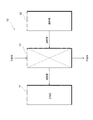
図1に示されるように、車両の吸気系10には、エンジン11に吸入される空気を過給する過給機12が設けられている。エンジン11と過給機12との間には熱交換器13が設けられている。熱交換器13は、過給機12により過給された空気と冷却水との間で熱交換を行うことにより、過給気を冷却してエンジン11に供給する。これにより、エンジン11に供給される空気の充填効率が向上するため、エンジン11の出力を高めることができる。本実施形態では、過給気が第1流体に相当し、冷却水が第2流体に相当する。
As shown in FIG. 1, an
次に、熱交換器13の構造について具体的に説明する。
図2に示されるように、熱交換器13は、熱交換部20と、タンク30,31と、パイプ40a,40bとを備えている。熱交換器13は、アルミニウム合金等の金属材料により形成されている。
Next, the structure of the
As shown in FIG. 2, the
熱交換部20は、略直方体状に形成されている。熱交換部20は、ダクトプレート50と、流入側かしめプレート52と、流出側かしめプレート53とを備えている。
ダクトプレート50は、四角筒状に形成されている。ダクトプレート50の一端部の開口部周縁には、四角環状に形成された流入側かしめプレート52がろう付けにより接合されている。流入側かしめプレート52には、流入側タンク30の一端部に形成された四角筒状の開口部がかしめられて固定されている。ダクトプレート50の他端部の開口部周縁には、四角環状に形成された流出側かしめプレート53がろう付けにより接合されている。流出側かしめプレート53には、流出側タンク31の一端部に形成された四角筒状の開口部がかしめられて固定されている。
The
The
ダクトプレート50の外壁部51には、冷却水が流入する流入パイプ40a、及び冷却水が排出される排出パイプ40bが設けられている。
この熱交換器13では、流入側タンク30の他端部30aに接続される配管を通じて流入側タンク30に過給気が流入する。流入側タンク30の他端部30aに流入した過給気は、流入側タンク30を通過してダクトプレート50の内部を図中に矢印Yで示される方向に流通している。ダクトプレート50を通過した過給気は、流出側タンク31の内部を流れるとともに、流出側タンク31の他端部31aに接続される配管に排出される。
The
In the
図3に示されるように、熱交換部20は、ダクトプレート50の内部に収容される熱交換コア部60を更に備えている。熱交換コア部60は、過給気と冷却水との間で実際に熱交換が行われる部分である。熱交換コア部60は、複数の冷却プレート61と、複数のアウタフィン62とを有している。
As shown in FIG. 3, the
複数の冷却プレート61は、所定の間隔をあけて積層して配置されている。各冷却プレート61は、一対のプレート部材を最中状に接合させることにより構成されている。各冷却プレート61の内部空間は、冷却水が流れる冷却水流路となっている。各冷却プレート61の冷却水流路は互いに連通されている。また、各冷却プレート61の冷却水流路は、流入パイプ40a、並びに図2に示される排出パイプ40bに連通されている。隣り合う冷却プレート61,61の間には、ダクトプレート50を流れる過給気が通過する隙間が形成されている。
The plurality of cooling
アウタフィン62は、隣り合う冷却プレート61,61の間の隙間に配置されている。アウタフィン62は、過給気に対する冷却プレート61の伝熱面積を増加させることにより熱交換器13の熱交換性能を高める機能を有している。
この熱交換器13では、流入パイプ40aに流入する冷却水が各冷却プレート61の内部の冷却水流路に分配される。各冷却プレート61の内部の冷却水流路を冷却水が流れる際に、冷却プレート61の外部を流れる過給気と冷却水との間で熱交換が行われることにより、過給気の熱を冷却水が吸収する。これにより、過給気が冷却される。過給気の熱を吸収することにより温度が上昇した冷却水は、排出パイプ40bから外部に排出される。
The
In this
次に、ダクトプレート50と各パイプ40a,40bとの接合部分の構造について具体的に説明する。なお、ダクトプレート50と排出パイプ40bとの接合部分の構造は、ダクトプレート50と流入パイプ40aとの接合部分の構造と同一であるため、以下ではダクトプレート50と流入パイプ40aとの接合部分の構造について代表して説明する。
Next, the structure of the joint portion between the
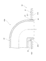
図4に示されるように、ダクトプレート50の外壁部51には、流入パイプ40aが挿入される挿入孔54が形成されている。挿入孔54は、バーリングが形成されていない形状を有している。ダクトプレート50の外壁部51の内面510には、ろう材が被覆されている。
As shown in FIG. 4, an
流入パイプ40aは、略L字状に形成されており、ダクトプレート50の外壁部51の外面511に対して直交する方向に延びるように形成される第1部位41と、第1部位41の先端部からダクトプレート50の外壁部51の外面511に対して平行に延びるように形成される第2部位42とを有している。流入パイプ40aの第1部位41の端部410は全周にわたって口拡されている。これにより、流入パイプ40aの端部410の外周部分が全周にわたってダクトプレート50の挿入孔54の内周面にかしめられている。
The
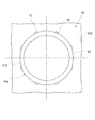
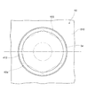
図5に示されるように、ダクトプレート50の挿入孔54の内周面には、断面半円形状の切欠きからなる複数のろう材流路80が形成されている。ろう材流路80は、図4に示されるダクトプレート50の外壁部51の内面510から外面511まで延びるように形成されている。図5に示されるように、流入パイプ40aの端部410の外周部分が全周にわたってダクトプレート50の挿入孔54の内周面に接触している場合であっても、ろう材流路80は閉塞されていない。そのため、ダクトプレート50の内面510に被覆されるろう材は、このろう材流路80を通じて、図4に示されるダクトプレート50の外壁部51の外面511に流れることが可能である。
As shown in FIG. 5, on the inner peripheral surface of the
図4に拡大して示されるように、流入パイプ40aの端部410の外周面とダクトプレート50の挿入孔54の内周面との間に形成される隙間には、ろう材流路80を通じてろう材70が流れ込んで充填されている。このろう材70により、流入パイプ40aとダクトプレート50とが接合されている。
As shown in an enlarged manner in FIG. 4, through the brazing filler
流入パイプ40aの第1部位41には、その外周部分から突出するように突出部43が形成されている。突出部43は、流入パイプ40aの第1部位41の外周部分のうち、第2部位42が延びる方向に対応する部位に形成されている。突出部43の底面430とダクトプレート50の外壁部51の外面511との間には、ろう材流路80を通じてろう材70が流れ込んで充填されている。このろう材70により、ダクトプレート50に対して流入パイプ40aが接合されている。
A
次に、ダクトプレート50の挿入孔54に対する流入パイプ40aの接合方法について具体的に説明する。
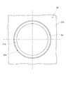
図6及び図7に示されるように、ダクトプレート50に流入パイプ40aが接合される前の状態では、流入パイプ40aの端部410の外径はダクトプレート50の挿入孔54の内径よりも小さい。そのため、ダクトプレート50の挿入孔54に流入パイプ40aの端部410を挿入することが可能となっている。
Next, a method of joining the
As shown in FIGS. 6 and 7, in the state before the
図6に示されるように、熱交換器13の各部品が組み付けられる組み付け工程において、流入パイプ40aの端部410はダクトプレート50の挿入孔54に挿入される。この際、流入パイプ40aの突出部43の底面430がダクトプレート50の外壁部51の外面511に接触することにより、ダクトプレート50の外壁部51の外面511に対する流入パイプ40aの第2部位42の位置が規定される。このように、本実施形態では、流入パイプ40aの突出部43が位置決め部として機能する。
As shown in FIG. 6, in the assembly process in which the components of the
組み付け工程において、流入パイプ40aの端部410が口拡されることにより、図4に示されるように、流入パイプ40aの端部410の外周部分が全周にわたってダクトプレート50の挿入孔54の内周面にかしめられる。これにより、ダクトプレート50に対して流入パイプ40aが仮固定される。
In the assembling process, the
組み付け工程に続いて、熱交換器13の各部品をろう付けにより接合する接合工程が行われる。接合工程では、まず、各部品の組立品に適宜の治具を取り付けることにより、各部品を組み付けた状態で保持する。その後、この治具が取り付けられた組立品を炉内に投入して各部品を加熱することにより、各部品の表面に被覆されたろう材を溶かす。これにより、各部品の接合部分にろう材が浸透する。
Subsequent to the assembling step, a joining step of joining the respective parts of the
その際、図8に矢印Rで示されるように、ダクトプレート50の外壁部51の内面510に被覆されたろう材がろう材流路80に流入する。ろう材流路80に流入したろう材は、流入パイプ40aの端部410の外周面とダクトプレート50の挿入孔54の内周面との間に形成される隙間、並びに流入パイプ40aの突出部43の底面430とダクトプレート50の外壁部51の外面511との間に形成される隙間に毛細管現象により流れ込む。
At that time, as shown by an arrow R in FIG. 8, the brazing material coated on the
その後、炉内から取り出された組立品が自然冷却等により冷却されることで、熱交換器13の各部品が接合される。これにより、図9に示されるように、流入パイプ40aの突出部43の底面430とダクトプレート50の外壁部51の外面511との間に形成される隙間に流れ込んだろう材70、並びにろう材流路80に流れ込んだろう材70が凝固する。同様に、流入パイプ40aの端部410の外周面とダクトプレート50の挿入孔54の内周面との間に形成される隙間に流れ込んだろう材70も凝固する。これにより、流入パイプ40aとダクトプレート50とがろう材70により接合される。
After that, the assembly taken out from the furnace is cooled by natural cooling or the like, so that the respective parts of the
以上説明した本実施形態の熱交換器13によれば、以下の(1)〜(5)に示される作用及び効果を得ることができる。
(1)ダクトプレート50の挿入孔54の内周面と流入パイプ40aの外周面との間には、ろう材流路80が形成されている。ろう材流路80は、ダクトプレート50の外壁部51の内面510から外面511まで延びるように形成されている。ろう材流路80には、ダクトプレート50の外壁部51の内面510に被覆されるろう材が流れ込む。このような構成によれば、ろう材流路80に流れ込むろう材によりダクトプレート50と流入パイプ40aとを接合することができる。また、ダクトプレート50の外壁部51の内面510にろう材70が被覆されているため、熱交換器13の各部品をろう付けする際に用いられる治具がろう材に接触することがない。そのため、外観不良の発生を低減することができる。
According to the
(1) A brazing filler
(2)ろう材流路80は、ダクトプレート50の挿入孔54の内周面に形成されている。このような構成によれば、ダクトプレート50の挿入孔54の内周面を加工するだけで、ろう材流路80を容易に形成することができる。
(3)図7に示されるように、ろう材流路80の流路幅H1は、ダクトプレート50の挿入孔54の内周面と流入パイプ40aの外周面との間に形成される隙間の幅H2よりも大きい。このような構成によれば、ろう材流路80にろう材が流れ込み易くなる。
(2) The brazing
(3) As shown in FIG. 7, the flow passage width H1 of the brazing filler
(4)流入パイプ40aの外周面の全周が、ダクトプレート50の挿入孔54の内周面にかしめられている。ろう材流路80は、ダクトプレート50の挿入孔54の内周面に形成されている。このような構成によれば、ダクトプレート50に対して流入パイプ40aを仮固定することが可能でありながら、流入パイプ40aとダクトプレート50との接合部分にろう材流路80を通じてろう材を流すことが可能となる。
(4) The entire outer peripheral surface of the
(5)流入パイプ40aの突出部43は、その底面430がダクトプレート50の外壁部51の外面511に接触することにより、ダクトプレート50の外壁部51の外面511に対する流入パイプ40aの第2部位42の位置を規定する位置決め部として機能する。このような構成によれば、ダクトプレート50の外壁部51の外面511に対する流入パイプ40aの第2部位42の位置を容易に規定することができる。
(5) The
(第1変形例)
次に、第1実施形態の熱交換器13の第1変形例について説明する。
図10に示されるように、本実施形態の熱交換器13では、流入パイプ40aの端部410が口拡されていない。このような構成であっても、ろう材流路80に流れ込むろう材70、並びにダクトプレート50の挿入孔54の内周面と流入パイプ40aの第1部位41の外周面との間の隙間に流れ込むろう材70により、ダクトプレート50に対して流入パイプ40aを接合することが可能である。
(First modification)
Next, the 1st modification of the
As shown in FIG. 10, in the
(第2変形例)
次に、第2実施形態の熱交換器13の第2変形例について説明する。
図11に示されるように、本実施形態の熱交換器13では、突出部43が、流入パイプ40aの第1部位41の全周にわたって形成されている。このような構成によれば、流入パイプ40aとダクトプレート50との接合部分の面積を増加させることができるため、流入パイプ40aとダクトプレート50との接合強度を向上させることができる。
(Second modified example)
Next, the 2nd modification of the
As shown in FIG. 11, in the
(第3変形例)
次に、第3実施形態の熱交換器13の第3変形例について説明する。
図12に示されるように、本実施形態の熱交換器13では、ダクトプレート50の挿入孔54に、ダクトプレート50の内部に突出するバーリング部541が形成されている。このような構造であっても、第1実施形態の熱交換器13の構造を適用可能である。
(Third modification)
Next, the 3rd modification of the
As shown in FIG. 12, in the
<第2実施形態>
次に、第2実施形態の熱交換器13について説明する。以下、第1実施形態の熱交換器13との相違点を中心に説明する。
図13に示されるように、本実施形態の熱交換器13では、流入パイプ40aの第1部位41の外周面に形成される突出部43に代えて、流入パイプ40aの第2部位42とダクトプレート50の外壁部51の外面511との間に挟み込まれるスペーサ部材90が配置されている。スペーサ部材90は、流入パイプ40a及びダクトプレート50とは別体からなる。このスペーサ部材90により、ダクトプレート50の外壁部51の外面511に対する流入パイプ40aの第2部位42の位置が規定されている。すなわち、本実施形態では、スペーサ部材90が位置決め部として機能している。
<Second Embodiment>
Next, the
As shown in FIG. 13, in the
以上説明した本実施形態の熱交換器13によれば、上記の(5)に代わる作用及び効果として、以下の(6)に示される作用及び効果を得ることができる。
(6)スペーサ部材90により、ダクトプレート50の外壁部51の外面511に対する流入パイプ40aの第2部位42の位置を容易に規定することができる。また、流入パイプ40aに突出部43を形成する場合と比較すると、流入パイプ40aの構造の複雑化を回避することができる。さらに、スペーサ部材90を両面クラッドとすることで、ダクト外面511と流入パイプ40aの第2部位42の下面とをスペーサ部材90を介してろう付けでき、パイプのろう付け強度を上げることも可能になる。
According to the
(6) The
<第3実施形態>
次に、熱交換器13の第3実施形態について説明する。以下、第1実施形態の熱交換器13との相違点について説明する。
図14に示されるように、本実施形態の流入パイプ40aの端部410は、その一部が径方向外側に向かって口拡されている。これにより、流入パイプ40aの端部410には、径方向外側に向かって突出する複数の突出部44が形成されている。複数の突出部44は、ダクトプレート50の挿入孔54の内周面にかしめられている。
<Third Embodiment>
Next, a third embodiment of the
As shown in FIG. 14, a part of the
流入パイプ40aの端部410において突出部44が形成されていない部分の外周面とダクトプレート50の挿入孔54の内周面との間には、隙間が形成されている。この隙間は、ダクトプレート50の外壁部51の内面510に被覆されたろう材が流れ込むろう材流路80となっている。このろう材流路80に充填されるろう材70により、流入パイプ40aとダクトプレート50とが接合されている。
A gap is formed between the outer peripheral surface of the
次に、本実施形態のダクトプレート50の挿入孔54に対する流入パイプ40aの接合方法について具体的に説明する。
本実施形態の熱交換器13の組み付け工程では、図15に示されるように、流入パイプ40aの端部410がダクトプレート50の挿入孔54に挿入された後、図16に二点鎖線で示される治具100を用いて流入パイプ40aの端部410が口拡される。治具100は多角形の外形を有している。この治具100を用いて流入パイプ40aの端部410が口拡されることにより、流入パイプ40aの端部410に複数の突出部44が形成されて、図14に示されるように、複数の突出部44がダクトプレート50の挿入孔54の内周面にかしめられる。これにより、ダクトプレート50に対して流入パイプ40aが仮固定される。これ以降、上述した接合工程が行われることにより、熱交換器13の各部品が接合される。
Next, a method of joining the
In the assembling process of the
以上説明した本実施形態の熱交換器13によれば、上記の(4)に代わる作用及び効果として、以下の(6)に示される作用及び効果を得ることができる。
(6)流入パイプ40aの外周面の一部が、ダクトプレート50の挿入孔54の内周面にかしめられているため、ダクトプレート50に対して流入パイプ40aを仮固定することが可能である。また、ろう材流路80は、流入パイプ40aの外周面においてダクトプレート50の挿入孔54の内周面にかしめられていない部分と、ダクトプレート50の挿入孔54の内周面との間に形成される隙間により形成されている。そのため、このろう材流路80を通じて流入パイプ40aとダクトプレート50との接合部分にろう材流路80を通じてろう材を流すことが可能である。
According to the
(6) Since a part of the outer peripheral surface of the
<他の実施形態>
なお、上記実施形態は、以下の形態にて実施することもできる。
・一つの流入パイプ40aに対して形成されるろう材流路80の数は適宜変更可能である。一つの流入パイプ40aに対して形成されるろう材流路80の数は少なくとも一つであればよい。
<Other Embodiments>
In addition, the above-mentioned embodiment can also be implemented in the following forms.
-The number of brazing
・ろう材流路80は、ダクトプレート50の挿入孔54の内周面に限らず、流入パイプ40aの外周面に形成されていてもよい。あるいは、ろう材流路80は、ダクトプレート50の挿入孔54の内周面、及び流入パイプ40aの外周面の両方に形成されていてもよい。
The brazing filler
・ダクトプレート50を流れる第1流体としては、過給気に限らず、適宜の流体を用いることができる。同様に、冷却プレート61を流れる第2流体としては、冷却水に限らず、適宜の流体を用いることができる。
・本開示は上記の具体例に限定されるものではない。上記の具体例に、当業者が適宜設計変更を加えたものも、本開示の特徴を備えている限り、本開示の範囲に包含される。前述した各具体例が備える各要素、及びその配置、条件、形状等は、例示したものに限定されるわけではなく適宜変更することができる。前述した各具体例が備える各要素は、技術的な矛盾が生じない限り、適宜組み合わせを変えることができる。
The first fluid flowing through the
The present disclosure is not limited to the above specific examples. A person skilled in the art appropriately modified the above-described specific examples is also included in the scope of the present disclosure as long as the features of the present disclosure are provided. The elements included in the above-described specific examples, and the arrangement, conditions, shapes, and the like of the elements are not limited to those illustrated, but can be appropriately changed. The respective elements included in the above-described specific examples can be appropriately combined as long as there is no technical contradiction.
13:熱交換器
40a:流入パイプ
40b:排出パイプ
41:第1部位
42:第2部位
43:突出部(位置決め部)
50:ダクトプレート
51:外壁部
54:挿入孔
61:冷却プレート
70:ろう材
80:ろう材流路
90:スペーサ部材(位置決め部)
541:バーリング部
13:
50: Duct plate 51: Outer wall 54: Insertion hole 61: Cooling plate 70: Brazing material 80: Brazing material flow channel 90: Spacer member (positioning part)
541: Burring unit
Claims (10)
前記第1流体が内部を流通する筒状のダクトプレート(50)と、
前記ダクトプレートの内部に積層して配置され、前記第2流体の流れる冷却水流路が内部に形成される複数の冷却プレート(61)と、
前記ダクトプレートの外壁部(51)に形成された挿入孔(54)に挿入され、前記第2流体が流入又は排出されるパイプ(40a,40b)と、を備え、
前記ダクトプレートの前記外壁部の内面には、ろう材が被覆され、
前記挿入孔の内周面と前記パイプの外周面との間には、前記ダクトプレートの前記外壁部の内面から外面まで延びるようにろう材流路(80)が形成され、
前記ろう材流路には、前記ダクトプレートの前記外壁部の内面に被覆されるろう材(70)が流れ込んでいる
熱交換器。 A heat exchanger (13) for exchanging heat between a first fluid and a second fluid, comprising:
A tubular duct plate (50) through which the first fluid flows,
A plurality of cooling plates (61) arranged inside the duct plate so as to be laminated and having therein a cooling water passage through which the second fluid flows;
Pipes (40a, 40b) that are inserted into the insertion holes (54) formed in the outer wall portion (51) of the duct plate and through which the second fluid flows in or out,
An inner surface of the outer wall portion of the duct plate is coated with a brazing material,
Between the inner peripheral surface of the insertion hole and the outer peripheral surface of the pipe, a brazing material flow path (80) is formed so as to extend from the inner surface of the outer wall portion of the duct plate to the outer surface,
A heat exchanger in which a brazing material (70) coated on the inner surface of the outer wall portion of the duct plate flows into the brazing material flow path.
請求項1に記載の熱交換器。 The heat exchange according to claim 1, wherein at least one brazing material channel is formed for each of the pipes, and is formed on at least one of an outer peripheral surface of the pipe and an inner peripheral surface of the insertion hole. vessel.
請求項1又は2に記載の熱交換器。 The heat exchanger according to claim 1 or 2, wherein a flow passage width of the brazing filler metal flow passage is larger than a width of a gap formed between an inner peripheral surface of the insertion hole and an outer peripheral surface of the pipe.
前記ろう材流路は、前記パイプの外周面又は前記挿入孔の内周面の少なくとも一方に形成されている
請求項1に記載の熱交換器。 The entire outer peripheral surface of the pipe is crimped to the inner peripheral surface of the insertion hole,
The heat exchanger according to claim 1, wherein the brazing material flow path is formed on at least one of an outer peripheral surface of the pipe and an inner peripheral surface of the insertion hole.
前記ろう材流路は、前記パイプの外周面において前記挿入孔の内周面にかしめられていない部分と前記挿入孔の内周面との間に設けられる隙間により形成されている
請求項1に記載の熱交換器。 A part of the outer peripheral surface of the pipe is crimped to the inner peripheral surface of the insertion hole,
The brazing material flow path is formed by a gap provided between a portion of the outer peripheral surface of the pipe that is not crimped on the inner peripheral surface of the insertion hole and the inner peripheral surface of the insertion hole. The heat exchanger described.
請求項1〜5のいずれか一項に記載の熱交換器。 The heat exchanger according to claim 1, wherein the insertion hole has a shape in which a burring portion is not formed.
請求項1〜5のいずれか一項に記載の熱交換器。 The heat exchanger according to any one of claims 1 to 5, wherein the insertion hole is formed with a burring portion (541) projecting from an inner peripheral surface thereof toward the inside of the duct plate.
前記ダクトプレートの前記外壁部の外面に対する前記パイプの前記第2部位の位置を規定する位置決め部(43,90)を更に備える
請求項1〜7のいずれか一項に記載の熱交換器。 The pipe has a first portion (41) extending from the insertion hole in a direction orthogonal to an outer surface of the outer wall portion of the duct plate, and an outer surface of the outer wall portion of the duct plate from a tip portion of the first portion. A second portion (42) extending parallel to the
The heat exchanger according to claim 1, further comprising a positioning portion (43, 90) that defines a position of the second portion of the pipe with respect to an outer surface of the outer wall portion of the duct plate.
前記突出部は、前記ダクトプレートの前記外壁部の外面に接触することにより前記ダクトプレートの前記外壁部の外面に対する前記パイプの前記第2部位の位置を規定している
請求項8に記載の熱交換器。 The positioning portion includes a protrusion (43) formed to protrude from the outer peripheral surface of the first portion of the pipe,
The heat of claim 8, wherein the protrusion defines a position of the second portion of the pipe with respect to an outer surface of the outer wall portion of the duct plate by contacting an outer surface of the outer wall portion of the duct plate. Exchanger.
請求項8に記載の熱交換器。 The positioning member is a separate member from the pipe and the duct plate, and is arranged so as to be sandwiched between the second portion of the pipe and the outer surface of the outer wall portion of the duct plate ( 90) The heat exchanger according to claim 8.
Priority Applications (4)
| Application Number | Priority Date | Filing Date | Title |
|---|---|---|---|
| JP2018217485A JP2020085288A (en) | 2018-11-20 | 2018-11-20 | Heat exchanger |
| PCT/JP2019/043485 WO2020105435A1 (en) | 2018-11-20 | 2019-11-06 | Heat exchanger |
| CN201980076499.5A CN113167553A (en) | 2018-11-20 | 2019-11-06 | Heat exchanger |
| US17/322,551 US20210270548A1 (en) | 2018-11-20 | 2021-05-17 | Heat exchanger |
Applications Claiming Priority (1)
| Application Number | Priority Date | Filing Date | Title |
|---|---|---|---|
| JP2018217485A JP2020085288A (en) | 2018-11-20 | 2018-11-20 | Heat exchanger |
Publications (2)
| Publication Number | Publication Date |
|---|---|
| JP2020085288A true JP2020085288A (en) | 2020-06-04 |
| JP2020085288A5 JP2020085288A5 (en) | 2021-04-30 |
Family
ID=70774443
Family Applications (1)
| Application Number | Title | Priority Date | Filing Date |
|---|---|---|---|
| JP2018217485A Pending JP2020085288A (en) | 2018-11-20 | 2018-11-20 | Heat exchanger |
Country Status (4)
| Country | Link |
|---|---|
| US (1) | US20210270548A1 (en) |
| JP (1) | JP2020085288A (en) |
| CN (1) | CN113167553A (en) |
| WO (1) | WO2020105435A1 (en) |
Citations (8)
| Publication number | Priority date | Publication date | Assignee | Title |
|---|---|---|---|---|
| JPS5623874U (en) * | 1979-07-26 | 1981-03-04 | ||
| JPS6234964U (en) * | 1985-08-22 | 1987-03-02 | ||
| JPS635294U (en) * | 1986-06-26 | 1988-01-14 | ||
| JPH08327280A (en) * | 1995-05-30 | 1996-12-13 | Sanden Corp | Fluid supply/drain pipe joint structure of heat exchanger |
| JPH11281292A (en) * | 1998-03-30 | 1999-10-15 | Denso Corp | Lamination-type heat exchanger |
| JPH11281289A (en) * | 1998-03-31 | 1999-10-15 | Calsonic Corp | Tank for heat exchanger |
| JP2005172270A (en) * | 2003-12-08 | 2005-06-30 | Calsonic Kansei Corp | Radiator incorporated with oil cooler |
| JP2018136064A (en) * | 2017-02-21 | 2018-08-30 | 株式会社デンソー | Heat exchanger |
Family Cites Families (42)
| Publication number | Priority date | Publication date | Assignee | Title |
|---|---|---|---|---|
| US2217000A (en) * | 1937-11-26 | 1940-10-08 | Universal Oil Prod Co | Fluid conduit |
| US2195403A (en) * | 1939-04-14 | 1940-04-02 | Thomas J Bay | Condenser tube protector |
| US2225615A (en) * | 1940-01-08 | 1940-12-24 | Thomas J Bay | Condenser tube protector |
| US2620830A (en) * | 1950-02-18 | 1952-12-09 | Schultz Herman | Self-sealing tube insert |
| US3317222A (en) * | 1964-04-16 | 1967-05-02 | Cons Edison Co New York Inc | Insert constructions for tubes of heat exchangers and condensers |
| US3349465A (en) * | 1965-05-14 | 1967-10-31 | United Aircraft Corp | Tube-to-sheet joint making |
| US3400755A (en) * | 1967-02-02 | 1968-09-10 | Ingersoll Rand Co | Method and article for protecting condenser tubes |
| US3844588A (en) * | 1972-06-21 | 1974-10-29 | Ingersoll Rand Co | Condenser tube support plate insert |
| US3857151A (en) * | 1973-10-15 | 1974-12-31 | Young Radiation Co | Method of making a radiator core |
| JPS5157488A (en) * | 1974-11-14 | 1976-05-19 | Shimadzu Corp | RIIKUTE SUTOHOHO |
| GB1591842A (en) * | 1977-02-11 | 1981-06-24 | Serck Industries Ltd | Method of and apparatus for joining a tubular element to a support |
| JPS57144895A (en) * | 1981-03-04 | 1982-09-07 | Hitachi Ltd | Fin and tube type of heat exchanger |
| US4528733A (en) * | 1983-07-25 | 1985-07-16 | United Aircraft Products, Inc. | Method of making tubular heat exchangers |
| JPH037757Y2 (en) * | 1986-02-27 | 1991-02-26 | ||
| JPS6317395A (en) * | 1986-07-09 | 1988-01-25 | Hitachi Ltd | Joint structure between pipe and tube plate |
| JPH069738Y2 (en) * | 1987-01-23 | 1994-03-16 | 株式会社ゼクセル | Brazing structure of pipe material |
| US4941512A (en) * | 1988-11-14 | 1990-07-17 | Cti Industries, Inc. | Method of repairing heat exchanger tube ends |
| CN1162109A (en) * | 1995-05-30 | 1997-10-15 | 三电有限公司 | Heat exchanger and mfg. method thereof |
| CN1153690A (en) * | 1996-01-05 | 1997-07-09 | 黄月义 | Welding method and material for the welding between the pipe with infiltrated metal layer and the plate |
| JP3808578B2 (en) * | 1997-02-21 | 2006-08-16 | カルソニックカンセイ株式会社 | Pipe mounting structure to heat exchanger tank |
| JP3054939B2 (en) * | 1997-03-31 | 2000-06-19 | 株式会社ゼクセル | Stacked heat exchanger |
| KR19980080427A (en) * | 1997-04-09 | 1998-11-25 | 다카노야스아키 | Absorption Chiller |
| DE19719259B4 (en) * | 1997-05-07 | 2005-08-18 | Valeo Klimatechnik Gmbh & Co. Kg | Flat tube heat exchanger for motor vehicles with flat tubes held on collars of a tube plate |
| JPH1151591A (en) * | 1997-08-01 | 1999-02-26 | Calsonic Corp | Laminated type heat exchanger |
| US6138747A (en) * | 1999-02-17 | 2000-10-31 | Dehr Heat Transfer System, Inc. | Heat exchanger tube to header swaging process |
| JP4588933B2 (en) * | 2001-07-10 | 2010-12-01 | 株式会社ティラド | Connection structure between resin pipe and tank |
| EP1479996B1 (en) * | 2003-05-20 | 2007-01-24 | Behr France Rouffach SAS | Pipe coupling for heat exchanger, particularly for vehicle radiators |
| JP2005121350A (en) * | 2003-05-29 | 2005-05-12 | Denso Corp | Heat exchanger and method for manufacturing it |
| DE10343634A1 (en) * | 2003-09-20 | 2005-04-14 | Modine Manufacturing Co., Racine | Heat exchanger for a motor vehicle comprises sealing caps for sealing lateral openings in collecting tanks and having fixing elements for fixing the walls of the collecting tanks during insertion into the lateral openings |
| US7380327B2 (en) * | 2005-01-20 | 2008-06-03 | Calsonickansei North America, Inc. | Tube interface and method of securing a first tube to a second tube |
| JP5741931B2 (en) * | 2011-05-31 | 2015-07-01 | 株式会社ノーリツ | Heat exchanger |
| JP6124044B2 (en) * | 2011-07-20 | 2017-05-10 | 京進工業株式会社 | Manufacturing method of gripping body of heat exchanger insertion tube |
| KR20140011182A (en) * | 2012-07-18 | 2014-01-28 | 김영진 | Aluminum heat exchanger |
| DE102012108821B4 (en) * | 2012-09-19 | 2014-08-14 | Benteler Automobiltechnik Gmbh | Method for producing a heat exchanger |
| CN104768690B (en) * | 2012-11-14 | 2017-05-10 | 松下电器产业株式会社 | Al alloy pipe assembly and heat exchanger using same |
| KR20150053135A (en) * | 2013-11-07 | 2015-05-15 | 엘지전자 주식회사 | Heat exchanger and Manufacturing method fo the same |
| JP6207724B2 (en) * | 2014-04-21 | 2017-10-04 | 三菱電機株式会社 | Header distributor, heat exchanger, air conditioner, and header distributor manufacturing method |
| JP6587098B2 (en) * | 2015-10-29 | 2019-10-09 | パナソニックIpマネジメント株式会社 | Brazing material for brazing heat exchanger aluminum tube, joining method of aluminum tube using heat exchanger, and joining structure of aluminum tube for heat exchanger |
| EP3309495B1 (en) * | 2016-08-08 | 2019-04-17 | Mitsubishi Electric Corporation | Laminated header and method for manufacturing laminated header |
| EP3499171A1 (en) * | 2017-12-15 | 2019-06-19 | ALFA LAVAL OLMI S.p.A. | Anti-erosion device for a shell-and-tube equipment |
| JP7004208B2 (en) * | 2017-12-26 | 2022-02-04 | 株式会社ノーリツ | How to make a heat exchanger |
| JP7293570B2 (en) * | 2019-03-25 | 2023-06-20 | 株式会社ノーリツ | Heat exchanger and manufacturing method thereof |
-
2018
- 2018-11-20 JP JP2018217485A patent/JP2020085288A/en active Pending
-
2019
- 2019-11-06 WO PCT/JP2019/043485 patent/WO2020105435A1/en active Application Filing
- 2019-11-06 CN CN201980076499.5A patent/CN113167553A/en active Pending
-
2021
- 2021-05-17 US US17/322,551 patent/US20210270548A1/en not_active Abandoned
Patent Citations (8)
| Publication number | Priority date | Publication date | Assignee | Title |
|---|---|---|---|---|
| JPS5623874U (en) * | 1979-07-26 | 1981-03-04 | ||
| JPS6234964U (en) * | 1985-08-22 | 1987-03-02 | ||
| JPS635294U (en) * | 1986-06-26 | 1988-01-14 | ||
| JPH08327280A (en) * | 1995-05-30 | 1996-12-13 | Sanden Corp | Fluid supply/drain pipe joint structure of heat exchanger |
| JPH11281292A (en) * | 1998-03-30 | 1999-10-15 | Denso Corp | Lamination-type heat exchanger |
| JPH11281289A (en) * | 1998-03-31 | 1999-10-15 | Calsonic Corp | Tank for heat exchanger |
| JP2005172270A (en) * | 2003-12-08 | 2005-06-30 | Calsonic Kansei Corp | Radiator incorporated with oil cooler |
| JP2018136064A (en) * | 2017-02-21 | 2018-08-30 | 株式会社デンソー | Heat exchanger |
Also Published As
| Publication number | Publication date |
|---|---|
| WO2020105435A1 (en) | 2020-05-28 |
| CN113167553A (en) | 2021-07-23 |
| US20210270548A1 (en) | 2021-09-02 |
Similar Documents
| Publication | Publication Date | Title |
|---|---|---|
| US8261815B2 (en) | Heat exchanger, in particular charge air cooler or exhaust gas cooler for an internal combustion engine of a motor vehicle and method for manufacturing it | |
| JP2001099585A (en) | Heat exchanger made of aluminum | |
| KR100677719B1 (en) | Brazing method and brazing structure | |
| JP6197338B2 (en) | Heat exchanger | |
| US20070000652A1 (en) | Heat exchanger with dimpled tube surfaces | |
| US20080237312A1 (en) | Brazing method | |
| JP5420970B2 (en) | Heat exchanger | |
| US7322403B2 (en) | Heat exchanger with modified tube surface feature | |
| JPH0989491A (en) | Egr gas cooling device | |
| JP6601384B2 (en) | Intercooler | |
| JP2016070655A (en) | Heat exchanger | |
| JP7314655B2 (en) | Heat exchanger | |
| WO2020105435A1 (en) | Heat exchanger | |
| JP2012159211A (en) | Heat exchanger | |
| JP4787511B2 (en) | Joining structure of heat exchanger and joining method thereof | |
| JPH0749264Y2 (en) | Heat exchanger | |
| JP5359288B2 (en) | Heat exchanger | |
| JP2009243563A (en) | Pipe coupling structure with hollow component | |
| KR20090029861A (en) | Oilcooler and radiator assembly, and manufacturing method thereof | |
| JP6862773B2 (en) | Heat exchanger | |
| JPH09250888A (en) | Double-piped heat exchanger | |
| JP3770684B2 (en) | Aluminum alloy heat exchanger | |
| JP2006234318A (en) | Heat exchanger | |
| JP2018204578A (en) | Heat exchanger | |
| JP2004069210A (en) | Multi-pipe type heat exchanger and manufacturing method thereof |
Legal Events
| Date | Code | Title | Description |
|---|---|---|---|
| A521 | Request for written amendment filed |
Free format text: JAPANESE INTERMEDIATE CODE: A523 Effective date: 20210319 |
|
| A621 | Written request for application examination |
Free format text: JAPANESE INTERMEDIATE CODE: A621 Effective date: 20211004 |
|
| A131 | Notification of reasons for refusal |
Free format text: JAPANESE INTERMEDIATE CODE: A131 Effective date: 20220913 |
|
| A02 | Decision of refusal |
Free format text: JAPANESE INTERMEDIATE CODE: A02 Effective date: 20230307 |