KR20140011182A - Aluminum heat exchanger - Google Patents
Aluminum heat exchanger Download PDFInfo
- Publication number
- KR20140011182A KR20140011182A KR1020120078136A KR20120078136A KR20140011182A KR 20140011182 A KR20140011182 A KR 20140011182A KR 1020120078136 A KR1020120078136 A KR 1020120078136A KR 20120078136 A KR20120078136 A KR 20120078136A KR 20140011182 A KR20140011182 A KR 20140011182A
- Authority
- KR
- South Korea
- Prior art keywords
- plate
- heat
- aluminum
- hairpin
- heat exchanger
- Prior art date
Links
Images


Classifications
-
- B—PERFORMING OPERATIONS; TRANSPORTING
- B23—MACHINE TOOLS; METAL-WORKING NOT OTHERWISE PROVIDED FOR
- B23K—SOLDERING OR UNSOLDERING; WELDING; CLADDING OR PLATING BY SOLDERING OR WELDING; CUTTING BY APPLYING HEAT LOCALLY, e.g. FLAME CUTTING; WORKING BY LASER BEAM
- B23K1/00—Soldering, e.g. brazing, or unsoldering
- B23K1/0008—Soldering, e.g. brazing, or unsoldering specially adapted for particular articles or work
- B23K1/0012—Brazing heat exchangers
-
- B—PERFORMING OPERATIONS; TRANSPORTING
- B23—MACHINE TOOLS; METAL-WORKING NOT OTHERWISE PROVIDED FOR
- B23K—SOLDERING OR UNSOLDERING; WELDING; CLADDING OR PLATING BY SOLDERING OR WELDING; CUTTING BY APPLYING HEAT LOCALLY, e.g. FLAME CUTTING; WORKING BY LASER BEAM
- B23K1/00—Soldering, e.g. brazing, or unsoldering
- B23K1/008—Soldering within a furnace
-
- F—MECHANICAL ENGINEERING; LIGHTING; HEATING; WEAPONS; BLASTING
- F28—HEAT EXCHANGE IN GENERAL
- F28F—DETAILS OF HEAT-EXCHANGE AND HEAT-TRANSFER APPARATUS, OF GENERAL APPLICATION
- F28F21/00—Constructions of heat-exchange apparatus characterised by the selection of particular materials
- F28F21/08—Constructions of heat-exchange apparatus characterised by the selection of particular materials of metal
- F28F21/081—Heat exchange elements made from metals or metal alloys
- F28F21/084—Heat exchange elements made from metals or metal alloys from aluminium or aluminium alloys
-
- F—MECHANICAL ENGINEERING; LIGHTING; HEATING; WEAPONS; BLASTING
- F28—HEAT EXCHANGE IN GENERAL
- F28F—DETAILS OF HEAT-EXCHANGE AND HEAT-TRANSFER APPARATUS, OF GENERAL APPLICATION
- F28F9/00—Casings; Header boxes; Auxiliary supports for elements; Auxiliary members within casings
- F28F9/02—Header boxes; End plates
- F28F9/04—Arrangements for sealing elements into header boxes or end plates
- F28F9/16—Arrangements for sealing elements into header boxes or end plates by permanent joints, e.g. by rolling
- F28F9/18—Arrangements for sealing elements into header boxes or end plates by permanent joints, e.g. by rolling by welding
-
- B—PERFORMING OPERATIONS; TRANSPORTING
- B23—MACHINE TOOLS; METAL-WORKING NOT OTHERWISE PROVIDED FOR
- B23K—SOLDERING OR UNSOLDERING; WELDING; CLADDING OR PLATING BY SOLDERING OR WELDING; CUTTING BY APPLYING HEAT LOCALLY, e.g. FLAME CUTTING; WORKING BY LASER BEAM
- B23K2101/00—Articles made by soldering, welding or cutting
- B23K2101/04—Tubular or hollow articles
- B23K2101/14—Heat exchangers
-
- F—MECHANICAL ENGINEERING; LIGHTING; HEATING; WEAPONS; BLASTING
- F28—HEAT EXCHANGE IN GENERAL
- F28F—DETAILS OF HEAT-EXCHANGE AND HEAT-TRANSFER APPARATUS, OF GENERAL APPLICATION
- F28F2275/00—Fastening; Joining
- F28F2275/04—Fastening; Joining by brazing
Abstract
Description
The present invention relates to an aluminum heat exchanger, and more particularly, by interconnecting a fin part coated with a clad material and a heat pipe, connecting a plurality of heat pipes by a hair fin coated with a clad material, and then passing a brazing furnace, As the clad material melts, the fin part, the heat pipe, and the hairpin are easily welded to each other to improve thermal contact. Therefore, the overall efficiency is increased due to heat conductivity due to heat exchange. And the heat exchanger tube is prevented, and the plate plate and the heat exchanger tube of the fin part are formed of aluminum material, thereby making it easy to manufacture in various forms, coating the clad material easily, and thereby facilitating brazing joining. will be.
In the
As described above, in the prior art, in the heat exchange between the heat medium refrigerant and air, air passes from the front to the rear of the heat exchanger, and the refrigerant flows from left to right to right to left according to the U-band connection direction between the horizontal tubes, which is a forming method of the heat exchanger. During the heat exchange between the refrigerant and the air.
Here, the heat exchanger of the heat pump system is divided into a condenser that utilizes the exothermic effect of the refrigerant and an evaporator that utilizes the heat absorbing action of the refrigerant in accordance with heat generation and heat absorption according to the change of state of the refrigerant.
However, in the
In addition, since the
Also, when the
SUMMARY OF THE INVENTION Accordingly, the present invention has been made keeping in mind the above problems occurring in the prior art,
By interconnecting the fin material coated with the clad material and the heat pipe, connecting the plurality of heat pipes by the hairpin coated with the clad material, and passing through the brazing furnace, the clad material melts, so that the fin part, the heat pipe and the hairpin are easily interconnected. In order to provide an aluminum heat exchanger that is welded and bonded, the thermal contact is improved, and thus, the overall efficiency is increased due to heat conductivity due to heat exchange. There is this.
In addition, by forming the plate plate and the heat transfer tube of the fin part made of aluminum, it is another object to provide an aluminum heat exchanger that is easy to manufacture in a variety of forms, easy to coat the clad material, thereby easy brazing bonding. .
In order to achieve the above object, the present invention is formed of a plurality of plate plates formed with a plurality of through-holes on one side of the aluminum material is spaced apart from each other, the outside of the plate plate is coated with a clad (clad) material;
A heat transfer tube made of aluminum and horizontally inserted into a through hole of the plate plate in a state where one side thereof is bent in a “U” shape, and having a plurality of plates formed in the longitudinal direction of the plate plate such that refrigerant transferred therein is heat-exchanged with the fin part;
A hairpin connected to the other side of the heat transfer tube such that a plurality of heat transfer tubes formed in the longitudinal direction of the plate plate are connected in series, and coated with a clad material therein;
It is configured to include, and after the fin portion, the heat pipe and the hairpin is connected, passing through a brazing furnace is related to an aluminum heat exchanger, characterized in that welded by the clad material.
As described above, the aluminum heat exchanger of the present invention interconnects the fin parts coated with the clad material and the heat pipe, connects the plurality of heat pipes by the hair fin coated with the clad material, and then passes the brazing furnace, As the clad material melts, the fin part, the heat pipe, and the hairpin are easily welded to each other to improve thermal contact. Therefore, the overall efficiency is increased due to heat conductivity due to heat exchange. And there is an effect that the heat pipe damage and the like is prevented.
In addition, by forming the plate plate and the heat transfer tube of the fin portion made of aluminum, it is easy to manufacture in various forms, coating the clad material is easy, and thereby brazing bonding is easy.
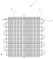
1 is a front view showing a conventional heat exchanger,
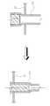
2 is a cross-sectional view showing a conventional heat exchanger,
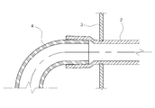
3 is an enlarged view illustrating a portion A of FIG. 2;
4 is a perspective view showing an aluminum heat exchanger according to an embodiment of the present invention,
5 is a cross-sectional view showing an aluminum heat exchanger according to an embodiment of the present invention;
6 is an enlarged view illustrating a portion A of FIG. 5;
7 is a cross-sectional view showing an aluminum heat exchanger according to another embodiment of the present invention.
The present invention has the following features in order to achieve the above object.
The present invention is formed of a plurality of plate plates formed with a plurality of through holes on one end of the aluminum material spaced apart from each other, the outside of the plate plate is coated with a clad (clad) material;
A heat transfer tube made of aluminum and horizontally inserted into a through hole of the plate plate in a state where one side thereof is bent in a “U” shape, and having a plurality of plates formed in the longitudinal direction of the plate plate such that refrigerant transferred therein is heat-exchanged with the fin part;
A hairpin connected to the other side of the heat transfer tube such that a plurality of heat transfer tubes formed in the longitudinal direction of the plate plate are connected in series, and coated with a clad material therein;
It is configured to include, and after the fin portion, the heat pipe and the hairpin is connected, passing through the brazing furnace is characterized in that the mutual welding by the clad material.
The present invention having such characteristics can be more clearly described by the preferred embodiments thereof.
DETAILED DESCRIPTION OF THE PREFERRED EMBODIMENTS Before describing in detail several embodiments of the present invention with reference to the accompanying drawings, it is to be understood that the present invention is not limited to the details of construction and the arrangement of components shown in the following detailed description or illustrated in the drawings will be. The invention may be embodied and carried out in other embodiments and carried out in various ways. It should also be noted that the device or element orientation (e.g., "front," "back," "up," "down," "top," "bottom, Expressions and predicates used herein for terms such as "left," " right, "" lateral, " and the like are used merely to simplify the description of the present invention, Or that the element has to have a particular orientation. Also, terms such as " first "and" second "are used herein for the purpose of the description and the appended claims, and are not intended to indicate or imply their relative importance or purpose.
Therefore, the embodiments described in this specification and the configurations shown in the drawings are merely the most preferred embodiments of the present invention and do not represent all the technical ideas of the present invention. Therefore, It is to be understood that equivalents and modifications are possible.
4 is a perspective view showing an aluminum heat exchanger according to an embodiment of the present invention, Figure 5 is a cross-sectional view showing an aluminum heat exchanger according to an embodiment of the present invention, Figure 6 is an enlarged view showing a portion A of FIG. 7 is a cross-sectional view showing an aluminum heat exchanger according to another embodiment of the present invention.
4 to 7, the
4 to 6, one fin is formed in the form of a plate plate, the
Here, the
In addition, the outside of the
The
Here, the
At this time, the
4 to 5, the
Here, the
The
In addition, the
As described above, the
On the other hand, in another embodiment in the
On the other hand, as another embodiment in the
Here, the
10: pin portion 11: plate plate
12 through
30: hairpin 40: clad material
50: heat exchanger
Claims (3)
One side of the aluminum plate is horizontally inserted into the through-hole 12 of the plate plate 11 in a state of being bent in a “U” shape, and a plurality of plates are formed in the longitudinal direction of the plate plate 11 to be transferred therein. A heat exchanger tube 20 through which the refrigerant is heat-exchanged with the fin part 10;
A hairpin 30 connected to the other side of the heat transfer pipe 20 so that a plurality of heat transfer pipes 20 formed in the longitudinal direction of the plate plate 11 are connected in series, and coated with a clad material inside thereof;
It is configured to include, the fin portion 10 and the heat pipe 20 and the hairpin 30 is connected, and then passed through the brazing furnace welded by the cladding material 40 of the pin portion 10 and the hairpin 30. Aluminum heat exchanger, characterized in that the.
One side of the aluminum plate is horizontally inserted into the through-hole 12 of the plate plate 11 in a state of being bent in a “U” shape, and a plurality of plates are formed in the longitudinal direction of the plate plate 11 to be transferred therein. A heat exchanger tube 20 in which the refrigerant is heat-exchanged with the fin part 10, and the outside of which is coated with a clad material;
A hairpin 30 connected to the other side of the heat transfer pipe 20 so that the heat transfer pipe 20 formed in plural in the longitudinal direction of the plate plate 11 is connected in series;
It is configured to include, and the fin portion 10 and the heat transfer pipe 20 and the hairpin 30 is connected, passing through the brazing furnace, characterized in that the mutual welding by the clad material 40 of the heat transfer pipe 20 Aluminum heat exchanger.
One side of the aluminum plate is horizontally inserted into the through-hole 12 of the plate plate 11 in a state of being bent in a “U” shape, and a plurality of plates are formed in the longitudinal direction of the plate plate 11 to be transferred therein. A heat exchanger tube 20 in which the refrigerant is heat-exchanged with the fin part 10, and the outside of which is coated with a clad material;
A hairpin 30 connected to the other side of the heat pipe 20 so that a plurality of heat pipes 20 formed in the longitudinal direction of the plate plate 11 are connected in series and coated with a clad material on the outside thereof;
It is configured to include, the fin portion 10 and the heat transfer pipe 20 and the hairpin 30 is connected, passing through the brazing furnace welded mutually by the cladding material 40 of the heat transfer pipe 20 and the hairpin 30. Aluminum heat exchanger, characterized in that the.
Priority Applications (1)
| Application Number | Priority Date | Filing Date | Title |
|---|---|---|---|
| KR1020120078136A KR20140011182A (en) | 2012-07-18 | 2012-07-18 | Aluminum heat exchanger |
Applications Claiming Priority (1)
| Application Number | Priority Date | Filing Date | Title |
|---|---|---|---|
| KR1020120078136A KR20140011182A (en) | 2012-07-18 | 2012-07-18 | Aluminum heat exchanger |
Publications (1)
| Publication Number | Publication Date |
|---|---|
| KR20140011182A true KR20140011182A (en) | 2014-01-28 |
Family
ID=50143539
Family Applications (1)
| Application Number | Title | Priority Date | Filing Date |
|---|---|---|---|
| KR1020120078136A KR20140011182A (en) | 2012-07-18 | 2012-07-18 | Aluminum heat exchanger |
Country Status (1)
| Country | Link |
|---|---|
| KR (1) | KR20140011182A (en) |
Cited By (1)
| Publication number | Priority date | Publication date | Assignee | Title |
|---|---|---|---|---|
| US20210270548A1 (en) * | 2018-11-20 | 2021-09-02 | Denso Corporation | Heat exchanger |
-
2012
- 2012-07-18 KR KR1020120078136A patent/KR20140011182A/en not_active Application Discontinuation
Cited By (1)
| Publication number | Priority date | Publication date | Assignee | Title |
|---|---|---|---|---|
| US20210270548A1 (en) * | 2018-11-20 | 2021-09-02 | Denso Corporation | Heat exchanger |
Similar Documents
| Publication | Publication Date | Title |
|---|---|---|
| JP2009103393A (en) | Heat exchanger | |
| JP2002011569A (en) | Heat exchanger and its manufacture | |
| JP2014169851A (en) | Heat exchanger | |
| KR101514977B1 (en) | Brazing low use condenser header for join-pipe of manufacture method | |
| US20210071960A1 (en) | Heat exchanger | |
| JP2013250018A (en) | Flat heat exchange tube | |
| KR20140011182A (en) | Aluminum heat exchanger | |
| WO2020095797A1 (en) | Heat exchanger and method for manufacturing heat exchanger | |
| JP2003329375A5 (en) | ||
| JP2007127347A (en) | Tank structure for heat exchanger | |
| JP2016044847A (en) | Heat exchanger | |
| CN209181308U (en) | Micro-channel heat exchanger | |
| KR20140064347A (en) | Refrigerator with condenser | |
| KR20130079778A (en) | Heat exchanger | |
| JP2010032128A (en) | Tube for heat exchanger | |
| JP2003056992A (en) | Heat exchanger | |
| JP5531103B2 (en) | Heat exchanger | |
| JP6106546B2 (en) | Heat exchanger | |
| JP2014153006A (en) | Heat exchanger and method of manufacturing the same | |
| JP2009250600A (en) | Copper flat heat-transfer pipe | |
| CN209964502U (en) | Header radiator for air cooling | |
| JPS6229833Y2 (en) | ||
| JP2020016208A (en) | Heat transfer device for vehicle | |
| JP6083272B2 (en) | Heat exchanger | |
| CN215723628U (en) | Evaporator and air conditioner indoor unit |
Legal Events
| Date | Code | Title | Description |
|---|---|---|---|
| A201 | Request for examination | ||
| E902 | Notification of reason for refusal | ||
| E601 | Decision to refuse application |