WO2018155181A1 - Teaching operation terminal and teaching operation system - Google Patents
Teaching operation terminal and teaching operation system Download PDFInfo
- Publication number
- WO2018155181A1 WO2018155181A1 PCT/JP2018/004143 JP2018004143W WO2018155181A1 WO 2018155181 A1 WO2018155181 A1 WO 2018155181A1 JP 2018004143 W JP2018004143 W JP 2018004143W WO 2018155181 A1 WO2018155181 A1 WO 2018155181A1
- Authority
- WO
- WIPO (PCT)
- Prior art keywords
- robot
- teaching operation
- teaching
- operation terminal
- switch
- Prior art date
Links
Images


Classifications
-
- G—PHYSICS
- G05—CONTROLLING; REGULATING
- G05B—CONTROL OR REGULATING SYSTEMS IN GENERAL; FUNCTIONAL ELEMENTS OF SUCH SYSTEMS; MONITORING OR TESTING ARRANGEMENTS FOR SUCH SYSTEMS OR ELEMENTS
- G05B19/00—Programme-control systems
- G05B19/02—Programme-control systems electric
- G05B19/42—Recording and playback systems, i.e. in which the programme is recorded from a cycle of operations, e.g. the cycle of operations being manually controlled, after which this record is played back on the same machine
Definitions
- the present invention relates to a teaching operation terminal used for teaching operation of a robot.
- the present invention also relates to a teaching operation system including this teaching operation terminal.
- a teaching operation terminal used for teaching operation of a robot is known (for example, see Patent Document 1).
- the teaching operation terminal described in Patent Document 1 includes an LCD display, an emergency stop switch, and an enable switch.
- the LCD display is arranged at the center of the surface of the teaching operation terminal.
- the emergency stop switch is disposed obliquely above the LCD display, and the enable switch is disposed on the back surface of the teaching operation terminal.
- a plurality of keys (switches) are arranged on both the left and right sides and the lower side of the LCD display.
- a grip portion for gripping the teaching operation terminal is provided in the vicinity of the enable switch.
- a first problem of the present invention is that an operator who performs the teaching operation of the robot can easily operate with one hand holding the teaching operation terminal in the teaching operation terminal used for the teaching operation of the robot. It is to provide a possible teaching operation terminal. Moreover, this invention is providing the teaching operation system provided with this teaching operation terminal.
- a second problem of the present invention is that when an abnormality occurs in the teaching operation terminal used in the teaching operation of the robot, an abnormality of the robot is notified to an operator who performs the teaching operation of the robot.
- An object of the present invention is to provide a teaching operation terminal that can be recognized quickly.
- a teaching operation terminal of the present invention is a teaching operation terminal used for teaching operation of a robot, and a gripping unit gripped by one hand of an operator who performs teaching operation of the robot; Switching between an operation member consisting of a joystick or a cross key and operated by the operator's thumb and operating the robot, and a servo-on state in which the robot can be operated by the operation member and a servo-off state in which the robot cannot be operated by the operation member
- An operation switch of an operation member operated by an operator is disposed closer to the distal end side of the teaching operation terminal than the gripping portion, and a side on which the operation unit of the operation member is disposed is arranged on the teaching operation terminal.
- the operation part of the enable switch operated by the operator is arranged on the back side of the teaching operation terminal, It is arranged on the axis of the joystick or the axis of the cross key, and the angle formed by the axis of the joystick or the cross key and the pushing direction of the enable switch is 60 ° or more and 90 ° or less. .
- the teaching operation terminal of the present invention includes a gripping unit that is gripped by one hand of an operator who performs teaching operation of a robot.
- the operation portion of the operation member operated by the operator's thumb is disposed on the front side of the teaching operation terminal from the grip portion and on the front side of the teaching operation terminal, and the operation portion of the enable switch is And arranged on the back side of the teaching operation terminal and on the axis of the joystick or the axis of the cross key.
- the angle formed between the axis of the joystick or the axis of the cross key and the pressing direction of the enable switch is 60 ° or more and 90 ° or less.
- an operator holding the grip part with one hand can easily push the operation part of the enable switch with the index finger or middle finger of one hand holding the grip part, It is possible to easily operate the operation portion of the operation member with the thumb of one hand holding the portion. Therefore, according to the present invention, the operator who performs the teaching operation of the robot can easily operate the teaching operation terminal with one hand holding the teaching operation terminal.
- the angle formed by the axis line of the joystick or the cross key and the pushing direction of the enable switch is approximately 75 °.
- the teaching operation terminal is provided with an emergency stop switch for emergency stop of the robot, and the operation part of the emergency stop switch operated by the operator is arranged on the tip side of the teaching operation terminal with respect to the operation part of the operation member. It is preferable. If comprised in this way, it will become difficult for the operator's thumb who is operating the operation part of an operation member to contact the operation part of an emergency stop switch. Therefore, it is possible to prevent erroneous operation of the emergency stop switch when performing the teaching operation of the robot.
- the teaching operation terminal includes a light emitting unit for informing at least one of the state of the robot and the state of the teaching operation terminal, and the light emitting unit includes an operation unit of the operation member and an operation unit of the emergency stop switch. It is preferable to arrange
- the teaching operation terminal includes a first slide switch that switches a coordinate system when the robot is operated by the operation member, and a second switch that switches at least one of the operation location and the operation direction of the robot operated by the operation member.
- the first slide switch operating unit, the second slide switch operating unit, and the push button operating unit operated by an operator are provided with a slide switch and a push button for recording the current position of the robot. It is preferable that the operation member is disposed between the operation portion and the grip portion.
- the operator who performs the teaching operation of the robot uses the thumb that operates the operation unit of the operation member to operate the operation unit of the first slide switch, the operation unit of the second slide switch, and the push button.
- the operation unit can be operated. Therefore, even if the first slide switch, the second slide switch, and the push button are provided in the teaching operation terminal, the operator who performs the teaching operation of the robot can use the teaching operation terminal with one hand holding the teaching operation terminal. Can be easily operated.
- the front side surface of the teaching operation terminal of the gripping part is formed in a convex curved surface
- the back side surface of the gripping operation terminal is formed in a concave curved surface, and the teaching operation of the gripping unit is performed.
- the curvature radius of the surface on the front side of the terminal is equal to the curvature radius of the surface on the back side of the teaching operation terminal of the grip portion. If comprised in this way, it will become easy for an operator to hold
- the teaching operation terminal of the present invention can be used in a teaching operation system including a tablet terminal having a display device and an input device and installed with robot teaching software.
- a teaching operation system including a tablet terminal having a display device and an input device and installed with robot teaching software.
- an operator who performs the teaching operation of the robot can easily operate the teaching operation terminal with one hand holding the teaching operation terminal.
- this teaching operation system it becomes possible to perform teaching operation of the robot using a general-purpose tablet terminal in which software for robot teaching is installed.
- a teaching operation terminal includes a gripping unit that is gripped by an operator who performs a teaching operation of the robot in the teaching operation terminal used for the teaching operation of the robot, It is characterized by a built-in vibration motor that notifies the robot of abnormalities.
- the teaching operation terminal of the present invention has a built-in vibration motor that notifies the abnormality of the robot. Therefore, according to the present invention, when an abnormality occurs in the robot during the teaching operation, the vibration motor built in the teaching operation terminal is vibrated to vibrate the gripping portion held by the operator who performs the robot teaching operation. Is possible. Therefore, according to the present invention, when an abnormality occurs in the robot during the teaching operation, it is possible to promptly recognize the abnormality of the robot by the operator who performs the teaching operation of the robot.
- the vibration motor is preferably built in the gripping portion. If comprised in this way, when abnormality will generate
- the teaching operation terminal has a built-in buzzer for notifying the abnormality of the robot. If comprised in this way, when abnormality will generate
- the teaching operation terminal includes an operation member for operating the robot, an enable switch for switching between a servo-on state in which the robot can be operated by the operation member and a servo-off state in which the operation of the robot by the operation member is disabled.
- An emergency stop switch for emergency stop of the robot, a first circuit board to which the operation member, the enable switch and the emergency stop switch are electrically connected, and a vibration motor are formed separately from the first circuit board.
- the second circuit board is preferably provided.
- This configuration makes it difficult for vibration generated by the vibration motor to be transmitted to the first circuit board to which the operation member, the enable switch, and the emergency stop switch are electrically connected. Accordingly, it is possible to reduce the influence of vibration generated by the vibration motor on the operation member and the like. Also, with this configuration, the first circuit board and the second circuit board are provided in the teaching operation terminal as compared with the case where the first circuit board and the second circuit board are integrally formed. And will be easier to place.
- the teaching operation terminal switches, for example, at least one of the first slide switch for switching the coordinate system when the robot is operated by the operation member, and the operation location and the operation direction of the robot operated by the operation member.
- the vibration generated by the vibration motor is not easily transmitted to the first circuit board to which the first slide switch, the second slide switch, and the push button are electrically connected. Therefore, it is possible to reduce the influence of the vibration generated by the vibration motor on the first slide switch, the second slide switch, and the push button.
- the second circuit board is built in the holding part. If comprised in this way, when abnormality will generate
- the teaching operation terminal has a built-in buzzer for notifying the abnormality of the robot, and the buzzer is mounted on the second circuit board. If comprised in this way, when abnormality will generate
- the operator who performs the teaching operation of the robot can easily operate the teaching operation terminal with one hand holding the teaching operation terminal. Further, the teaching operation terminal of the present invention makes it possible to promptly recognize the abnormality of the robot by the operator who performs the teaching operation of the robot when the abnormality occurs in the robot during the teaching operation.
- FIG. 1 is a block diagram of a robot system in which a teaching operation terminal according to an embodiment of the present invention is used. It is a perspective view of the robot shown in FIG. It is a perspective view of the teaching operation terminal shown in FIG. It is a side view of the teaching operation terminal shown in FIG. It is sectional drawing of the teaching operation terminal shown in FIG.
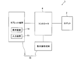
- FIG. 1 is a block diagram of a robot system 3 in which a teaching operation terminal 1 according to an embodiment of the present invention is used.
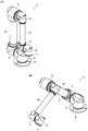
- FIG. 2 is a perspective view of the robot 2 shown in FIG.
- the teaching operation terminal 1 of this embodiment is a terminal used for teaching operation of the robot 2.
- This teaching operation terminal 1 is used in a robot system 3 including a robot 2.
- the robot system 3 includes a controller 4 that controls the robot 2 in addition to the teaching operation terminal 1 and the robot 2, and a tablet terminal (tablet PC) that is used together with the teaching operation terminal 1 when performing the teaching operation of the robot 2.
- the teaching operation terminal 1, the robot 2, and the tablet terminal 5 are electrically connected to the controller 4.
- Robot 2 is a vertical articulated robot. Specifically, the robot 2 is a 6-axis vertical articulated robot. As shown in FIG. 2, the robot 2 includes a support member 8 that constitutes the base end portion of the robot 2, six joint portions 9, two arms 10, and a tip member that constitutes the distal end portion of the robot 2. 11. The support member 8 is fixed to the floor on which the robot 2 is installed.
- the joint portion 9 includes a motor, a speed reducer coupled to the output shaft of the motor, and a case body in which the motor and the speed reducer are accommodated.
- the arm 10 is formed in an elongated cylindrical shape.
- the six joint portions 9 and the two arms 10 are configured so that the robot 2 can move from the directly-facing posture shown in FIG. 2A to the posture shown in FIG. And are connected.
- the joint portion 9 arranged on the most proximal side of the robot 2 is rotatably connected to the support member 8, and the joint portion 9 is rotatable with the vertical direction as the axis direction of rotation. Yes.
- the tip member 11 is rotatably connected to a joint portion 9 disposed on the most tip side of the robot 2.
- a predetermined end effector (not shown) can be attached to the tip member 11.
- the end effector is, for example, a gripping mechanism that grips a predetermined conveyance target or a processing tool that processes a predetermined processing target.
- the tablet terminal 5 includes a display device 14 such as a liquid crystal display and an input device 15 such as a touch panel or a keyboard.
- the tablet terminal 5 is connected to the controller 4 via, for example, a LAN cable.
- Software for teaching the robot 2 is installed in the tablet terminal 5, and the tablet terminal 5 is used together with the teaching operation terminal 1 when performing the teaching operation of the robot 2 as described above.
- the setting of the teaching operation of the robot 2, the change of the setting of the teaching operation, and the like are performed by the tablet terminal 5.
- the teaching operation terminal 1 of the present embodiment can be held with one hand by a worker who performs the teaching operation of the robot 2, and the worker can, for example, use a tablet terminal 5 placed on a predetermined table. Is operated with one hand while holding the teaching operation terminal 1 with the other hand.
- a teaching operation system 16 is configured by the teaching operation terminal 1 and the tablet terminal 5.
- FIG. 3 is a perspective view of the teaching operation terminal 1 shown in FIG.
- FIG. 4 is a side view of the teaching operation terminal 1 shown in FIG.
- FIG. 5 is a cross-sectional view of the teaching operation terminal 1 shown in FIG.
- the teaching operation terminal 1 enables the operation member 20 for operating the robot 2 and switching between a servo-on state where the operation member 20 can operate the robot 2 and a servo-off state where the operation member 20 cannot operate the robot 2.
- a switch 21 and an emergency stop switch 22 for emergency stop of the robot 2 are provided.
- the teaching operation terminal 1 includes a plurality of light emitting units 23 for notifying the state of the robot 2 and the state of the teaching operation terminal 1.
- the teaching operation terminal 1 of the present embodiment includes three light emitting units 23.
- the teaching operation terminal 1 includes a slide switch 24 as a first slide switch that switches a coordinate system when the robot 2 is operated by the operation member 20, and an operation location and an operation direction of the robot 2 operated by the operation member 20.
- a slide switch 25 serving as a second slide switch for switching at least one of them and a push button 26 for recording the current position of the robot 2 are provided.
- the teaching operation terminal 1 is provided with a buzzer 30 and a vibration motor 31 for notifying the abnormality of the robot 2 and two circuit boards 32 and 33.
- the buzzer 30, the vibration motor 31, and the circuit boards 32 and 33 are accommodated in the casing 27 of the teaching operation terminal 1. That is, the buzzer 30, the vibration motor 31, and the circuit boards 32 and 33 are built in the teaching operation terminal 1.
- the circuit board 32 of this embodiment is a first circuit board
- the circuit board 33 is a second circuit board.
- the operation member 20, the emergency stop switch 22, the slide switches 24 and 25, and the push button 26 are arranged on the front side of the teaching operation terminal 1. That is, the operation member 20, the emergency stop switch 22, the slide switches 24 and 25, and the push button 26 are disposed on the front side of the housing 27. Specifically, the operation unit 20a of the operation member 20 operated by the operator who performs the teaching operation of the robot 2, the operation unit 22a of the emergency stop switch 22, the operation unit 24a of the slide switch 24, and the operation unit 25a of the slide switch 25. The operation part 26 a of the push button 26 is disposed on the front side of the housing 27.
- the light emitting unit 23 is also arranged on the front side of the housing 27. Specifically, the light emitting unit 23 is arranged so that the light from the light emitting unit 23 can be seen from the front side of the housing 27.
- the enable switch 21 is disposed on the back side of the teaching operation terminal 1. That is, the enable switch 21 is disposed on the back side of the housing 27.
- an operation unit 21 a of the enable switch 21 operated by an operator who performs the teaching operation of the robot 2 is disposed on the back side of the housing 27.
- the base end portion of the housing 27 is a grip portion 27 a that is gripped by one hand of an operator who performs the teaching operation of the robot 2.
- the gripper 27a is gripped by the operator's middle finger, ring finger, little finger, and palm. Alternatively, the grip portion 27a is gripped by the operator's ring finger and little finger and the palm of the hand.
- the distal end portion of the housing 27 is a switch arrangement portion 27b where the operation member 20, the emergency stop switch 22 and the like are arranged.
- the housing 27 includes a gripping portion 27a and a switch placement portion 27b. A cable (not shown) of the teaching operation terminal 1 connected to the controller 4 is drawn from the base end of the housing 27.
- the front side (Z1 direction side in FIG. 4) of the teaching operation terminal 1 is referred to as “upper” side
- the opposite side (back side of the teaching operation terminal 1, Z2 direction side in FIG. 4) is referred to as “lower” side
- the base end side (X1 direction side in FIG. 4) of the teaching operation terminal 1 orthogonal to the vertical direction is the “rear” side
- the opposite side (tip side of the teaching operation terminal 1, X2 direction side in FIG. 4) is “ The front side.
- the Y direction in FIG. 4 orthogonal to the up and down direction and the left and right direction is referred to as “left and right direction”.
- the switch arrangement portion 27b protrudes obliquely downward and forward from the front upper end portion of the grip portion 27a.
- a bottom surface (lowermost surface) 27c of the switch placement portion 27b formed on the front end side of the switch placement portion 27b is a plane orthogonal to the vertical direction.
- a bottom surface (lowermost surface) 27d of the grip portion 27a formed on the rear end side of the grip portion 27a is a plane orthogonal to the vertical direction.
- the bottom surface 27c and the bottom surface 27d are disposed on the same plane.
- An upper surface (front surface of the teaching operation terminal 1) 27e of the grip portion 27a is formed in a convex curved surface, and a lower surface (surface on the back side of the teaching operation terminal 1) 27f of the grip portion 27a excluding the bottom surface 27d is The concave curved surface is formed.
- the upper surface 27e is formed in a convex curved surface having an arc shape when viewed from the left and right direction
- the lower surface 27f is formed in a concave curved surface having an arc shape when viewed from the left and right direction. Is formed.
- the curvature radius of the upper surface 27e is equal to the curvature radius of the lower surface 27f.
- the operation member 20 is a joystick.
- the main body 20b of the operation member 20 which is a joystick is mounted on the upper surface of the circuit board 32 as shown in FIG.
- the operation part 20a of the operation member 20 is disposed in front of the grip part 27a (that is, the front end side of the teaching operation terminal 1).
- the operation unit 20a is arranged at the center position in the left-right direction of the switch arrangement unit 27b.
- the axis L of the operation member 20 that is a joystick is orthogonal to the left-right direction.
- the axis L is inclined so as to go to the rear side as it goes down.
- the operation member 20 is operated by the operator's thumb. Specifically, the operation unit 20a is operated by the operator's thumb.
- the operation member 20 is operated in a mode in which the robot 2 is analog-operated by the operation member 20 (analog operation mode) and a mode in which the robot 2 is operated by frame operation (digital operation) by the operation member 20 (digital operation mode).
- the function of switching the operation mode of the member 20 is also achieved.
- the operation mode of the operation member 20 is switched from the analog operation mode to the digital operation mode, or from the digital operation mode to the analog operation mode.
- the operation portion 21a of the enable switch 21 protrudes obliquely downward and forward from the front lower end portion of the grip portion 27a.
- the operation unit 21 a is disposed at the center position in the left-right direction of the housing 27.
- the lower end of the operation unit 21a is disposed above the bottom surfaces 27c and 27d.
- the enable switch 21 is disposed so that the operation unit 21a is pushed obliquely upward and rearward.
- the operation portion 21 a is disposed on the axis L of the operation member 20.
- the angle ⁇ formed by the pressing direction of the enable switch 21 (that is, the pressing direction of the operation portion 21a, the direction indicated by the arrow V in FIG. 4) and the axis L is 60 ° or more and 90 ° or less. In this embodiment, the angle ⁇ is approximately 75 °.
- the enable switch 21 is operated by the operator's index finger (or middle finger). When the enable switch 21 is not pushed (that is, when the operation unit 21a is not pushed), the servo is turned off. When the operation unit 21a is pushed in the pushing direction V, the servo is turned on. When the operation unit 21a is strongly pushed in the pushing direction V, the servo-on state is switched to the servo-off state. That is, the enable switch 21 is a three-position enable switch.
- the operation unit 22a of the emergency stop switch 22 is disposed in front of the operation unit 20a of the operation member 20 (that is, the tip side of the teaching operation terminal 1).
- the operation unit 22a is arranged at the center position in the left-right direction of the switch arrangement unit 27b.
- the emergency stop switch 22 is arranged so that the operation portion 22a is pushed toward the diagonally lower rear side.
- the slide switch 24 is a three-contact slide switch, and the switch body 24b of the slide switch 24 is mounted on the upper surface of the circuit board 32 as shown in FIG.
- the slide switch 24 has a function of switching the coordinate system when the robot 2 is operated by the operation member 20 to any one of the three coordinate systems of the first coordinate system, the second coordinate system, and the third coordinate system.
- the first coordinate system is a coordinate system that represents the position of the tip member 11 using the rotational coordinates of the motors of the six joint portions 9 constituting the robot 2.
- the second coordinate system includes a coordinate in the vertical direction (z coordinate), a coordinate in the x direction orthogonal to the vertical direction (x coordinate), a coordinate in the y direction orthogonal to the vertical direction and the x direction (y coordinate),
- It is a coordinate system that represents the position of the tip member 11 using rotational coordinates.
- the third coordinate system is a coordinate system that represents the position of the end effector attached to the tip member 11 using the same six coordinates as the second coordinates.
- the slide switch 25 is a three-contact slide switch similar to the slide switch 24, and the switch body (not shown) of the slide switch 25 is mounted on the upper surface of the circuit board 32.
- the slide switch 25 has a function of switching at least one of the operation location and the operation direction of the robot 2 operated by the operation member 20. Specifically, when the coordinate system of the robot 2 is set to the first coordinate system, the slide switch 25 is disposed second from the proximal end side with the motor of the joint portion 9 disposed on the most proximal end side.
- the first mode in which the motor of the joint portion 9 is rotated by the operating member 20, the motor of the joint portion 9 arranged third from the base end side, and the motor of the joint portion 9 arranged fourth from the base end side Are rotated by the operating member 20, and the operating member 20 rotates the motor of the joint portion 9 arranged fifth from the proximal end side and the motor of the joint portion 9 arranged most distally. Switch to one of the three modes.
- the slide switch 25 is configured to operate the tip member 11 in the x direction and the y direction by the operation member 20 and the operation member.
- the second mode in which the distal end member 11 is operated in the z direction by 20 and the motor of the joint portion 9 disposed second from the distal end side is rotated, and the motor and the proximal end of the joint portion 9 disposed closest to the distal end side
- the mode is switched to one of the third mode in which the motor of the joint portion 9 arranged on the side is rotated by the operation member 20.
- the slide switch 25 uses the operation member 20 to operate the end effector in the x direction and the y direction, and the operation member 20.
- the second mode in which the end effector is operated in the z direction and the motor of the joint portion 9 disposed second from the distal end side is rotated, and the motor of the joint portion 9 disposed closest to the distal end side and the proximal end side
- the mode is switched to any one of the third mode in which the motor of the joint portion 9 to be arranged is rotated by the operation member 20.
- the button body 26b of the push button 26 is mounted on the upper surface of the circuit board 32 as shown in FIG. As described above, the push button 26 has a function of recording (teaching) the current position of the robot 2. When the operation unit 26 a of the push button 26 is pressed, the current position of the robot 2 is recorded.
- the push button 26 performs the function of recording (teaching) the current position of the robot 2, and when the operation unit 26a of the push button 26 is pressed, the current position of the robot 2 is recorded.
- the operation part 26a of the push button 26 is arranged in a state sandwiched between the operation part 24a of the slide switch 24 and the operation part 25a of the slide switch 25 in the left-right direction.
- the operation unit 24a of the slide switch 24, the operation unit 25a of the slide switch 25, and the operation unit 26a of the push button 26 are arranged in the switch arrangement unit 27b.
- the operation unit 26a is arranged at the center position in the left-right direction of the switch arrangement unit 27b.
- the operation unit 24a, the operation unit 25a, and the operation unit 26a are disposed between the operation unit 20a of the operation member 20 and the gripping unit 27a.
- the light emitting unit 23 includes a light source 23 a and a light guide member 23 b.
- the light source 23 a is an LED (light emitting diode) and is mounted on the upper surface of the circuit board 32.
- the light guide member 23 b is disposed on the upper side of the light source 23 a and functions to guide the light emitted from the light source 23 a to the front side of the housing 27.
- One of the three light emitting units 23 is lit in a predetermined color or blinks to indicate whether it is in a servo-on state or a servo-off state. 2 indicates that an overrun that operates out of the specified range has occurred, or indicates that an error has occurred.
- one of the light emitting units 23 is lit in a predetermined color or blinks, so that the operation mode of the operation member 20 is an analog operation mode or digital. Whether the operation mode is selected or that the slide positions of the slide switches 24 and 25 are unknown is displayed.
- the remaining one light emitting unit 23 displays the on / off state of the power source of the teaching operation terminal 1 by lighting in a predetermined color.
- the three light emitting units 23 are arranged so as to be adjacent in the left-right direction. Further, the three light emitting units 23 are arranged in the switch arrangement unit 27b. The light emitting unit 23 arranged at the center in the left-right direction among the three light emitting units 23 is arranged at the center position in the left-right direction of the switch arrangement unit 27b. Further, the three light emitting units 23 are disposed between the operation unit 20 a of the operation member 20 and the operation unit 22 a of the emergency stop switch 22. That is, the three light emitting units 23 are arranged on the front side (the tip side of the teaching operation terminal 1) of the operation member 20 with respect to the operation unit 20a.
- the buzzer 30 and the vibration motor 31 have a function of notifying the abnormality of the robot 2 as described above.
- the buzzer 30 generates an alarm when a predetermined error occurs during the teaching operation of the robot 2.
- the vibration motor 31 vibrates, for example, when an overrun occurs in which the robot 2 moves outside a specified range.
- the vibration motor 31 vibrates when the robot 2 comes into contact with other components disposed around the robot 2, for example.
- the buzzer 30 also sounds when the operation unit 26a of the push button 26 is pressed. That is, the buzzer 30 also sounds when the current position of the robot 2 is recorded. Moreover, the magnitude of the alarm generated by the buzzer 30 may be changed or the magnitude and intensity of vibration of the vibration motor 31 may be changed according to the type and degree of abnormality that has occurred in the robot 2.
- the circuit board 32 and the circuit board 33 are rigid boards such as a glass epoxy board, and are formed in a rectangular flat plate shape, for example.
- the circuit board 32 and the circuit board 33 are formed separately.
- the outer shape of the circuit board 32 is larger than the outer shape of the circuit board 33.
- the enable switch 21 is electrically connected to the circuit board 32 via a cable (not shown), and the emergency stop switch 22 is electrically connected via a cable (not shown).
- a buzzer 30 and a vibration motor 31 are mounted on the circuit board 33. Specifically, the buzzer 30 and the vibration motor 31 are mounted on the lower surface of the circuit board 33. In this embodiment, the vibration motor 31 is disposed in front of the buzzer 30.
- the circuit board 32 is fixed inside the housing 27.
- the circuit board 32 is disposed on the upper end side inside the housing 27. That is, the circuit board 32 is disposed on the front side of the teaching operation terminal 1.
- the rear end portion of the circuit board 32 is disposed inside the grip portion 27a, and most of the circuit board 32 excluding the rear end portion is disposed inside the switch arrangement portion 27b.
- the circuit board 32 formed in a flat plate shape is arranged so as to be parallel to the left-right direction. When viewed from the left-right direction, the circuit board 32 is inclined so as to go downward as it goes to the front side.
- the circuit board 33 is fixed inside the housing 27.
- the circuit board 33 is disposed on the lower end side inside the housing 27. That is, the circuit board 33 is arranged on the back side of the teaching operation terminal 1.
- the circuit board 33 is disposed inside the grip portion 27a. That is, the circuit board 33 is built in the holding part 27a. Specifically, the circuit board 33 is built in the grip portion 27 a on the back side of the teaching operation terminal 1. Further, since the circuit board 33 is built in the gripping part 27a, the buzzer 30 and the vibration motor 31 mounted on the circuit board 33 are also built in the gripping part 27a.
- the circuit board 33 formed in a flat plate shape is arranged so as to be parallel to the left-right direction. When viewed from the left-right direction, the circuit board 33 is inclined so as to go downward as it goes to the front side.
- the circuit board 32 and the circuit board 33 are disposed substantially in parallel.
- the base end portion of the casing 27 of the teaching operation terminal 1 is the grip portion 27 a that is gripped with one hand of the operator who performs the teaching operation of the robot 2.
- the operation unit 20a of the operation member 20 operated by the operator's thumb is arranged on the front side of the teaching operation terminal 1 and also on the front side of the teaching operation terminal 1 from the grasping unit 27a.
- the operation unit 21 a of the switch 21 is disposed on the back side of the teaching operation terminal 1 and is disposed on the axis L of the operation member 20.
- the angle ⁇ formed by the pressing direction V of the enable switch 21 and the axis L is 60 ° or more and 90 ° or less. Specifically, the angle ⁇ is approximately 75 °.
- an operator holding the grip portion 27a with one hand can easily press the operation portion 21a of the enable switch 21 with the index finger (or middle finger) of one hand holding the grip portion 27a.
- the operation portion 20a of the operation member 20 can be easily operated with the thumb of one hand holding the grip portion 27a. Therefore, in this embodiment, the operator who performs the teaching operation of the robot 2 can easily operate the teaching operation terminal 1 with one hand holding the teaching operation terminal 1.
- the operation part 22a of the emergency stop switch 22 is arranged on the distal end side of the teaching operation terminal 1 with respect to the operation part 20a of the operation member 20. Therefore, in this embodiment, the thumb of the operator who is operating the operation unit 20 a of the operation member 20 is less likely to come into contact with the operation unit 22 a of the emergency stop switch 22. Therefore, in this embodiment, it is possible to prevent erroneous operation of the emergency stop switch 22 when the teaching operation of the robot 2 is being performed.
- the operation unit 20a of the operation member 20 is operated to the operation unit of the emergency stop switch 22. It becomes possible to keep 22a away. Therefore, in this embodiment, the thumb of the operator who is operating the operation unit 20 a of the operation member 20 is less likely to come into contact with the operation unit 22 a of the emergency stop switch 22.
- the three light emitting units 23 are arranged on the distal end side of the teaching operation terminal 1 with respect to the operation unit 20a of the operation member 20. Therefore, in this embodiment, the light emitting unit 23 is not covered with the thumb of the operator who operates the operation unit 20a of the operation member 20. Therefore, in this embodiment, the operation member 20 can be operated while grasping the state of the robot 2 and the state of the teaching operation terminal 1 based on the light emission state of the light emitting unit 23.
- the operation unit 24a of the slide switch 24, the operation unit 25a of the slide switch 25, and the operation unit 26a of the push button 26 are disposed between the operation unit 20a of the operation member 20 and the gripping unit 27a. Therefore, in this embodiment, the operator who performs the teaching operation of the robot 2 can operate the operation unit 24a, the operation unit 25a, and the operation unit 26a using the thumb that operates the operation unit 20a of the operation member 20. Become. Therefore, in this embodiment, even if the slide switches 24 and 25 and the push button 26 are provided in the teaching operation terminal 1, the operator who performs the teaching operation of the robot 2 teaches with one hand holding the teaching operation terminal 1. The operation terminal 1 can be easily operated.
- the radius of curvature of the upper surface 27e of the grip portion 27a formed in a convex curved surface is equal to the radius of curvature of the lower surface 27f of the grip portion 27a formed in a concave curved surface. Therefore, in this embodiment, the operator can easily grip the grip portion 27a with one hand. Further, in this embodiment, when the teaching operation of the robot 2 is performed, the tablet terminal 5 installed with the robot teaching software is used together with the teaching operation terminal 1, so that the general-purpose tablet terminal 5 is used. The teaching operation of the robot 2 can be performed using
- a vibration motor 31 for notifying the abnormality of the robot 2 is built in the teaching operation terminal 1. Therefore, in the present embodiment, when an abnormality occurs in the robot 2 that is performing the teaching operation, the gripper 27a that is gripped by the operator who performs the teaching operation of the robot 2 by vibrating the vibration motor 31 built in the teaching operation terminal 1 is vibrated. Can be vibrated. Therefore, in this embodiment, when an abnormality occurs in the robot 2 that is performing the teaching operation, it is possible to promptly recognize the abnormality of the robot 2 by the operator who performs the teaching operation of the robot 2.
- the vibration motor 31 since the vibration motor 31 is built in the grip portion 27 a, the vibration motor 31 directly vibrates the grip portion 27 a gripped by the operator when an abnormality occurs in the robot 2 during the teaching operation. Can be made. Therefore, in this embodiment, when an abnormality occurs in the robot 2 during the teaching operation, the gripping unit 27a can be vibrated more greatly or more strongly by the vibration motor 31. As a result, in this embodiment, when an abnormality occurs in the robot 2 that is performing the teaching operation, it is possible for the operator to recognize the abnormality of the robot 2 more quickly.
- the buzzer 30 for notifying the abnormality of the robot 2 since the buzzer 30 for notifying the abnormality of the robot 2 is built in the teaching operation terminal 1, the buzzer 30 built in the teaching operation terminal 1 when an abnormality occurs in the robot 2 during the teaching operation. Can generate an alarm. Therefore, in this embodiment, when an abnormality occurs in the robot 2 that is performing the teaching operation, it is possible for the operator to recognize the abnormality of the robot 2 more quickly.
- the operation member 20, the enable switch 21, the emergency stop switch 22, the light emitting unit 23, the slide switches 24 and 25, and the push button 26 are electrically connected, the buzzer 30, and the vibration motor 31.
- the circuit board 33 to be mounted is formed separately. Therefore, in this embodiment, the vibration generated by the buzzer 30 and the vibration motor 31 is not easily transmitted to the circuit board 32. As a result, the vibration generated by the buzzer 30 and the vibration motor 31 is controlled by the operation member 20, the enable switch 21, and the emergency switch. Transmission to the stop switch 22, the light emitting unit 23, the slide switches 24 and 25, and the push button 26 becomes difficult. Therefore, in this embodiment, it is possible to reduce the influence of vibration generated by the buzzer 30 and the vibration motor 31 on the operation member 20, the light emitting unit 23, the slide switches 24 and 25, and the push button 26.
- the housing 27 can be reduced in size.
- the operation member 20 may be a cross key.
- the operation portion 21a of the enable switch 21 is arranged on the axis of the operation member 20 (that is, the axis of the cross key), and the pushing direction V of the enable switch 21 and the axis of the cross key are The formed angle ⁇ is 60 ° or more and 90 ° or less. Even in this case, the operator who performs the teaching operation of the robot 2 can easily operate the teaching operation terminal 1 with one hand holding the teaching operation terminal 1 in the same manner as described above. .
- the radius of curvature of the upper surface 27e of the grip portion 27a and the radius of curvature of the lower surface 27f of the grip portion 27a may be different. Further, at least one of the upper surface 27e and the lower surface 27f may be formed in a planar shape.
- the robot 2 may be a vertical articulated robot other than six axes, or a horizontal articulated robot. The robot 2 may be a robot other than the vertical articulated robot and the horizontal articulated robot.
- the operation unit 21 a of the enable switch 21 can be disposed on the left and right side surfaces of the teaching operation terminal 1. Further, using a teaching operation terminal formed in a substantially U shape (a U-shape) and having the same function as the teaching operation terminal 1 and a tablet terminal 5 fitted in the teaching operation terminal 1, the robot 2 It is also possible to perform a teaching operation.
- the circuit board 33 may be built in the switch arrangement portion 27b.
- the buzzer 30 and the vibration motor 31 may be built in the switch arrangement portion 27b.
- either the buzzer 30 or the vibration motor 31 may be built in the switch arrangement portion 27b.
- either one or both of the buzzer 30 and the vibration motor 31 may be mounted on the circuit board 32.
- the teaching operation terminal 1 may not include the buzzer 30.
- the operation member 20 may be a cross key.
- the robot 2 may be a vertical articulated robot other than six axes, or a horizontal articulated robot.
- the robot 2 may be a robot other than the vertical articulated robot and the horizontal articulated robot.
- the robot 2 includes the teaching operation terminal that is formed in a substantially U shape (U-shape) and has the same function as the teaching operation terminal 1 and the tablet terminal 5 that is fitted in the teaching operation terminal.
- the teaching operation may be performed.
- the teaching operation terminal 1 may include a display device such as a liquid crystal display and an input device such as a touch panel. In this case, the teaching operation terminal 1 may be held with both hands of the operator. In this case, the tablet terminal 5 becomes unnecessary.
Abstract
Provided is a teaching operation terminal for use in a robot teaching operation, with which an operator performing a robot teaching operation can easily carry out the operation using one hand that is gripping the teaching operation terminal, and which is capable of promptly allowing the operator to recognize when an abnormality of the robot has occurred. A teaching operation terminal 1 is provided with a grip portion 27a gripped by one hand of the operator, an operating member 20 which is operated by the thumb of the operator and activates the robot, and an enable switch 21. An operating portion 20a of the operating member 20 operated by the operator is disposed further to a distal end side of the teaching operation terminal 1 than the grip portion 27a and on a top side of the teaching operation terminal 1, and an operating portion 21a of the enable switch 21 operated by the operator is disposed on the reverse side of the teaching operation terminal 1 and on an axial line L of the operating member 20. A vibration motor 31 for notifying an abnormality of the robot is built into the teaching operation terminal 1.
Description
本発明は、ロボットの教示操作に使用される教示操作端末に関する。また、本発明は、この教示操作端末を備える教示操作システムに関する。
The present invention relates to a teaching operation terminal used for teaching operation of a robot. The present invention also relates to a teaching operation system including this teaching operation terminal.
従来、ロボットの教示操作に使用される教示操作端末が知られている(たとえば、特許文献1参照)。特許文献1に記載の教示操作端末は、LCDディスプレイと非常停止スイッチとイネーブルスイッチとを備えている。LCDディスプレイは、教示操作端末の表面中央に配置されている。非常停止スイッチは、LCDディスプレイの斜め上方に配置され、イネーブルスイッチは、教示操作端末の背面に配置されている。LCDディスプレイの左右の両側および下側には、複数のキー(スイッチ)が配置されている。また、イネーブルスイッチの近傍には、教示操作端末を把持するための把持部が設けられている。
Conventionally, a teaching operation terminal used for teaching operation of a robot is known (for example, see Patent Document 1). The teaching operation terminal described in Patent Document 1 includes an LCD display, an emergency stop switch, and an enable switch. The LCD display is arranged at the center of the surface of the teaching operation terminal. The emergency stop switch is disposed obliquely above the LCD display, and the enable switch is disposed on the back surface of the teaching operation terminal. A plurality of keys (switches) are arranged on both the left and right sides and the lower side of the LCD display. In addition, a grip portion for gripping the teaching operation terminal is provided in the vicinity of the enable switch.
特許文献1に記載の教示操作端末の場合、ロボットの教示操作を行う作業者は、一方の手で教示操作端末の把持部を把持するとともにイネーブルスイッチを押しながら、他方の手で各種のスイッチを操作してロボットを動作させている。すなわち、この教示操作端末の場合、作業者は、教示操作端末を把持している片手で教示操作端末を操作することはできない。そのため、この教示操作端末の場合、ロボットの教示操作を行う作業者の両手が塞がってしまう。
In the case of the teaching operation terminal described in Patent Document 1, an operator who performs the teaching operation of the robot grips the gripping portion of the teaching operation terminal with one hand and presses various switches with the other hand while pressing the enable switch. The robot is operated to operate. That is, in the case of this teaching operation terminal, the operator cannot operate the teaching operation terminal with one hand holding the teaching operation terminal. Therefore, in the case of this teaching operation terminal, both hands of the operator who performs the teaching operation of the robot are blocked.
そこで、本発明の第1の課題は、ロボットの教示操作に使用される教示操作端末において、ロボットの教示操作を行う作業者が、教示操作端末を把持している片手で容易に操作することが可能な教示操作端末を提供することにある。また、本発明は、この教示操作端末を備える教示操作システムを提供することにある。
Therefore, a first problem of the present invention is that an operator who performs the teaching operation of the robot can easily operate with one hand holding the teaching operation terminal in the teaching operation terminal used for the teaching operation of the robot. It is to provide a possible teaching operation terminal. Moreover, this invention is providing the teaching operation system provided with this teaching operation terminal.
また、特許文献1に記載された教示操作端末等の場合、一般に、教示操作中のロボットに異常が発生すると、LCDディスプレイ等の表示装置に異常が発生したことが表示され、ロボットの教示操作を行う作業者は、表示装置の表示を見て、教示操作中のロボットに異常が発生したことを認識する。そのため、特許文献1に記載された教示操作端末等では、たとえば、ロボットの教示操作を行う作業者が表示装置から目を離しているときにロボットに異常が発生すると、ロボットの異常を作業者に速やかに認識させることはできない。
In the case of the teaching operation terminal described in Patent Document 1, generally, when an abnormality occurs in the robot during the teaching operation, the fact that the abnormality has occurred is displayed on a display device such as an LCD display. The worker who performs the operation recognizes that an abnormality has occurred in the robot during the teaching operation by looking at the display on the display device. Therefore, in the teaching operation terminal or the like described in Patent Document 1, for example, if an abnormality occurs in the robot when the operator who performs the teaching operation of the robot keeps an eye on the display device, the abnormality of the robot is notified to the operator. It cannot be recognized promptly.
そこで、本発明の第2の課題は、ロボットの教示操作に使用される教示操作端末において、教示操作中のロボットに異常が発生したときに、ロボットの教示操作を行う作業者にロボットの異常を速やかに認識させることが可能な教示操作端末を提供することにある。
Accordingly, a second problem of the present invention is that when an abnormality occurs in the teaching operation terminal used in the teaching operation of the robot, an abnormality of the robot is notified to an operator who performs the teaching operation of the robot. An object of the present invention is to provide a teaching operation terminal that can be recognized quickly.
上記の第1の課題を解決するため、本発明の教示操作端末は、ロボットの教示操作に使用される教示操作端末において、ロボットの教示操作を行う作業者の片手で把持される把持部と、ジョイスティックまたは十字キーからなり作業者の親指で操作されるとともにロボットを動作させる操作部材と、操作部材によるロボットの動作が可能となるサーボオン状態と操作部材によるロボットの動作ができなくなるサーボオフ状態との切替を行うイネーブルスイッチとを備え、作業者によって操作される操作部材の操作部は、把持部よりも教示操作端末の先端側に配置され、操作部材の操作部が配置される側を教示操作端末の表側とすると、作業者によって操作されるイネーブルスイッチの操作部は、教示操作端末の裏側に配置されるとともに、ジョイスティックの軸線上または十字キーの軸線上に配置され、ジョイスティックの軸線または十字キーの軸線と、イネーブルスイッチの押込み方向とがなす角度は、60°以上90°以下となっていることを特徴とする。
In order to solve the above first problem, a teaching operation terminal of the present invention is a teaching operation terminal used for teaching operation of a robot, and a gripping unit gripped by one hand of an operator who performs teaching operation of the robot; Switching between an operation member consisting of a joystick or a cross key and operated by the operator's thumb and operating the robot, and a servo-on state in which the robot can be operated by the operation member and a servo-off state in which the robot cannot be operated by the operation member An operation switch of an operation member operated by an operator is disposed closer to the distal end side of the teaching operation terminal than the gripping portion, and a side on which the operation unit of the operation member is disposed is arranged on the teaching operation terminal. If the front side, the operation part of the enable switch operated by the operator is arranged on the back side of the teaching operation terminal, It is arranged on the axis of the joystick or the axis of the cross key, and the angle formed by the axis of the joystick or the cross key and the pushing direction of the enable switch is 60 ° or more and 90 ° or less. .
本発明の教示操作端末は、ロボットの教示操作を行う作業者の片手で把持される把持部を備えている。また、本発明では、作業者の親指で操作される操作部材の操作部は、把持部より教示操作端末の先端側に配置されるとともに教示操作端末の表側に配置され、イネーブルスイッチの操作部は、教示操作端末の裏側に配置されるとともにジョイスティックの軸線上または十字キーの軸線上に配置されている。さらに、本発明では、ジョイスティックの軸線または十字キーの軸線と、イネーブルスイッチの押込み方向とがなす角度は、60°以上90°以下となっている。
The teaching operation terminal of the present invention includes a gripping unit that is gripped by one hand of an operator who performs teaching operation of a robot. In the present invention, the operation portion of the operation member operated by the operator's thumb is disposed on the front side of the teaching operation terminal from the grip portion and on the front side of the teaching operation terminal, and the operation portion of the enable switch is And arranged on the back side of the teaching operation terminal and on the axis of the joystick or the axis of the cross key. Furthermore, in the present invention, the angle formed between the axis of the joystick or the axis of the cross key and the pressing direction of the enable switch is 60 ° or more and 90 ° or less.
そのため、本発明では、把持部を片手で把持している作業者が、把持部を把持している片手の人差し指や中指等でイネーブルスイッチの操作部を容易に押すことが可能になるとともに、把持部を把持している片手の親指で操作部材の操作部を容易に操作することが可能になる。したがって、本発明では、ロボットの教示操作を行う作業者が、教示操作端末を把持している片手で教示操作端末を容易に操作することが可能になる。
Therefore, according to the present invention, an operator holding the grip part with one hand can easily push the operation part of the enable switch with the index finger or middle finger of one hand holding the grip part, It is possible to easily operate the operation portion of the operation member with the thumb of one hand holding the portion. Therefore, according to the present invention, the operator who performs the teaching operation of the robot can easily operate the teaching operation terminal with one hand holding the teaching operation terminal.
本発明において、ジョイスティックの軸線または十字キーの軸線と、イネーブルスイッチの押込み方向とがなす角度は、略75°となっていることが好ましい。このように構成すると、把持部を片手で把持している作業者が、把持部を把持している片手の人差し指や中指等でイネーブルスイッチをより容易に押すことが可能になるとともに、把持部を把持している片手の親指で操作部材をより容易に操作することが可能になる。したがって、ロボットの教示操作を行う作業者が、教示操作端末を把持している片手で教示操作端末をより容易に操作することが可能になる。
In the present invention, it is preferable that the angle formed by the axis line of the joystick or the cross key and the pushing direction of the enable switch is approximately 75 °. With this configuration, an operator holding the grip part with one hand can more easily press the enable switch with the index finger or middle finger of one hand holding the grip part, and It becomes possible to more easily operate the operation member with the thumb of one hand holding. Therefore, the operator who performs the teaching operation of the robot can more easily operate the teaching operation terminal with one hand holding the teaching operation terminal.
本発明において、教示操作端末は、ロボットを非常停止させる非常停止スイッチを備え、作業者によって操作される非常停止スイッチの操作部は、操作部材の操作部よりも教示操作端末の先端側に配置されていることが好ましい。このように構成すると、操作部材の操作部を操作している作業者の親指が非常停止スイッチの操作部に接触しにくくなる。したがって、ロボットの教示操作を行っているときの、非常停止スイッチの誤操作を防止することが可能になる。
In the present invention, the teaching operation terminal is provided with an emergency stop switch for emergency stop of the robot, and the operation part of the emergency stop switch operated by the operator is arranged on the tip side of the teaching operation terminal with respect to the operation part of the operation member. It is preferable. If comprised in this way, it will become difficult for the operator's thumb who is operating the operation part of an operation member to contact the operation part of an emergency stop switch. Therefore, it is possible to prevent erroneous operation of the emergency stop switch when performing the teaching operation of the robot.
本発明において、教示操作端末は、ロボットの状態および教示操作端末の状態の少なくともいずれか一方を知らせるための発光部を備え、発光部は、操作部材の操作部と非常停止スイッチの操作部との間に配置されていることが好ましい。このように構成すると、操作部材の操作部を操作する作業者の親指によって発光部が覆われるのを防止することが可能になる。したがって、発光部の発光状態に基づいて、ロボットの状態や教示操作端末の状態を把握しながら、操作部材を操作することが可能になる。また、このように構成すると、操作部材の操作部から非常停止スイッチの操作部を遠ざけることが可能になる。したがって、操作部材の操作部を操作している作業者の親指が非常停止スイッチの操作部により接触しにくくなる。
In the present invention, the teaching operation terminal includes a light emitting unit for informing at least one of the state of the robot and the state of the teaching operation terminal, and the light emitting unit includes an operation unit of the operation member and an operation unit of the emergency stop switch. It is preferable to arrange | position between. If comprised in this way, it will become possible to prevent that a light emission part is covered with the thumb of the operator who operates the operation part of an operation member. Therefore, the operation member can be operated while grasping the state of the robot and the state of the teaching operation terminal based on the light emission state of the light emitting unit. Moreover, if comprised in this way, it will become possible to keep the operation part of an emergency stop switch away from the operation part of an operation member. Therefore, it is difficult for the operator's thumb operating the operating part of the operating member to come into contact with the operating part of the emergency stop switch.
本発明において、教示操作端末は、操作部材によってロボットを動作させる際の座標系を切り替える第1のスライドスイッチと、操作部材によって動作するロボットの動作箇所および動作方向の少なくともいずれか一方を切り替える第2のスライドスイッチと、ロボットの現在位置を記録するための押ボタンとを備え、作業者によって操作される第1のスライドスイッチの操作部、第2のスライドスイッチの操作部および押ボタン操作部は、操作部材の操作部と把持部との間に配置されていることが好ましい。
In the present invention, the teaching operation terminal includes a first slide switch that switches a coordinate system when the robot is operated by the operation member, and a second switch that switches at least one of the operation location and the operation direction of the robot operated by the operation member. The first slide switch operating unit, the second slide switch operating unit, and the push button operating unit operated by an operator are provided with a slide switch and a push button for recording the current position of the robot. It is preferable that the operation member is disposed between the operation portion and the grip portion.
このように構成すると、ロボットの教示操作を行う作業者は、操作部材の操作部を操作する親指を使って、第1のスライドスイッチの操作部、第2のスライドスイッチの操作部および押ボタンの操作部を操作することが可能になる。したがって、第1のスライドスイッチ、第2のスライドスイッチおよび押ボタンが教示操作端末に設けられていても、ロボットの教示操作を行う作業者は、教示操作端末を把持している片手で教示操作端末を容易に操作することが可能になる。
With this configuration, the operator who performs the teaching operation of the robot uses the thumb that operates the operation unit of the operation member to operate the operation unit of the first slide switch, the operation unit of the second slide switch, and the push button. The operation unit can be operated. Therefore, even if the first slide switch, the second slide switch, and the push button are provided in the teaching operation terminal, the operator who performs the teaching operation of the robot can use the teaching operation terminal with one hand holding the teaching operation terminal. Can be easily operated.
本発明において、把持部の、教示操作端末の表側の面は、凸曲面状に形成され、把持部の、教示操作端末の裏側の面は、凹曲面状に形成され、把持部の、教示操作端末の表側の面の曲率半径と、把持部の、教示操作端末の裏側の面の曲率半径とが等しくなっていることが好ましい。このように構成すると、作業者は片手で把持部を把持しやすくなる。
In the present invention, the front side surface of the teaching operation terminal of the gripping part is formed in a convex curved surface, and the back side surface of the gripping operation terminal is formed in a concave curved surface, and the teaching operation of the gripping unit is performed. It is preferable that the curvature radius of the surface on the front side of the terminal is equal to the curvature radius of the surface on the back side of the teaching operation terminal of the grip portion. If comprised in this way, it will become easy for an operator to hold | grip a holding part with one hand.
本発明の教示操作端末は、表示装置および入力装置を有するとともにロボットの教示用のソフトウエアがインストールされたタブレット端末を備える教示操作システムに用いることができる。この教示操作システムでは、ロボットの教示操作を行う作業者が、教示操作端末を把持している片手で教示操作端末を容易に操作することが可能になる。また、この教示操作システムでは、ロボット教示用のソフトウエアがインストールされた汎用のタブレット端末を利用して、ロボットの教示操作を行うことが可能になる。
The teaching operation terminal of the present invention can be used in a teaching operation system including a tablet terminal having a display device and an input device and installed with robot teaching software. In this teaching operation system, an operator who performs the teaching operation of the robot can easily operate the teaching operation terminal with one hand holding the teaching operation terminal. Further, in this teaching operation system, it becomes possible to perform teaching operation of the robot using a general-purpose tablet terminal in which software for robot teaching is installed.
上記の第2の課題を解決するため、本発明の教示操作端末は、ロボットの教示操作に使用される教示操作端末において、ロボットの教示操作を行う作業者に把持される把持部を備えるとともに、ロボットの異常を知らせる振動モータが内蔵されていることを特徴とする。
In order to solve the second problem, a teaching operation terminal according to the present invention includes a gripping unit that is gripped by an operator who performs a teaching operation of the robot in the teaching operation terminal used for the teaching operation of the robot, It is characterized by a built-in vibration motor that notifies the robot of abnormalities.
本発明の教示操作端末には、ロボットの異常を知らせる振動モータが内蔵されている。そのため、本発明では、教示操作中のロボットに異常が発生したときに、教示操作端末に内蔵された振動モータを振動させて、ロボットの教示操作を行う作業者が把持する把持部を振動させることが可能になる。したがって、本発明では、教示操作中のロボットに異常が発生したときに、ロボットの教示操作を行う作業者にロボットの異常を速やかに認識させることが可能になる。
The teaching operation terminal of the present invention has a built-in vibration motor that notifies the abnormality of the robot. Therefore, according to the present invention, when an abnormality occurs in the robot during the teaching operation, the vibration motor built in the teaching operation terminal is vibrated to vibrate the gripping portion held by the operator who performs the robot teaching operation. Is possible. Therefore, according to the present invention, when an abnormality occurs in the robot during the teaching operation, it is possible to promptly recognize the abnormality of the robot by the operator who performs the teaching operation of the robot.
本発明において、振動モータは、把持部に内蔵されていることが好ましい。このように構成すると、教示操作中のロボットに異常が発生したときに、作業者が把持する把持部を振動モータによって直接的に振動させることが可能になる。したがって、教示操作中のロボットに異常が発生したときに、振動モータによって把持部をより大きく振動させたり、より強く振動させたりすることが可能になる。その結果、教示操作中のロボットに異常が発生したときに、作業者にロボットの異常をより速やかに認識させることが可能になる。
In the present invention, the vibration motor is preferably built in the gripping portion. If comprised in this way, when abnormality will generate | occur | produce in the robot in teaching operation, it will become possible to vibrate the holding part which an operator holds directly with a vibration motor. Therefore, when an abnormality occurs in the robot during the teaching operation, the gripping portion can be vibrated more greatly or more strongly by the vibration motor. As a result, when an abnormality occurs in the robot during the teaching operation, it becomes possible for the operator to recognize the abnormality of the robot more quickly.
本発明において、教示操作端末には、ロボットの異常を知らせるブザーが内蔵されていることが好ましい。このように構成すると、教示操作中のロボットに異常が発生したときに、教示操作端末に内蔵されたブザーで警報を発生させることが可能になる。したがって、教示操作中のロボットに異常が発生したときに、作業者にロボットの異常をより速やかに認識させることが可能になる。
In the present invention, it is preferable that the teaching operation terminal has a built-in buzzer for notifying the abnormality of the robot. If comprised in this way, when abnormality will generate | occur | produce in the robot in teaching operation, it will become possible to generate an alarm with the buzzer built in the teaching operation terminal. Therefore, when an abnormality occurs in the robot during the teaching operation, it is possible to make the operator recognize the abnormality of the robot more quickly.
本発明において、教示操作端末は、ロボットを動作させる操作部材と、操作部材によるロボットの動作が可能となるサーボオン状態と操作部材によるロボットの動作ができなくなるサーボオフ状態との切替を行うイネーブルスイッチと、ロボットを非常停止させる非常停止スイッチと、操作部材、イネーブルスイッチおよび非常停止スイッチが電気的に接続される第1の回路基板と、第1の回路基板と別体で形成されるとともに振動モータが実装される第2の回路基板とを備えていることが好ましい。
In the present invention, the teaching operation terminal includes an operation member for operating the robot, an enable switch for switching between a servo-on state in which the robot can be operated by the operation member and a servo-off state in which the operation of the robot by the operation member is disabled. An emergency stop switch for emergency stop of the robot, a first circuit board to which the operation member, the enable switch and the emergency stop switch are electrically connected, and a vibration motor are formed separately from the first circuit board. The second circuit board is preferably provided.
このように構成すると、操作部材、イネーブルスイッチおよび非常停止スイッチが電気的に接続される第1の回路基板に、振動モータで発生する振動が伝達されにくくなる。したがって、振動モータで発生する振動が操作部材等に及ぼす影響を低減することが可能になる。また、このように構成すると、第1の回路基板と第2の回路基板とが一体で形成されている場合と比較して、教示操作端末の内部に第1の回路基板と第2の回路基板とを配置しやすくなる。
This configuration makes it difficult for vibration generated by the vibration motor to be transmitted to the first circuit board to which the operation member, the enable switch, and the emergency stop switch are electrically connected. Accordingly, it is possible to reduce the influence of vibration generated by the vibration motor on the operation member and the like. Also, with this configuration, the first circuit board and the second circuit board are provided in the teaching operation terminal as compared with the case where the first circuit board and the second circuit board are integrally formed. And will be easier to place.
本発明において、教示操作端末は、たとえば、操作部材によってロボットを動作させる際の座標系を切り替える第1のスライドスイッチと、操作部材によって動作するロボットの動作箇所および動作方向の少なくともいずれか一方を切り替える第2のスライドスイッチと、ロボットの現在位置を記録するための押ボタンとを備え、第1のスライドスイッチ、第2のスライドスイッチおよび押ボタンは、第1の回路基板に電気的に接続されている。
In the present invention, the teaching operation terminal switches, for example, at least one of the first slide switch for switching the coordinate system when the robot is operated by the operation member, and the operation location and the operation direction of the robot operated by the operation member. A second slide switch and a push button for recording the current position of the robot, wherein the first slide switch, the second slide switch, and the push button are electrically connected to the first circuit board; Yes.
この場合には、第1のスライドスイッチ、第2のスライドスイッチおよび押ボタンが電気的に接続される第1の回路基板に、振動モータで発生する振動が伝達されにくくなる。したがって、振動モータで発生する振動が、第1のスライドスイッチ、第2のスライドスイッチおよび押ボタンに及ぼす影響を低減することが可能になる。
In this case, the vibration generated by the vibration motor is not easily transmitted to the first circuit board to which the first slide switch, the second slide switch, and the push button are electrically connected. Therefore, it is possible to reduce the influence of the vibration generated by the vibration motor on the first slide switch, the second slide switch, and the push button.
本発明において、第2の回路基板は、把持部に内蔵されていることが好ましい。このように構成すると、教示操作中のロボットに異常が発生したときに、作業者が把持する把持部を振動モータによって直接的に振動させることが可能になる。したがって、教示操作中のロボットに異常が発生したときに、振動モータによって把持部をより大きく振動させたり、より強く振動させたりすることが可能になる。その結果、教示操作中のロボットに異常が発生したときに、作業者にロボットの異常をより速やかに認識させることが可能になる。
In the present invention, it is preferable that the second circuit board is built in the holding part. If comprised in this way, when abnormality will generate | occur | produce in the robot in teaching operation, it will become possible to vibrate the holding part which an operator holds directly with a vibration motor. Therefore, when an abnormality occurs in the robot during the teaching operation, the gripping portion can be vibrated more greatly or more strongly by the vibration motor. As a result, when an abnormality occurs in the robot during the teaching operation, it becomes possible for the operator to recognize the abnormality of the robot more quickly.
本発明において、教示操作端末には、ロボットの異常を知らせるブザーが内蔵され、ブザーは、第2の回路基板に実装されていることが好ましい。このように構成すると、教示操作中のロボットに異常が発生したときに、教示操作端末に内蔵されたブザーで警報を発生させることが可能になる。したがって、教示操作中のロボットに異常が発生したときに、作業者にロボットの異常をより速やかに認識させることが可能になる。また、このように構成すると、第1の回路基板に、ブザーで発生する振動が伝達されにくくなる。したがって、ブザーで発生する振動が操作部材等に及ぼす影響を低減することが可能になる。
In the present invention, it is preferable that the teaching operation terminal has a built-in buzzer for notifying the abnormality of the robot, and the buzzer is mounted on the second circuit board. If comprised in this way, when abnormality will generate | occur | produce in the robot in teaching operation, it will become possible to generate an alarm with the buzzer built in the teaching operation terminal. Therefore, when an abnormality occurs in the robot during the teaching operation, it is possible to make the operator recognize the abnormality of the robot more quickly. Also, with this configuration, vibration generated by the buzzer is not easily transmitted to the first circuit board. Therefore, it is possible to reduce the influence of vibration generated by the buzzer on the operation member and the like.
以上のように、本発明では、ロボットの教示操作を行う作業者が、教示操作端末を把持している片手で教示操作端末を容易に操作することが可能になる。また、本発明の教示操作端末では、教示操作中のロボットに異常が発生したときに、ロボットの教示操作を行う作業者にロボットの異常を速やかに認識させることが可能になる。
As described above, according to the present invention, the operator who performs the teaching operation of the robot can easily operate the teaching operation terminal with one hand holding the teaching operation terminal. Further, the teaching operation terminal of the present invention makes it possible to promptly recognize the abnormality of the robot by the operator who performs the teaching operation of the robot when the abnormality occurs in the robot during the teaching operation.
以下、図面を参照しながら、本発明の実施の形態を説明する。
Hereinafter, embodiments of the present invention will be described with reference to the drawings.
(ロボットシステムの概略構成)
図1は、本発明の実施の形態にかかる教示操作端末1が使用されるロボットシステム3のブロック図である。図2は、図1に示すロボット2の斜視図である。 (Schematic configuration of the robot system)
FIG. 1 is a block diagram of a robot system 3 in which ateaching operation terminal 1 according to an embodiment of the present invention is used. FIG. 2 is a perspective view of the robot 2 shown in FIG.
図1は、本発明の実施の形態にかかる教示操作端末1が使用されるロボットシステム3のブロック図である。図2は、図1に示すロボット2の斜視図である。 (Schematic configuration of the robot system)
FIG. 1 is a block diagram of a robot system 3 in which a
本形態の教示操作端末1は、ロボット2の教示操作に使用される端末である。この教示操作端末1は、ロボット2を備えるロボットシステム3で使用される。ロボットシステム3は、教示操作端末1およびロボット2に加えて、ロボット2を制御するコントローラ4と、ロボット2の教示操作を行う際に教示操作端末1と一緒に使用されるタブレット端末(タブレットPC)5とを備えている。教示操作端末1、ロボット2およびタブレット端末5は、コントローラ4に電気的に接続されている。
The teaching operation terminal 1 of this embodiment is a terminal used for teaching operation of the robot 2. This teaching operation terminal 1 is used in a robot system 3 including a robot 2. The robot system 3 includes a controller 4 that controls the robot 2 in addition to the teaching operation terminal 1 and the robot 2, and a tablet terminal (tablet PC) that is used together with the teaching operation terminal 1 when performing the teaching operation of the robot 2. And 5. The teaching operation terminal 1, the robot 2, and the tablet terminal 5 are electrically connected to the controller 4.
ロボット2は、垂直多関節ロボットである。具体的には、ロボット2は、6軸の垂直多関節ロボットである。ロボット2は、図2に示すように、ロボット2の基端部分を構成する支持部材8と、6個の関節部9と、2本のアーム10と、ロボット2の先端部分を構成する先端部材11とを備えている。支持部材8は、ロボット2が設置される床面に固定されている。関節部9は、モータと、モータの出力軸に連結される減速機と、モータおよび減速機が収容されるケース体とを備えている。アーム10は、細長い円筒状に形成されている。
Robot 2 is a vertical articulated robot. Specifically, the robot 2 is a 6-axis vertical articulated robot. As shown in FIG. 2, the robot 2 includes a support member 8 that constitutes the base end portion of the robot 2, six joint portions 9, two arms 10, and a tip member that constitutes the distal end portion of the robot 2. 11. The support member 8 is fixed to the floor on which the robot 2 is installed. The joint portion 9 includes a motor, a speed reducer coupled to the output shaft of the motor, and a case body in which the motor and the speed reducer are accommodated. The arm 10 is formed in an elongated cylindrical shape.
ロボット2では、たとえば、図2(A)に示す正対姿勢から図2(B)に示す姿勢へのロボット2の動作が可能となるように、6個の関節部9と2本のアーム10とが連結されている。ロボット2の最も基端側に配置される関節部9は、支持部材8に回動可能に連結されており、この関節部9は、上下方向を回動の軸方向として回動可能となっている。先端部材11は、ロボット2の最も先端側に配置される関節部9に回動可能に連結されている。先端部材11には、所定のエンドエフェクタ(図示省略)が取付可能となっている。このエンドエフェクタは、たとえば、所定の搬送対象物を把持する把持機構や、所定の加工対象物を加工する加工工具である。
In the robot 2, for example, the six joint portions 9 and the two arms 10 are configured so that the robot 2 can move from the directly-facing posture shown in FIG. 2A to the posture shown in FIG. And are connected. The joint portion 9 arranged on the most proximal side of the robot 2 is rotatably connected to the support member 8, and the joint portion 9 is rotatable with the vertical direction as the axis direction of rotation. Yes. The tip member 11 is rotatably connected to a joint portion 9 disposed on the most tip side of the robot 2. A predetermined end effector (not shown) can be attached to the tip member 11. The end effector is, for example, a gripping mechanism that grips a predetermined conveyance target or a processing tool that processes a predetermined processing target.
タブレット端末5は、液晶ディスプレイ等の表示装置14と、タッチパネルまたはキーボード等の入力装置15とを備えている。このタブレット端末5は、たとえば、LANケーブルを介してコントローラ4に接続されている。タブレット端末5には、ロボット2の教示用のソフトウエアがインストールされており、タブレット端末5は、上述のように、ロボット2の教示操作を行う際に教示操作端末1と一緒に使用される。ロボット2の教示操作の設定や教示操作の設定の変更等は、タブレット端末5で行われる。
The tablet terminal 5 includes a display device 14 such as a liquid crystal display and an input device 15 such as a touch panel or a keyboard. The tablet terminal 5 is connected to the controller 4 via, for example, a LAN cable. Software for teaching the robot 2 is installed in the tablet terminal 5, and the tablet terminal 5 is used together with the teaching operation terminal 1 when performing the teaching operation of the robot 2 as described above. The setting of the teaching operation of the robot 2, the change of the setting of the teaching operation, and the like are performed by the tablet terminal 5.
本形態の教示操作端末1は、ロボット2の教示操作を行う作業者が片手で把持することが可能となっており、作業者は、たとえば、所定の台の上に載置されたタブレット端末5を一方の手で操作しながら、他方の手で教示操作端末1を把持して操作する。本形態では、教示操作端末1とタブレット端末5とによって、教示操作システム16が構成されている。
The teaching operation terminal 1 of the present embodiment can be held with one hand by a worker who performs the teaching operation of the robot 2, and the worker can, for example, use a tablet terminal 5 placed on a predetermined table. Is operated with one hand while holding the teaching operation terminal 1 with the other hand. In this embodiment, a teaching operation system 16 is configured by the teaching operation terminal 1 and the tablet terminal 5.
(教示操作端末の構成)
図3は、図1に示す教示操作端末1の斜視図である。図4は、図3に示す教示操作端末1の側面図である。図5は、図3に示す教示操作端末1の断面図である。 (Configuration of teaching operation terminal)
FIG. 3 is a perspective view of theteaching operation terminal 1 shown in FIG. FIG. 4 is a side view of the teaching operation terminal 1 shown in FIG. FIG. 5 is a cross-sectional view of the teaching operation terminal 1 shown in FIG.
図3は、図1に示す教示操作端末1の斜視図である。図4は、図3に示す教示操作端末1の側面図である。図5は、図3に示す教示操作端末1の断面図である。 (Configuration of teaching operation terminal)
FIG. 3 is a perspective view of the
教示操作端末1は、ロボット2を動作させる操作部材20と、操作部材20によるロボット2の動作が可能となるサーボオン状態と操作部材20によるロボット2の動作ができなくなるサーボオフ状態との切替を行うイネーブルスイッチ21と、ロボット2を非常停止させる非常停止スイッチ22とを備えている。また、教示操作端末1は、ロボット2の状態および教示操作端末1の状態を知らせるための複数の発光部23を備えている。本形態の教示操作端末1は、3個の発光部23を備えている。
The teaching operation terminal 1 enables the operation member 20 for operating the robot 2 and switching between a servo-on state where the operation member 20 can operate the robot 2 and a servo-off state where the operation member 20 cannot operate the robot 2. A switch 21 and an emergency stop switch 22 for emergency stop of the robot 2 are provided. In addition, the teaching operation terminal 1 includes a plurality of light emitting units 23 for notifying the state of the robot 2 and the state of the teaching operation terminal 1. The teaching operation terminal 1 of the present embodiment includes three light emitting units 23.
また、教示操作端末1は、操作部材20によってロボット2を動作させる際の座標系を切り替える第1のスライドスイッチとしてのスライドスイッチ24と、操作部材20によって動作するロボット2の動作箇所および動作方向の少なくともいずれか一方を切り替える第2のスライドスイッチとしてのスライドスイッチ25と、ロボット2の現在位置を記録するための押ボタン26とを備えている。
In addition, the teaching operation terminal 1 includes a slide switch 24 as a first slide switch that switches a coordinate system when the robot 2 is operated by the operation member 20, and an operation location and an operation direction of the robot 2 operated by the operation member 20. A slide switch 25 serving as a second slide switch for switching at least one of them and a push button 26 for recording the current position of the robot 2 are provided.
さらに、教示操作端末1は、ロボット2の異常を知らせるブザー30および振動モータ31と、2枚の回路基板32、33とを備えている。ブザー30、振動モータ31および回路基板32、33は、教示操作端末1の筐体27に収容されている。すなわち、ブザー30、振動モータ31および回路基板32、33は、教示操作端末1に内蔵されている。本形態の回路基板32は、第1の回路基板であり、回路基板33は、第2の回路基板である。
Further, the teaching operation terminal 1 is provided with a buzzer 30 and a vibration motor 31 for notifying the abnormality of the robot 2 and two circuit boards 32 and 33. The buzzer 30, the vibration motor 31, and the circuit boards 32 and 33 are accommodated in the casing 27 of the teaching operation terminal 1. That is, the buzzer 30, the vibration motor 31, and the circuit boards 32 and 33 are built in the teaching operation terminal 1. The circuit board 32 of this embodiment is a first circuit board, and the circuit board 33 is a second circuit board.
操作部材20、非常停止スイッチ22、スライドスイッチ24、25および押ボタン26は、教示操作端末1の表側に配置されている。すなわち、操作部材20、非常停止スイッチ22、スライドスイッチ24、25および押ボタン26は、筐体27の表側に配置されている。具体的には、ロボット2の教示操作を行う作業者によって操作される操作部材20の操作部20a、非常停止スイッチ22の操作部22a、スライドスイッチ24の操作部24a、スライドスイッチ25の操作部25aおよび押ボタン26の操作部26aが筐体27の表側に配置されている。
The operation member 20, the emergency stop switch 22, the slide switches 24 and 25, and the push button 26 are arranged on the front side of the teaching operation terminal 1. That is, the operation member 20, the emergency stop switch 22, the slide switches 24 and 25, and the push button 26 are disposed on the front side of the housing 27. Specifically, the operation unit 20a of the operation member 20 operated by the operator who performs the teaching operation of the robot 2, the operation unit 22a of the emergency stop switch 22, the operation unit 24a of the slide switch 24, and the operation unit 25a of the slide switch 25. The operation part 26 a of the push button 26 is disposed on the front side of the housing 27.
また、発光部23も、筐体27の表側に配置されている。具体的には、筐体27の表側から発光部23の光が見えるように発光部23が配置されている。一方、イネーブルスイッチ21は、教示操作端末1の裏側に配置されている。すなわち、イネーブルスイッチ21は、筐体27の裏側に配置されている。具体的には、ロボット2の教示操作を行う作業者によって操作されるイネーブルスイッチ21の操作部21aが筐体27の裏側に配置されている。
The light emitting unit 23 is also arranged on the front side of the housing 27. Specifically, the light emitting unit 23 is arranged so that the light from the light emitting unit 23 can be seen from the front side of the housing 27. On the other hand, the enable switch 21 is disposed on the back side of the teaching operation terminal 1. That is, the enable switch 21 is disposed on the back side of the housing 27. Specifically, an operation unit 21 a of the enable switch 21 operated by an operator who performs the teaching operation of the robot 2 is disposed on the back side of the housing 27.
筐体27の基端部分は、ロボット2の教示操作を行う作業者の片手で把持される把持部27aとなっている。把持部27aは、作業者の中指、薬指および小指と、手のひらとによって把持される。あるいは、把持部27aは、作業者の薬指および小指と、手のひらとによって把持される。筐体27の先端部分は、操作部材20および非常停止スイッチ22等が配置されるスイッチ配置部27bとなっている。筐体27は、把持部27aとスイッチ配置部27bとによって構成されている。コントローラ4に接続される教示操作端末1のケーブル(図示省略)は、筐体27の基端から引き出されている。
The base end portion of the housing 27 is a grip portion 27 a that is gripped by one hand of an operator who performs the teaching operation of the robot 2. The gripper 27a is gripped by the operator's middle finger, ring finger, little finger, and palm. Alternatively, the grip portion 27a is gripped by the operator's ring finger and little finger and the palm of the hand. The distal end portion of the housing 27 is a switch arrangement portion 27b where the operation member 20, the emergency stop switch 22 and the like are arranged. The housing 27 includes a gripping portion 27a and a switch placement portion 27b. A cable (not shown) of the teaching operation terminal 1 connected to the controller 4 is drawn from the base end of the housing 27.
以下の説明では、教示操作端末1の表側(図4のZ1方向側)を「上」側とし、その反対側(教示操作端末1の裏側、図4のZ2方向側)を「下」側とし、上下方向に直交する教示操作端末1の基端側(図4のX1方向側)を「後ろ」側とし、その反対側(教示操作端末1の先端側、図4のX2方向側)を「前」側とする。また、上下方向と左右方向とに直交する図4のY方向を「左右方向」とする。
In the following description, the front side (Z1 direction side in FIG. 4) of the teaching operation terminal 1 is referred to as “upper” side, and the opposite side (back side of the teaching operation terminal 1, Z2 direction side in FIG. 4) is referred to as “lower” side. The base end side (X1 direction side in FIG. 4) of the teaching operation terminal 1 orthogonal to the vertical direction is the “rear” side, and the opposite side (tip side of the teaching operation terminal 1, X2 direction side in FIG. 4) is “ The front side. Further, the Y direction in FIG. 4 orthogonal to the up and down direction and the left and right direction is referred to as “left and right direction”.
スイッチ配置部27bは、把持部27aの前上端部から斜め下前方に向かって突出している。スイッチ配置部27bの前端側に形成されるスイッチ配置部27bの底面(最下面)27cは、上下方向に直交する平面となっている。把持部27aの後端側に形成される把持部27aの底面(最下面)27dは、上下方向に直交する平面となっている。底面27cと底面27dとは、同一平面上に配置されている。
The switch arrangement portion 27b protrudes obliquely downward and forward from the front upper end portion of the grip portion 27a. A bottom surface (lowermost surface) 27c of the switch placement portion 27b formed on the front end side of the switch placement portion 27b is a plane orthogonal to the vertical direction. A bottom surface (lowermost surface) 27d of the grip portion 27a formed on the rear end side of the grip portion 27a is a plane orthogonal to the vertical direction. The bottom surface 27c and the bottom surface 27d are disposed on the same plane.
把持部27aの上面(教示操作端末1の表側の面)27eは、凸曲面状に形成され、把持部27aの、底面27dを除いた部分の下面(教示操作端末1の裏側の面)27fは、凹曲面状に形成されている。具体的には、上面27eは、左右方向から見たときの形状が円弧状となる凸曲面状に形成され、下面27fは、左右方向から見たときの形状が円弧状となる凹曲面状に形成されている。上面27eの曲率半径と下面27fの曲率半径とは等しくなっている。
An upper surface (front surface of the teaching operation terminal 1) 27e of the grip portion 27a is formed in a convex curved surface, and a lower surface (surface on the back side of the teaching operation terminal 1) 27f of the grip portion 27a excluding the bottom surface 27d is The concave curved surface is formed. Specifically, the upper surface 27e is formed in a convex curved surface having an arc shape when viewed from the left and right direction, and the lower surface 27f is formed in a concave curved surface having an arc shape when viewed from the left and right direction. Is formed. The curvature radius of the upper surface 27e is equal to the curvature radius of the lower surface 27f.
操作部材20は、ジョイスティックである。ジョイスティックである操作部材20の本体部20bは、図5に示すように、回路基板32の上面に実装されている。操作部材20の操作部20aは、把持部27aよりも前側(すなわち、教示操作端末1の先端側)に配置されている。また、操作部20aは、スイッチ配置部27bの左右方向の中心位置に配置されている。ジョイスティックである操作部材20の軸線Lは、左右方向に直交している。また、軸線Lは、下側に向かうにしたがって後ろ側に向かうように傾斜している。操作部材20は、作業者の親指によって操作される。具体的には、操作部20aが作業者の親指によって操作される。
The operation member 20 is a joystick. The main body 20b of the operation member 20 which is a joystick is mounted on the upper surface of the circuit board 32 as shown in FIG. The operation part 20a of the operation member 20 is disposed in front of the grip part 27a (that is, the front end side of the teaching operation terminal 1). The operation unit 20a is arranged at the center position in the left-right direction of the switch arrangement unit 27b. The axis L of the operation member 20 that is a joystick is orthogonal to the left-right direction. The axis L is inclined so as to go to the rear side as it goes down. The operation member 20 is operated by the operator's thumb. Specifically, the operation unit 20a is operated by the operator's thumb.
本形態の操作部材20は、操作部材20によってロボット2をアナログ操作するモード(アナログ操作モード)と、操作部材20によってロボット2をコマ送り操作(デジタル操作)するモード(デジタル操作モード)とに操作部材20の操作モードを切り替える機能も果たしている。操作部材20が軸線Lの方向に押されると、アナログ操作モードからデジタル操作モードに、あるいは、デジタル操作モードからアナログ操作モードに操作部材20の操作モードが切り替わる。
The operation member 20 according to the present embodiment is operated in a mode in which the robot 2 is analog-operated by the operation member 20 (analog operation mode) and a mode in which the robot 2 is operated by frame operation (digital operation) by the operation member 20 (digital operation mode). The function of switching the operation mode of the member 20 is also achieved. When the operation member 20 is pushed in the direction of the axis L, the operation mode of the operation member 20 is switched from the analog operation mode to the digital operation mode, or from the digital operation mode to the analog operation mode.
イネーブルスイッチ21の操作部21aは、把持部27aの前下端部から斜め下前方に向かって突出している。操作部21aは、筺体27の左右方向の中心位置に配置されている。操作部21aの下端は、底面27c、27dよりも上側に配置されている。イネーブルスイッチ21は、斜め上後ろ側に向かって操作部21aが押されるように配置されている。図4に示すように、操作部21aは、操作部材20の軸線L上に配置されている。イネーブルスイッチ21の押込み方向(すなわち、操作部21aの押込み方向、図4の矢印Vで示す方向)と軸線Lとがなす角度θは、60°以上90°以下となっている。本形態では、角度θは、略75°となっている。
The operation portion 21a of the enable switch 21 protrudes obliquely downward and forward from the front lower end portion of the grip portion 27a. The operation unit 21 a is disposed at the center position in the left-right direction of the housing 27. The lower end of the operation unit 21a is disposed above the bottom surfaces 27c and 27d. The enable switch 21 is disposed so that the operation unit 21a is pushed obliquely upward and rearward. As shown in FIG. 4, the operation portion 21 a is disposed on the axis L of the operation member 20. The angle θ formed by the pressing direction of the enable switch 21 (that is, the pressing direction of the operation portion 21a, the direction indicated by the arrow V in FIG. 4) and the axis L is 60 ° or more and 90 ° or less. In this embodiment, the angle θ is approximately 75 °.
イネーブルスイッチ21は、作業者の人差し指(または中指)によって操作される。イネーブルスイッチ21が押されていないとき(すなわち、操作部21aが押されていないとき)には、サーボオフ状態となっており、操作部21aが押込み方向Vに押されると、サーボオン状態に切り替わる。また、操作部21aが押込み方向Vに強く押し込まれると、サーボオン状態からサーボオフ状態に切り替わる。すなわち、イネーブルスイッチ21は、3ポジションイネーブルスイッチである。
The enable switch 21 is operated by the operator's index finger (or middle finger). When the enable switch 21 is not pushed (that is, when the operation unit 21a is not pushed), the servo is turned off. When the operation unit 21a is pushed in the pushing direction V, the servo is turned on. When the operation unit 21a is strongly pushed in the pushing direction V, the servo-on state is switched to the servo-off state. That is, the enable switch 21 is a three-position enable switch.
非常停止スイッチ22の操作部22aは、操作部材20の操作部20aよりも前側(すなわち、教示操作端末1の先端側)に配置されている。また、操作部22aは、スイッチ配置部27bの左右方向の中心位置に配置されている。非常停止スイッチ22は、斜め下後ろ側に向かって操作部22aが押されるように配置されている。
The operation unit 22a of the emergency stop switch 22 is disposed in front of the operation unit 20a of the operation member 20 (that is, the tip side of the teaching operation terminal 1). The operation unit 22a is arranged at the center position in the left-right direction of the switch arrangement unit 27b. The emergency stop switch 22 is arranged so that the operation portion 22a is pushed toward the diagonally lower rear side.
スライドスイッチ24は、3接点のスライドスイッチであり、スライドスイッチ24のスイッチ本体24bは、図5に示すように、回路基板32の上面に実装されている。スライドスイッチ24は、操作部材20によってロボット2を動作させる際の座標系を第1座標系と第2座標系と第3座標系との3つの座標系のいずれかに切り替える機能を果たしている。第1座標系は、ロボット2を構成する6個の関節部9のモータの回転座標を用いて、先端部材11の位置を表す座標系である。第2座標系は、鉛直方向の座標(z座標)と、鉛直方向に直交するx方向の座標(x座標)と、鉛直方向とx方向とに直交するy方向の座標(y座標)と、最も先端側に配置される関節部9のモータの回転座標と、先端側から2番目に配置される関節部9のモータの回転座標と、最も基端側に配置される関節部9のモータの回転座標とを用いて先端部材11の位置を表す座標系である。第3座標系は、第2座標と同じ6個の座標を用いて、先端部材11に取り付けられるエンドエフェクタの位置を表す座標系である。
The slide switch 24 is a three-contact slide switch, and the switch body 24b of the slide switch 24 is mounted on the upper surface of the circuit board 32 as shown in FIG. The slide switch 24 has a function of switching the coordinate system when the robot 2 is operated by the operation member 20 to any one of the three coordinate systems of the first coordinate system, the second coordinate system, and the third coordinate system. The first coordinate system is a coordinate system that represents the position of the tip member 11 using the rotational coordinates of the motors of the six joint portions 9 constituting the robot 2. The second coordinate system includes a coordinate in the vertical direction (z coordinate), a coordinate in the x direction orthogonal to the vertical direction (x coordinate), a coordinate in the y direction orthogonal to the vertical direction and the x direction (y coordinate), The rotation coordinates of the motor of the joint portion 9 arranged on the most distal side, the rotation coordinates of the motor of the joint portion 9 arranged second from the distal end side, and the motor of the motor of the joint portion 9 arranged on the most proximal side. It is a coordinate system that represents the position of the tip member 11 using rotational coordinates. The third coordinate system is a coordinate system that represents the position of the end effector attached to the tip member 11 using the same six coordinates as the second coordinates.
スライドスイッチ25は、スライドスイッチ24と同様の3接点のスライドスイッチであり、スライドスイッチ25のスイッチ本体(図示省略)は、回路基板32の上面に実装されている。スライドスイッチ25は、上述のように、操作部材20によって動作するロボット2の動作箇所および動作方向の少なくともいずれか一方を切り替える機能を果たしている。具体的には、ロボット2の座標系が第1座標系に設定されている場合、スライドスイッチ25は、最も基端側に配置される関節部9のモータと基端側から2番目に配置される関節部9のモータとを操作部材20によって回転させる第1モードと、基端側から3番目に配置される関節部9のモータと基端側から4番目に配置される関節部9のモータとを操作部材20によって回転させる第2モードと、基端側から5番目に配置される関節部9のモータと最も先端側に配置される関節部9のモータとを操作部材20によって回転させる第3モードとのいずれかのモードに切り替える。
The slide switch 25 is a three-contact slide switch similar to the slide switch 24, and the switch body (not shown) of the slide switch 25 is mounted on the upper surface of the circuit board 32. As described above, the slide switch 25 has a function of switching at least one of the operation location and the operation direction of the robot 2 operated by the operation member 20. Specifically, when the coordinate system of the robot 2 is set to the first coordinate system, the slide switch 25 is disposed second from the proximal end side with the motor of the joint portion 9 disposed on the most proximal end side. The first mode in which the motor of the joint portion 9 is rotated by the operating member 20, the motor of the joint portion 9 arranged third from the base end side, and the motor of the joint portion 9 arranged fourth from the base end side Are rotated by the operating member 20, and the operating member 20 rotates the motor of the joint portion 9 arranged fifth from the proximal end side and the motor of the joint portion 9 arranged most distally. Switch to one of the three modes.
また、ロボット2の座標系が第2座標系に設定されている場合には、スライドスイッチ25は、操作部材20によってx方向とy方向とに先端部材11を動作させる第1モードと、操作部材20によってz方向に先端部材11を動作させるとともに先端側から2番目に配置される関節部9のモータを回転させる第2モードと、最も先端側に配置される関節部9のモータと最も基端側に配置される関節部9のモータとを操作部材20によって回転させる第3モードとのいずれかのモードに切り替える。
Further, when the coordinate system of the robot 2 is set to the second coordinate system, the slide switch 25 is configured to operate the tip member 11 in the x direction and the y direction by the operation member 20 and the operation member. The second mode in which the distal end member 11 is operated in the z direction by 20 and the motor of the joint portion 9 disposed second from the distal end side is rotated, and the motor and the proximal end of the joint portion 9 disposed closest to the distal end side The mode is switched to one of the third mode in which the motor of the joint portion 9 arranged on the side is rotated by the operation member 20.
また、ロボット2の座標系が第3座標系に設定されている場合には、スライドスイッチ25は、操作部材20によってx方向とy方向とにエンドエフェクタを動作させる第1モードと、操作部材20によってz方向にエンドエフェクタを動作させるとともに先端側から2番目に配置される関節部9のモータを回転させる第2モードと、最も先端側に配置される関節部9のモータと最も基端側に配置される関節部9のモータとを操作部材20によって回転させる第3モードとのいずれかのモードに切り替える。
Further, when the coordinate system of the robot 2 is set to the third coordinate system, the slide switch 25 uses the operation member 20 to operate the end effector in the x direction and the y direction, and the operation member 20. The second mode in which the end effector is operated in the z direction and the motor of the joint portion 9 disposed second from the distal end side is rotated, and the motor of the joint portion 9 disposed closest to the distal end side and the proximal end side The mode is switched to any one of the third mode in which the motor of the joint portion 9 to be arranged is rotated by the operation member 20.
押ボタン26のボタン本体26bは、図5に示すように、回路基板32の上面に実装されている。押ボタン26は、上述のように、ロボット2の現在位置を記録する(教示する)機能を果たしており、押ボタン26の操作部26aが押されると、ロボット2の現在位置が記録される。
The button body 26b of the push button 26 is mounted on the upper surface of the circuit board 32 as shown in FIG. As described above, the push button 26 has a function of recording (teaching) the current position of the robot 2. When the operation unit 26 a of the push button 26 is pressed, the current position of the robot 2 is recorded.
押ボタン26は、上述のように、ロボット2の現在位置を記録する(教示する)機能を果たしており、押ボタン26の操作部26aが押されると、ロボット2の現在位置が記録される。押ボタン26の操作部26aは、左右方向において、スライドスイッチ24の操作部24aとスライドスイッチ25の操作部25aとの間に挟まれた状態で配置されている。スライドスイッチ24の操作部24a、スライドスイッチ25の操作部25aおよび押ボタン26の操作部26aは、スイッチ配置部27bに配置されている。操作部26aは、スイッチ配置部27bの左右方向の中心位置に配置されている。また、操作部24a、操作部25aおよび操作部26aは、操作部材20の操作部20aと把持部27aとの間に配置されている。
As described above, the push button 26 performs the function of recording (teaching) the current position of the robot 2, and when the operation unit 26a of the push button 26 is pressed, the current position of the robot 2 is recorded. The operation part 26a of the push button 26 is arranged in a state sandwiched between the operation part 24a of the slide switch 24 and the operation part 25a of the slide switch 25 in the left-right direction. The operation unit 24a of the slide switch 24, the operation unit 25a of the slide switch 25, and the operation unit 26a of the push button 26 are arranged in the switch arrangement unit 27b. The operation unit 26a is arranged at the center position in the left-right direction of the switch arrangement unit 27b. The operation unit 24a, the operation unit 25a, and the operation unit 26a are disposed between the operation unit 20a of the operation member 20 and the gripping unit 27a.
発光部23は、図5に示すように、光源23aと導光部材23bとを備えている。光源23aは、LED(発光ダイオード)であり、回路基板32の上面に実装されている。導光部材23bは、光源23aの上側に配置されており、光源23aから射出された光を筐体27の表側に導く機能を果たしている。
As shown in FIG. 5, the light emitting unit 23 includes a light source 23 a and a light guide member 23 b. The light source 23 a is an LED (light emitting diode) and is mounted on the upper surface of the circuit board 32. The light guide member 23 b is disposed on the upper side of the light source 23 a and functions to guide the light emitted from the light source 23 a to the front side of the housing 27.
3個の発光部23のうちの1個の発光部23は、所定の色で点灯したり、点滅したりすること等によって、サーボオン状態であるのかそれともサーボオフ状態であるのかを表示したり、ロボット2が規定の範囲外まで動作するオーバーランが発生していることを表示したり、エラーが発生していることを表示したりする。残りの2個の発光部23のうちの1個の発光部23は、所定の色で点灯したり、点滅したりすること等によって、操作部材20の操作モードがアナログ操作モードであるのかそれともデジタル操作モードであるのかを表示したり、スライドスイッチ24、25のスライド位置が不明であることを表示したりする。残りの1個の発光部23は、所定の色で点灯すること等によって、教示操作端末1の電源のオンオフ状態を表示する。
One of the three light emitting units 23 is lit in a predetermined color or blinks to indicate whether it is in a servo-on state or a servo-off state. 2 indicates that an overrun that operates out of the specified range has occurred, or indicates that an error has occurred. Of the remaining two light emitting units 23, one of the light emitting units 23 is lit in a predetermined color or blinks, so that the operation mode of the operation member 20 is an analog operation mode or digital. Whether the operation mode is selected or that the slide positions of the slide switches 24 and 25 are unknown is displayed. The remaining one light emitting unit 23 displays the on / off state of the power source of the teaching operation terminal 1 by lighting in a predetermined color.
3個の発光部23は、左右方向で隣り合うように配置されている。また、3個の発光部23は、スイッチ配置部27bに配置されている。3個の発光部23のうちの左右方向の中心に配置される発光部23は、スイッチ配置部27bの左右方向の中心位置に配置されている。また、3個の発光部23は、操作部材20の操作部20aと非常停止スイッチ22の操作部22aとの間に配置されている。すなわち、3個の発光部23は、操作部材20の操作部20aよりも前側(教示操作端末1の先端側)に配置されている。
The three light emitting units 23 are arranged so as to be adjacent in the left-right direction. Further, the three light emitting units 23 are arranged in the switch arrangement unit 27b. The light emitting unit 23 arranged at the center in the left-right direction among the three light emitting units 23 is arranged at the center position in the left-right direction of the switch arrangement unit 27b. Further, the three light emitting units 23 are disposed between the operation unit 20 a of the operation member 20 and the operation unit 22 a of the emergency stop switch 22. That is, the three light emitting units 23 are arranged on the front side (the tip side of the teaching operation terminal 1) of the operation member 20 with respect to the operation unit 20a.
ブザー30および振動モータ31は、上述のように、ロボット2の異常を知らせる機能を果たしている。ブザー30は、たとえば、ロボット2の教示操作を行っているときに所定のエラーが発生すると警報を発生させる。振動モータ31は、たとえば、ロボット2が規定の範囲外まで動作するオーバーランが発生すると振動する。また、振動モータ31は、たとえば、ロボット2の周辺に配置される他の構成部材にロボット2が接触すると振動する。
The buzzer 30 and the vibration motor 31 have a function of notifying the abnormality of the robot 2 as described above. For example, the buzzer 30 generates an alarm when a predetermined error occurs during the teaching operation of the robot 2. The vibration motor 31 vibrates, for example, when an overrun occurs in which the robot 2 moves outside a specified range. In addition, the vibration motor 31 vibrates when the robot 2 comes into contact with other components disposed around the robot 2, for example.
なお、ブザー30は、押ボタン26の操作部26aが押されたときにも鳴る。すなわち、ブザー30は、ロボット2の現在位置が記録されたときにも鳴る。また、ロボット2に生じた異常の種類や程度に応じて、ブザー30が発生させる警報の大きさを変えても良いし、振動モータ31の振動の大きさや強さを変えても良い。
The buzzer 30 also sounds when the operation unit 26a of the push button 26 is pressed. That is, the buzzer 30 also sounds when the current position of the robot 2 is recorded. Moreover, the magnitude of the alarm generated by the buzzer 30 may be changed or the magnitude and intensity of vibration of the vibration motor 31 may be changed according to the type and degree of abnormality that has occurred in the robot 2.
回路基板32および回路基板33は、ガラスエポキシ基板等のリジッド基板であり、たとえば、矩形の平板状に形成されている。回路基板32と回路基板33とは別体で形成されている。回路基板32の外形は、回路基板33の外形よりも大きくなっている。上述のように、回路基板32には、操作部材20の本体部20bと、発光部23の光源23aと、スライドスイッチ24のスイッチ本体24bと、スライドスイッチ25のスイッチ本体と、押ボタン26のボタン本体26bとが実装されており、回路基板32には、操作部材20と発光部23とスライドスイッチ24、25と押ボタン26とが電気的に接続されて
いる。 Thecircuit board 32 and the circuit board 33 are rigid boards such as a glass epoxy board, and are formed in a rectangular flat plate shape, for example. The circuit board 32 and the circuit board 33 are formed separately. The outer shape of the circuit board 32 is larger than the outer shape of the circuit board 33. As described above, on the circuit board 32, the main body 20 b of the operation member 20, the light source 23 a of the light emitting unit 23, the switch main body 24 b of the slide switch 24, the switch main body of the slide switch 25, and the button of the push button 26. The main body 26 b is mounted, and the operation member 20, the light emitting unit 23, the slide switches 24 and 25, and the push button 26 are electrically connected to the circuit board 32.
いる。 The
また、回路基板32には、イネーブルスイッチ21が図示を省略するケーブルを介して電気的に接続されるとともに、非常停止スイッチ22が図示を省略するケーブルを介して電気的に接続されている。回路基板33には、ブザー30と振動モータ31とが実装されている。具体的には、回路基板33の下面に、ブザー30と振動モータ31とが実装されている。本形態では、振動モータ31は、ブザー30よりも前側に配置されている。
The enable switch 21 is electrically connected to the circuit board 32 via a cable (not shown), and the emergency stop switch 22 is electrically connected via a cable (not shown). A buzzer 30 and a vibration motor 31 are mounted on the circuit board 33. Specifically, the buzzer 30 and the vibration motor 31 are mounted on the lower surface of the circuit board 33. In this embodiment, the vibration motor 31 is disposed in front of the buzzer 30.
回路基板32は、筺体27の内部に固定されている。この回路基板32は、筺体27の内部の上端側に配置されている。すなわち、回路基板32は、教示操作端末1の表面側に配置されている。また、回路基板32の後端部分は、把持部27aの内部に配置され、回路基板32の、後端部分を除いた大半部分は、スイッチ配置部27bの内部に配置されている。平板状に形成される回路基板32は、左右方向と平行になるように配置されている。左右方向から見ると、回路基板32は、前側に向かうにしたがって下側へ向かうように傾斜している。
The circuit board 32 is fixed inside the housing 27. The circuit board 32 is disposed on the upper end side inside the housing 27. That is, the circuit board 32 is disposed on the front side of the teaching operation terminal 1. The rear end portion of the circuit board 32 is disposed inside the grip portion 27a, and most of the circuit board 32 excluding the rear end portion is disposed inside the switch arrangement portion 27b. The circuit board 32 formed in a flat plate shape is arranged so as to be parallel to the left-right direction. When viewed from the left-right direction, the circuit board 32 is inclined so as to go downward as it goes to the front side.
回路基板33は、筺体27の内部に固定されている。この回路基板33は、筐体27の内部の下端側に配置されている。すなわち、回路基板33は、教示操作端末1の裏面側に配置されている。また、回路基板33は、把持部27aの内部に配置されている。すなわち、回路基板33は、把持部27aに内蔵されている。具体的には、回路基板33は、教示操作端末1の裏面側で把持部27aに内蔵されている。また、回路基板33が把持部27aに内蔵されているため、回路基板33に実装されるブザー30および振動モータ31も把持部27aに内蔵されている。平板状に形成される回路基板33は、左右方向と平行になるように配置されている。左右方向から見ると、回路基板33は、前側に向かうにしたがって下側へ向かうように傾斜している。回路基板32と回路基板33とは、略平行に配置されている。
The circuit board 33 is fixed inside the housing 27. The circuit board 33 is disposed on the lower end side inside the housing 27. That is, the circuit board 33 is arranged on the back side of the teaching operation terminal 1. The circuit board 33 is disposed inside the grip portion 27a. That is, the circuit board 33 is built in the holding part 27a. Specifically, the circuit board 33 is built in the grip portion 27 a on the back side of the teaching operation terminal 1. Further, since the circuit board 33 is built in the gripping part 27a, the buzzer 30 and the vibration motor 31 mounted on the circuit board 33 are also built in the gripping part 27a. The circuit board 33 formed in a flat plate shape is arranged so as to be parallel to the left-right direction. When viewed from the left-right direction, the circuit board 33 is inclined so as to go downward as it goes to the front side. The circuit board 32 and the circuit board 33 are disposed substantially in parallel.
(本形態の主な効果)
以上説明したように、本形態では、教示操作端末1の筐体27の基端部分は、ロボット2の教示操作を行う作業者の片手で把持される把持部27aとなっている。また、本形態では、作業者の親指で操作される操作部材20の操作部20aは、把持部27aより教示操作端末1の先端側に配置されるとともに教示操作端末1の表側に配置され、イネーブルスイッチ21の操作部21aは、教示操作端末1の裏側に配置されるとともに操作部材20の軸線L上に配置されている。さらに、本形態では、イネーブルスイッチ21の押込み方向Vと軸線Lとがなす角度θが60°以上90°以下となっている。具体的には、角度θは、略75°となっている。 (Main effects of this form)
As described above, in the present embodiment, the base end portion of thecasing 27 of the teaching operation terminal 1 is the grip portion 27 a that is gripped with one hand of the operator who performs the teaching operation of the robot 2. Further, in this embodiment, the operation unit 20a of the operation member 20 operated by the operator's thumb is arranged on the front side of the teaching operation terminal 1 and also on the front side of the teaching operation terminal 1 from the grasping unit 27a. The operation unit 21 a of the switch 21 is disposed on the back side of the teaching operation terminal 1 and is disposed on the axis L of the operation member 20. Furthermore, in this embodiment, the angle θ formed by the pressing direction V of the enable switch 21 and the axis L is 60 ° or more and 90 ° or less. Specifically, the angle θ is approximately 75 °.
以上説明したように、本形態では、教示操作端末1の筐体27の基端部分は、ロボット2の教示操作を行う作業者の片手で把持される把持部27aとなっている。また、本形態では、作業者の親指で操作される操作部材20の操作部20aは、把持部27aより教示操作端末1の先端側に配置されるとともに教示操作端末1の表側に配置され、イネーブルスイッチ21の操作部21aは、教示操作端末1の裏側に配置されるとともに操作部材20の軸線L上に配置されている。さらに、本形態では、イネーブルスイッチ21の押込み方向Vと軸線Lとがなす角度θが60°以上90°以下となっている。具体的には、角度θは、略75°となっている。 (Main effects of this form)
As described above, in the present embodiment, the base end portion of the
そのため、本形態では、把持部27aを片手で把持している作業者が、把持部27aを把持している片手の人差し指(または中指)でイネーブルスイッチ21の操作部21aを容易に押すことが可能になるとともに、把持部27aを把持している片手の親指で操作部材20の操作部20aを容易に操作することが可能になる。したがって、本形態では、ロボット2の教示操作を行う作業者が、教示操作端末1を把持している片手で教示操作端末1を容易に操作することが可能になる。
Therefore, in this embodiment, an operator holding the grip portion 27a with one hand can easily press the operation portion 21a of the enable switch 21 with the index finger (or middle finger) of one hand holding the grip portion 27a. In addition, the operation portion 20a of the operation member 20 can be easily operated with the thumb of one hand holding the grip portion 27a. Therefore, in this embodiment, the operator who performs the teaching operation of the robot 2 can easily operate the teaching operation terminal 1 with one hand holding the teaching operation terminal 1.
本形態では、非常停止スイッチ22の操作部22aは、操作部材20の操作部20aよりも教示操作端末1の先端側に配置されている。そのため、本形態では、操作部材20の操作部20aを操作している作業者の親指が非常停止スイッチ22の操作部22aに接触しにくくなる。したがって、本形態では、ロボット2の教示操作を行っているときの、非常停止スイッチ22の誤操作を防止することが可能になる。
In this embodiment, the operation part 22a of the emergency stop switch 22 is arranged on the distal end side of the teaching operation terminal 1 with respect to the operation part 20a of the operation member 20. Therefore, in this embodiment, the thumb of the operator who is operating the operation unit 20 a of the operation member 20 is less likely to come into contact with the operation unit 22 a of the emergency stop switch 22. Therefore, in this embodiment, it is possible to prevent erroneous operation of the emergency stop switch 22 when the teaching operation of the robot 2 is being performed.
特に本形態では、操作部材20の操作部20aと非常停止スイッチ22の操作部22aとの間に発光部23が配置されているため、操作部材20の操作部20aから非常停止スイッチ22の操作部22aを遠ざけることが可能になる。したがって、本形態では、操作部材20の操作部20aを操作している作業者の親指が非常停止スイッチ22の操作部22aにより接触しにくくなる。
In particular, in this embodiment, since the light emitting unit 23 is disposed between the operation unit 20a of the operation member 20 and the operation unit 22a of the emergency stop switch 22, the operation unit 20a of the operation member 20 is operated to the operation unit of the emergency stop switch 22. It becomes possible to keep 22a away. Therefore, in this embodiment, the thumb of the operator who is operating the operation unit 20 a of the operation member 20 is less likely to come into contact with the operation unit 22 a of the emergency stop switch 22.
本形態では、3個の発光部23は、操作部材20の操作部20aよりも教示操作端末1の先端側に配置されている。そのため、本形態では、操作部材20の操作部20aを操作する作業者の親指によって発光部23が覆われることがない。したがって、本形態では、発光部23の発光状態に基づいて、ロボット2の状態や教示操作端末1の状態を把握しながら、操作部材20を操作することが可能になる。
In this embodiment, the three light emitting units 23 are arranged on the distal end side of the teaching operation terminal 1 with respect to the operation unit 20a of the operation member 20. Therefore, in this embodiment, the light emitting unit 23 is not covered with the thumb of the operator who operates the operation unit 20a of the operation member 20. Therefore, in this embodiment, the operation member 20 can be operated while grasping the state of the robot 2 and the state of the teaching operation terminal 1 based on the light emission state of the light emitting unit 23.
本形態では、スライドスイッチ24の操作部24a、スライドスイッチ25の操作部25aおよび押ボタン26の操作部26aは、操作部材20の操作部20aと把持部27aとの間に配置されている。そのため、本形態では、ロボット2の教示操作を行う作業者は、操作部材20の操作部20aを操作する親指を使って、操作部24a、操作部25aおよび操作部26aを操作することが可能になる。したがって、本形態では、スライドスイッチ24、25および押ボタン26が教示操作端末1に設けられていても、ロボット2の教示操作を行う作業者が、教示操作端末1を把持している片手で教示操作端末1を容易に操作することが可能になる。
In this embodiment, the operation unit 24a of the slide switch 24, the operation unit 25a of the slide switch 25, and the operation unit 26a of the push button 26 are disposed between the operation unit 20a of the operation member 20 and the gripping unit 27a. Therefore, in this embodiment, the operator who performs the teaching operation of the robot 2 can operate the operation unit 24a, the operation unit 25a, and the operation unit 26a using the thumb that operates the operation unit 20a of the operation member 20. Become. Therefore, in this embodiment, even if the slide switches 24 and 25 and the push button 26 are provided in the teaching operation terminal 1, the operator who performs the teaching operation of the robot 2 teaches with one hand holding the teaching operation terminal 1. The operation terminal 1 can be easily operated.
本形態では、凸曲面状に形成される把持部27aの上面27eの曲率半径と、凹曲面状に形成される把持部27aの下面27fの曲率半径とが等しくなっている。そのため、本形態では、作業者が片手で把持部27aを把持しやすくなる。また、本形態では、ロボット2の教示操作を行う際に教示操作端末1と一緒に使用されるのが、ロボット教示用のソフトウエアがインストールされたタブレット端末5であるため、汎用のタブレット端末5を利用して、ロボット2の教示操作を行うことが可能になる。
In this embodiment, the radius of curvature of the upper surface 27e of the grip portion 27a formed in a convex curved surface is equal to the radius of curvature of the lower surface 27f of the grip portion 27a formed in a concave curved surface. Therefore, in this embodiment, the operator can easily grip the grip portion 27a with one hand. Further, in this embodiment, when the teaching operation of the robot 2 is performed, the tablet terminal 5 installed with the robot teaching software is used together with the teaching operation terminal 1, so that the general-purpose tablet terminal 5 is used. The teaching operation of the robot 2 can be performed using
本形態では、ロボット2の異常を知らせる振動モータ31が教示操作端末1に内蔵されている。そのため、本形態では、教示操作中のロボット2に異常が発生したときに教示操作端末1に内蔵された振動モータ31を振動させて、ロボット2の教示操作を行う作業者が把持する把持部27aを振動させることが可能になる。したがって、本形態では、教示操作中のロボット2に異常が発生したときに、ロボット2の教示操作を行う作業者にロボット2の異常を速やかに認識させることが可能になる。
In this embodiment, a vibration motor 31 for notifying the abnormality of the robot 2 is built in the teaching operation terminal 1. Therefore, in the present embodiment, when an abnormality occurs in the robot 2 that is performing the teaching operation, the gripper 27a that is gripped by the operator who performs the teaching operation of the robot 2 by vibrating the vibration motor 31 built in the teaching operation terminal 1 is vibrated. Can be vibrated. Therefore, in this embodiment, when an abnormality occurs in the robot 2 that is performing the teaching operation, it is possible to promptly recognize the abnormality of the robot 2 by the operator who performs the teaching operation of the robot 2.
特に本形態では、振動モータ31が把持部27aに内蔵されているため、教示操作中のロボット2に異常が発生したときに、作業者が把持する把持部27aを振動モータ31によって直接的に振動させることができる。したがって、本形態では、教示操作中のロボット2に異常が発生したときに、振動モータ31によって把持部27aをより大きく振動させたり、より強く振動させたりすることが可能になる。その結果、本形態では、教示操作中のロボット2に異常が発生したときに、作業者にロボット2の異常をより速やかに認識させることが可能になる。
In particular, in this embodiment, since the vibration motor 31 is built in the grip portion 27 a, the vibration motor 31 directly vibrates the grip portion 27 a gripped by the operator when an abnormality occurs in the robot 2 during the teaching operation. Can be made. Therefore, in this embodiment, when an abnormality occurs in the robot 2 during the teaching operation, the gripping unit 27a can be vibrated more greatly or more strongly by the vibration motor 31. As a result, in this embodiment, when an abnormality occurs in the robot 2 that is performing the teaching operation, it is possible for the operator to recognize the abnormality of the robot 2 more quickly.
また、本形態では、ロボット2の異常を知らせるブザー30が教示操作端末1に内蔵されているため、教示操作中のロボット2に異常が発生したときに、教示操作端末1に内蔵されたブザー30で警報を発生させることができる。したがって、本形態では、教示操作中のロボット2に異常が発生したときに、作業者にロボット2の異常をより速やかに認識させることが可能になる。
Further, in this embodiment, since the buzzer 30 for notifying the abnormality of the robot 2 is built in the teaching operation terminal 1, the buzzer 30 built in the teaching operation terminal 1 when an abnormality occurs in the robot 2 during the teaching operation. Can generate an alarm. Therefore, in this embodiment, when an abnormality occurs in the robot 2 that is performing the teaching operation, it is possible for the operator to recognize the abnormality of the robot 2 more quickly.
本形態では、操作部材20とイネーブルスイッチ21と非常停止スイッチ22と発光部23とスライドスイッチ24、25と押ボタン26とが電気的に接続される回路基板32と、ブザー30および振動モータ31が実装される回路基板33とが別体で形成されている。そのため、本形態では、ブザー30や振動モータ31で発生する振動が回路基板32に伝達されにくくなり、その結果、ブザー30や振動モータ31で発生する振動が、操作部材20、イネーブルスイッチ21、非常停止スイッチ22、発光部23、スライドスイッチ24、25および押ボタン26に伝達されにくくなる。したがって、本形態では、ブザー30や振動モータ31で発生する振動が、操作部材20、発光部23、スライドスイッチ24、25および押ボタン26に及ぼす影響を低減することが可能になる。
In this embodiment, the operation member 20, the enable switch 21, the emergency stop switch 22, the light emitting unit 23, the slide switches 24 and 25, and the push button 26 are electrically connected, the buzzer 30, and the vibration motor 31. The circuit board 33 to be mounted is formed separately. Therefore, in this embodiment, the vibration generated by the buzzer 30 and the vibration motor 31 is not easily transmitted to the circuit board 32. As a result, the vibration generated by the buzzer 30 and the vibration motor 31 is controlled by the operation member 20, the enable switch 21, and the emergency switch. Transmission to the stop switch 22, the light emitting unit 23, the slide switches 24 and 25, and the push button 26 becomes difficult. Therefore, in this embodiment, it is possible to reduce the influence of vibration generated by the buzzer 30 and the vibration motor 31 on the operation member 20, the light emitting unit 23, the slide switches 24 and 25, and the push button 26.
また、本形態では、回路基板32と回路基板33とが別体で形成されているため、回路基板32と回路基板33とが一体で形成されている場合と比較して、筐体27の内部に回路基板32、33を配置しやすくなる。したがって、本形態では、筐体27を小型化することが可能になる。
In this embodiment, since the circuit board 32 and the circuit board 33 are formed separately, the interior of the housing 27 is compared with the case where the circuit board 32 and the circuit board 33 are formed integrally. It becomes easy to arrange the circuit boards 32 and 33 on the board. Therefore, in this embodiment, the housing 27 can be reduced in size.
(他の実施の形態)
上述した形態は、本発明の好適な形態の一例ではあるが、これに限定されるものではなく本発明の要旨を変更しない範囲において種々変形実施が可能である。 (Other embodiments)
The above-described embodiment is an example of a preferred embodiment of the present invention, but is not limited to this, and various modifications can be made without departing from the scope of the present invention.
上述した形態において、操作部材20は、十字キーであっても良い。この場合であっても、イネーブルスイッチ21の操作部21aは、操作部材20の軸線(すなわち、十字キーの軸線)上に配置されており、イネーブルスイッチ21の押込み方向Vと十字キーの軸線とがなす角度θは、60°以上90°以下となっている。この場合であっても、上述した形態と同様に、ロボット2の教示操作を行う作業者が、教示操作端末1を把持している片手で教示操作端末1を容易に操作することが可能になる。
In the embodiment described above, the operation member 20 may be a cross key. Even in this case, the operation portion 21a of the enable switch 21 is arranged on the axis of the operation member 20 (that is, the axis of the cross key), and the pushing direction V of the enable switch 21 and the axis of the cross key are The formed angle θ is 60 ° or more and 90 ° or less. Even in this case, the operator who performs the teaching operation of the robot 2 can easily operate the teaching operation terminal 1 with one hand holding the teaching operation terminal 1 in the same manner as described above. .
上述した形態において、把持部27aの上面27eの曲率半径と把持部27aの下面27fの曲率半径とが異なっていても良い。また、上面27eおよび下面27fの少なくともいずれか一方が平面状に形成されていても良い。また、上述した形態において、ロボット2は、6軸以外の垂直多関節ロボットであっても良いし、水平多関節ロボットであっても良い。また、ロボット2は、垂直多関節ロボットおよび水平多関節ロボット以外のロボットであっても良い。
In the embodiment described above, the radius of curvature of the upper surface 27e of the grip portion 27a and the radius of curvature of the lower surface 27f of the grip portion 27a may be different. Further, at least one of the upper surface 27e and the lower surface 27f may be formed in a planar shape. In the above-described form, the robot 2 may be a vertical articulated robot other than six axes, or a horizontal articulated robot. The robot 2 may be a robot other than the vertical articulated robot and the horizontal articulated robot.
なお、上述した形態において、教示操作端末1の左右の側面にイネーブルスイッチ21の操作部21aを配置することも可能である。また、略U形状(コの字状)に形成されるとともに教示操作端末1と同様の機能を備える教示操作端末と、この教示操作端末に嵌め込まれたタブレット端末5とを用いて、ロボット2の教示操作を行うことも可能である。
In the above-described embodiment, the operation unit 21 a of the enable switch 21 can be disposed on the left and right side surfaces of the teaching operation terminal 1. Further, using a teaching operation terminal formed in a substantially U shape (a U-shape) and having the same function as the teaching operation terminal 1 and a tablet terminal 5 fitted in the teaching operation terminal 1, the robot 2 It is also possible to perform a teaching operation.
上述した形態において、回路基板33は、スイッチ配置部27bに内蔵されていても良い。すなわち、ブザー30および振動モータ31は、スイッチ配置部27bに内蔵されていても良い。また、ブザー30および振動モータ31のいずれか一方がスイッチ配置部27bに内蔵されていても良い。また、上述した形態において、ブザー30および振動モータ31のいずれか一方、または、両方が回路基板32に実装されていても良い。
In the above-described form, the circuit board 33 may be built in the switch arrangement portion 27b. In other words, the buzzer 30 and the vibration motor 31 may be built in the switch arrangement portion 27b. Further, either the buzzer 30 or the vibration motor 31 may be built in the switch arrangement portion 27b. In the above-described embodiment, either one or both of the buzzer 30 and the vibration motor 31 may be mounted on the circuit board 32.
上述した形態において、教示操作端末1は、ブザー30を備えていなくても良い。また、上述した形態において、操作部材20は、十字キーであっても良い。さらに、上述した形態において、ロボット2は、6軸以外の垂直多関節ロボットであっても良いし、水平多関節ロボットであっても良い。また、ロボット2は、垂直多関節ロボットおよび水平多関節ロボット以外のロボットであっても良い。
In the above-described form, the teaching operation terminal 1 may not include the buzzer 30. In the embodiment described above, the operation member 20 may be a cross key. Further, in the above-described form, the robot 2 may be a vertical articulated robot other than six axes, or a horizontal articulated robot. The robot 2 may be a robot other than the vertical articulated robot and the horizontal articulated robot.
上述した形態において、略U形状(コの字状)に形成されるとともに教示操作端末1と同様の機能を備える教示操作端末と、この教示操作端末に嵌め込まれたタブレット端末5とによって、ロボット2の教示操作が行われても良い。また、上述した形態において、教示操作端末1は、液晶ディスプレイ等の表示装置とタッチパネル等の入力装置とを備えていても良い。この場合には、教示操作端末1は、作業者の両手で把持されても良い。また、この場合には、タブレット端末5が不要になる。
In the above-described form, the robot 2 includes the teaching operation terminal that is formed in a substantially U shape (U-shape) and has the same function as the teaching operation terminal 1 and the tablet terminal 5 that is fitted in the teaching operation terminal. The teaching operation may be performed. In the embodiment described above, the teaching operation terminal 1 may include a display device such as a liquid crystal display and an input device such as a touch panel. In this case, the teaching operation terminal 1 may be held with both hands of the operator. In this case, the tablet terminal 5 becomes unnecessary.
1 教示操作端末
2 ロボット
5 タブレット端末
14 表示装置
15 入力装置
16 教示操作システム
20 操作部材
20a 操作部材の操作部
21 イネーブルスイッチ
21a イネーブルスイッチの操作部
22 非常停止スイッチ
22a 非常停止スイッチの操作部
23 発光部
24 スライドスイッチ(第1のスライドスイッチ)
24a スライドスイッチの操作部(第1のスライドスイッチの操作部)
25 スライドスイッチ(第2のスライドスイッチ)
25a スライドスイッチの操作部(第2のスライドスイッチの操作部)
26 押ボタン
26a 押ボタンの操作部
27a 把持部
27e 上面(把持部の、教示操作端末の表側の面)
27f 下面(把持部の、教示操作端末の裏側の面)
30 ブザー
31 振動モータ
32 回路基板(第1の回路基板)
33 回路基板(第2の回路基板)
L 操作部材の軸線(ジョイスティックの軸線)
V イネーブルスイッチの押込み方向
θ 操作部材の軸線とイネーブルスイッチの押込み方向とがなす角度 DESCRIPTION OFSYMBOLS 1 Teaching operation terminal 2 Robot 5 Tablet terminal 14 Display device 15 Input device 16 Teaching operation system 20 Operation member 20a Operation member operation part 21 Enable switch 21a Enable switch operation part 22 Emergency stop switch 22a Emergency stop switch operation part 23 Light emission Part 24 Slide switch (first slide switch)
24a Slide switch operation section (first slide switch operation section)
25 Slide switch (second slide switch)
25a Slide switch operation section (second slide switch operation section)
26 Push button 26a Pushbutton operation part 27a Gripping part 27e Upper surface (surface on the front side of the teaching operation terminal of the grip part)
27f Lower surface (the surface on the back side of the teaching operation terminal of the grip portion)
30Buzzer 31 Vibration motor 32 Circuit board (first circuit board)
33 Circuit board (second circuit board)
L Operation member axis (joystick axis)
V Push-in direction of enable switch θ Angle formed by axis of operation member and push-in direction of enable switch
2 ロボット
5 タブレット端末
14 表示装置
15 入力装置
16 教示操作システム
20 操作部材
20a 操作部材の操作部
21 イネーブルスイッチ
21a イネーブルスイッチの操作部
22 非常停止スイッチ
22a 非常停止スイッチの操作部
23 発光部
24 スライドスイッチ(第1のスライドスイッチ)
24a スライドスイッチの操作部(第1のスライドスイッチの操作部)
25 スライドスイッチ(第2のスライドスイッチ)
25a スライドスイッチの操作部(第2のスライドスイッチの操作部)
26 押ボタン
26a 押ボタンの操作部
27a 把持部
27e 上面(把持部の、教示操作端末の表側の面)
27f 下面(把持部の、教示操作端末の裏側の面)
30 ブザー
31 振動モータ
32 回路基板(第1の回路基板)
33 回路基板(第2の回路基板)
L 操作部材の軸線(ジョイスティックの軸線)
V イネーブルスイッチの押込み方向
θ 操作部材の軸線とイネーブルスイッチの押込み方向とがなす角度 DESCRIPTION OF
24a Slide switch operation section (first slide switch operation section)
25 Slide switch (second slide switch)
25a Slide switch operation section (second slide switch operation section)
26 Push button 26a Push
27f Lower surface (the surface on the back side of the teaching operation terminal of the grip portion)
30
33 Circuit board (second circuit board)
L Operation member axis (joystick axis)
V Push-in direction of enable switch θ Angle formed by axis of operation member and push-in direction of enable switch
Claims (14)
- ロボットの教示操作に使用される教示操作端末において、
前記ロボットの教示操作を行う作業者の片手で把持される把持部と、ジョイスティックまたは十字キーからなり前記作業者の親指で操作されるとともに前記ロボットを動作させる操作部材と、前記操作部材による前記ロボットの動作が可能となるサーボオン状態と前記操作部材による前記ロボットの動作ができなくなるサーボオフ状態との切替を行うイネーブルスイッチとを備え、
前記作業者によって操作される前記操作部材の操作部は、前記把持部よりも前記教示操作端末の先端側に配置され、
前記操作部材の操作部が配置される側を前記教示操作端末の表側とすると、
前記作業者によって操作される前記イネーブルスイッチの操作部は、前記教示操作端末の裏側に配置されるとともに、前記ジョイスティックの軸線上または前記十字キーの軸線上に配置され、
前記ジョイスティックの軸線または前記十字キーの軸線と、前記イネーブルスイッチの押込み方向とがなす角度は、60°以上90°以下となっていることを特徴とする教示操作端末。 In the teaching operation terminal used for teaching operation of the robot,
A gripping part that is gripped with one hand of an operator who performs the teaching operation of the robot, an operation member that is composed of a joystick or a cross key and is operated with the thumb of the operator and operates the robot, and the robot by the operation member An enable switch for switching between a servo-on state in which the operation of the robot can be performed and a servo-off state in which the operation of the robot cannot be performed by the operation member,
The operation portion of the operation member operated by the operator is disposed on the tip side of the teaching operation terminal with respect to the grip portion,
When the side on which the operation part of the operation member is arranged is the front side of the teaching operation terminal,
The operation portion of the enable switch operated by the operator is disposed on the back side of the teaching operation terminal, and is disposed on the axis of the joystick or the axis of the cross key.
The teaching operation terminal characterized in that an angle formed between the axis of the joystick or the axis of the cross key and the pushing direction of the enable switch is not less than 60 ° and not more than 90 °. - 前記ジョイスティックの軸線または前記十字キーの軸線と、前記イネーブルスイッチの押込み方向とがなす角度は、略75°となっていることを特徴とする請求項1記載の教示操作端末。 The teaching operation terminal according to claim 1, wherein an angle formed by the axis of the joystick or the axis of the cross key and the pressing direction of the enable switch is approximately 75 °.
- 前記ロボットを非常停止させる非常停止スイッチを備え、
前記作業者によって操作される前記非常停止スイッチの操作部は、前記操作部材の操作部よりも前記教示操作端末の先端側に配置されていることを特徴とする請求項1または2記載の教示操作端末。 An emergency stop switch for emergency stop of the robot,
The teaching operation according to claim 1 or 2, wherein the operation part of the emergency stop switch operated by the operator is arranged on the tip side of the teaching operation terminal with respect to the operation part of the operation member. Terminal. - 前記ロボットの状態および前記教示操作端末の状態の少なくともいずれか一方を知らせるための発光部を備え、
前記発光部は、前記操作部材の操作部と前記非常停止スイッチの操作部との間に配置されていることを特徴とする請求項3記載の教示操作端末。 A light emitting unit for notifying at least one of the state of the robot and the state of the teaching operation terminal;
The teaching operation terminal according to claim 3, wherein the light emitting unit is disposed between an operation unit of the operation member and an operation unit of the emergency stop switch. - 前記操作部材によって前記ロボットを動作させる際の座標系を切り替える第1のスライドスイッチと、前記操作部材によって動作する前記ロボットの動作箇所および動作方向の少なくともいずれか一方を切り替える第2のスライドスイッチと、前記ロボットの現在位置を記録するための押ボタンとを備え、
前記作業者によって操作される前記第1のスライドスイッチの操作部、前記第2のスライドスイッチの操作部および前記押ボタンの操作部は、前記操作部材の操作部と前記把持部との間に配置されていることを特徴とする請求項1から4のいずれかに記載の教示操作端末。 A first slide switch that switches a coordinate system when the robot is operated by the operation member; a second slide switch that switches at least one of an operation location and an operation direction of the robot operated by the operation member; A push button for recording the current position of the robot;
The operation part of the first slide switch, the operation part of the second slide switch, and the operation part of the push button operated by the operator are arranged between the operation part of the operation member and the grip part. The teaching operation terminal according to any one of claims 1 to 4, wherein the teaching operation terminal is provided. - 前記把持部の、前記教示操作端末の表側の面は、凸曲面状に形成され、
前記把持部の、前記教示操作端末の裏側の面は、凹曲面状に形成され、
前記把持部の、前記教示操作端末の表側の面の曲率半径と、前記把持部の、前記教示操作端末の裏側の面の曲率半径とが等しくなっていることを特徴とする請求項1から5のいずれかに記載の教示操作端末。 The front side surface of the teaching operation terminal of the grip portion is formed in a convex curved surface shape,
A surface on the back side of the teaching operation terminal of the grip portion is formed in a concave curved surface shape,
6. The curvature radius of the front side surface of the teaching operation terminal of the grip portion and the curvature radius of the back side surface of the teaching operation terminal of the grip portion are equal to each other. The teaching operation terminal according to any of the above. - 請求項1から6のいずれかに記載の教示操作端末と、表示装置および入力装置を有するとともに前記ロボットの教示用のソフトウエアがインストールされたタブレット端末とを備えることを特徴とする教示操作システム。 A teaching operation system comprising: the teaching operation terminal according to any one of claims 1 to 6; and a tablet terminal having a display device and an input device and installed with the robot teaching software.
- ロボットの教示操作に使用される教示操作端末において、
前記ロボットの教示操作を行う作業者に把持される把持部を備えるとともに、前記ロボットの異常を知らせる振動モータが内蔵されていることを特徴とする教示操作端末。 In the teaching operation terminal used for teaching operation of the robot,
A teaching operation terminal comprising a gripping unit to be gripped by an operator who performs the teaching operation of the robot and having a built-in vibration motor for notifying the abnormality of the robot. - 前記振動モータは、前記把持部に内蔵されていることを特徴とする請求項8記載の教示操作端末。 The teaching operation terminal according to claim 8, wherein the vibration motor is built in the grip portion.
- 前記ロボットの異常を知らせるブザーが内蔵されていることを特徴とする請求項8または9記載の教示操作端末。 The teaching operation terminal according to claim 8 or 9, wherein a buzzer for notifying the abnormality of the robot is incorporated.
- 前記ロボットを動作させる操作部材と、前記操作部材による前記ロボットの動作が可能となるサーボオン状態と前記操作部材による前記ロボットの動作ができなくなるサーボオフ状態との切替を行うイネーブルスイッチと、前記ロボットを非常停止させる非常停止スイッチと、前記操作部材、前記イネーブルスイッチおよび前記非常停止スイッチが電気的に接続される第1の回路基板と、前記第1の回路基板と別体で形成されるとともに前記振動モータが実装される第2の回路基板とを備えることを特徴とする請求項8から10のいずれかに記載の教示操作端末。 An operation member that operates the robot, an enable switch that switches between a servo-on state in which the robot can be operated by the operation member and a servo-off state in which the robot cannot be operated by the operation member; An emergency stop switch for stopping, a first circuit board to which the operation member, the enable switch and the emergency stop switch are electrically connected, and the vibration motor formed separately from the first circuit board The teaching operation terminal according to claim 8, further comprising: a second circuit board on which is mounted.
- 前記操作部材によって前記ロボットを動作させる際の座標系を切り替える第1のスライドスイッチと、前記操作部材によって動作する前記ロボットの動作箇所および動作方向の少なくともいずれか一方を切り替える第2のスライドスイッチと、前記ロボットの現在位置を記録するための押ボタンとを備え、
前記第1のスライドスイッチ、前記第2のスライドスイッチおよび前記押ボタンは、前記第1の回路基板に電気的に接続されていることを特徴とする請求項11記載の教示操作端末。 A first slide switch that switches a coordinate system when the robot is operated by the operation member; a second slide switch that switches at least one of an operation location and an operation direction of the robot operated by the operation member; A push button for recording the current position of the robot;
The teaching operation terminal according to claim 11, wherein the first slide switch, the second slide switch, and the push button are electrically connected to the first circuit board. - 前記第2の回路基板は、前記把持部に内蔵されていることを特徴とする請求項11または12記載の教示操作端末。 The teaching operation terminal according to claim 11 or 12, wherein the second circuit board is built in the grip portion.
- 前記ロボットの異常を知らせるブザーが内蔵され、
前記ブザーは、前記第2の回路基板に実装されていることを特徴とする請求項11から13のいずれかに記載の教示操作端末。 Built-in buzzer to notify the robot of abnormalities,
The teaching operation terminal according to claim 11, wherein the buzzer is mounted on the second circuit board.
Applications Claiming Priority (4)
| Application Number | Priority Date | Filing Date | Title |
|---|---|---|---|
| JP2017-033016 | 2017-02-24 | ||
| JP2017-033015 | 2017-02-24 | ||
| JP2017033015A JP2018138316A (en) | 2017-02-24 | 2017-02-24 | Teaching operation terminal and teaching operation system |
| JP2017033016A JP2018138317A (en) | 2017-02-24 | 2017-02-24 | Teaching operation terminal |
Publications (1)
| Publication Number | Publication Date |
|---|---|
| WO2018155181A1 true WO2018155181A1 (en) | 2018-08-30 |
Family
ID=63254302
Family Applications (1)
| Application Number | Title | Priority Date | Filing Date |
|---|---|---|---|
| PCT/JP2018/004143 WO2018155181A1 (en) | 2017-02-24 | 2018-02-07 | Teaching operation terminal and teaching operation system |
Country Status (1)
| Country | Link |
|---|---|
| WO (1) | WO2018155181A1 (en) |
Citations (6)
| Publication number | Priority date | Publication date | Assignee | Title |
|---|---|---|---|---|
| JPH0146271B2 (en) * | 1982-03-03 | 1989-10-06 | Shin Meiwa Ind Co Ltd | |
| WO2006103838A1 (en) * | 2005-03-25 | 2006-10-05 | Kabushiki Kaisha Yaskawa Denki | Automatic machine system and wireless communication method |
| WO2007025928A1 (en) * | 2005-08-29 | 2007-03-08 | Abb Research Ltd. | A portable operating device for an industrial robot |
| US20100292814A1 (en) * | 2009-05-12 | 2010-11-18 | Foxnum Technology Co., Ltd. | Cnc machine control apparatus |
| JP2012110995A (en) * | 2010-11-24 | 2012-06-14 | Kyokko Denki Kk | Operation teaching device which can teach operation by finger touch |
| JP2014050950A (en) * | 2012-09-06 | 2014-03-20 | Fanuc Robotics America Inc | Haptic teach pendant |
-
2018
- 2018-02-07 WO PCT/JP2018/004143 patent/WO2018155181A1/en active Application Filing
Patent Citations (6)
| Publication number | Priority date | Publication date | Assignee | Title |
|---|---|---|---|---|
| JPH0146271B2 (en) * | 1982-03-03 | 1989-10-06 | Shin Meiwa Ind Co Ltd | |
| WO2006103838A1 (en) * | 2005-03-25 | 2006-10-05 | Kabushiki Kaisha Yaskawa Denki | Automatic machine system and wireless communication method |
| WO2007025928A1 (en) * | 2005-08-29 | 2007-03-08 | Abb Research Ltd. | A portable operating device for an industrial robot |
| US20100292814A1 (en) * | 2009-05-12 | 2010-11-18 | Foxnum Technology Co., Ltd. | Cnc machine control apparatus |
| JP2012110995A (en) * | 2010-11-24 | 2012-06-14 | Kyokko Denki Kk | Operation teaching device which can teach operation by finger touch |
| JP2014050950A (en) * | 2012-09-06 | 2014-03-20 | Fanuc Robotics America Inc | Haptic teach pendant |
Similar Documents
| Publication | Publication Date | Title |
|---|---|---|
| CN101758499B (en) | Hand-held device and method for determining the spatial position of an operating point of a manipulator | |
| EP2484270B1 (en) | Endoscopic device | |
| RU2698292C2 (en) | Portable protection control device for industrial machines, in particular robots | |
| EP2489301B1 (en) | Endoscopic device | |
| CN109571460B (en) | Operation unit and robot | |
| US20160031089A1 (en) | Teach pendant | |
| JP7277294B2 (en) | A safety switch device attached to a portable terminal for operating a machine and a machine operation device equipped with the safety switch device | |
| KR20160061266A (en) | Teaching apparatus used for operation of industrial robot | |
| US20200019205A1 (en) | User interface device | |
| JP2016221644A (en) | Teaching device and robot system | |
| JP2012110995A (en) | Operation teaching device which can teach operation by finger touch | |
| US11305414B2 (en) | Manipulating device | |
| WO2018155181A1 (en) | Teaching operation terminal and teaching operation system | |
| JPH11262884A (en) | Manual operation device for robot | |
| JP2005518288A (en) | Industrial robot device with programming unit | |
| JP2018138316A (en) | Teaching operation terminal and teaching operation system | |
| JP2018138317A (en) | Teaching operation terminal | |
| CN109841441B (en) | Portable operating device | |
| JP2001260062A (en) | Teaching device for industrial robot | |
| JP6930783B1 (en) | Medical robot | |
| JPH0985659A (en) | Teaching device for holding-in-hand type robot | |
| JPH0985660A (en) | Teaching device for robot | |
| US20200238515A1 (en) | Horizontal articulated robot | |
| JP2020119229A (en) | Manipulation reception device | |
| JP2020119226A (en) | Manipulation reception device |
Legal Events
| Date | Code | Title | Description |
|---|---|---|---|
| 121 | Ep: the epo has been informed by wipo that ep was designated in this application |
Ref document number: 18758040 Country of ref document: EP Kind code of ref document: A1 |
|
| NENP | Non-entry into the national phase |
Ref country code: DE |
|
| 122 | Ep: pct application non-entry in european phase |
Ref document number: 18758040 Country of ref document: EP Kind code of ref document: A1 |