EP2489301B1 - Endoscopic device - Google Patents
Endoscopic device Download PDFInfo
- Publication number
- EP2489301B1 EP2489301B1 EP10858783.3A EP10858783A EP2489301B1 EP 2489301 B1 EP2489301 B1 EP 2489301B1 EP 10858783 A EP10858783 A EP 10858783A EP 2489301 B1 EP2489301 B1 EP 2489301B1
- Authority
- EP
- European Patent Office
- Prior art keywords
- face
- housing
- endoscope apparatus
- insertion part
- holding
- Prior art date
- Legal status (The legal status is an assumption and is not a legal conclusion. Google has not performed a legal analysis and makes no representation as to the accuracy of the status listed.)
- Not-in-force
Links
Images


Classifications
-
- A—HUMAN NECESSITIES
- A61—MEDICAL OR VETERINARY SCIENCE; HYGIENE
- A61B—DIAGNOSIS; SURGERY; IDENTIFICATION
- A61B1/00—Instruments for performing medical examinations of the interior of cavities or tubes of the body by visual or photographical inspection, e.g. endoscopes; Illuminating arrangements therefor
- A61B1/04—Instruments for performing medical examinations of the interior of cavities or tubes of the body by visual or photographical inspection, e.g. endoscopes; Illuminating arrangements therefor combined with photographic or television appliances
-
- A—HUMAN NECESSITIES
- A61—MEDICAL OR VETERINARY SCIENCE; HYGIENE
- A61B—DIAGNOSIS; SURGERY; IDENTIFICATION
- A61B1/00—Instruments for performing medical examinations of the interior of cavities or tubes of the body by visual or photographical inspection, e.g. endoscopes; Illuminating arrangements therefor
- A61B1/00002—Operational features of endoscopes
- A61B1/00043—Operational features of endoscopes provided with output arrangements
- A61B1/00045—Display arrangement
- A61B1/00052—Display arrangement positioned at proximal end of the endoscope body
-
- A—HUMAN NECESSITIES
- A61—MEDICAL OR VETERINARY SCIENCE; HYGIENE
- A61B—DIAGNOSIS; SURGERY; IDENTIFICATION
- A61B1/00—Instruments for performing medical examinations of the interior of cavities or tubes of the body by visual or photographical inspection, e.g. endoscopes; Illuminating arrangements therefor
- A61B1/00064—Constructional details of the endoscope body
- A61B1/00066—Proximal part of endoscope body, e.g. handles
-
- A—HUMAN NECESSITIES
- A61—MEDICAL OR VETERINARY SCIENCE; HYGIENE
- A61B—DIAGNOSIS; SURGERY; IDENTIFICATION
- A61B1/00—Instruments for performing medical examinations of the interior of cavities or tubes of the body by visual or photographical inspection, e.g. endoscopes; Illuminating arrangements therefor
- A61B1/005—Flexible endoscopes
- A61B1/0051—Flexible endoscopes with controlled bending of insertion part
Definitions
- the present invention relates to an endoscope apparatus, and more particularly, to an endoscope apparatus in which a manipulating part that curves an insertion part and a display part that displays an image acquired by the insertion part are accommodated in the same housing.
- An endoscope apparatus including an imaging mechanism at a distal end portion of a long insertion part is widely used for observation of a specimen beyond an elongated insertion path, internal observation of a specimen, or the like.
- Patent Document 1 discloses an endoscope apparatus in which a display part and a manipulating part are accommodated in a common housing.
- a monitor part is arranged at one end of the housing, and a substantially rod-shaped grip is formed at the other end.
- a manipulating part having a joystick is arranged between the grip and a monitor part. When a user manipulates the joystick, the user manipulates the joystick with a thumb with the rod-shaped grip being gripped.
- Patent Document 1 Japanese Unexamined Patent Application, First Publication No. 2004-109222
- the joystick is manipulated by the thumb at a position closer to the monitor part than fingers other than the thumb holding the grip. Therefore, for example, when the joystick is pushed toward the monitor part or the like, the housing is not stable due to the power that acts on the housing, and it becomes difficult to manipulate the joystick.
- the housing is generally formed from resin or the like, for example, the fingers slip on the surface of the rod-shaped grip. Due to this, it is not so easy to stabilize the housing.
- the invention has been made in consideration of the above circumstances, and the object thereof is to provide an endoscope apparatus in which more stable holding and manipulation of the housing is possible.
- An endoscope apparatus of the present invention includes an endoscope apparatus according to claim 1.
- Friction members may be arranged at the first holding face and the second holding face, and the frictional coefficient of the first holding face and the second holding face may be made higher than that of other portions of the housing.
- friction members may be elastically deformable.
- the first face and the second face may be grip faces on which fingers are arranged when a user uses the housing, and the second face may be longer than the first face in the dimension of the housing in a vertical direction.
- first holding face and the second holding face may be symmetrically arranged across the center of the housing in the right-and-left direction.
- holding and manipulation of the housing can be more stably performed.
- An endoscope apparatus of one embodiment of the invention will be described with reference to FIGS. 1 to 11 .
- An endoscope apparatus 1 of the present embodiment is used for observation of a specimen beyond an elongated insertion path, internal observation of a specimen, or the like.
- the endoscope apparatus 1 includes a long insertion part 10, a manipulating part 20 for performing curving manipulation of the insertion part 10, a display part 40 that displays an image acquired by the insertion part 10, and a housing part 60 including a housing 61 that accommodates the manipulating part 20 and the display part 40.
- the insertion part 10 has a well-known configuration in which a distal end portion thereof includes an illumination mechanism 12, such as an observation optical system 11 and an LED, and an imaging mechanism, such as a CCD (not shown).
- the insertion part 10 can acquire an image, such as a still image, a moving image, or the like of a specimen in front of the distal end portion.
- the insertion part 10 has a well-known curving portion 13 in which a plurality of joint rings or curvable pieces (hereinafter generically referred to as "joint rings or the like") that is not shown is arranged and coupled together in the direction of an axis.
- the insertion part 10 can be curved in four directions apart from the center axis in two axes that intersect its own center axis.
- Manipulating members such as four wires that corresponds to the four directions, are connected to a joint ring or the like at the most distal end among the plurality of joint rings or the like.
- Each manipulating member extends to the inside of the housing part 60 through each joint ring or the like, and is connected to the manipulating part 20.
- the manipulating part 20 has a first joystick (manipulating rod) 21 for manipulating the curving portion 13, a second joystick 22 for manipulating a cursor or the like displayed on the display part 40, and a curving mechanism manipulated via the first joystick 21.
- FIG 2 is a diagram showing the first joystick 21 and the curving mechanism 23.
- the curving mechanism 23 includes a frame body 24, and a swinging body 25 attached to the frame body 24.
- the frame body 24 is formed of a material having a certain rigidity, such as metal, and includes a swinging body accommodation portion 26 to which the swinging body is attached, and a guide portion 27 provided to extend from the swinging body accommodation portion 26.
- the swinging body 25 includes a first member 28 rotatably attached to the frame body 24, a second member 29 rotatably attached to the first member 28, and a manipulating member fixing portion 30 attached to the second member 29.
- the first member 28 is formed of metal, resin, or the like, and has a rotating shaft portion 28A.
- the swinging body accommodation portion includes the first end 26A to which the guide portion 27 extends, and the second end 26B which is opposite to the first end 26A.
- the first member 28 is attached to the second end 26B of the swinging body accommodation portions 26 opposite to the first end 26A to which the guide portion 27 extends so as to be able to rotate on the axis of the rotating shaft portion 28A by a predetermined range.
- the second member 29 is formed of metal, resin, or the like, and has a substantially columnar shaft portion 29A and a rotating shaft portion 29B that is formed substantially in the shape of a column and is formed at one end of the shaft portion 29A.
- the center axis of the shaft portion 29A and the center axis of the rotating shaft portion 29B are orthogonal to each other.
- the second member 29 is attached to the first member 28 so that both of the axis of the shaft portion 29A and the axis of the rotating shaft portion 29B are orthogonal to the center axis of the rotating shaft portion 28A of the first member 28.
- the second member 29 can be rotated about the axis of the rotating shaft portion 29B with respect to the first member 28 in a predetermined range by a cutout portion 28B which is formed in the first member 28 so as not to interfere with the shaft portion 29A.
- the manipulating member fixing portion 30 includes a first arm portion 31 that protrudes toward both sides in a first direction, and a second arm portion (not shown) that protrudes toward both sides in a second direction which is orthogonal to the first arm portion. Ends of the four manipulating members 14 extending from the insertion part 10 are fixed to both longitudinal ends of the first arm portion 31 and the second arm portion. A connecting member 15 is attached to the end of each manipulating member 14. Both the longitudinal ends of the first arm portion 31 and the second arm portion are provided with receiving members 32 to which the connecting members 15 are attached. Each manipulating member 14 is connected and fixed to the manipulating member fixing portion 30 by fitting each connecting member 15 into each receiving member 32.
- the swinging body 25 is attached to the second end 26B of the swinging body accommodation portion 26 so that the center axis of the shaft portion 29A of the second member 29 becomes substantially coaxial with the center axis of the guide portion 27 of the frame body 24.
- the four manipulating members 14 extending from the insertion part 10 are connected to the manipulating member fixing portion 30 through the guide portion 27.
- the shape of the frame body 24 is set so as not to interfere with the swinging of the swinging body 25, and the push or pull (advance or retreat) of the manipulating member 14 accompanying this.
- the first joystick 21 is attached to the second member 29 so as to become substantially coaxial with the shaft portion 29A of the second member 29. Accordingly, the first joystick 21 is inclined in arbitrary directions, so that the swinging body 25 can be swung with respect to the frame body 24 and the manipulating member 14 connected to the manipulating member fixing portion 30 can be advanced or retreated in the longitudinal direction of the insertion part 10. As a result, the curving portion 13 can be curved in a direction opposite to the direction in which the first joystick 21 is inclined.
- the second joystick 22 is an electrical manipulating mechanism of which one end is attached to a substrate.
- the inclined direction of the second joystick 22 is inputted to the substrate thereby, a cursor is moved in the direction concerned by inputting the pushed-down direction to a board.
- the display part 40 has a well-known configuration including a display 41, such as an LCD, and a control substrate (to be described below) that controls display of the display 41.
- a display 41 such as an LCD
- a control substrate to be described below
- the housing part 60 includes a housing 61 in which the manipulating part 20 and the display part 40 are accommodated, a reinforcing member 62 attached to a connecting portion between the housing 61 and the insertion part 10, and a holder (self-supporting auxiliary member) 63 attached to the proximal end of the insertion part 10.
- the housing 61 is formed of resin or the like, and includes an upper portion 64 provided with the display part 40, and a lower portion 65 connected to the upper portion 64 and having the manipulating part 20 arranged therein.
- FIG. 3 is a back view of the housing 61 that is shown with the holder 63 shown in FIG 1 is omitted.
- the upper portion 64 is formed in a substantially rectangular parallelepiped shape corresponding to the display 41 of the display part 40, and the display 41 is arranged at a front face 64A.
- fins 66 for heat dissipation are provided on the upper side of a back face 64B of the upper portion 64, and a lid 67 of a battery accommodation portion (to be described below) is provided on the lower side of the back face 64B.
- ground contact members 68 made from rubber, elastomer, or the like are attached to two locations of a top side edge of the back face 64B so as to enhance the frictional coefficient.
- fittings 69 for attaching accessories, such as a strap, are attached to the lower side to which the lower portion 65 is connected.
- FIG 4 is a cross-sectional view of the upper portion 64 in the front-and-rear direction.
- the display part 40 is accommodated at the front face 64A, and the battery B is arranged at the back face 64B.
- a control board 42 having an IC 43 is connected to the display 41.
- the control board is accommodated on the back side of the display 41 in a state that the IC 43 is faced to the back face 64B.
- the IC 43 that emits heat during operation is accommodated at a position near the fins 66 provided at an upper portion of the back face 64B.
- a heat-conduction sheet 44 is interposed between the IC 43 and the fins 66.
- the battery B is accommodated in the battery accommodation portion 74 formed closer to the back face than the control board 42.
- a heat insulation sheet 75 is arranged at a wall surface on the front side of the battery accommodation portion 74 so that the heat emitted from the battery B is not easily transferred to the display part 40.
- the IC 43 and the battery B that generate heat when the endoscope apparatus 1 is used are arranged apart from each other.
- Generation of heat from the IC 43 is efficiently diffused to the outside of the apparatus from the fins 66 through the heat-conduction sheet 44, and generation of heat of the battery B is not easily transferred to the display part 40 as described above.
- a structure in which display of the display 41 or the like is not affected while accommodating two heating elements of the IC 43 and the battery B in the upper portion 64 is realized.
- the lower portion 65 is a portion that a user holds with a hand when the endoscope apparatus 1 is used and manipulated. As shown in FIG. 1 , the lower portion 65 is connected to the upper portion 64 with an upper front face 64A, and a front face 65A from a predetermined angle so that the display 41 is easily seen when a user holds the lower portion.
- the peripheral edge of the front face 65A is formed by a curve, and has such a shape that is constricted and is narrowed at an intermediate portion in a vertical direction and becomes gradually wider toward the lower portion. Furthermore, the peripheral edge of the front face has a symmetrical shape so that the peripheral edge can be suitably held by either the right or left hands.
- the second joystick 22 of the two joysticks of the manipulating part 20 is arranged on the lower side of the front face 65A, and the first joystick 21 thereof is arranged above the second joystick 22.
- a straight line that connects the first joystick 21 and the second joystick 22 together are on line where a central portion of the display part 40 in the right-and-left direction (direction orthogonal to the vertical direction of the housing 61), in the plan view of the housing 61.
- the distal end of the first joystick 21 protrudes above the front face 65A in a predetermined length so as to be easily manipulated by a user holding the lower portion 65.
- the second joystick 22 protrudes from the bottom of the concave portion 70 provided in the front face 65A.
- the second joystick 22 is set to have a height that the distal end thereof does not protrude from the front face 65A.
- the insertion part 10 is connected to a back face 65B of the lower portion 65.
- the insertion part 10 extends from an intermediate portion of the back face 65B in the vertical direction.
- a first slope (first face) 71 that rises up toward the insertion part 10 is formed on the side of the back face 65B above the insertion part 10.
- a second slope (second face) 72 that rises up toward the insertion part 10 is formed below the insertion part 10.
- the back face 65B of the lower portion 65 is formed in a shape, which becomes convex rearward in a side view of the housing 61, by the first slope 71 and the second slope 72. Through such a configuration, the back face 65B of the back face of the housing 61 is used as a portion (grip face) on which a user's fingers are arranged when a user holds the housing 61.
- the first slope 71 is set to have such a dimension such that the index finger and middle finger of a hand with a standard size can be aligned in the vertical direction and can be hooked simultaneously.
- the first slope 72 functions as a first finger hook portion.
- the first slope 71 is provided with a freezing/recording button 71 A for recording an image acquired by an imaging means of the insertion part 10 as a still image or a moving image, and the button can be manipulated by an index finger when a user holds the lower portion 65.
- the second slope 72 is set to have such a dimension such that the third finger and little finger of a hand with a standard size can be aligned in the vertical direction and can be hooked simultaneously.
- the second slope 72 functions as a second finger hook portion.
- the lower portion 65 is formed so that the cross-sectional area that is parallel to the right-and-left direction of the housing 61 and orthogonal to the vertical direction becomes gradually smaller toward the lower end by providing the second slope 72.
- the second slope 72 has a first holding face 72A and a second holding face 72B that incline toward the peripheral edges of the back face 65B in the right-and-left direction, respectively.
- the second slope 72 has a third holding face 72C that extends toward a lower peripheral edge of the back face 65B, and connects the first holding face 72A to the second holding face 72B together.
- the second slope 72 is formed in a shape which becomes convex toward the back face 65B in a bottom view of the housing 61.
- a friction member 73 made of an elastically deformable material, such as rubber or elastomer, is attached to each face of the second slope 72. This makes the frictional coefficient of each holding face higher than other portions of the housing 61.
- the dimension of the housing 61 in the vertical direction is set such that the second slope 72 is longer than the first slope 71.
- the reinforcing member 62 is formed in a substantially cylindrical shape of which the external diameter of one end is reduced in the shape of a taper.
- the reinforcing member 62 is arranged so as to cover the proximal end of the insertion part 10 connected to the housing 61 and its surroundings.
- the reinforcing member 62 has certain rigidity and the portion of the insertion part 10 which is covered with the reinforcing member 62 maintains a linear state. That is, the reinforcing member 62 functions as a bending stopper that prevents the covered insertion part 10 from bending at a steep acute angle.
- FIG 6 is a cross-sectional view of the manipulating part 20, the display part 40, and the housing part 60 along the center axis of the insertion part 10.
- the holder 63 is formed of resin or the like, and as shown in FIG. 6 , has a first through hole 63A with a larger diameter at a first end and has a second through hole 63B with a smaller diameter at a second end.
- the holder 63 is mounted on the connecting portion between the insertion part 10 and the housing 61 so that the reinforcing member 62 is inserted into the first through hole 63A.
- the internal diameter of the second through hole 63B is slightly larger than the external diameter of the insertion part 10 so that the through hole allows the insertion part 10 to be inserted thereinto and held thereby.
- the second end of the holder 63 is provided with a ground contact face 63C, and the details thereof will be described below.
- the curving mechanism 23 is accommodated in the lower portion 65 of the housing 61 so that the guide portion 27 is located at the back face 65B, and the center axis of the insertion part 10 and the first joystick 21 in a non-manipulated neutral state are made coaxial or substantially coaxial with each other.
- the center of gravity of the endoscope apparatus 1 excluding the insertion part 10 is set to a designed center-of-gravity position CG1 shown in FIG 6 when the battery B is mounted and used.
- the actual center-of-gravity position moves slightly due to the allowable range for manufacturing errors or the like in an individual product.
- the actual center-of-gravity position is present within a region within a predetermined radius having the designed center-of-gravity position CG1 as a center and that is a region A1 substantially including the connecting portion between the upper portion 64 and the lower portion 65.
- Fig. 7 is a functional block diagram of the endoscope apparatus 1.
- the endoscope apparatus 1 includes an image processing unit 52 that processes an image signal acquired by the imaging mechanism 56 of the insertion part 10, a storage unit 53 that stores the acquired still image, moving image, or the like, and a control unit 54 that controls the overall operation of the endoscope apparatus 1 including light quantity adjustment or the like of the illumination mechanism 12.
- the image processing unit 52 and the control unit 54 are stored in, for example, an IC (not shown) that is attached to the control board 42.
- Various well-known storage media can be used as the storage unit 53. Additionally, the storage unit 53 may be detachably attached to the housing part 60.
- the imaging mechanism 56 and the illumination mechanism 12 are connected to the image processing unit 52 or the control unit 54 by a wiring line 55 that extends to the inside of the housing part 60 through the insertion part 10.
- the second joystick 22 of the manipulating part 20 is electrically connected to the control unit 54 via the substrate (not shown).
- the endoscope apparatus 1 With the battery B accommodated in and mounted on the battery accommodation portion 74, a user starts the endoscope apparatus 1, inserts the distal end of the insertion part 10 into the inside of a specimen, into an access path to the specimen, or the like, and advances the distal end to a part to be observed.
- the insertion part 10 can be curved in a desired orientation by manipulating the first joystick 21 of the manipulating part 20 to advance or retreat the manipulating member 14 connected to the curving mechanism 23.
- the user holds the lower portion 65 of the housing 61 so as to wrap around the lower portion with a dominant hand, and places and manipulates a thumb at the end of the first joystick 21 protruding from the front face 65A.
- FIG. 6 An example of the positional relationship between user's fingers and the housing part 60 during the manipulation is shown in FIG. 6 .
- the index finger F1 is located on the first slope 71 of the lower back face 65B
- the little finger F4 is located on the second slope 72.
- the connecting portion between the insertion part 10 and the housing part 60 is located between the index finger F1 and the little finger F4, and the insertion part 10 extends from the back face 65B that is a grip face.
- the middle finger F2 is arranged on the first slope 71 in addition to the index finger F1
- the third finger F3 is arranged on the second slope 72 in addition to the little finger F4.
- the user When the distal end of the insertion part 10 reaches a part to be observed, the user performs observation or inspection of the specimen while manipulating the manipulating part 20. If needed, the freezing/recording button 71A is manipulated to record a still image, a moving image, or the like of a target part. Various acquired images are stored in the storage unit 53.
- the housing 61 can be placed on the ground or on a desk and manipulated.
- the two ground contact members 68 provided at the upper portion 64, and the connecting portion between the insertion part 10 and the housing 61, more specifically, the connecting portion is a boundary portion between the reinforcing member 62 and the insertion part 10 including and a predetermined range in front of or behind the boundary portion are brought into contact with the ground.
- the housing 61 is suitably self-supported such that the upper portion 64 is turned down and the lower portion 65 is turned up.
- the proximal end portion of the insertion part 10 extending from the housing 61 is held in the shape of a straight line by the reinforcing member 62, even if there is no holder 63, the proximal end portion is suitably self-supported without the holder 63.
- the ground contact face 63C is located on the ground contact face of the housing 61 specified by the connecting portion that contacts the ground and the ground contact member 68.
- the holder 63 can assist the housing 61 in being suitably self-supporting, and can place the housing 61 in a more stable state.
- the state in which the endoscope apparatus 1 is used with the housing 61 placed in this way is referred to as an "inverted mode".
- the user When the apparatus is used with the housing 61 placed as described above, the user performs a predetermined manipulation input via the manipulating part 20 to switch a display mode of a screen.
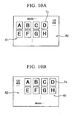
- the display control unit 51 receives an input, and switches the display of the display 41 from a standard mode shown in FIG. 9A to the inverted mode shown in FIG. 9B .
- an image acquired by the imaging mechanism 56 is displayed on the first region R1, and textual information, such as a manipulation menu and various parameters, is displayed on the second region R2.
- textual information such as a manipulation menu and various parameters
- FIG. 9B the user views a display on which upper and lower sides are inverted.
- the textual information displayed on the second region R2 is vertically flipped from the state in the standard mode, and is displayed.
- the upper and lower sides of an image displayed on the first region R1 are not reversed even in the inverted mode. This is provided to keep a correspondence relationship between an image and the manipulation of the first joystick 21.
- a thumbnail screen showing the list of images stored in the storage unit 53 it is not necessary to take the above-described matter into consideration. Therefore, in the inverted mode shown in FIG 10B , the images are vertically reversed, and are aligned and displayed within the first region R1. As a result, the orientation of a thumbnail image Tn that the user views is the same as that of the standard mode shown in FIG 10A . Additionally, as for a retrieve screen (not shown) that displays one image corresponding to an arbitrary thumbnail image Tn selected from the thumbnail screen, an image is vertically reversed and displayed in the inverted mode.
- the first joystick 21 in a neutral state and the insertion part 10 connected to the housing part 60 are arranged so as to be coaxial with each other. Therefore, in the mechanical curving mechanism 23 using the manipulating member 14, the amount of advance or retreat of each manipulating member 14 during curving manipulation becomes uniform, and the curving portion 13 can be suitably curved.
- the first slope 71 is formed above and below the insertion part 10 and the second slope 72 is formed above and below the insertion part 10 at the back face 65B to which the insertion part 10 is connected.
- the back face 65B is formed in a convex shape that rises up toward the insertion part 10 in a side view of the housing 61. Accordingly, the hand of the user holding the lower portion 65 is brought into a state where the palm of the hand is made concave so as to wrap around the back face 65B.
- at least one finger among the four fingers other than the thumb is arranged on the first slope 71 and the second slope 72 so as to pinch the insertion part 10 in the vertical direction.
- a force such as a moment that acts on the housing part 60 through the long insertion part 10
- a force can be suitably received by a user's hand regardless of the direction in which the moment acts, and the housing 61 can be stably held.
- the user can suitably hold the housing part 60 with the hand holding the lower portion 65, and can suitably stabilize the positions of the upper front face 64A and lower front face 65A. That is, it is not easily brought about a state which difficult to recognize the display part 40 or to manipulate the manipulating part 20 such as the manipulating part 20 of the upper front face 64A is pushed toward the back face or the lower front face 65A becomes parallel to the perpendicular direction is not easily brought about. As a result, manipulation can be performed with the housing part 60 being held in a state where the display 41 is easily seen and the manipulating part 20 is easily manipulated.
- a swinging center 21 A of the first joystick 21 is located in a region A2 specified by the first slope 71 and the second slope 72 where user's fingers are arranged when the housing 61 is held and by the distal end 21B of the first joystick 21 that protrudes to the front face 65A, in a side view of the housing 61 shown in FIG 6 , by virtue of the shape of the lower back face 65B described above. Accordingly, a situation where the housing part 60 is collapsed due to the force that acts on the housing part 60 when the first joystick 21 is manipulated can be suitably suppressed, and an endoscope apparatus that does not easily cause fatigue even if being manipulated for a long period of time can be provided.
- the second slope 72 has the first holding face 72A and the second holding face 72B. Accordingly, the tips of fingers (for example, the third finger F3 and the little finger F4) arranged on the second slope 72 are arranged along either the first holding face 72A or the second holding face 72B when the lower portion 65 is held.
- the fingers F3 and F4, and the like that are arranged on the second slope 72, and the thumb Th have the positional relationship of substantially facing each other.
- the force that acts with inclination manipulation by the third finger F3, the little finger F4, and the like to incline the housing 61 can be suitably received, and to perform manipulation while maintaining a state where the housing 61 is stabilized.
- the second slope 72 is formed so as to be longer than the first slope 71 in the dimension of the housing 61 in the vertical direction, fingers to be arranged on the second slope 72 can be arranged so as to be moderately separated from each other, and more stable holding of the housing at the time of use becomes possible.
- FIG 11 An example in a case where holding and manipulation are performed with the left hand is shown in FIG 11 .
- the tip of a finger arranged on the second slope 72 is arranged at the second holding face 72B.
- the tip of a finger is arranged at the first holding face 72A, but, since the first holding face 72A and the second holding face 72B are symmetrically arranged across the center of the housing 61 in the right-and-left direction, the same effect is exhibited.
- the friction members 73 having elasticity are attached to the first holding face 72A and the second holding face 72B.
- the second joystick 22 protrudes from the bottom of the concave portion 70 provided in the front face 65A of a lower, and the height thereof is set so that the distal end of the second joystick does not protrude from the front face 65A. For this reason, the second joystick 22 is not hindering the manipulation of the first joystick 21, even the second joystick is arranged in a place where the joystick is easily manipulated by the thumb Th around the first joystick 21 and then, operability can be further improved.
- the housing can be suitably self-supported such that the upper portion 64 is turned down and the lower portion 65 is turned up, and can be used in the inverted mode by bringing the housing 61 contact with the ground at the two ground contact members 68 provided at the upper portion 65, and the connecting portion between the insertion part 10 and the housing part.
- the housing can be suitably used even in the manipulation for a prolonged time.
- display of the display 41 is easily seen even when being used in the inverted mode, and can be suitably used.
- the grip face 82 is formed in the shape of a spindle that is convex toward the back face. In this grip face 82, portions equivalent to the first face and the second face become curved surfaces. However, since the grip face runs along the curve of a finger of a holding user, the finger can be suitably arranged, and stable holding can be performed.
- a hand Hd is shown by a two-dot chain line in FIG. 12 in a state where the first joystick 21 is placed at the tip side and the display part 40 is placed at the grip side, it is also possible to turn the display part 40 up and hold the display part similarly to the above-described endoscope apparatus 1.
- FIG 13 shows an endoscope apparatus 91 not part of the invention in which a grip face 92 is formed in the shape of a spherical surface. Since such a grip face 92 also fits the curve of a finger F of a holding user as schematically shown in FIG 14A , the finger F can be suitably arranged.
- FIG 14B to FIG 14E schematically show examples of the shape of the grip face, respectively, in bottom views (the same state as FIG 5 ) of the housing.
- a grip face 94 shown in FIG 14B or a grip face 95 shown in FIG 14C have a first holding face 94A or 95A and a second holding face 94B or 95B that rise up, respectively, from the edges of a housing in the right-and-left direction, respectively, and becomes convex toward the back face in the bottom view of the housing.
- a connecting portion between the first holding face and the second holding face becomes a top portion 94C or 95C.
- a user can hook a portion of the finger F (for example, a first joint) of the finger F on the top portion 94C or 95C, and can further stably hold.
- the first holding face 95A and the second holding face 95B are curved with a predetermined curvature so as to become concave toward the back face.
- the grip face has a top portion 95C, the fundamental shape of the grip face 95 is convex toward the back face.
- a grip face 96 having a convex portion 96B that protrudes above a spherical fundamental plane face 96A is shown in FIG. 14D .
- a user also can hook a first joint of the finger F on the convex portion 96B, and can stably hold.
- a grip face 97 having a concave portion 97B on a spherical fundamental face 97A is shown in FIG. 14E .
- a user can hook a first joint of the finger F on the concave portion 97B to stabilize holding.
- the concave portion 97B itself is not convex toward the back face in the grip face 97, since the grip face has the spherical fundamental face 97A, the fundamental shape is convex toward the back face.
- the grip face can be suitably set according to the application of an endoscope apparatus, a target user, or the like while having a fundamental shape that is convex toward the back face.
- the ground contact members 68 for self-supporting the housing 61 in the inverted mode are arranged at two locations apart from each other.
- the ground contact members may be arranged on one straight line by a predetermined length (for example, to such a degree that two locations where the ground contact members 68 of the present embodiment are arranged are connected together) at an upper peripheral edge portion of the upper back face 64B. Even in this way, the housing 61 can be suitably self-supported and can be used in the inverted mode.
- the illumination mechanism 12 is arranged at the distal end of the insertion part 10 .
- the light source may be arranged within the housing, and the light guide member, such as a light guide, may be arranged within the insertion part to supply illumination light to the distal end of the insertion part.
- an endoscope apparatus in which only a battery can be used as a power source.
- a configuration in which electric power can be supplied from an external power source in addition to the battery may be adopted.
- an endoscope apparatus may be provided with a dummy member, which has the same shape and size as a battery, is lighter in weight than the battery, and which is capable of setting the position of the center of gravity within a predetermined region in a state where the dummy member is mounted on a battery accommodating portion and an endoscope apparatus may be used when an external power source is used.
- the example in which the reinforce member and the self-supporting auxiliary member are attached to the proximal end portion of the insertion part connected to the housing has been described.
- only one of the reinforcing member and the self-supporting auxiliary member may be attached to the proximal end portion.
- an endoscope apparatus capable of being self-supported only by the connecting portion of the insertion part, and the edge of the housing at the display part side without being attached to any of the reinforcing member and the self-supporting auxiliary member may be configured.
- the invention can be widely applied to observation of a specimen at the point of an elongated insertion path, internal observation of a specimen, or the like.
Landscapes
- Health & Medical Sciences (AREA)
- Life Sciences & Earth Sciences (AREA)
- Surgery (AREA)
- Biomedical Technology (AREA)
- Medical Informatics (AREA)
- Optics & Photonics (AREA)
- Pathology (AREA)
- Radiology & Medical Imaging (AREA)
- Biophysics (AREA)
- Engineering & Computer Science (AREA)
- Physics & Mathematics (AREA)
- Heart & Thoracic Surgery (AREA)
- Nuclear Medicine, Radiotherapy & Molecular Imaging (AREA)
- Molecular Biology (AREA)
- Animal Behavior & Ethology (AREA)
- General Health & Medical Sciences (AREA)
- Public Health (AREA)
- Veterinary Medicine (AREA)
- Endoscopes (AREA)
- Instruments For Viewing The Inside Of Hollow Bodies (AREA)
Description
- The present invention relates to an endoscope apparatus, and more particularly, to an endoscope apparatus in which a manipulating part that curves an insertion part and a display part that displays an image acquired by the insertion part are accommodated in the same housing.
- An endoscope apparatus including an imaging mechanism at a distal end portion of a long insertion part is widely used for observation of a specimen beyond an elongated insertion path, internal observation of a specimen, or the like.
- In recent years, as one direction for improvement of endoscope apparatuses, it is being studied in which a display part that displays an image acquired by an insertion part and a manipulating part that performs curving manipulation of the insertion part are accommodated in one housing, and in which carrying and manipulation of an endoscope apparatus are made easy.
-
Patent Document 1 discloses an endoscope apparatus in which a display part and a manipulating part are accommodated in a common housing. In this endoscope apparatus, a monitor part is arranged at one end of the housing, and a substantially rod-shaped grip is formed at the other end. A manipulating part having a joystick is arranged between the grip and a monitor part. When a user manipulates the joystick, the user manipulates the joystick with a thumb with the rod-shaped grip being gripped. - [Patent Document 1] Japanese Unexamined Patent Application, First Publication No.
2004-109222 - However, in the endoscope apparatus disclosed in
Patent Document 1, the joystick is manipulated by the thumb at a position closer to the monitor part than fingers other than the thumb holding the grip. Therefore, for example, when the joystick is pushed toward the monitor part or the like, the housing is not stable due to the power that acts on the housing, and it becomes difficult to manipulate the joystick. - At this time, although it is also considered that a force is applied to fingers other than the thumb in order to stabilize the housing, since the housing is generally formed from resin or the like, for example, the fingers slip on the surface of the rod-shaped grip. Due to this, it is not so easy to stabilize the housing.
- The invention has been made in consideration of the above circumstances, and the object thereof is to provide an endoscope apparatus in which more stable holding and manipulation of the housing is possible.
- An endoscope apparatus of the present invention includes an endoscope apparatus according to
claim 1. - Friction members may be arranged at the first holding face and the second holding face, and the frictional coefficient of the first holding face and the second holding face may be made higher than that of other portions of the housing.
- Additionally, the friction members may be elastically deformable.
- The first face and the second face may be grip faces on which fingers are arranged when a user uses the housing, and the second face may be longer than the first face in the dimension of the housing in a vertical direction.
- Additionally, the first holding face and the second holding face may be symmetrically arranged across the center of the housing in the right-and-left direction.
- According to the endoscope apparatus of the invention, holding and manipulation of the housing can be more stably performed.
-
-
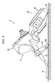
FIG 1 is an overall perspective view showing an endoscope apparatus of one embodiment of the invention. -
FIG 2 is a diagram showing a first joystick and a manipulating mechanism of the endoscope apparatus. -
FIG. 3 is a back view of a housing of the endoscope apparatus. -
FIG 4 is a cross-sectional view in an upper portion of the housing in a front-and-rear direction. -
FIG 5 is a bottom plan view of the housing. -
FIG. 6 is a cross-sectional view of a manipulating part, a display part, and a housing part of the endoscope apparatus along the center axis of an insertion part. -
FIG. 7 is a functional block diagram of the endoscope apparatus. -
FIG. 8 is a view showing a ground contact aspect in an inverted mode of the endoscope apparatus. -
FIG 9A is a view showing an example of screen display in a standard mode of the endoscope apparatus. -
FIG 9B is a view showing an example of screen display in the inverted mode of the endoscope apparatus. -
FIG 10A is a view showing an example of screen display in the standard mode. -
FIG 10B is a view showing an example of screen display in the inverted mode. -
FIG 11 is a view showing an example of a user's hand holding the housing of the endoscope apparatus. -
FIG 12 is an overall perspective view showing an endoscope apparatus not part of the invention. -
FIG 13 is an overall perspective view showing an endoscope apparatus not part of the invention. -
FIG 14A is a schematic view showing the shape of a grip face in the apparatus ofFig. 13 . -
FIG. 14B is a schematic view showing the shape of a grip face in the endoscope apparatus ofFig. 13 . -
FIG. 14C is a schematic view showing the shape of a grip face in the endoscope apparatus ofFig. 13 . -
FIG. 14D is a schematic view showing the shape of a grip face in the endoscope apparatus ofFig. 13 . -
FIG. 14E is a schematic view showing the shape of a grip face in the endoscope apparatus ofFig. 13 . - An endoscope apparatus of one embodiment of the invention will be described with reference to
FIGS. 1 to 11 . Anendoscope apparatus 1 of the present embodiment is used for observation of a specimen beyond an elongated insertion path, internal observation of a specimen, or the like. As shown inFIG 1 , theendoscope apparatus 1 includes along insertion part 10, a manipulatingpart 20 for performing curving manipulation of theinsertion part 10, adisplay part 40 that displays an image acquired by theinsertion part 10, and ahousing part 60 including ahousing 61 that accommodates the manipulatingpart 20 and thedisplay part 40. - The
insertion part 10 has a well-known configuration in which a distal end portion thereof includes anillumination mechanism 12, such as an observationoptical system 11 and an LED, and an imaging mechanism, such as a CCD (not shown). Theinsertion part 10 can acquire an image, such as a still image, a moving image, or the like of a specimen in front of the distal end portion. Additionally, theinsertion part 10 has a well-known curvingportion 13 in which a plurality of joint rings or curvable pieces (hereinafter generically referred to as "joint rings or the like") that is not shown is arranged and coupled together in the direction of an axis. Theinsertion part 10 can be curved in four directions apart from the center axis in two axes that intersect its own center axis. Manipulating members, such as four wires that corresponds to the four directions, are connected to a joint ring or the like at the most distal end among the plurality of joint rings or the like. Each manipulating member extends to the inside of thehousing part 60 through each joint ring or the like, and is connected to the manipulatingpart 20. - The manipulating
part 20 has a first joystick (manipulating rod) 21 for manipulating the curvingportion 13, asecond joystick 22 for manipulating a cursor or the like displayed on thedisplay part 40, and a curving mechanism manipulated via thefirst joystick 21. -
FIG 2 is a diagram showing thefirst joystick 21 and thecurving mechanism 23. - The
curving mechanism 23 includes aframe body 24, and a swingingbody 25 attached to theframe body 24. Theframe body 24 is formed of a material having a certain rigidity, such as metal, and includes a swingingbody accommodation portion 26 to which the swinging body is attached, and aguide portion 27 provided to extend from the swingingbody accommodation portion 26. - The swinging
body 25 includes afirst member 28 rotatably attached to theframe body 24, asecond member 29 rotatably attached to thefirst member 28, and a manipulatingmember fixing portion 30 attached to thesecond member 29. - The
first member 28 is formed of metal, resin, or the like, and has arotating shaft portion 28A. The swinging body accommodation portion includes thefirst end 26A to which theguide portion 27 extends, and thesecond end 26B which is opposite to thefirst end 26A. Thefirst member 28 is attached to thesecond end 26B of the swingingbody accommodation portions 26 opposite to thefirst end 26A to which theguide portion 27 extends so as to be able to rotate on the axis of therotating shaft portion 28A by a predetermined range. - The
second member 29 is formed of metal, resin, or the like, and has a substantially columnar shaft portion 29A and arotating shaft portion 29B that is formed substantially in the shape of a column and is formed at one end of the shaft portion 29A. The center axis of the shaft portion 29A and the center axis of therotating shaft portion 29B are orthogonal to each other. - The
second member 29 is attached to thefirst member 28 so that both of the axis of the shaft portion 29A and the axis of therotating shaft portion 29B are orthogonal to the center axis of therotating shaft portion 28A of thefirst member 28. Thesecond member 29 can be rotated about the axis of therotating shaft portion 29B with respect to thefirst member 28 in a predetermined range by acutout portion 28B which is formed in thefirst member 28 so as not to interfere with the shaft portion 29A. - The manipulating
member fixing portion 30 includes afirst arm portion 31 that protrudes toward both sides in a first direction, and a second arm portion (not shown) that protrudes toward both sides in a second direction which is orthogonal to the first arm portion. Ends of the four manipulatingmembers 14 extending from theinsertion part 10 are fixed to both longitudinal ends of thefirst arm portion 31 and the second arm portion. A connectingmember 15 is attached to the end of each manipulatingmember 14. Both the longitudinal ends of thefirst arm portion 31 and the second arm portion are provided with receivingmembers 32 to which the connectingmembers 15 are attached. Each manipulatingmember 14 is connected and fixed to the manipulatingmember fixing portion 30 by fitting each connectingmember 15 into each receivingmember 32. - As shown in
FIG 2 , the swingingbody 25 is attached to thesecond end 26B of the swingingbody accommodation portion 26 so that the center axis of the shaft portion 29A of thesecond member 29 becomes substantially coaxial with the center axis of theguide portion 27 of theframe body 24. The four manipulatingmembers 14 extending from theinsertion part 10 are connected to the manipulatingmember fixing portion 30 through theguide portion 27. The shape of theframe body 24 is set so as not to interfere with the swinging of the swingingbody 25, and the push or pull (advance or retreat) of the manipulatingmember 14 accompanying this. - The
first joystick 21 is attached to thesecond member 29 so as to become substantially coaxial with the shaft portion 29A of thesecond member 29. Accordingly, thefirst joystick 21 is inclined in arbitrary directions, so that the swingingbody 25 can be swung with respect to theframe body 24 and the manipulatingmember 14 connected to the manipulatingmember fixing portion 30 can be advanced or retreated in the longitudinal direction of theinsertion part 10. As a result, the curvingportion 13 can be curved in a direction opposite to the direction in which thefirst joystick 21 is inclined. - The
second joystick 22 is an electrical manipulating mechanism of which one end is attached to a substrate. The inclined direction of thesecond joystick 22 is inputted to the substrate thereby, a cursor is moved in the direction concerned by inputting the pushed-down direction to a board. - As shown in
FIG. 1 , thedisplay part 40 has a well-known configuration including adisplay 41, such as an LCD, and a control substrate (to be described below) that controls display of thedisplay 41. An aspect in which thedisplay part 40 is accommodated in thehousing 61 will be described in detail in the description of thehousing part 60. - The
housing part 60 includes ahousing 61 in which the manipulatingpart 20 and thedisplay part 40 are accommodated, a reinforcingmember 62 attached to a connecting portion between thehousing 61 and theinsertion part 10, and a holder (self-supporting auxiliary member) 63 attached to the proximal end of theinsertion part 10. - The
housing 61 is formed of resin or the like, and includes anupper portion 64 provided with thedisplay part 40, and alower portion 65 connected to theupper portion 64 and having the manipulatingpart 20 arranged therein. -
FIG. 3 is a back view of thehousing 61 that is shown with theholder 63 shown inFIG 1 is omitted. As shown inFIGS. 1 and3 , theupper portion 64 is formed in a substantially rectangular parallelepiped shape corresponding to thedisplay 41 of thedisplay part 40, and thedisplay 41 is arranged at afront face 64A. Within theback face 64B of theupper portion 64,fins 66 for heat dissipation are provided on the upper side of aback face 64B of theupper portion 64, and alid 67 of a battery accommodation portion (to be described below) is provided on the lower side of theback face 64B.
Furthermore,ground contact members 68 made from rubber, elastomer, or the like are attached to two locations of a top side edge of theback face 64B so as to enhance the frictional coefficient. Moreover,fittings 69 for attaching accessories, such as a strap, are attached to the lower side to which thelower portion 65 is connected. -
FIG 4 is a cross-sectional view of theupper portion 64 in the front-and-rear direction. Within theupper portion 64, thedisplay part 40 is accommodated at thefront face 64A, and the battery B is arranged at theback face 64B. Acontrol board 42 having anIC 43 is connected to thedisplay 41. The control board is accommodated on the back side of thedisplay 41 in a state that theIC 43 is faced to theback face 64B. - The
IC 43 that emits heat during operation is accommodated at a position near thefins 66 provided at an upper portion of theback face 64B. A heat-conduction sheet 44 is interposed between theIC 43 and thefins 66. - The battery B is accommodated in the
battery accommodation portion 74 formed closer to the back face than thecontrol board 42. Aheat insulation sheet 75 is arranged at a wall surface on the front side of thebattery accommodation portion 74 so that the heat emitted from the battery B is not easily transferred to thedisplay part 40. - Through the above configuration, the
IC 43 and the battery B that generate heat when theendoscope apparatus 1 is used are arranged apart from each other. Generation of heat from theIC 43 is efficiently diffused to the outside of the apparatus from thefins 66 through the heat-conduction sheet 44, and generation of heat of the battery B is not easily transferred to thedisplay part 40 as described above. As a result, a structure in which display of thedisplay 41 or the like is not affected while accommodating two heating elements of theIC 43 and the battery B in theupper portion 64 is realized. - The
lower portion 65 is a portion that a user holds with a hand when theendoscope apparatus 1 is used and manipulated. As shown inFIG. 1 , thelower portion 65 is connected to theupper portion 64 with an upper front face 64A, and afront face 65A from a predetermined angle so that thedisplay 41 is easily seen when a user holds the lower portion. - The peripheral edge of the
front face 65A is formed by a curve, and has such a shape that is constricted and is narrowed at an intermediate portion in a vertical direction and becomes gradually wider toward the lower portion. Furthermore, the peripheral edge of the front face has a symmetrical shape so that the peripheral edge can be suitably held by either the right or left hands. - The
second joystick 22 of the two joysticks of the manipulatingpart 20 is arranged on the lower side of thefront face 65A, and thefirst joystick 21 thereof is arranged above thesecond joystick 22. A straight line that connects thefirst joystick 21 and thesecond joystick 22 together are on line where a central portion of thedisplay part 40 in the right-and-left direction (direction orthogonal to the vertical direction of the housing 61), in the plan view of thehousing 61. The distal end of thefirst joystick 21 protrudes above thefront face 65A in a predetermined length so as to be easily manipulated by a user holding thelower portion 65. Thesecond joystick 22 protrudes from the bottom of theconcave portion 70 provided in thefront face 65A. Thesecond joystick 22 is set to have a height that the distal end thereof does not protrude from thefront face 65A. - As shown in
FIG. 3 , theinsertion part 10 is connected to aback face 65B of thelower portion 65. Theinsertion part 10 extends from an intermediate portion of theback face 65B in the vertical direction. A first slope (first face) 71 that rises up toward theinsertion part 10 is formed on the side of theback face 65B above theinsertion part 10. A second slope (second face) 72 that rises up toward theinsertion part 10 is formed below theinsertion part 10. Theback face 65B of thelower portion 65 is formed in a shape, which becomes convex rearward in a side view of thehousing 61, by thefirst slope 71 and thesecond slope 72. Through such a configuration, theback face 65B of the back face of thehousing 61 is used as a portion (grip face) on which a user's fingers are arranged when a user holds thehousing 61. - The
first slope 71 is set to have such a dimension such that the index finger and middle finger of a hand with a standard size can be aligned in the vertical direction and can be hooked simultaneously. Thefirst slope 72 functions as a first finger hook portion. Thefirst slope 71 is provided with a freezing/recording button 71 A for recording an image acquired by an imaging means of theinsertion part 10 as a still image or a moving image, and the button can be manipulated by an index finger when a user holds thelower portion 65. - The
second slope 72 is set to have such a dimension such that the third finger and little finger of a hand with a standard size can be aligned in the vertical direction and can be hooked simultaneously. Thesecond slope 72 functions as a second finger hook portion. As shown by a two-dot chain line shown inFIG. 5 , thelower portion 65 is formed so that the cross-sectional area that is parallel to the right-and-left direction of thehousing 61 and orthogonal to the vertical direction becomes gradually smaller toward the lower end by providing thesecond slope 72. Thesecond slope 72 has afirst holding face 72A and asecond holding face 72B that incline toward the peripheral edges of theback face 65B in the right-and-left direction, respectively. Additionally, thesecond slope 72 has athird holding face 72C that extends toward a lower peripheral edge of theback face 65B, and connects the first holdingface 72A to thesecond holding face 72B together. Thereby, thesecond slope 72 is formed in a shape which becomes convex toward theback face 65B in a bottom view of thehousing 61. Afriction member 73 made of an elastically deformable material, such as rubber or elastomer, is attached to each face of thesecond slope 72. This makes the frictional coefficient of each holding face higher than other portions of thehousing 61. - Additionally, as shown in
Fig. 6 , the dimension of thehousing 61 in the vertical direction is set such that thesecond slope 72 is longer than thefirst slope 71. - The reinforcing
member 62 is formed in a substantially cylindrical shape of which the external diameter of one end is reduced in the shape of a taper. The reinforcingmember 62 is arranged so as to cover the proximal end of theinsertion part 10 connected to thehousing 61 and its surroundings. The reinforcingmember 62 has certain rigidity and the portion of theinsertion part 10 which is covered with the reinforcingmember 62 maintains a linear state. That is, the reinforcingmember 62 functions as a bending stopper that prevents the coveredinsertion part 10 from bending at a steep acute angle. -
FIG 6 is a cross-sectional view of the manipulatingpart 20, thedisplay part 40, and thehousing part 60 along the center axis of theinsertion part 10. Theholder 63 is formed of resin or the like, and as shown inFIG. 6 , has a first throughhole 63A with a larger diameter at a first end and has a second throughhole 63B with a smaller diameter at a second end. Theholder 63 is mounted on the connecting portion between theinsertion part 10 and thehousing 61 so that the reinforcingmember 62 is inserted into the first throughhole 63A. The internal diameter of the second throughhole 63B is slightly larger than the external diameter of theinsertion part 10 so that the through hole allows theinsertion part 10 to be inserted thereinto and held thereby. The second end of theholder 63 is provided with aground contact face 63C, and the details thereof will be described below. - As shown in
FIG 6 , the curvingmechanism 23 is accommodated in thelower portion 65 of thehousing 61 so that theguide portion 27 is located at theback face 65B, and the center axis of theinsertion part 10 and thefirst joystick 21 in a non-manipulated neutral state are made coaxial or substantially coaxial with each other. - Since the battery B is accommodated in the
upper portion 64 of thehousing 61, the center of gravity of theendoscope apparatus 1 excluding theinsertion part 10 is set to a designed center-of-gravity position CG1 shown inFIG 6 when the battery B is mounted and used. The actual center-of-gravity position moves slightly due to the allowable range for manufacturing errors or the like in an individual product. However, the actual center-of-gravity position is present within a region within a predetermined radius having the designed center-of-gravity position CG1 as a center and that is a region A1 substantially including the connecting portion between theupper portion 64 and thelower portion 65. -
Fig. 7 is a functional block diagram of theendoscope apparatus 1. In addition to the above describeddisplay control unit 51, theendoscope apparatus 1 includes animage processing unit 52 that processes an image signal acquired by theimaging mechanism 56 of theinsertion part 10, astorage unit 53 that stores the acquired still image, moving image, or the like, and acontrol unit 54 that controls the overall operation of theendoscope apparatus 1 including light quantity adjustment or the like of theillumination mechanism 12. - The
image processing unit 52 and thecontrol unit 54 are stored in, for example, an IC (not shown) that is attached to thecontrol board 42. Various well-known storage media can be used as thestorage unit 53. Additionally, thestorage unit 53 may be detachably attached to thehousing part 60. Theimaging mechanism 56 and theillumination mechanism 12 are connected to theimage processing unit 52 or thecontrol unit 54 by awiring line 55 that extends to the inside of thehousing part 60 through theinsertion part 10. Thesecond joystick 22 of the manipulatingpart 20 is electrically connected to thecontrol unit 54 via the substrate (not shown). - The operation when the
endoscope apparatus 1 configured as described above is used will be described. - With the battery B accommodated in and mounted on the
battery accommodation portion 74, a user starts theendoscope apparatus 1, inserts the distal end of theinsertion part 10 into the inside of a specimen, into an access path to the specimen, or the like, and advances the distal end to a part to be observed. - When the user wants to change the orientation of the distal end of the
insertion part 10, theinsertion part 10 can be curved in a desired orientation by manipulating thefirst joystick 21 of the manipulatingpart 20 to advance or retreat the manipulatingmember 14 connected to the curvingmechanism 23. - At this time, the user holds the
lower portion 65 of thehousing 61 so as to wrap around the lower portion with a dominant hand, and places and manipulates a thumb at the end of thefirst joystick 21 protruding from thefront face 65A. An example of the positional relationship between user's fingers and thehousing part 60 during the manipulation is shown inFIG. 6 . During the manipulation, in a side view of thehousing 61, at least the index finger F1 is located on thefirst slope 71 of thelower back face 65B, and the little finger F4 is located on thesecond slope 72. Accordingly, the connecting portion between theinsertion part 10 and thehousing part 60 is located between the index finger F1 and the little finger F4, and theinsertion part 10 extends from theback face 65B that is a grip face. - In addition, in the example of
FIG 6 , the middle finger F2 is arranged on thefirst slope 71 in addition to the index finger F1, and the third finger F3 is arranged on thesecond slope 72 in addition to the little finger F4. - When the distal end of the
insertion part 10 reaches a part to be observed, the user performs observation or inspection of the specimen while manipulating the manipulatingpart 20. If needed, the freezing/recording button 71A is manipulated to record a still image, a moving image, or the like of a target part. Various acquired images are stored in thestorage unit 53. - When a hand holding the
housing 61 gets tired because the operating time becomes long, thehousing 61 can be placed on the ground or on a desk and manipulated. When thehousing 61 is placed, as shown inFIG 8 , the twoground contact members 68 provided at theupper portion 64, and the connecting portion between theinsertion part 10 and thehousing 61, more specifically, the connecting portion is a boundary portion between the reinforcingmember 62 and theinsertion part 10 including and a predetermined range in front of or behind the boundary portion are brought into contact with the ground. Thereby, thehousing 61 is suitably self-supported such that theupper portion 64 is turned down and thelower portion 65 is turned up. - Since the proximal end portion of the
insertion part 10 extending from thehousing 61 is held in the shape of a straight line by the reinforcingmember 62, even if there is noholder 63, the proximal end portion is suitably self-supported without theholder 63. However, as shown inFIG. 8 , if the second end of theholder 63 is turned toward theupper portion 64 of thehousing 61, theground contact face 63C is located on the ground contact face of thehousing 61 specified by the connecting portion that contacts the ground and theground contact member 68. As a result, theholder 63 can assist thehousing 61 in being suitably self-supporting, and can place thehousing 61 in a more stable state. Hereinafter, the state in which theendoscope apparatus 1 is used with thehousing 61 placed in this way is referred to as an "inverted mode". - When the apparatus is used with the
housing 61 placed as described above, the user performs a predetermined manipulation input via the manipulatingpart 20 to switch a display mode of a screen. Thedisplay control unit 51 receives an input, and switches the display of thedisplay 41 from a standard mode shown inFIG. 9A to the inverted mode shown inFIG. 9B . - As shown in
FIG. 9A , in the standard mode, an image acquired by theimaging mechanism 56 is displayed on the first region R1, and textual information, such as a manipulation menu and various parameters, is displayed on the second region R2. In the inverted mode shown inFIG. 9B , the user views a display on which upper and lower sides are inverted. For this reason, the textual information displayed on the second region R2 is vertically flipped from the state in the standard mode, and is displayed. On the other hand, the upper and lower sides of an image displayed on the first region R1 are not reversed even in the inverted mode. This is provided to keep a correspondence relationship between an image and the manipulation of thefirst joystick 21. Additionally, when recording is performed by manipulating the freezing/recording button 71A, there is a purpose of storing images in thestorage unit 53 with a vertically-structured relationship being unified even if the images are recorded in any of the standard mode and the inverted mode. - On the other hand, as for a thumbnail screen showing the list of images stored in the
storage unit 53, it is not necessary to take the above-described matter into consideration. Therefore, in the inverted mode shown inFIG 10B , the images are vertically reversed, and are aligned and displayed within the first region R1. As a result, the orientation of a thumbnail image Tn that the user views is the same as that of the standard mode shown inFIG 10A . Additionally, as for a retrieve screen (not shown) that displays one image corresponding to an arbitrary thumbnail image Tn selected from the thumbnail screen, an image is vertically reversed and displayed in the inverted mode. - As described above, according to the
endoscope apparatus 1 of the present embodiment, thefirst joystick 21 in a neutral state and theinsertion part 10 connected to thehousing part 60 are arranged so as to be coaxial with each other. Therefore, in themechanical curving mechanism 23 using the manipulatingmember 14, the amount of advance or retreat of each manipulatingmember 14 during curving manipulation becomes uniform, and the curvingportion 13 can be suitably curved. - In the
lower portion 65 of thehousing 61 in which the curvingmechanism 23 is accommodated, thefirst slope 71 is formed above and below theinsertion part 10 and thesecond slope 72 is formed above and below theinsertion part 10 at theback face 65B to which theinsertion part 10 is connected. Thereby, theback face 65B is formed in a convex shape that rises up toward theinsertion part 10 in a side view of thehousing 61. Accordingly, the hand of the user holding thelower portion 65 is brought into a state where the palm of the hand is made concave so as to wrap around theback face 65B. In addition, at least one finger among the four fingers other than the thumb is arranged on thefirst slope 71 and thesecond slope 72 so as to pinch theinsertion part 10 in the vertical direction. - As a result, a force, such as a moment that acts on the
housing part 60 through thelong insertion part 10, can be suitably received by a user's hand regardless of the direction in which the moment acts, and thehousing 61 can be stably held. - Moreover, since the position of the center of gravity of the
endoscope apparatus 1 excluding theinsertion part 10 is set in the above-described region A1. Therefore, the user can suitably hold thehousing part 60 with the hand holding thelower portion 65, and can suitably stabilize the positions of the upperfront face 64A and lowerfront face 65A. That is, it is not easily brought about a state which difficult to recognize thedisplay part 40 or to manipulate the manipulatingpart 20 such as the manipulatingpart 20 of the upper front face 64A is pushed toward the back face or the lowerfront face 65A becomes parallel to the perpendicular direction is not easily brought about. As a result, manipulation can be performed with thehousing part 60 being held in a state where thedisplay 41 is easily seen and the manipulatingpart 20 is easily manipulated. - Moreover, due to the shape of the
lower back face 65B described above, a swingingcenter 21 A of thefirst joystick 21 is located in a region A2 specified by thefirst slope 71 and thesecond slope 72 where user's fingers are arranged when thehousing 61 is held and by the distal end 21B of thefirst joystick 21 that protrudes to thefront face 65A, in a side view of thehousing 61 shown inFIG 6 , by virtue of the shape of thelower back face 65B described above. Accordingly, a situation where thehousing part 60 is collapsed due to the force that acts on thehousing part 60 when thefirst joystick 21 is manipulated can be suitably suppressed, and an endoscope apparatus that does not easily cause fatigue even if being manipulated for a long period of time can be provided. - Moreover, the
second slope 72 has the first holdingface 72A and thesecond holding face 72B. Accordingly, the tips of fingers (for example, the third finger F3 and the little finger F4) arranged on thesecond slope 72 are arranged along either the first holdingface 72A or thesecond holding face 72B when thelower portion 65 is held. - For this reason, as shown in
FIG 11 , the fingers F3 and F4, and the like that are arranged on thesecond slope 72, and the thumb Th have the positional relationship of substantially facing each other. As a result, when thefirst joystick 21 is inclined with the thumb Th in the direction (for example, the direction of an arrow D1 shown inFIG 11 ) separating from the grip side of the hand, such as the direction in which the thumb Th extends, the force that acts with inclination manipulation by the third finger F3, the little finger F4, and the like to incline thehousing 61 can be suitably received, and to perform manipulation while maintaining a state where thehousing 61 is stabilized. Here, since thesecond slope 72 is formed so as to be longer than thefirst slope 71 in the dimension of thehousing 61 in the vertical direction, fingers to be arranged on thesecond slope 72 can be arranged so as to be moderately separated from each other, and more stable holding of the housing at the time of use becomes possible. - This effect is similarly exhibited even in an electrical motor-driven type in which the curving mechanism uses a motor or the like. However, since the force that is generated with the manipulation of the
first joystick 21 becomes large in a case where a mechanical curving mechanism only using a manipulating member is provided, the effect is greater in the endoscope apparatus like the present embodiment. - This effect is similarly obtained even when a button or the like is arranged on the front to which the thumb Th extends in the manipulating
part 20 and the button is manipulated in the manipulatingpart 20. An example in a case where holding and manipulation are performed with the left hand is shown inFIG 11 . In this case, the tip of a finger arranged on thesecond slope 72 is arranged at thesecond holding face 72B. When a user performs holding and manipulation with the right hand, the tip of a finger is arranged at the first holdingface 72A, but, since the first holdingface 72A and thesecond holding face 72B are symmetrically arranged across the center of thehousing 61 in the right-and-left direction, the same effect is exhibited. - Moreover, since the
friction members 73 having elasticity are attached to the first holdingface 72A and thesecond holding face 72B. Through this configuration, even when a relatively larger force acts on the finger arranged on thesecond slope 72, the positional relationship between thesecond slope 72 and the finger is suitably held. As a result, thehousing part 60 can be held even during manipulation, and stable manipulation can be performed. - The
second joystick 22 protrudes from the bottom of theconcave portion 70 provided in thefront face 65A of a lower, and the height thereof is set so that the distal end of the second joystick does not protrude from thefront face 65A. For this reason, thesecond joystick 22 is not hindering the manipulation of thefirst joystick 21, even the second joystick is arranged in a place where the joystick is easily manipulated by the thumb Th around thefirst joystick 21 and then, operability can be further improved. - In addition, by bringing the
housing 61, the twoground contact members 68 provided at theupper portion 65 and the connecting portion between theinsertion part 10 and the housing part into contact with the ground, the housing can be suitably self-supported such that theupper portion 64 is turned down and thelower portion 65 is turned up, and can be used in the inverted mode by bringing thehousing 61 contact with the ground at the twoground contact members 68 provided at theupper portion 65, and the connecting portion between theinsertion part 10 and the housing part. For this reason, the housing can be suitably used even in the manipulation for a prolonged time. Furthermore, through the control of thedisplay control unit 41 described above, display of thedisplay 41 is easily seen even when being used in the inverted mode, and can be suitably used. - Although one embodiment of the invention has been described hitherto, the technical scope of the invention is not limited to the above respective embodiments, but various modifications can be made to respective constituent elements or omissions thereof can be made, without departing from the scope of the invention.
- In an
endoscope apparatus 81 not part of the invention shown inFIG. 12 , thegrip face 82 is formed in the shape of a spindle that is convex toward the back face. In thisgrip face 82, portions equivalent to the first face and the second face become curved surfaces. However, since the grip face runs along the curve of a finger of a holding user, the finger can be suitably arranged, and stable holding can be performed. In addition, although a hand Hd is shown by a two-dot chain line inFIG. 12 in a state where thefirst joystick 21 is placed at the tip side and thedisplay part 40 is placed at the grip side, it is also possible to turn thedisplay part 40 up and hold the display part similarly to the above-describedendoscope apparatus 1. -
FIG 13 shows anendoscope apparatus 91 not part of the invention in which agrip face 92 is formed in the shape of a spherical surface. Since such agrip face 92 also fits the curve of a finger F of a holding user as schematically shown inFIG 14A , the finger F can be suitably arranged. -
FIG 14B to FIG 14E schematically show examples of the shape of the grip face, respectively, in bottom views (the same state asFIG 5 ) of the housing. - A
grip face 94 shown inFIG 14B or agrip face 95 shown inFIG 14C have afirst holding face second holding face top portion grip face top portion grip face 95, the first holdingface 95A and thesecond holding face 95B are curved with a predetermined curvature so as to become concave toward the back face. However, since the grip face has atop portion 95C, the fundamental shape of thegrip face 95 is convex toward the back face. - A
grip face 96 having aconvex portion 96B that protrudes above a sphericalfundamental plane face 96A is shown inFIG. 14D . In such a grip face, a user also can hook a first joint of the finger F on theconvex portion 96B, and can stably hold. - A
grip face 97 having aconcave portion 97B on a sphericalfundamental face 97A is shown inFIG. 14E . In such a grip face, a user can hook a first joint of the finger F on theconcave portion 97B to stabilize holding. Although theconcave portion 97B itself is not convex toward the back face in thegrip face 97, since the grip face has the sphericalfundamental face 97A, the fundamental shape is convex toward the back face. - As such, the grip face can be suitably set according to the application of an endoscope apparatus, a target user, or the like while having a fundamental shape that is convex toward the back face. In addition, it is sufficient if the grip face is convex toward the back face in at least one of a side view or a bottom view of the housing. Even if the grip face is not convex toward the back face in both of the side view and bottom view as in the
endoscope apparatus 1, the effect that the holding by a user can, to a certain degree, obtain the effect of stably holding the housing. - In the above-described embodiments, the example in which the position of the center of gravity of the endoscope apparatus excluding the insertion part is set within the region A1 of the connecting portion between the upper portion and the lower portion of the housing and its surroundings has been described. However, even if the center of gravity is out of the
region A 1 or even if the center of gravity is set so as to be arranged within the region A3 shown inFIG. 6 , a user can, to a certain degree, obtained the effect of stably holding the housing. - Furthermore, in the above-described embodiments, the example in which the
ground contact members 68 for self-supporting thehousing 61 in the inverted mode are arranged at two locations apart from each other has been described. Instead of this, however, the ground contact members may be arranged on one straight line by a predetermined length (for example, to such a degree that two locations where theground contact members 68 of the present embodiment are arranged are connected together) at an upper peripheral edge portion of theupper back face 64B. Even in this way, thehousing 61 can be suitably self-supported and can be used in the inverted mode. - Moreover, in the above-described embodiments, the example in which the
illumination mechanism 12 is arranged at the distal end of theinsertion part 10 has been described. Instead of this, however, as in the related-art endoscope apparatus, the light source may be arranged within the housing, and the light guide member, such as a light guide, may be arranged within the insertion part to supply illumination light to the distal end of the insertion part. - Furthermore, although the invention is suitably applied to an endoscope apparatus in which only a battery can be used as a power source. However, a configuration in which electric power can be supplied from an external power source in addition to the battery may be adopted. At this time, for example, when the position of the center of gravity of the endoscope apparatus excluding the insertion part may change greatly due to no mounting of a battery. In this case, an endoscope apparatus may be provided with a dummy member, which has the same shape and size as a battery, is lighter in weight than the battery, and which is capable of setting the position of the center of gravity within a predetermined region in a state where the dummy member is mounted on a battery accommodating portion and an endoscope apparatus may be used when an external power source is used.
- Furthermore, in the above-described embodiments, the example in which the friction members having elasticity are attached to the first holding face and the second holding face has been described. And so forth, even if a member that does not deform elastically is selected as the friction member, and this member is attached to each holding face so as to enhance only the frictional coefficient, a certain effect can be exhibited.
- Moreover, in the above-described embodiments, the example in which the reinforce member and the self-supporting auxiliary member are attached to the proximal end portion of the insertion part connected to the housing has been described. In addition, only one of the reinforcing member and the self-supporting auxiliary member may be attached to the proximal end portion. And so forth, an endoscope apparatus capable of being self-supported only by the connecting portion of the insertion part, and the edge of the housing at the display part side without being attached to any of the reinforcing member and the self-supporting auxiliary member may be configured.
- The invention can be widely applied to observation of a specimen at the point of an elongated insertion path, internal observation of a specimen, or the like.
-
- 1:
- ENDOSCOPE APPARATUS
- 10:
- INSERTION PART
- 14:
- MANIPULATING MEMBER
- 15:
- IMAGING MECHANISM
- 20:
- MANIPULATING PART
- 21:
- FIRST JOYSTICK (MANIPULATING ROD)
- 21A:
- SWINGING CENTER
- 21B:
- DISTAL END
- 23:
- CURVING MECHANISM
- 40:
- DISPLAY PART
- 61:
- HOUSING
- 64A, 65A:
- FRONT FACE
- 64B, 65B:
- BACK FACE
- 71:
- FIRST SLOPE (FIRST FACE)
- 72:
- SECOND SLOPE (SECOND FACE)
- 72A, 94A, 95A:
- FIRST HOLDING FACE
- 72B, 94B, 95B:
- SECOND HOLDING FACE
- 72C:
- THIRD HOLDING FACE (TOP PORTION)
- 73:
- FRICTION MEMBER
- 82, 92, 94, 95, 96, 97:
- GRIP FACE
- 94C, 95C:
- TOP PORTION
- A2:
- REGION
Claims (7)
- An endoscope apparatus (1) comprising:an insertion part (10) which has an imaging mechanism (11) at a distal end portion and which is bendable and elongated;a display part (40) which displays an image acquired by the imaging mechanism (11);a manipulating part (20) which has a joystick (21) and which performs curving manipulation of the insertion part (10); anda housing (61) which provides the display part (40) and the manipulating part (20) to a front face (65A) thereof, and which connects the insertion part (10) with a back face (65B) opposite to the front face (65A),wherein the housing (61) includes an upper portion (64) provided with the display part (40), and a lower portion (65) provided with the manipulating part (20) and having the insertion part (10) connected to a back face (65B) of the lower portion (65);wherein the back face (65B) is formed in a convex shape that rises up toward the insertion part (10);wherein the back face (65B) of the housing (61) has a first face (71) and a second face (72) that rise up toward the connected insertion part (10), andwherein the second face (72) has a first holding face (72A) and a second holding face (72B) that incline toward both ends of the back face (65B) in a right-and-left direction,characterized in that a proximal end of the insertion part (10) connected to the lower portion and the joystick (21) in a non-manipulated neutral state are made substantially coaxial with each other.
- The endoscope apparatus (1) according to Claim 1,
wherein friction members (73) are arranged at the first holding face (72A) and the second holding face (72B), and the frictional coefficient of the first holding face (72A) and the second holding face (72B) are made higher than that of other portions of the housing (61). - The endoscope apparatus (1) according to Claim 2,
wherein the friction members (73) are elastically deformable. - The endoscope apparatus (1) according to Claim 1,
wherein the first face (71) and the second face (72) are grip faces on which fingers are arranged when a user uses the housing (61), and the second face (72) is longer than the first face (71) in the dimension of the housing (61) in a vertical direction. - The endoscope apparatus (1) according to Claim 1,
wherein the first holding face (72A) and the second holding face (72B) are symmetrically arranged across the center of the housing (61) in the right-and-left direction. - The endoscope apparatus (1) according to Claim 1,
wherein the manipulating part further comprises a mechanical curving mechanism (23) manipulated via the joystick (21). - The endoscope apparatus (1) according to Claim 1,
wherein in a part of the lower portion (65) where the first holding face (72A) and the second holding face (72B) are provided, the cross-sectional area that is parallel to the right-and-left direction of the housing (61) and orthogonal to the vertical direction of the housing (61) becomes gradually smaller toward the lower end.
Applications Claiming Priority (1)
| Application Number | Priority Date | Filing Date | Title |
|---|---|---|---|
| PCT/JP2010/073439 WO2012086083A1 (en) | 2010-12-24 | 2010-12-24 | Endoscopic device |
Publications (3)
| Publication Number | Publication Date |
|---|---|
| EP2489301A1 EP2489301A1 (en) | 2012-08-22 |
| EP2489301A4 EP2489301A4 (en) | 2012-11-14 |
| EP2489301B1 true EP2489301B1 (en) | 2014-07-30 |
Family
ID=45907960
Family Applications (1)
| Application Number | Title | Priority Date | Filing Date |
|---|---|---|---|
| EP10858783.3A Not-in-force EP2489301B1 (en) | 2010-12-24 | 2010-12-24 | Endoscopic device |
Country Status (5)
| Country | Link |
|---|---|
| US (1) | US8795160B2 (en) |
| EP (1) | EP2489301B1 (en) |
| JP (1) | JP4896273B1 (en) |
| CN (1) | CN102711581B (en) |
| WO (1) | WO2012086083A1 (en) |
Families Citing this family (13)
| Publication number | Priority date | Publication date | Assignee | Title |
|---|---|---|---|---|
| WO2012151073A2 (en) | 2011-05-03 | 2012-11-08 | Endosee Corporation | Method and apparatus for hysteroscopy and endometrial biopsy |
| CN102665524B (en) | 2010-12-24 | 2013-09-25 | 奥林巴斯株式会社 | Endoscopic device |
| JP4896272B1 (en) | 2010-12-24 | 2012-03-14 | オリンパス株式会社 | Endoscope device |
| JP4897117B1 (en) | 2010-12-24 | 2012-03-14 | オリンパス株式会社 | Endoscope device |
| US9468367B2 (en) | 2012-05-14 | 2016-10-18 | Endosee Corporation | Method and apparatus for hysteroscopy and combined hysteroscopy and endometrial biopsy |
| US9622646B2 (en) | 2012-06-25 | 2017-04-18 | Coopersurgical, Inc. | Low-cost instrument for endoscopically guided operative procedures |
| US9307672B2 (en) * | 2013-08-26 | 2016-04-05 | General Electric Company | Active cooling of inspection or testing devices |
| JPWO2015174128A1 (en) * | 2014-05-16 | 2017-04-20 | オリンパス株式会社 | Endoscope |
| JP6087027B1 (en) * | 2015-03-31 | 2017-03-01 | オリンパス株式会社 | Curved rigid endoscope |
| US10702305B2 (en) | 2016-03-23 | 2020-07-07 | Coopersurgical, Inc. | Operative cannulas and related methods |
| US11259688B2 (en) | 2018-04-18 | 2022-03-01 | Duke University | Devices for assisting manipulation of input mechanisms of medical instruments |
| US11253150B2 (en) * | 2018-06-14 | 2022-02-22 | Broadspot Imaging Corp | Visualization device with handed symmetry |
| WO2021192269A1 (en) * | 2020-03-27 | 2021-09-30 | オリンパス株式会社 | Endoscope operation unit and endoscope |
Family Cites Families (47)
| Publication number | Priority date | Publication date | Assignee | Title |
|---|---|---|---|---|
| JPS5648241Y2 (en) * | 1976-04-26 | 1981-11-11 | ||
| JPS595901U (en) * | 1982-07-02 | 1984-01-14 | 株式会社町田製作所 | Endoscope handle |
| JPS628727A (en) * | 1985-07-03 | 1987-01-16 | 株式会社町田製作所 | Endoscope |
| US4742819A (en) | 1987-03-23 | 1988-05-10 | George Gordon P | Intubating scope with camera and screen |
| JPH0490743A (en) | 1990-08-02 | 1992-03-24 | Olympus Optical Co Ltd | Endoscope apparatus |
| US5183031A (en) | 1991-05-13 | 1993-02-02 | Rossoff Leonard J | Fiberoptic intubating laryngoscope |
| JP3030348B2 (en) | 1993-01-29 | 2000-04-10 | 富士写真光機株式会社 | Electronic endoscope |
| USD358471S (en) | 1993-03-11 | 1995-05-16 | Welch Allyn, Inc. | Combined control handle and viewing screen for an endoscope |
| US5373317B1 (en) * | 1993-05-28 | 2000-11-21 | Welch Allyn Inc | Control and display section for borescope or endoscope |
| ATE196809T1 (en) | 1993-11-29 | 2000-10-15 | Olympus Optical Co | ARRANGEMENT FOR IMAGE ROTATION AND OVERLAYING |
| AU7517096A (en) | 1995-10-20 | 1997-05-07 | Urohealth Systems Inc. | Hand-held imaging apparatus for use with endoscopes |
| FR2740688B1 (en) | 1995-11-07 | 1997-12-12 | Tokendo Sarl | FLEXIBLE VIDEOENDOSCOPIC PROBE WITH MOTORIZED CONTROL HANDLE |
| US5785644A (en) | 1996-07-12 | 1998-07-28 | Circon Corporation | Pivotal handle assembly for a video operating laparoscope |
| US6432046B1 (en) | 1996-07-15 | 2002-08-13 | Universal Technologies International, Inc. | Hand-held, portable camera for producing video images of an object |
| US6554765B1 (en) | 1996-07-15 | 2003-04-29 | East Giant Limited | Hand held, portable camera with adaptable lens system |
| FR2785132B1 (en) | 1998-10-27 | 2000-12-22 | Tokendo Sarl | DISTAL COLOR CCD SENSOR VIDEOENDOSCOPIC PROBE |
| US6569086B2 (en) | 2000-03-27 | 2003-05-27 | Olympus Optical Co., Ltd. | Controllable bending endoscope |
| US7179223B2 (en) | 2002-08-06 | 2007-02-20 | Olympus Optical Co., Ltd. | Endoscope apparatus having an internal channel |
| JP2004065832A (en) | 2002-08-09 | 2004-03-04 | Pentax Corp | Electronic endoscope apparatus |
| JP2004109222A (en) * | 2002-09-13 | 2004-04-08 | Olympus Corp | Endoscope apparatus |
| ATE466451T1 (en) | 2003-01-17 | 2010-05-15 | Tokendo | VIDEO ENDOSCOPE |
| JP4530642B2 (en) | 2003-10-31 | 2010-08-25 | オリンパス株式会社 | Endoscope device |
| JP4451124B2 (en) | 2003-11-28 | 2010-04-14 | オリンパス株式会社 | Endoscope treatment instrument insertion / extraction system |
| WO2005077252A1 (en) | 2004-02-16 | 2005-08-25 | Olympus Corporation | Endoscope device |
| JP2005224521A (en) | 2004-02-16 | 2005-08-25 | Olympus Corp | Endoscope apparatus |
| US8465442B2 (en) * | 2004-05-13 | 2013-06-18 | Boston Scientific Scimed, Inc. | Handle for steerable catheter |
| US7584534B2 (en) | 2005-01-10 | 2009-09-08 | Perceptron, Inc. | Remote inspection device |
| JP4776933B2 (en) | 2005-01-28 | 2011-09-21 | オリンパス株式会社 | Endoscope device |
| USD533939S1 (en) * | 2005-02-23 | 2006-12-19 | Optim, Inc. | Control handle with a display for an endoscopic device |
| US7956888B2 (en) | 2005-06-22 | 2011-06-07 | Ge Inspection Technologies, Lp | Remote video inspection system integrating audio communication functionality |
| EP1909633B1 (en) * | 2005-06-24 | 2011-11-23 | GE Inspection Technologies, LP | Insertion tube storage carousel |
| JP4761928B2 (en) | 2005-10-24 | 2011-08-31 | Hoya株式会社 | Intubation support device |
| US7679041B2 (en) | 2006-02-13 | 2010-03-16 | Ge Inspection Technologies, Lp | Electronic imaging device with photosensor arrays |
| JP5030441B2 (en) | 2006-03-09 | 2012-09-19 | オリンパスメディカルシステムズ株式会社 | Endoscope device |
| US20070270647A1 (en) * | 2006-05-19 | 2007-11-22 | Ams Research Corporation | Handle for Multifunction Endoscope |
| USD581051S1 (en) * | 2006-06-30 | 2008-11-18 | Envisionier Medical Technologies Llc | Camera |
| JP2008011992A (en) | 2006-07-04 | 2008-01-24 | Olympus Medical Systems Corp | Endoscope |
| US8106856B2 (en) | 2006-09-06 | 2012-01-31 | Apple Inc. | Portable electronic device for photo management |
| USD560804S1 (en) | 2006-09-22 | 2008-01-29 | Perceptron, Inc. | Display housing for remote inspection device |
| JP2009189685A (en) * | 2008-02-18 | 2009-08-27 | Hoya Corp | Endoscope |
| WO2009111740A2 (en) | 2008-03-07 | 2009-09-11 | Milwaukee Electric Tool Corporation | Visual inspection device |
| CN201445509U (en) * | 2009-07-03 | 2010-05-05 | 朱俭 | Endoscope with camera handle and sheath |
| CN102665524B (en) | 2010-12-24 | 2013-09-25 | 奥林巴斯株式会社 | Endoscopic device |
| JP4897117B1 (en) | 2010-12-24 | 2012-03-14 | オリンパス株式会社 | Endoscope device |
| JP4896272B1 (en) | 2010-12-24 | 2012-03-14 | オリンパス株式会社 | Endoscope device |
| US8182416B1 (en) | 2011-08-02 | 2012-05-22 | Olympus Corporation | Endoscopic device |
| US8177710B1 (en) | 2011-08-02 | 2012-05-15 | Olympus Corporation | Endoscopic device |
-
2010
- 2010-12-24 WO PCT/JP2010/073439 patent/WO2012086083A1/en active Application Filing
- 2010-12-24 CN CN201080048934.2A patent/CN102711581B/en active Active
- 2010-12-24 JP JP2011527534A patent/JP4896273B1/en not_active Expired - Fee Related
- 2010-12-24 EP EP10858783.3A patent/EP2489301B1/en not_active Not-in-force
-
2012
- 2012-04-24 US US13/454,364 patent/US8795160B2/en active Active
Also Published As
| Publication number | Publication date |
|---|---|
| EP2489301A1 (en) | 2012-08-22 |
| US20120209066A1 (en) | 2012-08-16 |
| US8795160B2 (en) | 2014-08-05 |
| CN102711581A (en) | 2012-10-03 |
| JP4896273B1 (en) | 2012-03-14 |
| CN102711581B (en) | 2014-01-29 |
| EP2489301A4 (en) | 2012-11-14 |
| JPWO2012086083A1 (en) | 2014-05-22 |
| WO2012086083A1 (en) | 2012-06-28 |
Similar Documents
| Publication | Publication Date | Title |
|---|---|---|
| EP2484270B1 (en) | Endoscopic device | |
| EP2636358B1 (en) | Endoscope apparatus | |
| EP2484271B1 (en) | Endoscope apparatus | |
| EP2489301B1 (en) | Endoscopic device | |
| US8182416B1 (en) | Endoscopic device | |
| US8177710B1 (en) | Endoscopic device | |
| US8142346B2 (en) | Endoscope with electromagnetic wave shield | |
| US8033993B2 (en) | Endoscope device and display device | |
| EP1736094A1 (en) | Endoscope device | |
| US20080207998A1 (en) | Endoscope apparatus | |
| JP2006192201A (en) | Electric curving endoscope device | |
| JP5663155B2 (en) | Endoscope device | |
| CN216602813U (en) | Endoscope | |
| JP5669667B2 (en) | Endoscope system | |
| JP2001272609A (en) | Operation remote controller for endoscope | |
| JP3971400B2 (en) | Endoscope device | |
| JPWO2020070775A1 (en) | Endoscope |
Legal Events
| Date | Code | Title | Description |
|---|---|---|---|
| PUAI | Public reference made under article 153(3) epc to a published international application that has entered the european phase |
Free format text: ORIGINAL CODE: 0009012 |
|
| 17P | Request for examination filed |
Effective date: 20120424 |
|
| AK | Designated contracting states |
Kind code of ref document: A1 Designated state(s): AL AT BE BG CH CY CZ DE DK EE ES FI FR GB GR HR HU IE IS IT LI LT LU LV MC MK MT NL NO PL PT RO RS SE SI SK SM TR |
|
| A4 | Supplementary search report drawn up and despatched |
Effective date: 20121015 |
|
| RIC1 | Information provided on ipc code assigned before grant |
Ipc: A61B 1/005 20060101ALI20121009BHEP Ipc: A61B 1/04 20060101ALI20121009BHEP Ipc: G02B 23/24 20060101ALI20121009BHEP Ipc: A61B 1/00 20060101AFI20121009BHEP |
|
| 17Q | First examination report despatched |
Effective date: 20131007 |
|
| GRAP | Despatch of communication of intention to grant a patent |
Free format text: ORIGINAL CODE: EPIDOSNIGR1 |
|
| DAX | Request for extension of the european patent (deleted) | ||
| INTG | Intention to grant announced |
Effective date: 20140310 |
|
| GRAS | Grant fee paid |
Free format text: ORIGINAL CODE: EPIDOSNIGR3 |
|
| GRAA | (expected) grant |
Free format text: ORIGINAL CODE: 0009210 |
|
| AK | Designated contracting states |
Kind code of ref document: B1 Designated state(s): AL AT BE BG CH CY CZ DE DK EE ES FI FR GB GR HR HU IE IS IT LI LT LU LV MC MK MT NL NO PL PT RO RS SE SI SK SM TR |
|
| REG | Reference to a national code |
Ref country code: GB Ref legal event code: FG4D |
|
| REG | Reference to a national code |
Ref country code: CH Ref legal event code: EP |
|
| REG | Reference to a national code |
Ref country code: AT Ref legal event code: REF Ref document number: 679533 Country of ref document: AT Kind code of ref document: T Effective date: 20140815 |
|
| REG | Reference to a national code |
Ref country code: IE Ref legal event code: FG4D |
|
| REG | Reference to a national code |
Ref country code: DE Ref legal event code: R096 Ref document number: 602010017982 Country of ref document: DE Effective date: 20140911 |
|
| REG | Reference to a national code |
Ref country code: AT Ref legal event code: MK05 Ref document number: 679533 Country of ref document: AT Kind code of ref document: T Effective date: 20140730 |
|
| REG | Reference to a national code |
Ref country code: NL Ref legal event code: VDEP Effective date: 20140730 |
|
| REG | Reference to a national code |
Ref country code: LT Ref legal event code: MG4D |
|
| PG25 | Lapsed in a contracting state [announced via postgrant information from national office to epo] |
Ref country code: PT Free format text: LAPSE BECAUSE OF FAILURE TO SUBMIT A TRANSLATION OF THE DESCRIPTION OR TO PAY THE FEE WITHIN THE PRESCRIBED TIME-LIMIT Effective date: 20141202 Ref country code: FI Free format text: LAPSE BECAUSE OF FAILURE TO SUBMIT A TRANSLATION OF THE DESCRIPTION OR TO PAY THE FEE WITHIN THE PRESCRIBED TIME-LIMIT Effective date: 20140730 Ref country code: NO Free format text: LAPSE BECAUSE OF FAILURE TO SUBMIT A TRANSLATION OF THE DESCRIPTION OR TO PAY THE FEE WITHIN THE PRESCRIBED TIME-LIMIT Effective date: 20141030 Ref country code: LT Free format text: LAPSE BECAUSE OF FAILURE TO SUBMIT A TRANSLATION OF THE DESCRIPTION OR TO PAY THE FEE WITHIN THE PRESCRIBED TIME-LIMIT Effective date: 20140730 Ref country code: ES Free format text: LAPSE BECAUSE OF FAILURE TO SUBMIT A TRANSLATION OF THE DESCRIPTION OR TO PAY THE FEE WITHIN THE PRESCRIBED TIME-LIMIT Effective date: 20140730 Ref country code: SE Free format text: LAPSE BECAUSE OF FAILURE TO SUBMIT A TRANSLATION OF THE DESCRIPTION OR TO PAY THE FEE WITHIN THE PRESCRIBED TIME-LIMIT Effective date: 20140730 Ref country code: GR Free format text: LAPSE BECAUSE OF FAILURE TO SUBMIT A TRANSLATION OF THE DESCRIPTION OR TO PAY THE FEE WITHIN THE PRESCRIBED TIME-LIMIT Effective date: 20141031 Ref country code: BG Free format text: LAPSE BECAUSE OF FAILURE TO SUBMIT A TRANSLATION OF THE DESCRIPTION OR TO PAY THE FEE WITHIN THE PRESCRIBED TIME-LIMIT Effective date: 20141030 |
|
| PG25 | Lapsed in a contracting state [announced via postgrant information from national office to epo] |
Ref country code: AT Free format text: LAPSE BECAUSE OF FAILURE TO SUBMIT A TRANSLATION OF THE DESCRIPTION OR TO PAY THE FEE WITHIN THE PRESCRIBED TIME-LIMIT Effective date: 20140730 Ref country code: HR Free format text: LAPSE BECAUSE OF FAILURE TO SUBMIT A TRANSLATION OF THE DESCRIPTION OR TO PAY THE FEE WITHIN THE PRESCRIBED TIME-LIMIT Effective date: 20140730 Ref country code: PL Free format text: LAPSE BECAUSE OF FAILURE TO SUBMIT A TRANSLATION OF THE DESCRIPTION OR TO PAY THE FEE WITHIN THE PRESCRIBED TIME-LIMIT Effective date: 20140730 Ref country code: RS Free format text: LAPSE BECAUSE OF FAILURE TO SUBMIT A TRANSLATION OF THE DESCRIPTION OR TO PAY THE FEE WITHIN THE PRESCRIBED TIME-LIMIT Effective date: 20140730 Ref country code: IS Free format text: LAPSE BECAUSE OF FAILURE TO SUBMIT A TRANSLATION OF THE DESCRIPTION OR TO PAY THE FEE WITHIN THE PRESCRIBED TIME-LIMIT Effective date: 20141130 Ref country code: CY Free format text: LAPSE BECAUSE OF FAILURE TO SUBMIT A TRANSLATION OF THE DESCRIPTION OR TO PAY THE FEE WITHIN THE PRESCRIBED TIME-LIMIT Effective date: 20140730 Ref country code: NL Free format text: LAPSE BECAUSE OF FAILURE TO SUBMIT A TRANSLATION OF THE DESCRIPTION OR TO PAY THE FEE WITHIN THE PRESCRIBED TIME-LIMIT Effective date: 20140730 Ref country code: LV Free format text: LAPSE BECAUSE OF FAILURE TO SUBMIT A TRANSLATION OF THE DESCRIPTION OR TO PAY THE FEE WITHIN THE PRESCRIBED TIME-LIMIT Effective date: 20140730 |
|
| PG25 | Lapsed in a contracting state [announced via postgrant information from national office to epo] |
Ref country code: RO Free format text: LAPSE BECAUSE OF FAILURE TO SUBMIT A TRANSLATION OF THE DESCRIPTION OR TO PAY THE FEE WITHIN THE PRESCRIBED TIME-LIMIT Effective date: 20140730 Ref country code: IT Free format text: LAPSE BECAUSE OF FAILURE TO SUBMIT A TRANSLATION OF THE DESCRIPTION OR TO PAY THE FEE WITHIN THE PRESCRIBED TIME-LIMIT Effective date: 20140730 Ref country code: CZ Free format text: LAPSE BECAUSE OF FAILURE TO SUBMIT A TRANSLATION OF THE DESCRIPTION OR TO PAY THE FEE WITHIN THE PRESCRIBED TIME-LIMIT Effective date: 20140730 Ref country code: SK Free format text: LAPSE BECAUSE OF FAILURE TO SUBMIT A TRANSLATION OF THE DESCRIPTION OR TO PAY THE FEE WITHIN THE PRESCRIBED TIME-LIMIT Effective date: 20140730 Ref country code: DK Free format text: LAPSE BECAUSE OF FAILURE TO SUBMIT A TRANSLATION OF THE DESCRIPTION OR TO PAY THE FEE WITHIN THE PRESCRIBED TIME-LIMIT Effective date: 20140730 Ref country code: EE Free format text: LAPSE BECAUSE OF FAILURE TO SUBMIT A TRANSLATION OF THE DESCRIPTION OR TO PAY THE FEE WITHIN THE PRESCRIBED TIME-LIMIT Effective date: 20140730 |
|
| REG | Reference to a national code |
Ref country code: DE Ref legal event code: R097 Ref document number: 602010017982 Country of ref document: DE |
|
| PLBE | No opposition filed within time limit |
Free format text: ORIGINAL CODE: 0009261 |
|
| STAA | Information on the status of an ep patent application or granted ep patent |
Free format text: STATUS: NO OPPOSITION FILED WITHIN TIME LIMIT |
|
| PG25 | Lapsed in a contracting state [announced via postgrant information from national office to epo] |
Ref country code: BE Free format text: LAPSE BECAUSE OF NON-PAYMENT OF DUE FEES Effective date: 20141231 |
|
| 26N | No opposition filed |
Effective date: 20150504 |
|
| PG25 | Lapsed in a contracting state [announced via postgrant information from national office to epo] |
Ref country code: LU Free format text: LAPSE BECAUSE OF FAILURE TO SUBMIT A TRANSLATION OF THE DESCRIPTION OR TO PAY THE FEE WITHIN THE PRESCRIBED TIME-LIMIT Effective date: 20141224 |
|
| REG | Reference to a national code |
Ref country code: CH Ref legal event code: PL |
|
| REG | Reference to a national code |
Ref country code: IE Ref legal event code: MM4A |
|
| PG25 | Lapsed in a contracting state [announced via postgrant information from national office to epo] |
Ref country code: CH Free format text: LAPSE BECAUSE OF NON-PAYMENT OF DUE FEES Effective date: 20141231 Ref country code: IE Free format text: LAPSE BECAUSE OF NON-PAYMENT OF DUE FEES Effective date: 20141224 Ref country code: LI Free format text: LAPSE BECAUSE OF NON-PAYMENT OF DUE FEES Effective date: 20141231 |
|
| REG | Reference to a national code |
Ref country code: FR Ref legal event code: PLFP Year of fee payment: 6 |
|
| PG25 | Lapsed in a contracting state [announced via postgrant information from national office to epo] |
Ref country code: SI Free format text: LAPSE BECAUSE OF FAILURE TO SUBMIT A TRANSLATION OF THE DESCRIPTION OR TO PAY THE FEE WITHIN THE PRESCRIBED TIME-LIMIT Effective date: 20140730 |
|
| PG25 | Lapsed in a contracting state [announced via postgrant information from national office to epo] |
Ref country code: SM Free format text: LAPSE BECAUSE OF FAILURE TO SUBMIT A TRANSLATION OF THE DESCRIPTION OR TO PAY THE FEE WITHIN THE PRESCRIBED TIME-LIMIT Effective date: 20140730 |
|
| PG25 | Lapsed in a contracting state [announced via postgrant information from national office to epo] |
Ref country code: MC Free format text: LAPSE BECAUSE OF FAILURE TO SUBMIT A TRANSLATION OF THE DESCRIPTION OR TO PAY THE FEE WITHIN THE PRESCRIBED TIME-LIMIT Effective date: 20140730 |
|
| PG25 | Lapsed in a contracting state [announced via postgrant information from national office to epo] |
Ref country code: HU Free format text: LAPSE BECAUSE OF FAILURE TO SUBMIT A TRANSLATION OF THE DESCRIPTION OR TO PAY THE FEE WITHIN THE PRESCRIBED TIME-LIMIT; INVALID AB INITIO Effective date: 20101224 Ref country code: MT Free format text: LAPSE BECAUSE OF FAILURE TO SUBMIT A TRANSLATION OF THE DESCRIPTION OR TO PAY THE FEE WITHIN THE PRESCRIBED TIME-LIMIT Effective date: 20140730 Ref country code: BE Free format text: LAPSE BECAUSE OF FAILURE TO SUBMIT A TRANSLATION OF THE DESCRIPTION OR TO PAY THE FEE WITHIN THE PRESCRIBED TIME-LIMIT Effective date: 20140730 Ref country code: TR Free format text: LAPSE BECAUSE OF FAILURE TO SUBMIT A TRANSLATION OF THE DESCRIPTION OR TO PAY THE FEE WITHIN THE PRESCRIBED TIME-LIMIT Effective date: 20140730 |
|
| REG | Reference to a national code |
Ref country code: FR Ref legal event code: PLFP Year of fee payment: 7 |
|
| REG | Reference to a national code |
Ref country code: FR Ref legal event code: CA Effective date: 20161108 |
|
| REG | Reference to a national code |
Ref country code: FR Ref legal event code: PLFP Year of fee payment: 8 |
|
| PG25 | Lapsed in a contracting state [announced via postgrant information from national office to epo] |
Ref country code: MK Free format text: LAPSE BECAUSE OF FAILURE TO SUBMIT A TRANSLATION OF THE DESCRIPTION OR TO PAY THE FEE WITHIN THE PRESCRIBED TIME-LIMIT Effective date: 20140730 |
|
| PG25 | Lapsed in a contracting state [announced via postgrant information from national office to epo] |
Ref country code: AL Free format text: LAPSE BECAUSE OF FAILURE TO SUBMIT A TRANSLATION OF THE DESCRIPTION OR TO PAY THE FEE WITHIN THE PRESCRIBED TIME-LIMIT Effective date: 20140730 |
|
| PGFP | Annual fee paid to national office [announced via postgrant information from national office to epo] |
Ref country code: DE Payment date: 20181210 Year of fee payment: 9 |
|
| PGFP | Annual fee paid to national office [announced via postgrant information from national office to epo] |
Ref country code: FR Payment date: 20181220 Year of fee payment: 9 Ref country code: GB Payment date: 20181218 Year of fee payment: 9 |
|
| REG | Reference to a national code |
Ref country code: DE Ref legal event code: R119 Ref document number: 602010017982 Country of ref document: DE |
|
| GBPC | Gb: european patent ceased through non-payment of renewal fee |
Effective date: 20191224 |
|
| PG25 | Lapsed in a contracting state [announced via postgrant information from national office to epo] |
Ref country code: FR Free format text: LAPSE BECAUSE OF NON-PAYMENT OF DUE FEES Effective date: 20191231 Ref country code: DE Free format text: LAPSE BECAUSE OF NON-PAYMENT OF DUE FEES Effective date: 20200701 Ref country code: GB Free format text: LAPSE BECAUSE OF NON-PAYMENT OF DUE FEES Effective date: 20191224 |