JP4530642B2 - Endoscope device - Google Patents
Endoscope device Download PDFInfo
- Publication number
- JP4530642B2 JP4530642B2 JP2003371738A JP2003371738A JP4530642B2 JP 4530642 B2 JP4530642 B2 JP 4530642B2 JP 2003371738 A JP2003371738 A JP 2003371738A JP 2003371738 A JP2003371738 A JP 2003371738A JP 4530642 B2 JP4530642 B2 JP 4530642B2
- Authority
- JP
- Japan
- Prior art keywords
- endoscope
- battery
- display device
- center
- gravity
- Prior art date
- Legal status (The legal status is an assumption and is not a legal conclusion. Google has not performed a legal analysis and makes no representation as to the accuracy of the status listed.)
- Expired - Fee Related
Links
Images


Landscapes
- Endoscopes (AREA)
- Instruments For Viewing The Inside Of Hollow Bodies (AREA)
Description
本発明は、小型の映像表示装置が一体になって携帯に適した内視鏡装置に関する。 The present invention relates to an endoscope apparatus that is compact and suitable for carrying with a small image display device.
医療分野や工業分野で広く用いられている内視鏡装置には、接眼部にあたる部分にケーブルを介して据え置き型のテレビモニタを接続し、内視鏡で得た像をCCD等の撮像素子の受光部に結像させ、結像させた像を信号に変換し、信号に変換した像をケーブルを介して離れた位置にあるテレビモニタに供給し、その画面上に映像化して表示させるようにしたものがある。
また、内視鏡で得た像をCCD等の撮像素子の受光部に結像させ、結像させた像を信号に変換し、信号に変換した像をテレビモニタに供給し、その画面上に映像化して表示させるようにしたものがある(例えば下記の特許文献1)。この内視鏡装置には、光源装置に小型のバッテリが内蔵されており、光源ランプに電力を供給するだけでなく、内視鏡側の電力を必要とする各部にも電力供給を行うようになっている。
In addition, an image obtained by an endoscope is formed on a light receiving portion of an image sensor such as a CCD, the formed image is converted into a signal, and the image converted into a signal is supplied to a television monitor, and the image is displayed on the screen. There is one that is displayed as a video (for example,
上記文献に記載された内視鏡装置は、光源以外に、小型のテレビモニタと、光源や撮像素子、テレビモニタを駆動するバッテリとを搭載するので、手で支えなければならない部分の重量が、据え置き型のテレビモニタに映像を表示させるタイプの内視鏡装置よりも重くなる。そのため、使用中に手にかかる負担が多くなって長時間にわたる使用が困難になるという問題がある。 In addition to the light source, the endoscope apparatus described in the above document is equipped with a small TV monitor, a light source, an image sensor, and a battery that drives the TV monitor. It is heavier than an endoscope apparatus that displays video on a stationary television monitor. For this reason, there is a problem that the burden on the hand increases during use and it becomes difficult to use for a long time.
本発明は上記の事情に鑑みてなされたものであり、使用中の手の負担を少なくし、長時間にわたって楽に使用できる内視鏡装置を提供することを目的としている。 The present invention has been made in view of the above circumstances, and an object of the present invention is to provide an endoscope apparatus that reduces the burden on the hand during use and can be used comfortably for a long time.
上記の課題を解決するための手段として、次のような構成の内視鏡装置を採用する。
すなわち請求項1記載の内視鏡装置は、被写体の像を撮像する撮像素子を備える内視鏡と、前記被写体を照らす照明光を発する光源装置と、前記内視鏡で得た前記被写体の像を映像化して表示する映像表示装置と、前記撮像素子、前記光源装置ならびに前記映像表示装置に電力を供給するバッテリとを備える内視鏡装置であって、
前記内視鏡の重心と前記バッテリの重心とが、略鉛直方向に並んで存在するように配設され、前記光源装置、前記映像表示装置および前記バッテリが前記内視鏡に装着されており、前記内視鏡を手に持つための把持部を手に持ち親指を上に向けて保持したとき、前記光源装置を装着された前記内視鏡の重心が前記把持部を把持した手の中に存在するように配設され、前記バッテリが前記映像表示装置に内臓されており、前記バッテリを内臓された前記映像表示装置の重心が、前記バッテリの重心とほぼ一致していることを特徴とする。
As means for solving the above problems, an endoscope apparatus having the following configuration is employed.
That is, the endoscope apparatus according to
The center of gravity of the endoscope and the center of gravity of the battery are arranged so as to be aligned in a substantially vertical direction, and the light source device, the video display device, and the battery are attached to the endoscope, When holding the grip portion for holding the endoscope in a hand and holding the thumb upward, the center of gravity of the endoscope equipped with the light source device is in the hand gripping the grip portion. It is arranged to exist , the battery is built in the video display device, and the center of gravity of the video display device containing the battery is substantially coincident with the center of gravity of the battery. To do.
本発明においては、内視鏡を手で持ったとき、光源装置を装着された内視鏡の重心が内視鏡を把持した手の中に存在し、さらにその重心とバッテリの重心とが、略鉛直方向に並んで存在することにより、内視鏡を持つ手には、手の中の内視鏡を下向きに引っ張るような重力のみが作用し、手首を捻るような偶力は作用しない。したがって、手首に無理な負担がかからない。
さらに、内視鏡や光源装置と比べて大型のバッテリを、同程度に大型の映像表示装置に内蔵することにより、バッテリが保護されるとともに各部の構成が整理されて機器のまとまりが良くなる。
In the present invention, when the endoscope is held by hand, the center of gravity of the endoscope equipped with the light source device is present in the hand holding the endoscope, and the center of gravity and the center of gravity of the battery are Due to the fact that they are arranged side by side in a substantially vertical direction, only the gravity that pulls the endoscope in the hand downward acts on the hand holding the endoscope, and the couple that twists the wrist does not act. Therefore, there is no excessive burden on the wrist.
Furthermore, by incorporating a large battery in an image display device that is as large as an endoscope or a light source device, the battery is protected and the configuration of each part is organized, and the unit of the device is improved.
請求項2記載の内視鏡装置は、被写体の像を撮像する撮像素子を備える内視鏡と、前記被写体を照らす照明光を発する光源装置と、前記内視鏡で得た前記被写体の像を映像化して表示する映像表示装置と、前記撮像素子、前記光源装置ならびに前記映像表示装置に電力を供給するバッテリとを備える内視鏡装置であって、前記光源装置、前記映像表示装置および前記バッテリが前記内視鏡に装着されており、前記内視鏡を手に持つための把持部を手に持ち親指を上に向けて保持したとき、前記光源装置を装着された前記内視鏡の重心が前記把持部を把持した手の中に存在するように配設され、前記バッテリの重心が、前記光源装置を装着された前記内視鏡の重心を通る仮想の鉛直線よりも、前記操作部の湾曲操作レバー側にずれた位置に存在するように配設され、前記バッテリが前記映像表示装置に内臓されており、前記バッテリを内臓された前記映像表示装置の重心が、前記バッテリの重心とほぼ一致していることを特徴とする。
The endoscope apparatus according to
本発明においては、内視鏡を手で持ったとき、光源装置を装着された内視鏡装置の重心が内視鏡装置を把持した手の中に存在し、さらにバッテリの重心が、光源装置を装着された内視鏡の重心を通る仮想の鉛直線よりも、内視鏡を把持した手の親指側にずれた位置に存在することにより、内視鏡を持つ手には、手の中の内視鏡を下向きに引っ張るような重力の他に、内視鏡を親指側に倒す方向に偶力が作用する。手首は、その方向にはあまり自由度をもたないので、特に大きな力を加えなくても、偶力に抗して内視鏡が正しい位置に保持される。したがって、手首に無理な負担がかからない。
さらに、内視鏡や光源装置と比べて大型のバッテリを、同程度に大型の映像表示装置に内蔵することにより、バッテリが保護されるとともに各部の構成が整理されて機器のまとまりが良くなる。
In the present invention, when the endoscope is held by hand, the center of gravity of the endoscope apparatus equipped with the light source device is present in the hand holding the endoscope device, and the center of gravity of the battery is The hand holding the endoscope is located in a position shifted to the thumb side of the hand holding the endoscope from the virtual vertical line passing through the center of gravity of the endoscope. In addition to gravity that pulls the endoscope downward, a couple acts in the direction of tilting the endoscope toward the thumb. Since the wrist does not have a great degree of freedom in that direction, the endoscope is held in the correct position against the couple without applying a particularly large force. Therefore, there is no excessive burden on the wrist.
Furthermore, by incorporating a large battery in an image display device that is as large as an endoscope or a light source device, the battery is protected and the configuration of each part is organized, and the unit of the device is improved.
請求項3記載の内視鏡装置は、請求項1または2記載の内視鏡装置において、前記映像表示装置と前記内視鏡との間には、前記映像表示装置の表示素子の面を前記操作部の湾曲操作レバー側へ傾斜させる回動軸が設けられていることを特徴とする。
The endoscope apparatus according to
本発明の内視鏡装置によれば、内視鏡を手で持ったとき、その手に手首を捻るような偶力が作用せず、手首に無理な負担がかからないので、使用中の手の負担を少なくし、長時間にわたって内視鏡装置を楽に使用することができる。
本発明の内視鏡装置によれば、内視鏡を手で持ったとき、その手に内視鏡を親指側に倒す方向に偶力が作用するが、手首はその方向にはあまり自由度をもたず、特に大きな力を加えなくても、偶力に抗して内視鏡を正しい位置に保持することができ、手首に無理な負担がかからないので、使用中の手の負担を少なくし、長時間にわたって内視鏡装置を楽に使用することができる。
According to the endoscope apparatus of the present invention, when the endoscope is held by hand, a couple that does not twist the wrist does not act on the hand and an excessive burden is not applied to the wrist. The burden can be reduced and the endoscope apparatus can be used comfortably for a long time.
According to the endoscope apparatus of the present invention, when the endoscope is held by hand, a couple acts on the hand in the direction of tilting the endoscope toward the thumb, but the wrist has a degree of freedom in that direction. Even without applying a great amount of force, the endoscope can be held in the correct position against couples and there is no excessive burden on the wrist, reducing the burden on the hand during use. In addition, the endoscope apparatus can be used easily for a long time.
[第1の実施形態]
本発明の第1の実施形態を図1ないし図8に示して説明する。
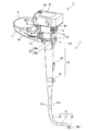
図1ないし図3に示す本実施形態の内視鏡装置は、内視鏡1と、被写体を照らす照明光を発する光源装置2と、内視鏡1で得た被写体の像を映像化して表示する映像表示装置3とを主要な構成要素として備えている。
内視鏡1は、この内視鏡1を把持するための把持部10と、先端を観察部位に挿入される挿入部11と、挿入部11の先端を湾曲操作するための操作部12とを備えている。把持部10は、棒状で親指とその他の指とで包み込むように握ることができる形に形成されている。挿入部11は、可撓性を有する細長い形状で、親指を上にして把持部10を握ったときに把持部10から下に垂れるように設けられており、操作部12は、把持部10を握った手の親指で操作できるように把持部10に隣接して設けられている。また、内視鏡1には、後述するイメージガイド11bによって導かれた像(光)を受光するCCD等の撮像素子4と、撮像素子4の受光部に結像する集光レンズ4aとが設けられている。なお、撮像素子4は、図に示すように映像表示装置3に近い位置に設けられる場合と、後述する先端部16に設けられる場合とがある。
[First Embodiment]
A first embodiment of the present invention will be described with reference to FIGS.
The endoscope apparatus of this embodiment shown in FIGS. 1 to 3 visualizes and displays an
The
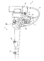
把持部10には、体液等の液体を吸引するための吸引口金13と、鉗子等の処置具を挿入するための鉗子挿入口14と、内視鏡1の水漏れ検査時に内視鏡1内部に空気を送るための通気口金15とが設けられている。吸引口金13には、図示しないチューブを介して吸引装置が接続されるようになっており、吸引装置を作動させることにより吸引口金13を通じて体液等を吸引することができるようになっている。通気口金15には、図示しないチューブを介して給気装置が接続されるようになっており、給気装置を作動させることにより通気口金15から内視鏡1に空気を送り込み、内視鏡1内部の水漏れ検査を行うことができるようになっている。また、把持部10には、映像表示装置3に表示されている映像を後述する画像記録装置32に記録させる画像記録スイッチ32bが設けられている。
The
挿入部11は、先端に位置する硬質な先端部16と、先端部16の後ろに連続して設けられた湾曲部17と、湾曲部17の後ろにさらに連続して設けられて把持部10に接続されたしなやかな可撓部18とを備えている。先端部16には、照明光に照らされた被写体からの反射光による像を結像する対物レンズ19と、照明光を出射する照明窓16aとが設けられている。挿入部11には、光源装置2から先端部16に照明光を導くライトガイド11aと、対物レンズ19に結像された像を撮像素子4に導くイメージガイド11bとが内蔵されている。
The
操作部12には、挿入部11に通された2本のワイヤ11cを介して湾曲部17を所望の方向に湾曲させるための湾曲操作レバー20が設けられている。湾曲操作レバー20は、把持部10を掴んだ親指の腹で操作される先端部20aと、先端部20aの一端に繋がる基端部20bとからなるL字形で、操作部12に設けられた軸12aに基端部20bを軸支されて上下に揺動可能に支持されている。
湾曲操作レバー20は、先端部20aを親指で上下に押し引きすることでいずれか一方のワイヤ11cに張力を、他方のワイヤ11cに推力を作用させて湾曲部17を自在に湾曲させることができるようになっている。
The
The
光源装置2は、光源ランプ21と、術者が任意に光源ランプ21を点灯/滅灯させるための手許スイッチ22と、光源ランプ21が発した照明光を集光する集光レンズ23とを備えている。また、光源装置2には、後述する給電ケーブル6を着脱可能に接続されるコネクタ2aが設けられている。光源ランプ21、手許スイッチ22およびコネクタ2aは、光源装置2に内蔵された給電ライン2bによって直列に接続されている。
光源ランプ21が発した照明光は、集光レンズ23によって集光され、ライトガイド11aに導かれて照明窓16aから出射され、体腔内を照明するようになっている。
The
Illumination light emitted from the
映像表示装置3は、内視鏡1を親指を上にして把持部10を握ったときに操作部12の上に着脱可能に取り付けられている。映像表示装置3には、被写体の観察像を映像化して表示させるLCD等の表示素子31と、被写体の像を記録する画像記録装置32と、撮像素子4で撮像された被写体の像を信号化して出力する撮像素子制御回路33と、撮像素子制御回路33から出力された信号を映像化して表示素子31に表示させる表示素子制御回路34とが設けられている。映像表示装置3には、光源装置2、撮像素子4、映像表示装置3の各部に電力を供給するバッテリ5が、交換可能に内蔵されている。バッテリ5には、繰り返し充電して使用することができる二次電池が使用されている。また、映像表示装置3には、表示素子31の起動スイッチ35が設けられている。
The
内視鏡1の上部にはブラケット1bが設けられ、映像表示装置3の下部にもブラケット3aが設けられており、これら2つのブラケット1b,3aは、締め付け用のネジ8によって締結されている。映像表示装置3は、ネジ8を緩めることにより画面の向きを湾曲操作レバー20側に傾斜させることができ、可動範囲内の所望の位置でネジ8を締めることにより固定することができるようになっている。
A
映像表示装置3と光源装置2とは、後述する給電ライン21aを内包する給電ケーブル6を介して接続されている。映像表示装置3と内視鏡1とは、後述する給電ライン4bおよび通信ラインS1を内包する集合ケーブル7を介して接続されている。給電ケーブル6および集合ケーブル7は、いずれも映像表示装置3側に固定され、先端にはそれぞれコネクタ6a,7aが設けられている。コネクタ6aは光源装置2のコネクタ2aに着脱可能に接続され、コネクタ7aは内視鏡1のコネクタ1aに着脱可能に接続されるようになっている。
The
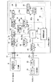
次に、内視鏡装置の機能ブロック図を図4に示す。同図に示すように、上記の内視鏡装置には、撮像素子4から映像表示装置3に伝送される映像信号(撮像素子4において信号化された像)の入力の有無を検出する第1の検出部41と、起動スイッチ35のON/OFFの状態を検出する第2の検出部42と、第1の検出部41、第2の検出部42の検出結果に基づいて光源装置2や表示素子31に対する電力供給を断ったり、起動スイッチ35の操作を無効にしたりする給電制御回路(制御部)43とが設けられている。また、内視鏡装置には、給電制御回路43によって駆動されることでバッテリ5から表示素子31、、画像記録装置32および表示素子制御回路34への電力供給経路(後述する給電ライン31a,32a,34a)を断続する電力供給スイッチ44と、同じく給電制御回路43によって駆動されることでバッテリ5から光源装置2への電力供給経路(後述する給電ライン21a)を断続する電力供給スイッチ45と、給電制御回路43によって駆動されることでバッテリ5から撮像素子4および撮像素子制御回路33への電力供給経路(後述する給電ライン4b,33a)を断続する電力供給スイッチ46とが設けられている。
Next, a functional block diagram of the endoscope apparatus is shown in FIG. As shown in the figure, the endoscope apparatus described above detects the presence / absence of an input of a video signal (an image signaled in the imaging device 4) transmitted from the imaging device 4 to the
撮像素子4とバッテリ5との間には、撮像素子4に電力を供給する給電ライン4bが設けられ、光源装置2とバッテリ5との間には、光源ランプ21に電力を供給する給電ライン21aが設けられている。同様に、第1の検出部41とバッテリ5との間には第1の検出部41に電力を供給する給電ライン41aが設けられ、撮像素子制御回路33とバッテリ5との間には撮像素子制御回路33に電力を供給する給電ライン33aが設けられ、表示素子制御回路34とバッテリ5との間には表示素子制御回路34に電力を供給する給電ライン34aが設けられ、表示素子31とバッテリ5との間には表示素子31に電力を供給する給電ライン31aが設けられている。さらに、画像記録装置32とバッテリ5との間には画像記録装置32に電力を供給する給電ライン32aが設けられ、第2の検出部42とバッテリ5との間には第2の検出部42に電力を供給する給電ライン42aが設けられ、給電制御回路43とバッテリ5との間には給電制御回路43に電力を供給する給電ライン43aが設けられている。
給電スイッチ44は給電ライン31a,32a,34aの途中に設けられ、給電スイッチ45は給電ライン21aの途中に設けられ、給電スイッチ46は給電ライン21a,33aの途中に設けられている。
A
The
撮像素子4と撮像素子制御回路33との間には、撮像素子4で取得された映像信号を撮像素子制御回路33に伝送する信号ラインS1が設けられ、撮像素子制御回路33と表示素子制御回路34との間には、撮像素子制御回路33に入力された映像信号を表示素子制御回路34に伝送する信号ラインS2が設けられ、表示素子制御回路34と表示素子31との間には、表示素子制御回路34に入力された映像信号を表示素子31に入力する信号ラインS3が設けられている。
第1の検出部41は、信号ラインS2の途中に設けられている。
Between the image sensor 4 and the image
The first detection unit 41 is provided in the middle of the signal line S2.
給電制御回路43と第1の検出部41との間には、第1の検出部41が出力した信号を給電制御回路43に伝送する信号ラインS4が設けられ、給電制御回路43と第2の検出部42との間には、第2の検出部42が出力した信号を給電制御回路43に伝送する信号ラインS5が設けられている。また、給電制御回路43と電力供給スイッチ44との間には、表示素子31への電力供給を断続するために給電制御回路43が出力した信号を電力供給スイッチ44に伝送する信号ラインS6が設けられ、給電制御回路43と電力供給スイッチ45との間には、光源ランプ21への電力供給を断続するために給電制御回路43が出力した信号を電力供給スイッチ45に伝送する信号ラインS7が設けられている。
A signal line S4 for transmitting a signal output from the first detection unit 41 to the power
さらに、起動スイッチ35と第2の検出部42との間には、起動スイッチ35のON/OFFの状態を示す信号を伝送する信号ラインS8が設けられ、給電制御回路43と起動スイッチ35との間には、起動スイッチ35の操作を無効にするために給電制御回路43が出力した信号を起動スイッチ35に伝送する信号ラインS9が設けられている。表示素子31と起動スイッチ35との間には、表示素子31を起動または停止させるための信号を伝送する信号ラインS10が設けられ、撮像素子制御回路33と画像記録装置32との間には、映像信号を画像記録装置32に伝送する信号ラインS10が設けられている。
Furthermore, a signal line S8 for transmitting a signal indicating the ON / OFF state of the
上記のように構成された内視鏡装置において実施される消費電力抑制の制御を、図5のフローチャートを用いて説明する。
内視鏡装置が起動されると、給電制御回路43は、まず、電力供給スイッチ44,45,46を閉じて撮像素子4、撮像素子制御回路33、表示素子制御回路34、表示素子31、画像記録装置32、光源装置2のそれぞれに対する電力供給路(給電ライン4b,33a,34a,31a,32a,21a)を確保する(ステップST1)。
電力供給スイッチ46を閉じても、集合ケーブル7が内視鏡1に接続されていない場合がある。そこで、給電制御回路33は、撮像素子4から映像表示装置3に対する映像信号の入力の有無を、第1の検出部41の検出結果に基づいて判別する(ステップST2)。
Control of power consumption suppression implemented in the endoscope apparatus configured as described above will be described with reference to the flowchart of FIG.
When the endoscope apparatus is activated, the power
Even when the
ステップST2において、第1の検出部41が、撮像素子4から映像表示装置3に対して映像信号の入力が有るとの検出結果を示す信号を出力した場合(集合ケーブル7が接続されている場合)でも、給電ケーブル6が、光源装置2に接続されていない場合がある。そこで、給電制御回路43は、光源装置2が駆動しているか否かを判別する(ステップST3)。
ステップST2において、第1の検出部41が、撮像素子4から映像表示装置3に対して映像信号の入力が無いとの検出結果を示す信号を出力した場合(集合ケーブル7が接続されていない場合)、給電制御回路43は、電力供給スイッチ44,45を開いて表示素子制御回路34、表示素子31、画像記録装置32および光源装置2に対する電力供給路(給電ライン34a,31a,32a,21a)を断ち(ステップST4)、さらに起動スイッチ35を無効にする(ステップST5)。
続いて、給電制御回路43は、処理の終了する外部命令の有無を判別し(ステップST6)、終了命令が有る場合は上記の処理を終了し、終了命令が無い場合はステップST2に戻って上記の処理を繰り返す。
In Step ST2, when the first detection unit 41 outputs a signal indicating a detection result indicating that a video signal is input from the imaging element 4 to the video display device 3 (when the
In Step ST2, when the first detection unit 41 outputs a signal indicating a detection result that there is no video signal input from the image sensor 4 to the video display device 3 (when the
Subsequently, the power
ステップST3において、光源装置2が駆動している場合(給電ケーブル6が接続されている場合)、給電制御回路43は、起動スイッチ35の操作が有効か無効かを判別する(ステップST7)。
ステップST3において、光源装置2が駆動していない場合(給電ケーブル6が接続されていない場合)、給電制御回路43は、上記のステップST4に移行する。
ステップST7において、起動スイッチ35の操作が有効である場合でも、起動スイッチ35が切られている、すなわちOFF状態にある場合があるので、給電制御回路43は、起動スイッチ35がON状態にあるかOFF状態にあるかを、第2の検出部42の検出結果に基づいて判別する(ステップST8)。
ステップST7において、起動スイッチ35の操作が無効である場合、給電制御回路43は、起動スイッチ35の操作を有効に切り替えたうえで(ステップST9)、ステップST8に移行する。
In step ST3, when the
In step ST3, when the
In step ST7, even if the operation of the
In step ST7, when the operation of the
ステップST8において、第2の検出部42が、起動スイッチ35がON状態にあるとの検出結果を示す信号を出力した場合、給電制御回路43は、電力供給スイッチ44,45が閉じられているか否かを判別する(ステップST10)。
ステップST8において、第2の検出部42が、起動スイッチ35がOFF状態にあるとの検出結果を示す信号を出力した場合、給電制御回路43は、上記のステップST4に移行する。
ステップST10において、電力供給スイッチ44,45が閉じられている場合、給電制御回路43は、上記のステップST6に移行する。
ステップST10において、電力供給スイッチ44,45が開かれている場合、給電制御回路43は、電力供給スイッチ44,45を閉じて表示素子制御回路34、表示素子31、画像記録装置32および光源装置2に対する電力供給路(給電ライン34a,31a,32a,21a)を確保したうえで(ステップST11)、上記のステップST6に移行し、終了命令が有る場合は上記の処理を終了し、終了命令が無い場合はステップST2に戻って上記の処理を繰り返す。
In Step ST8, when the
In Step ST8, when the
In step ST10, when the power supply switches 44 and 45 are closed, the power
In step ST10, when the power supply switches 44 and 45 are opened, the power
上記の内視鏡装置においては、撮像素子4から映像表示装置3に対して信号の入力が無い場合に、表示素子31に電力を供給しないようにしたり、光源装置2に電力を供給しないようにしたり、起動スイッチ35の操作を無効にしたり、光源装置2に電力を供給しないようにしたりすることで、無駄な電力消費が抑えられるので、可搬性を高めるべく小型のバッテリを搭載しても長時間の使用が可能になる。
In the endoscope apparatus described above, when no signal is input from the image sensor 4 to the
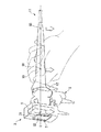
上記の内視鏡装置は、図6に示すように、把持部10を手で握り、親指を上にして内視鏡1を保持したとき、光源装置2を装着された内視鏡1の重心G1が、内視鏡1を把持した手の中に存在するとともに、その重心G1と映像表示装置3に内臓されたバッテリ5の重心G2とが、略鉛直方向に並び、仮想の鉛直線L上に存在するように、内視鏡1および映像表示装置3の各部の重量配分が調整されている。バッテリ5の重量は、バッテリ5を内臓しない状態の映像表示装置3の重量に比べてはるかに重く、バッテリ5を内臓した状態の映像表示装置3の重量バランスはほとんどバッテリ5の重量に依存しており、バッテリ5を内臓した状態の映像表示装置3の重心は、バッテリ5単体の重心にほぼ一致している。そのため、バッテリ5を内臓した状態の映像表示装置3の重心は、バッテリ5の重心G2と同一と見なせる。
また、内視鏡1から下方に垂れる挿入部11の重心G3は、内視鏡1を把持した手よりも下方に位置し、かつ鉛直線L上に存在している。
As shown in FIG. 6, the endoscope apparatus has a center of gravity of the
Further, the center of gravity G3 of the
また、上記の内視鏡装置は、図6または図7に示すように、把持部10を手で握って内視鏡1を保持し、把持部10を自転させるように操作したとき、その自転の中心となる軸線L上に、表示素子31の画面に表示される映像Eの中心が配置されるようになっている。
Further, as shown in FIG. 6 or FIG. 7, the endoscope apparatus described above holds the
上記のように構成された内視鏡装置においては、図6のようにして内視鏡装置を保持したとき、光源装置2を装着された内視鏡1の重心G1が内視鏡1を把持した手の中に存在し、さらにその重心G1と映像表示装置3の重心G2(バッテリ5の重心に等しい)とが、鉛直方向に沿う仮想線L上に並んで存在することにより、内視鏡1の把持部10を握る手には、手の中の内視鏡1を下向きに引っ張るような重力Fのみが作用し、手首を捻るような偶力は作用しない。内視鏡1を下向きに引っ張るように作用する重力Fは、手首の力ではなく上腕の筋肉で負担することになる。
In the endoscope apparatus configured as described above, when the endoscope apparatus is held as shown in FIG. 6, the center of gravity G1 of the
また、図8に示すように、把持部10を握る手の甲を上に向けるようにして内視鏡装置を保持したときには、内視鏡1を中心にして手の親指側に映像表示装置3が、小指側に挿入部11が位置する。両者には、それぞれの重心G1,G2,G3に下向きに重力が作用し、内視鏡1の重心G1を中心として仮想線Lがほぼ水平になるように内視鏡装置の左右(映像表示装置3側と挿入部11側)の重量バランスが釣り合うので、この場合も手首を捻るような偶力は作用しない。
Further, as shown in FIG. 8, when the endoscope apparatus is held with the back of the hand gripping the
したがって、内視鏡1を手で持ったとき、その手に手首を捻るような偶力が作用せず、手首に無理な負担がかからないので、使用中の手の負担を少なくし、長時間にわたって内視鏡装置を楽に使用することができる。
Therefore, when the
上記のように構成された内視鏡装置においては、挿入部11を観察部位に挿入する際、画面に表示された映像Eを見ながら、手に持った内視鏡1を自転させるように操作しても、術者が視点を置いた映像Eの中心が揺れ動くことがない。そのため、術者は視点を一点に留めて作業を進めることができ、疲労がたまり難い。
In the endoscope apparatus configured as described above, when the
したがって、手に持った内視鏡1を自転させるように操作しても、視点を置いた映像Eの中心が揺れ動くことがなく、術者は視点を一点に留めておくことができるので、使用中の目の負担が減少し、長時間にわたって内視鏡装置を楽に使用することができる。
なお、本実施形態においては既定の軸線Lに、表示素子31の画面に表示された映像Eの中心を合わせたが、表示素子31の画面の中心を合わせるようにしてもよい。映像Eは画面のほぼ中央に表示されるから、実質的に軸線Lと映像Eの中心が一致することになる。
また、把持部10の自転の中心は、個々の術者の技量やくせ等によって微妙に変化するので、内視鏡1に自転の中心を随時検出する手段を設け、その検出結果に基づいて表示素子31に表示させる映像Eの中心が随時変化する自転の中心に常に一致するように制御するようにしてもよい。
Therefore, even if the
In the present embodiment, the center of the image E displayed on the screen of the
In addition, since the center of rotation of the grasping
[第2の実施形態]
本発明の第2の実施形態を図9に示して説明する。なお、上記第1の実施形態にて既に説明した構成要素には同一符号を付して説明は省略する。
図9には、映像表示装置3の画面の向きを湾曲操作レバー20側に傾斜させた状態を示している。このように映像表示装置3を傾斜させた状態で把持部10を手で握り、親指を上にして内視鏡1を保持したときには、重心G1が内視鏡1を把持した手の中に存在し、さらに映像表示装置3の重心G2が、重心1を通る仮想線Lよりも、内視鏡1を把持した手の親指側にずれた位置に存在する。
[Second Embodiment]
A second embodiment of the present invention will be described with reference to FIG. In addition, the same code | symbol is attached | subjected to the component already demonstrated in the said 1st Embodiment, and description is abbreviate | omitted.
FIG. 9 shows a state in which the screen direction of the
本実施形態の内視鏡装置においては、内視鏡1の把持部10を握る手に、手の中の内視鏡1を下向きに引っ張るような重力Fの他に、内視鏡1を親指側に倒す方向に偶力Mが作用する。このときも、内視鏡1を下向きに引っ張るように作用する重力Fは手首の力ではなく上腕の筋肉で負担する。また、内視鏡1を親指側に倒す方向に作用する偶力Mについては、手首はその方向にはあまり自由度をもたないので、特に大きな力を加えなくても、偶力Mに抗して内視鏡1が正しい位置に保持される。
In the endoscope apparatus according to the present embodiment, in addition to the gravitational force F that pulls the
したがって、本実施形態の内視鏡装置によれば、内視鏡1を手で持ったとき、その手に手首を捻るような偶力が作用せず、手首に無理な負担がかからないので、使用中の手の負担を少なくし、長時間にわたって内視鏡装置を楽に使用することができる。
Therefore, according to the endoscope apparatus of the present embodiment, when the
本実施形態は、機器の構成としては上記第1の実施形態に等しく、映像表示装置3を傾斜させて固定し、映像表示装置3の重心G2の位置が変化した場合に成立する作用効果について説明しているが、本発明は、映像表示装置3を傾斜させずに固定した状態で、その重心G2の位置が仮想線Lよりも内視鏡1を把持した手の親指側にずれた位置になるように、映像表示装置3の各部の重量配分が調整されているものについても成立する。
This embodiment is the same as the first embodiment in terms of the configuration of the device, and describes the effects that are realized when the
本発明の内視鏡装置は、上記のような医療用だけでなく工業用にも好適に利用することが可能である。 The endoscope apparatus of the present invention can be suitably used not only for medical use as described above but also for industrial use.
1 内視鏡
2 光源装置
3 映像表示装置
4 撮像素子
5 バッテリ
10 把持部
11 挿入部
12 操作部
20 湾曲操作レバー
21 光源ランプ
31 表示素子
35 起動スイッチ
41 第1の検出部
42 第2の検出部
43 制御部
44,45 電力供給スイッチ
G1,G2,G3 重心
L 軸線
E 映像
DESCRIPTION OF
Claims (3)
前記被写体を照らす照明光を発する光源装置と、
前記内視鏡で得た前記被写体の像を映像化して表示する映像表示装置と、
前記撮像素子、前記光源装置ならびに前記映像表示装置に電力を供給するバッテリとを備える内視鏡装置であって、
前記内視鏡の重心と前記バッテリの重心とが、略鉛直方向に並んで存在するように配設され、
前記光源装置、前記映像表示装置および前記バッテリが前記内視鏡に装着されており、前記内視鏡を手に持つための把持部を手に持ち親指を上に向けて保持したとき、前記光源装置を装着された前記内視鏡の重心が前記把持部を把持した手の中に存在するように配設され、
前記バッテリが前記映像表示装置に内臓されており、
前記バッテリを内臓された前記映像表示装置の重心が、前記バッテリの重心とほぼ一致していることを特徴とする内視鏡装置。 An endoscope including an image sensor that captures an image of a subject;
A light source device that emits illumination light to illuminate the subject;
A video display device that visualizes and displays an image of the subject obtained by the endoscope;
An endoscope apparatus comprising: a battery that supplies power to the imaging element, the light source device, and the video display device,
The center of gravity of the endoscope and the center of gravity of the battery are arranged so as to be aligned in a substantially vertical direction,
The light source device, the video display device, and the battery are mounted on the endoscope, and when the grip portion for holding the endoscope is held in a hand and the thumb is held upward, the light source Arranged so that the center of gravity of the endoscope to which the device is attached is present in the hand holding the holding part,
The battery is built in the video display device;
An endoscope apparatus characterized in that a center of gravity of the video display device incorporating the battery substantially coincides with a center of gravity of the battery.
前記被写体を照らす照明光を発する光源装置と、
前記内視鏡で得た前記被写体の像を映像化して表示する映像表示装置と、
前記撮像素子、前記光源装置ならびに前記映像表示装置に電力を供給するバッテリとを備える内視鏡装置であって、
前記光源装置、前記映像表示装置および前記バッテリが前記内視鏡に装着されており、前記内視鏡を手に持つための把持部を手に持ち親指を上に向けて保持したとき、前記光源装置を装着された前記内視鏡の重心が前記把持部を把持した手の中に存在するように配設され、
前記バッテリの重心が、前記光源装置を装着された前記内視鏡の重心を通る仮想の鉛直線よりも、前記操作部の湾曲操作レバー側にずれた位置に存在するように配設され、
前記バッテリが前記映像表示装置に内臓されており、
前記バッテリを内臓された前記映像表示装置の重心が、前記バッテリの重心とほぼ一致していることを特徴とする内視鏡装置。 An endoscope including an image sensor that captures an image of a subject;
A light source device that emits illumination light to illuminate the subject;
A video display device that visualizes and displays an image of the subject obtained by the endoscope;
An endoscope apparatus comprising: a battery that supplies power to the imaging element, the light source device, and the video display device,
The light source device, the video display device, and the battery are mounted on the endoscope, and when the grip portion for holding the endoscope is held in a hand and the thumb is held upward, the light source Arranged so that the center of gravity of the endoscope to which the device is attached is present in the hand holding the holding part,
The center of gravity of the battery is disposed so as to be located at a position shifted toward the bending operation lever side of the operation unit from a virtual vertical line passing through the center of gravity of the endoscope to which the light source device is attached.
The battery is built in the video display device;
An endoscope apparatus characterized in that a center of gravity of the video display device incorporating the battery substantially coincides with a center of gravity of the battery.
Priority Applications (1)
| Application Number | Priority Date | Filing Date | Title |
|---|---|---|---|
| JP2003371738A JP4530642B2 (en) | 2003-10-31 | 2003-10-31 | Endoscope device |
Applications Claiming Priority (1)
| Application Number | Priority Date | Filing Date | Title |
|---|---|---|---|
| JP2003371738A JP4530642B2 (en) | 2003-10-31 | 2003-10-31 | Endoscope device |
Publications (2)
| Publication Number | Publication Date |
|---|---|
| JP2005131161A JP2005131161A (en) | 2005-05-26 |
| JP4530642B2 true JP4530642B2 (en) | 2010-08-25 |
Family
ID=34648309
Family Applications (1)
| Application Number | Title | Priority Date | Filing Date |
|---|---|---|---|
| JP2003371738A Expired - Fee Related JP4530642B2 (en) | 2003-10-31 | 2003-10-31 | Endoscope device |
Country Status (1)
| Country | Link |
|---|---|
| JP (1) | JP4530642B2 (en) |
Families Citing this family (8)
| Publication number | Priority date | Publication date | Assignee | Title |
|---|---|---|---|---|
| DK1874117T3 (en) | 2005-04-28 | 2013-09-23 | Viiv Healthcare Co | POLYCYCLIC CARBAMOYL PYRIDONE DERIVATIVES WITH HIV INTEGRASE INHIBITIVE ACTIVITY |
| JP4800695B2 (en) * | 2005-07-27 | 2011-10-26 | オリンパス株式会社 | Endoscope device |
| EP2484270B1 (en) | 2010-12-24 | 2014-03-12 | Olympus Corporation | Endoscopic device |
| EP2636358B1 (en) | 2010-12-24 | 2019-04-03 | Olympus Corporation | Endoscope apparatus |
| WO2012086064A1 (en) | 2010-12-24 | 2012-06-28 | オリンパス株式会社 | Endoscopic device |
| CN102711581B (en) | 2010-12-24 | 2014-01-29 | 奥林巴斯株式会社 | Endoscopic device |
| US8177710B1 (en) | 2011-08-02 | 2012-05-15 | Olympus Corporation | Endoscopic device |
| US8182416B1 (en) | 2011-08-02 | 2012-05-22 | Olympus Corporation | Endoscopic device |
Family Cites Families (7)
| Publication number | Priority date | Publication date | Assignee | Title |
|---|---|---|---|---|
| JPH119548A (en) * | 1997-06-25 | 1999-01-19 | Fuji Photo Optical Co Ltd | Portable electronic endoscope |
| JPH1156777A (en) * | 1997-08-25 | 1999-03-02 | Olympus Optical Co Ltd | Simplified endoscope |
| JP2997801B2 (en) * | 1997-09-18 | 2000-01-11 | オリンパス光学工業株式会社 | Endoscope device |
| JP2000116599A (en) * | 1998-10-13 | 2000-04-25 | Olympus Optical Co Ltd | Endoscopic instrument |
| JP2000131623A (en) * | 1998-10-28 | 2000-05-12 | Olympus Optical Co Ltd | Endoscopic device |
| JP4217357B2 (en) * | 1999-11-15 | 2009-01-28 | オリンパス株式会社 | Endoscopic imaging apparatus and endoscope system |
| DE10062737C1 (en) * | 2000-12-15 | 2002-10-31 | Sirona Dental Systems Gmbh | Hand instrument for medical, especially dental diagnosis |
-
2003
- 2003-10-31 JP JP2003371738A patent/JP4530642B2/en not_active Expired - Fee Related
Also Published As
| Publication number | Publication date |
|---|---|
| JP2005131161A (en) | 2005-05-26 |
Similar Documents
| Publication | Publication Date | Title |
|---|---|---|
| WO2005077252A1 (en) | Endoscope device | |
| US6554766B2 (en) | Endoscope device | |
| JP5030441B2 (en) | Endoscope device | |
| US6802809B2 (en) | Endoscope | |
| US7214183B2 (en) | Endoscope apparatus having an insertion channel | |
| JP5259113B2 (en) | Endoscope | |
| CN101267764B (en) | endoscopic device | |
| US20140012087A1 (en) | Endoscope | |
| US20120265007A1 (en) | Endoscope | |
| US20230126099A1 (en) | Endoscope system, controller, and stand | |
| JP4530642B2 (en) | Endoscope device | |
| WO2005082227A1 (en) | Endoscope and endoscope system | |
| CN100415153C (en) | endoscopic device | |
| JP4009600B2 (en) | Endoscope device | |
| JP2005131162A (en) | Endoscope | |
| EP1647221A1 (en) | Endoscope | |
| JP2005342400A (en) | Endoscope apparatus and endoscope system | |
| JP4343772B2 (en) | Endoscope device | |
| JP2003230535A (en) | Electric curving endoscope | |
| JP2002058629A (en) | Electronic endoscope | |
| JP2006149880A (en) | Endoscope operation unit | |
| JP3971400B2 (en) | Endoscope device | |
| JP2005211204A (en) | Endoscope apparatus | |
| JP3971399B2 (en) | Endoscope device | |
| JP2006043094A (en) | Endoscope apparatus |
Legal Events
| Date | Code | Title | Description |
|---|---|---|---|
| A621 | Written request for application examination |
Free format text: JAPANESE INTERMEDIATE CODE: A621 Effective date: 20060809 |
|
| A977 | Report on retrieval |
Free format text: JAPANESE INTERMEDIATE CODE: A971007 Effective date: 20090918 |
|
| A131 | Notification of reasons for refusal |
Free format text: JAPANESE INTERMEDIATE CODE: A131 Effective date: 20091006 |
|
| A521 | Request for written amendment filed |
Free format text: JAPANESE INTERMEDIATE CODE: A523 Effective date: 20091207 |
|
| A521 | Request for written amendment filed |
Free format text: JAPANESE INTERMEDIATE CODE: A821 Effective date: 20091208 |
|
| A131 | Notification of reasons for refusal |
Free format text: JAPANESE INTERMEDIATE CODE: A131 Effective date: 20100209 |
|
| A521 | Request for written amendment filed |
Free format text: JAPANESE INTERMEDIATE CODE: A523 Effective date: 20100326 |
|
| A521 | Request for written amendment filed |
Free format text: JAPANESE INTERMEDIATE CODE: A821 Effective date: 20100329 |
|
| TRDD | Decision of grant or rejection written | ||
| A01 | Written decision to grant a patent or to grant a registration (utility model) |
Free format text: JAPANESE INTERMEDIATE CODE: A01 Effective date: 20100601 |
|
| A01 | Written decision to grant a patent or to grant a registration (utility model) |
Free format text: JAPANESE INTERMEDIATE CODE: A01 |
|
| A61 | First payment of annual fees (during grant procedure) |
Free format text: JAPANESE INTERMEDIATE CODE: A61 Effective date: 20100608 |
|
| FPAY | Renewal fee payment (event date is renewal date of database) |
Free format text: PAYMENT UNTIL: 20130618 Year of fee payment: 3 |
|
| LAPS | Cancellation because of no payment of annual fees |