WO2018154814A1 - Biomaterial immobilizing method and uses thereof - Google Patents
Biomaterial immobilizing method and uses thereof Download PDFInfo
- Publication number
- WO2018154814A1 WO2018154814A1 PCT/JP2017/031281 JP2017031281W WO2018154814A1 WO 2018154814 A1 WO2018154814 A1 WO 2018154814A1 JP 2017031281 W JP2017031281 W JP 2017031281W WO 2018154814 A1 WO2018154814 A1 WO 2018154814A1
- Authority
- WO
- WIPO (PCT)
- Prior art keywords
- substrate
- immobilization
- agent
- substance
- biological material
- Prior art date
Links
Images


Classifications
-
- G—PHYSICS
- G01—MEASURING; TESTING
- G01N—INVESTIGATING OR ANALYSING MATERIALS BY DETERMINING THEIR CHEMICAL OR PHYSICAL PROPERTIES
- G01N33/00—Investigating or analysing materials by specific methods not covered by groups G01N1/00 - G01N31/00
- G01N33/48—Biological material, e.g. blood, urine; Haemocytometers
- G01N33/50—Chemical analysis of biological material, e.g. blood, urine; Testing involving biospecific ligand binding methods; Immunological testing
- G01N33/53—Immunoassay; Biospecific binding assay; Materials therefor
- G01N33/543—Immunoassay; Biospecific binding assay; Materials therefor with an insoluble carrier for immobilising immunochemicals
- G01N33/54313—Immunoassay; Biospecific binding assay; Materials therefor with an insoluble carrier for immobilising immunochemicals the carrier being characterised by its particulate form
- G01N33/54326—Magnetic particles
-
- B—PERFORMING OPERATIONS; TRANSPORTING
- B01—PHYSICAL OR CHEMICAL PROCESSES OR APPARATUS IN GENERAL
- B01J—CHEMICAL OR PHYSICAL PROCESSES, e.g. CATALYSIS OR COLLOID CHEMISTRY; THEIR RELEVANT APPARATUS
- B01J19/00—Chemical, physical or physico-chemical processes in general; Their relevant apparatus
- B01J19/0046—Sequential or parallel reactions, e.g. for the synthesis of polypeptides or polynucleotides; Apparatus and devices for combinatorial chemistry or for making molecular arrays
-
- G—PHYSICS
- G01—MEASURING; TESTING
- G01N—INVESTIGATING OR ANALYSING MATERIALS BY DETERMINING THEIR CHEMICAL OR PHYSICAL PROPERTIES
- G01N33/00—Investigating or analysing materials by specific methods not covered by groups G01N1/00 - G01N31/00
- G01N33/48—Biological material, e.g. blood, urine; Haemocytometers
- G01N33/50—Chemical analysis of biological material, e.g. blood, urine; Testing involving biospecific ligand binding methods; Immunological testing
- G01N33/53—Immunoassay; Biospecific binding assay; Materials therefor
- G01N33/543—Immunoassay; Biospecific binding assay; Materials therefor with an insoluble carrier for immobilising immunochemicals
- G01N33/54313—Immunoassay; Biospecific binding assay; Materials therefor with an insoluble carrier for immobilising immunochemicals the carrier being characterised by its particulate form
- G01N33/5432—Liposomes or microcapsules
-
- G—PHYSICS
- G01—MEASURING; TESTING
- G01N—INVESTIGATING OR ANALYSING MATERIALS BY DETERMINING THEIR CHEMICAL OR PHYSICAL PROPERTIES
- G01N37/00—Details not covered by any other group of this subclass
-
- B—PERFORMING OPERATIONS; TRANSPORTING
- B01—PHYSICAL OR CHEMICAL PROCESSES OR APPARATUS IN GENERAL
- B01J—CHEMICAL OR PHYSICAL PROCESSES, e.g. CATALYSIS OR COLLOID CHEMISTRY; THEIR RELEVANT APPARATUS
- B01J2219/00—Chemical, physical or physico-chemical processes in general; Their relevant apparatus
- B01J2219/00274—Sequential or parallel reactions; Apparatus and devices for combinatorial chemistry or for making arrays; Chemical library technology
- B01J2219/00277—Apparatus
- B01J2219/00351—Means for dispensing and evacuation of reagents
- B01J2219/00382—Stamping
-
- B—PERFORMING OPERATIONS; TRANSPORTING
- B01—PHYSICAL OR CHEMICAL PROCESSES OR APPARATUS IN GENERAL
- B01J—CHEMICAL OR PHYSICAL PROCESSES, e.g. CATALYSIS OR COLLOID CHEMISTRY; THEIR RELEVANT APPARATUS
- B01J2219/00—Chemical, physical or physico-chemical processes in general; Their relevant apparatus
- B01J2219/00274—Sequential or parallel reactions; Apparatus and devices for combinatorial chemistry or for making arrays; Chemical library technology
- B01J2219/00277—Apparatus
- B01J2219/00497—Features relating to the solid phase supports
- B01J2219/00527—Sheets
-
- B—PERFORMING OPERATIONS; TRANSPORTING
- B01—PHYSICAL OR CHEMICAL PROCESSES OR APPARATUS IN GENERAL
- B01J—CHEMICAL OR PHYSICAL PROCESSES, e.g. CATALYSIS OR COLLOID CHEMISTRY; THEIR RELEVANT APPARATUS
- B01J2219/00—Chemical, physical or physico-chemical processes in general; Their relevant apparatus
- B01J2219/00274—Sequential or parallel reactions; Apparatus and devices for combinatorial chemistry or for making arrays; Chemical library technology
- B01J2219/00583—Features relative to the processes being carried out
- B01J2219/00596—Solid-phase processes
-
- B—PERFORMING OPERATIONS; TRANSPORTING
- B01—PHYSICAL OR CHEMICAL PROCESSES OR APPARATUS IN GENERAL
- B01J—CHEMICAL OR PHYSICAL PROCESSES, e.g. CATALYSIS OR COLLOID CHEMISTRY; THEIR RELEVANT APPARATUS
- B01J2219/00—Chemical, physical or physico-chemical processes in general; Their relevant apparatus
- B01J2219/00274—Sequential or parallel reactions; Apparatus and devices for combinatorial chemistry or for making arrays; Chemical library technology
- B01J2219/00583—Features relative to the processes being carried out
- B01J2219/00603—Making arrays on substantially continuous surfaces
- B01J2219/00605—Making arrays on substantially continuous surfaces the compounds being directly bound or immobilised to solid supports
- B01J2219/00632—Introduction of reactive groups to the surface
- B01J2219/00637—Introduction of reactive groups to the surface by coating it with another layer
-
- B—PERFORMING OPERATIONS; TRANSPORTING
- B01—PHYSICAL OR CHEMICAL PROCESSES OR APPARATUS IN GENERAL
- B01J—CHEMICAL OR PHYSICAL PROCESSES, e.g. CATALYSIS OR COLLOID CHEMISTRY; THEIR RELEVANT APPARATUS
- B01J2219/00—Chemical, physical or physico-chemical processes in general; Their relevant apparatus
- B01J2219/00274—Sequential or parallel reactions; Apparatus and devices for combinatorial chemistry or for making arrays; Chemical library technology
- B01J2219/00583—Features relative to the processes being carried out
- B01J2219/00603—Making arrays on substantially continuous surfaces
- B01J2219/00646—Making arrays on substantially continuous surfaces the compounds being bound to beads immobilised on the solid supports
- B01J2219/00648—Making arrays on substantially continuous surfaces the compounds being bound to beads immobilised on the solid supports by the use of solid beads
-
- B—PERFORMING OPERATIONS; TRANSPORTING
- B01—PHYSICAL OR CHEMICAL PROCESSES OR APPARATUS IN GENERAL
- B01J—CHEMICAL OR PHYSICAL PROCESSES, e.g. CATALYSIS OR COLLOID CHEMISTRY; THEIR RELEVANT APPARATUS
- B01J2219/00—Chemical, physical or physico-chemical processes in general; Their relevant apparatus
- B01J2219/00274—Sequential or parallel reactions; Apparatus and devices for combinatorial chemistry or for making arrays; Chemical library technology
- B01J2219/00583—Features relative to the processes being carried out
- B01J2219/00603—Making arrays on substantially continuous surfaces
- B01J2219/00659—Two-dimensional arrays
-
- B—PERFORMING OPERATIONS; TRANSPORTING
- B01—PHYSICAL OR CHEMICAL PROCESSES OR APPARATUS IN GENERAL
- B01J—CHEMICAL OR PHYSICAL PROCESSES, e.g. CATALYSIS OR COLLOID CHEMISTRY; THEIR RELEVANT APPARATUS
- B01J2219/00—Chemical, physical or physico-chemical processes in general; Their relevant apparatus
- B01J2219/00274—Sequential or parallel reactions; Apparatus and devices for combinatorial chemistry or for making arrays; Chemical library technology
- B01J2219/00718—Type of compounds synthesised
- B01J2219/0072—Organic compounds
- B01J2219/00725—Peptides
-
- B—PERFORMING OPERATIONS; TRANSPORTING
- B01—PHYSICAL OR CHEMICAL PROCESSES OR APPARATUS IN GENERAL
- B01J—CHEMICAL OR PHYSICAL PROCESSES, e.g. CATALYSIS OR COLLOID CHEMISTRY; THEIR RELEVANT APPARATUS
- B01J2219/00—Chemical, physical or physico-chemical processes in general; Their relevant apparatus
- B01J2219/00274—Sequential or parallel reactions; Apparatus and devices for combinatorial chemistry or for making arrays; Chemical library technology
- B01J2219/00718—Type of compounds synthesised
- B01J2219/0072—Organic compounds
- B01J2219/0074—Biological products
-
- G—PHYSICS
- G01—MEASURING; TESTING
- G01N—INVESTIGATING OR ANALYSING MATERIALS BY DETERMINING THEIR CHEMICAL OR PHYSICAL PROPERTIES
- G01N33/00—Investigating or analysing materials by specific methods not covered by groups G01N1/00 - G01N31/00
- G01N33/48—Biological material, e.g. blood, urine; Haemocytometers
- G01N33/483—Physical analysis of biological material
- G01N33/487—Physical analysis of biological material of liquid biological material
- G01N33/49—Blood
Abstract
According to an aspect of the present invention, provided are a novel biomaterial immobilizing method having excellent immobilization ability, and uses thereof, the method being characterized in that: a immobilization carrier having a surface modification according to a biomaterial is used to immobilize a material to be immobilized, composed of a biomaterial; the material to be immobilized is pre-immobilized to the surface of the immobilization carrier; a layer for maintaining the immobilization carrier on a biomaterial immobilizing substrate is provided; and the immobilization carrier is stamped in the shape of a spot on the layer.
Description
本発明は、タンパク質、ペプチド、または核酸などの生体物質を基体上に安定に固定する生体物質固定化方法に関する。本発明は、特に、生体物質を固定した後、抗原抗体反応を発現させ、この抗原抗体反応を検査分析する方法に好適に使用可能である。特に、アレルギー検査および腫瘍マーカー検査等に用いられる抗原抗体反応を利用した検査診断用バイオチップに好適である。
The present invention relates to a biological material immobilization method for stably immobilizing a biological material such as a protein, peptide, or nucleic acid on a substrate. In particular, the present invention can be suitably used in a method for expressing an antigen-antibody reaction after immobilizing a biological substance, and examining and analyzing the antigen-antibody reaction. In particular, it is suitable for a biochip for test diagnosis using an antigen-antibody reaction used for allergy tests and tumor marker tests.
基体表面に小スポット状にDNAまたはタンパク質などの多種類の生体物質を被固定化物質として配したマイクロアレイ型計測法では、基体上に被固定化物質をスポットして固定する、あるいは基体上で所望の生体物質を合成する方法がある。
In the microarray measurement method in which a large number of biological substances such as DNA or protein are arranged as immobilized substances on the surface of the substrate in the form of small spots, the immobilized substance is spotted and immobilized on the substrate, or desired on the substrate. There is a method of synthesizing a biological material.
マイクロアレイ型計測を行う免疫測定のためのタンパクチップには、抗体又は抗原を何らかの形で基体上に固定化することが必要である。合成法が主流となっているDNAチップに対して、タンパクチップおよびペプチドチップでは合成法の適用は難しい。すなわち、現在、DNAチップでは、基体上で望みの配列のヌクレオチドを合成する方法が広く採用されている。しかし、タンパク質を基体上で合成することは現状では不可能である。ペプチドについては、基体上で合成は可能であるが、合成しただけでは充分な純度が得られない。そのため、タンパクチップおよびペプチドチップでは、精製タンパク質または精製ペプチドを基体表面上に直接スタンプする方法が主流である。
In a protein chip for immunoassay that performs microarray measurement, it is necessary to immobilize an antibody or antigen on a substrate in some form. The synthesis method is difficult to apply to protein chips and peptide chips, as opposed to DNA chips, which are mainly synthesized. That is, at present, a method for synthesizing nucleotides having a desired sequence on a substrate is widely used in DNA chips. However, it is currently impossible to synthesize proteins on a substrate. A peptide can be synthesized on a substrate, but sufficient purity cannot be obtained only by synthesis. Therefore, for protein chips and peptide chips, a method of stamping purified protein or purified peptide directly on the substrate surface is the mainstream.
このため、ガラスまたはプラスチック表面に易固定化のためのカルボキシ基(-COOH)あるいはアミノ基(-NH2)などの官能基を導入した基体が市販されている。また、光官能基を配して有機物は何でも固定できる光固定法も実用化されている。
For this reason, a substrate in which a functional group such as a carboxyl group (—COOH) or an amino group (—NH 2 ) for easy immobilization is introduced on the surface of glass or plastic is commercially available. In addition, a photofixation method in which a photofunctional group is arranged to fix any organic substance has been put into practical use.
前記のように、基体上に種々の固定化すべき生体物質を共有結合により固定化する方法が開発されてきた。また、非特異的吸着の防止効果に優れた生体物質固定化剤やそれを用いた生体物質固定化方法、生体物質固定化基体などの発明も行われてきたが、タンパクチップやペプチドチップで診断チップとしての信頼性を確立するには至っていない。タンパク質の三次元構造やそれに基づく生理機能を保持したまま、再現性良く固定するのが困難であることがその最大の理由である。加えて、タンパク質より格段に小さな分子であるペプチドでは、単に固定量を確保するだけでなく、その機能を一定に保つためには分子の配向をそろえて、すなわちペプチドのN末端またはC末端で固定する必要がある。また、平面基体上での反応系においては抗原抗体反応のように最終的にタンパク質との相互作用を利用して検出する際に、反応相手であるタンパク同士が互いにぶつかって反応を阻害する、いわゆる立体障害をできるだけ回避することも重要な要素となる。
なお、非特異的吸着とは、抗体分子がその相手以外の分子あるいはポリマーなどの有機物質や無機物質表面にも結合することを言う。化学反応ではないので吸着と言う。また、抗体分子がその相手の抗原分子と結合する反応を抗原抗体の特異的反応と言う。 As described above, methods for immobilizing various biological substances to be immobilized on a substrate by covalent bonds have been developed. In addition, inventions such as a biological material immobilizing agent excellent in the effect of preventing non-specific adsorption, a biological material immobilizing method using the same, and a biological material immobilizing substrate have been made. The reliability as a chip has not been established yet. The main reason is that it is difficult to fix with high reproducibility while maintaining the three-dimensional structure of protein and physiological functions based on it. In addition, peptides that are much smaller molecules than proteins are not only secured in a fixed amount, but in order to keep their functions constant, the molecules are aligned, that is, fixed at the N-terminus or C-terminus of the peptide. There is a need to. In addition, in a reaction system on a flat substrate, when the detection is finally performed using the interaction with a protein like an antigen-antibody reaction, the reaction partner proteins collide with each other to inhibit the reaction, so-called It is also important to avoid steric hindrance as much as possible.
Nonspecific adsorption means that antibody molecules bind to the surface of an organic substance or an inorganic substance such as a molecule or polymer other than the partner molecule. This is called adsorption because it is not a chemical reaction. A reaction in which an antibody molecule binds to its partner antigen molecule is called an antigen-antibody specific reaction.
基体上にタンパク質を固定化する方法の1つとして、光固定法が知られている(特許文献1)。これは基体上に予め光官能基をつけておき、固定化すべきタンパク質のアミノ酸側鎖と共有結合させることにより、基体上にタンパク質を固定化する。具体的には、アジド基などの光反応性官能基を持つポリマーを塗布したコート面にタンパク質等をスポットし、光照射してラジカル反応を起こし、被固定物質を共有結合するものである。この方法は被固定物質を選ばず何でも固定できるのが特徴であるが、光官能基の反応確率は100%でなく固定効率が高くないこと、ペプチドのような低分子を固定するには光官能基の密度が低いため適していないこと、また被固定分子の結合部位を選択できないことが問題であった。
As one method for immobilizing proteins on a substrate, a light immobilization method is known (Patent Document 1). In this method, a photofunctional group is previously provided on the substrate, and the protein is immobilized on the substrate by covalently bonding the amino acid side chain of the protein to be immobilized. Specifically, protein or the like is spotted on a coated surface coated with a polymer having a photoreactive functional group such as an azide group, and a radical reaction is caused by light irradiation to covalently bond an immobilized substance. This method is characterized in that it can fix anything regardless of the substance to be immobilized, but the photo-functional group reaction probability is not 100% and the immobilization efficiency is not high, and photofunctionality is necessary for immobilizing small molecules such as peptides. The problem is that the density of the group is low, which is not suitable, and the binding site of the immobilized molecule cannot be selected.
ペプチドのような低分子を固定する光固定法として、1分子中に少なくとも光反応基とエポキシ基のような室温反応性の官能基を有する固定化剤を利用する方法が提案されている(特許文献2)。光反応基とエポキシ基を有する固定化剤をスタンプ溶液に混ぜて使用することにより、基体面上でペプチドのアミノ基を固定化剤と常温で反応させ、さらに乾燥後、光固定させるものである。しかし、この方法は、ペプチド中のすべてのアミノ基と結合する可能性があるため、すなわちペプチドを構成するアミノ酸の一種のリシン(lysine)の持つ側鎖中のアミノ基とも結合してしまい、ペプチドN末端で固定化物質面に配向して固定されていることを保証できなかった。
As a light immobilization method for immobilizing a low molecule such as a peptide, a method using an immobilizing agent having at least a photoreactive group and a room temperature-reactive functional group such as an epoxy group in one molecule has been proposed (patent) Reference 2). By using an immobilizing agent having a photoreactive group and an epoxy group mixed with the stamp solution, the amino group of the peptide is reacted with the immobilizing agent at room temperature on the substrate surface, and further dried and photofixed. . However, this method has the possibility of binding to all amino groups in the peptide, that is, it binds to the amino group in the side chain of lysine, a kind of amino acid that constitutes the peptide. It could not be assured that the N-terminal is oriented and fixed on the surface of the immobilizing material.
前記の欠点を克服する方法として、非特許文献2の方法がある。これはN末端側のアミノ基をオキシアミノ基とすることにより、ペプチドの側鎖アミノ基と差別化しオキシアミノ基のみ基体上の官能基とエステル結合するような反応条件を可能としたものである。しかし、このためには基体表面にはオキシラン系の官能基をつけておく必要があり、さらに固定後、不要なオキシラン系の官能基を不活性化することが必要であり、また非特異的吸着によるバックグラウンドノイズの増加を防止する措置が必要となる。さらにチップの作製においては、前記のオキシアミノ基とオキシラン官能基の反応は、基体表面上にスタンプした被固定物質を含む液滴が乾燥するまでの数分の間に停止してしまうため、反応時間を十分とれないことが、反応確率が低い、すなわち固定量が少ない原因であった。
There is a method of Non-Patent Document 2 as a method of overcoming the above-mentioned drawbacks. This is because the amino group on the N-terminal side is changed to an oxyamino group so that the reaction condition can be differentiated from the side chain amino group of the peptide so that only the oxyamino group is ester-bonded to the functional group on the substrate. . However, for this purpose, it is necessary to attach an oxirane functional group to the substrate surface, and after fixing, it is necessary to inactivate unnecessary oxirane functional groups, and nonspecific adsorption. Measures to prevent background noise increase due to Furthermore, in the production of the chip, the reaction between the oxyamino group and the oxirane functional group is stopped within a few minutes until the droplet containing the immobilized substance stamped on the substrate surface is dried. Insufficient time was the cause of the low reaction probability, that is, the fixed amount was small.
これに対して、生体分子の固定用担体として微粒子を用いる方法もある。すなわち表面修飾をした微粒子に所望の反応によりタンパク分子等を固定する。微粒子上の反応は微粒子を含む色の変化等で観測する。このため1溶液1反応となり多種の反応の同時判定には不適であった。これを克服するため蛍光色素の色や強度を変えて粒子に含有させて、個々の粒子の識別を可能とした上で、フローサイトメトリー法を利用して多種反応判定を行う方法も開発されている。
On the other hand, there is a method using fine particles as a carrier for immobilizing biomolecules. That is, protein molecules and the like are immobilized on the surface-modified fine particles by a desired reaction. The reaction on the fine particles is observed by a change in color including the fine particles. For this reason, one solution is one reaction, which is not suitable for simultaneous determination of various reactions. In order to overcome this problem, a method has been developed in which the color and intensity of fluorescent dyes are changed and incorporated into particles to allow individual particles to be identified. Yes.
特許文献3には、微粒子として磁性微粒子を使い、磁性微粒子を保持層に固定する方法が記載されている。しかし、特許文献3に記載の技術は、検出のターゲットとする生体関連分子と磁性微粒子とを溶液中で相互作用させて、この生体関連分子を捕捉した後の磁性微粒子を、保持層に固定して蛍光検出するというものである。すなわち、生体関連分子を磁性微粒子に捕捉する反応自体は溶液中で行われるという点においては、微粒子を用いた従来技術との相違はない。また、特許文献3には、機能付与した(表面修飾を有する)磁性微粒子を所定の場所(スポット)に決められた間隔で固定する方法は開示されていない。
Patent Document 3 describes a method of using magnetic fine particles as fine particles and fixing the magnetic fine particles to the holding layer. However, in the technique described in Patent Document 3, a biologically relevant molecule as a detection target interacts with a magnetic fine particle in a solution, and the magnetic fine particle after capturing the biologically relevant molecule is fixed to a holding layer. And detecting fluorescence. That is, there is no difference from the prior art using fine particles in that the reaction for capturing biologically relevant molecules in magnetic fine particles is performed in solution. Further, Patent Document 3 does not disclose a method for fixing magnetic fine particles having a function (having a surface modification) at predetermined intervals (spots) at predetermined intervals (spots).
以上のように、被固定化物質を微粒子(ビーズとも言う)に固定し、溶液中で分析に供する方法がある。しかし、該微粒子を介在してスライドガラスまたはチップなどの基体上に固定するアレイ技術は、いまだ実用化されていない(非特許文献1)。
As described above, there is a method of immobilizing a substance to be immobilized on fine particles (also called beads) and subjecting it to analysis in a solution. However, an array technique for fixing the microparticles on a substrate such as a slide glass or a chip has not been put into practical use yet (Non-patent Document 1).
本発明の目的は、タンパク質、ペプチド、核酸及びこれらの混合物等である生体物質まで広く使用できる効率的な生体物質固定化方法を提供することにある。
An object of the present invention is to provide an efficient biological material immobilization method that can be widely used for biological materials such as proteins, peptides, nucleic acids, and mixtures thereof.
前記目的を達成するために、本発明の一態様に係る生体物質固定化方法は、生体物質からなる被固定化物質を固定化するために生体物質に応じた表面修飾を有する固定化担体を用い、前記固定化担体表面に前記被固定化物質を予め固定しておき、前記固定化担体を生体物質固定化用基体に保持するための層を設け、当該層の上に前記固定化担体をスポット状にスタンプすることを特徴とする。
In order to achieve the above object, a biological material immobilization method according to one aspect of the present invention uses an immobilization carrier having a surface modification according to a biological material in order to immobilize an immobilization material composed of the biological material. The substance to be immobilized is fixed in advance on the surface of the immobilization carrier, a layer for holding the immobilization carrier on the biological material immobilization substrate is provided, and the immobilization carrier is spotted on the layer. It is characterized by stamping in a shape.
本発明の一態様に係る基体は、生体物質を固定した基体であって、
生体物質である被固定化物質が表面に固定されている複数の粒子、及び、
複数の前記粒子それぞれと前記基体の表面との間に設けられ、複数の前記粒子それぞれを前記基体の表面に固定する固定化剤層
を備えてなる。 The substrate according to one embodiment of the present invention is a substrate on which a biological substance is fixed,
A plurality of particles to which an immobilized substance, which is a biological substance, is fixed on the surface; and
A fixing agent layer is provided between each of the plurality of particles and the surface of the substrate, and fixes each of the plurality of particles to the surface of the substrate.
本発明の一態様に係る生体物質との相互作用の評価方法は、前記基体に対してアプライされた(基体上に添加された)被験物質と、当該基体に固定された前記生体物質との相互作用を評価する工程を含む。
The method for evaluating an interaction with a biological material according to one embodiment of the present invention includes a test substance applied to the substrate (added to the substrate) and the biological material fixed to the substrate. A step of evaluating the action.
本発明の一態様に係る生体物質の固定化方法は、生体物質である被固定化物質が表面に固定されている複数の固定化担体を、固定化剤層を介して、基体の表面にスポット状に固定する工程を含む。
In the method for immobilizing a biological material according to one embodiment of the present invention, a plurality of immobilization carriers on which a material to be immobilized, which is a biological material, is immobilized on a surface are spotted on the surface of a substrate via an immobilizing agent layer. A step of fixing in a shape.
本発明の一態様に係る基体の製造方法は、前記基体の製造方法であって、複数の前記粒子を、前記固定化剤層を介して、前記基体の表面に固定する工程を含む。
The method for producing a substrate according to an aspect of the present invention is a method for producing the substrate, and includes a step of fixing a plurality of the particles to the surface of the substrate via the fixing agent layer.
本発明によれば、タンパク質、ペプチド、核酸及びこれらの混合物等である生体物質まで広く使用できる効率的な生体物質固定化方法を提供することができる。
According to the present invention, it is possible to provide an efficient biological material immobilization method that can be widely used for biological materials such as proteins, peptides, nucleic acids, and mixtures thereof.
(実施の形態の概要)
本願発明者らは、鋭意研究の結果、親水性ポリマーからなる非特異的吸着防止剤を基体上に塗布し、この上に、所望のタンパク質やペプチドなどの被固定化物質を所望の条件や配向で固定した微粒子(固定化担体)を、前記非特異的吸着防止剤を塗布したコート面にスポットした後、微粒子自体を固定する二段階固定法を発明し、再現性良くかつ高精度に固定が図れることを見出し、本発明を完成した。 (Outline of the embodiment)
As a result of diligent research, the inventors of the present application applied a nonspecific adsorption inhibitor made of a hydrophilic polymer on a substrate, and a substance to be immobilized, such as a desired protein or peptide, on the desired condition or orientation. Invented a two-stage fixing method in which the fine particles (immobilized carrier) fixed instep 1 are spotted on the coated surface coated with the non-specific adsorption inhibitor, and then fixed themselves with high reproducibility and high accuracy. As a result, the present invention has been completed.
本願発明者らは、鋭意研究の結果、親水性ポリマーからなる非特異的吸着防止剤を基体上に塗布し、この上に、所望のタンパク質やペプチドなどの被固定化物質を所望の条件や配向で固定した微粒子(固定化担体)を、前記非特異的吸着防止剤を塗布したコート面にスポットした後、微粒子自体を固定する二段階固定法を発明し、再現性良くかつ高精度に固定が図れることを見出し、本発明を完成した。 (Outline of the embodiment)
As a result of diligent research, the inventors of the present application applied a nonspecific adsorption inhibitor made of a hydrophilic polymer on a substrate, and a substance to be immobilized, such as a desired protein or peptide, on the desired condition or orientation. Invented a two-stage fixing method in which the fine particles (immobilized carrier) fixed in
すなわち、本発明は、親水性ポリマーからなる非特異的吸着防止剤を塗布し非特異的吸着を防止した基体面の上に、前もって十分な反応時間を与えてタンパク質あるいはペプチドをその表面に固定した微粒子と、1分子中に2つの光反応基を有する光架橋剤とを混合してあるいは重ねてスポットする二段階の物質固定化方法を提供する。
That is, in the present invention, a protein or peptide is immobilized on the surface of the substrate surface coated with a non-specific adsorption inhibitor made of a hydrophilic polymer to prevent non-specific adsorption so as to give a sufficient reaction time in advance. Provided is a two-stage substance immobilization method in which fine particles and a photocrosslinking agent having two photoreactive groups in one molecule are mixed or overlapped.
従来の固定化技術は、基体(生体物質固定化用基体)表面にスポットした被固定化物質を含む液滴が乾燥するまでの短い時間内に、例えばエステル結合などの所望の化学反応をおこし、基体への結合を行う一段階の方法であった。
これに対して、予め溶液反応で被固定化物質を微粒子に固定した後、光架橋剤で微粒子を基体に固定する本二段階法は、適正な条件下で再現性良く反応させることで、固定率を安定させ、固定密度を上げることができる。 In the conventional immobilization technique, a desired chemical reaction such as an ester bond is performed within a short time until the droplet containing the substance to be immobilized spotted on the surface of the substrate (substrate for immobilizing biological material) dries. It was a one-step method for bonding to the substrate.
In contrast, this two-step method, in which the substance to be immobilized is fixed to the microparticles in advance by a solution reaction, and then the microparticles are fixed to the substrate with a photocrosslinking agent, is fixed by reacting with good reproducibility under appropriate conditions. The rate can be stabilized and the fixed density can be increased.
微粒子径は特に限定されないが、好ましくは数100μm以下、より好ましくは5μm以下であり、タンパク質に比べて圧倒的に大きく、光架橋剤の密度を過度に高くすることなく確実に固定が可能となる。また、微粒子は、有機微粒子、無機微粒子、または磁性微粒子などであり得る。一例として、微粒子として、2.8μm径のDynabeads(登録商標)などを使用することができる。なお、タンパク質やペプチドなどの被固定化物質の種類によって、固定量、安定性、および/または再現性が最適となる微粒子を選択すればよい。
Although the particle size is not particularly limited, it is preferably several 100 μm or less, more preferably 5 μm or less, which is overwhelmingly larger than that of protein, and can be reliably fixed without excessively increasing the density of the photocrosslinking agent. . The fine particles may be organic fine particles, inorganic fine particles, magnetic fine particles, or the like. As an example, Dynabeads (registered trademark) having a diameter of 2.8 μm can be used as the fine particles. In addition, what is necessary is just to select the microparticles | fine-particles which the amount of fixation, stability, and / or reproducibility become the optimal according to the kind of to-be-immobilized substances, such as protein and a peptide.
微粒子担体表面へのタンパク質またはペプチドの固定条件と、微粒子担体の基体表面への固定条件とは別個のものであり、それぞれを最適化できる。
The conditions for fixing the protein or peptide to the surface of the fine particle carrier and the conditions for fixing the fine particle carrier to the substrate surface are different, and each can be optimized.
微粒子は反応操作がし易く、抗体をFc領域で微粒子上に配向させて固定することや、ペプチドを末端特異的に固定することが可能であり、従来の固定法の弱点を克服できる。したがって、本発明では、生体物質であるタンパク質やペプチドのような被固定化物質を基体上に固定するにあたり、直接被固定化物質を基体表面に固定するのではなく、微粒子の担体(ビーズ担体)を介在させることによって、被固定化物質と担体との固定化の反応条件および担体と基体との固定化の反応条件をそれぞれ最適化することができるようになった。これにより、タンパク質の三次元構造やそれに基づく生理機能を保持したまま、再現性良く固定したり、ペプチドで分子の配向をそろえて固定したりすることも可能となる。よって、タンパクチップやペプチドチップにおいて診断チップとしての信頼性を向上させることができる。また、微粒子表面を利用することで、固定化面積を大幅に増加させる効果や、前記立体障害、すなわちタンパク質同士によるペプチド結合反応の阻害を、微粒子が曲面を持つことにより隣接するペプチドに結合するタンパク分子間にわずかな角度のずれが生じて低減される効果が期待できる。
The microparticles are easy to react and can be immobilized by aligning the antibody on the microparticles in the Fc region, and the peptide can be immobilized specifically at the terminal, thus overcoming the weaknesses of conventional immobilization methods. Therefore, in the present invention, when immobilizing a substance to be immobilized such as a protein or peptide that is a biological substance on a substrate, the substance to be immobilized is not directly immobilized on the surface of the substrate, but a fine particle carrier (bead carrier). By interposing, the reaction conditions for the immobilization of the substance to be immobilized and the carrier and the reaction conditions for the immobilization of the carrier and the substrate can be optimized. As a result, it is possible to fix the protein with good reproducibility while maintaining the three-dimensional structure of the protein and physiological functions based on the protein, and to fix the molecule with the same molecular orientation. Therefore, the reliability as a diagnostic chip in a protein chip or a peptide chip can be improved. In addition, by using the surface of the fine particles, the protein that binds to adjacent peptides due to the curved surface of the fine particles has the effect of greatly increasing the immobilization area and the steric hindrance, that is, inhibition of the peptide binding reaction between proteins. It can be expected that a slight angle shift occurs between the molecules and the effect is reduced.
図3に、固定化された生体物質を検出するプロセスの一例を示す。具体例としてアレルギー診断チップにおいて、抗原抗体反応によってアレルゲンを検出し解析するプロセスを示す。
図3において、先ず、予め複数種のアレルゲンをスポットしておいた診断チップに血液検体(全血、血清、血漿いずれも可)を注入する。そして所定時間反応させた後、洗浄する。この例では、特異的IgE抗体AがアレルゲンAに反応し、特異的IgE抗体CはアレルゲンA,Bに反応していないことを示している。洗浄の目的は、反応していない特異的IgE抗体Cを除去するためである。次に、IgE抗体を認識する酵素標識2次抗体を該チップに注入し、所定時間反応させる。反応後、IgE抗体と結合していない2次抗体を除去するために洗浄する。その後、化学発光試薬を該チップに注入する。カメラにより、スポットの発光像を撮影し解析する。得られる発光信号強度は、抗原抗体反応の強度に比例するので、アレルギーに感作している度合を計測することができる。なお、生体物質の検出プロセスは、図3に示した方法によらず、適宜最適な方法を選択できる。 FIG. 3 shows an example of a process for detecting the immobilized biological material. As a specific example, a process for detecting and analyzing an allergen by an antigen-antibody reaction in an allergy diagnostic chip is shown.
In FIG. 3, first, a blood sample (whole blood, serum, or plasma is acceptable) is injected into a diagnostic chip on which a plurality of types of allergens are spotted in advance. Then, after reacting for a predetermined time, washing is performed. This example shows that specific IgE antibody A reacts with allergen A, and specific IgE antibody C does not react with allergens A and B. The purpose of washing is to remove non-reacting specific IgE antibody C. Next, an enzyme-labeled secondary antibody that recognizes an IgE antibody is injected into the chip and allowed to react for a predetermined time. After the reaction, washing is performed to remove the secondary antibody not bound to the IgE antibody. Thereafter, a chemiluminescent reagent is injected into the chip. The light emission image of the spot is taken and analyzed by the camera. Since the intensity of the luminescent signal obtained is proportional to the intensity of the antigen-antibody reaction, the degree of sensitization to allergy can be measured. In addition, the detection method of a biological substance can select the optimal method suitably not depending on the method shown in FIG.
また、微粒子表面には、タンパク質またはペプチドを既存の種々の方法で固定することができる。例えば、市販の微粒子表面をカルボキシ基、アミノ基またはエポキシ基などで修飾した微粒子(ビーズとも言う)を用いてもよい。
Also, proteins or peptides can be immobilized on the surface of the fine particles by various existing methods. For example, fine particles (also referred to as beads) obtained by modifying the surface of commercially available fine particles with a carboxy group, an amino group or an epoxy group may be used.
自動ペプチド合成機に用いられているビーズも、合成終了後、未反応物を洗浄除去した後、ペプチド担体微粒子としてそのまま利用することもできる。
The beads used in the automatic peptide synthesizer can also be used as they are as peptide carrier fine particles after the unreacted product is washed away after the synthesis is completed.
微粒子表面をエポキシ化あるいはN-ヒドロキシスクシンイミド(NHS)-エステル化して、オキシアミノ化ペプチドと反応させればN末端選択的な固定も可能となる。また、ストレプトアビジンあるいはニュートロアビジンを表面に結合した微粒子をN末端ビオチン化したペプチドと反応させることで、効率良くN末端特異的な固定ができる。
If the fine particle surface is epoxidized or N-hydroxysuccinimide (NHS) -esterified and reacted with an oxyaminated peptide, N-terminal selective fixation becomes possible. Further, by reacting microparticles having streptavidin or neutroavidin bound to the surface with an N-terminal biotinylated peptide, N-terminal specific fixation can be carried out efficiently.
表面にアルキンを導入した微粒子とN末端アジド化ペプチド、もしくは表面にアジド基を導入した微粒子とN末端アルキン化ペプチドを組み合わせることにより、クリック・ケミストリーを利用した、N末端特異的な共有結合でペプチドを固定することができる。
Peptide with N-terminal specific covalent bond using click chemistry by combining microparticles with alkyne introduced on surface and N-terminal azido peptide, or microparticles with azido group introduced on surface and N-terminal alkyne peptide Can be fixed.
前記の非特異的吸着防止剤は、親水性の性質を有することが必須である。もし疎水性の場合、疎水基に余分のタンパク質が吸着して検査分析精度を損なう。
It is essential that the nonspecific adsorption inhibitor has hydrophilic properties. If it is hydrophobic, the excess protein is adsorbed on the hydrophobic group, which impairs the accuracy of test analysis.
本発明によれば、固定化すべき生体物質を共有結合により安定に固定化することができる。本発明の方法を用いてタンパク質を固定化すると、固定化表面積を大幅に増やして立体障害を防ぐとともに、機能を保持した状態で固定することができ、抗原抗体反応や酵素反応など、タンパク質の機能を利用した感度の高い分析が可能となる。また、ペプチドをN末端のみで確実に固定できる。さらに、非特異的吸着が効果的に防止され、高精度の検査分析が可能となる。よって、高感度で信号/ノイズ(S/N)比の高い生体物質固定化基体が得られる。ここで言う固定化とは、微粒子と基体表面(好ましくは非特異的吸着防止層)との間で架橋剤(好ましくは光架橋剤)等の介在により、共有結合等の強い化学結合が形成されていることを言い、水素結合等の弱い化学結合およびファンデルワールス力等の物理吸着とは区別される。また被固定化物質を基体や非特異的吸着防止層と光架橋剤から成るコート層に機械力学的に埋め込む方式とも異なる。
According to the present invention, the biological substance to be immobilized can be stably immobilized by covalent bonding. When the protein is immobilized using the method of the present invention, the immobilization surface area can be greatly increased to prevent steric hindrance and the function can be immobilized while retaining the function, such as antigen-antibody reaction and enzyme reaction. This makes it possible to perform highly sensitive analysis using. In addition, the peptide can be reliably fixed only at the N-terminus. Furthermore, non-specific adsorption is effectively prevented, and highly accurate inspection analysis is possible. Therefore, a biological material-immobilized substrate having a high sensitivity and a high signal / noise (S / N) ratio can be obtained. The term “immobilization” as used herein means that a strong chemical bond such as a covalent bond is formed between a fine particle and a substrate surface (preferably a nonspecific adsorption-preventing layer) by interposing a crosslinking agent (preferably a photocrosslinking agent). It is distinguished from weak chemical bonds such as hydrogen bonds and physical adsorption such as van der Waals forces. Further, the method is different from the method in which the substance to be immobilized is mechanically embedded in a substrate or a coating layer composed of a nonspecific adsorption preventing layer and a photocrosslinking agent.
(本発明の一態様)
したがって、本発明の一態様に係る生体物質固定化方法は、生体物質からなる被固定化物質を固定化するために生体物質に応じた表面修飾を有する固定化担体を用い、前記固定化担体表面に前記被固定化物質を予め固定しておき、前記固定化担体を生体物質固定化用基体に保持するための層を設け、当該層の上に前記固定化担体をスポット状にスタンプすることを特徴とする。なお、「スタンプする」は「スポットする」と言い換え得る。 (One embodiment of the present invention)
Therefore, the biological material immobilization method according to one aspect of the present invention uses an immobilization carrier having a surface modification according to a biological material in order to immobilize an immobilization material composed of the biological material, and the surface of the immobilization carrier. The immobilization substance is fixed in advance, a layer for holding the immobilization carrier on the biological substance immobilization substrate is provided, and the immobilization carrier is stamped on the layer in a spot shape. Features. Note that “stamping” can be rephrased as “spotting”.
前記生体物質固定化方法の一態様は、複数の前記固定化担体に互いに異なる生体物質を予め固定しておき、前記層の上の互いに異なる位置に当該複数の固定化担体をスポット状にスタンプすることを特徴とする。このような態様によれば、個別の判定機能を付与した前記固定化担体、例えば、個別のアレルゲンを結合した固定化担体をスポット状にスタンプすることにより、同時に多種のアレルギー検査結果を患者に提供することができる。
In one aspect of the biological material immobilization method, different biological materials are immobilized in advance on the plurality of immobilization carriers, and the plurality of immobilization carriers are stamped in different positions on the layer. It is characterized by that. According to such an aspect, a variety of allergy test results can be provided to the patient at the same time by stamping the immobilization carrier provided with individual determination functions, for example, the immobilization carrier combined with individual allergens in a spot shape. can do.
前記生体物質固定化方法の一態様は、前記固定化担体として、有機微粒子または無機微粒子、あるいは磁性微粒子を用いることを特徴とする。このような態様によれば、前記固定化担体として、有機微粒子または無機微粒子、あるいは磁性微粒子を用いることで、固定化担体への生体物質の固定と、固定化担体の当該層への固定との二つの固定化工程を分けて行うため、それぞれの反応条件を最適化できるので、高固定量、高安定性を保証し、再現性良く固定できる。
One aspect of the biological material immobilization method is characterized by using organic fine particles, inorganic fine particles, or magnetic fine particles as the immobilization carrier. According to such an aspect, by using organic fine particles, inorganic fine particles, or magnetic fine particles as the immobilization carrier, it is possible to fix the biological material to the immobilization carrier and immobilize the immobilization carrier to the layer. Since the two immobilization steps are carried out separately, each reaction condition can be optimized, so that a high fixation amount and high stability can be ensured, and fixation can be performed with good reproducibility.
前記生体物質固定化方法の一態様は、前記固定化担体を生体物質固定化用基体に固定化する方法として、1分子中に少なくとも2個の光反応基を有する光架橋剤を用いることを特徴とする。このような態様によれば、1分子中に少なくとも2個の光反応基を有する光架橋剤を架橋剤として用いることで、光を照射する簡単な操作で共有結合を形成でき、当該層と固定化担体を安定に固定できる。
In one aspect of the biological material immobilization method, a photocrosslinking agent having at least two photoreactive groups in one molecule is used as a method of immobilizing the immobilization carrier on a biological material immobilization substrate. And According to such an embodiment, by using a photocrosslinking agent having at least two photoreactive groups in one molecule as a crosslinking agent, a covalent bond can be formed by a simple operation of irradiating light, and the layer is fixed. The immobilized carrier can be fixed stably.
前記生体物質固定化方法の一態様は、前記固定化担体を前記生体物質固定化用基体に保持するための層の上に、当該層と前記固定化担体とを架橋する架橋剤及び前記固定化担体をスポット状にスタンプする方法として、前記架橋剤と前記固定化担体を混合した混合液をスタンプする混合スタンプ法、または、先ず前記架橋剤をスタンプし、次に前記固定化担体をスタンプする分離スタンプ法、を採用することを特徴とする。このような態様によれば、混合スタンプ法と分離スタンプ法の両者を選択することができる。混合スタンプ法は、工程が簡略で、スポッタの精度に依存しない。一方、分離スタンプ法は、高精度のスポッタにより、スポット形状の均一性が得られ、撮像品質を高めることができる。
One aspect of the biological material immobilization method includes a cross-linking agent that crosslinks the layer and the immobilization carrier on the layer for holding the immobilization carrier on the biological material immobilization substrate, and the immobilization. As a method of stamping the carrier in a spot shape, a mixed stamp method in which a mixed liquid in which the crosslinking agent and the immobilization carrier are mixed is stamped, or separation in which the crosslinking agent is first stamped and then the immobilization carrier is stamped. The stamp method is employed. According to such an aspect, both the mixed stamp method and the separation stamp method can be selected. The mixed stamp method has a simple process and does not depend on the accuracy of the spotter. On the other hand, in the separation stamp method, the spot shape uniformity can be obtained by a high-precision spotter, and the imaging quality can be improved.
前記生体物質固定化方法の一態様は、前記固定化担体を前記生体物質固定化用基体に保持するための層として、水溶性ポリマーを塗布したことを特徴とする。このような態様によれば、親水性の非特異的吸着防止剤を使用するので、疎水性の非特異的吸着防止剤を使用する場合に比べて、余分なタンパク質が捕捉されることを防止でき、検査分析精度を向上させることができる。
One aspect of the biological material immobilization method is characterized in that a water-soluble polymer is applied as a layer for holding the immobilization carrier on the biological material immobilization substrate. According to such an embodiment, since a hydrophilic non-specific adsorption inhibitor is used, excess protein can be prevented from being captured as compared with the case of using a hydrophobic non-specific adsorption inhibitor. The inspection analysis accuracy can be improved.
次に図面を参照しながら、本発明の実施の形態の具体例(以下、実施例と記載する)を説明するが、本発明は以下の実施例に限定されるものではない。
Next, specific examples of embodiments of the present invention (hereinafter referred to as examples) will be described with reference to the drawings, but the present invention is not limited to the following examples.
生体物質を固定した微粒子を、光架橋剤(固定化剤)を用いて基体に固定する光固定法の実施例について説明する。図1に基体とその表面に作製する層構成を示す。
An example of a light fixing method in which fine particles on which a biological substance is fixed is fixed to a substrate using a photocrosslinking agent (fixing agent) will be described. FIG. 1 shows the substrate and the layer structure produced on the surface thereof.
基体の材質は特に限定されず、マイクロプレート等で広く用いられているポリスチレンをはじめ、アクリル、ポリカーボネート、ポリエチレンテレフタレート、ポリプロピレン、シクロオレフィンポリマー(COP)、およびシクロオレフィンコポリマー(COC)等の光透過性樹脂を例示することができる。また、ガラス等を用いることもできる。
The material of the substrate is not particularly limited, and light transmittance such as polystyrene, acrylic, polycarbonate, polyethylene terephthalate, polypropylene, cycloolefin polymer (COP), and cycloolefin copolymer (COC) widely used in microplates, etc. Resins can be exemplified. Glass or the like can also be used.
非特異的吸着防止剤として使用可能な水溶性ポリマーとしては、一例としてポリエチレングリコール(PEG)メタクリレートを使用することができる。非特異的吸着防止のための水溶性ポリマーは、それ自体公知であり、公知の製造方法により製造可能であり、また、市販されているものもある。また非特異的吸着防止層の形成法についても公知である(例えば特許文献1)。
As a water-soluble polymer that can be used as a non-specific adsorption inhibitor, polyethylene glycol (PEG) methacrylate can be used as an example. Water-soluble polymers for preventing non-specific adsorption are known per se, can be produced by known production methods, and some are commercially available. Moreover, the formation method of a nonspecific adsorption | suction prevention layer is also well-known (for example, patent document 1).
架橋剤として、1分子中に少なくとも2個の光反応基を有する光架橋剤を用いることが好ましい。光を照射する簡単な操作で共有結合を形成でき、固定化担体を生体物質固定化用基体に保持するための層と微粒子(固定化担体)とを安定に固定できる。光架橋剤が有する光反応基の好ましい例としてアジド基(-N3)があり、これを2個持つ分子としてジアジドスチルベンが挙げられる。本発明に用いられる光架橋剤のうち、特に好ましいのは水溶性のものである。ここで水溶性とは、0.5mM以上、好ましくは2mM以上の濃度の水溶液を与えることができることを意味する。光架橋剤の使用時の濃度は、特に限定されないが、0.01mg/mL~1g/mLが好ましく、0.2mg/mL~0.2g/mLがより好ましい。
As a crosslinking agent, it is preferable to use a photocrosslinking agent having at least two photoreactive groups in one molecule. A covalent bond can be formed by a simple operation of irradiating light, and the layer for holding the immobilization carrier on the biological material immobilization substrate and the fine particles (immobilization carrier) can be stably immobilized. A preferred example of the photoreactive group possessed by the photocrosslinking agent is an azide group (—N 3 ), and an example of a molecule having two of these is diazidostilbene. Of the photocrosslinking agents used in the present invention, particularly preferred are water-soluble ones. Here, water-soluble means that an aqueous solution having a concentration of 0.5 mM or more, preferably 2 mM or more can be provided. The concentration of the photocrosslinking agent when used is not particularly limited, but is preferably 0.01 mg / mL to 1 g / mL, and more preferably 0.2 mg / mL to 0.2 g / mL.
本発明により固定化される生体物質は特に限定されないが、タンパク質、ペプチド、核酸、脂質、糖などを例示することができる。なお、「ペプチド」とは、2個以上のアミノ酸がペプチド結合によって結合した化合物を指す。一例において、構成アミノ酸残基数がおよそ50以下のポリペプチドであり得る。また、一例において、「ペプチド」は、「ポリペプチド」または「タンパク質」とも換言し得る。「ペプチド」は、アミノ酸がペプチド結合してなる構造以外に、さらに、例えば、糖鎖またはイソプレノイド基などの構造を含んでいてもよい。
The biological material immobilized by the present invention is not particularly limited, and examples thereof include proteins, peptides, nucleic acids, lipids, sugars and the like. “Peptide” refers to a compound in which two or more amino acids are bound by peptide bonds. In one example, it may be a polypeptide having approximately 50 or fewer constituent amino acid residues. In one example, “peptide” may also be referred to as “polypeptide” or “protein”. The “peptide” may further include, for example, a structure such as a sugar chain or an isoprenoid group, in addition to a structure in which an amino acid is a peptide bond.
本発明の光反応基として用いられるアジド基あるいはジアジリン基は、光を照射することにより窒素分子が離脱すると共に窒素ラジカルあるいは炭素ラジカルが生じ、この窒素ラジカルあるいは炭素ラジカルは、アミノ基やカルボキシ基等の官能基のみならず、有機化合物を構成する炭素原子とも結合することが可能であるので、ほとんどの有機物と架橋することができる。したがって、微粒子表面を構成する炭素原子と、非特異的吸着防止層を構成するポリマーやプラスチックなどの基体表面に存在する炭素原子とを結合することができる。
The azido group or diazirine group used as the photoreactive group of the present invention is a nitrogen radical or a carbon radical that is generated upon irradiation with light and a nitrogen radical or a carbon radical. The nitrogen radical or carbon radical is an amino group, a carboxy group, or the like. Since it is possible to bond not only to the functional group but also to the carbon atom constituting the organic compound, it can be crosslinked with most organic substances. Therefore, it is possible to bond carbon atoms constituting the surface of the fine particles and carbon atoms present on the surface of the substrate such as a polymer or plastic constituting the nonspecific adsorption preventing layer.
図1に示す層の作製手順を、以下に示す。
1)先ず、基体を準備する。基体の材料は、前記の材料を用いることができる。基体の厚さは特に限定されないが、製造工程での取扱い易さから非変形性を有することが好ましい。0.3mm~3.0mmが好ましく、0.5mm~1.5mmがより好ましく、0.7mm~1.0mmが特に好ましい。本実施例では、平坦の0.8mm厚ポリカーボネート製基体を用いた。
2)基体の表面に、生体物質を固定化するために非特異的吸着防止層および光架橋剤から成るコート層(固定化剤層)をスピンコートする。コート液中の水溶性ポリマーの濃度は特に限定されないが、例えば0.0001~10質量部、好ましくは0.001~1質量部とすることができ、また、光架橋剤の濃度は、例えば前記ポリマーに対して1~20質量部、好ましくは2~10質量部とすることができる。
3)前記コート層をコートするためのスピンコーターは、MIKASA製、MS-A100を用いた。膜厚は特に限定されないが、通常0.01μm~10μm、好ましくは0.05μm~1μmである。所望の膜厚を得るための一例として、スピンコーターの回転速度と回転時間は、立上り800rpm、5sec、その後5000rpm、10secで成膜し、成膜安定化のために立下り1500rpm、3sec、その後回転停止を適用した。コート層作製のためのほかの方法としてはスプレーコーターを利用することができる。
4)基体にコート層をコーティングした後、コート層を安定化させるために恒温・恒湿条件でエージングする。温度は5℃~40℃が好ましく、20℃~30℃がより好ましい。湿度は40%RH~80%RHが好ましく、60%RH~70%RHがより好ましい。エージング期間は1日~2週間が好ましく、3日~1週間がより好ましい。
5)コート層の上に、以下に示す固定法により、微粒子を固定する。 A procedure for manufacturing the layer shown in FIG. 1 is described below.
1) First, a substrate is prepared. The above-mentioned materials can be used as the base material. The thickness of the substrate is not particularly limited, but is preferably non-deformable from the viewpoint of ease of handling in the manufacturing process. 0.3 mm to 3.0 mm is preferable, 0.5 mm to 1.5 mm is more preferable, and 0.7 mm to 1.0 mm is particularly preferable. In this example, a flat 0.8 mm thick polycarbonate substrate was used.
2) A coat layer (fixing agent layer) comprising a non-specific adsorption preventing layer and a photocrosslinking agent is spin-coated on the surface of the substrate in order to immobilize the biological material. The concentration of the water-soluble polymer in the coating solution is not particularly limited, and can be, for example, 0.0001 to 10 parts by mass, preferably 0.001 to 1 part by mass. The amount can be 1 to 20 parts by mass, preferably 2 to 10 parts by mass with respect to the polymer.
3) As a spin coater for coating the coating layer, MS-A100 manufactured by MIKASA was used. The film thickness is not particularly limited, but is usually 0.01 μm to 10 μm, preferably 0.05 μm to 1 μm. As an example for obtaining a desired film thickness, the spin coater is rotated at a rotation speed and a rotation time of 800 rpm for 5 seconds, and then 5000 rpm for 10 seconds. A stop was applied. As another method for preparing the coat layer, a spray coater can be used.
4) After coating the substrate with the coating layer, the substrate is aged under constant temperature and humidity conditions in order to stabilize the coating layer. The temperature is preferably 5 ° C. to 40 ° C., more preferably 20 ° C. to 30 ° C. The humidity is preferably 40% RH to 80% RH, more preferably 60% RH to 70% RH. The aging period is preferably 1 day to 2 weeks, more preferably 3 days to 1 week.
5) The fine particles are fixed on the coat layer by the following fixing method.
本実施例では、所望の物質を固定化した微粒子は、次のようにして基体上に固定することができる。先ず、基体上に非特異的吸着防止剤(水溶性ポリマー)をコーティングする。混合スタンプ法では、微粒子と光固定化剤(光架橋剤)との混合物を非特異的吸着防止剤上にスポットした後、乾燥し、光照射する。分離スタンプ法では、非特異的吸着防止剤上に光固定化剤をまずスポットし、次いで固定化すべき微粒子をその上にスポットした後、乾燥し、光照射する。この結果、微粒子周辺には多数の光架橋剤が存在し、非特異的吸着防止剤ポリマーと微粒子との間に多数の共有結合架橋ができ、微粒子を安定に固定できる。
In this embodiment, the fine particles on which a desired substance is immobilized can be immobilized on the substrate as follows. First, a nonspecific adsorption inhibitor (water-soluble polymer) is coated on a substrate. In the mixed stamp method, a mixture of fine particles and a photofixing agent (photocrosslinking agent) is spotted on a non-specific adsorption inhibitor, dried, and irradiated with light. In the separation stamp method, a photofixing agent is first spotted on a non-specific adsorption inhibitor, then fine particles to be immobilized are spotted thereon, dried, and irradiated with light. As a result, a large number of photocrosslinking agents are present around the fine particles, and a large number of covalent crosslinks can be formed between the nonspecific adsorption inhibitor polymer and the fine particles, so that the fine particles can be stably fixed.
微粒子を用いる方法の重要な利点は、生体分子の濃度を希釈することなく容易に溶液交換できることであり、微粒子表面に固定した生体分子の機能を損ねないように、反応は専ら溶液中で微粒子を懸濁した状態で行われてきた。このため、微粒子を基体表面に固定する必要性はなく、従って、今まで基体に固定するための適切な微粒子接着法も存在しなかった。
An important advantage of the method using microparticles is that the solution can be easily exchanged without diluting the concentration of the biomolecules, and the reaction is performed exclusively in the solution so that the function of the biomolecules immobilized on the surface of the microparticles is not impaired. It has been carried out in suspension. For this reason, there is no need to fix the fine particles to the surface of the substrate, and thus there has been no suitable fine particle adhesion method for fixing to the substrate.
例えば、アレルゲンを付けた微粒子の固定法について説明する。元々タンパク分子用に使っていた光固定分子を微粒子に対しても利用できることを発見した。加えて、タンパク分子に比べて質量の大きな微粒子では、光固定分子の濃度をタンパク分子の場合の1/1000程度に下げても安定に固定できることを確認した。
For example, a method for fixing fine particles with allergens will be described. It was discovered that the light-fixed molecules originally used for protein molecules can also be used for fine particles. In addition, it was confirmed that fine particles with a mass larger than that of protein molecules can be stably immobilized even if the concentration of photofixed molecules is reduced to about 1/1000 that of protein molecules.
事前に微粒子にアレルゲンを付ける理由について説明する。被固定分子を配向させて、すなわち末端で特異的に反応させるには、反応条件を整えゆっくり時間をかけて進行させる必要がある。そうでないと、非特異的な結合反応も起きてしまう。このためスタンプ液が乾くまでに(通常は5分以下)十分反応させることが難しい。本発明では、実施例に示したように、被固定分子の微粒子上への固定反応は生理的pH条件下でマイルドに6時間かけて行った。微粒子の基体への固定はスタンプ後に、直ちに(10分以内)乾燥させ光固定照射を行った。
* Explain the reason for attaching allergens to the particles in advance. In order to orient the immobilized molecules, that is, to react specifically at the ends, it is necessary to prepare reaction conditions and proceed slowly over time. Otherwise, non-specific binding reactions will also occur. For this reason, it is difficult to react sufficiently until the stamp solution dries (usually 5 minutes or less). In the present invention, as shown in the Examples, the immobilization reaction of the immobilized molecules on the fine particles was mildly performed for 6 hours under physiological pH conditions. The fine particles were fixed to the substrate immediately after stamping (within 10 minutes) and irradiated with light fixation.
微粒子をスポットする理由について説明する。前記で述べたようにペプチドでは一定の配向(例えばN末端)で確実に固定できる反応が可能なことが第一である。これに加えて、被固定分子を微粒子表面全体に固定することで、実効表面積を増やし、固定量を増加させることが可能となる利点も大きい。
Explain why the particles are spotted. As described above, the first of the peptides is capable of a reaction that can be reliably fixed in a certain orientation (for example, the N-terminus). In addition to this, by immobilizing the molecule to be immobilized on the entire surface of the fine particles, there is a great advantage that the effective surface area can be increased and the amount of immobilization can be increased.
本発明で、ビーズの表面修飾やビーズサイズ等を含め、基体へのスタンプ工程中に微粒子が凝縮あるいは沈殿しないためのpHや濃度などの条件を見出すことにより、微粒子を安定してスポットすることができた。具体的には、表面にエポキシ基を持つ、平均直径0.2μmのビーズ(エポキシビーズ)と被修飾ペプチドAまたはBを25mM MES, pH 6.0中で40℃、一昼夜、振とうしながら反応させ、アミノ基を介してビーズにペプチドを固定した。また、平均直径0.2μmのエポキシビーズとストレプトアビジンタンパク溶液を25mM HEPES, pH7.9溶液中で37℃、一昼夜反応させ、アビジンコートビーズを作製した。このアビジンコートビーズ懸濁液とN端側をビオチン化したペプチドAまたはB溶液とを4℃で振とうしながら1.5時間反応させ、アビジン‐ビオチン結合を介してビーズ表面にペプチドAまたはBをN末端特異的に固定した。
In the present invention, it is possible to stably spot fine particles by finding conditions such as pH and concentration for preventing fine particles from condensing or precipitating during the stamping process on the substrate, including surface modification of beads and bead size. did it. Specifically, beads having an epoxy group on the surface and having an average diameter of 0.2 μm (epoxy beads) and the modified peptide A or B were reacted in 25 mM MES, pH pH 6.0 with shaking at 40 ° C. all day and night. Peptides were immobilized on beads via amino groups. In addition, epoxy beads having an average diameter of 0.2 μm and a streptavidin protein solution were reacted in a 25 mM HEPES, pH7.9 solution at 37 ° C. overnight to prepare avidin-coated beads. This avidin-coated bead suspension and the peptide A or B solution biotinylated on the N-terminal side are reacted at 4 ° C. for 1.5 hours, and peptide A or B is bound to the bead surface via the avidin-biotin bond. Fixed specifically at the end.
前記の光固定に用いる照射光は、光反応基がラジカル反応を生じさせることができる光であり、光反応基としてアジド基あるいはジアジリン基を利用する場合には、300~400nmの紫外線が好ましい。照射する光線の線量は、特に限定されないが、通常1cm2当たり1mW~100mW程度である。
The irradiation light used for the photofixation is light that allows the photoreactive group to cause a radical reaction. When an azide group or a diazirine group is used as the photoreactive group, an ultraviolet ray of 300 to 400 nm is preferable. The dose of the irradiated light is not particularly limited, but is usually about 1 mW to 100 mW per 1 cm 2 .
タンパク質またはペプチドの固定用微粒子担体としては、チップ作製過程での凝集・沈殿を防ぐため、直径2.8μm以下のものが好ましく、直径1μm以下のものがより好ましい。実施例では、直径2.8μmと0.2μmの微粒子を使用した。図2の(1)にタンパク質を微粒子担体に固定した状態を示し、図2の(2)にペプチドを微粒子担体に固定した状態を示す。
The fine particle carrier for immobilizing proteins or peptides preferably has a diameter of 2.8 μm or less, more preferably 1 μm or less in order to prevent aggregation / precipitation during the chip preparation process. In the examples, fine particles having diameters of 2.8 μm and 0.2 μm were used. FIG. 2 (1) shows a state where the protein is immobilized on the fine particle carrier, and FIG. 2 (2) shows a state where the peptide is immobilized on the fine particle carrier.
特許文献2との違いについて述べる。微粒子担体へのタンパク質の固定には通常、一級アミノ基を介した共有結合を作製する方法が用いられる。一定の高次構造を持つタンパク質の場合は、側鎖にアミノ基を有する唯一のアミノ酸であるリシンの側鎖アミノ基か、N末端アミノ基のうち、分子表面に存在するものがランダムに反応して微粒子と結合する。これに対して、タンパク質に比べてアミノ酸配列の短いペプチドの場合は、N末端で微粒子担体に結合させて配向を揃える必要がある。つまり、すべてのペプチドに含まれるN末端アミノ基のみを介するように反応を制御し、一定の配向で微粒子担体に固定することにより初めてペプチドの機能、例えばアレルゲンエピトープ性が一定であることが保証されるためである。この末端結合能を保証できない反応、例えばエポキシ基(特許文献2)とアミノ基の結合反応を使用した場合、被固定ペプチドが配列中にあるリシンを介しても微粒子担体と結合できることになってしまう。配列中のリシンの位置によってはペプチドの立体構造の自由度が著しく低下し、抗体分子や受容体などのタンパク質との本来の特異的結合が不可能となり、ペプチドの機能を担保できなくなる。
The difference from Patent Document 2 will be described. Usually, a method for producing a covalent bond via a primary amino group is used for immobilizing a protein on a fine particle carrier. In the case of a protein having a certain higher order structure, either the side chain amino group of lysine, which is the only amino acid having an amino group in the side chain, or the N-terminal amino group present on the surface of the molecule reacts randomly. And bind to the fine particles. In contrast, in the case of a peptide having a shorter amino acid sequence than protein, it is necessary to align the orientation by binding to the fine particle carrier at the N-terminus. That is, by controlling the reaction so that only the N-terminal amino group contained in all peptides is mediated and immobilizing it on the fine particle carrier in a fixed orientation, it is guaranteed that the function of the peptide, such as allergen epitope, is constant. Because. When a reaction that cannot guarantee the terminal binding ability, for example, a bonding reaction between an epoxy group (Patent Document 2) and an amino group is used, the immobilized peptide can be bound to the fine particle carrier even through lysine in the sequence. . Depending on the position of the lysine in the sequence, the degree of freedom of the three-dimensional structure of the peptide is remarkably reduced, and the original specific binding to a protein such as an antibody molecule or a receptor becomes impossible, and the function of the peptide cannot be secured.
特許文献1との違いについて説明する。光固定化剤の量については、被固定分子1分子に対して等量以上の光固定化剤分子が原理的に必要である。このためペプチドのような低分子では、必要な光固定化剤分子の濃度がmg/mLレベルと非常に高く、基体表面が疎水性に変化して非特異的吸着を誘発するため実用的ではない。また被固定分子の結合部位を選択できないことが問題であった。また、前記のエポキシ反応の項で説明したように、一定の配向で固定できないためペプチドの機能を担保できない。
Differences from Patent Document 1 will be described. Regarding the amount of the photofixing agent, an equal amount or more of the photofixing agent molecule is theoretically necessary with respect to one molecule to be immobilized. For this reason, for small molecules such as peptides, the concentration of the required photofixing agent molecule is very high at the mg / mL level, which is not practical because the substrate surface changes to hydrophobic and induces nonspecific adsorption. . Another problem is that the binding site of the immobilized molecule cannot be selected. In addition, as explained in the above-mentioned section of the epoxy reaction, the function of the peptide cannot be ensured because it cannot be fixed in a fixed orientation.
前記のように予めタンパク質やペプチドを固定した微粒子を、ポリエチレングリコール(PEG)メタクリレートを塗布した基体上にスタンプ(スポット)する。
As described above, fine particles on which proteins and peptides have been immobilized in advance are stamped (spotted) on a substrate coated with polyethylene glycol (PEG) methacrylate.
スタンプ法には、混合スタンプ法と分離スタンプ法の2種類がある。図6に両スタンプ法の比較を示す。図6の(1)に示す混合スタンプ法は、光架橋剤とビーズの混合液を基体上にスタンプする。図6の(2)に示す分離スタンプ法は、初めに光架橋剤をスタンプし、次に、先にスタンプした光架橋剤の上に微粒子溶液をスタンプする。一般的に、両スタンプ法のどちらを使用するか及び得られる結果は、使用する光架橋剤及びビーズの種類や、ビーズに固定するタンパク質やペプチドの種類によって異なる。
There are two types of stamping methods: the mixed stamping method and the separation stamping method. FIG. 6 shows a comparison of both stamp methods. In the mixed stamp method shown in FIG. 6 (1), a mixed solution of a photocrosslinking agent and beads is stamped on a substrate. In the separation stamp method shown in (2) of FIG. 6, a photocrosslinking agent is first stamped, and then a fine particle solution is stamped on the photocrosslinking agent previously stamped. In general, which of the two stamp methods is used and the obtained results vary depending on the type of photocrosslinking agent and beads used, and the type of protein or peptide immobilized on the beads.
混合スタンプ法は、光架橋剤とビーズ及び塩を含む混合液をワンステップで基板上にスポットするので工程は簡略かつスポッタの精度もそれほど必要としない。
In the mixed stamp method, the mixed solution containing the photocrosslinking agent, beads and salt is spotted on the substrate in one step, so the process is simple and does not require much spotter accuracy.
分離スタンプ法は、第1ステップとして、通常塩を含まない光架橋剤を用いるのでほぼ円形状を均一に基板にスポットすることができる。よって、次のステップでは、ビーズと塩を含む混合液を前記の光架橋剤のスポット上あるいは該スポット内に円形状にスポットすることができる。即ちスポット形状の均一性を目指した技術である。但し、スポッタの中心精度を要する。つまり、第1ステップと第2ステップとで同一中心にスポットすることが要点である。この分離スタンプ法により、撮像品質を高めることができる。
In the separation stamp method, as a first step, a photocrosslinking agent that does not normally contain a salt is used, so that a substantially circular shape can be spotted uniformly on the substrate. Therefore, in the next step, the mixed liquid containing beads and salt can be spotted in a circular shape on or in the spot of the photocrosslinking agent. In other words, it is a technique aimed at uniformity of the spot shape. However, the center accuracy of the spotter is required. That is, it is important to spot at the same center in the first step and the second step. This separation stamp method can improve imaging quality.
以下、混合スタンプ法によるタンパク質固定化ビーズの基体への固定化の一例を示す。1)先ず、非特異的吸着防止剤をコートした基体を準備する。その真ん中に溶液を貯めるためのリングを設ける。リングはシリコーン製で、シリコーンを吐出できるディスペンサー、武蔵エンジニアリング製SHOTmini 100を使用した。所定の内径14.4mmが得られるように設定し、外径は、ディスペンサーのノズル内径で決まる描画ライン幅で決まり、結果、外径18.8mmを得た。
2)直径0.2μmの微粒子に、以下のようにタンパク質を固定する。
3)タンパク質を固定した直径0.2μmの微粒子懸濁液、濃度 5mg/mL, 10mM HEPES,pH7.0 に、光架橋剤として、1% 4,4’-ジアジドスチルベン-2,2’-ジスルフォン酸(以下、ビスアジドと略す)を添加する。光架橋剤の濃度は、微粒子重量の0.01~0.1%とする。
4)微粒子(ビーズ)のスタンプ
今回、Geneqs社Genex Arrayerを用いた。 Scienion社インクジェットスタンパや、BioDot社バイオドット(登録商標)あるいは相当品を利用することができる。スポット法は、格子点型多点分注スポット法とする。
5)乾燥
スポッティング後、真空乾燥機内で、室温で10分乾燥する。真空度は0.09MPaになったところでバルブを閉じ、ポンプを停止する。
6)光固定
乾燥後、スタンプした基体を乾燥機から取り出し、ブラックライトで7分間露光する。 Hereinafter, an example of immobilizing protein-immobilized beads on a substrate by the mixed stamp method will be described. 1) First, a substrate coated with a nonspecific adsorption inhibitor is prepared. A ring is provided in the middle for storing the solution. The ring is made of silicone, and dispenser that can discharge silicone, SHOTmini 100 made by Musashi Engineering, was used. A predetermined inner diameter of 14.4 mm was set, and the outer diameter was determined by the drawing line width determined by the nozzle inner diameter of the dispenser. As a result, an outer diameter of 18.8 mm was obtained.
2) Proteins are immobilized on fine particles having a diameter of 0.2 μm as follows.
3) Fine particle suspension of 0.2 μm in diameter with immobilized protein, concentration 5 mg / mL, 10 mM HEPES, pH 7.0, 1% 4,4′-diazidostilbene-2,2′- as a photocrosslinking agent Add disulfonic acid (hereinafter abbreviated as bisazide). The concentration of the photocrosslinking agent is 0.01 to 0.1% of the fine particle weight.
4) Stamp of fine particles (beads) This time, Genex's Genex Arrayer was used. Scienion inkjet stamper, BioDot Biodot (registered trademark) or equivalent can be used. The spot method is a lattice point type multi-point dispensing spot method.
5) Drying After spotting, dry in a vacuum dryer at room temperature for 10 minutes. When the degree of vacuum reaches 0.09 MPa, the valve is closed and the pump is stopped.
6) Light fixation After drying, the stamped substrate is taken out of the dryer and exposed to black light for 7 minutes.
インクジェットスタンパを使用して、生体物質を固定化した微粒子を、一例として、以下の方法で基体表面に均一に分布固定させることができる。図7にその状態を示す。
Using an ink jet stamper, fine particles on which a biological material is immobilized can be uniformly distributed and fixed on the substrate surface by the following method, for example. FIG. 7 shows the state.
内径50μmのノズルを用い吐出量を100pLとして、これを例えばノズルをX軸方向に移動させながら50μmごとに吐出する。さらにY軸方向にも移動し、これを繰り返すことにより、図7の(1)に示すように0.4mm四方のスポットや他の任意の形状のスポットを形成することができる。
A nozzle having an inner diameter of 50 μm is used and the discharge amount is set to 100 pL. For example, the nozzle is moved every 50 μm while moving the nozzle in the X-axis direction. By further moving in the Y-axis direction and repeating this, as shown in FIG. 7 (1), a 0.4 mm square spot or any other spot shape can be formed.
互いに被固定物質(アレルゲン)が異なる36種の微粒子を用意し、互いに異なる位置にスポットを形成することにより、図7の(2)に示すような36種アレルゲンに対する診断チップを作製することができる。すなわち、スポットごとに異なる判定機能を有するスポットを形成することができる。
By preparing 36 kinds of fine particles having different immobilized substances (allergens) and forming spots at different positions, a diagnostic chip for 36 kinds of allergens as shown in (2) of FIG. 7 can be produced. . That is, a spot having a different determination function can be formed for each spot.
より具体的な例として、図4に示す化学発光に基づくスポット画像について説明する。
As a more specific example, a spot image based on chemiluminescence shown in FIG. 4 will be described.
先ず、セミオートの計測・撮像装置は、発明者らの仕様に基づき、(株)柴崎製作所が特別に製作した。上下駆動を有する遮光性に優れた鏡筒に、ニコン製マニュアルフォーカスレンズ焦点距離50mm、F1.2付のCCDカメラを収容する。撮像時には該鏡筒は閉じ外部光を遮光し、スポット画像のみの光を該カメラシステムに入れる。このようにして微弱な強度を有するスポット画像を得ることができる。画像処理ソフトウェアは、発明者らの仕様に基づき、(株)ダイナコムが特別に製作したChipSolver及びSpotSolverを用いた。
First, a semi-automatic measuring and imaging device was specially manufactured by Shibazaki Manufacturing Co., Ltd. based on the specifications of the inventors. A CCD camera equipped with a Nikon manual focus lens focal length of 50 mm and F1.2 is housed in a lens barrel having an up and down drive and excellent in light-shielding properties. At the time of imaging, the lens barrel is closed to block external light, and only spot image light enters the camera system. In this way, a spot image having a weak intensity can be obtained. As image processing software, ChipSolver and SpotSolver specially manufactured by Dynacom Co., Ltd. were used based on the specifications of the inventors.
以下、混合スタンプ法によるタンパク質固定化ビーズの基体への固定化の一例、すなわち図4の画像の取得の手順を述べる。今回、タンパク質を基体に直接固定した場合と、ビーズに固定した後に基体に固定した場合の検出強度、つまり発光信号強度を比較するため、各々5種類、合計10種類のサンプルを準備した。以下、スタンプ液の調製手順を述べる。
1)25mmx25mm角の基体表面に、図1で示す水溶性ポリマー層(非特異的吸着防止層)、その上に光固定化剤(コート層)をスピンコーターでコート塗布したチップカセットを準備する。
2)96穴タイタープレートを用意する。
3)タイタープレートの各ウェル(反応室)にタンパク質α-カゼイン1mg/mL溶液を、合計10ウェル分準備する。
4)ウェルの奇数番号1、3、5、7、9にタンパク質1mg/mLを20μl注入する。
5)ウェルの偶数番号2、4、6、8、10に10mM HEPES, pH7.0 に懸濁した0.2μm径ビーズの懸濁液20μLを入れる。
6)光固定化剤ビスアジドの濃度について述べる。通常、タンパク濃度の1/10がビスアジドの標準濃度(前記タンパク濃度に対しては100μg/mL)として用いられる。今回、この標準濃度を大小に振って最適値を求めた。すなわち、ウェル番号1、2に1000μg/mL、ウェル番号3、4に100μg/mL、ウェル番号5,6に10μg/mL、ウェル番号7、8に1μg/mL、ウェル番号9.10に0.1μg/mLの最終濃度となるように注入した。また、スポット形状を丸く均一化する目的で、スタンプ液には0.05%Tweeen(界面活性剤)と0.1%ポリビニルアルコール(PVA)を添加した。
7)スタンプ液を収容したタイタープレートを、スタンパGeneqs社Genex Arrayerにセットした。
8)先ず、直接固定の場合、ウェルの奇数番号1、3、5、7、9に収容したスタンプ液を、ウェル番号1のスタンプ液にスタンパのピンを浸し、基体表面の所定位置にスタンプする。同じ液を所定の0.3mm間隔で合計3回スタンプする。データの信頼性を増すためである。同様に、ウェル番号3、5.7、9のスタンプ液を各々合計3回スタンプする。
9)つぎに、ビーズ固定の場合、ウェルの偶数番号2、4、6、8、10に収容したスタンプ液を、8)と同様に、順番にスタンプする。
10)これで所望のスタンプ液をすべてスタンプしたチップカセットが出来上がった。
11)乾燥工程は、スポッティング後、真空乾燥機内で、室温で10分間乾燥する。真空度は0.09MPaになったところでバルブを閉じポンプを停止する。
12)光固定の工程は、乾燥後、乾燥機から取り出し、スタンプした基体をブラックライトで7分間露光する。
これで各スポット、合計30スポットに10種のアレルゲンを搭載したチップカセットが完成した。
13)前記の計測・撮像装置にチップカセットを装着しピペットで血漿検体130μLをチップカセットに注入して、計測・撮像を行った。
14)結果、図4に示すスポット画像が得られた。 Hereinafter, an example of immobilization of protein-immobilized beads on a substrate by the mixed stamp method, that is, a procedure for obtaining the image of FIG. 4 will be described. In this case, in order to compare the detection intensity when the protein was directly fixed to the substrate and when the protein was fixed to the substrate after being fixed to the substrate, that is, the luminescence signal intensity, 5 types each, 10 types of samples in total were prepared. Hereinafter, the preparation procedure of the stamp solution will be described.
1) A chip cassette is prepared in which a water-soluble polymer layer (non-specific adsorption preventing layer) shown in FIG. 1 is coated on a 25 mm × 25 mm square substrate surface, and a photofixing agent (coat layer) is coated on the spin coater.
2) Prepare a 96-well titer plate.
3) Prepare a total of 10 wells of 1 mg / mL protein α-casein solution in each well (reaction chamber) of the titer plate.
4) 20 μl of 1 mg / mL of protein is injected into odd numbers 1, 3, 5, 7, 9 of the wells.
5) Add 20 μL of a suspension of 0.2 μm diameter beads suspended in 10 mM HEPES, pH 7.0 to even numbers 2, 4, 6, 8, 10 of the wells.
6) The concentration of the photofixing agent bisazide will be described. Usually, 1/10 of the protein concentration is used as the standard concentration of bisazide (100 μg / mL for the protein concentration). This time, the optimum value was obtained by varying the standard concentration. That is, 1000 μg / mL in well numbers 1 and 2, 100 μg / mL in well numbers 3 and 4, 10 μg / mL in well numbers 5 and 6, 1 μg / mL in well numbers 7 and 8, and 0.1 in well number 9.10. Injection was made to a final concentration of 1 μg / mL. Further, 0.05% Tweeen (surfactant) and 0.1% polyvinyl alcohol (PVA) were added to the stamp solution for the purpose of making the spot shape round and uniform.
7) The titer plate containing the stamp solution was set in Genex Arrayer of Stamper Geneqs.
8) First, in the case of direct fixation, the stamp liquid stored in the odd numbered number 1, 3, 5, 7, 9 of the well is dipped in the stamp liquid of the well number 1, and stamped at a predetermined position on the substrate surface. . The same liquid is stamped a total of 3 times at predetermined 0.3 mm intervals. This is to increase the reliability of the data. Similarly, stamp solutions of well numbers 3, 5.7, and 9 are stamped three times in total.
9) Next, in the case of bead fixation, the stamp solutions contained in the even numbers 2, 4, 6, 8, and 10 of the wells are sequentially stamped in the same manner as in 8).
10) This completes a chip cassette in which all the desired stamping liquid has been stamped.
11) In the drying step, after spotting, drying is performed for 10 minutes at room temperature in a vacuum dryer. When the degree of vacuum reaches 0.09 MPa, the valve is closed and the pump is stopped.
12) In the light fixing step, after drying, the substrate is taken out from the dryer, and the stamped substrate is exposed to black light for 7 minutes.
Thus, a chip cassette in which 10 kinds of allergens are mounted on each spot, a total of 30 spots, was completed.
13) A chip cassette was attached to the measurement / imaging device, and 130 μL of a plasma sample was injected into the chip cassette with a pipette to perform measurement / imaging.
14) As a result, the spot image shown in FIG. 4 was obtained.
1)25mmx25mm角の基体表面に、図1で示す水溶性ポリマー層(非特異的吸着防止層)、その上に光固定化剤(コート層)をスピンコーターでコート塗布したチップカセットを準備する。
2)96穴タイタープレートを用意する。
3)タイタープレートの各ウェル(反応室)にタンパク質α-カゼイン1mg/mL溶液を、合計10ウェル分準備する。
4)ウェルの奇数番号1、3、5、7、9にタンパク質1mg/mLを20μl注入する。
5)ウェルの偶数番号2、4、6、8、10に10mM HEPES, pH7.0 に懸濁した0.2μm径ビーズの懸濁液20μLを入れる。
6)光固定化剤ビスアジドの濃度について述べる。通常、タンパク濃度の1/10がビスアジドの標準濃度(前記タンパク濃度に対しては100μg/mL)として用いられる。今回、この標準濃度を大小に振って最適値を求めた。すなわち、ウェル番号1、2に1000μg/mL、ウェル番号3、4に100μg/mL、ウェル番号5,6に10μg/mL、ウェル番号7、8に1μg/mL、ウェル番号9.10に0.1μg/mLの最終濃度となるように注入した。また、スポット形状を丸く均一化する目的で、スタンプ液には0.05%Tweeen(界面活性剤)と0.1%ポリビニルアルコール(PVA)を添加した。
7)スタンプ液を収容したタイタープレートを、スタンパGeneqs社Genex Arrayerにセットした。
8)先ず、直接固定の場合、ウェルの奇数番号1、3、5、7、9に収容したスタンプ液を、ウェル番号1のスタンプ液にスタンパのピンを浸し、基体表面の所定位置にスタンプする。同じ液を所定の0.3mm間隔で合計3回スタンプする。データの信頼性を増すためである。同様に、ウェル番号3、5.7、9のスタンプ液を各々合計3回スタンプする。
9)つぎに、ビーズ固定の場合、ウェルの偶数番号2、4、6、8、10に収容したスタンプ液を、8)と同様に、順番にスタンプする。
10)これで所望のスタンプ液をすべてスタンプしたチップカセットが出来上がった。
11)乾燥工程は、スポッティング後、真空乾燥機内で、室温で10分間乾燥する。真空度は0.09MPaになったところでバルブを閉じポンプを停止する。
12)光固定の工程は、乾燥後、乾燥機から取り出し、スタンプした基体をブラックライトで7分間露光する。
これで各スポット、合計30スポットに10種のアレルゲンを搭載したチップカセットが完成した。
13)前記の計測・撮像装置にチップカセットを装着しピペットで血漿検体130μLをチップカセットに注入して、計測・撮像を行った。
14)結果、図4に示すスポット画像が得られた。 Hereinafter, an example of immobilization of protein-immobilized beads on a substrate by the mixed stamp method, that is, a procedure for obtaining the image of FIG. 4 will be described. In this case, in order to compare the detection intensity when the protein was directly fixed to the substrate and when the protein was fixed to the substrate after being fixed to the substrate, that is, the luminescence signal intensity, 5 types each, 10 types of samples in total were prepared. Hereinafter, the preparation procedure of the stamp solution will be described.
1) A chip cassette is prepared in which a water-soluble polymer layer (non-specific adsorption preventing layer) shown in FIG. 1 is coated on a 25 mm × 25 mm square substrate surface, and a photofixing agent (coat layer) is coated on the spin coater.
2) Prepare a 96-well titer plate.
3) Prepare a total of 10 wells of 1 mg / mL protein α-casein solution in each well (reaction chamber) of the titer plate.
4) 20 μl of 1 mg / mL of protein is injected into
5) Add 20 μL of a suspension of 0.2 μm diameter beads suspended in 10 mM HEPES, pH 7.0 to
6) The concentration of the photofixing agent bisazide will be described. Usually, 1/10 of the protein concentration is used as the standard concentration of bisazide (100 μg / mL for the protein concentration). This time, the optimum value was obtained by varying the standard concentration. That is, 1000 μg / mL in
7) The titer plate containing the stamp solution was set in Genex Arrayer of Stamper Geneqs.
8) First, in the case of direct fixation, the stamp liquid stored in the odd numbered
9) Next, in the case of bead fixation, the stamp solutions contained in the
10) This completes a chip cassette in which all the desired stamping liquid has been stamped.
11) In the drying step, after spotting, drying is performed for 10 minutes at room temperature in a vacuum dryer. When the degree of vacuum reaches 0.09 MPa, the valve is closed and the pump is stopped.
12) In the light fixing step, after drying, the substrate is taken out from the dryer, and the stamped substrate is exposed to black light for 7 minutes.
Thus, a chip cassette in which 10 kinds of allergens are mounted on each spot, a total of 30 spots, was completed.
13) A chip cassette was attached to the measurement / imaging device, and 130 μL of a plasma sample was injected into the chip cassette with a pipette to perform measurement / imaging.
14) As a result, the spot image shown in FIG. 4 was obtained.
牛乳の主要アレルゲンであるαカゼインおよびエポキシビーズに固定したαカゼインを各固定化剤濃度につき3個ずつスポットし(N=3)、牛乳アレルギー患者の血漿を反応させた後、アルカリフォスファターゼ標識抗ヒトIgE抗体、ついでアルカリフォスファターゼ基質である発光試薬を反応させて検出した結果を図4に示す。
The main allergen of milk, α-casein and 3 α-casein immobilized on epoxy beads, were spotted for each concentration of the fixative (N = 3) and reacted with the plasma of milk allergic patients, followed by alkaline phosphatase-labeled anti-human FIG. 4 shows the results of detection by reacting with an IgE antibody and then a luminescent reagent which is an alkaline phosphatase substrate.
図4の画像から得られた発光信号強度を下記表1に示す。
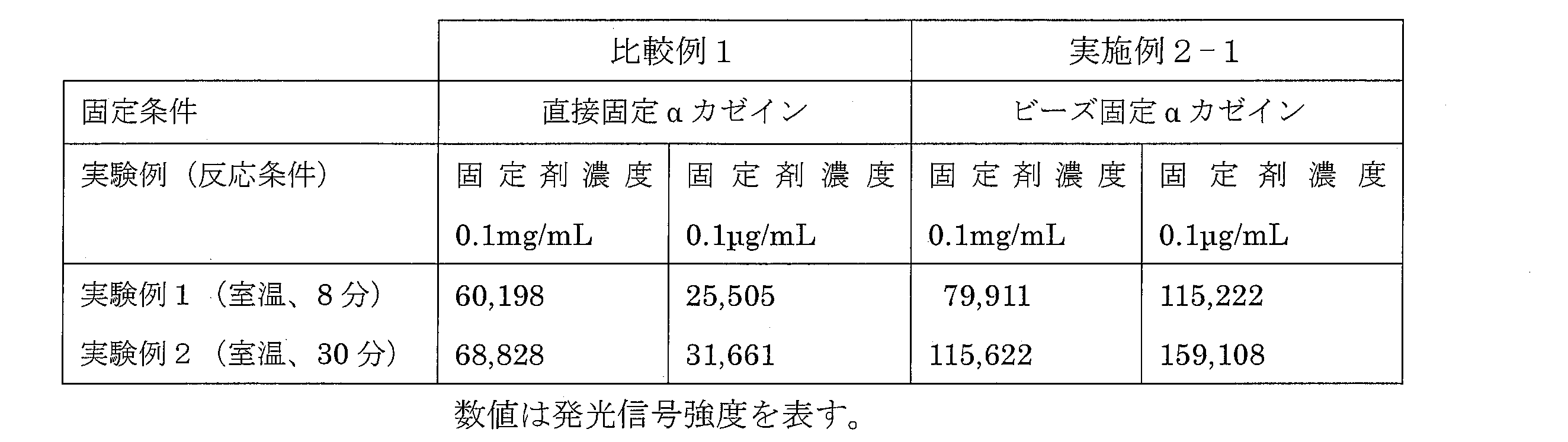
The emission signal intensity obtained from the image of FIG. 4 is shown in Table 1 below.
図4および表1の結果から、固定化剤濃度が低い場合、そもそもタンパク質が固定されない。逆に多すぎると多量のタンパク質が固定され、立体障害により血漿中のIgEとの反応が阻害される。ビーズ担体の直径はμmオーダーであり、タンパク質サイズ3~10nmに比べて大きいので、単位面積当たりの固定化剤量は100分の1以下でよい。ビーズ担体を使用した場合、実効的なタンパク質の固定面積の拡大と固定化剤の削減により、立体障害防止とタンパク質の機能保持効果が相まって信号値の増大となったと考えられる。したがって、図4および表1の結果から、前述の特許文献1等に記載の光固定化法において課題であった低い固定効率を向上させることができた。
4 From the results of FIG. 4 and Table 1, when the concentration of the immobilizing agent is low, the protein is not immobilized in the first place. On the other hand, if the amount is too large, a large amount of protein is immobilized, and the reaction with IgE in plasma is inhibited due to steric hindrance. Since the diameter of the bead carrier is on the order of μm and is larger than the protein size of 3 to 10 nm, the amount of the immobilizing agent per unit area may be 1/100 or less. When the bead carrier is used, it is considered that the signal value is increased due to the combination of the prevention of steric hindrance and the function retaining effect of the protein due to the effective expansion of the protein fixing area and the reduction of the fixing agent. Therefore, from the results of FIG. 4 and Table 1, it was possible to improve the low fixing efficiency, which was a problem in the optical fixing method described in Patent Document 1 and the like described above.
αカゼインの異なる部分ペプチドAおよびB(それぞれ15アミノ酸残基から成る)を直接、あるいはビーズに固定した後、基板に固定し、牛乳アレルギー患者の血漿を反応させた後、アルカリフォスファターゼ標識抗ヒトIgE抗体、ついでアルカリフォスファターゼ基質である発光試薬を反応させて検出した結果を図5に示す。ここでペプチドAは、アミノ酸配列LRFFVAPFPEVFGKEで示す生体物質であり、ペプチドBは、アミノ酸配列KVPQLEIVPNSAEERで示す生体物質である。
Different partial peptides A and B of α-casein (each consisting of 15 amino acid residues) were immobilized directly or on beads, then immobilized on a substrate and reacted with plasma from a milk allergy patient, and then alkaline phosphatase-labeled anti-human IgE. FIG. 5 shows the results of detection by reacting an antibody and then a luminescent reagent which is an alkaline phosphatase substrate. Here, peptide A is a biological material represented by the amino acid sequence LRFFVAFPPEVFFGKE, and peptide B is a biological material represented by the amino acid sequence KVPQLEIVPNSAEEER.
図5の画像から得られた発光信号強度を、下記表2に示す。
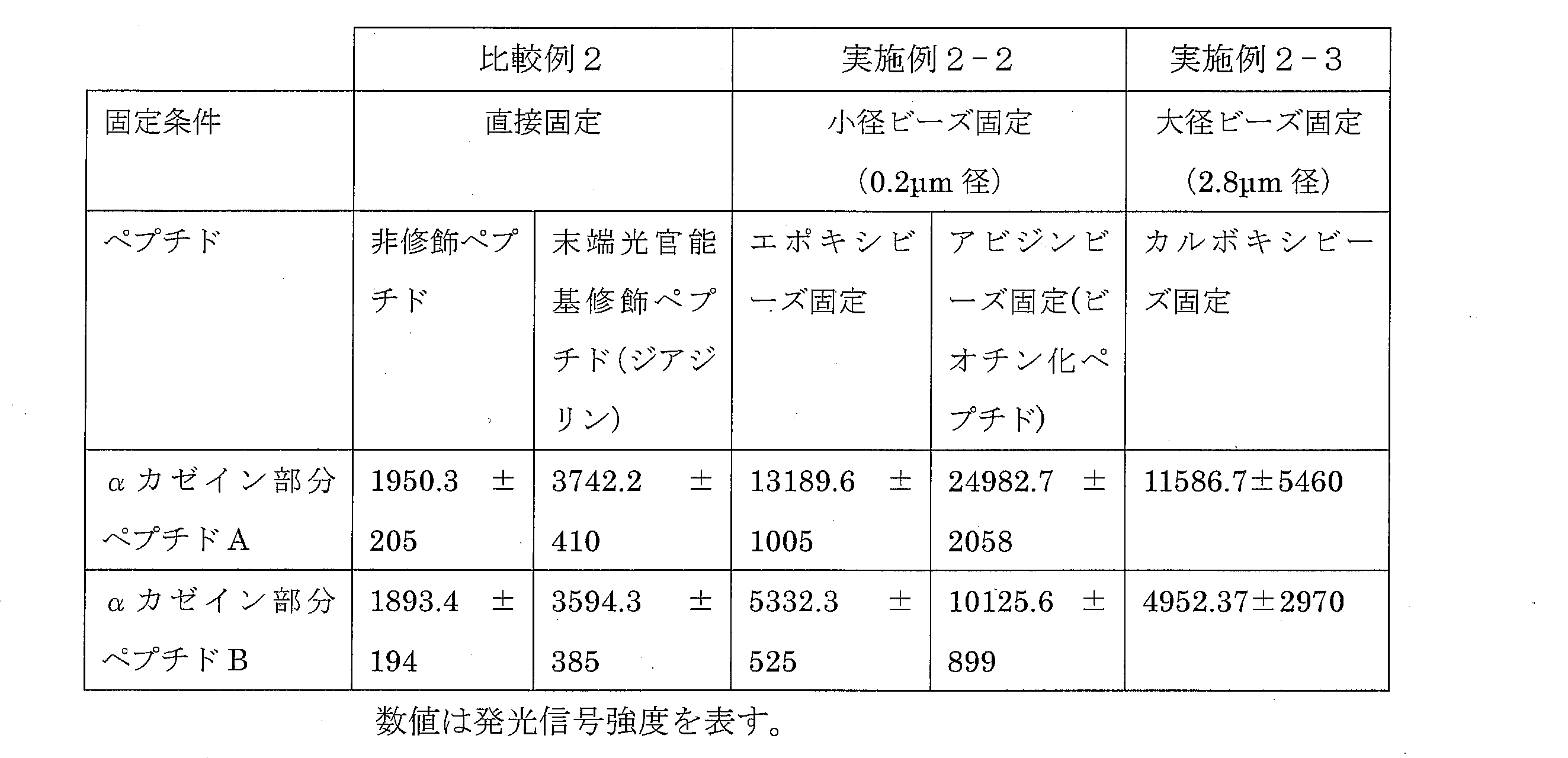
The light emission signal intensity obtained from the image of FIG.
なお、ペプチドA及びBについて、非修飾ペプチド、N末端をジアジリンで光官能基修飾したペプチドおよびN末端ビオチン化ペプチドの合成および精製は、発明者らの仕様に基づき専門の合成会社に依頼した。
For peptides A and B, synthesis and purification of an unmodified peptide, a peptide whose N-terminus was photofunctionally modified with diazirine, and an N-terminal biotinylated peptide were commissioned to a specialized synthesis company based on the specifications of the inventors.
図5および表2の結果からペプチドを固定するに当たり、ビーズ担体を使用した場合のほうが、ビーズ担体を使用しない場合に比べて発光信号強度が3~6倍高いことがわかり、ビーズ担体の優位性を示すことができた。特に、ペプチドを固定する場合は、ビーズ担体を用いなければ実用化できないことを示唆している。したがって、前述の特許文献1等に記載の光固定化法では不可能であったペプチドのような低分子の固定が、ビーズ担体を用いることで可能となった。同時に、次項に述べるように、特定の部位で被固定分子を結合するという課題も解決されている。
From the results shown in FIG. 5 and Table 2, it can be seen that the luminescence signal intensity is 3 to 6 times higher when the bead carrier is used than when the bead carrier is not used. Was able to show. In particular, it suggests that when a peptide is immobilized, it cannot be put into practical use unless a bead carrier is used. Therefore, it is possible to immobilize a low molecule such as a peptide, which was impossible by the photo-immobilization method described in Patent Document 1 described above, by using a bead carrier. At the same time, as described in the next section, the problem of binding an immobilized molecule at a specific site has also been solved.
ビーズ固定については、図5および表2の結果から、非修飾ペプチドをエポキシビーズに固定した場合に比べ、末端ビオチン修飾ペプチドをアビジンビーズに固定した場合には信号値は2倍高い。エポキシビーズでは、ペプチドのN末端だけでなく、ペプチド内に含まれるリシン残基の側鎖アミノ基でも固定されるため、異なる配向のペプチドがビーズ上に存在し、抗体との反応性が低下することが考えられる。アビジンビーズの場合は、アビジン-ビオチンの特異的反応により、N末端のみで固定され、ペプチドの配向が一定となるためと解釈される。したがって、図5および表2の結果から、ペプチドN末端で固定化物質面に固定されていることが保証できないというこれまでの問題が解消されている。
As for bead fixation, from the results of FIG. 5 and Table 2, the signal value is twice as high when the terminal biotin-modified peptide is fixed to the avidin bead, compared to the case where the unmodified peptide is fixed to the epoxy bead. Epoxy beads are fixed not only at the N-terminal of the peptide but also at the side chain amino group of the lysine residue contained in the peptide, so that peptides with different orientations are present on the bead, reducing the reactivity with the antibody. It is possible. In the case of avidin beads, it is interpreted that due to the specific reaction of avidin-biotin, it is fixed only at the N-terminus and the orientation of the peptide becomes constant. Therefore, from the results shown in FIG. 5 and Table 2, the conventional problem that it cannot be guaranteed that the peptide is fixed on the surface of the immobilized substance at the N-terminus is solved.
表2の実施例2-2の場合、スタンプ液中の小径ビーズは沈殿しにくく、ビーズはスポット全体に広がったため、各スポットで大きな発光信号強度が得られ、かつ標準偏差も小さくなったと考えられる。実施例2-3の場合、ビーズ径を大きくしても信号強度が変わらなかったばかりでなく、標準偏差が大きくなった。これは、スタンプ工程中にビーズの沈殿等により、スタンプ液中のビーズ濃度が変化したため、スポット毎に一定でなかったためと考えられる。
In the case of Example 2-2 in Table 2, the small-diameter beads in the stamp solution hardly precipitate, and the beads spread over the entire spot. Therefore, it is considered that a large emission signal intensity was obtained at each spot and the standard deviation was also small. . In Example 2-3, the signal intensity did not change even when the bead diameter was increased, and the standard deviation increased. This is presumably because the bead concentration in the stamp solution changed due to bead precipitation or the like during the stamping process and was not constant for each spot.
タンパク質やペプチドなどを固定したビーズを吐出する別の方法を説明する。図8にその方法を示す。公称100μm径のポリマービーズを用いる。先ず、ビーズを溶液と共に粒径より太いキャピラリに挿入する。キャピラリの先端はY字構造とする。Y字構造の一方は、ビーズより少し太い径のキャピラリとし、ビーズと同じ径の孔が開いた吐出ノズルを設ける。もう一方のY字構造のキャピラリの径は、ビーズよりも小さくする。細径のキャピラリのほうが太径のそれよりもビーズの流速を早くすることができるので、ビーズの径を分別できる。このようにして、所望の径のビーズのみ光架橋剤の上に1個ずつ固定することができる。
Explains another method of discharging beads fixed with protein or peptide. FIG. 8 shows the method. Use nominally 100 μm diameter polymer beads. First, the beads are inserted into the capillary having a larger particle size together with the solution. The tip of the capillary has a Y structure. One of the Y-shaped structures is a capillary having a diameter slightly thicker than the beads, and a discharge nozzle having a hole having the same diameter as the beads is provided. The diameter of the other Y-shaped capillary is made smaller than that of the beads. Since the small capillary can make the flow rate of the beads faster than that of the large diameter, the diameter of the beads can be sorted. In this way, only beads of a desired diameter can be fixed one by one on the photocrosslinking agent.
タンパク質やペプチドなどを固定した磁性ビーズを、磁化力を用いて凝集せずに固定化基体に保持する方法を説明する。図9にその方法を示す。2.8μm径Dynabeads(登録商標)M-270カルボキシ基付を用いる。基体裏面にオン/オフを切り換えられる磁界発生機構を設け、該基体表面には磁性ビーズを保持する保持層を設ける。初めに、基体裏面の磁界をオフの状態で磁性ビーズの分散溶液を基体表面に吐出する。吐出機構のノズル径は、マイクロ流路作製技術を用いて磁性ビーズの直径に合わせているので、磁性ビーズは1個ずつ吐出される。次に、磁界をオンにして液中の磁性ビーズを基体表面に引き付ける。基体に引き付けられた磁性ビーズを該保持層に固定させた後、磁界をオフする。これにより、固定化基体上に磁性ビーズを凝集させずに保持することができる。
A description will be given of a method for holding magnetic beads, on which proteins, peptides, etc. are fixed, on an immobilizing substrate without agglomeration using magnetizing force. FIG. 9 shows the method. 2.8 μm diameter Dynabeads (registered trademark) with M-270 carboxy group is used. A magnetic field generating mechanism that can be switched on / off is provided on the back surface of the substrate, and a holding layer for holding the magnetic beads is provided on the surface of the substrate. First, a dispersion solution of magnetic beads is discharged onto the substrate surface with the magnetic field on the back surface of the substrate turned off. Since the nozzle diameter of the discharge mechanism is adjusted to the diameter of the magnetic beads using the micro-channel manufacturing technique, the magnetic beads are discharged one by one. Next, the magnetic field is turned on and the magnetic beads in the liquid are attracted to the substrate surface. After fixing the magnetic beads attracted to the substrate to the holding layer, the magnetic field is turned off. Thereby, it is possible to hold the magnetic beads on the fixed substrate without aggregating them.
前記の磁界発生機構は、磁化力で磁性ビーズを基体表面上に保持するに足る0.1T(1KG)程度の磁束密度を要する。プリント基板作製技術を応用して、高透磁率の薄膜フェライトコアとこれを囲む薄膜コイルを形成する。これらの構成により、直径1mm以下のコイルの中心にフェライトコアを有する高磁束密度を発生する磁界発生機構が形成される。これをスポットする抗原を格子状に配置する寸法に合わせ、複数個配置する。複数個のコイルには、別に準備する直流電源とオン/オフ制御回路が接続される。磁性ビーズの吐出タイミングに合わせてオン/オフが制御される。
The magnetic field generation mechanism requires a magnetic flux density of about 0.1 T (1 KG) sufficient to hold the magnetic beads on the substrate surface with a magnetizing force. By applying the printed circuit board manufacturing technology, a high permeability thin film ferrite core and a thin film coil surrounding it are formed. With these configurations, a magnetic field generation mechanism that generates a high magnetic flux density having a ferrite core at the center of a coil having a diameter of 1 mm or less is formed. A plurality of antigens to be spotted are arranged in accordance with the dimensions to be arranged in a grid pattern. A DC power supply and an on / off control circuit which are separately prepared are connected to the plurality of coils. On / off is controlled in accordance with the ejection timing of the magnetic beads.
本発明の実施例は、抗体若しくは抗原を固定化した免疫測定用プレートの作製、DNAやRNAを基体上に固定化した核酸チップ、ペプチドやタンパク質を固定化したマイクロアレイ等の作製に好適に用いることができるが、これらに限定されるものではない。
Examples of the present invention are preferably used for the production of immunoassay plates on which antibodies or antigens are immobilized, nucleic acid chips on which DNA or RNA is immobilized on a substrate, microarrays on which peptides or proteins are immobilized, etc. However, it is not limited to these.
なお、前記固定化担体を前記生体物質固定化用基体に保持するための層なしでも、固定化担体(微粒子)に対する光架橋剤の濃度を、保持する層のある場合に比べて10倍程度に増加することにより基体に直接固定することも可能であった。これに対して、前記の形態では、生体物質固定化用基体に保持するための層を使用することで光架橋剤の濃度を1/10程度にすることができる。
Even without a layer for holding the immobilization carrier on the biological substance immobilization substrate, the concentration of the photocrosslinking agent relative to the immobilization carrier (fine particles) is about 10 times that of the case where there is a holding layer. It was also possible to fix directly to the substrate by increasing. On the other hand, in the said form, the density | concentration of a photocrosslinking agent can be made into about 1/10 by using the layer for hold | maintaining to the base | substrate for biological material fixation.
本発明はまた、下記のものを提供する。なお、以下の記載は、前記の発明についての説明に適宜援用し得る。また、前記の記載は、以下の発明についての説明に適宜援用し得る。
The present invention also provides the following. In addition, the following description can be suitably used for the description about the said invention. Moreover, the said description can be suitably used for the description about the following invention.
「生体物質を固定した基体であって、
生体物質である被固定化物質が表面に固定されている複数の粒子、及び、
複数の前記粒子それぞれと前記基体の表面との間に設けられ、複数の前記粒子それぞれを前記基体の表面に固定する固定化剤層
を備えてなる、基体」が提供される。 "A substrate to which biological material is fixed,
A plurality of particles to which an immobilized substance, which is a biological substance, is fixed on the surface; and
There is provided a “substrate” provided with a fixing agent layer provided between each of the plurality of particles and the surface of the substrate, and fixing each of the plurality of particles to the surface of the substrate.
生体物質としては、前記で説明したものが挙げられる。粒子(固定化担体)は、特に限定されないが、一例において、前記で「微粒子」として説明したものが挙げられる。固定化剤層は、粒子を基体の表面に固定するための剤(固定化剤)を含む層である。一例において、固定化剤は、粒子と基体の表面とを架橋する架橋剤である。当該架橋剤は、1分子中に少なくとも2個の光反応性基を有する光架橋剤であることが好ましい。光架橋剤のより具体的な説明は、例えば、前記を参照できる。基体(生体物質固定化用基体)の材質等の説明は、例えば、前記を参照できる。
Examples of biological substances include those described above. The particles (immobilized carrier) are not particularly limited, and examples thereof include those described above as “fine particles”. The immobilizing agent layer is a layer containing an agent (an immobilizing agent) for immobilizing particles on the surface of the substrate. In one example, the immobilizing agent is a cross-linking agent that cross-links the particles and the surface of the substrate. The crosslinking agent is preferably a photocrosslinking agent having at least two photoreactive groups in one molecule. For more specific description of the photocrosslinking agent, reference can be made to the above, for example. For the description of the material and the like of the substrate (substrate for immobilizing biological material), the above can be referred to, for example.
基体の前記表面において、前記固定化剤層は複数のスポットとして配置されていてもよい。1つのスポットには、複数個の前記粒子が固定されていてもよいし、1個のみが固定されていてもよい。一例において、0.2μm径のビーズで多数個(数万個以上)固定することにより、スポット間の均一性および再現性が向上する。
The fixing agent layer may be arranged as a plurality of spots on the surface of the substrate. A plurality of particles may be fixed to one spot, or only one particle may be fixed. In one example, by fixing a large number (tens of thousands or more) of beads having a diameter of 0.2 μm, uniformity between spots and reproducibility are improved.
互いに異なる生体物質が固定されている複数の前記粒子が、互いに異なる前記スポットに配置されていてもよい。具体例は、実施例2および図7の(2)を参照できる。
A plurality of the particles to which different biological substances are fixed may be arranged in the different spots. For a specific example, reference can be made to Example 2 and (2) of FIG.
基体の前記表面は平滑であることが好ましい。
The surface of the substrate is preferably smooth.
基体の前記表面は、前記生体物質と相互作用する物質との非特異的吸着が抑制された表面であることが好ましい。非特異的吸着の抑制の形態は上述のとおりである。
The surface of the substrate is preferably a surface in which non-specific adsorption with a substance that interacts with the biological substance is suppressed. The form of suppression of nonspecific adsorption is as described above.
前記粒子は、有機微粒子、無機微粒子、または磁性微粒子であり得る。
The particles may be organic fine particles, inorganic fine particles, or magnetic fine particles.
前記生体物質は、タンパク質またはペプチドであってもよい。また、前記ペプチドは、そのC末端またはN末端において、前記粒子に固定されていることが好ましい。
The biological substance may be a protein or a peptide. The peptide is preferably fixed to the particle at the C-terminal or N-terminal.
前記生体物質は一例において、アレルゲンである。
In one example, the biological substance is an allergen.
「生体物質との相互作用の評価方法であって、
前記基体に対してアプライされた被験物質と、前記基体に固定された前記生体物質との相互作用を評価する工程を含む、方法」が提供される。 “A method for evaluating interactions with biological materials,
There is provided a method comprising the step of evaluating the interaction between a test substance applied to the substrate and the biological substance immobilized on the substrate.
前記評価方法の一例において、被験物質は血液(全血、血清、血漿いずれも可)であり、生体物質はアレルゲンである。この評価方法によって、被験物質と生体物質(アレルゲン)との有意な相互作用が検出されれば、被験物質中にアレルゲンに対する抗体が含まれているということになる。すなわち、被験物質を採取したヒト又は動物が、アレルゲンに対するアレルギーを有し得る指標となる。
In one example of the evaluation method, the test substance is blood (whole blood, serum, or plasma is acceptable), and the biological substance is allergen. If a significant interaction between the test substance and the biological substance (allergen) is detected by this evaluation method, it means that the test substance contains an antibody against the allergen. That is, it is an indicator that the human or animal from which the test substance is collected can have allergies to the allergen.
「生体物質である被固定化物質が表面に固定されている複数の固定化担体を、固定化剤層を介して、基体の表面にスポット状に固定する工程を含む、生体物質の固定化方法」が提供される。固定化担体の形状は特に限定されないが、例えば、粒子状である。
“A method for immobilizing a biological substance, comprising a step of fixing a plurality of immobilization carriers on which a substance to be immobilized, which is a biological substance, is immobilized on a surface, to a surface of a substrate in a spot shape via an immobilizing agent layer Is provided. The shape of the immobilization carrier is not particularly limited, but is, for example, a particulate shape.
前記固定化担体は、有機微粒子、無機微粒子、または磁性微粒子であり得る。
The immobilization carrier may be organic fine particles, inorganic fine particles, or magnetic fine particles.
一例において、前記固定化剤層は、前記固定化担体と基体の前記表面とを架橋する架橋剤を含んでいる。また、前記架橋剤は、1分子中に少なくとも2個の光反応性基を有する光架橋剤であることが好ましい。
In one example, the immobilizing agent layer contains a cross-linking agent that cross-links the immobilization carrier and the surface of the substrate. The crosslinking agent is preferably a photocrosslinking agent having at least two photoreactive groups in one molecule.
一例において、複数の前記固定化担体を基体の表面にスポット状に固定をする前記工程は、
1)複数の前記固定化担体と前記固定化剤とを含む液体を、基体の前記表面にスポット状にアプライすること、または、2)前記固定化剤を、基体の前記表面にスポット状にアプライした後に、複数の前記固定化担体を基体の前記表面にアプライすること、を含んでいる。 In one example, the step of fixing a plurality of the immobilization carriers on the surface of the substrate in the form of spots,
1) A liquid containing a plurality of the immobilization carriers and the immobilizing agent is applied to the surface of the substrate in a spot shape, or 2) the immobilizing agent is applied to the surface of the substrate in a spot shape. And then applying a plurality of the immobilization carriers to the surface of the substrate.
一例において、前記2)において、前記固定化担体は、基体の前記表面にアプライされた前記固定化剤のスポットに対して選択的にアプライされる。
In one example, in 2), the immobilization carrier is selectively applied to the spot of the immobilizing agent applied to the surface of the substrate.
「前記基体の製造方法であって、
複数の前記粒子を、前記固定化剤層を介して、前記基体の表面に固定する工程を含む、製造方法」が提供される。 “A method for producing the substrate,
There is provided a “manufacturing method” including a step of fixing a plurality of the particles to the surface of the substrate via the fixing agent layer.
複数の前記粒子を、前記固定化剤層を介して、前記基体の表面に固定する工程を含む、製造方法」が提供される。 “A method for producing the substrate,
There is provided a “manufacturing method” including a step of fixing a plurality of the particles to the surface of the substrate via the fixing agent layer.
一例において、複数の前記粒子を、基体の表面に固定をする前記工程は、
1)複数の前記粒子と前記固定化剤とを含む液体を、基体の前記表面にスポット状にアプライすること、または、2)前記固定化剤を、基体の前記表面にスポット状にアプライした後に、複数の前記粒子を基体の前記表面にアプライすること、を含んでいる。 In one example, the step of fixing a plurality of the particles to the surface of the substrate includes:
1) A liquid containing a plurality of the particles and the immobilizing agent is applied to the surface of the substrate in a spot shape, or 2) the immobilizing agent is applied to the surface of the substrate in a spot shape. Applying a plurality of the particles to the surface of the substrate.
一例において、前記2)において、前記粒子は、基体の前記表面にアプライされた前記固定化剤のスポットに対して選択的にアプライされる。
In one example, in 2), the particles are selectively applied to the spots of the immobilizing agent applied to the surface of the substrate.
本発明は上述した各実施形態に限定されるものではなく、請求項に示した範囲で種々の変更が可能であり、異なる実施形態にそれぞれ開示された技術的手段を適宜組み合わせて得られる実施形態についても本発明の技術的範囲に含まれる。さらに、各実施形態にそれぞれ開示された技術的手段を組み合わせることにより、新しい技術的特徴を形成することができる。
The present invention is not limited to the above-described embodiments, and various modifications are possible within the scope shown in the claims, and embodiments obtained by appropriately combining technical means disclosed in different embodiments. Is also included in the technical scope of the present invention. Furthermore, a new technical feature can be formed by combining the technical means disclosed in each embodiment.
本発明によれば、固定化すべき物質を配列や配向をそろえて固定化することができ、非特異的吸着が抑止された安定な固定化基体を得ることができる。これにより、例えば、種類の異なるタンパク質やペプチドを複数個のスポットとして固定した検査基体を作製し、多項目の同時計測が可能となり、高精度かつ高信頼性の診断システムが実現できる。
According to the present invention, substances to be immobilized can be immobilized with the same arrangement and orientation, and a stable immobilized substrate in which nonspecific adsorption is suppressed can be obtained. Thereby, for example, a test substrate in which different types of proteins and peptides are fixed as a plurality of spots can be produced, and multiple items can be measured simultaneously, and a highly accurate and reliable diagnostic system can be realized.
Claims (28)
- 生体物質からなる被固定化物質を固定化するために生体物質に応じた表面修飾を有する固定化担体を用い、前記固定化担体表面に前記被固定化物質を予め固定しておき、前記固定化担体を生体物質固定化用基体に保持するための層を設け、当該層の上に前記固定化担体をスポット状にスタンプすることを特徴とする生体物質固定化方法。 In order to immobilize an immobilization substance made of a biological material, an immobilization carrier having a surface modification corresponding to the biological material is used, the immobilization substance is immobilized in advance on the surface of the immobilization carrier, and the immobilization is performed. A biological material immobilization method comprising: providing a layer for holding a carrier on a biological material immobilization substrate; and stamping the immobilization carrier on the layer in a spot shape.
- 複数の前記固定化担体に互いに異なる生体物質を予め固定しておき、前記層の上の互いに異なる位置に当該複数の固定化担体をスポット状にスタンプすることを特徴とする請求項1に記載の生体物質固定化方法。 The biological material different from each other is fixed in advance on the plurality of immobilization carriers, and the plurality of immobilization carriers are stamped in spots at different positions on the layer. Biological substance immobilization method.
- 前記固定化担体として、有機微粒子または無機微粒子、あるいは磁性微粒子を用いることを特徴とする請求項1または2に記載の生体物質固定化方法。 3. The biological material immobilization method according to claim 1 or 2, wherein organic fine particles, inorganic fine particles, or magnetic fine particles are used as the immobilization carrier.
- 前記固定化担体を生体物質固定化用基体に固定化する方法として、1分子中に少なくとも2個の光反応基を有する光架橋剤を用いることを特徴とする請求項1~3の何れか一項に記載の生体物質固定化方法。 The photocrosslinking agent having at least two photoreactive groups in one molecule is used as a method for immobilizing the immobilization carrier on the biological material immobilization substrate. The biological material immobilization method according to Item.
- 前記固定化担体を前記生体物質固定化用基体に保持するための層の上に、当該層と前記固定化担体とを架橋する架橋剤及び前記固定化担体をスポット状にスタンプする方法として、前記架橋剤と前記固定化担体を混合した混合液をスタンプする混合スタンプ法、または、先ず前記架橋剤をスタンプし、次に前記固定化担体をスタンプする分離スタンプ法、を採用することを特徴とする請求項1~4の何れか一項に記載の生体物質固定化方法。 On the layer for holding the immobilization carrier on the biological substance immobilization substrate, as a method of stamping the immobilization carrier and the cross-linking agent that cross-links the layer and the immobilization carrier in a spot shape, A mixed stamp method in which a mixed solution in which a crosslinking agent and the immobilization carrier are mixed is stamped, or a separation stamp method in which the crosslinking agent is first stamped and then the immobilization carrier is stamped is employed. The biological material immobilization method according to any one of claims 1 to 4.
- 前記固定化担体を前記生体物質固定化用基体に保持するための層として、水溶性ポリマーを塗布したことを特徴とする請求項1~5の何れか一項に記載の生体物質固定化方法。 The biological material immobilization method according to any one of claims 1 to 5, wherein a water-soluble polymer is applied as a layer for holding the immobilization carrier on the biological material immobilization substrate.
- 生体物質を固定した基体であって、
生体物質である被固定化物質が表面に固定されている複数の粒子、及び、
複数の前記粒子それぞれと前記基体の表面との間に設けられ、複数の前記粒子それぞれを前記基体の表面に固定する固定化剤層
を備えてなる、基体。 A substrate on which a biological substance is fixed,
A plurality of particles to which an immobilized substance, which is a biological substance, is fixed on the surface; and
A substrate comprising a fixing agent layer provided between each of the plurality of particles and the surface of the substrate and fixing each of the plurality of particles to the surface of the substrate. - 前記固定化剤層は、前記粒子と基体の前記表面とを架橋する架橋剤を含んでいる、請求項7に記載の基体。 The substrate according to claim 7, wherein the fixing agent layer includes a crosslinking agent that crosslinks the particles and the surface of the substrate.
- 前記架橋剤は、1分子中に少なくとも2個の光反応性基を有する光架橋剤である、請求項8に記載の基体。 The substrate according to claim 8, wherein the crosslinking agent is a photocrosslinking agent having at least two photoreactive groups in one molecule.
- 基体の前記表面において、前記固定化剤層は複数のスポットとして配置されている、請求項7~9の何れか一項に記載の基体。 10. The substrate according to claim 7, wherein the fixing agent layer is arranged as a plurality of spots on the surface of the substrate.
- 互いに異なる生体物質が固定されている複数の前記粒子が、互いに異なる前記スポットに配置されている、請求項10に記載の基体。 11. The substrate according to claim 10, wherein a plurality of the particles to which different biological substances are fixed are arranged in the different spots.
- 基体の前記表面は平滑である、請求項7~11の何れか一項に記載の基体。 The substrate according to any one of claims 7 to 11, wherein the surface of the substrate is smooth.
- 基体の前記表面は、前記生体物質と相互作用する物質との非特異的吸着が抑制された表面である、請求項7~12の何れか一項に記載の基体。 The substrate according to any one of claims 7 to 12, wherein the surface of the substrate is a surface in which non-specific adsorption with a substance that interacts with the biological substance is suppressed.
- 前記粒子は、有機微粒子、無機微粒子、または磁性微粒子である、請求項7~13の何れか一項に記載の基体。 The substrate according to any one of claims 7 to 13, wherein the particles are organic fine particles, inorganic fine particles, or magnetic fine particles.
- 前記生体物質は、タンパク質またはペプチドである、請求項7~14の何れか一項に記載の基体。 The substrate according to any one of claims 7 to 14, wherein the biological substance is a protein or a peptide.
- 前記ペプチドは、そのC末端またはN末端において、前記粒子に固定されている、請求項15に記載の基体。 The substrate according to claim 15, wherein the peptide is fixed to the particle at its C-terminal or N-terminal.
- 前記生体物質はアレルゲンである、請求項7~16の何れか一項に記載の基体。 The substrate according to any one of claims 7 to 16, wherein the biological substance is an allergen.
- 生体物質との相互作用の評価方法であって、
請求項7~17の何れか一項に記載の基体に対してアプライされた被験物質と、当該基体に固定された前記生体物質との相互作用を評価する工程を含む、方法。 A method for evaluating an interaction with a biological material,
A method comprising evaluating an interaction between a test substance applied to the substrate according to any one of claims 7 to 17 and the biological substance fixed to the substrate. - 前記被験物質は血液であり、前記生体物質はアレルゲンである、請求項18に記載の方法。 The method according to claim 18, wherein the test substance is blood and the biological substance is an allergen.
- 生体物質である被固定化物質が表面に固定されている複数の固定化担体を、固定化剤層を介して、基体の表面にスポット状に固定する工程を含む、生体物質の固定化方法。 A method for immobilizing a biological material, comprising a step of fixing a plurality of immobilization carriers on which a substance to be immobilized, which is a biological material, is immobilized on a surface, in a spot shape via an immobilizing agent layer.
- 前記固定化担体は、有機微粒子、無機微粒子、または磁性微粒子である、請求項20に記載の方法。 The method according to claim 20, wherein the immobilization carrier is organic fine particles, inorganic fine particles, or magnetic fine particles.
- 前記固定化剤層は、前記固定化担体と基体の前記表面とを架橋する架橋剤を含んでいる、請求項20または21に記載の方法。 The method according to claim 20 or 21, wherein the immobilizing agent layer contains a cross-linking agent that cross-links the immobilization carrier and the surface of the substrate.
- 前記架橋剤は、1分子中に少なくとも2個の光反応性基を有する光架橋剤である、請求項22に記載の方法。 The method according to claim 22, wherein the crosslinking agent is a photocrosslinking agent having at least two photoreactive groups in one molecule.
- 複数の前記固定化担体を基体の表面にスポット状に固定をする前記工程は、
1)複数の前記固定化担体と前記固定化剤とを含む液体を、基体の前記表面にスポット状にアプライすること、または、2)前記固定化剤を、基体の前記表面にスポット状にアプライした後に、複数の前記固定化担体を基体の前記表面にアプライすること、を含んでいる、請求項20~23の何れか一項に記載の方法。 The step of fixing a plurality of the immobilization carriers on the surface of the substrate in the form of spots,
1) A liquid containing a plurality of the immobilization carriers and the immobilizing agent is applied to the surface of the substrate in a spot shape, or 2) the immobilizing agent is applied to the surface of the substrate in a spot shape. The method according to any one of claims 20 to 23, further comprising: applying a plurality of the immobilization carriers to the surface of the substrate. - 前記2)において、前記固定化担体は、基体の前記表面にアプライされた前記固定化剤のスポットに対して選択的にアプライされる、請求項24に記載の方法。 25. The method according to claim 24, wherein, in 2), the immobilization carrier is selectively applied to the spot of the immobilizing agent applied to the surface of a substrate.
- 請求項7~17の何れか一項に記載の基体の製造方法であって、
複数の前記粒子を、前記固定化剤層を介して、前記基体の表面に固定する工程を含む、製造方法。 A method for producing a substrate according to any one of claims 7 to 17,
The manufacturing method including the process of fix | immobilizing the said several particle | grain to the surface of the said base | substrate via the said fixing agent layer. - 複数の前記粒子を、基体の表面に固定をする前記工程は、
1)複数の前記粒子と前記固定化剤とを含む液体を、基体の前記表面にスポット状にアプライすること、または、2)前記固定化剤を、基体の前記表面にスポット状にアプライした後に、複数の前記粒子を基体の前記表面にアプライすること、を含んでいる、請求項26に記載の方法。 The step of fixing the plurality of particles to the surface of the substrate includes:
1) A liquid containing a plurality of the particles and the immobilizing agent is applied to the surface of the substrate in a spot shape, or 2) the immobilizing agent is applied to the surface of the substrate in a spot shape. 27. The method of claim 26, comprising applying a plurality of the particles to the surface of a substrate. - 前記2)において、前記粒子は、基体の前記表面にアプライされた前記固定化剤のスポットに対して選択的にアプライされる、請求項27に記載の方法。 28. The method of claim 27, wherein in 2), the particles are selectively applied to spots of the immobilizing agent applied to the surface of a substrate.
Priority Applications (4)
| Application Number | Priority Date | Filing Date | Title |
|---|---|---|---|
| PCT/JP2017/031281 WO2018154814A1 (en) | 2017-02-24 | 2017-08-30 | Biomaterial immobilizing method and uses thereof |
| US16/487,670 US20200025754A1 (en) | 2017-02-24 | 2017-08-30 | Biomaterial immobilizing method and uses thereof |
| CN201780087192.6A CN110325858B (en) | 2017-02-24 | 2017-08-30 | Method for immobilizing biological material and use thereof |
| EP17897766.6A EP3588087A4 (en) | 2017-02-24 | 2017-08-30 | Biomaterial immobilizing method and uses thereof |
Applications Claiming Priority (3)
| Application Number | Priority Date | Filing Date | Title |
|---|---|---|---|
| JP2017-033646 | 2017-02-24 | ||
| JP2017033646A JP7130919B2 (en) | 2016-03-11 | 2017-02-24 | Biological material immobilization method |
| PCT/JP2017/031281 WO2018154814A1 (en) | 2017-02-24 | 2017-08-30 | Biomaterial immobilizing method and uses thereof |
Publications (1)
| Publication Number | Publication Date |
|---|---|
| WO2018154814A1 true WO2018154814A1 (en) | 2018-08-30 |
Family
ID=63255464
Family Applications (1)
| Application Number | Title | Priority Date | Filing Date |
|---|---|---|---|
| PCT/JP2017/031281 WO2018154814A1 (en) | 2017-02-24 | 2017-08-30 | Biomaterial immobilizing method and uses thereof |
Country Status (5)
| Country | Link |
|---|---|
| US (1) | US20200025754A1 (en) |
| EP (1) | EP3588087A4 (en) |
| JP (1) | JP7130919B2 (en) |
| CN (1) | CN110325858B (en) |
| WO (1) | WO2018154814A1 (en) |
Cited By (3)
| Publication number | Priority date | Publication date | Assignee | Title |
|---|---|---|---|---|
| WO2022050418A1 (en) | 2020-09-07 | 2022-03-10 | 三菱瓦斯化学株式会社 | Biochip, method for producing same, and use of same |
| WO2022050416A1 (en) | 2020-09-07 | 2022-03-10 | 三菱瓦斯化学株式会社 | Allergic disease determination method and determination system |
| WO2023027183A1 (en) * | 2021-08-27 | 2023-03-02 | 国立大学法人神戸大学 | Technique for aligning particles on substrate without agglomeration |
Citations (10)
| Publication number | Priority date | Publication date | Assignee | Title |
|---|---|---|---|---|
| JP2003515133A (en) * | 1999-11-18 | 2003-04-22 | スリーエム イノベイティブ プロパティズ カンパニー | Film-based addressable programmable electronic matrix article and method of making and using same |
| JP2005505762A (en) * | 2001-10-05 | 2005-02-24 | サーモディックス,インコーポレイティド | Arrays with clustered sequences and methods of making and using |
| JP2005506527A (en) * | 2001-10-05 | 2005-03-03 | サーモディックス,インコーポレイティド | Randomly arranged array group, and method for producing and using the same |
| WO2005111618A1 (en) | 2004-05-18 | 2005-11-24 | Riken | Substance-fixing agents, method of fixing substance with the same, and substrate having substance fixed with the same |
| JP2007139587A (en) * | 2005-11-18 | 2007-06-07 | Institute Of Physical & Chemical Research | Substance fixing agent, substance fixing method and substance fixing substrate |
| JP2007516442A (en) * | 2003-12-16 | 2007-06-21 | コーニンクレッカ フィリップス エレクトロニクス エヌ ヴィ | Molecular stamp for printing biomolecules on a substrate |
| JP2010101661A (en) | 2008-10-21 | 2010-05-06 | Girasol Bio Kk | Method for immobilizing substance |
| JP2011247618A (en) * | 2010-05-24 | 2011-12-08 | Girasol Bio Kk | Allergy diagnosis kit |
| JP2013536440A (en) * | 2010-08-20 | 2013-09-19 | ザ リージェンツ オブ ザ ユニバーシティ オブ カリフォルニア | Small molecule arrays and methods of using and making them |
| WO2014007034A1 (en) | 2012-07-06 | 2014-01-09 | 株式会社 日立ハイテクノロジーズ | Analysis device and analysis method |
Family Cites Families (4)
| Publication number | Priority date | Publication date | Assignee | Title |
|---|---|---|---|---|
| JP2005147718A (en) * | 2003-11-11 | 2005-06-09 | Tokyoto Igaku Kenkyu Kiko | Microbeads array production method |
| JP4505581B2 (en) * | 2005-05-17 | 2010-07-21 | 独立行政法人理化学研究所 | Substance immobilization method |
| US20120202709A1 (en) * | 2011-02-09 | 2012-08-09 | Adeptrix Corp. | Devices and Methods for Producing and Analyzing Microarrays |
| US10195313B2 (en) * | 2014-04-10 | 2019-02-05 | Wisconsin Alumni Research Foundation | Method for forming hydrogel arrays using surfaces with differential wettability |
-
2017
- 2017-02-24 JP JP2017033646A patent/JP7130919B2/en active Active
- 2017-08-30 CN CN201780087192.6A patent/CN110325858B/en active Active
- 2017-08-30 US US16/487,670 patent/US20200025754A1/en active Pending
- 2017-08-30 WO PCT/JP2017/031281 patent/WO2018154814A1/en unknown
- 2017-08-30 EP EP17897766.6A patent/EP3588087A4/en active Pending
Patent Citations (10)
| Publication number | Priority date | Publication date | Assignee | Title |
|---|---|---|---|---|
| JP2003515133A (en) * | 1999-11-18 | 2003-04-22 | スリーエム イノベイティブ プロパティズ カンパニー | Film-based addressable programmable electronic matrix article and method of making and using same |
| JP2005505762A (en) * | 2001-10-05 | 2005-02-24 | サーモディックス,インコーポレイティド | Arrays with clustered sequences and methods of making and using |
| JP2005506527A (en) * | 2001-10-05 | 2005-03-03 | サーモディックス,インコーポレイティド | Randomly arranged array group, and method for producing and using the same |
| JP2007516442A (en) * | 2003-12-16 | 2007-06-21 | コーニンクレッカ フィリップス エレクトロニクス エヌ ヴィ | Molecular stamp for printing biomolecules on a substrate |
| WO2005111618A1 (en) | 2004-05-18 | 2005-11-24 | Riken | Substance-fixing agents, method of fixing substance with the same, and substrate having substance fixed with the same |
| JP2007139587A (en) * | 2005-11-18 | 2007-06-07 | Institute Of Physical & Chemical Research | Substance fixing agent, substance fixing method and substance fixing substrate |
| JP2010101661A (en) | 2008-10-21 | 2010-05-06 | Girasol Bio Kk | Method for immobilizing substance |
| JP2011247618A (en) * | 2010-05-24 | 2011-12-08 | Girasol Bio Kk | Allergy diagnosis kit |
| JP2013536440A (en) * | 2010-08-20 | 2013-09-19 | ザ リージェンツ オブ ザ ユニバーシティ オブ カリフォルニア | Small molecule arrays and methods of using and making them |
| WO2014007034A1 (en) | 2012-07-06 | 2014-01-09 | 株式会社 日立ハイテクノロジーズ | Analysis device and analysis method |
Non-Patent Citations (3)
| Title |
|---|
| See also references of EP3588087A4 |
| TINASHE B RUWONARYAN MCBRIDEREBECCA CHAPPELSTEVEN R HEADPHILLIP ORDOUKHANIANDENNIS R. BURTONMANSUN LAW: "Optimization of peptide arrays for studying antibodies to hepatitis C virus continuous epitopes", J IMMUNOL METHODS, vol. 15, 2014, pages 35 - 42 |
| VICTOR ET MANCILLARUDOLF VOLKMER: "Peptide arrays on planar supports", METHODS IN MOLECULAR BIOLOGY, vol. 1352, 2015, pages 3 - 17 |
Cited By (4)
| Publication number | Priority date | Publication date | Assignee | Title |
|---|---|---|---|---|
| WO2022050418A1 (en) | 2020-09-07 | 2022-03-10 | 三菱瓦斯化学株式会社 | Biochip, method for producing same, and use of same |
| WO2022050416A1 (en) | 2020-09-07 | 2022-03-10 | 三菱瓦斯化学株式会社 | Allergic disease determination method and determination system |
| WO2023027183A1 (en) * | 2021-08-27 | 2023-03-02 | 国立大学法人神戸大学 | Technique for aligning particles on substrate without agglomeration |
| JP7334003B2 (en) | 2021-08-27 | 2023-08-28 | 国立大学法人神戸大学 | Technology for arranging particles on a substrate without agglomeration |
Also Published As
| Publication number | Publication date |
|---|---|
| EP3588087A4 (en) | 2020-12-23 |
| US20200025754A1 (en) | 2020-01-23 |
| EP3588087A1 (en) | 2020-01-01 |
| JP7130919B2 (en) | 2022-09-06 |
| JP2017167129A (en) | 2017-09-21 |
| CN110325858A (en) | 2019-10-11 |
| CN110325858B (en) | 2023-07-21 |
Similar Documents
| Publication | Publication Date | Title |
|---|---|---|
| EP1813946B1 (en) | Biomaterial structure, method of producing the same and uses thereof | |
| AU713388B2 (en) | Device and apparatus for the simultaneous detection of multiple analytes | |
| JP2022521672A (en) | Single molecule quantitative detection method and detection system | |
| US20080044830A1 (en) | Three-Dimensional Nanostructured and Microstructured Supports | |
| EP0874242A1 (en) | Device and apparatus for the simultaneous detection of multiple analytes | |
| JP2009545739A (en) | Method for determining analyte concentration using analyte sensor molecules bound to a porous membrane | |
| WO2018154814A1 (en) | Biomaterial immobilizing method and uses thereof | |
| JP2005501238A (en) | Particles modified with affinity tags | |
| US20180120310A1 (en) | Method of and System for Printing In-Well Calibration Features | |
| JP4434971B2 (en) | Microparticles for capture beads and capture beads and biochips using the same | |
| JP5148818B2 (en) | New solid support and use thereof | |
| JP2013543981A5 (en) | ||
| JP4197279B2 (en) | Biologically-derived substance detection substrate and manufacturing method thereof | |
| JP2007285835A (en) | Plate for bioplate, manufacturing method therefor and the bioplate | |
| US20050191644A1 (en) | Methods for detecting biopolymers; biochips; methods for immobilizing antibodies; and substrates to which antibodies are immobilized | |
| JP4230126B2 (en) | Biological material chip | |
| JP2005030913A (en) | Biochip | |
| JP4353091B2 (en) | Protein and peptide detection method | |
| JP4353073B2 (en) | Biochip and manufacturing method thereof | |
| JP2008076093A (en) | Manufacturing method of analyzer, and coating composition | |
| JP2006132943A (en) | Method of manufacturing biochip | |
| She | Surface functionalisation of encoded SU-8 microparticles and their uses in multiplexed suspension biological assays |
Legal Events
| Date | Code | Title | Description |
|---|---|---|---|
| 121 | Ep: the epo has been informed by wipo that ep was designated in this application |
Ref document number: 17897766 Country of ref document: EP Kind code of ref document: A1 |
|
| NENP | Non-entry into the national phase |
Ref country code: DE |
|
| ENP | Entry into the national phase |
Ref document number: 2017897766 Country of ref document: EP Effective date: 20190924 |
|
| NENP | Non-entry into the national phase |
Ref country code: JP |