WO2018151251A1 - 軸流回転機械、動翼部材 - Google Patents
軸流回転機械、動翼部材 Download PDFInfo
- Publication number
- WO2018151251A1 WO2018151251A1 PCT/JP2018/005476 JP2018005476W WO2018151251A1 WO 2018151251 A1 WO2018151251 A1 WO 2018151251A1 JP 2018005476 W JP2018005476 W JP 2018005476W WO 2018151251 A1 WO2018151251 A1 WO 2018151251A1
- Authority
- WO
- WIPO (PCT)
- Prior art keywords
- central axis
- axis direction
- platform
- shroud
- stationary blade
- Prior art date
Links
Images


Classifications
-
- F—MECHANICAL ENGINEERING; LIGHTING; HEATING; WEAPONS; BLASTING
- F01—MACHINES OR ENGINES IN GENERAL; ENGINE PLANTS IN GENERAL; STEAM ENGINES
- F01D—NON-POSITIVE DISPLACEMENT MACHINES OR ENGINES, e.g. STEAM TURBINES
- F01D9/00—Stators
- F01D9/02—Nozzles; Nozzle boxes; Stator blades; Guide conduits, e.g. individual nozzles
- F01D9/04—Nozzles; Nozzle boxes; Stator blades; Guide conduits, e.g. individual nozzles forming ring or sector
-
- F—MECHANICAL ENGINEERING; LIGHTING; HEATING; WEAPONS; BLASTING
- F01—MACHINES OR ENGINES IN GENERAL; ENGINE PLANTS IN GENERAL; STEAM ENGINES
- F01D—NON-POSITIVE DISPLACEMENT MACHINES OR ENGINES, e.g. STEAM TURBINES
- F01D1/00—Non-positive-displacement machines or engines, e.g. steam turbines
- F01D1/02—Non-positive-displacement machines or engines, e.g. steam turbines with stationary working-fluid guiding means and bladed or like rotor, e.g. multi-bladed impulse steam turbines
- F01D1/04—Non-positive-displacement machines or engines, e.g. steam turbines with stationary working-fluid guiding means and bladed or like rotor, e.g. multi-bladed impulse steam turbines traversed by the working-fluid substantially axially
-
- F—MECHANICAL ENGINEERING; LIGHTING; HEATING; WEAPONS; BLASTING
- F01—MACHINES OR ENGINES IN GENERAL; ENGINE PLANTS IN GENERAL; STEAM ENGINES
- F01D—NON-POSITIVE DISPLACEMENT MACHINES OR ENGINES, e.g. STEAM TURBINES
- F01D1/00—Non-positive-displacement machines or engines, e.g. steam turbines
- F01D1/18—Non-positive-displacement machines or engines, e.g. steam turbines without stationary working-fluid guiding means
- F01D1/20—Non-positive-displacement machines or engines, e.g. steam turbines without stationary working-fluid guiding means traversed by the working-fluid substantially axially
-
- F—MECHANICAL ENGINEERING; LIGHTING; HEATING; WEAPONS; BLASTING
- F01—MACHINES OR ENGINES IN GENERAL; ENGINE PLANTS IN GENERAL; STEAM ENGINES
- F01D—NON-POSITIVE DISPLACEMENT MACHINES OR ENGINES, e.g. STEAM TURBINES
- F01D11/00—Preventing or minimising internal leakage of working-fluid, e.g. between stages
- F01D11/001—Preventing or minimising internal leakage of working-fluid, e.g. between stages for sealing space between stator blade and rotor
-
- F—MECHANICAL ENGINEERING; LIGHTING; HEATING; WEAPONS; BLASTING
- F01—MACHINES OR ENGINES IN GENERAL; ENGINE PLANTS IN GENERAL; STEAM ENGINES
- F01D—NON-POSITIVE DISPLACEMENT MACHINES OR ENGINES, e.g. STEAM TURBINES
- F01D11/00—Preventing or minimising internal leakage of working-fluid, e.g. between stages
- F01D11/02—Preventing or minimising internal leakage of working-fluid, e.g. between stages by non-contact sealings, e.g. of labyrinth type
-
- F—MECHANICAL ENGINEERING; LIGHTING; HEATING; WEAPONS; BLASTING
- F01—MACHINES OR ENGINES IN GENERAL; ENGINE PLANTS IN GENERAL; STEAM ENGINES
- F01D—NON-POSITIVE DISPLACEMENT MACHINES OR ENGINES, e.g. STEAM TURBINES
- F01D5/00—Blades; Blade-carrying members; Heating, heat-insulating, cooling or antivibration means on the blades or the members
- F01D5/12—Blades
- F01D5/14—Form or construction
- F01D5/20—Specially-shaped blade tips to seal space between tips and stator
-
- F—MECHANICAL ENGINEERING; LIGHTING; HEATING; WEAPONS; BLASTING
- F01—MACHINES OR ENGINES IN GENERAL; ENGINE PLANTS IN GENERAL; STEAM ENGINES
- F01D—NON-POSITIVE DISPLACEMENT MACHINES OR ENGINES, e.g. STEAM TURBINES
- F01D9/00—Stators
- F01D9/02—Nozzles; Nozzle boxes; Stator blades; Guide conduits, e.g. individual nozzles
- F01D9/04—Nozzles; Nozzle boxes; Stator blades; Guide conduits, e.g. individual nozzles forming ring or sector
- F01D9/041—Nozzles; Nozzle boxes; Stator blades; Guide conduits, e.g. individual nozzles forming ring or sector using blades
-
- F—MECHANICAL ENGINEERING; LIGHTING; HEATING; WEAPONS; BLASTING
- F02—COMBUSTION ENGINES; HOT-GAS OR COMBUSTION-PRODUCT ENGINE PLANTS
- F02C—GAS-TURBINE PLANTS; AIR INTAKES FOR JET-PROPULSION PLANTS; CONTROLLING FUEL SUPPLY IN AIR-BREATHING JET-PROPULSION PLANTS
- F02C7/00—Features, components parts, details or accessories, not provided for in, or of interest apart form groups F02C1/00 - F02C6/00; Air intakes for jet-propulsion plants
- F02C7/28—Arrangement of seals
-
- F—MECHANICAL ENGINEERING; LIGHTING; HEATING; WEAPONS; BLASTING
- F05—INDEXING SCHEMES RELATING TO ENGINES OR PUMPS IN VARIOUS SUBCLASSES OF CLASSES F01-F04
- F05D—INDEXING SCHEME FOR ASPECTS RELATING TO NON-POSITIVE-DISPLACEMENT MACHINES OR ENGINES, GAS-TURBINES OR JET-PROPULSION PLANTS
- F05D2240/00—Components
- F05D2240/10—Stators
- F05D2240/12—Fluid guiding means, e.g. vanes
-
- F—MECHANICAL ENGINEERING; LIGHTING; HEATING; WEAPONS; BLASTING
- F05—INDEXING SCHEMES RELATING TO ENGINES OR PUMPS IN VARIOUS SUBCLASSES OF CLASSES F01-F04
- F05D—INDEXING SCHEME FOR ASPECTS RELATING TO NON-POSITIVE-DISPLACEMENT MACHINES OR ENGINES, GAS-TURBINES OR JET-PROPULSION PLANTS
- F05D2240/00—Components
- F05D2240/55—Seals
-
- F—MECHANICAL ENGINEERING; LIGHTING; HEATING; WEAPONS; BLASTING
- F05—INDEXING SCHEMES RELATING TO ENGINES OR PUMPS IN VARIOUS SUBCLASSES OF CLASSES F01-F04
- F05D—INDEXING SCHEME FOR ASPECTS RELATING TO NON-POSITIVE-DISPLACEMENT MACHINES OR ENGINES, GAS-TURBINES OR JET-PROPULSION PLANTS
- F05D2250/00—Geometry
- F05D2250/70—Shape
- F05D2250/71—Shape curved
-
- F—MECHANICAL ENGINEERING; LIGHTING; HEATING; WEAPONS; BLASTING
- F05—INDEXING SCHEMES RELATING TO ENGINES OR PUMPS IN VARIOUS SUBCLASSES OF CLASSES F01-F04
- F05D—INDEXING SCHEME FOR ASPECTS RELATING TO NON-POSITIVE-DISPLACEMENT MACHINES OR ENGINES, GAS-TURBINES OR JET-PROPULSION PLANTS
- F05D2260/00—Function
- F05D2260/60—Fluid transfer
- F05D2260/602—Drainage
- F05D2260/6022—Drainage of leakage having past a seal
Definitions
- the present invention relates to an axial-flow rotating machine and a moving blade member.
- This application claims priority based on Japanese Patent Application No. 2017-027928 for which it applied on February 17, 2017, and uses the content here.
- a casing In an axial-flow rotating machine such as a steam turbine or a gas turbine, a casing, a rotating shaft rotatably provided inside the casing, a stationary blade fixedly disposed on an inner peripheral portion of the casing, and a downstream side of the stationary blade And a rotor blade provided radially on a rotating shaft is known.
- a steam turbine steam pressure energy is converted into velocity energy by a stationary blade, and this velocity energy is converted into rotational energy (mechanical energy) by a moving blade.
- pressure energy is converted into velocity energy in the moving blade, and converted into rotational energy (mechanical energy) by reaction force from which steam is ejected.
- a radial gap is formed between the tip of the stationary blade and the rotating shaft.
- a working fluid such as steam may pass (leak) through this gap.
- the working fluid that passes through the gap between the tip of the stationary blade and the rotating shaft does not contribute to the conversion of pressure energy into velocity energy by the stationary blade, and imparts little rotational force to the downstream moving blade. Therefore, in order to improve the performance of the rotating machine, it is important to reduce the amount of leaked steam that passes through the gap.
- Patent Document 1 includes a configuration in which a moving blade hub that faces the stationary blade hub shroud in the axial direction includes a suppression plate that protrudes toward the upstream side. Is disclosed.
- An object of the present invention is to provide an axial-flow rotating machine and a moving blade member that reduce the mixing loss between the main flow of the working fluid and the leakage flow of the working fluid and improve the performance of the axial-flow rotating machine.
- a rotating shaft that rotates about a central axis, a platform provided radially outward of the rotating shaft, and a moving blade provided to extend radially outward from the platform
- a moving blade having a main body, and a cylindrical casing that is disposed radially outside the rotating shaft and the moving blade, and in which the working fluid flows from the upstream side toward the downstream side along the central axis direction
- a stationary blade body provided upstream of the moving blade in the central axial direction and extending radially inward from the casing, and a stationary blade provided radially inward of the stationary blade body
- the protrusion has a guide surface that is gradually inclined or curved radially inward from the base end on the platform side to the distal end on the upstream side in the central axis direction on
- the leakage flow of the working fluid from the radially inner side to the outer side through the gap (cavity) between the stationary blade shroud and the moving blade platform is formed on the guide surface formed on the radially inner side of the protrusion. It hits. Since the guide surface is inclined or curved radially inward from the base end on the platform side to the tip on the upstream side, the leakage flow of the working fluid is swirled by the guide surface so as to return to the inside in the radial direction. Generate. By generating vortices in this way, the leakage flow of the working fluid from the radially inner side to the outer side is dissipated.
- the shroud is formed in the stationary blade shroud, is opposed to the protrusion in the central axis direction, and is recessed toward the upstream side in the central axis direction. You may further provide the recessed part.
- the shroud recess has an outer peripheral wall surface located on the radially outer side gradually from the upstream side toward the downstream side in the central axis direction. It may be inclined or curved.
- the leakage flow of the working fluid that has flowed into the shroud recess is guided gradually outward in the radial direction from the upstream side toward the downstream side in the central axis direction along the outer peripheral wall surface of the shroud recess.
- the angle at which the leakage flow of the working fluid intersects the main flow of the working fluid becomes smaller than a right angle.
- the mixing loss when the leakage flow of the working fluid joins the main flow of the working fluid is further reduced.
- the projecting portion is gradually inclined outward in the radial direction from the upstream side toward the downstream side in the central axis direction toward the radially outward side. Or you may have further the outer peripheral side guide surface which is curving.
- the leakage flow of the working fluid that has flowed downstream from the shroud recess flows along the outer peripheral guide surface of the protruding portion, so that the leakage flow of the working fluid is upstream in the central axial direction. From the side to the downstream side, it is gradually guided outward in the radial direction. This reduces the angle at which the leakage flow of the working fluid intersects the main flow of the working fluid, and further reduces the mixing loss when the leakage flow of the working fluid joins the main flow of the working fluid.
- the protruding portion At least a portion of may be insertable into the shroud recess.
- the projecting dimension along the central axis direction from the platform in the projecting portion is a recess dimension along the central axis direction in the shroud recess. It may be the following.
- an inner peripheral side that is formed radially inward of the protrusion and protrudes downstream from the stationary blade shroud in the central axis direction. You may further provide a protrusion part.
- the leakage flow of the working fluid flowing from the radially inner side to the outer side through the gap between the stationary blade shroud and the moving blade platform hits the inner peripheral side protruding portion radially inward of the protruding portion. .
- the leakage flow of the working fluid from the radially inner side to the outer side is further dissipated.
- the mixing loss when the leakage flow of the working fluid joins the main flow of the working fluid is further reduced.
- the platform in the seventh aspect, formed in the platform, opposed to the inner peripheral side protruding portion in the central axis direction, and recessed toward the downstream side in the central axis direction.
- a platform recess may be further provided.
- a platform provided on the outer side in the radial direction of the rotating shaft, a moving blade body provided so as to extend radially outward from the platform, and a central axis of the rotating shaft from the platform
- a projecting portion projecting toward the upstream side in the direction.
- the projecting portion has a guide surface that is gradually inclined or curved radially inward over a distal end portion spaced from the platform-side base end portion along the central axis direction on the radially inward side.
- the momentum of the leakage flow of the working fluid flowing radially outward from the gap between the stationary blade shroud and the moving blade platform can be reduced by incorporating the moving blade member having the above configuration in the axial flow rotating machine. Can do.
- the mixing loss can be reduced when the leakage flow of the working fluid joins the main flow of the working fluid alternately passing through the stationary blade body and the moving blade body along the central axis direction inside the casing. .
- the axial flow rotating machine and the blade member according to the present invention it is possible to reduce the mixing loss between the main flow of the working fluid and the leakage flow of the working fluid, and to improve the performance of the axial flow rotating machine.
- FIG. 1 is a schematic diagram showing a configuration of a steam turbine according to an embodiment of the present invention.
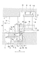
- FIG. 2 is an enlarged view of a main part of the steam turbine according to the first embodiment of the present invention.
- a steam turbine (axial flow rotary machine) 100 according to this embodiment includes a rotating shaft 1, a casing 2, a moving blade stage 3 including a plurality of moving blades 4, and a plurality of stationary blades 7. And a stationary blade stage 6 provided with.
- the rotary shaft 1 has a cylindrical shape extending along the central axis Ac.
- the rotary shaft 1 is supported at both ends in the central axis direction Da along the central axis Ac by the bearing device 5 so as to be rotatable around the central axis Ac.
- the bearing device 5 includes a journal bearing 5A provided on each side of the central axis direction Da of the rotating shaft 1 and a thrust bearing 5B provided only on the first side in the central axis direction Da.
- the journal bearing 5 ⁇ / b> A supports a load in the radial direction Dr by the rotating shaft 1.
- the thrust bearing 5B supports the load in the central axis direction Da by the rotating shaft 1.
- the casing 2 has a cylindrical shape extending in the central axis direction Da.
- the casing 2 covers the rotating shaft 1 from the outer peripheral side.
- the casing 2 includes an intake port 10 and an exhaust port 11.
- the air inlet 10 is formed on the first side in the central axis direction Da of the casing 2 and takes in steam (working fluid) into the casing 2 from the outside.
- the exhaust port 11 is formed on the second side of the casing 2 in the central axis direction Da and exhausts the steam that has passed through the inside of the casing 2 to the outside.
- the side where the intake port 10 is located when viewed from the exhaust port 11 is referred to as the upstream side
- the side where the exhaust port 11 is located when viewed from the intake port 10 is referred to as the downstream side.
- the rotor blade stage 3 is provided with a plurality of stages on the outer peripheral surface 1S of the rotating shaft 1 at intervals from the first side to the second side in the central axis direction Da.
- Each blade stage 3 has a plurality of blades (roof blade members) 4 arranged on the outer peripheral surface 1S of the rotary shaft 1 at intervals in the circumferential direction around the central axis Ac.
- the moving blade 4 includes a platform 43 provided on the outer peripheral surface 1 ⁇ / b> S of the rotating shaft 1, a moving blade body 40, and a moving blade shroud 41.
- the rotor blade body 40 is formed so as to extend radially outward from the platform 43.
- the rotor blade body 40 has an airfoil-shaped cross section as viewed from the radial direction Dr.
- the moving blade shroud 41 is provided at the radially outer end of the moving blade body 40.
- the moving blade shroud 41 is set such that the dimension in the central axis direction Da is larger than the dimension of the moving blade body 40 in the central axis direction Da.
- a moving blade accommodating recess 20 for accommodating the moving blade shroud 41 is formed in an inner peripheral side of the casing 2 and in a region facing the moving blade shroud 41 in the radial direction Dr.
- the moving blade housing recess 20 is recessed from the inner peripheral surface 2S of the casing 2 toward the outer side in the radial direction Dr, and has a groove shape continuous in the circumferential direction around the central axis Ac.
- the blade accommodating recess 20 is provided with a plurality (two) of blade-side fins 42. These blade-side fins 42 have a thin plate shape extending inward in the radial direction Dr. A gap (clearance) extending in the radial direction Dr is formed between the tip of the rotor blade side fin 42 and the rotor blade accommodating recess 20.
- the stationary blade stage 6 is provided with a plurality of stages on the inner peripheral surface of the casing 2 at intervals along the central axis direction Da.
- Each stationary blade stage 6 is arranged on the upstream side of each moving blade stage 3.
- Each stationary blade stage 6 has a plurality of stationary blades 7 arranged at intervals in the circumferential direction around the central axis Ac.
- the stationary blade 7 includes a stationary blade body 70 and a stationary blade shroud 71.
- the stationary blade body 70 is provided so as to extend from the inner peripheral surface 2S of the casing 2 toward the inside in the radial direction Dr.
- the stationary blade body 70 has a blade-shaped cross section as viewed from the radial direction Dr.
- the stationary blade shroud 71 is attached to the end of the stationary blade body 70 on the inner side in the radial direction Dr.
- the radial direction Dr dimensions of the stationary blade body 70 and the moving blade body 40 are the same. In other words, when viewed from the central axis direction Da, the stationary blade body 70 and the moving blade body 40 are arranged so as to overlap each other.
- the outer peripheral surface 1S of the rotary shaft 1 is recessed from the outer peripheral surface 1S toward the inner side in the radial direction Dr.
- a groove-shaped stationary blade housing recess 8 that is continuous in the direction is formed.
- the stationary blade accommodating recess 8 is formed such that the bottom surface 83A on the downstream side in the central axis direction Da is positioned on the inner side in the radial direction Dr than the bottom surface 83B on the upstream side.
- the stationary blade shroud 71 of each stationary blade 7 is accommodated in the stationary blade accommodating recess 8.
- the stationary blade shroud 71 is provided with a plurality (two) of stationary blade side fins 72.
- Each of the stationary blade side fins 72 has a thin plate shape that extends from the stationary blade shroud 71 toward the inside in the radial direction Dr.
- the stationary blade shroud 71 and the stationary blade side fin 72 are provided for the purpose of reducing steam leakage between the rotating shaft 1 and the stationary blade 7.
- the stationary blade side fins 72 located on the upstream side in the central axis direction Da face the bottom surface 83B
- the stationary blade side fins 72 located on the downstream side face the bottom surface 83A.
- the stationary blade side fins 72 and the bottom surfaces 83A and 83B are opposed to each other with a predetermined gap in the radial direction Dr.
- Such a steam turbine 100 further includes a protrusion 45A and a shroud recess 75A.
- the protruding portion 45 ⁇ / b> A is formed in the radial direction Dr intermediate portion of the upstream end surface 43 a of the platform 43.
- the upstream end face 43a is formed so as to face the upstream side of the central axis direction Da and to be orthogonal to the central axis direction Da.
- the protrusion 45A is formed so as to protrude from the upstream end face 43a of the platform 43 toward the upstream side in the central axis direction Da.
- the protrusion 45A has a guide surface 45f on the side facing the inside in the radial direction Dr.
- the guide surface 45f is formed so as to be gradually curved inward in the radial direction Dr with a constant curvature over the entire region of the distal end portion 45t spaced upstream from the base end portion 45s on the upstream end surface 43a side of the platform 43 in the central axis direction Da.
- the outer surface 45h facing the outside in the radial direction Dr in the projecting portion 45A is formed perpendicular to the upstream end surface 43a and parallel to the central axis direction Da.
- the shroud recess 75 ⁇ / b> A is formed on the downstream end surface 71 a of the stationary blade shroud 71.
- the downstream end surface 71a faces the downstream side in the central axis direction Da, is orthogonal to the central axis direction Da, and is formed so as to face the upstream end surface 43a of the platform 43 with a gap in the central axis direction Da. .
- the shroud recess 75A is formed so as to be recessed from the downstream end face 71a toward the upstream side in the central axis direction Da at a position facing the protrusion 45A in the central axis direction Da.
- an inner peripheral wall surface 75a inside the radial direction Dr and an outer peripheral wall surface 75b outside the radial direction Dr are formed in parallel with the central axis direction Da, respectively.
- the upstream wall surface 75c on the upstream side in the central axis direction Da is formed orthogonal to the central axis direction Da.
- the thickness dimension h1 in the radial direction Dr between the inner peripheral wall surface 75a and the surface facing the inner side in the radial direction Dr of the stationary blade shroud 71 is outside the radial direction Dr of the outer circumferential wall surface 75b and the stationary blade shroud 71. It is larger than the thickness dimension h2 in the radial direction Dr between the facing surface.
- the inner peripheral wall surface 75a is formed on the inner side in the radial direction Dr from the guide surface 45f of the protrusion 45A.
- the outer peripheral wall surface 75b of the shroud recess 75A is formed on the outer side in the radial direction Dr with respect to the outer surface 45h of the protrusion 45A.
- the casing 2, the stationary blade 7, the rotating shaft 1, the moving blade 4, and the like may thermally expand in the central axis direction Da due to heat transmitted from the steam during the operation of the steam turbine 100. Furthermore, the amount of thermal expansion in the central axis direction Da may differ between the casing 2 and the stationary blade 7 and the rotating shaft 1 and the moving blade 4.
- the rotary shaft 1 and the rotor blade 4 are displaced relative to the stationary blade 7 in the central axis direction Da due to the difference in thermal elongation, at least a part of the projecting portion 45A is shroud. It can be inserted into the recess 75A.
- the protrusion dimension L1 along the central axis direction Da from the platform 43 in the protrusion 45A is equal to or smaller than the recess dimension L2 along the central axis direction Da in the shroud recess 75A.
- the operation of the steam turbine 100 configured as described above will be described with reference to FIG.
- a steam supply source such as a boiler
- the steam introduced into the casing 2 sequentially collides with the moving blade 4 (the moving blade stage 3) and the stationary blade 7 (the stationary blade stage 6).
- the rotating shaft 1 obtains rotational energy and rotates around the central axis Ac.
- the rotational motion of the rotary shaft 1 is taken out by a generator or the like (not shown) connected to the shaft end. The above cycle is repeated continuously.
- the steam flowing from the upstream side passes through the stationary blades 7 and the moving blades 4 alternately and flows toward the downstream side, thereby forming a mainstream FM.
- the mainstream FM is rectified by sequentially colliding with the stationary blade 7 and the moving blade 4 as described above, and gives energy to the moving blade 4.
- the leak flow FL flowing into the space Vc circulates outward in the radial direction Dr along the upstream end surface 43a of the platform 43, and then collides with the guide surface 45f of the protrusion 45A.
- the leak flow FL that collides with the guide surface 45f changes its direction along the guide surface 45f, and is gradually guided inward in the radial direction Dr while moving from the downstream side to the upstream side in the central axis direction Da. Thereby, the leak flow FL forms a vortex T in the space Vc.
- a part of the component of the vortex T deviates from the vortex T, flows upstream in the central axis direction Da, and flows into the shroud recess 75A formed to face the protrusion 45A.
- the leak flow FL flows into the shroud recess 75A, the leak flow FL is directed toward the upstream side of the central axis direction Da on the inner peripheral wall surface 75a side, and then hits the upstream wall surface 75c and the outer peripheral wall surface 75b, thereby downstream from the radial direction Dr toward the central axis direction Da.
- the direction is changed to the side and flows out downstream of the central axis direction Da.
- the protruding portion 45A that protrudes from the platform 43 toward the upstream side in the central axis direction Da has the guide surface 45f on the side facing the inner side in the radial direction Dr. .
- the guide surface 45f is curved inward in the radial direction Dr from the base end 45s to the tip 45t.
- the flow of the leak flow FL from the inside to the outside in the radial direction Dr is dissipated.
- the momentum of the leak flow FL that flows out of the radial direction Dr from the gap between the stationary blade shroud 71 and the platform 43 of the moving blade 4 is weakened.
- the mixing loss is reduced when the leak flow FL joins the steam main flow FM that alternately passes through the stationary blade body 70 and the moving blade body 40 along the central axis direction Da inside the casing 2. .
- a shroud recess 75A is formed on the stationary blade shroud 71 at a position facing the protruding portion 45A in the central axis direction Da. According to such a configuration, a part of the leak flow FL flows into the shroud recess 75A facing the protrusion 45A. Leakage FL is further weakened by flowing into shroud recess 75A. As a result, the mixing loss when the leak flow FL joins the steam main flow FM is further reduced. In this way, it is possible to further improve the performance of the steam turbine 100 by further reducing the mixing loss when the leak flow FL joins the steam main flow FM.
- the rotating shaft 1 and the moving blade 4 are thermally expanded in the central axis direction Da more than the stationary blade 7 due to the heat of the steam, at least a part of the protruding portion 45A can be inserted into the shroud recess 75A. Yes. Thereby, it can suppress that 45 A of protrusion parts and the stationary blade shroud 71 interfere. Furthermore, since the protrusion dimension L1 of the protrusion 45A from the platform 43 is equal to or less than the recess dimension L2 along the central axis direction Da of the shroud recess 75A, for example, all of the protrusion 45A is inserted into the shroud recess 75A. Even if the moving blade 4 and the stationary blade 7 are relatively displaced, it is possible to suppress the interference between the protruding portion 45A and the shroud recess 75A.
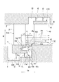
- FIG. 3 is an enlarged view of a main part of the steam turbine according to the second embodiment of the present invention.
- the steam turbine 100 in this embodiment further includes a protrusion 45 ⁇ / b> B and a shroud recess 75 ⁇ / b> B.
- the protruding portion 45 ⁇ / b> B is formed at the radial direction Dr intermediate portion of the upstream end surface 43 a of the platform 43.
- the protrusion 45B is formed so as to protrude from the upstream end face 43a of the platform 43 toward the upstream side in the central axis direction Da.
- the protrusion 45B has a guide surface 45f on the side facing the radial direction Dr.
- the guide surface 45f is formed to be gradually curved with a certain curvature inward in the radial direction Dr from the base end portion 45s of the upstream end surface 43a of the platform 43 toward the tip end portion 45t on the upstream side in the central axis direction Da.
- the protrusion 45B has an outer peripheral guide surface 45g that is gradually inclined or curved outward in the radial direction Dr from the upstream side toward the downstream side in the central axis direction Da toward the outer side in the radial direction Dr. have.
- the shroud recess 75 ⁇ / b> B is formed on the downstream end surface 71 a of the stationary blade shroud 71.
- the shroud recess 75B is formed on the downstream end surface 71a so as to be recessed toward the upstream side in the central axial direction Da at a position facing the protruding portion 45B in the central axial direction Da.
- the shroud recess 75B is formed such that the inner peripheral wall surface 75a inside the radial direction Dr is parallel to the central axis Ac.
- the upstream wall surface 75d on the upstream side in the central axis direction Da is formed orthogonal to the central axis direction Da.
- an outer peripheral wall surface 75f located on the outer side in the radial direction Dr is gradually curved outward in the radial direction Dr from the upstream side to the downstream side in the central axis direction Da.
- the outer peripheral wall surface 75f is preferably formed with substantially the same radius of curvature as the outer peripheral guide surface 45g of the protrusion 45B.
- the protruding dimension L1 along the central axis direction Da from the platform 43 in the protruding part 45B is equal to or smaller than the hollow dimension L2 along the central axis direction Da in the shroud recess 75B.
- the steam flowing from the upstream side passes through the stationary blades 7 and the moving blades 4 alternately and flows toward the downstream side, thereby forming the mainstream FM.
- components other than the main flow FM flow toward the inside of the stationary blade housing recess 8 to form a leak flow FL.
- a part of the leak flow FL flows into the space Vc between the downstream end surface 71 a of the stationary blade shroud 71 and the upstream end surface 43 a of the platform 43.
- the leak flow FL flowing into the space Vc circulates outward in the radial direction Dr along the upstream end surface 43a of the platform 43, and then collides with the guide surface 45f of the protrusion 45B.
- the leak flow FL that collides with the guide surface 45f changes its direction along the guide surface 45f, and is gradually guided inward in the radial direction Dr while moving from the downstream side to the upstream side in the central axis direction Da. Thereby, the leak flow FL forms a vortex T in the space Vc.
- a part of the component of the vortex T deviates from the vortex T, flows to the upstream side in the central axis direction Da, and flows into the shroud recess 75B formed to face the protruding portion 45B.
- the leak flow FL flows into the shroud recess 75B, the leak flow FL is directed toward the upstream side of the central axial direction Da on the inner peripheral wall surface 75a side, and then hits the upstream wall surface 75d and the outer peripheral wall surface 75f. The direction is changed to the side and flows out downstream of the central axis direction Da.
- the leak flow FL that has flowed out from the shroud recess 75B to the downstream side in the central axis direction Da is guided outward in the radial direction Dr toward the downstream side in the central axis direction Da along the outer peripheral guide surface 45g of the protrusion 45B. It flows out to the outside in the radial direction Dr and joins the mainstream FM.
- the vortex T is generated when the leak flow FL hits the guide surface 45f as in the first embodiment, and the leak flow FL directed from the inside to the outside in the radial direction Dr.
- the flow of is dissipated.
- the momentum of the leak flow FL that flows out of the radial direction Dr from the gap between the stationary blade shroud 71 and the platform 43 of the moving blade 4 is weakened.
- the leak flow FL flows into the shroud recess 75B, and the momentum is further weakened.
- the outer peripheral wall surface 75f of the shroud recess 75B and the outer peripheral guide surface 45g of the protrusion 45B are curved outward in the radial direction Dr from the upstream side toward the downstream side in the central axis direction Da. Accordingly, the leak flow FL is gradually guided outward in the radial direction Dr from the upstream side toward the downstream side in the central axial direction Da along the outer peripheral wall surface 75f of the shroud recess 75B and the outer peripheral guide surface 45g of the protrusion 45B.
- the angle at which the leak flow FL intersects the steam main flow FM is smaller than a right angle. As a result, the mixing loss when the leak flow FL joins the steam main flow FM is further reduced.
- FIG. 4 is an enlarged view of a main part of a steam turbine according to a modification of the second embodiment of the present invention.
- the entire outer peripheral guide surface 45 g of the protrusion 45 ⁇ / b> B may be located on the inner side of the radial direction Dr than the surface 43 d of the platform 43 facing the outer side of the radial direction Dr.
- first and second embodiments are different from the first and second embodiments only in the configuration including the inner peripheral side protruding portion 78 and the platform concave portion 48. Will be described, and redundant description will be omitted.
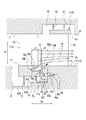
- FIG. 5 is an enlarged view of a main part of the steam turbine according to the third embodiment of the present invention.
- the steam turbine 100 according to this embodiment includes an inner peripheral protrusion 78 and a platform recess 48 in addition to the protrusion 45B and the platform recess 48 shown in the second embodiment. Further prepare.
- the inner peripheral side protruding portion 78 is formed on the inner side in the radial direction Dr than the protruding portion 45B.
- the inner peripheral side protruding portion 78 protrudes from the downstream end surface 71a of the stationary blade shroud 71 to the downstream side in the central axis direction Da.
- the inner peripheral side protruding portion 78 has a guide surface 78f on the side facing the inner side in the radial direction Dr.
- the guide surface 78f is formed to be gradually curved with a constant curvature from the downstream end surface 71a of the stationary blade shroud 71 toward the downstream side of the central axis direction Da in the radial direction Dr.
- the inner peripheral side protruding portion 78 has an outer peripheral side guide surface 78g that is curved outward in the radial direction Dr from the downstream side in the central axis direction Da toward the outer side in the radial direction Dr. have.
- the platform recess 48 is formed in the platform 43 at a position facing the inner peripheral side protruding portion 78 in the central axis direction Da.
- the platform recess 48 is formed to be recessed toward the downstream side in the central axis direction Da with respect to the upstream end surface 43a of the platform 43.
- the platform recess 48 is formed such that the inner peripheral wall surface 48a inside the radial direction Dr is parallel to the central axis Ac.
- an outer peripheral wall surface 48f located on the outer side in the radial direction Dr is curved outward in the radial direction Dr from the downstream side toward the upstream side in the central axis direction Da.
- the outer peripheral wall surface 48f is preferably formed with substantially the same radius of curvature as the outer peripheral guide surface 78g of the inner peripheral protrusion 78.
- the inner peripheral side protruding portion 78 is inserted into the platform recessed portion 48. It is possible. Furthermore, the inner peripheral side protruding portion 78 can be entirely inserted into the platform recess 48 when the rotating shaft 1 and the moving blade 4 are displaced relative to the stationary blade 7 in the central axis direction Da. ing.
- the leak flow FL flowing into the space Vc flows to the outside of the radial direction Dr, and then collides with the guide surface 78f of the inner peripheral side protruding portion 78 to change its direction, thereby forming a vortex T2.
- a part of the component of the vortex T2 deviates from the vortex T2 and flows into the platform recess 48 facing the inner peripheral protrusion 78 on the downstream side in the central axis direction Da.
- the leak flow FL flows into the platform recess 48, the leak flow FL is directed toward the downstream side in the central axial direction Da on the inner peripheral wall surface 48 a side, and then sequentially contacts the outer peripheral wall surface 48 f so as to sequentially reach the upstream side in the central axial direction Da from the radial direction Dr.
- the direction is changed and the gas flows out to the upstream side in the central axis direction Da.
- the leak flow FL that has flowed out from the platform recess 48 to the upstream side in the central axial direction Da sequentially passes through the protrusion 45B and the shroud recess 75B, and then flows out from the space Vc to the outside in the radial direction Dr. Join.
- the leak flow FL hits the inner peripheral side protruding portion 78 inside the protruding portion 45B in the radial direction Dr and flows into the platform concave portion 48. Thereby, the flow of the leak flow FL from the inside in the radial direction Dr to the outside is further dissipated.
- the inner peripheral side protruding portion 78, the platform recessed portion 48, the protruding portion 45B, and the shroud recessed portion 75B are provided in a plurality of stages from the inner side to the outer side in the radial direction Dr. Further, the mixing loss when the leak flow FL joins is further reduced. As a result, the performance of the steam turbine 100 can be improved.
- this invention is not limited to each embodiment mentioned above, In the range which does not deviate from the meaning of this invention, what added the various change to the embodiment mentioned above is included. That is, the specific shapes, configurations, and the like given in the embodiment are merely examples, and can be changed as appropriate.
- the guide surfaces 45f and 78f, the outer peripheral guide surfaces 45g and 78g, and the outer peripheral wall surfaces 48f and 75f are curved surfaces, but these can also be flat inclined surfaces.
- the aspect of the axial-flow rotating machine is not limited to the steam turbine 100, and other devices such as a gas turbine and an aircraft jet engine can be applied as the axial-flow rotating machine.
- the number of moving blade stages 3 and stationary blade stages 6 in the steam turbine 100 are not limited by the above-described embodiment, and may be appropriately determined according to the design and specifications.
Landscapes
- Engineering & Computer Science (AREA)
- Mechanical Engineering (AREA)
- General Engineering & Computer Science (AREA)
- Chemical & Material Sciences (AREA)
- Combustion & Propulsion (AREA)
- Turbine Rotor Nozzle Sealing (AREA)
Abstract
蒸気タービンは、回転軸(1)と、プラットフォーム(43)及び動翼本体(40)を有する動翼(4)と、ケーシング(2)と、静翼本体(70)及び静翼シュラウド(71)を有する静翼(7)と、プラットフォーム(43)から中心軸方向(Da)上流側に向かって突出する突出部(45A)と、を備える。突出部(45A)は、径方向内側を向く側に、プラットフォーム(43)側の基端部(45s)から中心軸方向(Da)上流側の先端部(45t)にわたって、径方向内側に漸次湾曲したガイド面(45f)を有している。
Description
本発明は、軸流回転機械、動翼部材に関する。
本願は、2017年2月17日に出願された特願2017-027928号に基づき優先権を主張し、その内容をここに援用する。
本願は、2017年2月17日に出願された特願2017-027928号に基づき優先権を主張し、その内容をここに援用する。
蒸気タービン、ガスタービン等の軸流回転機械において、ケーシングと、ケーシングの内部に回転自在に設けられた回転軸と、ケーシングの内周部に固定配置された静翼と、この静翼の下流側において回転軸に放射状に設けられた動翼と、を備えたものが知られている。
例えば蒸気タービンの場合、蒸気の圧力エネルギーを静翼によって速度エネルギーに変換し、この速度エネルギーを動翼によって回転エネルギー(機械エネルギー)に変換している。また、動翼内で圧力エネルギーが速度エネルギーに変換され、蒸気が噴出する反動力により回転エネルギー(機械エネルギー)に変換される場合もある。
例えば蒸気タービンの場合、蒸気の圧力エネルギーを静翼によって速度エネルギーに変換し、この速度エネルギーを動翼によって回転エネルギー(機械エネルギー)に変換している。また、動翼内で圧力エネルギーが速度エネルギーに変換され、蒸気が噴出する反動力により回転エネルギー(機械エネルギー)に変換される場合もある。
この種の回転機械では、静翼の先端部と回転軸との間に、径方向の隙間が形成されている。この隙間を蒸気等の作動流体が通過(漏洩)することがある。静翼の先端部と回転軸との隙間を通過する作動流体は、静翼による圧力エネルギーの速度エネルギーへの変換に寄与せず、下流側の動翼に対して回転力をほとんど付与しない。したがって、回転機械の性能向上のためには、前記の隙間を通過する漏洩蒸気の量を低減することが重要となる。
作動流体の漏洩量を低減するための技術として、例えば、特許文献1には、静翼ハブシュラウドに対して軸線方向で対向する動翼ハブに、上流側に向かって突出する抑制板を備える構成が開示されている。
しかしながら、上記特許文献1に記載された構成では、抑制板の上流側の先端部と静翼ハブシュラウドとの間に、軸線方向の間隙が形成される。このため、この抑制板の先端部と静翼ハブシュラウドとの間隙を通じて、作動流体の漏れを生じる。加えて、抑制板の先端部と静翼ハブシュラウドとの間隙を通じた作動流体の漏れ流れは、回転軸の回転による遠心力によって回転軸の径方向内側から外側に向かい、軸線方向に流れる作動流体の主流に交差するようにして合流する。このように、作動流体の主流と作動流体の漏れ流れとが交差して衝突・混合する場合、混合損失と呼ばれるエネルギー損失が発生することが知られている。混合損失の増加は、軸流回転機械の効率向上の妨げとなる場合がある。
本発明は、作動流体の主流と作動流体の漏れ流れとの混合損失を低減し、軸流回転機械の性能向上を図る軸流回転機械、動翼部材を提供することを目的とする。
本発明は、上記課題を解決するため、以下の手段を採用する。
本発明の第一の態様では、中心軸回りに回転する回転軸と、前記回転軸の径方向外側に設けられたプラットフォーム、及び、前記プラットフォームから径方向外側に向かって延びるよう設けられた動翼本体を有する動翼と、前記回転軸及び前記動翼の径方向外側に配置され、その径方向内側を作動流体が前記中心軸方向に沿って上流側から下流側に向かって流れる筒状のケーシングと、前記動翼に対して前記中心軸方向上流側に設けられ、前記ケーシングから径方向内側に向かって延びるよう設けられた静翼本体、及び前記静翼本体の径方向内側に設けられた静翼シュラウドを有する静翼と、前記プラットフォームから前記中心軸方向上流側に向かって突出する突出部と、を備える。前記突出部は、径方向内側を向く側に、前記プラットフォーム側の基端部から前記中心軸方向上流側の先端部にわたって、径方向内側に漸次傾斜又は湾曲したガイド面を有している。
本発明の第一の態様では、中心軸回りに回転する回転軸と、前記回転軸の径方向外側に設けられたプラットフォーム、及び、前記プラットフォームから径方向外側に向かって延びるよう設けられた動翼本体を有する動翼と、前記回転軸及び前記動翼の径方向外側に配置され、その径方向内側を作動流体が前記中心軸方向に沿って上流側から下流側に向かって流れる筒状のケーシングと、前記動翼に対して前記中心軸方向上流側に設けられ、前記ケーシングから径方向内側に向かって延びるよう設けられた静翼本体、及び前記静翼本体の径方向内側に設けられた静翼シュラウドを有する静翼と、前記プラットフォームから前記中心軸方向上流側に向かって突出する突出部と、を備える。前記突出部は、径方向内側を向く側に、前記プラットフォーム側の基端部から前記中心軸方向上流側の先端部にわたって、径方向内側に漸次傾斜又は湾曲したガイド面を有している。
このような構成によれば、静翼シュラウドと動翼のプラットフォームとの間隙(キャビティ)を通じ、径方向内側から外側に向かう作動流体の漏れ流れは、突出部の径方向内側に形成されたガイド面に当たる。ガイド面は、プラットフォーム側の基端部から上流側の先端部にわたって径方向内側に傾斜又は湾曲しているので、作動流体の漏れ流れは、このガイド面によって、径方向内側に戻るように渦を生成する。このようにして渦が生成されることで、径方向内側から外側に向かう作動流体の漏れ流れが散逸される。これにより、静翼シュラウドと動翼のプラットフォームの間隙から径方向外側に流れ出る作動流体の漏れ流れの勢いが弱まる。その結果、ケーシングの内側で、中心軸方向に沿って静翼本体と動翼本体とを交互に経る作動流体の主流に、作動流体の漏れ流れが合流するときの混合損失が低減される。
本発明の第二の態様では、上記第一の態様において、前記静翼シュラウドに形成され、前記突出部に対して前記中心軸方向で対向し、前記中心軸方向上流側に向かって窪むシュラウド凹部をさらに備えていてもよい。
このような構成によれば、静翼シュラウドと動翼のプラットフォームと間隙を径方向内側から外側に向かって流れる作動流体の漏れ流れの一部は、突出部のガイド面に沿って、突出部に対向するシュラウド凹部に流れ込む。作動流体の漏れ流れは、シュラウド凹部に流れ込むことで、その勢いがさらに弱まる。その結果、作動流体の主流に作動流体の漏れ流れが合流するときの混合損失がさらに低減される。
本発明の第三の態様では、上記第二の態様において、前記シュラウド凹部は、前記径方向外側に位置する外側周壁面が、前記中心軸方向上流側から下流側に向かって径方向外側に漸次傾斜又は湾曲していてもよい。
このような構成によれば、シュラウド凹部に流れ込んだ作動流体の漏れ流れは、シュラウド凹部の外側周壁面に沿って、中心軸方向上流側から下流側に向かって漸次径方向外側に案内される。これによって作動流体の漏れ流れが作動流体の主流に交差する角度が直角よりも小さくなる。その結果、作動流体の主流に作動流体の漏れ流れが合流するときの混合損失がさらに低減される。
本発明の第四の態様では、上記第二又は第三の態様において、前記突出部は、径方向外側を向く側に、前記中心軸方向上流側から下流側に向かって径方向外側に漸次傾斜又は湾曲している外周側ガイド面をさらに有していてもよい。
このような構成によれば、シュラウド凹部から下流側に流れ出た作動流体の漏れ流れが、突出部の外周側ガイド面に沿うように流れることで、この作動流体の漏れ流れは、中心軸方向上流側から下流側に向かって漸次径方向外側に案内される。これによって作動流体の漏れ流れが作動流体の主流に交差する角度を小さくし、作動流体の主流に作動流体の漏れ流れが合流するときの混合損失がさらに低減される。
本発明の第五の態様によれば、上記第二から第四の態様において、前記静翼に対し、前記回転軸及び前記動翼が前記中心軸方向に相対的に変位したとき、前記突出部の少なくとも一部は、前記シュラウド凹部内に挿入可能であるようにしてもよい。
このような構成によれば、作動流体の熱によって、回転軸及び動翼が、静翼よりも大きく中心軸方向に熱伸びした場合、突出部の少なくとも一部がシュラウド凹部内に挿入されることによって、突出部と静翼シュラウドとが干渉することを抑制できる。
本発明の第六の態様によれば、上記第五の態様において、前記突出部における前記プラットフォームからの前記中心軸方向に沿った突出寸法は、前記シュラウド凹部における前記中心軸方向に沿った窪み寸法以下であってもよい。
このような構成によれば、突出部の全てがシュラウド凹部内に挿入されても、突出部とシュラウド凹部とが干渉することを抑制できる。
本発明の第七の態様によれば、上記第一から第六の態様において、前記突出部よりも径方向内側に形成され、前記静翼シュラウドから前記中心軸方向下流側に突出する内周側突出部、をさらに備えてもよい。
このような構成によれば、静翼シュラウドと動翼のプラットフォームと間隙を通じ、径方向内側から外側に向かって流れる作動流体の漏れ流れは、突出部よりも径方向内側の内周側突出部に当たる。これにより、径方向内側から外側に向かう作動流体の漏れ流れが、さらに散逸される。その結果、作動流体の主流に作動流体の漏れ流れが合流するときの混合損失が、さらに低減される。
本発明の第八態様によれば、上記第七の態様において、前記プラットフォームに形成され、前記内周側突出部に対して前記中心軸方向で対向し、前記中心軸方向下流側に向かって窪むプラットフォーム凹部をさらに備えてもよい。
このような構成によれば、内周側突出部に当たった作動流体の漏れ流れの一部は、内周側突出部に対向するプラットフォーム凹部に流れ込む。作動流体の漏れ流れは、プラットフォーム凹部に流れ込むことで、その勢いがさらに弱まる。その結果、作動流体の主流に作動流体の漏れ流れが合流するときの混合損失がさらに低減される。
本発明の第九態様によれば、回転軸の径方向外側に設けられるプラットフォームと、前記プラットフォームから径方向外側に向かって延びるよう設けられた動翼本体と、前記プラットフォームから前記回転軸の中心軸方向上流側に向かって突出する突出部と、を備える。前記突出部は、径方向内側を向く側に、前記プラットフォーム側の基端部から前記中心軸方向に沿って離間した先端部にわたって、径方向内側に漸次傾斜又は湾曲したガイド面を有している。
このような構成によれば、上記構成の動翼部材を軸流回転機械に組み込むことで、静翼シュラウドと動翼のプラットフォームの間隙から径方向外側に流れ出る作動流体の漏れ流れの勢いを弱めることができる。その結果、ケーシングの内側で、中心軸方向に沿って静翼本体と動翼本体とを交互に経る作動流体の主流に、作動流体の漏れ流れが合流するときの混合損失を低減することができる。
本発明に係る軸流回転機械、動翼部材によれば、作動流体の主流と作動流体の漏れ流れとの混合損失を低減し、軸流回転機械の性能向上を図ることが可能となる。
以下、本発明の一実施形態に係る軸流回転機械、動翼部材を図面に基づき説明する。(第一実施形態)
図1は、本発明の実施形態に係る蒸気タービンの構成を示す模式図である。図2は、本発明の第一実施形態に係る蒸気タービンの要部拡大図である。
図1に示すように、本実施形態に係る蒸気タービン(軸流回転機械)100は、回転軸1と、ケーシング2と、複数の動翼4を備える動翼段3と、複数の静翼7を備える静翼段6と、を備えている。
図1は、本発明の実施形態に係る蒸気タービンの構成を示す模式図である。図2は、本発明の第一実施形態に係る蒸気タービンの要部拡大図である。
図1に示すように、本実施形態に係る蒸気タービン(軸流回転機械)100は、回転軸1と、ケーシング2と、複数の動翼4を備える動翼段3と、複数の静翼7を備える静翼段6と、を備えている。
回転軸1は、中心軸Acに沿って延びる円柱状をなしている。回転軸1は、中心軸Acに沿った中心軸方向Daの両端部が、軸受装置5によって中心軸Ac回りに回転自在に支持されている。軸受装置5は、回転軸1の中心軸方向Da両側に1つずつ設けられたジャーナル軸受5Aと、中心軸方向Daの第一側のみに設けられたスラスト軸受5Bと、を有している。ジャーナル軸受5Aは、回転軸1による径方向Drへの荷重を支持する。スラスト軸受5Bは、回転軸1による中心軸方向Daへの荷重を支持する。
ケーシング2は、中心軸方向Daに延びる筒状をなしている。ケーシング2は、回転軸1を外周側から覆う。
ケーシング2は、吸気口10と、排気口11と、を備えている。吸気口10は、ケーシング2の中心軸方向Daの第一側に形成され、外部からケーシング2内に蒸気(作動流体)を取り入れる。排気口11は、ケーシング2の中心軸方向Daの第二側に形成され、ケーシング2内部を通過した蒸気を外部に排気する。
以降の説明では、排気口11から見て吸気口10が位置する側を上流側と呼び、吸気口10から見て排気口11が位置する側を下流側と呼ぶ。
ケーシング2は、吸気口10と、排気口11と、を備えている。吸気口10は、ケーシング2の中心軸方向Daの第一側に形成され、外部からケーシング2内に蒸気(作動流体)を取り入れる。排気口11は、ケーシング2の中心軸方向Daの第二側に形成され、ケーシング2内部を通過した蒸気を外部に排気する。
以降の説明では、排気口11から見て吸気口10が位置する側を上流側と呼び、吸気口10から見て排気口11が位置する側を下流側と呼ぶ。
動翼段3は、回転軸1の外周面1Sに、中心軸方向Daの第一側から第二側に向かって間隔をあけて、複数段が設けられている。各動翼段3は、回転軸1の外周面1S上で、中心軸Ac回りの周方向に間隔をあけて配列された複数の動翼(動翼部材)4を有している。
図2に示すように、動翼4は、回転軸1の外周面1Sに設けられたプラットフォーム43と、動翼本体40と、動翼シュラウド41と、を有している。
詳しくは図示しないが、動翼本体40は、プラットフォーム43から径方向外側に向かって延びるよう形成されている。動翼本体40は、径方向Drから見て翼型の断面を有している。
動翼シュラウド41は、動翼本体40の径方向外側の端部に設けられている。動翼シュラウド41は、中心軸方向Daにおける寸法が、同中心軸方向Daにおける動翼本体40の寸法よりも大きく設定されている。
動翼シュラウド41は、動翼本体40の径方向外側の端部に設けられている。動翼シュラウド41は、中心軸方向Daにおける寸法が、同中心軸方向Daにおける動翼本体40の寸法よりも大きく設定されている。
ケーシング2の内周側であって、動翼シュラウド41と径方向Drで対向する領域には、動翼シュラウド41を収容するための動翼収容凹部20が形成されている。動翼収容凹部20は、ケーシング2の内周面2Sから径方向Dr外側に向かって窪み、中心軸Ac回りの周方向に連続する溝状をなしている。
動翼収容凹部20には、複数(2つ)の動翼側フィン42が設けられている。これら動翼側フィン42は、径方向Dr内側に向かって延びる薄板状をなしている。動翼側フィン42の先端部と、動翼収容凹部20との間には、径方向Drに広がる間隙(クリアランス)が形成される。
図1に示すように、静翼段6は、ケーシング2の内周面に、中心軸方向Daに沿って間隔をあけて、複数段が設けられている。各静翼段6は、各動翼段3の上流側に配置されている。各静翼段6は、中心軸Ac回りの周方向に間隔をあけて配列された複数の静翼7を有している。
図2に示すように、静翼7は、静翼本体70と、静翼シュラウド71と、を備えている。
静翼本体70は、ケーシング2の内周面2Sから径方向Dr内側に向かって延びるよう設けられている。静翼本体70は、径方向Drから見て翼型の断面を有している。
静翼シュラウド71は、静翼本体70の径方向Dr内側の端部に取り付けられている。
静翼本体70は、ケーシング2の内周面2Sから径方向Dr内側に向かって延びるよう設けられている。静翼本体70は、径方向Drから見て翼型の断面を有している。
静翼シュラウド71は、静翼本体70の径方向Dr内側の端部に取り付けられている。
本実施形態では、静翼本体70と動翼本体40の径方向Dr寸法は互いに同一とされている。言い換えると、中心軸方向Daから見た場合、静翼本体70と動翼本体40とは互いに重なるように配列されている。
回転軸1の径方向Dr外側を向く外周面1S上において、各動翼段3の上流側には、回転軸1の外周面1Sから径方向Dr内側に向かって窪み、中心軸Ac回りの周方向に連続する溝状の静翼収容凹部8が形成されている。この実施形態において、静翼収容凹部8は、中心軸方向Da下流側の底面83Aが、上流側の底面83Bよりも径方向Drの内側に位置するよう形成されている。
各静翼7の静翼シュラウド71は、静翼収容凹部8内に収容されている。
各静翼7の静翼シュラウド71は、静翼収容凹部8内に収容されている。
静翼シュラウド71には、複数(2つ)の静翼側フィン72が設けられている。これらの静翼側フィン72は、いずれも静翼シュラウド71から径方向Dr内側に向かって延びる薄板状をなしている。静翼シュラウド71及び静翼側フィン72は、回転軸1と静翼7との間における蒸気の漏れを低減することを目的として設けられる。2つの静翼側フィン72のうち、中心軸方向Da上流側に位置する静翼側フィン72は底面83Bに対向し、下流側に位置する静翼側フィン72は底面83Aに対向している。これら静翼側フィン72と底面83A、83Bは、径方向Drに所定の間隙を隔てて対向している。
このような蒸気タービン100は、突出部45Aと、シュラウド凹部75Aと、をさらに備える。
突出部45Aは、プラットフォーム43の上流側端面43aの径方向Dr中間部に形成されている。上流側端面43aは、中心軸方向Daの上流側を向いて中心軸方向Daに直交するよう形成されている。突出部45Aは、プラットフォーム43の上流側端面43aから中心軸方向Da上流側に向かって突出するよう形成されている。
この実施形態において、突出部45Aは、径方向Dr内側を向く側にガイド面45fを有している。ガイド面45fは、プラットフォーム43の上流側端面43a側の基端部45sから中心軸方向Da上流側に離間した先端部45tの全域にわたって、一定の曲率で径方向Dr内側に漸次湾曲して形成されている。また、この実施形態において、突出部45Aにおいて径方向Dr外側を向く外側面45hは、上流側端面43aに直交して中心軸方向Daと平行に形成されている。
シュラウド凹部75Aは、静翼シュラウド71の下流側端面71aに形成されている。下流側端面71aは、中心軸方向Daの下流側を向いて中心軸方向Daに直交し、プラットフォーム43の上流側端面43aに対し、中心軸方向Daに間隙を隔てて対向するよう形成されている。
シュラウド凹部75Aは、突出部45Aに対して中心軸方向Daで対向する位置に、下流側端面71aから中心軸方向Da上流側に向かって窪むように形成されている。この実施形態において、シュラウド凹部75Aは、径方向Dr内側の内側周壁面75aと径方向Dr外側の外側周壁面75bとが、それぞれ中心軸方向Daと平行に形成されている。シュラウド凹部75Aにおいて、中心軸方向Da上流側の上流壁面75cは、中心軸方向Daに直交して形成されている。
また、内側周壁面75aと静翼シュラウド71の径方向Drの内側を向く面との間の径方向Drの肉厚寸法h1は、外側周壁面75bと静翼シュラウド71の径方向Drの外側を向く面との間の径方向Drの肉厚寸法h2よりも大きくなっている。
また、内側周壁面75aと静翼シュラウド71の径方向Drの内側を向く面との間の径方向Drの肉厚寸法h1は、外側周壁面75bと静翼シュラウド71の径方向Drの外側を向く面との間の径方向Drの肉厚寸法h2よりも大きくなっている。
このシュラウド凹部75Aは、内側周壁面75aが突出部45Aのガイド面45fよりも径方向Dr内側に形成されている。シュラウド凹部75Aの外側周壁面75bは、突出部45Aの外側面45hよりも径方向Dr外側に形成されている。
ここで、ケーシング2、静翼7、回転軸1、動翼4等は、蒸気タービン100の作動中に蒸気から伝わる熱によって中心軸方向Daに熱伸びする場合がある。さらに、ケーシング2及び静翼7と、回転軸1及び動翼4との間では、中心軸方向Daの熱伸び量が異なる場合が有る。
シュラウド凹部75Aは、回転軸1及び動翼4が、上記熱伸び量の違いによって、静翼7に対して中心軸方向Daに相対的に変位したとき、突出部45Aの少なくとも一部が、シュラウド凹部75A内に挿入可能となっている。
さらに、突出部45Aにおけるプラットフォーム43からの中心軸方向Daに沿った突出寸法L1は、シュラウド凹部75Aにおける中心軸方向Daに沿った窪み寸法L2以下となっている。これにより、回転軸1及び動翼4が、静翼7に対して中心軸方向Daに相対的に変位したとき、突出部45Aの全体が、シュラウド凹部75A内に挿入可能となっている。
シュラウド凹部75Aは、回転軸1及び動翼4が、上記熱伸び量の違いによって、静翼7に対して中心軸方向Daに相対的に変位したとき、突出部45Aの少なくとも一部が、シュラウド凹部75A内に挿入可能となっている。
さらに、突出部45Aにおけるプラットフォーム43からの中心軸方向Daに沿った突出寸法L1は、シュラウド凹部75Aにおける中心軸方向Daに沿った窪み寸法L2以下となっている。これにより、回転軸1及び動翼4が、静翼7に対して中心軸方向Daに相対的に変位したとき、突出部45Aの全体が、シュラウド凹部75A内に挿入可能となっている。
以上のように構成された蒸気タービン100の動作について図1を参照して説明する。蒸気タービン100を運転するに当たっては、まずボイラ等の蒸気供給源(図示省略)から供給された高温高圧の蒸気が、吸気口10を通じてケーシング2の内部に導入される。ケーシング2内に導入された蒸気は、動翼4(動翼段3)、及び静翼7(静翼段6)に順次衝突する。これにより、回転軸1は回転エネルギーを得て、中心軸Ac回りに回転する。
回転軸1の回転運動は、軸端に連結された発電機等(図示省略)によって取り出される。以上のサイクルが連続的に繰り返される。
回転軸1の回転運動は、軸端に連結された発電機等(図示省略)によって取り出される。以上のサイクルが連続的に繰り返される。
上流側から流れてきた蒸気は、静翼7と動翼4とを交互に経て、下流側に向かって流れることで、主流FMを形成する。この主流FMは、上記のように静翼7と動翼4とに順次衝突することで整流されるとともに、動翼4に対してエネルギーを与える。
一方で、上流側から流れてきた蒸気のうち、主流FMを除く成分は、上記の静翼収容凹部8内に向かって流れることで、リーク流(漏れ流れ)FLを形成する。このリーク流FLの大部分は、静翼シュラウド71に設けられた静翼側フィン72によって阻止される。しかしながら、静翼側フィン72と静翼収容凹部8の底面83A,83Bとの間にはクリアランスが形成されていることから、リーク流FLの一部の成分が、クリアランスを通じて下流側の、静翼シュラウド71の下流側端面71aとプラットフォーム43の上流側端面43aとの間の空間Vcに流れ込む。
空間Vc内に流れ込んだリーク流FLは、プラットフォーム43の上流側端面43aに沿って径方向Dr外側に流通した後、突出部45Aのガイド面45fに衝突する。ガイド面45fに衝突したリーク流FLは、ガイド面45fに沿って向きを変え、中心軸方向Daの下流側から上流側に向かいつつ、漸次径方向Dr内側に案内される。これにより、リーク流FLは、空間Vc内で渦Tを形成する。
さらに、この渦Tの一部の成分は、渦Tから逸脱して、中心軸方向Daの上流側に流れ、突出部45Aに対向して形成されたシュラウド凹部75Aに流れ込む。リーク流FLは、シュラウド凹部75Aに流れ込むと、内側周壁面75a側で中心軸方向Da上流側に向かった後、上流壁面75c、外側周壁面75bに当たることで径方向Dr外側から中心軸方向Da下流側に向きを変え、中心軸方向Da下流側に流出する。
シュラウド凹部75Aから中心軸方向Da下流側に流出したリーク流FLは、空間Vcから径方向Dr外側に流れ出て主流FMに合流し、中心軸方向Da下流側に流れていく。
シュラウド凹部75Aから中心軸方向Da下流側に流出したリーク流FLは、空間Vcから径方向Dr外側に流れ出て主流FMに合流し、中心軸方向Da下流側に流れていく。
上述したような蒸気タービン100及び動翼4によれば、プラットフォーム43から中心軸方向Da上流側に向かって突出する突出部45Aが、径方向Dr内側を向く側にガイド面45fを有している。このガイド面45fは、基端部45sから先端部45tにわたって径方向Dr内側に湾曲している。これにより、静翼シュラウド71と動翼4のプラットフォーム43と間隙を通じ、径方向Dr内側から外側に向かって流れるリーク流FLは、ガイド面45fに当たることによって、渦Tを生成する。渦Tが生成されることで、径方向Dr内側から外側に向かうリーク流FLの流れが散逸される。これにより、静翼シュラウド71と動翼4のプラットフォーム43の間隙から径方向Dr外側に流れ出るリーク流FLの勢いが弱まる。その結果、ケーシング2の内側で、中心軸方向Daに沿って静翼本体70と動翼本体40とを交互に経る蒸気の主流FMに、リーク流FLが合流するときの混合損失が低減される。
また、静翼シュラウド71に、突出部45Aに対して中心軸方向Daで対向する位置に、シュラウド凹部75Aが形成されている。このような構成によれば、リーク流FLの一部は、突出部45Aに対向するシュラウド凹部75Aに流れ込む。リーク流FLは、シュラウド凹部75Aに流れ込むことで、その勢いがさらに弱まる。その結果、蒸気の主流FMにリーク流FLが合流するときの混合損失がさらに低減される。
このようにして、蒸気の主流FMにリーク流FLが合流するときの混合損失がさらに低減されることで、蒸気タービン100の性能向上を図ることが可能となる。
このようにして、蒸気の主流FMにリーク流FLが合流するときの混合損失がさらに低減されることで、蒸気タービン100の性能向上を図ることが可能となる。
また、蒸気の熱によって、回転軸1及び動翼4が、静翼7よりも中心軸方向Daに大きく熱伸びした場合、突出部45Aの少なくとも一部がシュラウド凹部75A内に挿入可能となっている。これによって、突出部45Aと静翼シュラウド71とが干渉することを抑制できる。
さらに、突出部45Aにおけるプラットフォーム43からの突出寸法L1は、シュラウド凹部75Aにおける中心軸方向Daに沿った窪み寸法L2以下であるので、例え、突出部45Aの全てがシュラウド凹部75A内に挿入される程、動翼4と静翼7とが相対変位しても、突出部45Aとシュラウド凹部75Aとが干渉することを抑制できる。
さらに、突出部45Aにおけるプラットフォーム43からの突出寸法L1は、シュラウド凹部75Aにおける中心軸方向Daに沿った窪み寸法L2以下であるので、例え、突出部45Aの全てがシュラウド凹部75A内に挿入される程、動翼4と静翼7とが相対変位しても、突出部45Aとシュラウド凹部75Aとが干渉することを抑制できる。
(第二実施形態)
次に、本発明にかかる軸流回転機械、動翼部材の第二実施形態について説明する。以下に説明する第二実施形態においては、第一実施形態と突出部45Bの構成のみが異なるので、第一実施形態と同一部分に同一符号を付して説明するとともに、重複説明を省略する。
次に、本発明にかかる軸流回転機械、動翼部材の第二実施形態について説明する。以下に説明する第二実施形態においては、第一実施形態と突出部45Bの構成のみが異なるので、第一実施形態と同一部分に同一符号を付して説明するとともに、重複説明を省略する。
図3は、本発明の第二実施形態に係る蒸気タービンの要部拡大図である。
図3に示すように、この実施形態における蒸気タービン100は、突出部45Bと、シュラウド凹部75Bと、をさらに備える。
図3に示すように、この実施形態における蒸気タービン100は、突出部45Bと、シュラウド凹部75Bと、をさらに備える。
突出部45Bは、プラットフォーム43の上流側端面43aの径方向Dr中間部に形成されている。突出部45Bは、プラットフォーム43の上流側端面43aから中心軸方向Da上流側に向かって突出するよう形成されている。
この実施形態において、突出部45Bは、径方向Dr内側を向く側にガイド面45fを有している。ガイド面45fは、プラットフォーム43の上流側端面43aの基端部45sから中心軸方向Da上流側の先端部45tに向かって、径方向Dr内側に一定の曲率で漸次湾曲して形成されている。
この実施形態において、突出部45Bは、径方向Dr内側を向く側にガイド面45fを有している。ガイド面45fは、プラットフォーム43の上流側端面43aの基端部45sから中心軸方向Da上流側の先端部45tに向かって、径方向Dr内側に一定の曲率で漸次湾曲して形成されている。
また、この実施形態において、突出部45Bは、径方向Dr外側を向く側に、中心軸方向Da上流側から下流側に向かって径方向Dr外側に漸次傾斜又は湾曲している外周側ガイド面45gを有している。
シュラウド凹部75Bは、静翼シュラウド71の下流側端面71aに形成されている。シュラウド凹部75Bは、この下流側端面71aにおいて、突出部45Bに対して中心軸方向Daで対向する位置に、中心軸方向Da上流側に向かって窪むように形成されている。
この実施形態において、シュラウド凹部75Bは、径方向Dr内側の内側周壁面75aは、中心軸Acと平行に形成されている。シュラウド凹部75Bにおいて、中心軸方向Da上流側の上流壁面75dは、中心軸方向Daに直交して形成されている。シュラウド凹部75Bは、径方向Dr外側に位置する外側周壁面75fが、中心軸方向Da上流側から下流側に向かって漸次径方向Dr外側に湾曲している。この外側周壁面75fは、突出部45Bの外周側ガイド面45gと略同じ曲率半径で形成するのが好ましい。
シュラウド凹部75Bは、回転軸1及び動翼4が、静翼7に対して中心軸方向Daに相対的に変位したとき、突出部45Bの少なくとも一部が、シュラウド凹部75B内に挿入可能となっている。さらに、突出部45Bにおけるプラットフォーム43からの中心軸方向Daに沿った突出寸法L1は、シュラウド凹部75Bにおける中心軸方向Daに沿った窪み寸法L2以下となっている。これにより、回転軸1及び動翼4が、静翼7に対して中心軸方向Daに相対的に変位したとき、突出部45Bの全体が、シュラウド凹部75B内に挿入可能となっている。
このような構成において、上流側から流れてきた蒸気は、静翼7と動翼4とを交互に経て、下流側に向かって流れることで、主流FMを形成する。
一方で、上流側から流れてきた蒸気のうち、主流FMを除く成分は、上記の静翼収容凹部8内に向かって流れることで、リーク流FLを形成する。リーク流FLの一部の成分が、静翼シュラウド71の下流側端面71aとプラットフォーム43の上流側端面43aとの間の空間Vcに流れ込む。
一方で、上流側から流れてきた蒸気のうち、主流FMを除く成分は、上記の静翼収容凹部8内に向かって流れることで、リーク流FLを形成する。リーク流FLの一部の成分が、静翼シュラウド71の下流側端面71aとプラットフォーム43の上流側端面43aとの間の空間Vcに流れ込む。
空間Vc内に流れ込んだリーク流FLは、プラットフォーム43の上流側端面43aに沿って径方向Dr外側に流通した後、突出部45Bのガイド面45fに衝突する。ガイド面45fに衝突したリーク流FLは、ガイド面45fに沿って向きを変え、中心軸方向Daの下流側から上流側に向かいつつ、漸次径方向Dr内側に案内される。これにより、リーク流FLは、空間Vc内で渦Tを形成する。
さらに、この渦Tの一部の成分は、渦Tから逸脱して、中心軸方向Daの上流側に流れ、突出部45Bに対向して形成されたシュラウド凹部75Bに流れ込む。リーク流FLは、シュラウド凹部75Bに流れ込むと、内側周壁面75a側で中心軸方向Da上流側に向かった後、上流壁面75d、外側周壁面75fに当たることで径方向Dr外側から中心軸方向Da下流側に向きを変え、中心軸方向Da下流側に流出する。
シュラウド凹部75Bから中心軸方向Da下流側に流出したリーク流FLは、突出部45Bの外周側ガイド面45gに沿って中心軸方向Da下流側に向かって径方向Dr外側に案内され、空間Vcから径方向Dr外側に流れ出て主流FMに合流する。
シュラウド凹部75Bから中心軸方向Da下流側に流出したリーク流FLは、突出部45Bの外周側ガイド面45gに沿って中心軸方向Da下流側に向かって径方向Dr外側に案内され、空間Vcから径方向Dr外側に流れ出て主流FMに合流する。
上述したような蒸気タービン100及び動翼4によれば、上記第一実施形態と同様、リーク流FLがガイド面45fに当たることによって渦Tが生成され、径方向Dr内側から外側に向かうリーク流FLの流れが散逸される。これにより、静翼シュラウド71と動翼4のプラットフォーム43の間隙から径方向Dr外側に流れ出るリーク流FLの勢いが弱まる。また、リーク流FLは、シュラウド凹部75Bに流れ込むことで、その勢いがさらに弱まる。
このようにして、ケーシング2の内側で中心軸方向Daに沿って静翼本体70と動翼本体40とを交互に経る蒸気の主流FMに、リーク流FLが合流するときの混合損失が低減される。その結果、蒸気タービン100の性能向上を図ることが可能となる。
このようにして、ケーシング2の内側で中心軸方向Daに沿って静翼本体70と動翼本体40とを交互に経る蒸気の主流FMに、リーク流FLが合流するときの混合損失が低減される。その結果、蒸気タービン100の性能向上を図ることが可能となる。
また、シュラウド凹部75Bの外側周壁面75fと、突出部45Bの外周側ガイド面45gが、それぞれ、中心軸方向Da上流側から下流側に向かって径方向Dr外側に湾曲している。これにより、リーク流FLは、シュラウド凹部75Bの外側周壁面75f、突出部45Bの外周側ガイド面45gに沿って、中心軸方向Da上流側から下流側に向かって径方向Dr外側に漸次案内される。これによってリーク流FLが蒸気の主流FMに交差する角度が直角よりも小さくなる。その結果、蒸気の主流FMにリーク流FLが合流するときの混合損失がさらに低減される。
(第二実施形態の変形例)
図4は、本発明の第二実施形態の変形例に係る蒸気タービンの要部拡大図である。
この図4に示すように、突出部45Bの外周側ガイド面45g全体がプラットフォーム43の径方向Drの外側を向く面43dよりも径方向Drの内側に位置していてもよい。
図4は、本発明の第二実施形態の変形例に係る蒸気タービンの要部拡大図である。
この図4に示すように、突出部45Bの外周側ガイド面45g全体がプラットフォーム43の径方向Drの外側を向く面43dよりも径方向Drの内側に位置していてもよい。
(第三実施形態)
次に、本発明にかかる軸流回転機械、動翼部材の第三実施形態について説明する。以下に説明する第三実施形態においては、第一、第二実施形態と内周側突出部78、プラットフォーム凹部48を備える構成のみが異なるので、第一、第二実施形態と同一部分に同一符号を付して説明するとともに、重複説明を省略する。
次に、本発明にかかる軸流回転機械、動翼部材の第三実施形態について説明する。以下に説明する第三実施形態においては、第一、第二実施形態と内周側突出部78、プラットフォーム凹部48を備える構成のみが異なるので、第一、第二実施形態と同一部分に同一符号を付して説明するとともに、重複説明を省略する。
図5は、本発明の第三実施形態に係る蒸気タービンの要部拡大図である。
図5に示すように、この実施形態における蒸気タービン100は、上記第2実施形態で示した突出部45Bと、プラットフォーム凹部48とに加えて、内周側突出部78と、プラットフォーム凹部48、をさらに備える。
図5に示すように、この実施形態における蒸気タービン100は、上記第2実施形態で示した突出部45Bと、プラットフォーム凹部48とに加えて、内周側突出部78と、プラットフォーム凹部48、をさらに備える。
内周側突出部78は、突出部45Bよりも径方向Dr内側に形成されている。内周側突出部78は、静翼シュラウド71の下流側端面71aから中心軸方向Da下流側に突出している。
この実施形態において、内周側突出部78は、径方向Dr内側を向く側にガイド面78fを有している。ガイド面78fは、静翼シュラウド71の下流側端面71aから中心軸方向Da下流側に向かって径方向Dr内側に一定の曲率で漸次湾曲して形成されている。また、この実施形態において、内周側突出部78は、径方向Dr外側を向く側に、中心軸方向Da下流側から上流側に向かって径方向Dr外側に湾曲している外周側ガイド面78gを有している。
この実施形態において、内周側突出部78は、径方向Dr内側を向く側にガイド面78fを有している。ガイド面78fは、静翼シュラウド71の下流側端面71aから中心軸方向Da下流側に向かって径方向Dr内側に一定の曲率で漸次湾曲して形成されている。また、この実施形態において、内周側突出部78は、径方向Dr外側を向く側に、中心軸方向Da下流側から上流側に向かって径方向Dr外側に湾曲している外周側ガイド面78gを有している。
また、プラットフォーム凹部48は、プラットフォーム43において、内周側突出部78に対して中心軸方向Daで対向する位置に形成されている。プラットフォーム凹部48は、プラットフォーム43の上流側端面43aに対し、中心軸方向Da下流側に向かって窪むように形成されている。
この実施形態において、プラットフォーム凹部48は、径方向Dr内側の内周壁面48aは、中心軸Acと平行に形成されている。プラットフォーム凹部48は、径方向Dr外側に位置する外側周壁面48fが、中心軸方向Da下流側から上流側に向かって径方向Dr外側に湾曲している。この外側周壁面48fは内周側突出部78の外周側ガイド面78gと略同じ曲率半径で形成するのが好ましい。
プラットフォーム凹部48は、回転軸1及び動翼4が、静翼7に対して中心軸方向Daに相対的に変位したとき、内周側突出部78の少なくとも一部が、プラットフォーム凹部48内に挿入可能となっている。さらに、内周側突出部78は、回転軸1及び動翼4が、静翼7に対して中心軸方向Daに相対的に変位したとき、その全体が、プラットフォーム凹部48内に挿入可能となっている。
このような構成において、空間Vc内に流れ込んだリーク流FLは、径方向Dr外側に流通した後、内周側突出部78のガイド面78fに衝突して向きを変え、渦T2を形成する。
さらに、この渦T2の一部の成分は、渦T2から逸脱して、中心軸方向Daの下流側で内周側突出部78に対向するプラットフォーム凹部48に流れ込む。リーク流FLは、プラットフォーム凹部48に流れ込むと、内周壁面48a側で中心軸方向Da下流側に向かった後、外側周壁面48fに当たることで径方向Dr外側から中心軸方向Da上流側へと順次向きを変え、中心軸方向Da上流側に流出する。
プラットフォーム凹部48から中心軸方向Da上流側に流出したリーク流FLは、上記第二実施形態と同様、突出部45B、シュラウド凹部75Bを順次経て、空間Vcから径方向Dr外側に流れ出て主流FMに合流する。
プラットフォーム凹部48から中心軸方向Da上流側に流出したリーク流FLは、上記第二実施形態と同様、突出部45B、シュラウド凹部75Bを順次経て、空間Vcから径方向Dr外側に流れ出て主流FMに合流する。
上述したような蒸気タービン100及び動翼4によれば、リーク流FLは、突出部45Bよりも径方向Dr内側で、内周側突出部78に当たり、プラットフォーム凹部48に流れ込む。これにより、径方向Dr内側から外側に向かうリーク流FLの流れが、さらに散逸される。
このように、空間Vcにおいて、径方向Dr内側から外側に向かって、内周側突出部78及びプラットフォーム凹部48、突出部45B及びシュラウド凹部75Bが、複数段に設けられることで、蒸気の主流FMにリーク流FLが合流するときの混合損失が、より一層低減される。その結果、蒸気タービン100の性能向上を図ることが可能となる。
このように、空間Vcにおいて、径方向Dr内側から外側に向かって、内周側突出部78及びプラットフォーム凹部48、突出部45B及びシュラウド凹部75Bが、複数段に設けられることで、蒸気の主流FMにリーク流FLが合流するときの混合損失が、より一層低減される。その結果、蒸気タービン100の性能向上を図ることが可能となる。
なお、本発明は、上述した各実施形態に限定されるものではなく、本発明の趣旨を逸脱しない範囲において、上述した実施形態に種々の変更を加えたものを含む。即ち、実施形態で挙げた具体的な形状や構成等は一例にすぎず、適宜変更が可能である。
例えば、ガイド面45f,78f、外周側ガイド面45g,78g、外側周壁面48f,75fを湾曲面としたが、これらは平面状の傾斜面とすることも可能である。
例えば、ガイド面45f,78f、外周側ガイド面45g,78g、外側周壁面48f,75fを湾曲面としたが、これらは平面状の傾斜面とすることも可能である。
また、上記各実施形態およびその変形例では、軸流回転機械として蒸気タービン100を適用した例に基づいて説明した。しかしながら、軸流回転機械の態様は蒸気タービン100に限定されず、ガスタービンや航空機用のジェットエンジン等、他の装置を軸流回転機械として適用することが可能である。
また、蒸気タービン100における動翼段3、及び静翼段6の数や、フィンの数等は上記実施形態によっては限定されず、設計や仕様に応じて適宜決定されてよい。
また、各実施形態の構成は適宜組み合わせてよい。
上記の軸流回転機械、動翼部材によれば、作動流体の主流と作動流体の漏れ流れとの混合損失を低減し、性能向上を図ることができる。
1 回転軸
1S 外周面
2 ケーシング
2S 内周面
3 動翼段
4 動翼(動翼部材)
5 軸受装置
5A ジャーナル軸受
5B スラスト軸受
6 静翼段
7 静翼
8 静翼収容凹部
10 吸気口
11 排気口
20 動翼収容凹部
40 動翼本体
41 動翼シュラウド
42 動翼側フィン
43 プラットフォーム
43a 上流側端面
43d 面
45A、45B 突出部
45f ガイド面
45g 外周側ガイド面
45h 外側面
48 プラットフォーム凹部
48a 内周壁面
48f 外側周壁面
70 静翼本体
71 静翼シュラウド
71a 下流側端面
72 静翼側フィン
75A、75B シュラウド凹部
75a 内側周壁面
75b 外側周壁面
75c、75d 上流壁面
75f 外側周壁面
78 内周側突出部
78f ガイド面
78g 外周側ガイド面
83A、83B 底面
100 蒸気タービン(軸流回転機械)
Ac 中心軸
Da 中心軸方向
Dr 径方向
FL リーク流
FM 主流
T、T2 渦
Vc 空間
Claims (9)
- 中心軸回りに回転する回転軸と、
前記回転軸の径方向外側に設けられたプラットフォーム、及び、前記プラットフォームから径方向外側に向かって延びるよう設けられた動翼本体を有する動翼と、
前記回転軸及び前記動翼の径方向外側に配置され、その径方向内側を作動流体が前記中心軸方向に沿って上流側から下流側に向かって流れる筒状のケーシングと、
前記動翼に対して前記中心軸方向上流側に設けられ、前記ケーシングから径方向内側に向かって延びるよう設けられた静翼本体、及び前記静翼本体の径方向内側に設けられた静翼シュラウドを有する静翼と、
前記プラットフォームから前記中心軸方向上流側に向かって突出する突出部と、
を備え、
前記突出部は、径方向内側を向く側に、前記プラットフォーム側の基端部から前記中心軸方向上流側の先端部にわたって、前記プラットフォームから前記中心軸方向上流側に向かって径方向内側に漸次傾斜又は湾曲したガイド面を有している、軸流回転機械。 - 前記静翼シュラウドに形成され、前記突出部に対して前記中心軸方向で対向し、前記中心軸方向上流側に向かって窪むシュラウド凹部をさらに備える、請求項1に記載の軸流回転機械。
- 前記シュラウド凹部は、前記径方向外側に位置する外側周壁面が、前記中心軸方向上流側から下流側に向かって径方向外側に漸次傾斜又は湾曲している、請求項2に記載の軸流回転機械。
- 前記突出部は、径方向外側を向く側に、前記中心軸方向上流側から下流側に向かって径方向外側に漸次傾斜又は湾曲している外周側ガイド面をさらに有している、請求項2又は3に記載の軸流回転機械。
- 前記静翼に対し、前記回転軸及び前記動翼が前記中心軸方向に相対的に変位したとき、前記突出部の少なくとも一部は、前記シュラウド凹部内に挿入可能である、請求項2から4の何れか一項に記載の軸流回転機械。
- 前記突出部における前記プラットフォームからの前記中心軸方向に沿った突出寸法は、前記シュラウド凹部における前記中心軸方向に沿った窪み寸法以下である、請求項5に記載の軸流回転機械。
- 前記突出部よりも径方向内側に形成され、前記静翼シュラウドから前記中心軸方向下流側に突出する内周側突出部、をさらに備える請求項1から6の何れか一項に記載の軸流回転機械。
- 前記プラットフォームに形成され、前記内周側突出部に対して前記中心軸方向で対向し、前記中心軸方向下流側に向かって窪むプラットフォーム凹部をさらに備える、請求項7に記載の軸流回転機械。
- 回転軸の径方向外側に設けられるプラットフォームと、
前記プラットフォームから径方向外側に向かって延びるよう設けられた動翼本体と、
前記プラットフォームから前記回転軸の中心軸方向上流側に向かって突出する突出部と、を備え、
前記突出部は、径方向内側を向く側に、前記プラットフォーム側の基端部から前記中心軸方向に沿って離間した先端部にわたって、径方向内側に漸次傾斜又は湾曲したガイド面を有している、動翼部材。
Priority Applications (2)
| Application Number | Priority Date | Filing Date | Title |
|---|---|---|---|
| CN201880011450.7A CN110291274A (zh) | 2017-02-17 | 2018-02-16 | 轴流旋转机械、动叶构件 |
| US16/485,547 US20190360350A1 (en) | 2017-02-17 | 2018-02-16 | Axial flow rotating machine, and rotor blade member |
Applications Claiming Priority (2)
| Application Number | Priority Date | Filing Date | Title |
|---|---|---|---|
| JP2017027928A JP6858032B2 (ja) | 2017-02-17 | 2017-02-17 | 軸流回転機械 |
| JP2017-027928 | 2017-02-17 |
Publications (1)
| Publication Number | Publication Date |
|---|---|
| WO2018151251A1 true WO2018151251A1 (ja) | 2018-08-23 |
Family
ID=63169520
Family Applications (1)
| Application Number | Title | Priority Date | Filing Date |
|---|---|---|---|
| PCT/JP2018/005476 WO2018151251A1 (ja) | 2017-02-17 | 2018-02-16 | 軸流回転機械、動翼部材 |
Country Status (4)
| Country | Link |
|---|---|
| US (1) | US20190360350A1 (ja) |
| JP (1) | JP6858032B2 (ja) |
| CN (1) | CN110291274A (ja) |
| WO (1) | WO2018151251A1 (ja) |
Families Citing this family (4)
| Publication number | Priority date | Publication date | Assignee | Title |
|---|---|---|---|---|
| JP7122274B2 (ja) * | 2019-02-27 | 2022-08-19 | 三菱重工業株式会社 | 軸流タービン |
| JP7372175B2 (ja) * | 2020-02-25 | 2023-10-31 | 三菱重工コンプレッサ株式会社 | 蒸気タービン |
| EP4206441A1 (en) * | 2021-12-30 | 2023-07-05 | ANSALDO ENERGIA S.p.A. | Stator assembly for a compressor of a gas turbine assembly and compressor |
| DE102022200369A1 (de) | 2022-01-14 | 2023-07-20 | Siemens Energy Global GmbH & Co. KG | Leichte Schaufelspitze und Herstellungsverfahren |
Citations (4)
| Publication number | Priority date | Publication date | Assignee | Title |
|---|---|---|---|---|
| JPS6081202U (ja) * | 1983-11-10 | 1985-06-05 | 三菱重工業株式会社 | 軸流タ−ビン |
| JPH03108801U (ja) * | 1990-02-26 | 1991-11-08 | ||
| JP2008002576A (ja) * | 2006-06-22 | 2008-01-10 | Hitachi Ltd | シール装置 |
| EP2055901A1 (en) * | 2007-10-31 | 2009-05-06 | Siemens Aktiengesellschaft | Guide bucket for a turbine of a thermal power plant having a foot section |
Family Cites Families (8)
| Publication number | Priority date | Publication date | Assignee | Title |
|---|---|---|---|---|
| US2336323A (en) * | 1942-03-12 | 1943-12-07 | Gen Electric | Sealing arrangement for elastic fluid turbines and the like |
| JPS453761Y1 (ja) * | 1963-01-11 | 1970-02-21 | ||
| US4685863A (en) * | 1979-06-27 | 1987-08-11 | United Technologies Corporation | Turbine rotor assembly |
| US20110280715A1 (en) * | 2010-05-11 | 2011-11-17 | General Electric Company | Curved labyrinth seals |
| GB2492546A (en) * | 2011-07-04 | 2013-01-09 | Alstom Technology Ltd | A labyrinth seal for an axial fluid flow turbomachine |
| EP2759675A1 (en) * | 2013-01-28 | 2014-07-30 | Siemens Aktiengesellschaft | Turbine arrangement with improved sealing effect at a seal |
| DE102013011350A1 (de) * | 2013-07-08 | 2015-01-22 | Rolls-Royce Deutschland Ltd & Co Kg | Gasturbine mit Hochdruckturbinenkühlsystem |
| CN205422834U (zh) * | 2016-03-02 | 2016-08-03 | 哈尔滨工程大学 | 一种包括自适应喷气孔的多重轮缘密封结构的涡轮 |
-
2017
- 2017-02-17 JP JP2017027928A patent/JP6858032B2/ja active Active
-
2018
- 2018-02-16 WO PCT/JP2018/005476 patent/WO2018151251A1/ja active Application Filing
- 2018-02-16 US US16/485,547 patent/US20190360350A1/en not_active Abandoned
- 2018-02-16 CN CN201880011450.7A patent/CN110291274A/zh active Pending
Patent Citations (4)
| Publication number | Priority date | Publication date | Assignee | Title |
|---|---|---|---|---|
| JPS6081202U (ja) * | 1983-11-10 | 1985-06-05 | 三菱重工業株式会社 | 軸流タ−ビン |
| JPH03108801U (ja) * | 1990-02-26 | 1991-11-08 | ||
| JP2008002576A (ja) * | 2006-06-22 | 2008-01-10 | Hitachi Ltd | シール装置 |
| EP2055901A1 (en) * | 2007-10-31 | 2009-05-06 | Siemens Aktiengesellschaft | Guide bucket for a turbine of a thermal power plant having a foot section |
Also Published As
| Publication number | Publication date |
|---|---|
| US20190360350A1 (en) | 2019-11-28 |
| JP6858032B2 (ja) | 2021-04-14 |
| JP2018132028A (ja) | 2018-08-23 |
| CN110291274A (zh) | 2019-09-27 |
Similar Documents
| Publication | Publication Date | Title |
|---|---|---|
| WO2018151251A1 (ja) | 軸流回転機械、動翼部材 | |
| JP7237441B2 (ja) | タービン翼の先端シュラウドの冷却用シールレールのためのシステム | |
| JP6131177B2 (ja) | シール構造、及び回転機械 | |
| JP5297540B2 (ja) | タービン動翼及びターボ機械 | |
| KR101716010B1 (ko) | 터빈 | |
| US20130239541A1 (en) | Turbine nozzle segment and corresponding gas turbine engine | |
| KR20200035863A (ko) | 터보기계용 블레이드 구조물 | |
| JP2011080469A (ja) | ターボ機械用の成形ハニカムシール | |
| US20130223998A1 (en) | Turbo Machinery | |
| EP3748130B1 (en) | Axial flow rotary machine | |
| JP6803772B2 (ja) | 軸流回転機械、及び、動翼 | |
| WO2021039811A1 (ja) | スワールブレーカ組立体及び回転機械 | |
| JP7145774B2 (ja) | 回転機械 | |
| US11066946B2 (en) | Axial turbomachinery | |
| WO2018155640A1 (ja) | 軸流回転機械、静翼、動翼 | |
| JP5404187B2 (ja) | 端壁部材及びガスタービン | |
| WO2021220950A1 (ja) | シール装置及び回転機械 | |
| JP7130575B2 (ja) | 軸流タービン | |
| JP6638938B2 (ja) | 回転機械 | |
| JP2021148122A (ja) | 改良されたロータブレード翼形部 | |
| JP2015121221A (ja) | 非対称なパートスパンシュラウドを有する回転機械の翼およびその製造方法 | |
| EP2578800A1 (en) | Radial flow steam turbine |
Legal Events
| Date | Code | Title | Description |
|---|---|---|---|
| 121 | Ep: the epo has been informed by wipo that ep was designated in this application |
Ref document number: 18754296 Country of ref document: EP Kind code of ref document: A1 |
|
| NENP | Non-entry into the national phase |
Ref country code: DE |
|
| 122 | Ep: pct application non-entry in european phase |
Ref document number: 18754296 Country of ref document: EP Kind code of ref document: A1 |