WO2018150657A1 - Article recovery device - Google Patents
Article recovery device Download PDFInfo
- Publication number
- WO2018150657A1 WO2018150657A1 PCT/JP2017/040389 JP2017040389W WO2018150657A1 WO 2018150657 A1 WO2018150657 A1 WO 2018150657A1 JP 2017040389 W JP2017040389 W JP 2017040389W WO 2018150657 A1 WO2018150657 A1 WO 2018150657A1
- Authority
- WO
- WIPO (PCT)
- Prior art keywords
- unit
- container
- article
- inner door
- collection
- Prior art date
Links
Images


Classifications
-
- B—PERFORMING OPERATIONS; TRANSPORTING
- B65—CONVEYING; PACKING; STORING; HANDLING THIN OR FILAMENTARY MATERIAL
- B65F—GATHERING OR REMOVAL OF DOMESTIC OR LIKE REFUSE
- B65F1/00—Refuse receptacles; Accessories therefor
- B65F1/10—Refuse receptacles; Accessories therefor with refuse filling means, e.g. air-locks
-
- B—PERFORMING OPERATIONS; TRANSPORTING
- B65—CONVEYING; PACKING; STORING; HANDLING THIN OR FILAMENTARY MATERIAL
- B65F—GATHERING OR REMOVAL OF DOMESTIC OR LIKE REFUSE
- B65F1/00—Refuse receptacles; Accessories therefor
- B65F1/14—Other constructional features; Accessories
-
- B—PERFORMING OPERATIONS; TRANSPORTING
- B09—DISPOSAL OF SOLID WASTE; RECLAMATION OF CONTAMINATED SOIL
- B09B—DISPOSAL OF SOLID WASTE
- B09B3/00—Destroying solid waste or transforming solid waste into something useful or harmless
-
- B—PERFORMING OPERATIONS; TRANSPORTING
- B30—PRESSES
- B30B—PRESSES IN GENERAL
- B30B9/00—Presses specially adapted for particular purposes
- B30B9/32—Presses specially adapted for particular purposes for consolidating scrap metal or for compacting used cars
- B30B9/321—Presses specially adapted for particular purposes for consolidating scrap metal or for compacting used cars for consolidating empty containers, e.g. cans
- B30B9/325—Presses specially adapted for particular purposes for consolidating scrap metal or for compacting used cars for consolidating empty containers, e.g. cans between rotary pressing members, e.g. rollers, discs
-
- B—PERFORMING OPERATIONS; TRANSPORTING
- B65—CONVEYING; PACKING; STORING; HANDLING THIN OR FILAMENTARY MATERIAL
- B65F—GATHERING OR REMOVAL OF DOMESTIC OR LIKE REFUSE
- B65F1/00—Refuse receptacles; Accessories therefor
- B65F1/0033—Refuse receptacles; Accessories therefor specially adapted for segregated refuse collecting, e.g. receptacles with several compartments; Combination of receptacles
-
- B—PERFORMING OPERATIONS; TRANSPORTING
- B65—CONVEYING; PACKING; STORING; HANDLING THIN OR FILAMENTARY MATERIAL
- B65F—GATHERING OR REMOVAL OF DOMESTIC OR LIKE REFUSE
- B65F1/00—Refuse receptacles; Accessories therefor
- B65F1/14—Other constructional features; Accessories
- B65F1/1426—Housings, cabinets or enclosures for refuse receptacles
-
- B—PERFORMING OPERATIONS; TRANSPORTING
- B65—CONVEYING; PACKING; STORING; HANDLING THIN OR FILAMENTARY MATERIAL
- B65F—GATHERING OR REMOVAL OF DOMESTIC OR LIKE REFUSE
- B65F1/00—Refuse receptacles; Accessories therefor
- B65F1/14—Other constructional features; Accessories
- B65F1/16—Lids or covers
- B65F1/1623—Lids or covers with means for assisting the opening or closing thereof, e.g. springs
- B65F1/1638—Electromechanically operated lids
-
- G—PHYSICS
- G06—COMPUTING; CALCULATING OR COUNTING
- G06F—ELECTRIC DIGITAL DATA PROCESSING
- G06F7/00—Methods or arrangements for processing data by operating upon the order or content of the data handled
- G06F7/06—Arrangements for sorting, selecting, merging, or comparing data on individual record carriers
-
- G—PHYSICS
- G07—CHECKING-DEVICES
- G07F—COIN-FREED OR LIKE APPARATUS
- G07F7/00—Mechanisms actuated by objects other than coins to free or to actuate vending, hiring, coin or paper currency dispensing or refunding apparatus
- G07F7/06—Mechanisms actuated by objects other than coins to free or to actuate vending, hiring, coin or paper currency dispensing or refunding apparatus by returnable containers, i.e. reverse vending systems in which a user is rewarded for returning a container that serves as a token of value, e.g. bottles
- G07F7/0609—Mechanisms actuated by objects other than coins to free or to actuate vending, hiring, coin or paper currency dispensing or refunding apparatus by returnable containers, i.e. reverse vending systems in which a user is rewarded for returning a container that serves as a token of value, e.g. bottles by fluid containers, e.g. bottles, cups, gas containers
-
- B—PERFORMING OPERATIONS; TRANSPORTING
- B65—CONVEYING; PACKING; STORING; HANDLING THIN OR FILAMENTARY MATERIAL
- B65F—GATHERING OR REMOVAL OF DOMESTIC OR LIKE REFUSE
- B65F1/00—Refuse receptacles; Accessories therefor
- B65F1/0033—Refuse receptacles; Accessories therefor specially adapted for segregated refuse collecting, e.g. receptacles with several compartments; Combination of receptacles
- B65F2001/008—Means for automatically selecting the receptacle in which refuse should be placed
-
- B—PERFORMING OPERATIONS; TRANSPORTING
- B65—CONVEYING; PACKING; STORING; HANDLING THIN OR FILAMENTARY MATERIAL
- B65F—GATHERING OR REMOVAL OF DOMESTIC OR LIKE REFUSE
- B65F2210/00—Equipment of refuse receptacles
- B65F2210/128—Data transmitting means
-
- B—PERFORMING OPERATIONS; TRANSPORTING
- B65—CONVEYING; PACKING; STORING; HANDLING THIN OR FILAMENTARY MATERIAL
- B65F—GATHERING OR REMOVAL OF DOMESTIC OR LIKE REFUSE
- B65F2210/00—Equipment of refuse receptacles
- B65F2210/138—Identification means
-
- B—PERFORMING OPERATIONS; TRANSPORTING
- B65—CONVEYING; PACKING; STORING; HANDLING THIN OR FILAMENTARY MATERIAL
- B65F—GATHERING OR REMOVAL OF DOMESTIC OR LIKE REFUSE
- B65F2210/00—Equipment of refuse receptacles
- B65F2210/148—Locking means
-
- B—PERFORMING OPERATIONS; TRANSPORTING
- B65—CONVEYING; PACKING; STORING; HANDLING THIN OR FILAMENTARY MATERIAL
- B65F—GATHERING OR REMOVAL OF DOMESTIC OR LIKE REFUSE
- B65F2210/00—Equipment of refuse receptacles
- B65F2210/152—Material detecting means
-
- B—PERFORMING OPERATIONS; TRANSPORTING
- B65—CONVEYING; PACKING; STORING; HANDLING THIN OR FILAMENTARY MATERIAL
- B65F—GATHERING OR REMOVAL OF DOMESTIC OR LIKE REFUSE
- B65F2210/00—Equipment of refuse receptacles
- B65F2210/152—Material detecting means
- B65F2210/1525—Material detecting means for metal
-
- B—PERFORMING OPERATIONS; TRANSPORTING
- B65—CONVEYING; PACKING; STORING; HANDLING THIN OR FILAMENTARY MATERIAL
- B65F—GATHERING OR REMOVAL OF DOMESTIC OR LIKE REFUSE
- B65F2210/00—Equipment of refuse receptacles
- B65F2210/152—Material detecting means
- B65F2210/1527—Material detecting means for plastics
-
- B—PERFORMING OPERATIONS; TRANSPORTING
- B65—CONVEYING; PACKING; STORING; HANDLING THIN OR FILAMENTARY MATERIAL
- B65F—GATHERING OR REMOVAL OF DOMESTIC OR LIKE REFUSE
- B65F2210/00—Equipment of refuse receptacles
- B65F2210/168—Sensing means
-
- B—PERFORMING OPERATIONS; TRANSPORTING
- B65—CONVEYING; PACKING; STORING; HANDLING THIN OR FILAMENTARY MATERIAL
- B65F—GATHERING OR REMOVAL OF DOMESTIC OR LIKE REFUSE
- B65F2210/00—Equipment of refuse receptacles
- B65F2210/184—Weighing means
-
- B—PERFORMING OPERATIONS; TRANSPORTING
- B65—CONVEYING; PACKING; STORING; HANDLING THIN OR FILAMENTARY MATERIAL
- B65F—GATHERING OR REMOVAL OF DOMESTIC OR LIKE REFUSE
- B65F2240/00—Types of refuse collected
- B65F2240/112—Bottles
-
- B—PERFORMING OPERATIONS; TRANSPORTING
- B65—CONVEYING; PACKING; STORING; HANDLING THIN OR FILAMENTARY MATERIAL
- B65F—GATHERING OR REMOVAL OF DOMESTIC OR LIKE REFUSE
- B65F2240/00—Types of refuse collected
- B65F2240/112—Bottles
- B65F2240/1126—Plastics
Definitions
- the present invention relates to an article collection apparatus.
- An empty container recovery device that recovers an empty container is known (see, for example, Patent Document 1).
- the conventional empty container collection device takes in the material thrown in from the loading port into the device main body using a belt conveyor or the like, and uses an optical sensor, a metal sensor, or the like to determine whether or not it is a collection object in the device main body.
- it is an object to be collected, it is stored in a storage unit in the apparatus, and when it is a non-recoverable object, it is structured to be discharged to the outside through the apparatus main body part or by a belt conveyor or the like.
- the structure is such that it is conveyed in the discharge direction and discharged from the input port to the outside of the apparatus, and it is a large apparatus with a complicated structure.
- an outer door and an inner door are provided in the container loading part.
- the outer door When foreign matter other than the collection target (non-recovery target) is thrown into the container loading part, the outer door is opened without collecting the foreign matter.
- an empty container collection device that keeps the inner door closed, if the foreign object is left for a long time, the outer door will be open, which may cause trouble or trouble due to the introduction of additional foreign material or the inflow of rainwater. There is a fear.
- the article recovery apparatus of the present invention comprises at least the following configuration.
- An apparatus main body provided with a storage section for storing articles;
- An inner door provided in a passage leading from the placement unit to the container housing unit in the apparatus main body,
- a detecting unit provided in the mounting unit and detecting an article mounted on the mounting unit;
- the control unit includes a determination unit that determines whether the object is a collection target based on a detection result of the detection unit.
- the present invention it is determined whether or not a thrown object is a recovery object without taking it into the apparatus main body, and if the object is a non-recoverable object, it is not accommodated in the apparatus main body.
- an article recovery apparatus having a simple structure in which only the recovery object can be stored in the storage section in the apparatus main body.
- a small article collection device can be provided.
- the outer door is closed after a predetermined time has elapsed, thereby preventing further contamination of the foreign object.
- An article collection apparatus can be provided.
- recovery apparatus (container collection
- the side conceptual diagram which shows an example of the articles
- recovery apparatus (container collection
- the perspective view from the front upper position which shows an example of the goods collection
- recovery apparatus (container collection
- goods collection apparatus (container collection apparatus) with an outer door closed and an inner door open.
- the perspective view which shows an example of the articles
- goods collection apparatus (container collection
- the side surface conceptual diagram which shows an example of the volume reduction part of the articles
- the plane conceptual diagram which shows an example of the volume reduction part of the articles
- goods collection apparatus (container collection apparatus) which concerns on embodiment of this invention (a) is an electrical functional block diagram of an article collection apparatus (container collection apparatus), (b) is (a). The functional block diagram of the shown control part.
- the flowchart which shows an example of operation
- FIG. 1 The figure for demonstrating an example of the container accommodating part of the goods collection
- An article collection apparatus includes an apparatus main body including an accommodation unit that accommodates an article, a placement part on which an article can be placed, an outer door provided outside the placement part, An inner door provided in a passage that leads from the placement section to the housing section in the apparatus main body, an inner door drive section that opens and closes the inner door, and an article placed on the placement section that detects the article placed on the placement section.
- the control unit includes a determination unit that determines whether the object is a collection target based on the detection result of the detection unit.
- an empty container collection device as an article collection device is provided in an article input unit having a placement unit for placing an article and an opening of the article input unit so as to be freely opened and closed.
- the outer door and by driving the outer door, the outer door is opened or closed in a path between the outer door driving unit that opens or closes the outer door, and the article insertion unit and the accommodating unit that accommodates the article.
- the inner door, the inner door driving part that drives the inner door to open or closed, and the object placed on the placing part of the article loading part is a collection object or non-recovery
- the detection unit detects whether the object is an object and when the article is collected
- the outer door is controlled to be opened, and when the detection unit detects that the collection target article is placed on the placement part, With the outer door closed and the inner door open, the storage unit controls the collection of articles to be collected.
- the collection target is detected by the detection unit to be placed on the placement unit and the non-recoverable target is not excluded for a predetermined time or more, the closed state of the inner door is maintained and the outer door is closed.
- Articles are not limited to PET bottles, cans and bottles.
- the container recovery device is an example of the article recovery device.
- the article collection apparatus has a control unit that restricts both the outer door and the inner door from being opened.
- the control means for example, the outer door includes a first limiting unit that limits the movement of the inner door, the inner door includes a second limiting unit that limits the movement of the outer door, and the first limiting unit.
- the article recovery apparatus includes an apparatus main body including an accommodation unit that accommodates an article, a placement section on which an article can be placed, an outer door provided outside the placement section, and an apparatus main body from the placement section.
- the inner door driving section that opens and closes the inner door, and the object placed on the placing section are collection objects.
- the discriminating unit discriminates and the discriminating unit discriminates that the object is not a collection target
- the inner door driving unit controls the driving so as to maintain the closed state of the inner door, and the discriminating unit discriminates the object to be collected.
- An inner door drive control unit (drive control unit of the control unit) that performs drive control by the inner door drive unit so that the inner door is in an open state.
- the outer door of the article input unit is closed during standby, and the inner door that is freely opened and closed between the article input unit and the storage unit is closed. State.
- the outer door of the article input section is opened, and the object placed on the placement section of the article input section by the discrimination section is an article to be collected (for example, an empty resin container such as a PET bottle) ) Is determined.
- the outer door is closed, the inner door provided between the article input unit and the storage unit is opened, and the container is recovered by the storage unit.
- the container recovery device includes a volume reduction mechanism, and by reducing the volume of the container by the volume reduction mechanism, a large volume of the empty container can be recovered by the recovery unit having the specified capacity.
- the article recovery device is controlled so that when a non-recoverable object such as a foreign object is introduced into the container input portion, the inner door is closed and the non-recoverable object is not recovered in the container housing portion in the apparatus main body. I do. Then, when the non-recoverable object is not removed from the placement unit of the container loading unit for a predetermined time, the article collection device maintains the inner door in a closed state and drives and controls the outer door to be in a closed state. . That is, it is possible to prevent further loading of the non-recoverable object into the container housing portion.
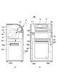
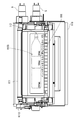
- an empty container collection device 100 as an article collection device is provided with a container loading unit 110 at the upper part of the apparatus main body 100B, An outer door 111 is provided outside the opening of the portion 110.
- the apparatus main body 100B is provided with a display operation unit 3 and a transmission / reception unit 4 (communication unit) on the front side near the upper part of the outer door 111.
- a luggage hook 100f is provided on the front side of the apparatus main body 100B.
- a passage communicating with the container accommodation portion 140 is provided below the container insertion portion 110, and an inner door 112 is provided in the passage 71 from the placement portion 116 of the container insertion portion 110 to the container accommodation portion 140. ing.
- the empty container collection device 100 is provided with a volume reducing part 120 (volume reducing mechanism) between the inner door 112 and the container housing part 140.
- the volume reducing unit 120 crushes and reduces the volume of the empty container A from the container loading unit 110, and outputs the volume-reduced container RA to the lower container storage unit 140.
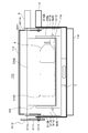
- the apparatus main body 100B of the empty container collection apparatus 100 has a drawer 100C on which the container accommodating section 140 is placed, and a drawer handle 100e and a key hole 100r are provided on the front side. It is configured to be able to be inserted and locked into the hole 100r.
- a light-transmitting portion 100A (light-transmitting window) is provided on the front side of the apparatus main body 100B, more specifically, on the front side of the drawer 100C, and an empty container accommodated in the container accommodating portion 140 from the outside. Is configured to be visible.
- a moving handle 100g used at the time of conveyance is provided on the side surface of the apparatus main body 100B.
- the apparatus main body 100B includes a cap insertion portion 108 on the front side, a cap passage 72 is provided downward from the cap insertion portion 108 in the apparatus main body, and the cap inserted into the cap insertion portion 108 is a cap. It is configured to be accommodated in the cap accommodating portion 145 through the use passage 72.
- the cap passage 72 may have a mechanism for sorting caps and smaller ones than the caps. Specifically, the cap passage 72 is branched, and the left-handed drinking butt, rainwater, etc. are discharged and accumulated by another route by a mesh-like member at the branching portion, so that only the cap is accommodated in the cap accommodating portion 145. It may be.
- FIG. 2 is a conceptual diagram of the container loading unit of the empty container collection device.
- 3 and 4 are diagrams illustrating an example of an empty container collection device in which the outer door 111 is closed and the inner door 112 is closed.
- 5, 6, and 7 are diagrams illustrating an example of the empty container collection device 100 in which the outer door 111 is in an open state and the inner door 112 is in a closed state.
- 8 and 9 are conceptual diagrams illustrating an example of an empty container collection device in which the outer door 111 is closed and the inner door 112 is open. In FIG. 9, the outer door is not shown.
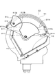
- the container loading unit 110 of the empty container collection device 100 includes a placement unit 116, an outer door 111, an inner door 112, a pedestal 118, a weighing unit 7, an outer door support unit S111, and an inner door support.
- the placement unit 116 is configured to be able to place a collection object or the like.
- the mounting unit 116 is provided with an optical sensor 9 such as a light receiving unit 9a and a light emitting unit 9b, a metal sensor, and the like.
- the weighing unit 7 is provided below the placement unit 116.
- the placement unit 116 has a placement surface that is not horizontal, so that the container accommodation unit 140 side is lower than the article insertion port side (opening side when the outer door 111 is open). Is provided with an inclination. That is, the placement unit 116 is configured to urge the thrown-in article to fall to the container housing unit 140 side (or the volume reducing unit 120 side) due to its own weight. Thereby, there is no need to provide a transport mechanism for sending the article (input) to the container housing section 140, and a small article recovery apparatus can be provided.
- the placement unit 116 has a structure in which a surface treatment is performed on the surface of the placement surface to form a concavo-convex portion, and the charged article is prevented from sticking to the placement unit.
- the article recovery device is a container recovery device, even if the container is wet, the contact area between the surface of the container and the uneven surface of the mounting portion is relatively small, so the surface tension due to wetting is reduced, and the container is easily moves to the accommodating portion 140 side. That is, it is possible to prevent a problem that a wet container does not fall to the container housing part side.
- the outer door 111 is provided outside the placement unit 116.
- the outer door drive unit 5 drives the outer door 111 to be openable and closable.
- the inner door 112 is provided in the passage 71 between the placement unit 116 and the volume reduction unit 120.
- the inner door drive unit 6 drives the inner door 112 to be openable and closable.
- the inner door 112 is provided with a guide portion 112 ⁇ / b> D that guides the placement state of the empty container.
- the guide portion 112D is provided at a position where it is exposed and visible from the apparatus main body portion.
- the guidance unit 112D is guided and displayed as information so that an article (an empty container such as a PET bottle) is placed in a prescribed direction and a prescribed position (for example, 350 ml, 500 ml, 2000 ml, etc.).
- the guide portion 112D may be a concave portion, a convex portion, a sticker, an LED display portion, an LCD, or the like provided on the surface of the inner door 112.
- the article collection device may include a determination unit for determining whether or not the article is correctly placed at the placement position indicated by the guide unit 112D by a detection sensor such as an imaging unit.
- a detection unit such as an imaging process or an optical sensor, notification or the like can be performed.
- the empty container collection device 100 includes a pedestal 118, and the pedestal 118 includes an outer door 111 and outer door support portions S 118 and S 111 that support the outer door driving unit 5. More specifically, the outer door drive unit 5 and the rotation shaft C111 are provided at the upper ends of the two outer door support portions S118, and the fan-shaped outer door support portion S111 is rotatably provided on the rotation shaft C111.
- the outer door 111 is supported by a fan-shaped outer door support portion S111.
- One of the two rotating shafts C111 is connected to the rotating shaft of the motor of the outer door drive unit 5.
- the fan-shaped outer door support portion S111 is provided with a hole portion S111h through which the rotation shaft C112 of the inner door 112 passes.
- the measuring unit 7 is disposed between the pedestal 118 and the mounting unit 116 and supports the mounting unit 116.
- the inner door 112 is configured to guide the empty container placed on the placement unit 116 to the volume reduction unit 120 in the open state.
- the inner door driving unit 6 and the inner door 112 are supported by the inner door support portion S112 arranged on the weighing unit 7 and extending from between the weighing unit 7 and the placing unit 116.
- the inner door drive unit 6 is provided with a rotation axis C112 of the inner door 112, and the inner door 112 is provided on the rotation axis C112.
- the inner door support portion S112 has a hole portion S112h through which the rotation shaft C111 passes.
- the outer door driving unit 5 and the outer door 111 are supported by the outer door support portion S111 of the pedestal 118, and the placement unit 116 is provided above the weighing unit 7 disposed on the pedestal 118.
- the unit 7 can measure the mass of the collection object placed on the placement unit 116 with high accuracy. Specifically, since the outer door 111 and the outer door driving unit 5 are not supported on the measuring unit 7, the measuring unit 7 is affected by vibrations of the outer door 111 and the outer door driving unit 5. The structure is difficult to receive, and the mass of the object to be collected on the placement unit 116 can be measured with high accuracy.
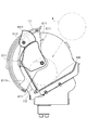
- the outer door 111 of the empty container collection device 100 as the article collection device according to the embodiment of the present invention can move between an open position where the placement unit 116 is exposed and a closed position where the placement unit 116 is covered.
- the outer door 111 is configured to be movable from the open position to the closed position toward the placement unit 116. That is, since the outer door 111 is configured to move and close toward the placement unit 116 from the open state, for example, a user's hand or arm is sandwiched between the outer door 111 and the placement unit 116.
- the control unit detects the change, so that it is easy for the user's hand, arm, foreign object, etc. to be sandwiched between the outer door 111 and the placement unit 116. Can be detected.
- the outer door 111 is provided with the 1st restriction
- the inner door 112 includes a second restricting portion K112 that restricts movement of the outer door 111.
- the first restricting portion K111 and the second restricting portion K112 have a mechanism for restricting both the outer door 111 and the inner door 112 from being opened. That is, since the empty container collection device 100 has the first restricting portion K111 provided on the outer door 111 and the second restricting portion K112 provided on the inner door 112, the outer container recovery device 100 has a mechanically simple structure and has an outer structure. Depending on the open / close states of the door 111 and the inner door 112, the opening / closing operation of each door can be restricted.
- the first restricting portion K111 of the empty container collection device 100 as the article collection device is configured to respond to the movement of the outer door 111.
- the second restricting portion K112 is configured to respond to the movement of the inner door 112.
- the empty container collection device 100 is configured such that when the outer door 111 is in the open state, the first restricting portion K111 restricts the movement of the inner door 112, and when the inner door 112 is in the open state, Two limiting portions K112 are configured to limit the movement of the outer door 111.
- the empty container collection device 100 when the outer door 111 is in the open state, the empty container collection device 100 is configured to restrict the inner door 112 from being opened while being closed.
- the inner door 112 when the outer door 111 is in the open state and the thrown-in object is placed on the placement unit 116, the inner door 112 is in the closed state, not in the open state, but placed on the placement unit 116. Regardless of whether the collected object is a collection object or a non-recovery object, the container is not accommodated in the container accommodation unit 140 in the apparatus main body 100B. That is, in this state, an article (a collection object or a non-collection object) is in contact with the inner door 112, and the inner door 112 has a structure that also serves as a part of a placement portion.
- the first restriction unit K111 and the second restriction unit K112 are configured such that the movement paths overlap each other.
- recovery apparatus 100 when one side restrict
- the first restricting portion K111 is formed in a substantially fan shape.
- the first restricting portion K111 has a convex arc shape portion K111a and a concave shape portion K111b.
- the second restricting portion K112 is formed in a substantially fan shape.
- the second limiting portion K112 has a convex arc shape portion K112a and a concave shape portion K112b.
- the first restrictor K111 restricts the movement of the second restrictor K112
- the first The convex arc-shaped portion K111a of the limiting portion K111 and the concave-shaped portion K112b of the second limiting portion K112 are adjacent to each other with a slight gap therebetween. That is, in the embodiment of the present invention, as described above, when the outer door 111 is in the open state, the inner door 112 is in the closed state, and the movement of the second restricting portion K112 is restricted by the first restricting portion K111. Therefore, the inner door 112 is maintained in the closed state and is not in the open state.
- the second restriction portion K112 causes the first restriction portion K111. Therefore, the outer door 111 is maintained in a closed state and does not enter an open state.
- recovery apparatus 100 may have a prohibition means which prohibits the movement of one or both of the 1st restriction
- the prohibiting unit includes, for example, a solenoid.
- a metal movable pin (plunger) is disposed in the coil, and the solenoid is disposed at a position where the movable pin (plunger) protrudes from the coil end portion by the urging portion when the coil is not energized.
- the structure is such that the movable pin moves into the coil when the coil is energized.
- a movable pin (plunger) of the solenoid for the outer door engages with a hole provided in the first restricting portion K111.
- the movable pin is engaged with the hole portion and the movement is not prohibited.
- control is performed by the control unit so that the movable pin is disengaged. That is, the prohibiting means can prohibit the movement of the first restricting portion K111 from the closed state to the open state with a simple structure.
- a prohibiting means capable of prohibiting the movement of the inner door 112 from the closed state to the opened state
- a movable pin (plunger) of the solenoid for the inner door engages with a hole provided in the second restricting portion K112.
- the movable pin is engaged with the hole, and the movement is not prohibited.
- control is performed by the control unit so that the movable pin is disengaged. That is, the prohibiting means can prohibit the movement of the second restricting portion K112 from the closed state to the open state with a simple structure.
- recovery apparatus which concerns on embodiment of this invention has standby part AA where the outer door 111 waits in a closed position, as shown in FIG.5, FIG.9.
- the standby portion AA is provided at a position where the outer door 111 does not touch the placement portion 116, and functions as a stopper for the outer door 111.
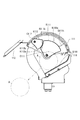
- FIG. 10 is a conceptual side view showing an example of the volume reducing unit of the empty container collection device as the article collection device according to the embodiment of the present invention.
- FIG. 11 is a conceptual plan view showing an example of the volume reducing portion of the empty container collection device.
- the volume reducing unit 120 has a structure in which a pair of rotating shafts 811 and 911 are rotatably supported by two substantially plate-shaped support members.
- a feeding mechanism 50 is provided on the upper portion of the volume reducing portion 120, and a rotating shaft 51 of the feeding mechanism 50 is rotatably supported by the substantially plate-shaped support member.
- the feed mechanism 50 has a plurality of blade portions 52 (made of metal or resin, etc.) as paddles on a rotating shaft 51.
- the rotating shaft 51 rotates, whereby the blade portion 52 rotates around the rotating shaft 51, and guides the empty container A to the volume reducing portion 120.
- a plate-shaped regulating member 61 and a regulating member 62 are provided on the upper portion of the volume reducing portion 120 so as to be inclined in opposite directions so as to guide the empty container A to the center of the volume reducing portion 120. The movement of the empty container A to other locations is restricted.
- the rotary shafts 811, 911, 51 are arranged in parallel with each other with a predetermined interval.
- the compression rollers 81 and 91 having blade surfaces 81k or blade surfaces 91k on both side surfaces in the axial direction, and the compression rollers 81 and 91 having a diameter smaller than that of the compression rollers 81 and 91.
- the spacers s slightly thicker than the thickness are alternately arranged in parallel along the axial direction.
- the outer peripheral portion of the compression roller provided on one rotation shaft is disposed between the compression rollers provided on the other rotation shaft, and is provided between the compression rollers provided on the other rotation shaft.
- the spacer s is disposed at a position separated by a predetermined distance LP.
- the distance LP between the spacer s provided on the rotating shaft 811 and the compression roller 91 provided on the rotating shaft 911 facing the spacer s is the maximum outer diameter LAg of the trunk portion Ag of the empty container A. Is set smaller than.
- a gear 811 m is provided at one end of the rotating shaft 811, and is configured to mesh with a gear 911 m provided at one end of the rotating shaft 911.
- the rotary shafts 811, 911, 51 are rotationally driven by a drive motor (not shown). At the time of driving, the rotating shaft 811 and the rotating shaft 911 rotate in opposite directions, and the empty container A put in the center is compressed by the compression rollers 81 and 91, and the reduced empty container is output downward. .
- the peeling units 31 and 32 are configured to peel the containers reduced by the compression rollers 81 and 91 of the volume reduction unit 120 from the compression rollers 81 and 91.
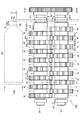
- the length LAb (neck length) of the neck Ab of the empty container A such as a plastic bottle is the length from the tip Ac on the opening Ah side to the neck ring or the base of the neck. is there.
- the empty container A made of resin, such as a plastic bottle, is formed thicker than the thickness of the other part, specifically, the shoulder part, the trunk part Ag, etc., compared to the thickness of the neck part Ab.
- the recycler may consider it unrecyclable.
- the volume-reducing portion 120 has a flat shape in a state larger than the above standard so that the empty container can be recycled with the relatively thick and heavy neck portion Ab not separated from the shoulder portion and the trunk portion Ag. Reduce volume.
- the distance LT between the spacer s provided on the rotating shaft 911 and the spacer ws (s) provided on the rotating shaft 811 is longer than the outer diameter of the neck Ab of the empty container.
- the distance LC from the inner surface of the support member 871 to the compression roller 81 disposed on the side surface of the rotating shaft 811 is configured to be longer than the length LAb of the neck Ab of the empty container A.
- the distance LC is set to be longer than the axial length of the spacer ws (s) disposed on the side surface side of the rotating shaft 811.
- the length (thickness) in the axial direction of the spacer ws (s) is set to about twice as long as the axial length Ls of other spacers.
- the compression roller on the support member 871 side provided on the rotation shaft 811 is separated from the side surface of the support member 871 by a predetermined distance so that the neck portion Ab of the empty container A is not separated from the shoulder portion and the trunk portion Ag. Placed in position. That is, the volume reducing part 120 has a structure that reduces the volume when the neck part Ab of the empty container A is connected to the shoulder part or the trunk part Ag when the container is reduced in volume.
- the axial thickness L1 of the compression rollers 81 and 91 is shorter than the length LAb of the neck Ab of the empty container A.
- the tip portion Ac formed with the opening Ah of the empty container A is in detail on the substantially plate-shaped support member 871 side. Even when arranged so as to be positioned, the neck portion Ab of the empty container A is not separated from the shoulder portion and the trunk portion Ag when the volume of the container is reduced.
- the article collection device includes a control unit 1 (CPU), a storage unit 2, a display operation unit 3, a transmission / reception unit 4, an outer door drive unit 5, and an inner door drive unit. 6, the measurement part 7, the metal sensor 8, the optical sensor 9, the door position sensor 10, the door lock part 11, the volume reduction drive part 15 grade
- Each component is electrically connected by a signal line or the like.
- Control unit 1 comprehensively controls each component of the article collection device (empty container collection device 100).
- the storage unit 2 is a storage device such as a RAM or a ROM.
- the storage unit 2 stores a control program and the like.
- the storage unit 2 stores the characteristics of the empty container of the collection object.
- the characteristics of the empty container are, for example, a range of the container mass and whether or not the resin material is used.
- the display operation unit 3 performs a predetermined display under the control of the control unit 1. In addition, the display operation unit 3 outputs a signal corresponding to the operation of the user or the like to the control unit 1.
- the display operation unit 3 is, for example, a touch panel display device.
- the transmission / reception unit 4 is a transmission / reception device that communicates with a non-contact IC card, an IC tag, or the like, and performs predetermined communication under the control of the control unit 1. Further, the transmission / reception unit 4 performs predetermined communication with another terminal device (computer) through a wireless communication path or a wired communication path under the control of the control unit 1.
- the outer door driving unit 5 is a motor or the like for opening and closing the outer door 111, and is driven and controlled by the control from the control unit 1.
- the inner door drive unit 6 is a motor or the like for opening and closing the inner door 112, and the inner door is driven and controlled by the control from the control unit 1 in an open state or a closed state.
- the weighing unit 7 measures the mass of the empty container placed on the placement unit 116 of the container loading unit 110 or the non-recoverable object.
- the weighing unit 7 is a weighing device such as a load cell. Further, the measuring unit 7 is used as a sensor for determining whether or not it can be recovered by detecting a leftover in the container placed on the placement unit 116 of the container loading unit 110.
- the measuring unit 7 is also configured to be able to specify the total weight stored in the container storage unit 140 by integrating the weight values of the containers determined to be recoverable. With this function, there is no need to provide a weighing part in the container housing part 140, a large capacity container housing part 140 can be secured, and the weighing part 7 itself can be made small. Since the object to be weighed is relatively small, there is no need to provide a large weighing unit 7.
- the metal sensor 8 detects whether an object placed on the placement unit 116 of the container loading unit 110 is a metal or a non-metal. In the present embodiment, when the control unit 1 detects that an object placed on the placement unit 116 is metal by the metal sensor 8, the object placed on the placement unit 116 is a non-recoverable object. Determine that there is.
- the optical sensor 9 includes a light receiving unit 9 a that receives light from the light emitting unit 9 b provided in the container loading unit 110.
- the optical sensor 9 includes, for example, a polarizing plate, and is configured to receive light through the polarizing plate. By detecting polarized light transmitted through a light-transmitting empty container such as a PET bottle, the optical sensor 9 An empty container can be detected.
- the control unit 1 detects light received through the translucent empty container placed on the placement unit of the container insertion unit by the optical sensor 9, and based on a detection signal from the optical sensor 9. Then, it is determined whether or not it is an empty container to be collected.
- the article collection device is provided with the above-described sensors for determining whether collection is necessary or not around the placement unit.
- a conventional collection device an article is taken into the device, it is determined whether or not it is a collection target, non-objects are discharged from a discharge port different from the input port, and a determination unit is provided in the device. Therefore, it is necessary to provide a discharge port.
- the article recovery apparatus according to the embodiment of the present invention has a configuration in which there is no need to take in a recovery object into the apparatus because sensors for determining whether or not recovery is necessary are provided in a mounting portion corresponding to an input port of the apparatus. It has become. Therefore, there is no need to provide a discharge port, and a small article recovery device can be provided.
- the door position sensor 10 detects the position of the outer door 111 and the position of the inner door 112, and outputs a signal related to the position of the outer door 111 and the position of the inner door 112 to the control unit 1.
- the control unit 1 controls the open / closed state of the outer door 111 and the inner door 112 based on the signal.
- the door lock unit 11 has a locking device such as a solenoid, for example, and locks the movement of the outer door 111 and the inner door 112 as necessary under the control of the control unit 1.
- the control unit 1 includes a first drive control unit 101, a second drive control unit 102, a third drive control unit 103, a fourth drive control unit 104, a notification processing unit 105, the determination unit described above, and the like.
- the control part 1 implement
- the first drive control unit 101 controls the outer door 111 to be opened by the outer door drive unit 5 during container collection.
- the second drive control unit 102 sets the outer door 111 in the closed state and the inner door 112 in the open state by the outer door driving unit 5 and the inner door driving unit 6 when the collection object is placed on the placement unit 116. Then, the container storage unit 140 performs control to collect the container.
- the third drive control unit 103 detects the inner door 112 by the outer door driving unit 5 and the inner door driving unit 6 when the detection by the detection unit is a non-recovery target and the non-recovery target is not excluded for a predetermined time or longer.
- the closed state is maintained and the outer door 111 is controlled to be closed.
- the fourth drive control unit 104 closes from the open position of the outer door 111 when the measuring unit 7 detects a change in the measured value. Control to stop moving to the position. That is, when the outer door 111 moves from the open position to the closed position, the control unit 1 stops the movement of the outer door 111 from the open position to the closed position when detecting a change in the measurement value by the measuring unit 7. By performing the control, it is possible to prevent a user's hand, arm, foreign object, or the like from being sandwiched between the outer door 111 and the placement unit 116, reducing the load on the outer door driving unit 5, Prevention can be performed.
- the notification processing unit 105 When the detection unit detects a non-recoverable object, the notification processing unit 105 performs a notification process so as to exclude the non-recoverable object.
- a notification process for example, a screen display that prompts the display unit of the display operation unit 3 to exclude non-recoverable objects is performed.
- step ST1 the empty container collection device 100 is in a standby state.
- the control unit 1 When receiving a signal from the transmission / reception unit 4 (communication unit) or the display operation unit 3, the control unit 1 performs processing according to the signal. Further, the control unit 1 performs a process of displaying, for example, “Please touch a card (membership card or the like)” on the display unit of the display operation unit 3.
- the card (membership card or the like) is, for example, a contactless IC card for members.
- step ST2 the control unit 1 determines whether or not the outer door opening condition is satisfied.
- the control unit 1 proceeds to the process of step ST3.
- an outer door opening condition for example, when an empty container collection start button is operated by the display operation unit 3 such as a touch panel, the process proceeds to step ST3.
- a membership card for example, a non-contact IC card, a magnetic card, a card on which a barcode or a two-dimensional code is printed, a display device on which a barcode or a two-dimensional code is displayed, a smartphone having a membership card function, A mobile phone can be cited.
- the control unit 1 performs a process of displaying on the display unit of the display operation unit 3, for example, “please load the container”.
- step ST3 the control unit 1 performs an outer door opening process. Specifically, the control unit 1 performs drive control in which the door lock portion of the outer door 111 is in a released state and the outer door driving unit 5 moves the outer door 111 to an open state.
- step ST4 the mass of the article placed on the placement unit 116, material, presence / absence of contents, and the like are detected by various detection processes using the weighing unit 7, the metal sensor 8, the optical sensor 9, and the like. A signal indicating the detected result is output.
- step ST5 the control unit 1 determines whether or not the outer door closing condition is satisfied. Specifically, if it is determined that the object placed on the placement unit 116 is a collection object, the process proceeds to step ST6, and otherwise (in the case of a non-collection object such as a foreign object), step ST51. Proceed to the process. Note that, for example, even when the control unit 1 determines that the article placed on the placement unit 116 is an empty container as a result of the detection process, for example, a predetermined amount of liquid left in the container is left. When the presence is detected, it may be determined that a foreign object is included.
- step ST6 the control unit 1 performs an outer door closing process. Specifically, the control unit 1 drives and controls the outer door driving unit 5 so as to close the outer door.
- step ST7 the control unit 1 determines whether or not a change in the measurement value by the measurement unit 7 is detected. If a change in the measurement value is detected, the process proceeds to step ST8. The detection process in step ST7 is continued until the value change is settled.
- step ST8 the control unit 1 determines whether or not the inner door opening condition is satisfied. As a result of the determination, if the inner door opening condition is not satisfied, the process proceeds to step ST13, and if the inner door opening condition is satisfied, The process proceeds to step ST9.
- the inner door opening condition is, for example, that an object placed on the placement unit 116 is a collection target object.
- step ST9 the control unit 1 performs an inner door opening process. Specifically, the control unit 1 performs drive control by the inner door driving unit 6 so as to open the inner door 112.
- step ST ⁇ b> 9 the control unit 1 performs a process of displaying on the display unit of the display operation unit 3, for example, “Recycling container XX book” or the like.
- the control unit 1 performs a process of counting up the number of containers and displaying it on the display unit. Further, when the charging is not continuous, the control unit performs processing for displaying on one container and the display unit.
- step ST10 the control unit 1 performs an inner door closing process. Specifically, the control unit 1 performs drive control by the inner door driving unit 6 so that the inner door 112 is closed. The inner door 112 is in a closed state, and the placement unit and the volume reduction unit are separated (separated state). Then, the process proceeds to step ST11.
- step ST11 the control unit 1 performs an outer door opening process. Specifically, the control unit 1 performs drive control by the outer door driving unit 5 so as to open the outer door 111.
- the outer door 111 is in an open state, and the next container can be charged.
- step ST11 for example, the control unit 1 performs a process of displaying on the display unit of the display operation unit 3 such as “Please insert the next container, please touch the screen if there is nothing”. As will be described later, when an operator (such as a user) touches the screen of the display operation unit 3, the end is declared.
- step ST12 the control unit 1 performs a volume reduction process. Specifically, the control unit 1 performs a process of reducing the volume of the empty container A by the volume reducing unit 120. Note that the volume reduction process in step ST12 may not be performed. Moreover, you may select reducing the volume of a container as needed and not reducing the volume.
- step ST13 the control unit 1 determines whether or not an article has been newly added to the placement unit based on a signal from each sensor, and as a result of the determination, the control unit 1 uses any sensor (detection unit) of the placement unit. Is detected, the process proceeds to step ST4, and if no article is detected, the process proceeds to step ST14.
- step ST4 it is possible to perform continuous container loading processing. Specifically, since a new container can be put into the mounting unit while the volume reducing unit is reducing the volume of the empty container, detection by the sensor (detection unit) of the mounting unit Processing and volume reduction processing by the volume reduction unit can be performed in parallel. That is, the article recovery apparatus can efficiently reduce the volume of the empty container.
- the inner door 112 is closed during the volume reduction process, and the placement unit and the volume reduction unit 120 are separated (separated state). Therefore, even if debris such as a container is scattered by the volume reduction process by the volume reducing unit, the debris does not reach the placement unit.
- step ST14 the control unit 1 determines whether or not an end operation has been detected. If the end operation is detected, the control unit 1 proceeds to step ST1. Otherwise, the control unit 1 proceeds to step ST15. Specifically, the control unit 1 performs a process of displaying, for example, “Please insert the next container, please touch the screen if there is no” on the display unit of the display operation unit 3, and touch the screen. When the end of operation is detected, the process proceeds to step ST1.
- step ST15 the control unit 1 determines whether or not the volume reduction processing of the container by the volume reduction unit 120 is completed. If completed, the control unit 1 proceeds to the process of step ST1, and if not completed, the process of step ST13 is performed. Proceed to Specifically, in step ST15, the control unit 1 starts counting from the outer door open state of ST11, and when a predetermined time has elapsed, determines that there is no next container, and automatically waits as described above. The process proceeds to step ST1.
- step ST51 the control unit 1 determines whether or not the outer door closing condition is satisfied in step ST5, and when it is determined that the object placed on the placement unit 116 is a non-recoverable object, It is determined whether or not a time, for example, about 30 seconds to 1 minute has elapsed, and if the result of determination is that a predetermined time has elapsed, the process proceeds to step ST52, and if the predetermined time has not elapsed, The standby state is maintained until a predetermined time has elapsed.
- a time for example, about 30 seconds to 1 minute
- step ST52 and step ST53 the control unit 1 performs an outer door closing process for closing the outer door 111 while maintaining the closed state of the inner door 112. Specifically, the outer door driving unit 5 is driven and controlled so that the control unit 1 and the outer door 111 are closed.
- step ST54 the control unit 1 performs a notification process. Specifically, when the non-recoverable object is placed on the placement unit 116 of the container loading unit 110 and the outer door 111 is closed, the control unit 1 reduces the volume of the non-recoverable object. A process for notifying that it is in a state where it remains in the input part and is not recovered, or a process for notifying that the non-recoverable object is removed from the placement part 116 is performed. As a notification process, the process displayed on the display part of the display operation part 3, the process which sounds a predetermined notification sound, and the process which light-emits light emitting elements, such as LED, are performed. Then, the process proceeds to step ST1.
- the notification may be performed to an external terminal device (not shown).
- the external terminal device is, for example, a POS terminal installed in a store, a portable terminal device carried by a store clerk or a system administrator, a host server, or the like.
- the control unit 1 may perform the above notification (pop-up screen display, lamp lighting, sound output, etc.) to the external terminal device via the wireless or wired communication path by the transmission / reception unit 4. Further, the control unit 1 may output an error so that it can be directly notified by each terminal device, or may output an error to a higher-level server and the POS terminal or the like may perform the notification via the server.
- the control unit 1 may similarly notify other error information (full detection, consumable parts replacement sign, other failure errors, etc.).
- the case where the container collection person is specified and the case where the container collection person is not specified will be described in detail.
- the store clerk or the like who receives the notification transmits / receives an IC card (identification information for the manager is stored in the storage unit of the IC card) with the identification information for the manager.
- the control unit When the control unit is held over or touched (or brought close to) the unit 4, the control unit confirms that the authentication process is correctly performed for the administrator, and then performs control to open the outer door 111.
- the outer door 111 is opened and a store clerk can remove non-collected items.
- the control unit 1 You may perform the process which makes the outer door 111 an open state regardless of whether it is an administrator. As a result, a user who wants to use the article recovery apparatus can have the non-recoverable object removed. That is, it is possible to prevent a chance loss that the article collection device cannot be used until a store clerk or the like comes and removes the non-collection object.
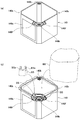
- FIG. 14A is a perspective view showing an example of a container housing portion
- FIG. 14B is a view showing an example of a container housing portion equipped with a container housing bag and a cap housing bag. .
- the container housing part 140 detachably provided at the lower part of the apparatus main body part 100B of the empty container recovery apparatus 100 is a substantially rectangular parallelepiped having an opening at the top and a bottom at the bottom.
- the container is provided with a translucent part 140a or a semi-translucent part on the front side, and is configured so that the inside of the container accommodating part 140 can be easily seen from the outside.
- a large container housing bag is detachably provided in the container housing section 140 having an opening at the top.
- the container accommodating part 140 which has a substantially rectangular opening part in the upper part is provided with the insertion port 140b for fixing the container accommodating bag BB near the upper end of the side surface.
- a slit-like insertion port 140b is formed at the center of the oval elastic member.
- the container housing bag BB When the container housing bag BB is attached to the container housing portion 140, the container housing bag BB is housed in the center of the container housing portion 140, and the upper end of the container housing bag BB is folded outward to the insertion port 140b. Plug in. That is, by inserting the slit into the slit-like insertion port 140b of the elastic member, the bag is locked to the slit, so that the container housing bag BB is fixed to the container housing portion 140.
- the container housing bag BB After collecting a plurality of containers in the container housing bag BB, when removing the container housing bag BB from the container housing portion 140, the container housing bag BB is pulled from the insertion port 140b with a predetermined force or more. Thus, the bag is disengaged and the bag can be easily removed.
- a cap housing portion is provided in a part of the container housing portion 140.
- the cap housing bag BS is arranged at one corner of the container housing section 140.
- the cap housing bag BS preferably includes, for example, two handle portions.
- the container housing part 140 is provided with a locking part such as a hook near the upper part of the side surface of the corner part.
- the container housing part 140 locks the handle part of the cap housing bag BS to the engaging part, and arranges the opening part of the bag near the outlet of the cap passage so that the cap can be easily structured. Can be easily accommodated.
- the cap housing portion has a structure supported in the container housing portion 140. Also, the handle portion BSa of the cap housing bag BS as the cap housing portion is locked to a locking portion such as a hook 140f near the upper portion of the outer surface of the container housing portion 140, thereby realizing the above configuration easily. can do. Moreover, since it has the structure where the cap accommodating part was provided in the container accommodating part 140, space saving can be implement
- FIG. 15 is a perspective view showing another example of the container loading unit of the empty container collection device according to the embodiment of the present invention.
- the container loading part 110B in the empty container collection device, has a manual drawer structure, and a placement part 116B for placing the empty container is provided in the drawn part.
- the control unit of the empty container collection device determines whether or not it is a collection target based on the signals from the various sensors (such as the weighing unit, the optical sensor, and the metal sensor) described above.
- the manual container loading unit 110B can be closed, and when the part pulled out by the user is closed, the inner door 112B is opened and is placed in the apparatus main body.
- the manual container loading unit 110B is locked by a locking mechanism such as a solenoid and is not closed.
- a locking mechanism such as a solenoid
- the outer door is configured to be closed by rotating from the top to the bottom.
- the closing direction and the moving method are not limited, and the closing direction is, for example, the bottom From top to bottom, from right to left, from left to right, from the front to the back, the moving method may be rotation, parallel movement, folding, separable lid or door.
- the inner door is the same as the outer door. Further, at least the opening and closing of the outer door is not limited to drive control, and may be a manual type, for example.
- the empty container collection apparatus 100 as the article collection apparatus includes the apparatus main body 100B including the accommodation section (container accommodation section 140) for accommodating articles, and the container input section 110.
- the container loading unit 110 includes a placement unit 116 on which an article can be placed, an outer door 111 provided outside the placement unit 116, and a storage unit (container storage unit) in the apparatus main body 100B from the placement unit 116. 140) and an inner door 112 provided in a passage 71 leading to 140).
- the empty container collection device 100 as an article collection device includes an outer door drive unit 5 that drives the outer door 111 to open and close, and an inner door drive unit 6 that drives the inner door 112 to open and close.
- recovery apparatus 100 is provided in a mounting part, and has a detection means (The measurement part 7, the optical sensor 9, the metal sensor 8, etc.) which detects the articles
- recovery apparatus 100 has the control part 1,
- the control part 1 has a discrimination
- An apparatus can be provided.
- the detection means of the empty container collection device 100 as the article collection device according to the embodiment of the present invention is provided in the placement unit 116 of the container loading unit 110 and the mass of the article placed on the placement unit 116. It has a mass detection part (measuring part 7) which detects.
- the discriminating unit of the control unit 1 discriminates whether or not the object is a collection target based on the mass of the article placed on the placing unit 116 detected by the mass detecting unit (the weighing unit 7). Specifically, for example, when the mass of the article placed on the placement unit 116 is within a range specified in advance with respect to the mass of the empty container of the collection target, the determination unit sets the placement unit 116 to the placement unit 116.
- the placed object is a collection object
- the outer door is closed, the inner door is opened, the empty container to be collected is accommodated in the main body of the device, and if it is outside the range, the non-collection object
- the inner door is closed and the inner door is kept closed so as not to be collected into the apparatus main body, and the outer door is kept open. That is, based on the mass of the article placed on the placement unit 116, when the object placed on the placement unit 116 is a non-recoverable object, the object is not accommodated in the apparatus main body 100B and is to be collected. It is possible to provide a small empty container collection device with a simple structure that can accommodate only an object in the container accommodating portion 140 in the apparatus main body 100B.
- control unit 1 (the first drive control unit 101, the second drive control unit 102, the third drive control unit 103, etc.) of the empty container collection device 100 as the article collection device according to the embodiment of the present invention is a discrimination unit.
- the inner door drive unit 6 controls the driving so as to maintain the closed state of the inner door 112.
- the determination unit determines that the object is a collection object, the inner door 112 is moved. It has a drive control part which carries out drive control by the inner door drive part 6 so that it may be in an open state.
- the input article when the input article is a non-recoverable object, a simple structure that can store only the recovery object in the container housing part 140 in the apparatus body 100B without being housed in the apparatus body 100B. Thus, a small empty container recovery device can be provided.
- an empty container collection device 100 as an article collection device includes an article input unit (container input unit 110) including a placement unit 116 for placing an article, and an article input unit ( An outer door 111 provided at the opening of the container loading section 110) so as to be freely opened and closed, an outer door driving section 5 that drives the outer door 111 to open or close the outer door 111, and a container loading section.
- the control unit 1 as the drive control unit performs control for opening the outer door 111 when the article is collected.
- control unit 1 (second drive control unit or the like) closes the outer door 111 when the determination unit determines that the collection target is placed on the placement unit based on the detection result of the detection unit.
- the inside door 112 is opened, and the container is controlled to collect the article to be collected.
- the discrimination unit determines that the non-collection object is placed on the placement unit 116, and the non-collection object When an object is not excluded for a predetermined time or more, the drive control unit performs control for maintaining the closed state of the inner door 112 and closing the outer door 111.
- the outer door 111 is closed and the inner door 112 is closed during the initial standby, and the outer door 111 is opened while the inner door 112 is closed at the start of collection, so that non-recoverable objects such as foreign matter are put into the container.
- a predetermined time or more for example, 1 minute or more
- the outer door 111 is closed. It is possible to provide an empty container recovery device that prevents further non-recoverable objects (foreign substances) from being mixed.
- the outer door is closed after a predetermined time has passed. Therefore, it is possible to provide an empty container collection device with less intrusion of rainwater or the like.
- control unit 1 of the empty container collection device 100 as the article collection device determines that the non-collection object is placed on the placement unit when the discrimination unit determines that the non-collection target is placed on the placement unit.
- a notification unit (notification processing unit) that performs notification so as to exclude an object from the container charging unit is provided.
- the control unit 1 performs a notification process for displaying on the display operation unit 3 that a non-recoverable object has been detected.
- the control part 1 performs the alerting
- the control unit 1 of the empty container collection device 100 as the article collection device when the discrimination unit determines that the non-recovery object is placed on the placement unit, the non-recovery target A notification unit (in this embodiment, a notification processing unit 105 of the control unit 1 and a display operation unit 3) that performs notification so as to exclude an object from the placement unit is included. Specifically, when the non-recoverable object is detected by the detection unit, the control unit 1 displays on the display unit of the display operation unit 3 so as to exclude the non-recoverable object from the container loading unit.
- the notification unit of the empty container collection device 100 performs the above notification to the external terminal device. That is, for example, the notification can be performed by an external terminal device in the store. Further, the notification can be performed by a host server as an external terminal device.
- volume reduction part volume reduction mechanism which reduces an empty container
- the empty container of the input recovery object may be recovered as it is.
- the empty container collection device collects empty containers such as PET bottles, but may be configured to collect aluminum cans, steel cans, etc., and collects PET bottles, aluminum cans, and steel cans. A combined device may be used.
Abstract
Provided is a compact article recovery device which has a simple structure, determines whether an introduced object is an object to be recovered, without taking the object into a device main body, does not accommodate, in the device main body, objects which are not the object to be recovered, and only accommodates the object to be recovered in the device main body. This article recovery device (100) is provided with: a device main body (100B) provided with an accommodation part (140) for accommodating articles; a placement part (116) in which the articles can be placed; an outer door (111) provided to the outside of the placement part; an inner door (112) provided to a passage (71) which passes from the placement part to the accommodation part in the device main body; an inner door drive unit (6) for driving the opening and closing of the inner door; detection means (7, 8, 9) which are provided to the placement part, and which detect an article placed in the placement part; and a control unit (1). The control unit is provided with a determination unit for determining whether the article is the object to be recovered, on the basis of detection results from the detection means.
Description
本発明は、物品回収装置に関する。
The present invention relates to an article collection apparatus.
空容器を回収する空容器回収装置が知られている(例えば、特許文献1参照)。
An empty container recovery device that recovers an empty container is known (see, for example, Patent Document 1).
しかしながら、コンビニエンスストア等の小型店舗などに、空容器回収装置などの物品回収装置を設置する場合、設置場所が狭いため、小型化が望まれている。
However, when an article collection device such as an empty container collection device is installed in a small store such as a convenience store, it is desired to reduce the size because the installation place is small.
ところで、従来の空容器回収装置は、投入口から投入された物をベルトコンベア等で装置本体部内に取り込み、装置本体部内で回収対象物であるか否かを光センサや金属センサなどを用いて判別し、それが回収対象物である場合に装置内の収容部に収容し、それが非回収対象物である場合、装置本体部内を通って外部へ排出する構造であったり、ベルトコンベアなどで排出方向に搬送して投入口から装置外部へ排出する構造であり、複雑な構造で大型の装置であった。
By the way, the conventional empty container collection device takes in the material thrown in from the loading port into the device main body using a belt conveyor or the like, and uses an optical sensor, a metal sensor, or the like to determine whether or not it is a collection object in the device main body. When it is an object to be collected, it is stored in a storage unit in the apparatus, and when it is a non-recoverable object, it is structured to be discharged to the outside through the apparatus main body part or by a belt conveyor or the like. The structure is such that it is conveyed in the discharge direction and discharged from the input port to the outside of the apparatus, and it is a large apparatus with a complicated structure.
また、容器投入部に、外扉と内扉を設け、回収対象物以外の異物(非回収対象物)が容器投入部に投入された場合、その異物を回収せずに、外扉を開状態で、内扉を閉状態のままとする空容器回収装置では、異物を長時間放置すると、外扉が開状態なので、さらなる異物の投入、雨水などの流入などにより、故障やトラブルの原因となる虞がある。
In addition, an outer door and an inner door are provided in the container loading part. When foreign matter other than the collection target (non-recovery target) is thrown into the container loading part, the outer door is opened without collecting the foreign matter. With an empty container collection device that keeps the inner door closed, if the foreign object is left for a long time, the outer door will be open, which may cause trouble or trouble due to the introduction of additional foreign material or the inflow of rainwater. There is a fear.
本発明の物品回収装置は、少なくとも以下の構成を具備するものである。
物品を収容する収容部を備える装置本体部と、
物品を載置可能な載置部と、
前記載置部の外側に設けられた外扉と、
前記載置部から装置本体部内の容器収容部へ通じる通路に設けられた内扉と、
前記内扉を開閉駆動する内扉駆動部と、
前記載置部に設けられ、前記載置部に載置された物品を検知する検知手段と、
制御部とを有し、
前記制御部は、前記検知手段による検知結果に基づいて、回収対象物であるか否かを判別する判別部を有することを特徴とする。 The article recovery apparatus of the present invention comprises at least the following configuration.
An apparatus main body provided with a storage section for storing articles;
A placement section on which an article can be placed;
An outer door provided outside the mounting portion,
An inner door provided in a passage leading from the placement unit to the container housing unit in the apparatus main body,
An inner door drive unit for opening and closing the inner door;
A detecting unit provided in the mounting unit and detecting an article mounted on the mounting unit;
A control unit,
The control unit includes a determination unit that determines whether the object is a collection target based on a detection result of the detection unit.
本発明によれば、投入された物を装置本体部内に取り込むことなく、回収対象物であるか否かを判別し、その物が非回収対象物である場合に、装置本体部内に収容せず、回収対象物のみ装置本体部内の収容部に収容することができる、簡単な構造の物品回収装置を提供することができる。また、小型の物品回収装置を提供することができる。
また、本発明によれば、異物などの非回収対象物が容器投入部に投入された場合、所定時間経過後、外扉が閉状態とすることで、さらなる異物の混入を防止することができる物品回収装置を提供することができる。また、雨水などの流入による故障やトラブルを防止する物品回収装置を提供することができる。 According to the present invention, it is determined whether or not a thrown object is a recovery object without taking it into the apparatus main body, and if the object is a non-recoverable object, it is not accommodated in the apparatus main body. In addition, it is possible to provide an article recovery apparatus having a simple structure in which only the recovery object can be stored in the storage section in the apparatus main body. In addition, a small article collection device can be provided.
In addition, according to the present invention, when a non-recoverable object such as a foreign object is introduced into the container loading unit, the outer door is closed after a predetermined time has elapsed, thereby preventing further contamination of the foreign object. An article collection apparatus can be provided. In addition, it is possible to provide an article recovery apparatus that prevents troubles and troubles due to inflow of rainwater and the like.
以下、本発明の実施形態を、図面を参照しながら説明する。本発明の実施形態は図示の内容を含むが、これのみに限定されるものではない。尚、以後の各図の説明で、既に説明した部位と共通する部分は同一符号を付して重複説明を一部省略する。
なお、本発明の実施形態に係る物品回収装置として、例えば、容器回収装置を説明する。 Embodiments of the present invention will be described below with reference to the drawings. The embodiment of the present invention includes the contents shown in the drawings, but is not limited to this. In the following description of each drawing, the same parts as those already described are denoted by the same reference numerals, and a part of the overlapping description is omitted.
For example, a container collection device will be described as the article collection device according to the embodiment of the present invention.
本発明の実施形態に係る物品回収装置は、物品を収容する収容部を備える装置本体部と、物品を載置可能な載置部と、載置部の外側に設けられた外扉と、載置部から装置本体部内の収容部へ通じる通路に設けられた内扉と、内扉を開閉駆動する内扉駆動部と、載置部に設けられ、載置部に載置された物品を検知する検知手段と、制御部とを有する。制御部は、検知手段による検知結果に基づいて、回収対象物であるか否かを判別する判別部を有する。
An article collection apparatus according to an embodiment of the present invention includes an apparatus main body including an accommodation unit that accommodates an article, a placement part on which an article can be placed, an outer door provided outside the placement part, An inner door provided in a passage that leads from the placement section to the housing section in the apparatus main body, an inner door drive section that opens and closes the inner door, and an article placed on the placement section that detects the article placed on the placement section. Detecting means for controlling, and a control unit. The control unit includes a determination unit that determines whether the object is a collection target based on the detection result of the detection unit.
また、本発明の実施形態に係る物品回収装置としての空容器回収装置は、物品を載置するための載置部を備えた物品投入部と、物品投入部の開口部に開閉自在に設けられた外扉と、外扉を駆動することにより、前記外扉を開状態又は閉状態とする外扉駆動部と、物品投入部と物品を収容する収容部と間の通路に開閉自在に設けられた内扉と、内扉を駆動することにより、内扉を開状態又は閉状態とする内扉駆動部と、物品投入部の載置部に載置された物が回収対象物、又は非回収対象物であるかを検知する検知部と、物品を回収する場合に、外扉を開状態とする制御を行い、回収対象物品が載置部に載置されたと検知部により検知された場合、前記外扉を閉状態、内扉を開状態として、収容部にて回収対象物の物品を回収する制御を行い、非回収対象物が前記載置部に載置されたと検知部により検知され、且つ、非回収対象物が所定時間以上排除されない場合に、内扉の閉状態を維持するとともに、外扉を閉状態とする制御を行う制御部と、を有する。
物品としては、PETボトル、缶、ビンに限定されず、例えば、牛乳パック、トレー、インクカートリッジ、図書館やレンタル店への返却物(本やDVDなど)、クリーニング品、電池、電球など、回収の対象となる物品であればよい。つまり、容器回収装置は物品回収装置の一実施例である。
また、物品回収装置は、外扉及び内扉の両方が開状態となることを制限する制御手段を有する。制御手段としては、例えば、外扉は、内扉の移動を制限する第1の制限部を備え、内扉は、外扉の移動を制限する第2の制限部を備え、第1の制限部と、前記第2の制限部により、前記外扉及び前記内扉の両方が開状態となることを制限する。 In addition, an empty container collection device as an article collection device according to an embodiment of the present invention is provided in an article input unit having a placement unit for placing an article and an opening of the article input unit so as to be freely opened and closed. The outer door, and by driving the outer door, the outer door is opened or closed in a path between the outer door driving unit that opens or closes the outer door, and the article insertion unit and the accommodating unit that accommodates the article. The inner door, the inner door driving part that drives the inner door to open or closed, and the object placed on the placing part of the article loading part is a collection object or non-recovery When the detection unit detects whether the object is an object and when the article is collected, the outer door is controlled to be opened, and when the detection unit detects that the collection target article is placed on the placement part, With the outer door closed and the inner door open, the storage unit controls the collection of articles to be collected. When the collection target is detected by the detection unit to be placed on the placement unit and the non-recoverable target is not excluded for a predetermined time or more, the closed state of the inner door is maintained and the outer door is closed. A control unit for performing control.
Articles are not limited to PET bottles, cans and bottles. For example, milk cartons, trays, ink cartridges, items returned to libraries and rental stores (books, DVDs, etc.), cleaning products, batteries, light bulbs, etc. As long as it is an article. That is, the container recovery device is an example of the article recovery device.
Further, the article collection apparatus has a control unit that restricts both the outer door and the inner door from being opened. As the control means, for example, the outer door includes a first limiting unit that limits the movement of the inner door, the inner door includes a second limiting unit that limits the movement of the outer door, and the first limiting unit. And the said 2nd restriction | limiting part restrict | limits that both the said outer door and the said inner door will be in an open state.
また、物品回収装置は、物品を収容する収容部を備える装置本体部と、物品を載置可能な載置部と、載置部の外側に設けられた外扉と、載置部から装置本体部内の容器収容部へ通じる通路に設けられた内扉と、内扉を開閉駆動する内扉駆動部と、載置部に載置された物に対して、回収対象物であるか否かを判別する判別部と、判別部により回収対象物でないと判別された場合に内扉の閉状態を維持するように内扉駆動部により駆動制御し、判別部により回収対象物であると判別された場合に内扉を開状態となるように内扉駆動部により駆動制御する内扉駆動制御部(制御部の駆動制御部)と、を有する。
In addition, the article recovery apparatus includes an apparatus main body including an accommodation unit that accommodates an article, a placement section on which an article can be placed, an outer door provided outside the placement section, and an apparatus main body from the placement section. Whether the inner door provided in the passage leading to the container housing section in the section, the inner door driving section that opens and closes the inner door, and the object placed on the placing section are collection objects. When the discriminating unit discriminates and the discriminating unit discriminates that the object is not a collection target, the inner door driving unit controls the driving so as to maintain the closed state of the inner door, and the discriminating unit discriminates the object to be collected. An inner door drive control unit (drive control unit of the control unit) that performs drive control by the inner door drive unit so that the inner door is in an open state.
詳細には、本発明の実施形態に係る物品回収装置は、待機時、物品投入部の外扉が閉状態であり、物品投入部と収容部の間に開閉自在に設けられた内扉が閉状態である。物品回収時に、物品投入部の外扉が開状態となり、判別部により、物品投入部の載置部へ載置された物が回収対象物の物品(例えば、PETボトル等の樹脂製の空容器)であるか否かが判別される。回収対象物の物品(空容器)であると判別された場合、外扉が閉状態となり、物品投入部と収容部の間に設けられた内扉が開状態となり、収容部により容器が回収される。本実施形態では、容器回収装置が減容機構を備え、減容機構により容器を減容することで、規定容量の回収部にて多量の減容された空容器を回収可能である。
また、物品回収装置は、異物などの非回収対象物が容器投入部に投入された場合、内扉が閉状態で、その非回収対象物を装置本体部内の容器収容部に回収しないように制御を行う。そして、物品回収装置は、所定時間、その非回収対象物が容器投入部の載置部から取り除かれない場合、内扉を閉状態で維持し、外扉が閉状態となるように駆動制御する。すなわち、容器収容部への非回収対象物のさらなる投入等を防止することができる。 Specifically, in the article collection device according to the embodiment of the present invention, the outer door of the article input unit is closed during standby, and the inner door that is freely opened and closed between the article input unit and the storage unit is closed. State. At the time of article collection, the outer door of the article input section is opened, and the object placed on the placement section of the article input section by the discrimination section is an article to be collected (for example, an empty resin container such as a PET bottle) ) Is determined. When it is determined that the item is an object to be collected (empty container), the outer door is closed, the inner door provided between the article input unit and the storage unit is opened, and the container is recovered by the storage unit. The In the present embodiment, the container recovery device includes a volume reduction mechanism, and by reducing the volume of the container by the volume reduction mechanism, a large volume of the empty container can be recovered by the recovery unit having the specified capacity.
In addition, the article recovery device is controlled so that when a non-recoverable object such as a foreign object is introduced into the container input portion, the inner door is closed and the non-recoverable object is not recovered in the container housing portion in the apparatus main body. I do. Then, when the non-recoverable object is not removed from the placement unit of the container loading unit for a predetermined time, the article collection device maintains the inner door in a closed state and drives and controls the outer door to be in a closed state. . That is, it is possible to prevent further loading of the non-recoverable object into the container housing portion.
詳細には、図1に示したように、本発明の実施形態に係る物品回収装置としての空容器回収装置100は、装置本体部100Bの上部に容器投入部110が設けられており、容器投入部110の開口部の外側には外扉111が設けられている。装置本体部100Bは、外扉111よりも上部付近の正面側に、表示操作部3、送受信部4(通信部)が設けられている。また、装置本体部100Bの正面側には、荷物フック100fが設けられている。
Specifically, as shown in FIG. 1, an empty container collection device 100 as an article collection device according to an embodiment of the present invention is provided with a container loading unit 110 at the upper part of the apparatus main body 100B, An outer door 111 is provided outside the opening of the portion 110. The apparatus main body 100B is provided with a display operation unit 3 and a transmission / reception unit 4 (communication unit) on the front side near the upper part of the outer door 111. A luggage hook 100f is provided on the front side of the apparatus main body 100B.
また、容器投入部110の下方には、容器収容部140に連通する通路が設けられており、容器投入部110の載置部116から容器収容部140への通路71に内扉112が設けられている。
In addition, a passage communicating with the container accommodation portion 140 is provided below the container insertion portion 110, and an inner door 112 is provided in the passage 71 from the placement portion 116 of the container insertion portion 110 to the container accommodation portion 140. ing.
本実施形態では、空容器回収装置100は、内扉112と、容器収容部140の間に減容部120(減容機構)が設けられている。減容部120は、内扉112が開状態の場合、容器投入部110からの空容器Aを押し潰して減容し、減容された容器RAを、下方の容器収容部140に出力する。
また、空容器回収装置100の装置本体部100Bは、容器収容部140を載置した引出し100Cを有し、正面側には引出用取手100eや、鍵孔100rが設けられており、鍵を鍵孔100rに差込み施解錠可能に構成されている。 In the present embodiment, the emptycontainer collection device 100 is provided with a volume reducing part 120 (volume reducing mechanism) between the inner door 112 and the container housing part 140. When the inner door 112 is in the open state, the volume reducing unit 120 crushes and reduces the volume of the empty container A from the container loading unit 110, and outputs the volume-reduced container RA to the lower container storage unit 140.
The apparatusmain body 100B of the empty container collection apparatus 100 has a drawer 100C on which the container accommodating section 140 is placed, and a drawer handle 100e and a key hole 100r are provided on the front side. It is configured to be able to be inserted and locked into the hole 100r.
また、空容器回収装置100の装置本体部100Bは、容器収容部140を載置した引出し100Cを有し、正面側には引出用取手100eや、鍵孔100rが設けられており、鍵を鍵孔100rに差込み施解錠可能に構成されている。 In the present embodiment, the empty
The apparatus
また、装置本体部100Bの正面側、詳細には、引出し100Cの正面側には、透光部100A(透光窓)が設けられており、外部から容器収容部140に収容されている空容器を視認可能に構成されている。
Further, a light-transmitting portion 100A (light-transmitting window) is provided on the front side of the apparatus main body 100B, more specifically, on the front side of the drawer 100C, and an empty container accommodated in the container accommodating portion 140 from the outside. Is configured to be visible.
また、装置本体部100Bの側面部には、搬送時に用いられる移動用取手100gが設けられている。
Also, a moving handle 100g used at the time of conveyance is provided on the side surface of the apparatus main body 100B.
また、装置本体部100Bは、正面側にキャップ投入部108を備え、キャップ投入部108から装置本体部内で下方に向かってキャップ用通路72が設けられ、キャップ投入部108に投入されたキャップがキャップ用通路72を介してキャップ収容部145に収容されるように構成されている。
尚、キャップ用通路72は、キャップと、キャップよりも小さなものを仕分けする機構を有してもよい。具体的には、キャップ用通路72が分岐されて、分岐部に網の目状の部材にて、飲み残し吸い殻、雨水等は別経路で排出、蓄積し、キャップのみキャップ収容部145へ収まるようにしてもよい。 In addition, the apparatusmain body 100B includes a cap insertion portion 108 on the front side, a cap passage 72 is provided downward from the cap insertion portion 108 in the apparatus main body, and the cap inserted into the cap insertion portion 108 is a cap. It is configured to be accommodated in the cap accommodating portion 145 through the use passage 72.
Thecap passage 72 may have a mechanism for sorting caps and smaller ones than the caps. Specifically, the cap passage 72 is branched, and the left-handed drinking butt, rainwater, etc. are discharged and accumulated by another route by a mesh-like member at the branching portion, so that only the cap is accommodated in the cap accommodating portion 145. It may be.
尚、キャップ用通路72は、キャップと、キャップよりも小さなものを仕分けする機構を有してもよい。具体的には、キャップ用通路72が分岐されて、分岐部に網の目状の部材にて、飲み残し吸い殻、雨水等は別経路で排出、蓄積し、キャップのみキャップ収容部145へ収まるようにしてもよい。 In addition, the apparatus
The
次に、物品回収装置としての空容器回収装置100の容器投入部110について説明する。図2は空容器回収装置の容器投入部の概念図である。図3、図4は外扉111が閉状態で内扉112が閉状態の空容器回収装置の一例を示す図である。図5、図6、図7は、外扉111が開状態で内扉112が閉状態の空容器回収装置100の一例を示す図である。図8、図9は、外扉111が閉状態で内扉112が開状態の空容器回収装置の一例を示す概念図である。なお、図9では、外扉を図示していない。
Next, the container loading unit 110 of the empty container collection device 100 as the article collection device will be described. FIG. 2 is a conceptual diagram of the container loading unit of the empty container collection device. 3 and 4 are diagrams illustrating an example of an empty container collection device in which the outer door 111 is closed and the inner door 112 is closed. 5, 6, and 7 are diagrams illustrating an example of the empty container collection device 100 in which the outer door 111 is in an open state and the inner door 112 is in a closed state. 8 and 9 are conceptual diagrams illustrating an example of an empty container collection device in which the outer door 111 is closed and the inner door 112 is open. In FIG. 9, the outer door is not shown.
本発明の実施形態に係る空容器回収装置100の容器投入部110は、載置部116、外扉111、内扉112、台座118、計量部7、外扉用支持部S111、内扉用支持部S112、外扉駆動部5、内扉駆動部6、第1の制限部K111、第2の制限部K112などを有する。
The container loading unit 110 of the empty container collection device 100 according to the embodiment of the present invention includes a placement unit 116, an outer door 111, an inner door 112, a pedestal 118, a weighing unit 7, an outer door support unit S111, and an inner door support. Part S112, outer door drive part 5, inner door drive part 6, first restriction part K111, second restriction part K112, and the like.
載置部116は、回収対象物などを載置可能に構成されている。載置部116には、受光部9aや発光部9bなどの光センサ9や金属センサなどが設けられている。また、載置部116の下部には計量部7が設けられている。
The placement unit 116 is configured to be able to place a collection object or the like. The mounting unit 116 is provided with an optical sensor 9 such as a light receiving unit 9a and a light emitting unit 9b, a metal sensor, and the like. In addition, the weighing unit 7 is provided below the placement unit 116.
また、本実施形態では、載置部116は、その載置面が水平ではなく、物品の投入口側(外扉111が開状態のときの開口側)よりも容器収容部140側が低くなるように傾斜をつけて設けられている。すなわち、載置部116は、投入された物品が自重により容器収容部140側(又は減容部120側)へ落ちることを促すように構成されている。これにより、物品(投入物)を容器収容部140へ送るための搬送機構を設ける必要がなく、小型の物品回収装置を提供することができる。
また、載置部116は、載置面の表面に表面処理が施され凹凸部が形成されており、投入された物品が載置部に貼りつくことを防止する構造を有する。物品回収装置が容器回収装置である場合、容器が濡れていたとしても、容器表面と載置部の凹凸形状の表面との接触面積が比較的小さいので濡れによる表面張力が小さくなり、容器が容器収容部140側へ容易に移動する。すなわち、濡れている容器が容器収容部側へ落ちないといった不具合を防ぐことができる。 Further, in the present embodiment, theplacement unit 116 has a placement surface that is not horizontal, so that the container accommodation unit 140 side is lower than the article insertion port side (opening side when the outer door 111 is open). Is provided with an inclination. That is, the placement unit 116 is configured to urge the thrown-in article to fall to the container housing unit 140 side (or the volume reducing unit 120 side) due to its own weight. Thereby, there is no need to provide a transport mechanism for sending the article (input) to the container housing section 140, and a small article recovery apparatus can be provided.
In addition, theplacement unit 116 has a structure in which a surface treatment is performed on the surface of the placement surface to form a concavo-convex portion, and the charged article is prevented from sticking to the placement unit. When the article recovery device is a container recovery device, even if the container is wet, the contact area between the surface of the container and the uneven surface of the mounting portion is relatively small, so the surface tension due to wetting is reduced, and the container is Easily moves to the accommodating portion 140 side. That is, it is possible to prevent a problem that a wet container does not fall to the container housing part side.
また、載置部116は、載置面の表面に表面処理が施され凹凸部が形成されており、投入された物品が載置部に貼りつくことを防止する構造を有する。物品回収装置が容器回収装置である場合、容器が濡れていたとしても、容器表面と載置部の凹凸形状の表面との接触面積が比較的小さいので濡れによる表面張力が小さくなり、容器が容器収容部140側へ容易に移動する。すなわち、濡れている容器が容器収容部側へ落ちないといった不具合を防ぐことができる。 Further, in the present embodiment, the
In addition, the
外扉111は、載置部116の外側に設けられている。外扉駆動部5は、外扉111を開閉自在に駆動する。
内扉112は、載置部116と減容部120との間の通路71に設けられている。内扉駆動部6は、内扉112を開閉自在に駆動する。この内扉112には、図5、図7に示すように、空容器の載置状態を案内する案内部112Dが設けられている。案内部112Dは、露出され装置本体部から視認可能な位置に設けられている。案内部112Dは、物品(PETボトルなどの空容器等)を規定の向き、規定の位置(例えば、350ml、500ml、2000mlなど)に載置するように情報として案内表示されている。この案内部112Dは、内扉112の表面に設けられた凹部、凸部、ステッカー、LED表示部、LCDなどであってもよい。
また、物品回収装置は、撮像部などの検出センサにより、案内部112Dにより示された載置位置に、正しく物品が載置されているかを判定するための判定手段を備えていてもよい。また、撮像処理や光学センサなどの検知部により、載置向き及び位置が正しくない場合は、報知などを行うこともできる。 Theouter door 111 is provided outside the placement unit 116. The outer door drive unit 5 drives the outer door 111 to be openable and closable.
Theinner door 112 is provided in the passage 71 between the placement unit 116 and the volume reduction unit 120. The inner door drive unit 6 drives the inner door 112 to be openable and closable. As shown in FIGS. 5 and 7, the inner door 112 is provided with a guide portion 112 </ b> D that guides the placement state of the empty container. The guide portion 112D is provided at a position where it is exposed and visible from the apparatus main body portion. The guidance unit 112D is guided and displayed as information so that an article (an empty container such as a PET bottle) is placed in a prescribed direction and a prescribed position (for example, 350 ml, 500 ml, 2000 ml, etc.). The guide portion 112D may be a concave portion, a convex portion, a sticker, an LED display portion, an LCD, or the like provided on the surface of the inner door 112.
In addition, the article collection device may include a determination unit for determining whether or not the article is correctly placed at the placement position indicated by theguide unit 112D by a detection sensor such as an imaging unit. In addition, when the mounting direction and position are not correct by a detection unit such as an imaging process or an optical sensor, notification or the like can be performed.
内扉112は、載置部116と減容部120との間の通路71に設けられている。内扉駆動部6は、内扉112を開閉自在に駆動する。この内扉112には、図5、図7に示すように、空容器の載置状態を案内する案内部112Dが設けられている。案内部112Dは、露出され装置本体部から視認可能な位置に設けられている。案内部112Dは、物品(PETボトルなどの空容器等)を規定の向き、規定の位置(例えば、350ml、500ml、2000mlなど)に載置するように情報として案内表示されている。この案内部112Dは、内扉112の表面に設けられた凹部、凸部、ステッカー、LED表示部、LCDなどであってもよい。
また、物品回収装置は、撮像部などの検出センサにより、案内部112Dにより示された載置位置に、正しく物品が載置されているかを判定するための判定手段を備えていてもよい。また、撮像処理や光学センサなどの検知部により、載置向き及び位置が正しくない場合は、報知などを行うこともできる。 The
The
In addition, the article collection device may include a determination unit for determining whether or not the article is correctly placed at the placement position indicated by the
本実施形態では、空容器回収装置100は、台座118を有し、この台座118は外扉111、及び外扉駆動部5を支持する外扉用支持部S118、S111を有する。詳細には、2つの外扉用支持部S118の上端部には外扉駆動部5、回転軸C111が設けられ、回転軸C111に扇形状の外扉用支持部S111が回動自在に設けられ、扇形状の外扉用支持部S111により外扉111が支持されている。2つの回転軸C111のうち一方の回転軸C111は、外扉駆動部5のモータの回転軸に接続されている。
扇形状の外扉用支持部S111には、内扉112の回転軸C112が貫通する孔部S111hが設けられている。 In the present embodiment, the emptycontainer collection device 100 includes a pedestal 118, and the pedestal 118 includes an outer door 111 and outer door support portions S 118 and S 111 that support the outer door driving unit 5. More specifically, the outer door drive unit 5 and the rotation shaft C111 are provided at the upper ends of the two outer door support portions S118, and the fan-shaped outer door support portion S111 is rotatably provided on the rotation shaft C111. The outer door 111 is supported by a fan-shaped outer door support portion S111. One of the two rotating shafts C111 is connected to the rotating shaft of the motor of the outer door drive unit 5.
The fan-shaped outer door support portion S111 is provided with a hole portion S111h through which the rotation shaft C112 of theinner door 112 passes.
扇形状の外扉用支持部S111には、内扉112の回転軸C112が貫通する孔部S111hが設けられている。 In the present embodiment, the empty
The fan-shaped outer door support portion S111 is provided with a hole portion S111h through which the rotation shaft C112 of the
計量部7は、台座118と載置部116の間に配置され、載置部116を支持する。
The measuring unit 7 is disposed between the pedestal 118 and the mounting unit 116 and supports the mounting unit 116.
また、内扉112は、開状態で、載置部116に載置された空容器を減容部120へ案内するように構成されている。また、本実施形態では、計量部7上に配置され、計量部7と載置部116の間から延出した構造の内扉用支持部S112により、内扉駆動部6や内扉112が支持されている。内扉駆動部6には、内扉112の回転軸C112が設けられ、その回転軸C112に内扉112が設けられている。内扉112を開状態とすることで、回収対象物を装置本体部内の容器収容部140へ案内することができる。また、内扉用支持部S112は、回転軸C111が貫通される孔部S112hを有する。
In addition, the inner door 112 is configured to guide the empty container placed on the placement unit 116 to the volume reduction unit 120 in the open state. Further, in the present embodiment, the inner door driving unit 6 and the inner door 112 are supported by the inner door support portion S112 arranged on the weighing unit 7 and extending from between the weighing unit 7 and the placing unit 116. Has been. The inner door drive unit 6 is provided with a rotation axis C112 of the inner door 112, and the inner door 112 is provided on the rotation axis C112. By setting the inner door 112 in the open state, the collection target can be guided to the container housing portion 140 in the apparatus main body. Further, the inner door support portion S112 has a hole portion S112h through which the rotation shaft C111 passes.
すなわち、台座118の外扉用支持部S111により外扉駆動部5や外扉111が支持され、台座118上に配置された計量部7の上部に載置部116が設けられているので、計量部7により、載置部116に載置された回収対象物などの質量を高精度に計量することができる。詳細には、計量部7上には、外扉111や外扉駆動部5を支持していない構造であるので、計量部7は、外扉111や外扉駆動部5の振動等の影響を受けにくい構造となっており、載置部116上の回収対象物の質量を高精度に計量することができる。
That is, the outer door driving unit 5 and the outer door 111 are supported by the outer door support portion S111 of the pedestal 118, and the placement unit 116 is provided above the weighing unit 7 disposed on the pedestal 118. The unit 7 can measure the mass of the collection object placed on the placement unit 116 with high accuracy. Specifically, since the outer door 111 and the outer door driving unit 5 are not supported on the measuring unit 7, the measuring unit 7 is affected by vibrations of the outer door 111 and the outer door driving unit 5. The structure is difficult to receive, and the mass of the object to be collected on the placement unit 116 can be measured with high accuracy.
また、本発明の実施形態に係る物品回収装置としての空容器回収装置100の外扉111は、載置部116を露出する開位置と、載置部116を覆う閉位置との間を移動可能に構成されており、外扉111が閉じる場合、外扉111が開位置から、載置部116に向かって閉位置へ移動可能に構成されている。すなわち、外扉111が開状態から、載置部116へ向かって動き閉じるように構成されているので、例えば、ユーザの手や腕などが、外扉111と載置部116の間に挟まれたとき、計量部による計量値が変動し、制御部がその変動を検出することで、ユーザの手や腕、異物などが、外扉111と載置部116の間に挟まれたことを容易に検知することができる。
In addition, the outer door 111 of the empty container collection device 100 as the article collection device according to the embodiment of the present invention can move between an open position where the placement unit 116 is exposed and a closed position where the placement unit 116 is covered. When the outer door 111 is closed, the outer door 111 is configured to be movable from the open position to the closed position toward the placement unit 116. That is, since the outer door 111 is configured to move and close toward the placement unit 116 from the open state, for example, a user's hand or arm is sandwiched between the outer door 111 and the placement unit 116. When the measurement value is changed by the measurement unit, the control unit detects the change, so that it is easy for the user's hand, arm, foreign object, etc. to be sandwiched between the outer door 111 and the placement unit 116. Can be detected.
また、本発明の実施形態に係る物品回収装置としての空容器回収装置100において、外扉111は、内扉112の移動を制限する第1の制限部K111を備える。内扉112は、外扉111の移動を制限する第2の制限部K112を備える。第1の制限部K111と、第2の制限部K112により、外扉111及び内扉112の両方が開状態となることを制限する機構を有する。
すなわち、空容器回収装置100は、外扉111に設けられた第1の制限部K111と、内扉112に設けられた第2の制限部K112を有するので、機械的に簡単な構造で、外扉111と内扉112それぞれの開閉状態に応じて、各扉の開閉動作を制限することができる。 Moreover, in the empty container collection |recovery apparatus 100 as an article collection apparatus which concerns on embodiment of this invention, the outer door 111 is provided with the 1st restriction | limiting part K111 which restrict | limits the movement of the inner door 112. FIG. The inner door 112 includes a second restricting portion K112 that restricts movement of the outer door 111. The first restricting portion K111 and the second restricting portion K112 have a mechanism for restricting both the outer door 111 and the inner door 112 from being opened.
That is, since the emptycontainer collection device 100 has the first restricting portion K111 provided on the outer door 111 and the second restricting portion K112 provided on the inner door 112, the outer container recovery device 100 has a mechanically simple structure and has an outer structure. Depending on the open / close states of the door 111 and the inner door 112, the opening / closing operation of each door can be restricted.
すなわち、空容器回収装置100は、外扉111に設けられた第1の制限部K111と、内扉112に設けられた第2の制限部K112を有するので、機械的に簡単な構造で、外扉111と内扉112それぞれの開閉状態に応じて、各扉の開閉動作を制限することができる。 Moreover, in the empty container collection |
That is, since the empty
また、物品回収装置としての空容器回収装置100の第1の制限部K111は、外扉111の移動に応動するように構成されている。第2の制限部K112は、内扉112の移動に応動するように構成されている。また、空容器回収装置100は、外扉111が開状態の場合、第1の制限部K111が内扉112の移動を制限するように構成されており、内扉112が開状態の場合、第2の制限部K112が外扉111の移動を制限するように構成されている。
詳細には、本実施形態では、空容器回収装置100は、外扉111が開状態の場合、内扉112が閉状態のまま、開状態となることを制限するように構成されている。すなわち、外扉111が開口状態で、投入された物が載置部116に載置された時には、内扉112は閉状態であり、開状態とはならず、載置部116に載置された物が、回収対象物、又は非回収対象物であるに関わらず、装置本体部100B内の容器収容部140にそれを収容しないように構成されている。すなわち、この状態では、内扉112に物品(回収対象物、又は非回収物)が当接した状態であり、内扉112は載置部の一部を兼ねる構造となっている。 Further, the first restricting portion K111 of the emptycontainer collection device 100 as the article collection device is configured to respond to the movement of the outer door 111. The second restricting portion K112 is configured to respond to the movement of the inner door 112. The empty container collection device 100 is configured such that when the outer door 111 is in the open state, the first restricting portion K111 restricts the movement of the inner door 112, and when the inner door 112 is in the open state, Two limiting portions K112 are configured to limit the movement of the outer door 111.
Specifically, in this embodiment, when theouter door 111 is in the open state, the empty container collection device 100 is configured to restrict the inner door 112 from being opened while being closed. In other words, when the outer door 111 is in the open state and the thrown-in object is placed on the placement unit 116, the inner door 112 is in the closed state, not in the open state, but placed on the placement unit 116. Regardless of whether the collected object is a collection object or a non-recovery object, the container is not accommodated in the container accommodation unit 140 in the apparatus main body 100B. That is, in this state, an article (a collection object or a non-collection object) is in contact with the inner door 112, and the inner door 112 has a structure that also serves as a part of a placement portion.
詳細には、本実施形態では、空容器回収装置100は、外扉111が開状態の場合、内扉112が閉状態のまま、開状態となることを制限するように構成されている。すなわち、外扉111が開口状態で、投入された物が載置部116に載置された時には、内扉112は閉状態であり、開状態とはならず、載置部116に載置された物が、回収対象物、又は非回収対象物であるに関わらず、装置本体部100B内の容器収容部140にそれを収容しないように構成されている。すなわち、この状態では、内扉112に物品(回収対象物、又は非回収物)が当接した状態であり、内扉112は載置部の一部を兼ねる構造となっている。 Further, the first restricting portion K111 of the empty
Specifically, in this embodiment, when the
また、この第1の制限部K111と第2の制限部K112は、移動経路が重なるように構成されている。また、本実施形態では、空容器回収装置100は、第1の制限部K111と第2の制限部K112のうち一方が、他方の移動を制限する場合、第1の制限部K111と第2の制限部K112が弧形状に僅かに間隔をあけて隣接する構造となっている。詳細には、本実施形態では、第1の制限部K111は略扇形状に形成されている。第1の制限部K111は凸状弧形状部K111aと、凹形状部K111bを有する。また、第2の制限部K112は略扇形状に形成されている。詳細には、第2の制限部K112は、凸状弧形状部K112aと、凹形状部K112bを有する。
Further, the first restriction unit K111 and the second restriction unit K112 are configured such that the movement paths overlap each other. Moreover, in this embodiment, the empty container collection | recovery apparatus 100, when one side restrict | limits the other of the 1st restriction | limiting part K111 and the 2nd restriction | limiting part K112, the 1st restriction | limiting part K111 and 2nd The restricting portion K112 is adjacent to the arc shape with a slight gap. Specifically, in the present embodiment, the first restricting portion K111 is formed in a substantially fan shape. The first restricting portion K111 has a convex arc shape portion K111a and a concave shape portion K111b. The second restricting portion K112 is formed in a substantially fan shape. Specifically, the second limiting portion K112 has a convex arc shape portion K112a and a concave shape portion K112b.
図5、図6に示したように、外扉111が開状態で内扉112が閉状態で、第1の制限部K111が、第2の制限部K112の移動を制限する場合、第1の制限部K111の凸状弧形状部K111aと第2の制限部K112の凹形状部K112bが弧形状に僅かに間隔をあけて隣接する構造となっている。
すなわち、本発明の実施形態では、上述したように、外扉111が開状態の場合、内扉112が閉状態で、第1の制限部K111により、第2の制限部K112の移動が制限されるので、内扉112が閉状態のまま維持され、開状態にはならない。 As shown in FIG. 5 and FIG. 6, when theouter door 111 is open and the inner door 112 is closed, and the first restrictor K111 restricts the movement of the second restrictor K112, the first The convex arc-shaped portion K111a of the limiting portion K111 and the concave-shaped portion K112b of the second limiting portion K112 are adjacent to each other with a slight gap therebetween.
That is, in the embodiment of the present invention, as described above, when theouter door 111 is in the open state, the inner door 112 is in the closed state, and the movement of the second restricting portion K112 is restricted by the first restricting portion K111. Therefore, the inner door 112 is maintained in the closed state and is not in the open state.
すなわち、本発明の実施形態では、上述したように、外扉111が開状態の場合、内扉112が閉状態で、第1の制限部K111により、第2の制限部K112の移動が制限されるので、内扉112が閉状態のまま維持され、開状態にはならない。 As shown in FIG. 5 and FIG. 6, when the
That is, in the embodiment of the present invention, as described above, when the
また、図8、図9に示したように、内扉112が開状態で外扉111が閉状態で、第2の制限部K112が、第1の制限部K111の移動を制限する場合、第2の制限部K112の凸状弧形状部K112aと、第1の制限部K111の凹形状部K111bが弧形状に僅かに間隔をあけて隣接する構造となっている。
As shown in FIGS. 8 and 9, when the inner door 112 is open and the outer door 111 is closed, and the second restricting portion K112 restricts the movement of the first restricting portion K111, The convex arc-shaped portion K112a of the second limiting portion K112 and the concave-shaped portion K111b of the first limiting portion K111 are adjacent to each other with a slight gap therebetween.
すなわち、本発明の実施形態の物品回収装置としての空容器回収装置は、外扉111が閉状態で、内扉112が開状態の場合、第2の制限部K112により、第1の制限部K111の移動が制限されるので、外扉111が閉状態のまま維持され、開状態にはならない構造となっている。
That is, in the empty container collection device as the article collection device of the embodiment of the present invention, when the outer door 111 is in the closed state and the inner door 112 is in the open state, the second restriction portion K112 causes the first restriction portion K111. Therefore, the outer door 111 is maintained in a closed state and does not enter an open state.
また、本実施形態では、空容器回収装置100は、第1の制限部K111と第2の制限部K112の一方又は両方の移動を禁止する禁止手段を有してもよい。詳細には、禁止手段は、例えば、ソレノイドを有する。このソレノイドは、例えば、コイル内に金属製の可動ピン(プランジャ)が配置され、コイルに対して非通電時には、付勢部によりコイル端部から可動ピン(プランジャ)が突出した位置に配置された構造であり、コイルに対して通電時に可動ピンがコイル内へ移動するように構成されている。
例えば、外扉111の閉状態から開状態への移動を禁止可能な禁止手段として、外扉用のソレノイドの可動ピン(プランジャ)が、第1の制限部K111に設けられた孔部に係合可能に構成されていてもよく、第1の制限部K111の閉状態を維持し、開状態への動きを禁止する場合には、その孔部に可動ピンを係合し、動きを禁止しない場合には、可動ピンを非係合状態とするように、制御部により制御が行われる構成となっている。すなわち、禁止手段は、簡単な構造で、第1の制限部K111の閉状態から開状態への動きを禁止することができる。
また、内扉112の閉状態から開状態への移動を禁止可能な禁止手段として、内扉用のソレノイドの可動ピン(プランジャ)が、第2の制限部K112に設けられた孔部に係合可能に構成されていてもよく、第2の制限部K112の閉状態を維持し、開状態への動きを禁止する場合には、その孔部に可動ピンを係合し、動きを禁止しない場合には、可動ピンを非係合状態とするように、制御部により制御が行われる構成となっている。すなわち、禁止手段は、簡単な構造で、第2の制限部K112の閉状態から開状態への動きを禁止することができる。
また、本発明の実施形態に係る物品回収装置としての空容器回収装置100は、図5,図9に示したように、閉位置に外扉111が待機する待機部AAを有する。待機部AAは、外扉111が載置部116に触れない位置に設けられており、外扉111に対するストッパーとして機能する。 Moreover, in this embodiment, the empty container collection |recovery apparatus 100 may have a prohibition means which prohibits the movement of one or both of the 1st restriction | limiting part K111 and the 2nd restriction | limiting part K112. Specifically, the prohibiting unit includes, for example, a solenoid. For example, a metal movable pin (plunger) is disposed in the coil, and the solenoid is disposed at a position where the movable pin (plunger) protrudes from the coil end portion by the urging portion when the coil is not energized. The structure is such that the movable pin moves into the coil when the coil is energized.
For example, as a prohibiting means capable of prohibiting movement of theouter door 111 from the closed state to the open state, a movable pin (plunger) of the solenoid for the outer door engages with a hole provided in the first restricting portion K111. In the case where the closed state of the first restricting portion K111 is maintained and the movement to the open state is prohibited, the movable pin is engaged with the hole portion and the movement is not prohibited. In this configuration, control is performed by the control unit so that the movable pin is disengaged. That is, the prohibiting means can prohibit the movement of the first restricting portion K111 from the closed state to the open state with a simple structure.
Further, as a prohibiting means capable of prohibiting the movement of theinner door 112 from the closed state to the opened state, a movable pin (plunger) of the solenoid for the inner door engages with a hole provided in the second restricting portion K112. In the case where the closed state of the second restricting portion K112 is maintained and the movement to the open state is prohibited, the movable pin is engaged with the hole, and the movement is not prohibited. In this configuration, control is performed by the control unit so that the movable pin is disengaged. That is, the prohibiting means can prohibit the movement of the second restricting portion K112 from the closed state to the open state with a simple structure.
Moreover, the empty container collection |recovery apparatus 100 as an article collection | recovery apparatus which concerns on embodiment of this invention has standby part AA where the outer door 111 waits in a closed position, as shown in FIG.5, FIG.9. The standby portion AA is provided at a position where the outer door 111 does not touch the placement portion 116, and functions as a stopper for the outer door 111.
例えば、外扉111の閉状態から開状態への移動を禁止可能な禁止手段として、外扉用のソレノイドの可動ピン(プランジャ)が、第1の制限部K111に設けられた孔部に係合可能に構成されていてもよく、第1の制限部K111の閉状態を維持し、開状態への動きを禁止する場合には、その孔部に可動ピンを係合し、動きを禁止しない場合には、可動ピンを非係合状態とするように、制御部により制御が行われる構成となっている。すなわち、禁止手段は、簡単な構造で、第1の制限部K111の閉状態から開状態への動きを禁止することができる。
また、内扉112の閉状態から開状態への移動を禁止可能な禁止手段として、内扉用のソレノイドの可動ピン(プランジャ)が、第2の制限部K112に設けられた孔部に係合可能に構成されていてもよく、第2の制限部K112の閉状態を維持し、開状態への動きを禁止する場合には、その孔部に可動ピンを係合し、動きを禁止しない場合には、可動ピンを非係合状態とするように、制御部により制御が行われる構成となっている。すなわち、禁止手段は、簡単な構造で、第2の制限部K112の閉状態から開状態への動きを禁止することができる。
また、本発明の実施形態に係る物品回収装置としての空容器回収装置100は、図5,図9に示したように、閉位置に外扉111が待機する待機部AAを有する。待機部AAは、外扉111が載置部116に触れない位置に設けられており、外扉111に対するストッパーとして機能する。 Moreover, in this embodiment, the empty container collection |
For example, as a prohibiting means capable of prohibiting movement of the
Further, as a prohibiting means capable of prohibiting the movement of the
Moreover, the empty container collection |
図10は本発明の実施形態に係る物品回収装置としての空容器回収装置の減容部の一例を示す側面概念図である。図11は空容器回収装置の減容部の一例を示す平面概念図である。
減容部120は、略板形状の2つの支持部材により、一対の回転軸811、911が回転自在に軸支された構造となっている。 FIG. 10 is a conceptual side view showing an example of the volume reducing unit of the empty container collection device as the article collection device according to the embodiment of the present invention. FIG. 11 is a conceptual plan view showing an example of the volume reducing portion of the empty container collection device.
Thevolume reducing unit 120 has a structure in which a pair of rotating shafts 811 and 911 are rotatably supported by two substantially plate-shaped support members.
減容部120は、略板形状の2つの支持部材により、一対の回転軸811、911が回転自在に軸支された構造となっている。 FIG. 10 is a conceptual side view showing an example of the volume reducing unit of the empty container collection device as the article collection device according to the embodiment of the present invention. FIG. 11 is a conceptual plan view showing an example of the volume reducing portion of the empty container collection device.
The
また、減容部120の上部には、送り機構50が設けられており、送り機構50の回転軸51が上記略板形状の支持部材により回転自在に軸支されている。送り機構50は、回転軸51に、パドルとして複数の羽根部52(金属製または樹脂製等)を有する。送り機構50は、回転軸51が回転することにより、羽根部52が回転軸51を回転中心として回転し、空容器Aを減容部120へ案内する。
In addition, a feeding mechanism 50 is provided on the upper portion of the volume reducing portion 120, and a rotating shaft 51 of the feeding mechanism 50 is rotatably supported by the substantially plate-shaped support member. The feed mechanism 50 has a plurality of blade portions 52 (made of metal or resin, etc.) as paddles on a rotating shaft 51. In the feed mechanism 50, the rotating shaft 51 rotates, whereby the blade portion 52 rotates around the rotating shaft 51, and guides the empty container A to the volume reducing portion 120.
また、減容部120の上部には、板形状の規制部材61、規制部材62が、空容器Aを減容部120の中心へ導くように、互いに逆方向に傾斜して設けられており、空容器Aがそれ以外の箇所へ移動することを規制する。
In addition, a plate-shaped regulating member 61 and a regulating member 62 are provided on the upper portion of the volume reducing portion 120 so as to be inclined in opposite directions so as to guide the empty container A to the center of the volume reducing portion 120. The movement of the empty container A to other locations is restricted.
回転軸811、911、51はそれぞれ所定の間隔をあけて互いに平行に配置されている。一対の回転軸811、911それぞれにおいて、軸方向の両側面に刃面81kまたは刃面91kを備えた圧縮ローラ81、91と、当該圧縮ローラ81、91よりも小さい径で当該圧縮ローラ81、91の厚みよりも僅かに厚いスペーサsとが軸方向に沿って交互に並設されている。
一方の回転軸に設けられた圧縮ローラの外周部が、他方の回転軸に設けられた圧縮ローラの間に配置されており、当該他方の回転軸に設けられた当該圧縮ローラの間に設けられたスペーサsに対して所定の距離LPだけ離れた位置に配置されている。また、回転軸811に設けられたスペーサsと、そのスペーサsに対向する、回転軸911に設けられた圧縮ローラ91との間の距離LPは、空容器Aの胴部Agの最大外径LAgよりも小さく設定されている。 The rotary shafts 811, 911, 51 are arranged in parallel with each other with a predetermined interval. In each of the pair of rotating shafts 811 and 911, the compression rollers 81 and 91 having blade surfaces 81k or blade surfaces 91k on both side surfaces in the axial direction, and the compression rollers 81 and 91 having a diameter smaller than that of the compression rollers 81 and 91. The spacers s slightly thicker than the thickness are alternately arranged in parallel along the axial direction.
The outer peripheral portion of the compression roller provided on one rotation shaft is disposed between the compression rollers provided on the other rotation shaft, and is provided between the compression rollers provided on the other rotation shaft. The spacer s is disposed at a position separated by a predetermined distance LP. The distance LP between the spacer s provided on therotating shaft 811 and the compression roller 91 provided on the rotating shaft 911 facing the spacer s is the maximum outer diameter LAg of the trunk portion Ag of the empty container A. Is set smaller than.
一方の回転軸に設けられた圧縮ローラの外周部が、他方の回転軸に設けられた圧縮ローラの間に配置されており、当該他方の回転軸に設けられた当該圧縮ローラの間に設けられたスペーサsに対して所定の距離LPだけ離れた位置に配置されている。また、回転軸811に設けられたスペーサsと、そのスペーサsに対向する、回転軸911に設けられた圧縮ローラ91との間の距離LPは、空容器Aの胴部Agの最大外径LAgよりも小さく設定されている。 The
The outer peripheral portion of the compression roller provided on one rotation shaft is disposed between the compression rollers provided on the other rotation shaft, and is provided between the compression rollers provided on the other rotation shaft. The spacer s is disposed at a position separated by a predetermined distance LP. The distance LP between the spacer s provided on the
図10、図11に示したように、回転軸811の一方の端部には歯車811mが設けられており、回転軸911の一方の端部に設けられた歯車911mと噛合するように構成されている。この回転軸811、911、51は、駆動モータ(不図示)により回転駆動される。駆動時、回転軸811、回転軸911が互いに逆方向に回転し、中央部に投入された空容器Aが圧縮ローラ81、91により圧縮されて、減容された空容器が下方へ出力される。
As shown in FIGS. 10 and 11, a gear 811 m is provided at one end of the rotating shaft 811, and is configured to mesh with a gear 911 m provided at one end of the rotating shaft 911. ing. The rotary shafts 811, 911, 51 are rotationally driven by a drive motor (not shown). At the time of driving, the rotating shaft 811 and the rotating shaft 911 rotate in opposite directions, and the empty container A put in the center is compressed by the compression rollers 81 and 91, and the reduced empty container is output downward. .
剥離部31、32は、減容部120の圧縮ローラ81、91により減容された容器を、圧縮ローラ81、91から剥がすように構成されている。
The peeling units 31 and 32 are configured to peel the containers reduced by the compression rollers 81 and 91 of the volume reduction unit 120 from the compression rollers 81 and 91.
図11に示したように、ペットボトル等の空容器Aの、首部Abの長さLAb(首丈)は、開口部Ah側の先端部Acからネックリングまたは首部の付け根部までの長さである。
As shown in FIG. 11, the length LAb (neck length) of the neck Ab of the empty container A such as a plastic bottle is the length from the tip Ac on the opening Ah side to the neck ring or the base of the neck. is there.
ペットボトル等の樹脂製の空容器Aは、首部Abの厚みと比較して、他の部分、具体的には、肩部や胴部Ag等の厚みと比較して厚く形成されている。リサイクル用の空容器としては、例えば、空容器Aの首部Abと、他の部分が切り離されて基準より小さい塊となった場合、リサイクル業者によりリサイクル対象外とみなされることがある。減容部120は、比較的厚みがあり質量の重い首部Abが、肩部や胴部Agと切り離されない状態で、空容器がリサイクル対象となるように、上記基準より大きい状態で扁平形状に減容する。
The empty container A made of resin, such as a plastic bottle, is formed thicker than the thickness of the other part, specifically, the shoulder part, the trunk part Ag, etc., compared to the thickness of the neck part Ab. As an empty container for recycling, for example, when the neck Ab of the empty container A and other parts are cut into a lump that is smaller than the standard, the recycler may consider it unrecyclable. The volume-reducing portion 120 has a flat shape in a state larger than the above standard so that the empty container can be recycled with the relatively thick and heavy neck portion Ab not separated from the shoulder portion and the trunk portion Ag. Reduce volume.
また、回転軸911に設けられたスペーサsと、回転軸811に設けられたスペーサws(s)の間の距離LTは、空容器の首部Abの外径よりも長い。
また、支持部材871の内側面から、回転軸811の側面側に配置された圧縮ローラ81までの距離LCは、空容器Aの首部Abの長さLAbよりも長くなるように構成されている。
また、本実施形態では、距離LCは、回転軸811の側面側に配置されたスペーサws(s)の軸方向の長さよりも長く設定されている。スペーサws(s)の軸方向の長さ(厚み)は、他のスペーサの軸方向の長さLsと比較して約2倍の長さに設定されている。
つまり、空容器Aの首部Abと、肩部や胴部Agと切り離されないように、回転軸811に設けられた支持部材871側の圧縮ローラが、支持部材871の側面から所定距離だけ離れた位置に配置されている。すなわち、減容部120は、容器減容時に、空容器Aの首部Abが、肩部や胴部Agと繋がった状態で減容する構造となっている。 Further, the distance LT between the spacer s provided on therotating shaft 911 and the spacer ws (s) provided on the rotating shaft 811 is longer than the outer diameter of the neck Ab of the empty container.
The distance LC from the inner surface of thesupport member 871 to the compression roller 81 disposed on the side surface of the rotating shaft 811 is configured to be longer than the length LAb of the neck Ab of the empty container A.
In the present embodiment, the distance LC is set to be longer than the axial length of the spacer ws (s) disposed on the side surface side of therotating shaft 811. The length (thickness) in the axial direction of the spacer ws (s) is set to about twice as long as the axial length Ls of other spacers.
That is, the compression roller on thesupport member 871 side provided on the rotation shaft 811 is separated from the side surface of the support member 871 by a predetermined distance so that the neck portion Ab of the empty container A is not separated from the shoulder portion and the trunk portion Ag. Placed in position. That is, the volume reducing part 120 has a structure that reduces the volume when the neck part Ab of the empty container A is connected to the shoulder part or the trunk part Ag when the container is reduced in volume.
また、支持部材871の内側面から、回転軸811の側面側に配置された圧縮ローラ81までの距離LCは、空容器Aの首部Abの長さLAbよりも長くなるように構成されている。
また、本実施形態では、距離LCは、回転軸811の側面側に配置されたスペーサws(s)の軸方向の長さよりも長く設定されている。スペーサws(s)の軸方向の長さ(厚み)は、他のスペーサの軸方向の長さLsと比較して約2倍の長さに設定されている。
つまり、空容器Aの首部Abと、肩部や胴部Agと切り離されないように、回転軸811に設けられた支持部材871側の圧縮ローラが、支持部材871の側面から所定距離だけ離れた位置に配置されている。すなわち、減容部120は、容器減容時に、空容器Aの首部Abが、肩部や胴部Agと繋がった状態で減容する構造となっている。 Further, the distance LT between the spacer s provided on the
The distance LC from the inner surface of the
In the present embodiment, the distance LC is set to be longer than the axial length of the spacer ws (s) disposed on the side surface side of the
That is, the compression roller on the
また、本実施形態では、圧縮ローラ81、91の軸方向の厚みL1は、空容器Aの首部Abの長さLAbよりも短い。例えば、ペットボトル等の樹脂製の空容器Aが逆向きに配置された場合、詳細には、空容器Aの開口部Ahの形成された先端部Acが、略板形状の支持部材871側に位置するように配置された場合であっても、容器減容時に、空容器Aの首部Abが、肩部や胴部Agと切り離されない構造となっている。
In the present embodiment, the axial thickness L1 of the compression rollers 81 and 91 is shorter than the length LAb of the neck Ab of the empty container A. For example, when the resin-made empty container A such as a plastic bottle is disposed in the opposite direction, the tip portion Ac formed with the opening Ah of the empty container A is in detail on the substantially plate-shaped support member 871 side. Even when arranged so as to be positioned, the neck portion Ab of the empty container A is not separated from the shoulder portion and the trunk portion Ag when the volume of the container is reduced.
次に、本発明の実施形態に係る物品回収装置としての空容器回収装置100の電気的構成の一例を説明する。
図12に示したように、物品回収装置(空容器回収装置100)は、制御部1(CPU)、記憶部2、表示操作部3、送受信部4、外扉駆動部5、内扉駆動部6、計量部7、金属センサ8、光センサ9、扉位置センサ10、扉ロック部11、減容駆動部15等を有する。各構成要素は、信号線等により電気的に接続されている。 Next, an example of the electrical configuration of the emptycontainer collection device 100 as the article collection device according to the embodiment of the present invention will be described.
As shown in FIG. 12, the article collection device (empty container collection device 100) includes a control unit 1 (CPU), astorage unit 2, a display operation unit 3, a transmission / reception unit 4, an outer door drive unit 5, and an inner door drive unit. 6, the measurement part 7, the metal sensor 8, the optical sensor 9, the door position sensor 10, the door lock part 11, the volume reduction drive part 15 grade | etc.,. Each component is electrically connected by a signal line or the like.
図12に示したように、物品回収装置(空容器回収装置100)は、制御部1(CPU)、記憶部2、表示操作部3、送受信部4、外扉駆動部5、内扉駆動部6、計量部7、金属センサ8、光センサ9、扉位置センサ10、扉ロック部11、減容駆動部15等を有する。各構成要素は、信号線等により電気的に接続されている。 Next, an example of the electrical configuration of the empty
As shown in FIG. 12, the article collection device (empty container collection device 100) includes a control unit 1 (CPU), a
制御部1(CPU)は、物品回収装置(空容器回収装置100)の各構成要素を統括的に制御する。制御部1は、例えば、制御用プログラムを実行することにより、本願発明に係る機能をコンピュータに実現する。
Control unit 1 (CPU) comprehensively controls each component of the article collection device (empty container collection device 100). The control part 1 implement | achieves the function which concerns on this invention on a computer, for example by running the program for control.
記憶部2は、RAMやROMなどの記憶装置である。記憶部2は、制御用プログラムなどを記憶する。また、記憶部2は、回収対象物の空容器の特徴を記憶している。空容器の特徴とは、例えば、容器質量の範囲、樹脂材料であるか否かを判別する。
The storage unit 2 is a storage device such as a RAM or a ROM. The storage unit 2 stores a control program and the like. In addition, the storage unit 2 stores the characteristics of the empty container of the collection object. The characteristics of the empty container are, for example, a range of the container mass and whether or not the resin material is used.
表示操作部3は、制御部1の制御により所定の表示を行う。また、表示操作部3は、ユーザ等の操作に応じた信号を制御部1へ出力する。表示操作部3は、例えば、タッチパネル式表示装置などである。
The display operation unit 3 performs a predetermined display under the control of the control unit 1. In addition, the display operation unit 3 outputs a signal corresponding to the operation of the user or the like to the control unit 1. The display operation unit 3 is, for example, a touch panel display device.
送受信部4は、非接触式ICカードやICタグ等に対して通信を行う送受信装置であり、制御部1の制御により、所定の通信を行う。また、送受信部4は、制御部1の制御により、無線式通信路または有線式通信路を介して他の端末装置(コンピュータ)と所定の通信を行う。
The transmission / reception unit 4 is a transmission / reception device that communicates with a non-contact IC card, an IC tag, or the like, and performs predetermined communication under the control of the control unit 1. Further, the transmission / reception unit 4 performs predetermined communication with another terminal device (computer) through a wireless communication path or a wired communication path under the control of the control unit 1.
外扉駆動部5は、外扉111を開閉させるためのモータ等であり、制御部1からの制御により、駆動制御される。
The outer door driving unit 5 is a motor or the like for opening and closing the outer door 111, and is driven and controlled by the control from the control unit 1.
内扉駆動部6は、内扉112を開閉させるためのモータ等であり、制御部1からの制御により、内扉を開状態、又は閉状態に駆動制御される。
The inner door drive unit 6 is a motor or the like for opening and closing the inner door 112, and the inner door is driven and controlled by the control from the control unit 1 in an open state or a closed state.
計量部7は、容器投入部110の載置部116に載置された空容器、又は非回収対象物の質量を計量する。計量部7はロードセルなどの計量装置である。
また、計量部7は、容器投入部110の載置部116に載置された容器内の飲み残し等を検出することで、回収可否を判断するセンサとして利用される。また、計量部7は、回収可と判断した容器の重量値を積算することで、容器収容部140に収容されている総重量を特定することも可能に構成されている。この機能により、容器収容部140に計量部を設ける必要がなく、大きな容量の容器収容部140を確保することができ、かつ計量部7自体を小さくすることができる。計量する対象が比較的小さいため、大きな計量部7を設ける必要がない。 The weighing unit 7 measures the mass of the empty container placed on theplacement unit 116 of the container loading unit 110 or the non-recoverable object. The weighing unit 7 is a weighing device such as a load cell.
Further, the measuring unit 7 is used as a sensor for determining whether or not it can be recovered by detecting a leftover in the container placed on theplacement unit 116 of the container loading unit 110. The measuring unit 7 is also configured to be able to specify the total weight stored in the container storage unit 140 by integrating the weight values of the containers determined to be recoverable. With this function, there is no need to provide a weighing part in the container housing part 140, a large capacity container housing part 140 can be secured, and the weighing part 7 itself can be made small. Since the object to be weighed is relatively small, there is no need to provide a large weighing unit 7.
また、計量部7は、容器投入部110の載置部116に載置された容器内の飲み残し等を検出することで、回収可否を判断するセンサとして利用される。また、計量部7は、回収可と判断した容器の重量値を積算することで、容器収容部140に収容されている総重量を特定することも可能に構成されている。この機能により、容器収容部140に計量部を設ける必要がなく、大きな容量の容器収容部140を確保することができ、かつ計量部7自体を小さくすることができる。計量する対象が比較的小さいため、大きな計量部7を設ける必要がない。 The weighing unit 7 measures the mass of the empty container placed on the
Further, the measuring unit 7 is used as a sensor for determining whether or not it can be recovered by detecting a leftover in the container placed on the
金属センサ8は、容器投入部110の載置部116に載置された物が金属であるか非金属であるかを検出する。本実施形態では、制御部1は、金属センサ8により載置部116に載置された物が金属であると検出された場合、載置部116に載置された物が非回収対象物であると判別する。
The metal sensor 8 detects whether an object placed on the placement unit 116 of the container loading unit 110 is a metal or a non-metal. In the present embodiment, when the control unit 1 detects that an object placed on the placement unit 116 is metal by the metal sensor 8, the object placed on the placement unit 116 is a non-recoverable object. Determine that there is.
また、光センサ9は、容器投入部110に設けられた発光部9bからの光を受光する受光部9aを有する。光センサ9は、例えば、偏光板を備え、その偏光板を介して受光するよう構成されており、PETボトルなどの透光性の空容器を透過した偏光した光を検出することにより回収対象の空容器を検出可能に構成されている。
制御部1は、容器投入部の載置部に載置された透光性の空容器を透過して受光した光を、光センサ9で検出し、その光センサ9からの検出信号に基づいて、回収対象の空容器であるか否かを判別する。 Further, theoptical sensor 9 includes a light receiving unit 9 a that receives light from the light emitting unit 9 b provided in the container loading unit 110. The optical sensor 9 includes, for example, a polarizing plate, and is configured to receive light through the polarizing plate. By detecting polarized light transmitted through a light-transmitting empty container such as a PET bottle, the optical sensor 9 An empty container can be detected.
The control unit 1 detects light received through the translucent empty container placed on the placement unit of the container insertion unit by theoptical sensor 9, and based on a detection signal from the optical sensor 9. Then, it is determined whether or not it is an empty container to be collected.
制御部1は、容器投入部の載置部に載置された透光性の空容器を透過して受光した光を、光センサ9で検出し、その光センサ9からの検出信号に基づいて、回収対象の空容器であるか否かを判別する。 Further, the
The control unit 1 detects light received through the translucent empty container placed on the placement unit of the container insertion unit by the
尚、物品回収装置は、載置部周辺に回収要否を判定するための上記センサ類が設けられている。例えば、従来の回収装置では、装置内に物品を取り込み、回収対象であるか否かを判定し、投入口とは異なる排出口から非対象物を排出しており、装置内に判定部が備えられているため、排出口を設ける必要がある。
一方、本発明の実施形態に係る物品回収装置は、装置の投入口にあたる載置部に回収要否を判定するセンサ類が設けられているため、装置内に回収対象物を取り込む必要がない構成となっている。よって、排出口を設ける必要がなく、小型の物品回収装置を提供することができる。 Note that the article collection device is provided with the above-described sensors for determining whether collection is necessary or not around the placement unit. For example, in a conventional collection device, an article is taken into the device, it is determined whether or not it is a collection target, non-objects are discharged from a discharge port different from the input port, and a determination unit is provided in the device. Therefore, it is necessary to provide a discharge port.
On the other hand, the article recovery apparatus according to the embodiment of the present invention has a configuration in which there is no need to take in a recovery object into the apparatus because sensors for determining whether or not recovery is necessary are provided in a mounting portion corresponding to an input port of the apparatus. It has become. Therefore, there is no need to provide a discharge port, and a small article recovery device can be provided.
扉位置センサ10は、外扉111の位置や内扉112の位置を検出し、外扉111の位置や内扉112の位置に関する信号を制御部1に出力する。制御部1は、その信号に基づいて外扉111、内扉112の開閉状態を制御する。
The door position sensor 10 detects the position of the outer door 111 and the position of the inner door 112, and outputs a signal related to the position of the outer door 111 and the position of the inner door 112 to the control unit 1. The control unit 1 controls the open / closed state of the outer door 111 and the inner door 112 based on the signal.
扉ロック部11は、例えば、ソレノイドなどのロック装置を有し、制御部1からの制御により、必要に応じて外扉111や内扉112の移動をロックする。
The door lock unit 11 has a locking device such as a solenoid, for example, and locks the movement of the outer door 111 and the inner door 112 as necessary under the control of the control unit 1.
制御部1は、第1駆動制御部101、第2駆動制御部102、第3駆動制御部103、第4駆動制御部104、報知処理部105、上述した判別部、などを有する。制御部1は、例えば、制御プログラムを実行することにより、各駆動制御部の機能をコンピュータとしての物品回収装置(空容器回収装置)に実現する。
The control unit 1 includes a first drive control unit 101, a second drive control unit 102, a third drive control unit 103, a fourth drive control unit 104, a notification processing unit 105, the determination unit described above, and the like. The control part 1 implement | achieves the function of each drive control part in the goods collection | recovery apparatus (empty container collection | recovery apparatus) as a computer, for example by running a control program.
第1駆動制御部101は、容器回収時に、外扉駆動部5により外扉111を開状態とする制御を行う。なお、外扉111を開状態とする制御には、外扉111を自動的に開けるだけでなく、例えば単にロックを解除するが、扉自体は(開けてくださいという報知・表示に従い)ユーザの手によって開ける(=手動)という行為を含む。
The first drive control unit 101 controls the outer door 111 to be opened by the outer door drive unit 5 during container collection. The control for opening the outer door 111 includes not only automatically opening the outer door 111 but also simply releasing the lock, but the door itself is in accordance with the user's hand (according to the notification / display indicating that it should be opened). This includes the act of opening (= manual).
第2駆動制御部102は、回収対象物が載置部116に載置された場合、外扉駆動部5、内扉駆動部6により、外扉111を閉状態、内扉112を開状態として、容器収容部140にて容器を回収する制御を行う。
The second drive control unit 102 sets the outer door 111 in the closed state and the inner door 112 in the open state by the outer door driving unit 5 and the inner door driving unit 6 when the collection object is placed on the placement unit 116. Then, the container storage unit 140 performs control to collect the container.
第3駆動制御部103は、検知部による検知により、非回収対象物の場合、非回収対象物が所定時間以上排除されない場合に、外扉駆動部5、内扉駆動部6により、内扉112の閉状態を維持するとともに、外扉111を閉状態とする制御を行う。
The third drive control unit 103 detects the inner door 112 by the outer door driving unit 5 and the inner door driving unit 6 when the detection by the detection unit is a non-recovery target and the non-recovery target is not excluded for a predetermined time or longer. The closed state is maintained and the outer door 111 is controlled to be closed.
第4駆動制御部104は、外扉駆動部5により外扉111を開位置から閉位置へ移動させる場合、計量部7が計量値の変化を検出したときに、外扉111の開位置から閉位置への移動を停止する制御を行う。すなわち、制御部1は、外扉111が開位置から閉位置へ移動させる場合、計量部7による計量値の変化を検出したときに、外扉111の開位置から閉位置への移動を停止する制御を行うことで、ユーザの手や腕、異物などが外扉111と載置部116との間に挟まれることを防止することができ、外扉駆動部5の負荷の低減や、故障の防止を行うことができる。
When the outer door drive unit 5 moves the outer door 111 from the open position to the closed position, the fourth drive control unit 104 closes from the open position of the outer door 111 when the measuring unit 7 detects a change in the measured value. Control to stop moving to the position. That is, when the outer door 111 moves from the open position to the closed position, the control unit 1 stops the movement of the outer door 111 from the open position to the closed position when detecting a change in the measurement value by the measuring unit 7. By performing the control, it is possible to prevent a user's hand, arm, foreign object, or the like from being sandwiched between the outer door 111 and the placement unit 116, reducing the load on the outer door driving unit 5, Prevention can be performed.
報知処理部105は、検知部で非回収対象物が検知された場合、非回収対象物を排除するように報知処理を行う。報知処理としては、例えば、表示操作部3の表示部に、非回収対象物を排除するように促す画面表示を行う。
When the detection unit detects a non-recoverable object, the notification processing unit 105 performs a notification process so as to exclude the non-recoverable object. As the notification process, for example, a screen display that prompts the display unit of the display operation unit 3 to exclude non-recoverable objects is performed.
次に、本発明の実施形態に係る物品回収装置(空容器回収装置100)の動作の一例を、図13等を参照しながら説明する。
Next, an example of the operation of the article collection apparatus (empty container collection apparatus 100) according to the embodiment of the present invention will be described with reference to FIG.
ステップST1において、空容器回収装置100は待機状態である。制御部1は、送受信部4(通信部)や表示操作部3からの信号を受信した場合には、その信号に応じて処理を行う。また、制御部1は、例えば、「カード(会員証等)をタッチしてください」などと表示操作部3の表示部に表示する処理を行う。カード(会員証等)は、例えば、会員用の非接触式ICカード等である。
In step ST1, the empty container collection device 100 is in a standby state. When receiving a signal from the transmission / reception unit 4 (communication unit) or the display operation unit 3, the control unit 1 performs processing according to the signal. Further, the control unit 1 performs a process of displaying, for example, “Please touch a card (membership card or the like)” on the display unit of the display operation unit 3. The card (membership card or the like) is, for example, a contactless IC card for members.
ステップST2において、制御部1は、外扉開条件を満たすか否かを判別し、その外扉開条件を満たす場合に、ステップST3の処理に進む。外扉開条件として、例えば、タッチパネルなどの表示操作部3により、空容器回収開始ボタンなどが操作された場合に、ステップST3の処理に進む。尚、ユーザが所持する会員証と送受信部4が通信を行い、正しく個人認証されたことを条件(外扉開条件)として、ステップST3の処理に進んでもよい。会員証としては、例えば、非接触式ICカード、磁気カード、バーコードや2次元コードが印字されているカード、バーコードや2次元コードが表示されている表示装置、会員証機能を有するスマートフォンや携帯電話、などを挙げることができる。
また、ステップST2において、制御部1は、例えば、「容器を投入してください」などと表示操作部3の表示部に表示する処理を行う。 In step ST2, the control unit 1 determines whether or not the outer door opening condition is satisfied. When the outer door opening condition is satisfied, the control unit 1 proceeds to the process of step ST3. As an outer door opening condition, for example, when an empty container collection start button is operated by thedisplay operation unit 3 such as a touch panel, the process proceeds to step ST3. In addition, you may advance to the process of step ST3 on condition that the membership card which a user possesses and the transmission / reception part 4 communicate, and it was personally authenticated correctly (outer door opening conditions). As a membership card, for example, a non-contact IC card, a magnetic card, a card on which a barcode or a two-dimensional code is printed, a display device on which a barcode or a two-dimensional code is displayed, a smartphone having a membership card function, A mobile phone can be cited.
In step ST <b> 2, the control unit 1 performs a process of displaying on the display unit of thedisplay operation unit 3, for example, “please load the container”.
また、ステップST2において、制御部1は、例えば、「容器を投入してください」などと表示操作部3の表示部に表示する処理を行う。 In step ST2, the control unit 1 determines whether or not the outer door opening condition is satisfied. When the outer door opening condition is satisfied, the control unit 1 proceeds to the process of step ST3. As an outer door opening condition, for example, when an empty container collection start button is operated by the
In step ST <b> 2, the control unit 1 performs a process of displaying on the display unit of the
ステップST3において、制御部1は、外扉開処理を行う。詳細には、制御部1は、外扉111の扉ロック部を解除状態とし、外扉駆動部5により外扉111を開状態に移動させる駆動制御を行う。
In step ST3, the control unit 1 performs an outer door opening process. Specifically, the control unit 1 performs drive control in which the door lock portion of the outer door 111 is in a released state and the outer door driving unit 5 moves the outer door 111 to an open state.
ステップST4において、計量部7、金属センサ8、光センサ9などによる各種検出処理により、載置部116に載置された物品の質量、材料、内容物の有無などを検出し、制御部1に検出した結果を示す信号を出力する。
In step ST4, the mass of the article placed on the placement unit 116, material, presence / absence of contents, and the like are detected by various detection processes using the weighing unit 7, the metal sensor 8, the optical sensor 9, and the like. A signal indicating the detected result is output.
ステップST5において、制御部1は、外扉閉条件を満たすか否かを判別する。詳細には、載置部116に載置された物が回収対象物であると判別された場合、ステップST6の処理に進み、それ以外の場合(異物など非回収対象物の場合)、ステップST51の処理に進む。
なお、制御部1は、検出処理の結果、例えば、載置部116に載置された物品が空容器であると判断した場合であっても、例えば、容器内に飲み残しの液体が所定量存在することを検出したとき、異物を含んでいると判断してもよい。 In step ST5, the control unit 1 determines whether or not the outer door closing condition is satisfied. Specifically, if it is determined that the object placed on theplacement unit 116 is a collection object, the process proceeds to step ST6, and otherwise (in the case of a non-collection object such as a foreign object), step ST51. Proceed to the process.
Note that, for example, even when the control unit 1 determines that the article placed on theplacement unit 116 is an empty container as a result of the detection process, for example, a predetermined amount of liquid left in the container is left. When the presence is detected, it may be determined that a foreign object is included.
なお、制御部1は、検出処理の結果、例えば、載置部116に載置された物品が空容器であると判断した場合であっても、例えば、容器内に飲み残しの液体が所定量存在することを検出したとき、異物を含んでいると判断してもよい。 In step ST5, the control unit 1 determines whether or not the outer door closing condition is satisfied. Specifically, if it is determined that the object placed on the
Note that, for example, even when the control unit 1 determines that the article placed on the
ステップST6において、制御部1は、外扉閉処理を行う。詳細には、制御部1は、外扉を閉状態とするように、外扉駆動部5を駆動制御する。
In step ST6, the control unit 1 performs an outer door closing process. Specifically, the control unit 1 drives and controls the outer door driving unit 5 so as to close the outer door.
ステップST7において、制御部1は、計量部7による計量値の変化が検出されたか否かを判別し、計量値の変化が検出された場合にステップST8の処理に進み、それ以外の場合、計量値の変化が収まるまでステップST7の検出処理を続ける。
In step ST7, the control unit 1 determines whether or not a change in the measurement value by the measurement unit 7 is detected. If a change in the measurement value is detected, the process proceeds to step ST8. The detection process in step ST7 is continued until the value change is settled.
ステップST8において、制御部1は、内扉開条件を満たすか否かを判別し、判別の結果、内扉開条件を満たさない場合、ステップST13の処理に進み、内扉開条件を満たす場合、ステップST9の処理に進む。内扉開条件は、例えば、載置部116に載置された物が回収対象物であることである。
In step ST8, the control unit 1 determines whether or not the inner door opening condition is satisfied. As a result of the determination, if the inner door opening condition is not satisfied, the process proceeds to step ST13, and if the inner door opening condition is satisfied, The process proceeds to step ST9. The inner door opening condition is, for example, that an object placed on the placement unit 116 is a collection target object.
ステップST9において、制御部1は内扉開処理を行う。詳細には、制御部1は、内扉112を開状態とするように、内扉駆動部6により駆動制御を行う。
なお、ステップST9において、制御部1は、例えば、「リサイクル中です 容器○○本」などと表示操作部3の表示部に表示する処理を行う。後述するように、容器の連続投入処理の場合、制御部1は、容器の本数をカウントアップし、表示部にそれを表示する処理を行う。また、連続投入でない場合、制御部は、容器1本と表示部に表示する処理を行う。 In step ST9, the control unit 1 performs an inner door opening process. Specifically, the control unit 1 performs drive control by the innerdoor driving unit 6 so as to open the inner door 112.
In step ST <b> 9, the control unit 1 performs a process of displaying on the display unit of thedisplay operation unit 3, for example, “Recycling container XX book” or the like. As will be described later, in the case of the container continuous charging process, the control unit 1 performs a process of counting up the number of containers and displaying it on the display unit. Further, when the charging is not continuous, the control unit performs processing for displaying on one container and the display unit.
なお、ステップST9において、制御部1は、例えば、「リサイクル中です 容器○○本」などと表示操作部3の表示部に表示する処理を行う。後述するように、容器の連続投入処理の場合、制御部1は、容器の本数をカウントアップし、表示部にそれを表示する処理を行う。また、連続投入でない場合、制御部は、容器1本と表示部に表示する処理を行う。 In step ST9, the control unit 1 performs an inner door opening process. Specifically, the control unit 1 performs drive control by the inner
In step ST <b> 9, the control unit 1 performs a process of displaying on the display unit of the
ステップST10において、制御部1は、内扉閉処理を行う。詳細には、制御部1は、内扉112を閉状態とするように、内扉駆動部6により駆動制御を行う。内扉112が閉状態であり、載置部と減容部とが分離した状態(区切られた状態)となる。そして、ステップST11の処理に進む。
In step ST10, the control unit 1 performs an inner door closing process. Specifically, the control unit 1 performs drive control by the inner door driving unit 6 so that the inner door 112 is closed. The inner door 112 is in a closed state, and the placement unit and the volume reduction unit are separated (separated state). Then, the process proceeds to step ST11.
ステップST11において、制御部1は、外扉開処理を行う。詳細には、制御部1は、外扉111を開状態とするように、外扉駆動部5により駆動制御を行う。外扉111が開状態であり、次の容器が投入可能な状態である。
なお、ステップST11において、制御部1は、例えば、「次の容器を投入してください 無ければ画面をタッチしてください」などと表示操作部3の表示部に表示する処理を行う。なお、後述するように、操作者(ユーザ等)が表示操作部3の画面をタッチした場合、終了を宣言したことになる。 In step ST11, the control unit 1 performs an outer door opening process. Specifically, the control unit 1 performs drive control by the outerdoor driving unit 5 so as to open the outer door 111. The outer door 111 is in an open state, and the next container can be charged.
In step ST11, for example, the control unit 1 performs a process of displaying on the display unit of thedisplay operation unit 3 such as “Please insert the next container, please touch the screen if there is nothing”. As will be described later, when an operator (such as a user) touches the screen of the display operation unit 3, the end is declared.
なお、ステップST11において、制御部1は、例えば、「次の容器を投入してください 無ければ画面をタッチしてください」などと表示操作部3の表示部に表示する処理を行う。なお、後述するように、操作者(ユーザ等)が表示操作部3の画面をタッチした場合、終了を宣言したことになる。 In step ST11, the control unit 1 performs an outer door opening process. Specifically, the control unit 1 performs drive control by the outer
In step ST11, for example, the control unit 1 performs a process of displaying on the display unit of the
ステップST12において、制御部1は、減容処理を行う。詳細には、制御部1は、空容器Aを減容部120により減容する処理を行う。尚、ステップST12の減容処理については、行わなくともよい。また、必要に応じて容器を減容する、減容しないを選択してもよい。
In step ST12, the control unit 1 performs a volume reduction process. Specifically, the control unit 1 performs a process of reducing the volume of the empty container A by the volume reducing unit 120. Note that the volume reduction process in step ST12 may not be performed. Moreover, you may select reducing the volume of a container as needed and not reducing the volume.
ステップST13において、制御部1は、載置部に新たに物品が投入されたか否かを各センサからに信号により判別し、判別の結果、載置部のいずれかのセンサ(検出部)により物品が検出された場合に、ステップST4の処理に進み、物品が検出されない場合にステップST14の処理に進む。
なお、上述したようにステップST4に進むことで、容器の連続投入処理を行うことができる。具体的には、減容部が空容器を減容処理している最中に、新しい容器を載置部に投入可能な状態となっているため、載置部のセンサ(検出部)による検出処理と減容部による減容処理とを並行処理することができる。すなわち、物品回収装置は、効率的に空容器の減容を行うことができる。
また、連続投入処理でない場合であっても、減容処理の際、内扉112が閉状態となっており、載置部と減容部120とが分離した状態(区切られた状態)となっているので、減容部による減容処理により容器等の破片などが飛散したとしても、その破片などが載置部へ到達しない。 In step ST13, the control unit 1 determines whether or not an article has been newly added to the placement unit based on a signal from each sensor, and as a result of the determination, the control unit 1 uses any sensor (detection unit) of the placement unit. Is detected, the process proceeds to step ST4, and if no article is detected, the process proceeds to step ST14.
As described above, by proceeding to step ST4, it is possible to perform continuous container loading processing. Specifically, since a new container can be put into the mounting unit while the volume reducing unit is reducing the volume of the empty container, detection by the sensor (detection unit) of the mounting unit Processing and volume reduction processing by the volume reduction unit can be performed in parallel. That is, the article recovery apparatus can efficiently reduce the volume of the empty container.
Even in the case where the continuous charging process is not performed, theinner door 112 is closed during the volume reduction process, and the placement unit and the volume reduction unit 120 are separated (separated state). Therefore, even if debris such as a container is scattered by the volume reduction process by the volume reducing unit, the debris does not reach the placement unit.
なお、上述したようにステップST4に進むことで、容器の連続投入処理を行うことができる。具体的には、減容部が空容器を減容処理している最中に、新しい容器を載置部に投入可能な状態となっているため、載置部のセンサ(検出部)による検出処理と減容部による減容処理とを並行処理することができる。すなわち、物品回収装置は、効率的に空容器の減容を行うことができる。
また、連続投入処理でない場合であっても、減容処理の際、内扉112が閉状態となっており、載置部と減容部120とが分離した状態(区切られた状態)となっているので、減容部による減容処理により容器等の破片などが飛散したとしても、その破片などが載置部へ到達しない。 In step ST13, the control unit 1 determines whether or not an article has been newly added to the placement unit based on a signal from each sensor, and as a result of the determination, the control unit 1 uses any sensor (detection unit) of the placement unit. Is detected, the process proceeds to step ST4, and if no article is detected, the process proceeds to step ST14.
As described above, by proceeding to step ST4, it is possible to perform continuous container loading processing. Specifically, since a new container can be put into the mounting unit while the volume reducing unit is reducing the volume of the empty container, detection by the sensor (detection unit) of the mounting unit Processing and volume reduction processing by the volume reduction unit can be performed in parallel. That is, the article recovery apparatus can efficiently reduce the volume of the empty container.
Even in the case where the continuous charging process is not performed, the
ステップST14において、制御部1は、終了操作を検出したか否かを判別し、終了操作を検出した場合、ステップST1の処理に進み、それ以外の場合、ステップST15の処理に進む。詳細には、制御部1は、表示操作部3の表示部に、例えば「次の容器を投入してください 無ければ画面をタッチしてください」などと表示する処理を行い、画面へのタッチにより操作終了を検出した場合、上記ステップST1の処理に進む。
In step ST14, the control unit 1 determines whether or not an end operation has been detected. If the end operation is detected, the control unit 1 proceeds to step ST1. Otherwise, the control unit 1 proceeds to step ST15. Specifically, the control unit 1 performs a process of displaying, for example, “Please insert the next container, please touch the screen if there is no” on the display unit of the display operation unit 3, and touch the screen. When the end of operation is detected, the process proceeds to step ST1.
ステップST15において、制御部1は、減容部120による容器の減容処理が終了したか否かを判別し、終了した場合、ステップST1の処理に進み、終了していない場合、ステップST13の処理に進む。詳細には、ステップST15において、制御部1は、ST11の外扉開状態から計時を開始し、所定時間経過している場合に、次の容器はないと判断して、自動で上述した待機状態であるステップST1の処理に進む。
In step ST15, the control unit 1 determines whether or not the volume reduction processing of the container by the volume reduction unit 120 is completed. If completed, the control unit 1 proceeds to the process of step ST1, and if not completed, the process of step ST13 is performed. Proceed to Specifically, in step ST15, the control unit 1 starts counting from the outer door open state of ST11, and when a predetermined time has elapsed, determines that there is no next container, and automatically waits as described above. The process proceeds to step ST1.
ステップST51において、制御部1は、ステップST5で外扉閉条件を満たすか否かを判別して、載置部116に載置された物が非回収対象物であると判別された場合、所定時間、例えば30秒~1分程度、経過したか否かを判別し、判別の結果、所定時間経過している場合には、ステップST52の処理に進み、所定時間経過していない場合には、所定時間経過するまで待機状態とする。
In step ST51, the control unit 1 determines whether or not the outer door closing condition is satisfied in step ST5, and when it is determined that the object placed on the placement unit 116 is a non-recoverable object, It is determined whether or not a time, for example, about 30 seconds to 1 minute has elapsed, and if the result of determination is that a predetermined time has elapsed, the process proceeds to step ST52, and if the predetermined time has not elapsed, The standby state is maintained until a predetermined time has elapsed.
ステップST52、ステップST53において、制御部1は、内扉112の閉状態を維持したまま、外扉111を閉じる外扉閉処理を行う。詳細には、制御部1、外扉111を閉状態とするように外扉駆動部5を駆動制御する。
In step ST52 and step ST53, the control unit 1 performs an outer door closing process for closing the outer door 111 while maintaining the closed state of the inner door 112. Specifically, the outer door driving unit 5 is driven and controlled so that the control unit 1 and the outer door 111 are closed.
ステップST54において、制御部1は、報知処理を行う。詳細には、制御部1は、容器投入部110の載置部116に非回収対象物が載置されている状態で、外扉111が閉状態である場合、非回収対象物が、減容部内の投入部に残留し回収していない状態である旨を報知する処理や、その非回収対象物を載置部116から取り除くように報知する処理を行う。報知処理としては、表示操作部3の表示部に表示する処理、所定の報知音を発音する処理、LEDなどの発光素子を発光させる処理を行う。そして、ステップST1の処理に進む。
また、制御部1の報知処理としては、外部端末装置(不図示)に対して上記報知を行ってもよい。外部端末装置は、例えば、店舗に設置されているPOS端末、店員やシステム管理者により携帯される携帯型端末装置、上位サーバー等である。制御部1は、送受信部4により、外部端末装置に対して無線式または有線式の通信路を介して上記報知(ポップアップ画面表示、ランプ点灯、音出力など)を行ってもよい。また、制御部1は、直接各端末装置で報知できるようにエラー出力してもよいし、上位サーバーにエラー出力しそのサーバーを介してPOS端末等が上記報知を行ってもよい。また、制御部1は、その他のエラー情報(満杯検知、消耗部品の交換サイン、その他故障エラーなど)についても同様に報知するようにしてもよい。
なお、ステップST54の処理の後、容器の回収者を特定する場合、容器の回収者を特定しない場合を詳細に説明する。
回収者を特定する場合、前記報知を受けた店員などが、管理者用の識別情報が付されたICカード(ICカードの記憶部に管理者用の識別情報が記憶されている)等を送受信部4にかざす又はタッチする(または近づける)と、制御部は、管理者に関し正しく認証処理が行われたことを確認した後、外扉111を開状態とする制御を行う。外扉111が開状態となり店員などが非回収物を取り除くことができる。すなわち、限られた人間にだけエラー時の外扉を開ける権限を与えることにより、更なる異物の投入やいたずらを防止することができる。
回収者を特定しない場合、ST52、ST53にて外扉111が閉じて、異物が投入不可の状態であっても、送受信部4でICカード等から識別情報を読み出されると、制御部1は、管理者であるか否かを問わず、外扉111を開状態とする処理を行ってもよい。これにより当該物品回収装置を利用したい利用客に非回収対象物を取り除いてもらうことができる。すなわち、店員等が来て非回収対象物を取り除くまで物品回収装置を利用できないという、チャンスロスを防ぐことができる。 In step ST54, the control unit 1 performs a notification process. Specifically, when the non-recoverable object is placed on theplacement unit 116 of the container loading unit 110 and the outer door 111 is closed, the control unit 1 reduces the volume of the non-recoverable object. A process for notifying that it is in a state where it remains in the input part and is not recovered, or a process for notifying that the non-recoverable object is removed from the placement part 116 is performed. As a notification process, the process displayed on the display part of the display operation part 3, the process which sounds a predetermined notification sound, and the process which light-emits light emitting elements, such as LED, are performed. Then, the process proceeds to step ST1.
Further, as the notification process of the control unit 1, the notification may be performed to an external terminal device (not shown). The external terminal device is, for example, a POS terminal installed in a store, a portable terminal device carried by a store clerk or a system administrator, a host server, or the like. The control unit 1 may perform the above notification (pop-up screen display, lamp lighting, sound output, etc.) to the external terminal device via the wireless or wired communication path by the transmission / reception unit 4. Further, the control unit 1 may output an error so that it can be directly notified by each terminal device, or may output an error to a higher-level server and the POS terminal or the like may perform the notification via the server. The control unit 1 may similarly notify other error information (full detection, consumable parts replacement sign, other failure errors, etc.).
In addition, after the process of step ST54, the case where the container collection person is specified and the case where the container collection person is not specified will be described in detail.
When specifying the collection person, the store clerk or the like who receives the notification transmits / receives an IC card (identification information for the manager is stored in the storage unit of the IC card) with the identification information for the manager. When the control unit is held over or touched (or brought close to) the unit 4, the control unit confirms that the authentication process is correctly performed for the administrator, and then performs control to open theouter door 111. The outer door 111 is opened and a store clerk can remove non-collected items. That is, by giving the authority to open the outer door at the time of error only to a limited number of people, it is possible to prevent further introduction of foreign objects and mischief.
When the collection person is not specified, even when theouter door 111 is closed in ST52 and ST53 and foreign matter cannot be inserted, if the identification information is read from the IC card or the like by the transmission / reception unit 4, the control unit 1 You may perform the process which makes the outer door 111 an open state regardless of whether it is an administrator. As a result, a user who wants to use the article recovery apparatus can have the non-recoverable object removed. That is, it is possible to prevent a chance loss that the article collection device cannot be used until a store clerk or the like comes and removes the non-collection object.
また、制御部1の報知処理としては、外部端末装置(不図示)に対して上記報知を行ってもよい。外部端末装置は、例えば、店舗に設置されているPOS端末、店員やシステム管理者により携帯される携帯型端末装置、上位サーバー等である。制御部1は、送受信部4により、外部端末装置に対して無線式または有線式の通信路を介して上記報知(ポップアップ画面表示、ランプ点灯、音出力など)を行ってもよい。また、制御部1は、直接各端末装置で報知できるようにエラー出力してもよいし、上位サーバーにエラー出力しそのサーバーを介してPOS端末等が上記報知を行ってもよい。また、制御部1は、その他のエラー情報(満杯検知、消耗部品の交換サイン、その他故障エラーなど)についても同様に報知するようにしてもよい。
なお、ステップST54の処理の後、容器の回収者を特定する場合、容器の回収者を特定しない場合を詳細に説明する。
回収者を特定する場合、前記報知を受けた店員などが、管理者用の識別情報が付されたICカード(ICカードの記憶部に管理者用の識別情報が記憶されている)等を送受信部4にかざす又はタッチする(または近づける)と、制御部は、管理者に関し正しく認証処理が行われたことを確認した後、外扉111を開状態とする制御を行う。外扉111が開状態となり店員などが非回収物を取り除くことができる。すなわち、限られた人間にだけエラー時の外扉を開ける権限を与えることにより、更なる異物の投入やいたずらを防止することができる。
回収者を特定しない場合、ST52、ST53にて外扉111が閉じて、異物が投入不可の状態であっても、送受信部4でICカード等から識別情報を読み出されると、制御部1は、管理者であるか否かを問わず、外扉111を開状態とする処理を行ってもよい。これにより当該物品回収装置を利用したい利用客に非回収対象物を取り除いてもらうことができる。すなわち、店員等が来て非回収対象物を取り除くまで物品回収装置を利用できないという、チャンスロスを防ぐことができる。 In step ST54, the control unit 1 performs a notification process. Specifically, when the non-recoverable object is placed on the
Further, as the notification process of the control unit 1, the notification may be performed to an external terminal device (not shown). The external terminal device is, for example, a POS terminal installed in a store, a portable terminal device carried by a store clerk or a system administrator, a host server, or the like. The control unit 1 may perform the above notification (pop-up screen display, lamp lighting, sound output, etc.) to the external terminal device via the wireless or wired communication path by the transmission / reception unit 4. Further, the control unit 1 may output an error so that it can be directly notified by each terminal device, or may output an error to a higher-level server and the POS terminal or the like may perform the notification via the server. The control unit 1 may similarly notify other error information (full detection, consumable parts replacement sign, other failure errors, etc.).
In addition, after the process of step ST54, the case where the container collection person is specified and the case where the container collection person is not specified will be described in detail.
When specifying the collection person, the store clerk or the like who receives the notification transmits / receives an IC card (identification information for the manager is stored in the storage unit of the IC card) with the identification information for the manager. When the control unit is held over or touched (or brought close to) the unit 4, the control unit confirms that the authentication process is correctly performed for the administrator, and then performs control to open the
When the collection person is not specified, even when the
<空容器収容部>
次に、本発明の実施形態に係る空容器回収装置の容器収容部140の一例を図14を参照しながら説明する。詳細には、図14(a)は容器収容部の一例を示す斜視図であり、図14(b)は容器収容用袋とキャップ収容用袋を装着した容器収容部の一例を示す図である。 <Empty container storage>
Next, an example of thecontainer accommodating part 140 of the empty container collection | recovery apparatus which concerns on embodiment of this invention is demonstrated, referring FIG. Specifically, FIG. 14A is a perspective view showing an example of a container housing portion, and FIG. 14B is a view showing an example of a container housing portion equipped with a container housing bag and a cap housing bag. .
次に、本発明の実施形態に係る空容器回収装置の容器収容部140の一例を図14を参照しながら説明する。詳細には、図14(a)は容器収容部の一例を示す斜視図であり、図14(b)は容器収容用袋とキャップ収容用袋を装着した容器収容部の一例を示す図である。 <Empty container storage>
Next, an example of the
空容器回収装置100の装置本体部100Bの下部に着脱自在に設けられた容器収容部140は、図14(a)に示したように、上部に開口部、下部に底部を備えた略直方体の容器であり、正面側に透光部140a、又は半透光部が設けられており、外部から容器収容部140の内部を容易に視認可能に構成されている。
As shown in FIG. 14 (a), the container housing part 140 detachably provided at the lower part of the apparatus main body part 100B of the empty container recovery apparatus 100 is a substantially rectangular parallelepiped having an opening at the top and a bottom at the bottom. The container is provided with a translucent part 140a or a semi-translucent part on the front side, and is configured so that the inside of the container accommodating part 140 can be easily seen from the outside.
また、上部に開口部を有する容器収容部140には、図14に示したように、大型の容器収容用袋を着脱自在に設けられる。本実施形態では、上部に略矩形状の開口部を有する容器収容部140は、側面上端付近に、容器収容用袋BBを固定するための差込口140bが設けられている。本実施形態では、長円形の弾性部材の中央部にスリット状の差込口140bが形成されている。
Moreover, as shown in FIG. 14, a large container housing bag is detachably provided in the container housing section 140 having an opening at the top. In this embodiment, the container accommodating part 140 which has a substantially rectangular opening part in the upper part is provided with the insertion port 140b for fixing the container accommodating bag BB near the upper end of the side surface. In the present embodiment, a slit-like insertion port 140b is formed at the center of the oval elastic member.
容器収容用袋BBを容器収容部140に取り付ける場合、容器収容用袋BBを容器収容部140の中央部に収容し、その容器収容用袋BBの上端を外側へ折り返して、差込口140bに差し込む。つまり、弾性部材のスリット状の差込口140bに差し込むことにより、袋がスリットに係止することで、容器収容部140に容器収容用袋BBが固定される。
When the container housing bag BB is attached to the container housing portion 140, the container housing bag BB is housed in the center of the container housing portion 140, and the upper end of the container housing bag BB is folded outward to the insertion port 140b. Plug in. That is, by inserting the slit into the slit-like insertion port 140b of the elastic member, the bag is locked to the slit, so that the container housing bag BB is fixed to the container housing portion 140.
例えば、複数の容器を容器収容用袋BB内に回収した後、容器収容用袋BBを容器収容部140から取り外す場合、差込口140bから、容器収容用袋BBを所定の力以上で引っ張ることで、非係合状態となり、袋を容易に取り外すことができる。
For example, after collecting a plurality of containers in the container housing bag BB, when removing the container housing bag BB from the container housing portion 140, the container housing bag BB is pulled from the insertion port 140b with a predetermined force or more. Thus, the bag is disengaged and the bag can be easily removed.
また、本実施形態では、容器収容部140の一部分にキャップ収容部分が設けられている。詳細には、キャップ収容用袋BSが、容器収容部140の一隅部に配置されている。キャップ収容用袋BSは、例えば、2つの持ち手部分を備えていることが好ましい。
容器収容部140は、角部の側面上部付近に、鈎部などの係止部が設けられている。容器収容部140は、この係止部に、キャップ収容用袋BSの持ち手部分を係止して、袋の開口部をキャップ通路の出口付近に配置することで、簡単な構造で、キャップを容易に収容することができる。 In the present embodiment, a cap housing portion is provided in a part of thecontainer housing portion 140. Specifically, the cap housing bag BS is arranged at one corner of the container housing section 140. The cap housing bag BS preferably includes, for example, two handle portions.
Thecontainer housing part 140 is provided with a locking part such as a hook near the upper part of the side surface of the corner part. The container housing part 140 locks the handle part of the cap housing bag BS to the engaging part, and arranges the opening part of the bag near the outlet of the cap passage so that the cap can be easily structured. Can be easily accommodated.
容器収容部140は、角部の側面上部付近に、鈎部などの係止部が設けられている。容器収容部140は、この係止部に、キャップ収容用袋BSの持ち手部分を係止して、袋の開口部をキャップ通路の出口付近に配置することで、簡単な構造で、キャップを容易に収容することができる。 In the present embodiment, a cap housing portion is provided in a part of the
The
すなわち、図14に示した例では、キャップ収容部が、容器収容部140内に支持された構造を有する。また、キャップ収容部としてのキャップ収容用袋BSの持ち手部分BSaが、容器収容部140の外側面上部付近にフックなどの係止部に140fに係止することで、簡単に上記構成を実現することができる。また、容器収容部140内にキャップ収容部が設けられた構造を有するので、省スペース化を実現することができる。
That is, in the example shown in FIG. 14, the cap housing portion has a structure supported in the container housing portion 140. Also, the handle portion BSa of the cap housing bag BS as the cap housing portion is locked to a locking portion such as a hook 140f near the upper portion of the outer surface of the container housing portion 140, thereby realizing the above configuration easily. can do. Moreover, since it has the structure where the cap accommodating part was provided in the container accommodating part 140, space saving can be implement | achieved.
図15は、本発明の実施形態に係る空容器回収装置の容器投入部の他の一例を示す斜視図である。図15に示した例では、空容器回収装置は、容器投入部110Bが手動式の引出し構造となっており、引き出された部分に空容器を載置する載置部116Bが設けられている。この載置部116Bに載置した場合、空容器回収装置の制御部は、上述した各種センサ(計量部、光センサ、金属センサなど)からの信号に基づいて、回収対象物であるか否かを判別し、回収対象物である場合、手動式の容器投入部110Bが閉状態可能となり、ユーザにより引き出だされた部分が閉状態となると、内扉112Bが開状態となり、装置本体部内に回収対象物を回収する。一方、非回収対象物である場合、手動式の容器投入部110Bがソレノイド等のロック機構によりロックされて、閉状態とならない。ユーザにより非回収対象物が載置部から取り出された場合、ロック機構が非ロック状態となり、手動式の容器投入部110Bが閉状態可能となる。
FIG. 15 is a perspective view showing another example of the container loading unit of the empty container collection device according to the embodiment of the present invention. In the example shown in FIG. 15, in the empty container collection device, the container loading part 110B has a manual drawer structure, and a placement part 116B for placing the empty container is provided in the drawn part. When placed on the placement unit 116B, the control unit of the empty container collection device determines whether or not it is a collection target based on the signals from the various sensors (such as the weighing unit, the optical sensor, and the metal sensor) described above. When the object is a collection target, the manual container loading unit 110B can be closed, and when the part pulled out by the user is closed, the inner door 112B is opened and is placed in the apparatus main body. Collect the collection object. On the other hand, in the case of a non-recoverable object, the manual container loading unit 110B is locked by a locking mechanism such as a solenoid and is not closed. When the non-recoverable object is taken out from the placement unit by the user, the lock mechanism is unlocked and the manual container loading unit 110B can be closed.
尚、本発明の実施形態では、外扉が上から下に回動することで閉まるように構成されているが、閉まる方向や移動方法は限定されるものではなく、閉まる方向は、例えば、下から上、右から左、左から右、手前から奥であってもよく、移動方法は回動、平行移動、折りたたみ式、分離可能な蓋式や観音扉などであってもよい。また、内扉に関しても上記外扉と同様である。また、少なくとも外扉の開閉は駆動制御に限定されるものではなく、例えば、手動式であってもよい。
In the embodiment of the present invention, the outer door is configured to be closed by rotating from the top to the bottom. However, the closing direction and the moving method are not limited, and the closing direction is, for example, the bottom From top to bottom, from right to left, from left to right, from the front to the back, the moving method may be rotation, parallel movement, folding, separable lid or door. The inner door is the same as the outer door. Further, at least the opening and closing of the outer door is not limited to drive control, and may be a manual type, for example.
以上、説明したように、本発明の実施形態に係る物品回収装置としての空容器回収装置100は、物品を収容する収容部(容器収容部140)を備える装置本体部100Bと、容器投入部110を有する。容器投入部110は、物品を載置可能な載置部116と、載置部116の外側に設けられた外扉111と、載置部116から装置本体部100B内の収容部(容器収容部140)へ通じる通路71に設けられた内扉112と、を有する。また、物品回収装置としての空容器回収装置100は、外扉111を開閉駆動する外扉駆動部5と、内扉112を開閉駆動する内扉駆動部6を有する。
また、空容器回収装置100は、載置部に設けられ、載置部に載置された物品を検知する検知手段(計量部7、光センサ9、金属センサ8など)を有する。また、空容器回収装置100は、制御部1を有し、その制御部1は、検知手段による検知結果に基づいて、回収対象であるか否かを判別する判別部を有する。
すなわち、投入された物を空容器回収装置100の装置本体部100B内に取り込むことなく、その物が回収対象物であるか否かを判別することができる、簡単な構造で小型の空容器回収装置を提供することができる。 As described above, the emptycontainer collection apparatus 100 as the article collection apparatus according to the embodiment of the present invention includes the apparatus main body 100B including the accommodation section (container accommodation section 140) for accommodating articles, and the container input section 110. Have The container loading unit 110 includes a placement unit 116 on which an article can be placed, an outer door 111 provided outside the placement unit 116, and a storage unit (container storage unit) in the apparatus main body 100B from the placement unit 116. 140) and an inner door 112 provided in a passage 71 leading to 140). The empty container collection device 100 as an article collection device includes an outer door drive unit 5 that drives the outer door 111 to open and close, and an inner door drive unit 6 that drives the inner door 112 to open and close.
Moreover, the empty container collection |recovery apparatus 100 is provided in a mounting part, and has a detection means (The measurement part 7, the optical sensor 9, the metal sensor 8, etc.) which detects the articles | goods mounted in the mounting part. Moreover, the empty container collection | recovery apparatus 100 has the control part 1, The control part 1 has a discrimination | determination part which discriminate | determines whether it is collection object based on the detection result by a detection means.
That is, it is possible to determine whether or not the object is a recovery object without taking the input object into the apparatusmain body 100B of the empty container recovery apparatus 100, and a small empty container recovery with a simple structure. An apparatus can be provided.
また、空容器回収装置100は、載置部に設けられ、載置部に載置された物品を検知する検知手段(計量部7、光センサ9、金属センサ8など)を有する。また、空容器回収装置100は、制御部1を有し、その制御部1は、検知手段による検知結果に基づいて、回収対象であるか否かを判別する判別部を有する。
すなわち、投入された物を空容器回収装置100の装置本体部100B内に取り込むことなく、その物が回収対象物であるか否かを判別することができる、簡単な構造で小型の空容器回収装置を提供することができる。 As described above, the empty
Moreover, the empty container collection |
That is, it is possible to determine whether or not the object is a recovery object without taking the input object into the apparatus
また、本発明の実施形態に係る物品回収装置としての空容器回収装置100の検知手段は、容器投入部110の載置部116に設けられ、その載置部116に載置された物品の質量を検知する質量検知部(計量部7)を有する。制御部1の判別部は、質量検知部(計量部7)により検知された、載置部116に載置された物品の質量に基づいて、回収対象物であるか否かを判別する。
詳細には、例えば、判別部は、載置部116に載置された物品の質量が、回収対象物の空容器の質量に関して予め規定された範囲内である場合に、その載置部116に載置された物は回収対象物であると判別し、外扉を閉状態とし、内扉を開状態として装置本体部内へ回収対象の空容器を収容し、その範囲外の場合に非回収物であると判別し、装置本体部内へ回収しないように内扉の閉状態を維持し続け、外扉の開状態を維持し続ける制御を行う。
すなわち、載置部116に載置された物品の質量に基づいて、載置部116に載置された物が非回収対象物である場合に、装置本体部100B内に収容せず、回収対象物のみ装置本体部100B内の容器収容部140に収容することができる、簡単な構造で小型の空容器回収装置を提供することができる。 Further, the detection means of the emptycontainer collection device 100 as the article collection device according to the embodiment of the present invention is provided in the placement unit 116 of the container loading unit 110 and the mass of the article placed on the placement unit 116. It has a mass detection part (measuring part 7) which detects. The discriminating unit of the control unit 1 discriminates whether or not the object is a collection target based on the mass of the article placed on the placing unit 116 detected by the mass detecting unit (the weighing unit 7).
Specifically, for example, when the mass of the article placed on theplacement unit 116 is within a range specified in advance with respect to the mass of the empty container of the collection target, the determination unit sets the placement unit 116 to the placement unit 116. It is determined that the placed object is a collection object, the outer door is closed, the inner door is opened, the empty container to be collected is accommodated in the main body of the device, and if it is outside the range, the non-collection object It is determined that the inner door is closed and the inner door is kept closed so as not to be collected into the apparatus main body, and the outer door is kept open.
That is, based on the mass of the article placed on theplacement unit 116, when the object placed on the placement unit 116 is a non-recoverable object, the object is not accommodated in the apparatus main body 100B and is to be collected. It is possible to provide a small empty container collection device with a simple structure that can accommodate only an object in the container accommodating portion 140 in the apparatus main body 100B.
詳細には、例えば、判別部は、載置部116に載置された物品の質量が、回収対象物の空容器の質量に関して予め規定された範囲内である場合に、その載置部116に載置された物は回収対象物であると判別し、外扉を閉状態とし、内扉を開状態として装置本体部内へ回収対象の空容器を収容し、その範囲外の場合に非回収物であると判別し、装置本体部内へ回収しないように内扉の閉状態を維持し続け、外扉の開状態を維持し続ける制御を行う。
すなわち、載置部116に載置された物品の質量に基づいて、載置部116に載置された物が非回収対象物である場合に、装置本体部100B内に収容せず、回収対象物のみ装置本体部100B内の容器収容部140に収容することができる、簡単な構造で小型の空容器回収装置を提供することができる。 Further, the detection means of the empty
Specifically, for example, when the mass of the article placed on the
That is, based on the mass of the article placed on the
また、本発明の実施形態に係る物品回収装置としての空容器回収装置100の制御部1(第1駆動制御部101、第2駆動制御部102、第3駆動制御部103等)は、判別部により回収対象物でないと判別された場合に内扉112の閉状態を維持するように内扉駆動部6により駆動制御し、判別部により回収対象物であると判別された場合に内扉112を開状態となるように内扉駆動部6により駆動制御する駆動制御部を有する。
すなわち、投入された物品が非回収対象物である場合に、装置本体部100B内に収容せず、回収対象物のみ装置本体部100B内の容器収容部140に収容することができる、簡単な構造で小型の空容器回収装置を提供することができる。 In addition, the control unit 1 (the firstdrive control unit 101, the second drive control unit 102, the third drive control unit 103, etc.) of the empty container collection device 100 as the article collection device according to the embodiment of the present invention is a discrimination unit. When it is determined that the object is not a collection object, the inner door drive unit 6 controls the driving so as to maintain the closed state of the inner door 112. When the determination unit determines that the object is a collection object, the inner door 112 is moved. It has a drive control part which carries out drive control by the inner door drive part 6 so that it may be in an open state.
That is, when the input article is a non-recoverable object, a simple structure that can store only the recovery object in thecontainer housing part 140 in the apparatus body 100B without being housed in the apparatus body 100B. Thus, a small empty container recovery device can be provided.
すなわち、投入された物品が非回収対象物である場合に、装置本体部100B内に収容せず、回収対象物のみ装置本体部100B内の容器収容部140に収容することができる、簡単な構造で小型の空容器回収装置を提供することができる。 In addition, the control unit 1 (the first
That is, when the input article is a non-recoverable object, a simple structure that can store only the recovery object in the
また、本発明の実施形態に係る物品回収装置としての空容器回収装置100は、物品を載置するための載置部116を備えた物品投入部(容器投入部110)と、物品投入部(容器投入部110)の開口部に開閉自在に設けられた外扉111と、外扉111を駆動することにより、外扉111を開状態又は閉状態とする外扉駆動部5と、容器投入部110と容器収容部140と間の通路71に開閉自在に設けられた内扉112と、内扉112を駆動することにより、内扉112を開状態又は閉状態とする内扉駆動部6と、容器投入部110の載置部116に載置された物品が回収対象物、又は非回収対象物であるかを検知する検知部(計量部7、光センサ9、金属センサ8など)と、駆動制御部としての制御部1と、を有する。この駆動制御部としての制御部1は、物品を回収する場合に、外扉111を開状態とする制御を行う。また、制御部1(第2駆動制御部等)は、検知手段による検知結果に基づいて、回収対象物が載置部に載置されたと判別部により判別された場合、外扉111を閉状態、内扉112を開状態として、収容部にて回収対象物の物品を回収する制御を行い、非回収対象物が載置部116に載置されたと判別部により判別され、且つ、非回収対象物が所定時間以上排除されない場合に、内扉112の閉状態を維持するとともに、外扉111を閉状態とする制御を行う駆動制御部を有する。
In addition, an empty container collection device 100 as an article collection device according to an embodiment of the present invention includes an article input unit (container input unit 110) including a placement unit 116 for placing an article, and an article input unit ( An outer door 111 provided at the opening of the container loading section 110) so as to be freely opened and closed, an outer door driving section 5 that drives the outer door 111 to open or close the outer door 111, and a container loading section. 110 and an inner door 112 provided in a path 71 between the container housing part 140 so as to be freely opened and closed, and by driving the inner door 112, the inner door driving part 6 which opens or closes the inner door 112, A detection unit (measuring unit 7, optical sensor 9, metal sensor 8, etc.) that detects whether the article placed on the placement unit 116 of the container loading unit 110 is a collection target object or a non-recovery target; And a control unit 1 as a control unit. The control unit 1 as the drive control unit performs control for opening the outer door 111 when the article is collected. In addition, the control unit 1 (second drive control unit or the like) closes the outer door 111 when the determination unit determines that the collection target is placed on the placement unit based on the detection result of the detection unit. The inside door 112 is opened, and the container is controlled to collect the article to be collected. The discrimination unit determines that the non-collection object is placed on the placement unit 116, and the non-collection object When an object is not excluded for a predetermined time or more, the drive control unit performs control for maintaining the closed state of the inner door 112 and closing the outer door 111.
すなわち、初期待機時には外扉111が閉状態、内扉112が閉状態であり、回収開始時に内扉112が閉状態のまま外扉111が開状態となり、異物などの非回収対象物が容器投入部110の載置部116に載置されて、所定時間以上(例えば、1分以上)経過した場合、外扉111が閉状態となる。さらなる非回収対象物(異物)の混入を防止する空容器回収装置を提供することができる。
また、屋外などに空容器回収装置が設置された場合、非回収対象物が載置部に載置された場合であっても、短時間、所定時間経過した後、外扉が閉状態となるので、雨水などの浸入の少ない空容器回収装置を提供することができる。 In other words, theouter door 111 is closed and the inner door 112 is closed during the initial standby, and the outer door 111 is opened while the inner door 112 is closed at the start of collection, so that non-recoverable objects such as foreign matter are put into the container. When it is mounted on the mounting unit 116 of the unit 110 and a predetermined time or more (for example, 1 minute or more) has passed, the outer door 111 is closed. It is possible to provide an empty container recovery device that prevents further non-recoverable objects (foreign substances) from being mixed.
In addition, when an empty container collection device is installed outdoors or the like, even when a non-recovery object is placed on the placement unit, the outer door is closed after a predetermined time has passed. Therefore, it is possible to provide an empty container collection device with less intrusion of rainwater or the like.
また、屋外などに空容器回収装置が設置された場合、非回収対象物が載置部に載置された場合であっても、短時間、所定時間経過した後、外扉が閉状態となるので、雨水などの浸入の少ない空容器回収装置を提供することができる。 In other words, the
In addition, when an empty container collection device is installed outdoors or the like, even when a non-recovery object is placed on the placement unit, the outer door is closed after a predetermined time has passed. Therefore, it is possible to provide an empty container collection device with less intrusion of rainwater or the like.
また、本発明の実施形態に係る物品回収装置としての空容器回収装置100の制御部1は、非回収対象物が前記載置部に載置されたと判別部により判別された場合、非回収対象物を容器投入部から排除するように報知を行う報知部(報知処理部)を有する。詳細には、例えば、制御部1は、非回収対象物を検知したことを表示操作部3に表示する報知処理を行う。また、制御部1は、非回収対象物を容器投入部から排除するように表示操作部3に表示する報知処理を行う。
Further, the control unit 1 of the empty container collection device 100 as the article collection device according to the embodiment of the present invention determines that the non-collection object is placed on the placement unit when the discrimination unit determines that the non-collection target is placed on the placement unit. A notification unit (notification processing unit) that performs notification so as to exclude an object from the container charging unit is provided. Specifically, for example, the control unit 1 performs a notification process for displaying on the display operation unit 3 that a non-recoverable object has been detected. Moreover, the control part 1 performs the alerting | reporting process displayed on the display operation part 3 so that a non-recoverable target object may be excluded from a container insertion part.
また、本発明の実施形態に係る物品回収装置としての空容器回収装置100の制御部1は、非回収対象物が載置部に載置されたと判別部により判別された場合、その非回収対象物を載置部から排除するように報知を行う報知部(本実施形態では、制御部1の報知処理部105、表示操作部3)を有する。詳細には、制御部1は、検知部により非回収対象物が検知された場合、その非回収対象物を容器投入部から排除するように、表示操作部3の表示部に表示を行う。すなわち、ユーザに容器投入部110から非回収対象物を排除するように促すことで、非回収対象物を装置本体部内へ収容する必要がなく、簡単な構成で小型の空容器回収装置を提供することができる。
The control unit 1 of the empty container collection device 100 as the article collection device according to the embodiment of the present invention, when the discrimination unit determines that the non-recovery object is placed on the placement unit, the non-recovery target A notification unit (in this embodiment, a notification processing unit 105 of the control unit 1 and a display operation unit 3) that performs notification so as to exclude an object from the placement unit is included. Specifically, when the non-recoverable object is detected by the detection unit, the control unit 1 displays on the display unit of the display operation unit 3 so as to exclude the non-recoverable object from the container loading unit. In other words, by prompting the user to remove the non-recoverable object from the container loading unit 110, it is not necessary to store the non-recoverable object in the apparatus main body, and a small empty container recovery device is provided with a simple configuration. be able to.
また、本発明の実施形態に係る空容器回収装置100の報知部は、外部端末装置に対して上述した報知を行う。すなわち、例えば、店舗内の外部端末装置により上記報知を行うことができる。また、外部端末装置としての上位サーバーにより上記報知を行うことができる。
In addition, the notification unit of the empty container collection device 100 according to the embodiment of the present invention performs the above notification to the external terminal device. That is, for example, the notification can be performed by an external terminal device in the store. Further, the notification can be performed by a host server as an external terminal device.
以上、本発明の実施形態について図面を参照して詳述してきたが、具体的な構成はこれらの実施形態に限られるものではなく、本発明の要旨を逸脱しない範囲の設計の変更等があっても本発明に含まれる。
また、上述の各図で示した実施形態は、その目的及び構成等に特に矛盾や問題がない限り、互いの記載内容を組み合わせることが可能である。
また、各図の記載内容はそれぞれ独立した実施形態になり得るものであり、本発明の実施形態は各図を組み合わせた一つの実施形態に限定されるものではない。 As described above, the embodiments of the present invention have been described in detail with reference to the drawings. However, the specific configuration is not limited to these embodiments, and there are design changes and the like without departing from the gist of the present invention. Is included in the present invention.
Further, the embodiments described in the above drawings can be combined with each other as long as there is no particular contradiction or problem in the purpose and configuration.
Moreover, the description content of each figure can become independent embodiment, respectively, and embodiment of this invention is not limited to one embodiment which combined each figure.
上述した本発明の実施形態に係る空容器回収装置は、空容器を減容する減容部(減容機構)を備えていたが、この実施形態に限られるものではなく、例えば、減容機構を備えず、投入された回収対象物の空容器をそのままの状態で回収してもよい。
Although the empty container collection | recovery apparatus which concerns on embodiment of this invention mentioned above was provided with the volume reduction part (volume reduction mechanism) which reduces an empty container, it is not restricted to this embodiment, For example, a volume reduction mechanism The empty container of the input recovery object may be recovered as it is.
上述した実施形態では、空容器回収装置は、PETボトルなどの空容器を回収したが、アルミ缶やスチール缶などを回収する構成であってもよく、PETボトル、アルミ缶、スチール缶の回収を兼用した装置であってもよい。
In the embodiment described above, the empty container collection device collects empty containers such as PET bottles, but may be configured to collect aluminum cans, steel cans, etc., and collects PET bottles, aluminum cans, and steel cans. A combined device may be used.
1…制御部
2…記憶部
3…表示操作部
4…送受信部
5…外扉駆動部
6…内扉駆動部
7…計量部
8…金属センサ
9…光センサ
71…通路
10…扉位置センサ
11…扉ロック部
100…空容器回収装置(物品回収装置(容器減容装置))
100B…装置本体部
110…容器投入部(物品投入部)
111…外扉
112…内扉
116…載置部
120…減容部(減容機構)
140…容器収容部(収容部) DESCRIPTION OF SYMBOLS 1 ...Control part 2 ... Memory | storage part 3 ... Display operation part 4 ... Transmission / reception part 5 ... Outer door drive part 6 ... Inner door drive part 7 ... Metering part 8 ... Metal sensor 9 ... Optical sensor 71 ... Passage 10 ... Door position sensor 11 ... Door lock part 100 ... Empty container collection device (article collection device (container volume reduction device))
100B: Device main body 110: Container input unit (article input unit)
111 ...Outer door 112 ... Inner door 116 ... Placement part 120 ... Volume reduction part (volume reduction mechanism)
140 ... Container housing part (housing part)
2…記憶部
3…表示操作部
4…送受信部
5…外扉駆動部
6…内扉駆動部
7…計量部
8…金属センサ
9…光センサ
71…通路
10…扉位置センサ
11…扉ロック部
100…空容器回収装置(物品回収装置(容器減容装置))
100B…装置本体部
110…容器投入部(物品投入部)
111…外扉
112…内扉
116…載置部
120…減容部(減容機構)
140…容器収容部(収容部) DESCRIPTION OF SYMBOLS 1 ...
100B: Device main body 110: Container input unit (article input unit)
111 ...
140 ... Container housing part (housing part)
Claims (6)
- 物品を収容する収容部を備える装置本体部と、
物品を載置可能な載置部と、
前記載置部の外側に設けられた外扉と、
前記載置部から装置本体部内の収容部へ通じる通路に設けられた内扉と、
前記内扉を開閉駆動する内扉駆動部と、
前記載置部に設けられ、前記載置部に載置された物品を検知する検知手段と、
制御部とを有し、
前記制御部は、前記検知手段による検知結果に基づいて、回収対象物であるか否かを判別する判別部を有する
ことを特徴とする物品回収装置。 An apparatus main body provided with a storage section for storing articles;
A placement section on which an article can be placed;
An outer door provided outside the mounting portion,
An inner door provided in a passage leading from the placement unit to the housing unit in the apparatus main body,
An inner door drive unit for opening and closing the inner door;
A detecting unit provided in the mounting unit and detecting an article mounted on the mounting unit;
A control unit,
The article collection apparatus, wherein the control unit includes a determination unit that determines whether the object is a collection object based on a detection result of the detection unit. - 前記検知手段は、前記載置部に設けられ、該載置部に載置された物品の質量を検知する質量検知部を有し、
前記判別部は、前記質量検知部により検知された前記載置部に載置された物品の質量に基づいて、回収対象物であるか否かを判別することを特徴とする請求項1に記載の物品回収装置。 The detection means includes a mass detection unit that is provided in the placement unit and detects a mass of an article placed on the placement unit,
The said discrimination | determination part discriminate | determines whether it is a collection | recovery object based on the mass of the articles | goods mounted in the said mounting part detected by the said mass detection part. Goods collection device. - 前記制御部は、前記判別部により前記回収対象物でないと判別された場合に前記内扉の閉状態を維持するように前記内扉駆動部により駆動制御し、前記判別部により前記回収対象物であると判別された場合に前記内扉を開状態となるように前記内扉駆動部により駆動制御する駆動制御部を有することを特徴とする請求項1または請求項2に記載の物品回収装置。 The control unit controls driving by the inner door driving unit so as to maintain the closed state of the inner door when the determination unit determines that the object is not the recovery target, and the determination unit determines the recovery target. 3. The article recovery apparatus according to claim 1, further comprising a drive control unit configured to control driving by the inner door driving unit so that the inner door is opened when it is determined to be present.
- 前記外扉を開閉駆動する外扉駆動部を有し、
前記制御部は、前記検知手段による検知結果に基づいて、回収対象物が前記載置部に載置されたと前記判別部により判別された場合、前記外扉を閉状態、前記内扉を開状態として、収容部にて前記回収対象物の物品を回収する制御を行い、非回収対象物が前記載置部に載置されたと前記判別部により判別され、且つ、前記非回収対象物が所定時間以上排除されない場合に、前記内扉の閉状態を維持するとともに、前記外扉を閉状態とする制御を行う駆動制御部を有する
ことを特徴とする請求項1または請求項2に記載の物品回収装置。 An outer door drive unit for opening and closing the outer door;
The control unit is configured to close the outer door and open the inner door when the determination unit determines that the collection target is placed on the placement unit based on the detection result of the detection unit. As described above, the storage unit performs control to collect the article to be collected, and it is determined by the determination unit that the non-recovery object is placed on the placement unit, and the non-recovery object is left for a predetermined time. 3. The article collection according to claim 1, further comprising a drive control unit configured to maintain the closed state of the inner door and to control the outer door to be closed when the inner door is not excluded. apparatus. - 前記制御部は、非回収対象物が前記載置部に載置されたと前記判別部により判別された場合、前記非回収対象物を前記載置部から排除するように報知を行う報知部を有することを特徴とする請求項4に記載の物品回収装置。 The control unit includes a notification unit that performs notification so as to exclude the non-recoverable object from the mounting unit when the determination unit determines that the non-recovered object is placed on the mounting unit. The article collection apparatus according to claim 4.
- 前記報知部は、外部端末装置に対して前記報知を行うことを特徴とする請求項5に記載の物品回収装置。 The article collection device according to claim 5, wherein the notification unit performs the notification to an external terminal device.
Priority Applications (3)
| Application Number | Priority Date | Filing Date | Title |
|---|---|---|---|
| CN201780086244.8A CN110291025A (en) | 2017-02-14 | 2017-11-09 | Article recyclable device |
| CN202210823307.6A CN115215013A (en) | 2017-02-14 | 2017-11-09 | Article recovery device |
| EP17897080.2A EP3584196A4 (en) | 2017-02-14 | 2017-11-09 | Article recovery device |
Applications Claiming Priority (4)
| Application Number | Priority Date | Filing Date | Title |
|---|---|---|---|
| JP2017-025337 | 2017-02-14 | ||
| JP2017-025346 | 2017-02-14 | ||
| JP2017025346A JP2018131290A (en) | 2017-02-14 | 2017-02-14 | Article collecting device |
| JP2017025337A JP6451754B2 (en) | 2017-02-14 | 2017-02-14 | Goods collection device |
Publications (1)
| Publication Number | Publication Date |
|---|---|
| WO2018150657A1 true WO2018150657A1 (en) | 2018-08-23 |
Family
ID=63170185
Family Applications (1)
| Application Number | Title | Priority Date | Filing Date |
|---|---|---|---|
| PCT/JP2017/040389 WO2018150657A1 (en) | 2017-02-14 | 2017-11-09 | Article recovery device |
Country Status (4)
| Country | Link |
|---|---|
| EP (1) | EP3584196A4 (en) |
| CN (2) | CN110291025A (en) |
| TW (1) | TWI771367B (en) |
| WO (1) | WO2018150657A1 (en) |
Cited By (2)
| Publication number | Priority date | Publication date | Assignee | Title |
|---|---|---|---|---|
| JP2020070130A (en) * | 2018-10-30 | 2020-05-07 | 株式会社寺岡精工 | Apparatus, article recovery apparatus, packaging apparatus, and printer with balance |
| EP4064234A1 (en) * | 2021-03-26 | 2022-09-28 | Stefan Stüwer | Automatic food packaging return machine and method for returning food packaging |
Families Citing this family (3)
| Publication number | Priority date | Publication date | Assignee | Title |
|---|---|---|---|---|
| CN113066224B (en) * | 2020-09-09 | 2022-07-15 | 农夫山泉股份有限公司 | Empty bottle and can recycling machine and recycling method thereof |
| CN112660671B (en) * | 2020-12-30 | 2022-06-24 | 重庆市环卫集团有限公司 | Foreign matter image recognition system and management system for kitchen waste |
| EP4269278A1 (en) * | 2021-01-15 | 2023-11-01 | Ecoembalajes España, S.A. | Packaging typology detection system |
Citations (5)
| Publication number | Priority date | Publication date | Assignee | Title |
|---|---|---|---|---|
| JP2001105191A (en) * | 1999-10-07 | 2001-04-17 | Fuji Electric Co Ltd | Empty container recovering machine |
| JP2003182805A (en) * | 2001-10-09 | 2003-07-03 | Kazuo Shimizu | Pet bottle collection device and its control system |
| JP2005254326A (en) * | 2003-05-26 | 2005-09-22 | Fuji Electric Retail Systems Co Ltd | Container collecting device |
| JP2007145445A (en) * | 2005-11-24 | 2007-06-14 | Teraoka Seiko Co Ltd | Empty vessel recovery device |
| JP2009175789A (en) | 2008-01-21 | 2009-08-06 | Alna Corporation:Kk | Empty container collection apparatus |
Family Cites Families (15)
| Publication number | Priority date | Publication date | Assignee | Title |
|---|---|---|---|---|
| JPH07144702A (en) * | 1993-11-25 | 1995-06-06 | Fuji Electric Co Ltd | Can compressor |
| CN2215579Y (en) * | 1994-09-02 | 1995-12-20 | 曾锦安 | Intermediate door structure of composite theft-proof door |
| DE19931871A1 (en) * | 1999-07-09 | 2001-01-18 | Hubanlagen Wiegetechnik Kippsy | Refuse collection with system for recording weight collected for individual users and also having extra method for monitoring weight over given period to detect any weight fluctuation that might be due to living organism |
| CN2419186Y (en) * | 2000-02-03 | 2001-02-14 | 李新 | Household garbage cabinet for sorting recovery |
| JP3908025B2 (en) * | 2001-12-13 | 2007-04-25 | 日本電産サンキョー株式会社 | Card reader card transport mechanism |
| CN1167868C (en) * | 2002-09-12 | 2004-09-22 | 李容 | Tightly locked type anti-tail-behind safety door |
| DE102006015991A1 (en) * | 2006-04-05 | 2007-10-11 | BSH Bosch und Siemens Hausgeräte GmbH | Refrigerating appliance with two doors |
| JP2008168951A (en) * | 2007-01-05 | 2008-07-24 | Fujifilm Corp | Trash can |
| FR2962720B1 (en) * | 2010-07-19 | 2012-12-28 | Canibal | MACHINE FOR COLLECTING AND SORTING LOW-DIMENSIONAL WASTE. |
| CA3040764C (en) * | 2011-09-16 | 2021-06-29 | Ball Corporation | Impact extruded containers from recycled aluminum scrap |
| KR101324496B1 (en) * | 2013-06-29 | 2013-11-01 | (주)그린시스템테크 | A lid locking device of a food garbage can |
| TWM487202U (en) * | 2014-04-07 | 2014-10-01 | Yu-Wen Chu | Automatic sorting and compacting recycling device |
| CN204078595U (en) * | 2014-09-01 | 2015-01-07 | 福建铭成实验室装饰工程有限公司 | Purification sewage disposer |
| CN204938049U (en) * | 2015-09-25 | 2016-01-06 | 蒋曙 | A kind of garbage recovering apparatus |
| TWM530304U (en) * | 2016-05-16 | 2016-10-11 | Protect Eco Technology & Consultants Co Ltd | Eco-friendly resource recycling machine |
-
2017
- 2017-11-09 EP EP17897080.2A patent/EP3584196A4/en active Pending
- 2017-11-09 CN CN201780086244.8A patent/CN110291025A/en active Pending
- 2017-11-09 WO PCT/JP2017/040389 patent/WO2018150657A1/en unknown
- 2017-11-09 CN CN202210823307.6A patent/CN115215013A/en active Pending
-
2018
- 2018-02-08 TW TW107104429A patent/TWI771367B/en active
Patent Citations (5)
| Publication number | Priority date | Publication date | Assignee | Title |
|---|---|---|---|---|
| JP2001105191A (en) * | 1999-10-07 | 2001-04-17 | Fuji Electric Co Ltd | Empty container recovering machine |
| JP2003182805A (en) * | 2001-10-09 | 2003-07-03 | Kazuo Shimizu | Pet bottle collection device and its control system |
| JP2005254326A (en) * | 2003-05-26 | 2005-09-22 | Fuji Electric Retail Systems Co Ltd | Container collecting device |
| JP2007145445A (en) * | 2005-11-24 | 2007-06-14 | Teraoka Seiko Co Ltd | Empty vessel recovery device |
| JP2009175789A (en) | 2008-01-21 | 2009-08-06 | Alna Corporation:Kk | Empty container collection apparatus |
Non-Patent Citations (1)
| Title |
|---|
| See also references of EP3584196A4 |
Cited By (4)
| Publication number | Priority date | Publication date | Assignee | Title |
|---|---|---|---|---|
| JP2020070130A (en) * | 2018-10-30 | 2020-05-07 | 株式会社寺岡精工 | Apparatus, article recovery apparatus, packaging apparatus, and printer with balance |
| JP2021178737A (en) * | 2018-10-30 | 2021-11-18 | 株式会社寺岡精工 | Article collection device and program |
| JP7173633B2 (en) | 2018-10-30 | 2022-11-16 | 株式会社寺岡精工 | Article recovery device and program |
| EP4064234A1 (en) * | 2021-03-26 | 2022-09-28 | Stefan Stüwer | Automatic food packaging return machine and method for returning food packaging |
Also Published As
| Publication number | Publication date |
|---|---|
| EP3584196A4 (en) | 2021-01-20 |
| CN110291025A (en) | 2019-09-27 |
| TW201835865A (en) | 2018-10-01 |
| EP3584196A1 (en) | 2019-12-25 |
| CN115215013A (en) | 2022-10-21 |
| TWI771367B (en) | 2022-07-21 |
Similar Documents
| Publication | Publication Date | Title |
|---|---|---|
| WO2018150657A1 (en) | Article recovery device | |
| WO2018150656A1 (en) | Article recovery device | |
| JP2018131291A (en) | Article collecting device | |
| JP2023174906A (en) | Article collecting device | |
| JP2023123764A (en) | Article recovery device | |
| JP6451754B2 (en) | Goods collection device | |
| JP6934170B2 (en) | Recovery device, program, recovery method | |
| JP2018199579A (en) | Article recovery device | |
| JP6821182B2 (en) | Goods collection device | |
| JP7060273B2 (en) | Goods collection device | |
| JP7423105B2 (en) | PET bottle volume reduction device | |
| JP7286193B2 (en) | Article recovery device | |
| JP2018131290A (en) | Article collecting device | |
| JP7216456B2 (en) | Container volume reduction device and program | |
| JP2020189752A (en) | Article recovery device | |
| JP2023068097A (en) | Article recovery device | |
| JP7305210B2 (en) | Container recovery device | |
| JP7173633B2 (en) | Article recovery device and program | |
| JP2021038085A (en) | Article collection device | |
| JP2019051533A (en) | Volume reduction device | |
| JP2023078136A (en) | Article recovery device |
Legal Events
| Date | Code | Title | Description |
|---|---|---|---|
| 121 | Ep: the epo has been informed by wipo that ep was designated in this application |
Ref document number: 17897080 Country of ref document: EP Kind code of ref document: A1 |
|
| NENP | Non-entry into the national phase |
Ref country code: DE |
|
| ENP | Entry into the national phase |
Ref document number: 2017897080 Country of ref document: EP Effective date: 20190916 |