WO2018143228A1 - インクジェットヘッドの洗浄装置およびインクジェットヘッドの洗浄方法 - Google Patents
インクジェットヘッドの洗浄装置およびインクジェットヘッドの洗浄方法 Download PDFInfo
- Publication number
- WO2018143228A1 WO2018143228A1 PCT/JP2018/003087 JP2018003087W WO2018143228A1 WO 2018143228 A1 WO2018143228 A1 WO 2018143228A1 JP 2018003087 W JP2018003087 W JP 2018003087W WO 2018143228 A1 WO2018143228 A1 WO 2018143228A1
- Authority
- WO
- WIPO (PCT)
- Prior art keywords
- liquid
- recovery
- cleaning
- inkjet head
- nozzle surface
- Prior art date
- Legal status (The legal status is an assumption and is not a legal conclusion. Google has not performed a legal analysis and makes no representation as to the accuracy of the status listed.)
- Ceased
Links
Images




Classifications
-
- B—PERFORMING OPERATIONS; TRANSPORTING
- B05—SPRAYING OR ATOMISING IN GENERAL; APPLYING FLUENT MATERIALS TO SURFACES, IN GENERAL
- B05C—APPARATUS FOR APPLYING FLUENT MATERIALS TO SURFACES, IN GENERAL
- B05C11/00—Component parts, details or accessories not specifically provided for in groups B05C1/00 - B05C9/00
- B05C11/10—Storage, supply or control of liquid or other fluent material; Recovery of excess liquid or other fluent material
-
- B—PERFORMING OPERATIONS; TRANSPORTING
- B05—SPRAYING OR ATOMISING IN GENERAL; APPLYING FLUENT MATERIALS TO SURFACES, IN GENERAL
- B05C—APPARATUS FOR APPLYING FLUENT MATERIALS TO SURFACES, IN GENERAL
- B05C5/00—Apparatus in which liquid or other fluent material is projected, poured or allowed to flow on to the surface of the work
-
- B—PERFORMING OPERATIONS; TRANSPORTING
- B41—PRINTING; LINING MACHINES; TYPEWRITERS; STAMPS
- B41J—TYPEWRITERS; SELECTIVE PRINTING MECHANISMS, i.e. MECHANISMS PRINTING OTHERWISE THAN FROM A FORME; CORRECTION OF TYPOGRAPHICAL ERRORS
- B41J2/00—Typewriters or selective printing mechanisms characterised by the printing or marking process for which they are designed
- B41J2/005—Typewriters or selective printing mechanisms characterised by the printing or marking process for which they are designed characterised by bringing liquid or particles selectively into contact with a printing material
- B41J2/01—Ink jet
- B41J2/135—Nozzles
- B41J2/165—Prevention or detection of nozzle clogging, e.g. cleaning, capping or moistening for nozzles
Definitions
- the present invention relates to an inkjet head cleaning device and an inkjet head cleaning method.
- the ink jet head coating apparatus always includes a cleaning device that removes dirt and droplets remaining on the discharge port of the coating liquid and the nozzle surface around it.
- a cleaning device for such an ink jet head for example, a cleaning member is not slid or pressed against the nozzle surface of the ink jet head, but only a liquid (cleaning liquid or the like) is contacted to remove dirt and droplets.
- a cleaning apparatus that performs the above-mentioned (for example, see Patent Document 1).
- the cleaning liquid can be held in a film shape between the cleaning liquid holding surface formed on the cleaning liquid holding plate and the liquid repellent nozzle surface of the ink jet head. Placed in. Then, the nozzle surface of the ink jet head is horizontally moved above the cleaning liquid holding surface while contacting the cleaning liquid (liquid) held on the cleaning liquid holding surface. At this time, dirt and residual liquid droplets of the coating liquid adhering to the discharge port and the nozzle surface are removed from the discharge port and the nozzle surface by contacting the cleaning liquid. If the moving speed of the inkjet head is appropriately controlled, the liquid-repellent nozzle surface can be separated without adhering cleaning liquid (liquid) including removed dirt and residual droplets.
- the cleaning liquid containing dirt and residual droplets remains on the nozzle surface subjected to the liquid-repellent treatment by the horizontal movement of the inkjet head with respect to the cleaning liquid holding plate. Therefore, it is considered that it remains on the cleaning liquid holding surface with higher wettability.
- the liquid-repellent-treated nozzle surface protrudes prominently, but the portion constituting the head around the nozzle surface is on the same surface as the nozzle surface, or several tens to It exists on a surface separated by a step of several hundred ⁇ m.
- a surface having a portion constituting the ink jet head around the nozzle surface is called a nozzle peripheral surface
- the nozzle peripheral surface is usually not subjected to liquid repellent treatment. Therefore, when the nozzle surface in contact with the liquid moves and the nozzle peripheral surface adjacent to the moving direction of the nozzle surface contacts the liquid, the liquid that did not adhere to the nozzle surface remains attached to the nozzle peripheral surface. It will be. In this case, if coating is performed with the inkjet head while the liquid containing dirt remains on the peripheral surface of the nozzle, the liquid remaining on the peripheral surface of the nozzle is removed when the nozzle surface of the inkjet head is brought close to the substrate. There is a risk of adhering.
- a large number of inkjet heads are arranged in a line in the longitudinal direction so that they can be applied corresponding to a wide width.
- the means of the above-mentioned Patent Document 1 is applied, and the cleaning liquid holding plate is ink jetted.
- a large number are arranged closely in a line and moved horizontally while the nozzle surface of the inkjet head is in contact with the cleaning liquid held on the cleaning liquid holding surface of the cleaning liquid holding plate.
- the nozzle surface can be cleaned by collecting the cleaning liquid that contacts the nozzle surface and the cleaning liquid holding surface while the inkjet head is stationary without moving.
- the nozzle surface can be cleaned by collecting the cleaning liquid that contacts the nozzle surface and the cleaning liquid holding surface while the inkjet head is stationary without moving.
- the present invention has been made in order to solve the above-mentioned problems, and the main object of the present invention is to provide a large number of ink jet heads having a large nozzle surface dimension in the longitudinal direction and a large number in a row corresponding to a wide width.
- non-contact cleaning which is performed by bringing only the liquid into contact with the nozzle surface with respect to the arranged inkjet head, make sure that dirt and liquid do not adhere to and remain on the area around the nozzle surface. It is an object of the present invention to provide an inkjet head cleaning apparatus and an inkjet head cleaning method capable of reliably performing high quality cleaning.
- the cleaning device for an ink jet head includes an upper surface disposed close to the nozzle surface so as to form a liquid storage space when the nozzle surface of the ink jet head is cleaned, and an opening at the upper surface.
- a recovery facilitating member that is disposed in the plurality of liquid recovery holes so as to be exposed on the upper surface and promotes the recovery of the liquid into the liquid recovery holes, including a base including a plurality of liquid recovery holes arranged along the longitudinal direction of the surface
- the upper end surface of each recovery promoting member protrudes from the upper surface of the base, and the protruding amount is not uniform throughout the entire recovery promoting member, and at least one recovery promoting member having the maximum protruding amount is provided.
- the liquid in the liquid storage space can be recovered directly from the liquid recovery hole by the above-described configuration.
- the liquid in the liquid storage space formed by the nozzle surface and the upper surface facing each other can be collected without remaining on the nozzle surface while the ink jet head is stationary without moving as in the prior art. Since the liquid is collected only in the liquid storage space, dirt or liquid does not adhere to or remain on the nozzle peripheral surface that is around the nozzle surface and is outside the range of the liquid storage space. As a result, it is possible to clean the nozzle surface even for a large number of inkjet heads arranged in a line corresponding to the wide width.
- the liquid recovery holes and the recovery promoting members are attached to the nozzle surface by arranging them in the longitudinal direction with an appropriate interval and number. It is possible to recover the liquid in the liquid storage space including dirt and residual droplets. As a result, even when the inkjet head has an elongated nozzle surface, the cleaning can be performed with high quality and reliability.
- the upper end surface of the recovery promoting member disposed in the liquid recovery hole where the liquid recovery from the liquid storage space is continued until the end is the other liquid recovery It arrange
- recovery promotion member arrange
- the protruding amount of the upper end surface of each recovery promoting member from the upper surface of the base becomes smaller as the distance from the recovery promoting member that maximizes the protruding amount increases. If comprised in this way, the collection
- the recovery promoting member that maximizes the amount of protrusion from the upper surface of the base is opposed to a portion where the discharge port on the nozzle surface is not disposed. If comprised in this way, even if a liquid remains in the upper end surface of the collection
- the recovery promoting member having the maximum protrusion amount from the upper surface of the base is provided in a liquid recovery hole at a substantially central portion among a plurality of liquid recovery holes arranged in a row. It has been. According to this configuration, the moving distance of the liquid interface is the distance from the end of the base to the center of the base at the longest, so that the recovery time can be shortened.
- the recovery promoting member having the maximum protrusion amount from the upper surface of the base is provided in the liquid recovery hole at the end of the plurality of liquid recovery holes arranged in a row. ing. If comprised in this way, the collection
- the apparatus further includes a flow rate adjusting member provided separately from the recovery promoting member and disposed in the liquid recovery hole. If comprised in this way, the collection
- the recovery promoting member has a shape in which a passage through which the liquid communicates with the liquid recovery hole is formed in the vertical direction from the upper end surface, and the flow rate adjusting member is disposed inside the recovery promotion member inside the liquid recovery hole. And has a shape for adjusting the flow rate of the liquid according to the amount of insertion.
- the flow rate of the liquid passing through the liquid recovery hole can be adjusted by the amount of the flow adjustment member inserted, the recovery speed at the liquid recovery hole can be easily optimized to leave the liquid on the nozzle surface and liquid storage space. The liquid can be recovered without causing it to occur.
- the apparatus further includes a cleaning liquid supply means for supplying a cleaning liquid into the liquid storage space.
- a cleaning liquid supply means for supplying a cleaning liquid into the liquid storage space.
- the cleaning liquid supply means includes a supply member that is provided inside any of the liquid recovery holes and can supply the cleaning liquid.
- any liquid recovery hole can be used as a cleaning liquid supply hole.
- the apparatus configuration can be simplified.
- a gap between the upper surface of the base and the nozzle surface of the ink jet head is brought into contact with a part of the ink jet head in the vertical direction during cleaning.
- the ink jet head cleaning method of the second invention is a cleaning method using the ink jet head cleaning device of the first invention, wherein the nozzle surface of the ink jet head and the upper surface of the base are arranged close to each other. Forming a liquid storage space, supplying a liquid between the nozzle surface and the upper surface of the base to fill the liquid storage space with the liquid, and supplying the liquid in the liquid storage space from a plurality of liquid recovery holes. Collecting.
- the liquid in the liquid storage space does not remain on the nozzle surface while the ink jet head is stationary without being moved as in the prior art.
- dirt and liquid are not attached to or remain on the nozzle peripheral surface that is around the nozzle surface and is outside the range of the liquid storage space.
- the liquid containing dirt and residual droplets attached to the nozzle surface in the liquid storage space can be reliably recovered from the liquid recovery hole.
- the cleaning liquid is supplied into the liquid storage space by the cleaning liquid supply means for supplying the cleaning liquid into the liquid storage space, and then the cleaning liquid is supplied from the plurality of liquid recovery holes.
- the step of collecting is further included. According to this, the nozzle surface can be cleaned by filling the liquid storage space with the cleaning liquid. In this case, even if the liquid repellency of the nozzle surface is deteriorated, dirt and droplets attached thereto can be surely removed, and the liquid repellency of the nozzle surface can be recovered.
- the liquid in the liquid storage space can be recovered without remaining on the nozzle surface in a stationary state without moving the inkjet head as in the prior art. Therefore, dirt or liquid does not adhere to or remain on the nozzle peripheral surface that is around the nozzle surface and is outside the range of the liquid storage space. As a result, it is possible to clean the nozzle surface even for a large number of inkjet heads arranged in a line corresponding to the wide width. Furthermore, even when non-contact cleaning is performed by contacting only the liquid with the nozzle surface for a large inkjet head with a long nozzle surface size, dirt and liquid adhere to the area around the nozzle surface. Therefore, high quality cleaning of the nozzle surface can be performed reliably without remaining.
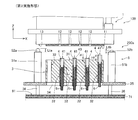
- FIG. 1 is a front cross-sectional view schematically showing an inkjet head cleaning device according to a first embodiment of the present invention. It is the top view which showed the upper surface of the base. It is explanatory drawing which showed the washing
- FIG. 1 is a front sectional view of a cleaning device 100a for an inkjet head 1 according to the first embodiment
- FIG. 2 is a plan view showing an upper surface 31 of a base 3.
- a cleaning apparatus 100a shown in FIG. 1 is an apparatus that cleans a nozzle surface 11 that includes a discharge port 12 of an inkjet head 1 that discharges a liquid serving as a coating liquid from a discharge port 12. Configured as part. For example, the inkjet head 1 is applied in another part of the inkjet coating apparatus 100 (not shown), and the nozzle surface 11 is lower than the lower end surface 13 of the inkjet head 1 by the thickness of the liquid repellent layer. If dirt or droplets that prevent application adhere and remain, the inkjet head 1 moves toward the cleaning device 100a. After cleaning the nozzle surface 11 with the cleaning device 100a to remove dirt and residual droplets, the inkjet head 1 returns to the original location of the inkjet coating device 100 and continues the coating operation.
- the lower end surface 13 is a nozzle peripheral surface that is a portion around the nozzle surface 11.
- the inkjet head 1 has an X direction in the longitudinal direction, and the nozzle surface 11 on which a large number of ejection ports 12 are arranged in the X direction corresponding to the X direction has a rectangular shape having a long side in the X direction.
- the cleaning device 100 a for the inkjet head 1 includes a block-shaped base 3, a gap setting unit 5 that defines a gap between the upper surface 31 of the base 3 and the nozzle surface 11 of the inkjet head 1, and the base 3.
- a recovery unit 9 that recovers the liquid falling downward, and a support elevating unit 7 that supports the base 3 and the recovery unit 9 to move up and down are configured.
- the cleaning operation is controlled by a control device including a computer (not shown) that is a part of the inkjet coating apparatus 100. Next, details of each part constituting the cleaning apparatus 100a will be described in order.
- an upper surface 31 is provided on the upper portion of the base 3 immediately below the inkjet head 1 during cleaning.
- the upper surface 31 is formed substantially flat and can face (oppose) the nozzle surface 11 of the inkjet head 1.
- the upper surface 31 is close to the nozzle surface 11 of the inkjet head 1 to a certain gap, and a liquid storage space R (see FIG. 3) for filling the liquid therebetween is formed. That is, the upper surface 31 is disposed close to the nozzle surface 11 so as to face the nozzle surface 11 and form the liquid storage space R when the nozzle surface 11 of the inkjet head 1 is cleaned.
- the base 3 supported by the support plate 35 with the legs 36 has a plurality of liquid recovery holes 32 that open at the upper surface 31 and are arranged along the longitudinal direction (X direction) of the nozzle surface 11.
- the liquid recovery hole 32 penetrates the base 3 in the vertical direction (Z direction) and is also opened on the lower surface 33 which is the opposite side of the upper surface 31 in the vertical direction.
- liquid recovery holes 32 are arranged at predetermined intervals along the longitudinal direction (X direction). Further, the recovery promoting member 4 is inserted into the three liquid recovery holes 32 excluding the two at both ends so as to be seen from the upper surface 31 side. When there is a liquid on the upper surface 31, the recovery promoting member 4 attracts the liquid to the liquid recovery hole 32 and has a function of promoting the recovery of the liquid into the liquid recovery hole 32. In order to express the function, the upper end surface 41 of the recovery promoting member 4 is protruded above the upper surface 31 of the base 3 by a protrusion amount of zero or more.
- the upper end surface 41 of the collection promoting member 4 at the center is projected by the largest projecting amount Hf, and the upper end surfaces 41 of the other collection promoting members 4 are projected by the projecting amount H smaller than the projecting amount Hf. Yes.
- the difference in the protruding amount by the recovery promoting member 4 is that the liquid recovery hole 32 (hereinafter referred to as “final liquid recovery hole”) in which the liquid recovery from the liquid storage space R is continued to the end. It is called "”.
- the support plate 35 that supports only the peripheral edge of the base 3 is provided with an opening 34 in the center, the recovery promoting member 4 can protrude downward from the lower surface 33 of the base 3. It has become.
- the lower side of the collection promoting member 4 may protrude from the lower side of the base 3 or may be within the base 3, and there is no functional difference.
- the opening 34 is also provided at a size and position so that the liquid recovered in the liquid recovery hole 32 can fall downward.
- the recovery promoting member 4 is disposed in the plurality of liquid recovery holes 32 so as to be exposed on the upper surface 31 and promotes the recovery of the liquid into the liquid recovery holes 32.
- the upper end surface 41 of the recovery promoting member 4 disposed in the final liquid recovery hole is positioned above the upper end surface 41 of the recovery promoting member 4 disposed in the other liquid recovery hole 32. 3 are arranged so as to protrude from the upper surface 31.
- the liquid recovery holes 32 including the recovery promoting member 4 are arranged in a straight line.
- This arrangement may be a non-linear arrangement such as a staggered arrangement.
- the recovery promoting member 4 is a hollow cylindrical main body having four slits 42 in a cross shape and having a predetermined length from the upper end surface 41 on the upper side in the vertical direction downward.
- the slit 42 having a length in the vertical direction and having a groove shape and the central through hole 43 serve as a liquid passage.
- both the slit 42 and the through-hole 43 have a shape formed so as to be a passage through which the liquid communicates with the liquid recovery hole 32 in the vertical direction from the upper end surface 41.
- the width Ls of the slit 42 as viewed from above is preferably 0.05 to 1 mm, more preferably 0.1 to 0.5 mm.
- the recovery promoting member 4 may be arranged so that the slit 42 is substantially parallel to the X direction or the Y direction, or the slit 42 is inclined at a certain angle with respect to the X direction or the Y direction. You may arrange
- the support elevating part 7 is an upper connecting body 75a, 75b that rotatably connects the upper part of the pistons 73a, 73b of the two air cylinders 74a, 74b and the lower side part of the support elevating plate 71, and the lower part of the air cylinder 74a.
- the lower connecting body 76a is rotatably connected to the base 72 and the lower connecting body 76b is connected to the lower portion of the air cylinder 74b by fastening.
- a pair of column portions 51a and 51b constituting the gap setting portion 5 and gap adjusting members 52a and 52b are also provided.
- the support lift plate 71 is lifted by the air cylinders 74 a and 74 b, and a pair of gap adjusting members 52 a and 52 b respectively provided at one end side and the other end side in the longitudinal direction (X direction) of the base 3 are provided at the lower end surface of the ink jet head 1.
- the gap G (see FIG. 3) between the upper surface 31 of the base 3 and the nozzle surface 11 of the inkjet head 1 is set according to the height Lt of the gap adjusting members 52a and 52b. be able to.
- the pair of gap adjusting members 52a and 52b comes into contact with a part of the inkjet head 1 in the vertical direction during cleaning, and thus the gap G between the upper surface 31 of the base 3 and the nozzle surface 11 of the inkjet head 1 is used. It stipulates.
- the contact part with the lower end surface 13 of the gap adjusting members 52a and 52b is a cylindrical surface (R surface). Further, even when the heights of the gap adjusting members 52a and 52b are made different from Lta and Ltb, respectively, the support elevating plate 71, the pistons 73a and 73b, and the base 72 are rotated by the upper coupling bodies 75a and 75b and the lower coupling body 76a.
- the gap adjusting members 52 a and 52 b can be brought into contact with the lower end surface 13.
- the gap between the upper surface 31 and the nozzle surface 11 is defined as a gap Ga on the gap adjusting member 52a side (see FIG. 6) and a gap Gb on the gap adjusting member 52b side (see FIG. 6). (It is not a parallel gap but an inclined gap).
- the base 3 and the support plate 35 are inside the collection tray 91 that constitutes the collection unit 9. Therefore, the liquid that overflows from the edge of the upper surface 31 of the base 3 and falls through the side surface of the base 3 and the support plate 35, and the liquid that falls through the inside of the liquid recovery hole 32 and the recovery promoting member 4, It is collected in the collection tray 91. It is preferable that the liquid collected in the collection tray 91 is discharged or discarded through a drain path (not shown).
- Step SA a method for cleaning the nozzle surface 11 as a method for cleaning the ink jet head of the present invention using the cleaning device 100a for the ink jet head 1 will be described following steps SA0 to SA3.
- the nozzle surface 11 is cleaned by discharging a coating liquid from the inkjet head 1 and collecting it by collecting dirt or residual droplets on the nozzle surface 11.
- 3 (a) to 3 (e) and FIG. 4 (f) are front sectional views showing a part of the inkjet head 1 and the base 3 shown in FIG. 1 and the periphery thereof (viewed in the Y direction). Figure) is shown.
- Steps SA0 to SA3 correspond to FIGS. 3A to 4F, and the situation at each step and the result of the operation of each part are shown. In step SA, the larger number is later in time.
- the step of forming the liquid storage space R by arranging the nozzle surface 11 of the inkjet head 1 and the upper surface 31 of the base 3 close to each other by performing Step SA whose execution status is shown in FIGS. And supplying the liquid between the nozzle surface 11 and the upper surface 31 of the base 3 to fill the liquid storage space R with liquid, and recovering the liquid in the liquid storage space R from the plurality of liquid recovery holes 32. And a step of cleaning the inkjet head.
- Step SA0 (Situation in FIG. 3A)
- the liquid storage space R is formed.
- the inkjet head 1 finishes coating, moves to a position immediately above the upper surface 31 of the base 3 and stops once for cleaning the nozzle surface 11 to which the dirt Di and the residual droplet M of the coating liquid adhere.
- the nozzle surface 11 and the upper surface 31 are substantially overlapped in the X and Y directions and face each other in the vertical direction.
- a liquid storage space R having a parallel gap G is formed between the nozzle surface 11 and the nozzle surface 11.
- the gap G is preferably 0.1 to 3 mm, more preferably 0.8 mm, because the liquid storage space R can be easily filled with liquid and the liquid can be reliably recovered from the liquid recovery hole 32. Set to 5 to 2 mm.
- Step SA1 is a step of filling the liquid storage space R with the coating liquid.
- a coating liquid is supplied to the inkjet head 1 and a predetermined amount of the coating liquid is discharged from the discharge port 12 at a predetermined flow rate (a liquid amount per unit time).
- the coating liquid is supplied to the liquid storage space R formed between the nozzle surface 11 and the upper surface 31 of the base 3, and the coating liquid is immediately filled to form the coating liquid mass 20.
- Excess coating liquid exceeding the volume of the liquid storage space R leaks from the upper surface 31 of the base 3 and is finally collected in the collection tray 91.
- the recovery of the liquid by the liquid recovery hole 32 is started from the time when the coating liquid fills the liquid storage space R. For this reason, in order to maintain the coating liquid full state of the liquid storage space R for a predetermined time, it is necessary to continue supplying the coating liquid to the liquid storage space R for a predetermined time.
- the dirt Di and residual droplet M on the nozzle surface 11 are included in the coating liquid in the liquid storage space R and are separated from the nozzle surface 11 during the time for maintaining the liquid storage space R in the state where the coating liquid is full.
- the time for maintaining the liquid storage space R in the state where the coating liquid is filled is preferably 0.1 to 10 seconds, more preferably 1 to 5 seconds.
- Step SA2 (Situations in FIGS. 3C to 3E)
- the coating liquid in the liquid storage space R is recovered from the plurality of liquid recovery holes 32.
- the collection of the liquid from each liquid collection hole 32 is started from the time when the liquid storage space R is filled with the coating liquid, and the coating liquid in the liquid storage space R is discharged with the completion of the discharge of the coating liquid from the inkjet head 1.
- the volume of (coating liquid mass 20) decreases. More precisely, since the recovery promoting member 4 is inserted into the three central liquid recovery holes 32, the coating liquid is recovered through the through hole 43 of the recovery promoting member 4 in the liquid recovery hole 32.
- both the boundaries 21a and 21b on the left and right of the coating liquid mass 20 move from both ends to the center.
- the movement of the boundaries 21a and 21b of the coating liquid mass 20 is not necessarily symmetrical. For example, the boundary 21b on the right side is closer to the center (the state shown in FIG. 3C).
- the coating liquid is recovered from the liquid recovery hole 32 in contact with the coating liquid mass 20
- the aggregation of the coating liquid accompanying the decrease in the volume of the coating liquid in the liquid storage space R further progresses.
- the boundary 21b on the right side of the coating liquid lump 20 first stops in the vicinity of the recovery promoting member 4 of the central liquid recovery hole 32 (final liquid recovery hole), and the boundary on the left side of the coating liquid lump 20 It waits for 21a to move to the central liquid recovery hole 32 (state shown in FIG. 3D).
- the upper end surface 41 of the recovery promoting member 4 inserted into the central liquid recovery hole 32 has a protrusion amount Hf protruding above the upper surface 31 of the base 3, and the upper end surface 41 of the other recovery promoting member 4 protrudes. It is larger than the amount H.
- the holding force for holding the coating liquid mass 20 by the surface tension of the collection promoting member 4 with the protruding amount Hf is larger than the holding force for the collecting promoting member 4 with the protruding amount H. Therefore, as shown in FIG. 3 (d), even if the central collection promotion member 4 and the collection promotion member 4 on the left side of the central collection promotion member 4 are attracted by the respective holding forces, the central collection promotion member 4 having a large holding force is moved toward the center.
- the coating liquid mass 20 can be drawn.
- the boundary 21 b on the right side of the coating liquid mass 20 remains stopped on the right side of the collection promoting member 4 in the center, and the boundary 21 a on the left side of the coating liquid mass 20 recovers the liquid from the liquid recovery hole 32.
- the central liquid recovery hole 32 final liquid recovery hole (state shown in FIG. 3E).
- step SA2 the coating liquid between the nozzle surface 11 and the upper end surface 41 of the central collection promoting member 4 is collected, and the collection ends.
- Step SA3 (Situation in FIG. 4F) This is a cleaning end step.
- the air cylinders 74a and 74b are operated to the opposite side, the base 3 is pulled away from the inkjet head 1 and moved downward (the state shown in FIG. 4 (f)). Then, the inkjet head 1 moves to a predetermined location for the next application.
- the cleaning device 100a for the inkjet head 1 includes a plurality of liquid recovery holes 32, and further includes a recovery promoting member 4 that draws liquid to the liquid recovery holes 32 and promotes recovery of the liquid. Yes.
- the liquid in the liquid storage space R can be recovered directly from the liquid recovery hole 32.
- the liquid in the liquid storage space R can be recovered without remaining on the nozzle surface 11 while the ink jet head 1 is stationary without being moved as in the prior art. Since the liquid is moved and collected only in the liquid storage space R, dirt and liquid adhere to the nozzle peripheral surface (lower end surface 13) that is around the nozzle surface 11 and is outside the range of the liquid storage space R.
- the nozzle surface can be obtained by arranging the liquid recovery holes 32 and the recovery promoting members 4 in the longitudinal direction at an appropriate interval and number.
- the liquid in the liquid storage space including dirt and residual liquid droplets attached to 11 can be recovered.
- the cleaning can be reliably performed with high quality.
- the upper end surface 41 of the recovery promoting member 4 protrudes from the upper surface 31 of the base 3, and the protruding amount is not uniform throughout the recovery promoting member 4, and at least the recovery promoting member 4 having the maximum protruding amount is at least 1. More specifically, there is an upper end surface 41 of the recovery promoting member 4 disposed in the liquid recovery hole 32 (final liquid recovery hole) where the recovery of the liquid from the liquid storage space R is continued until the end. Since the longest protrusion from the upper surface 31 of the base 3 (protrusion amount Hf) occurs, the liquid lump (coating liquid lump 20) that moves with the volume decreasing in the liquid storage space R as the liquid is recovered is collected. The liquid can be steadily held and guided to the liquid recovery hole 32 where the recovery is continued until the end. Thereby, all the liquid in the liquid storage space R can be collected without remaining. As a result, it is possible to collect all dirt and residual droplets attached to the nozzle surface 11 included in the liquid in the liquid storage space R.
- the cleaning device 100a for the ink jet head 1 of the first embodiment only the liquid is brought into contact with the nozzle surface 11 with respect to the large ink jet head 1 in which the size of the nozzle surface 11 is increased.
- the liquid recovery is continued until the end by utilizing the fact that the recovery of the liquid is continued to the end in the liquid recovery hole 32 in which the recovery promoting member 4 having the maximum protrusion amount from the upper surface 31 of the base 3 is arranged.
- the location to be set can be set arbitrarily.
- the recovery promoting member 4 having the maximum protrusion amount from the upper surface 31 of the base 3 is provided in the liquid recovery hole 32 in the substantially central portion among the plurality of liquid recovery holes 32 arranged. If the configuration is such that the moving distance of the liquid interface (boundary 21a, boundary 21b) is the distance from the end of the base 3 to the center of the base 3 at the longest, the liquid recovery time should be shortened. Can do.
- the recovery facilitating member 4 that maximizes the amount of protrusion from the upper surface 31 of the base 3 is provided in the liquid recovery hole 32 at the end of the plurality of liquid recovery holes 32 arranged side by side. If it comprises, the collection
- the recovery promoting member 4 is formed with the slit 42 which is a passage through which the liquid communicates with the liquid recovery hole 32 in the vertical direction from the upper end surface 41. Therefore, the liquid on the upper surface 31 of the base 3 can be guided into the liquid recovery hole 32 and all the liquid in the liquid storage space R can be reliably recovered.
- the gap adjusting members 52 a and 52 b at both ends in the longitudinal direction are brought into contact with the lower end surface 13 that is a part of the inkjet head 1 to form the liquid storage space R.
- the gap between the upper surface 31 and the nozzle surface 11 was always kept constant. As a result, the liquid in the liquid storage space R can be recovered and cleaned under the same optimal conditions for each cleaning, and thus the nozzle surface 11 can be cleaned stably and reliably even after repeated times. .
- the liquid in the liquid storage space R does not remain on the nozzle surface 11 in a state where the ink jet head 1 is stationary without moving by performing the above-described steps.
- the nozzle surface 11 can be cleaned even with respect to the inkjet heads 1 arranged in a row corresponding to the wide width.
- the inkjet head 1 has the elongated nozzle surface 11, the liquid containing dirt and residual droplets attached to the nozzle surface 11 in the liquid storage space R is reliably recovered from the liquid recovery hole 32. can do.
- the portion around the nozzle surface 11 is contaminated.
- high quality cleaning of the nozzle surface 11 can be performed reliably by preventing the liquid from adhering or remaining.
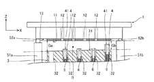
- FIG. 5 is an enlarged front sectional view schematically showing the inkjet head cleaning device 200a according to the second embodiment
- FIG. 6 is a base when the liquid storage space R is formed by the cleaning device 200a of the second embodiment
- 3 is an enlarged front sectional view showing a relative positional relationship between the upper surface 31 of No. 3 and the nozzle surface 11.
- the cleaning apparatus 200a according to the second embodiment shown in FIG. 5 is the same as that except that the flow rate adjusting member 6 is added to the recovery promoting member 4, and the number and position of the recovery promoting member 4 and the final liquid recovery hole are changed. This is the same as the cleaning device 100a of the first embodiment.
- the recovery promoting member 4 into which the flow rate adjusting member 6 is inserted is inserted into the four liquid recovery holes 32 other than the liquid recovery hole 32 at the left end.
- the recovery promoting member inserted into the liquid recovery hole 32 at the right end part 4 is protruded from the upper surface 31 by the largest protrusion amount Hf.
- the other upper end surfaces 41 of the three collection promoting members 4 are projected by a projection amount H smaller than the projection amount Hf.
- the flow rate adjusting member 6 is provided separately from the recovery promoting member 4, is disposed in the liquid recovery hole 32, and the flow rate of liquid flowing downward in the liquid recovery hole 32 (liquid amount per unit time). Is to adjust.
- the cleaning device 200a can adjust the recovery speed and recovery time of the liquid filled in the liquid storage space R.
- the liquid recovery rate from the liquid recovery hole 32 can be reduced. That is, the flow rate of liquid passing through the liquid recovery hole 32 can be adjusted by the insertion amount Li of the flow rate adjusting member 6 into the recovery promoting member 4. Thereby, the recovery speed of the liquid filled in the liquid storage space R can be arbitrarily adjusted.
- the flow rate adjusting member 6 is inserted into the recovery promoting member 4 inside the liquid recovery hole 32 and has a shape that adjusts the flow rate of the liquid according to the insertion amount Li.
- the insertion amount Li of the flow rate adjusting member 6 to the recovery promoting member 4 is all the same for convenience, but the flow rate adjustment is performed by changing the insertion amount Li for each recovery promoting member 4 as necessary. Also good.
- the cross-sectional shape through which the liquid of the flow rate adjusting member 6 passes may be any shape such as a circle, rectangle, or polygon. Furthermore, the cross-sectional shape including one slit 42 penetrating from the upper end surface 41 to the lower side in the recovery promoting member 4 may be applied to the cross-sectional shape of the flow rate adjusting member 6 as it is.
- the heights of the gap adjusting members 52a and 52b are Lta and Ltb, respectively, and the height Ltb is smaller than the height Lta.
- the gap in the liquid storage space R formed by raising the base 3 and bringing the gap adjusting members 52a and 52b into contact with the lower end surface 13 of the inkjet head 1 is as shown in FIG.
- the gap Gb at the portion is smaller than the gap Ga at the left end portion.
- the gap of the liquid storage space R is made the smallest with the gap Gb. That is, an inclined gap in which the gap gradually decreases toward the right end portion is set.
- the smaller gap Gb is preferably 0.1-2 mm, more preferably 0.5-1.5 mm, and the gap difference Ga-Gb is preferably 0.1-1 mm, more preferably 0.2-0. 7 mm.
- the coating liquid is discharged from the ink jet head 1 to fill the coating liquid into the liquid storage space R in which the gaps Ga and Gb are set in the above preferable range and the inclined gap is provided. .
- the coating liquid is recovered from each liquid recovery hole 32 from the time when the coating liquid is filled, and progresses and the volume of the coating liquid becomes smaller than the volume of the liquid storage space R, the coating liquid aggregates to form a gap G. Let's approach the smaller one. That is, the coating liquid moves toward the liquid recovery hole 32 (final liquid recovery hole) at the right end, which is the smallest gap Gb in the liquid storage space R.
- the coating liquid filled in the liquid storage space R can be finally reliably recovered from the liquid recovery hole 32 at the right end.
- the aggregation of the coating liquid accompanying the decrease in the volume of the coating liquid due to the recovery of the coating liquid from the liquid recovery hole 32 is slow, that is, the coating liquid moves to the right side. Is slow, the coating solution is divided in the middle.
- the divided right-side coating liquid is collected from the liquid recovery hole 32 at the right end, but the divided left-side coating liquid remains in the liquid storage space R as it is. Therefore, in order to reliably recover the liquid filled in the liquid storage space R in the state of FIG. 6, the corresponding flow rate adjustment is performed so that the recovery rate from the liquid recovery hole 32 where the liquid recovery continues until the end is minimized. It is preferable to adjust the insertion amount Li of the member 6 into the collection promoting member 4.
- the flow rate adjusting member 6 disposed in the liquid recovery hole 32 is provided separately from the recovery promoting member 4.
- the liquid recovery rate from the liquid recovery hole 32 can be optimized by adjusting the flow rate of the liquid through the liquid recovery hole 32 by the flow rate adjusting member 6. This prevents inconveniences such as the recovery speed is too high to cause droplets to remain on the nozzle surface, or the recovery speed from the plurality of liquid recovery holes is different and the liquid is divided and remains in the liquid storage space. be able to.
- the flow rate adjusting member 6 can adjust the flow rate of liquid passing through the liquid recovery hole 32 by the amount Li inserted into the recovery promoting member 4, the recovery rate from the liquid recovery hole 32 can be easily optimized. The liquid can be recovered without leaving the liquid in the nozzle surface 11 or the liquid storage space R.
- the cleaning device 200a as in the first embodiment, only the liquid is brought into contact with the nozzle surface 11 with respect to the large inkjet head 1 in which the size of the nozzle surface 11 is increased.
- high quality cleaning of the nozzle surface 11 can be reliably performed by preventing dirt and liquid from adhering to or remaining on the portion around the nozzle surface 11.
- the liquid recovery hole 32 at the right end portion immediately below the region where the discharge port 12 does not exist on the nozzle surface 11 is used as the liquid recovery hole (the liquid recovery hole (from which the liquid recovery from the liquid storage space R continues until the end).
- the liquid recovery hole from which the liquid recovery from the liquid storage space R continues until the end.
- Final liquid recovery hole Therefore, even if the liquid repellency of the nozzle surface 11 is deteriorated and the liquid remains immediately above the liquid recovery hole 32 at the right end portion, the liquid does not interfere with the discharge port 12, so that the coating liquid is normally discharged from the discharge port 12. As a result, the application operation of the inkjet head 1 can be continued.
- FIG. 7 is a front sectional view schematically showing an inkjet head cleaning device 300a according to the third embodiment.
- the cleaning apparatus 300a of the third embodiment shown in FIG. 7 is exactly the same as the cleaning apparatus 200a of the second embodiment, except that it further includes a cleaning liquid supply means 8 for supplying a cleaning liquid into the liquid storage space R. .
- the cleaning liquid supply means 8 is inserted into the liquid recovery hole 32 at the left end and is connected to a hollow cylindrical cleaning liquid supply pipe 81 that discharges the cleaning liquid upward, and is connected to the lower end of the cleaning liquid supply pipe 81 and sent from the pump 83.
- the cleaning liquid pipe 82 supplies the cleaning liquid to be supplied to the cleaning liquid supply pipe 81, and the storage tank 84 stores the cleaning liquid and supplies the cleaning liquid to the pump 83.
- the cleaning liquid supply pipe 81 is a supply member that can be supplied with the cleaning liquid inside any of the liquid recovery holes 32, and is provided in the cleaning liquid supply means 8.
- the cleaning liquid supply means 8 supplies a predetermined amount of cleaning liquid from the pump 83 to the liquid storage space R in which the upper surface 31 of the base 3 is formed close to the nozzle surface 11 of the inkjet head 1 at an arbitrary timing. Can be charged. It is preferable that the upper end surface of the cleaning liquid supply pipe 81 is disposed at the same position as the upper surface 31 or slightly below the upper surface 31.
- the step of forming the liquid storage space R by arranging the nozzle surface 11 of the inkjet head 1 and the upper surface 31 of the base 3 close to each other by performing Step SB whose execution status is shown in FIGS. And supplying the liquid between the nozzle surface 11 and the upper surface 31 of the base 3 to fill the liquid storage space R with liquid, and recovering the liquid in the liquid storage space R from the plurality of liquid recovery holes 32. And a step of recovering the cleaning liquid from the plurality of liquid recovery holes 32 after supplying the cleaning liquid into the liquid storage space R by the cleaning liquid supply means 8 for supplying the cleaning liquid into the liquid storage space R.
- An ink jet head cleaning method is realized.
- Step SB0 (Situation in FIG. 8A)
- the liquid storage space R is formed.
- the cleaning liquid supply means 8 has completed the preparation work of filling the cleaning liquid up to the upper end surface of the cleaning liquid supply pipe 81 (slightly below the upper surface 31 of the base 3), and can supply the cleaning liquid at any time.
- the air cylinders 74a and 74b are operated to raise the base 3 and have a height different from that of the lower end surface 13 of the inkjet head 1.
- Lta, Ltb (Lta> Ltb) gap adjusting members 52a, 52b are brought into contact with each other, and a gap Ga at the left end and a gap Gb (Ga> Gb) at the right end are provided between the upper surface 31 and the nozzle surface 11.
- the liquid storage space R is formed as a space inclined at.
- Step SB1 (Situation in FIG. 8B)
- the liquid storage space R is filled with the coating liquid.
- a coating liquid is supplied to the inkjet head 1 and a predetermined amount of the coating liquid is discharged from the discharge port 12 at a predetermined flow rate (a liquid amount per unit time).
- the coating liquid discharged from the discharge port 12 fills the liquid storage space R and becomes a coating liquid lump 20.
- the excess coating liquid exceeding the volume of the liquid storage space R leaks from the upper surface 31 of the base 3 and is finally collected on the collection tray 91.
- the dirt Di and the residual droplet M on the nozzle surface 11 are included in the coating liquid mass 20 which is the coating liquid in the liquid storage space R. It separates from the nozzle surface 11.
- the cleaning liquid on and around the liquid recovery hole 32 at the left end is attracted to the second liquid recovery hole 32 from the left end and is partially recovered therefrom.
- Step SB2 (Status of FIGS. 8C and 8D)
- the coating liquid (coating liquid mass 20) in the liquid storage space R is recovered from the plurality of liquid recovery holes 32. From the point of time when the liquid storage space R is filled with the coating liquid, recovery of the liquid from each liquid recovery hole 32 is started. The coating liquid on and around the liquid recovery hole 32 at the left end cannot be recovered from the liquid recovery hole 32 at the left end, but is partially drawn from the liquid recovery hole 32 drawn from the left end. Is done. Now, the volume of the coating liquid mass 20 in the liquid storage space R decreases with the end of the discharge of the coating liquid from the inkjet head 1.
- the coating liquid mass 20 When the volume of the coating liquid mass 20 becomes smaller than the volume of the liquid storage space R, the coating liquid aggregates due to the action of surface tension, and the coating liquid mass 20 approaches the side where the gap G of the liquid storage space R is small. . That is, the boundary 21a on the left side of the coating liquid mass 20 moves in the right direction where the gap G gradually decreases. The boundary 21b on the right side of the coating liquid mass 20 is in the vicinity of the recovery promoting member 4 at the right end and does not move (the state shown in FIG. 8C). Further, when the recovery of the coating liquid from the liquid recovery hole 32 in contact with the coating liquid mass 20 progresses, the aggregation of the coating liquid accompanying the decrease in the volume of the coating liquid mass 20 in the liquid storage space R further progresses.
- the boundary 21a on the left side of the lump 20 moves toward the liquid recovery hole 32 (final liquid recovery hole) at the right end. Then, the recovery of the liquid from the liquid recovery hole 32 at the right end is continued until the end, and all the coating liquid (coating liquid mass 20) in the liquid storage space R is recovered (the state shown in FIG. 8D). .
- Step SB3 (Situation in FIG. 9E)
- the cleaning liquid supply means 8 supplies the cleaning liquid into the liquid storage space R and fills it.
- the pump 83 is driven, and a predetermined amount of cleaning liquid is sent from the cleaning liquid supply pipe 81 to the liquid storage space R at a predetermined flow rate (liquid amount per unit time).
- a predetermined flow rate liquid amount per unit time
- the coating liquid is fed to the liquid storage space R by the start of feeding of the cleaning liquid, and finally the liquid is stored as surplus liquid. It is discharged out of R.
- the dirt Di and the coating liquid remain on the nozzle surface 11 due to the decrease in the liquid repellency of the nozzle surface 11, the remaining dirt Di and the remaining time for maintaining the filling of the cleaning liquid in the liquid storage space R
- the coating solution is dissolved in the cleaning solution and included in the cleaning solution. At the time of dissolution, the dirt Di and the coating liquid are separated from the nozzle surface 11.
- Step SB4 (Situations in FIGS. 9F and 9G)
- the cleaning liquid in the liquid storage space R is recovered from the plurality of liquid recovery holes 32. From the time when the cleaning liquid is filled in the liquid storage space R, the recovery of the cleaning liquid is started from all the liquid recovery holes 32 other than the left end. Although the cleaning liquid on and around the liquid recovery hole 32 at the left end cannot be recovered from the liquid recovery hole 32 at the left end, it is attracted to the second liquid recovery hole 32 from the left end and is partially recovered therefrom. The With the end of the supply of the cleaning liquid from the cleaning liquid supply pipe 81, the recovery from the liquid recovery hole 32 progresses, and the volume of the cleaning liquid mass 22 in the liquid storage space R decreases.
- the cleaning liquid aggregates, and the boundary 23a on the left side of the cleaning liquid mass 22 moves to the right in which the gap G gradually decreases.
- the boundary 23b on the right side of the cleaning liquid mass 22 is in the vicinity of the recovery promoting member 4 inserted in the liquid recovery hole 32 (final liquid recovery hole) at the right end and does not move (state shown in FIG. 9 (f)). ).
- the recovery of the coating liquid from the liquid recovery hole 32 in contact with the cleaning liquid mass 22 further progresses, the aggregation of the cleaning liquid accompanying the decrease in the volume of the cleaning liquid mass 22 in the liquid storage space R further progresses, and the left side of the cleaning liquid mass 22
- the boundary 23a further moves toward the liquid recovery hole 32 (final liquid recovery hole) at the right end.
- Step SB5 (Situation in FIG. 9H) This is a cleaning end step.
- the air cylinders 74a and 74b are operated to the opposite side, and the base 3 is separated from the inkjet head 1 and moved downward (the state shown in FIG. 9 (h)). Then, the ink jet head 1 moves up to a predetermined place after being lifted once for the next application.
- the cleaning method shown in the above steps SB0 to SB5 is effective when the liquid repellency of the nozzle surface 11 is deteriorated. That is, at the time when the process is performed up to step SB2, the dirt Di and the remaining liquid droplets of the coating liquid that have first adhered to the nozzle surface 11 can be removed, but when the coating liquid filled in the liquid storage space R is recovered, If the liquid repellency of the nozzle surface 11 is deteriorated, the recovered coating liquid may adhere to the nozzle surface 11 and remain. Further, when the liquid repellency of the nozzle surface 11 is further deteriorated, the dirt Di and the residual liquid droplets of the coating liquid that have first adhered to the nozzle surface 11 may not be removed.
- the cleaning liquid that is supplied and filled in the liquid storage space R remains on the nozzle surface 11. It is possible to dissolve the dirt and coating liquid that is dissolved and include it in the cleaning liquid, and it is possible to collect all the cleaning liquid including the dirt and residual coating liquid. Can be reliably washed.
- the above-described cleaning method may be performed in the order of steps SB0 ⁇ SB3 ⁇ SB4 ⁇ SB1 ⁇ SB2 ⁇ SB5.
- the dirt Di and residual droplets adhering to the nozzle surface 11 can be reliably removed with the cleaning liquid that is first supplied to the liquid storage space R to be filled.
- the foreign matter adheres to the nozzle surface 11 and the liquid repellency is deteriorated, the foreign matter can also be removed from the nozzle surface 11 by the cleaning liquid, so that the liquid repellency of the nozzle surface 11 can be recovered.
- the cleaning liquid enters the inside of the inkjet head 1 from the discharge port 12, and the coating liquid is discharged due to the cleaning liquid entering the interior when the inkjet head 1 is applied after cleaning. There are things that cannot be done. If cleaning is performed in the order of the above steps, after the nozzle surface 11 is cleaned with the cleaning liquid, the coating liquid is supplied from the inkjet head 1 to the liquid storage space R and recovered, so that even if the cleaning liquid is once in the inkjet head 1. The cleaning liquid that has entered the inside is also discharged to the outside by the subsequent discharge of the coating liquid from the inkjet head 1.
- the repellency of the nozzle surface 11 can be recovered by cleaning the nozzle surface 11 with the first cleaning liquid, the nozzle surface 11 can be recovered even if the coating liquid is supplied to the liquid storage space R and the coating liquid is subsequently recovered. No coating liquid remains on the nozzle surface 11 and the nozzle surface 11 can be cleaned with the coating liquid.
- the cleaning method described above may be performed in the order of steps SB0 ⁇ SB3 ⁇ SB4 ⁇ SB5.
- the dirt Di and residual droplets adhering to the nozzle surface 11 can be reliably removed in a short time with the cleaning liquid that is first supplied to the liquid storage space R to be filled.
- the cleaning liquid supply means 8 for supplying the cleaning liquid into the liquid storage space R is provided, so that the nozzle surface 11 can be cleaned by filling the liquid storage space R with the cleaning liquid.
- the liquid repellency of the nozzle surface 11 is deteriorated, the adhered dirt and droplets can be surely removed, and the liquid repellency of the nozzle surface 11 can be recovered.
- the cleaning liquid supply pipe 81 of the cleaning liquid supply means 8 for supplying the cleaning liquid directly into the liquid storage space R is provided in the liquid recovery hole 32 as a supply member capable of supplying the cleaning liquid, the liquid recovery hole 32 is supplied with the cleaning liquid. It can also be used as a hole. As a result, since it is not necessary to provide a separate dedicated cleaning liquid supply hole in the base 3 in addition to the liquid recovery hole 32, the apparatus configuration can be simplified.
- the cleaning device 300a only the liquid is applied to the nozzle surface 11 with respect to the large-sized inkjet head 1 in which the size of the nozzle surface 11 is increased, as in the first and second embodiments.
- the nozzle surface 11 and the upper surface 31 are kept stationary so that dirt and liquid do not adhere to and remain on the portion around the nozzle surface 11. Can be reliably washed.
- the coating liquid to which the cleaning apparatus and the cleaning method of the present invention can be applied is all applicable as long as it is a liquid that can be applied by being discharged from an inkjet head.
- the present invention can be suitably applied to a liquid containing an ultraviolet curable resin or other resin material in addition to an ink in which a dye or pigment is dissolved or dispersed in a solvent.
- the material of the base 3, the collection promoting member 4, and the flow rate adjusting member 6 may be any material such as metal, ceramics, and synthetic resin.
- those having resistance to them are preferable, such as stainless steel having resistance and corrosion resistance to the organic solvent and water often used in the coating liquid and cleaning liquid for the inkjet head. Preferably used.
- the size of the upper surface 31 of the base 3 is preferably the same as that of the nozzle surface 11 of the inkjet head 1, or the upper surface 31 is preferably made larger by 0.1 to 2 mm in the X and Y directions. This is because the liquid storage space R can be filled with the liquid stably.
- the diameter of the liquid recovery hole 32 is preferably ⁇ 0.5 to 5 mm, more preferably ⁇ 1 to 3 mm.
- the recovery promoting member 4 may be a member having a shape that allows the liquid to flow in the liquid recovery hole 32 from the portion protruding above the upper surface 31 and flow in the vertical direction.
- it is a plate material that is long in the vertical direction, and is “1” -shaped, triangular, trapezoidal, polygonal, circular, elliptical, U-shaped, V-shaped, Y-shaped, U-shaped in plan view from above Even those formed in the shape of a ring, a cross-beam, etc. function as a recovery promoting member.
- the length in the vertical direction of the recovery promoting member 4 is not particularly limited, but is preferably 1 mm or more and 30 mm or less, more preferably 10 mm or more and 25 mm or less because of the length that the liquid travels and is easy to install.
- the liquid immediately above can be recovered, but the liquid around the liquid recovery hole cannot be recovered.
- the recovery promoting member is inserted into the liquid recovery hole, the liquid around the liquid recovery hole can be drawn toward the liquid recovery hole and recovered.
- the amount of protrusion (H, Hf) from the upper surface 31 of the upper end surface 41 of the recovery promoting member 4 inserted into the liquid recovery hole 32 preferably the gap G of the liquid storage space R at the position where the recovery promoting member 4 is located. It is 0 to 90%, more preferably 10 to 80%.
- the amount of protrusion from the upper surface 31 of the upper end surface 41 of the recovery promoting member 4 inserted into the normal liquid recovery hole 32 other than the final liquid recovery hole 32 may be zero, that is, the position of the upper end surface 41 may be substantially the same as the upper surface 31.
- the recovery promoting member 4 is provided with a slit 42. If the liquid comes into contact with the slit 42, the liquid is transported downward by capillary action, so that the surrounding liquid can be drawn without being interrupted.
- the liquid recovery hole final liquid recovery hole in which the liquid recovery from the liquid storage space R is continued until the end is a liquid recovery hole 32 provided in the center in the longitudinal direction.
- the liquid recovery hole 32 at the right end has been described.
- the present invention is not limited to this, and any liquid recovery hole 32 may be used.
- the number of the recovery facilitating members 4 with the maximum protrusion amount is not limited to one, but the recovery facilitating member 4 with the maximum protrusion amount is inserted into the liquid recovery hole 32 between the center and the right end portion, The final liquid recovery hole may be selected.
- the protrusion amounts from the upper surface 31 of the upper end surface 41 of the recovery promoting member 4 inserted into the plurality of liquid recovery holes 32 other than the final liquid recovery hole are all set to the same protrusion amount H.
- the amount of protrusion may be different for each collection promoting member 4. These projection amounts are required to be smaller than the projection amount Hf from the upper surface 31 of the upper end surface 41 of the recovery promoting member 4 inserted into the final liquid recovery hole. Further, in this case, it is preferable that the protrusion amount of the upper end surface 41 of each recovery promoting member 4 is made smaller as the distance from the recovery promoting member 4 where the protrusion amount inserted into the final liquid recovery hole becomes maximum is increased.
- liquid recovery proceeds in the order from the liquid recovery hole in which the recovery promoting member 4 having a small protrusion amount is inserted to the liquid recovery hole in which the recovery promoting member 4 having a large protrusion amount is inserted.
- the process of recovering the liquid smoothly proceeds in the liquid recovery hole (final liquid recovery hole) in which the recovery promoting member 4 having the largest protrusion amount is inserted.
- the pair of gap adjusting members 52a and 52b are brought into contact with the lower end surface 13 to determine the relative positions of the nozzle surface 11 and the upper surface 31, but without using the gap adjusting members 52a and 52b.
- the relative position between the nozzle surface 11 and the upper surface 31 may be determined.
- the gap adjusting members 52a and 52b may be brought into contact with the lower end surface 13 via an intermediate member having a constant thickness instead of directly contacting the lower end surface 13 of the inkjet head 1.
- the intermediate member has a function of protecting the lower end surface 13.
Landscapes
- Ink Jet (AREA)
Abstract
ノズル面の寸法が長大化された大型のインクジェットヘッドに対して、ノズル面に液体のみを接触させる非接触洗浄を行う場合に、ノズル面の周囲にある部分に汚れや液体が付着、残存しないようにして、ノズル面の高品質の洗浄を確実に行うことが可能なインクジェットヘッドの洗浄装置と洗浄方法を提供する。具体的には、このインクジェットヘッド1の洗浄装置100aは、ノズル面11の洗浄時に、ノズル面11と対面して貯液空間Rを形成する上面31と、上面31で開口し、ノズル面11の長手方向に沿って並ぶ複数の液体回収孔32とを含む基台3と、上面31に露出するように複数の液体回収孔32に配置される回収促進部材4とを備える。各回収促進部材4の上端面41は、基台3の上面31から突出しており、その突出量は回収促進部材4全体で一様ではなく、突出量が最大となる回収促進部材4が少なくとも1つ存在する。
Description
この発明は、インクジェットヘッドの洗浄装置およびインクジェットヘッドの洗浄方法に関する。
インクジェットヘッドは、微細な液滴状の塗布液を多数回にわたって繰り返して吐出するため、その安定稼働には、塗布液が吐出される吐出口を常に清浄に保って、塗布液が何にも妨げられない状態で吐出できることが必要となる。そのために、インクジェットヘッド塗布装置は、塗布液の吐出口とその周囲にあるノズル面に残留する汚れや液滴を除去する洗浄装置を必ず備えている。このようなインクジェットヘッド用の洗浄装置としては、例えば、インクジェットヘッドのノズル面に、清掃部材を摺動させたり押し当てたりせず、液体(洗浄液など)のみを接触させて汚れや液滴の除去を行う洗浄装置が知られている(たとえば、特許文献1参照)。
特許文献1に開示されているインクジェットヘッドの洗浄装置では、洗浄液保持プレートに形成された洗浄液保持面が、インクジェットヘッドの撥液処理されたノズル面との間に、洗浄液を膜状に保持できるように配置される。そして、インクジェットヘッドのノズル面を、洗浄液保持面上に保持された洗浄液(液体)と接触させながら、洗浄液保持面の上方で水平移動させる。この時、吐出口やノズル面に付着した汚れや塗布液の残留液滴は、洗浄液に接触することにより、吐出口やノズル面から除去される。そしてインクジェットヘッドの移動速度が適切に制御されているなら、撥液性のあるノズル面は、除去された汚れや残留液滴を含む洗浄液(液体)が付着することなく離れていけるので、最終的にはインクジェットヘッドの吐出口やノズル面にあった汚れや残留液滴が除去されることになる。すなわち、インクジェットヘッドの吐出口やノズル面の洗浄が、洗浄液保持面と非接触で行える。なお、汚れや残留液滴を含む洗浄液(液体)は、ノズル面よりも濡れ性の高い洗浄液保持面に残留することになる。
特許文献1に記載されたインクジェットヘッドの洗浄装置では、洗浄液保持プレートに対するインクジェットヘッドの水平移動により、原理的には、汚れや残留液滴を含む洗浄液は撥液処理されたノズル面には残留せず、より濡れ性の高い洗浄液保持面に残留すると考えられる。しかしながら、実際のインクジェットヘッドでは、撥液処理されたノズル面だけが際立って突き出ているのではなくて、ノズル面の周囲にもヘッドを構成する部分がノズル面と同一面上、あるいは数10~数100μmの段差分離れた面上に存在する。ノズル面の周囲でインクジェットヘッドを構成する部分がある面をノズル周囲面と呼ぶことにすると、ノズル周囲面は通常は撥液処理されていない。したがって、液体と接触するノズル面が移動して、ノズル面の移動方向に隣り合うノズル周囲面が液体と接触すると、ノズル面には付着しなかった液体がノズル周囲面には付着して残留することになる。この場合に、ノズル周囲面に汚れを含んだ液体が残存したまま、インクジェットヘッドで塗布を行おうとすると、インクジェットヘッドのノズル面を基板に近接させた時に、ノズル周囲面に残存した液体を、基板に付着させてしまうおそれがある。
また、実際のインクジェットヘッドの塗布装置では、多数のインクジェットヘッドを長手方向に密に1列状に並べて、広幅に対応して塗布できるようにしている。このような1列状に密に多数並んだインクジェットヘッドのノズル面に付着した汚れや塗布液の残留液滴を除去するために、上記特許文献1の手段を適用して、洗浄液保持プレートをインクジェットヘッドと同じ様に1列状に密に多数並べて、洗浄液保持プレートの洗浄液保持面上に保持された洗浄液に、インクジェットヘッドのノズル面を接触させながら水平移動させることが考えられる。しかしながら、水平移動によって一つのインクジェットヘッドのノズル面の洗浄を行えても、すぐに隣の洗浄液保持面上の汚れや残留液滴を含んだ洗浄液に接することになるので、ノズル周囲面に液滴が付着するし、ノズル面にも汚れが再付着する可能性が非常に高くなる。
以上の特許文献1の手段による問題を回避するには、インクジェットヘッドを移動させることなく静止した状態で、ノズル面と洗浄液保持面に接触する洗浄液を回収することで、ノズル面の洗浄を行えるようにすればよいのであるが、それを実現する公知の手段はない。とりわけ塗布幅を大きくするためにノズル面の寸法が長手方向に長大化されたインクジェットヘッドにも適用できるものは皆無、というのが現状である。
この発明は、上記の問題を解決するためになされたものであり、その主たる目的は、ノズル面の寸法が長手方向に長大化された大型のインクジェットヘッドや広幅に対応して1列状に多数配置されたインクジェットヘッドに対して、ノズル面に液体のみを接触させて行う非接触洗浄を行う場合に、ノズル面の周囲にある部分に汚れや液体が付着、残存しないようにして、ノズル面の高品質の洗浄を確実に行うことが可能なインクジェットヘッドの洗浄装置およびインクジェットヘッドの洗浄方法を提供することである。
この第1の発明のインクジェットヘッドの洗浄装置は、インクジェットヘッドのノズル面の洗浄時に、ノズル面と対面して貯液空間を形成するよう近接して配置される上面と、上面で開口し、ノズル面の長手方向に沿って並ぶ複数の液体回収孔とを含む基台と、上面に露出するように複数の液体回収孔に配置され、液体回収孔内への液体の回収を促進する回収促進部材とを備え、各回収促進部材の上端面は、基台の上面から突出しており、その突出量は回収促進部材全体で一様ではなく、突出量が最大となる前記回収促進部材が少なくとも1つ存在する。
このインクジェットヘッドの洗浄装置では、上記の構成により、液体回収孔から直接、貯液空間内の液体を回収することができる。それにより、従来のようにインクジェットヘッドを移動させることなく静止した状態で、対面するノズル面と上面で形成される貯液空間の液体をノズル面に残存しないようにして回収することができる。液体は貯液空間内でのみ回収するのであるから、ノズル面の周囲にあって貯液空間の範囲外となるノズル周囲面に、汚れや液体を付着、残存させることはない。これにより、広幅に対応して1列状に多数配置されたインクジェットヘッドに対してもノズル面の洗浄が可能となる。また、インクジェットヘッドが長手方向に長大化し、ノズル面が長手方向に長くなっても、液体回収孔と回収促進部材を適切な間隔と数で長手方向に配置することにより、ノズル面に付着していた汚れや残留液滴を含んだ貯液空間内の液体を回収することができる。この結果、インクジェットヘッドが長大化されたノズル面を有する場合でも、その洗浄を高品質で確実に行うことができる。
上記の第1の発明のインクジェットヘッドの洗浄装置において、好ましくは、貯液空間からの液体回収が最終まで継続される液体回収孔に配置された回収促進部材の上端面が、それ以外の液体回収孔に配置された回収促進部材の上端面よりも上方の位置に、基台の上面から突出するように配置されている。このように構成すれば、液体回収が最終まで継続される箇所を任意に設定できる。
上記の第1の発明のインクジェットヘッドの洗浄装置において、好ましくは、各回収促進部材の上端面の基台の上面からの突出量は、突出量が最大となる回収促進部材から離れるほど小さくなる。このように構成すれば、突出量が小さい回収促進部材4が挿入された液体回収孔から突出量が大きい回収促進部材4が挿入された液体回収孔の順に液体の回収が進行し、最後に突出量が最大の回収促進部材4が挿入された液体回収孔(最終液体回収孔)において液体が回収されるプロセスが滑らかに進展する。
上記の第1の発明のインクジェットヘッドの洗浄装置において、好ましくは、基台の上面からの突出量が最大となる回収促進部材は、前記ノズル面の吐出口が配置されていない箇所と対向する。このように構成すれば、最後に液体が回収される最も突出量が大きい回収促進部材の上端面において仮に液体が残留したとしても、それが吐出口の吐出能力に影響することを防ぐことができる。
上記の第1の発明のインクジェットヘッドの洗浄装置において、好ましくは、基台の上面からの突出量が最大となる回収促進部材は、複数並ぶ液体回収孔のうち略中央部の液体回収孔に備えられている。このように構成すれば、液体の界面の移動距離は最長でも基台の端から基台の中央部までの距離となるため、回収時間を短くすることができる。
上記の第1の発明のインクジェットヘッドの洗浄装置において、好ましくは、基台の上面からの突出量が最大となる回収促進部材は、複数並ぶ液体回収孔のうち端部の液体回収孔に備えられている。このように構成すれば、ノズル面内の吐出口が配置されている領域から外れた箇所と対向する位置に容易に突出量が最大となる回収促進部材を配置することができ、最も突出量が大きい回収促進部材の上端面において仮に液体が残留したとしても、それが吐出口の吐出能力に影響することを防ぐことができる。
上記の第1の発明のインクジェットヘッドの洗浄装置において、好ましくは、回収促進部材とは別個に設けられ、液体回収孔内に配置される流量調整部材をさらに備える。このように構成すれば、流量調整部材によって、液体回収孔からの液体の回収速度を調整することができる。これによって、回収速度が高すぎてノズル面に液滴を残存させたり、複数の液体回収孔からの回収速度が異なって液体が分断して貯液空間内に残存する、等の不都合を防止することができる。
この場合、好ましくは、回収促進部材は、上端面から上下方向に液体が液体回収孔に通じる通路が形成された形状を有し、流量調整部材は、液体回収孔の内部において回収促進部材の内部に挿入され、挿入量に応じて液体の通過流量を調節する形状を有する。このように構成すれば、回収促進部材の上端面から液体回収孔に通じる通路によって、基台の上面上の液体を液体回収孔内に案内して、貯液空間内の液体を全て確実に回収することができる。また、流量調整部材の挿入量によって液体回収孔内での液体の通過流量を調節できるのであるから、容易に液体回収孔での回収速度を最適化して、ノズル面や貯液空間に液体を残留させることなく、液体を回収することができる。
上記の第1の発明のインクジェットヘッドの洗浄装置において、好ましくは、貯液空間内に洗浄液を供給する洗浄液供給手段をさらに備える。この構成によって、貯液空間内に洗浄液を充満させてのノズル面の洗浄が可能となる。この場合、ノズル面の撥液性が劣化しても付着している汚れや液滴を確実に除去することができるとともに、ノズル面の撥液性の回復も可能となる。
この場合、好ましくは、洗浄液供給手段は、液体回収孔のいずれかの内部にあって、洗浄液の供給が可能な供給部材を備える。このように構成すれば、いずれかの液体回収孔を、洗浄液の供給孔として使用することができる。その結果、液体回収孔の他に、別途洗浄液供給孔を基台に設ける必要がないため、装置構成を簡素化することができる。
上記の第1の発明のインクジェットヘッドの洗浄装置において、好ましくは、洗浄時にインクジェットヘッドの一部と上下方向に当接するのに伴って、基台の上面とインクジェットヘッドのノズル面との間の間隙を定める一対の間隙調整部材を、基台の長手方向の一端側と他端側とにそれぞれ備える。このように構成すれば、一対の間隙調整部材によって、貯液空間を形成する基台の上面とノズル面との間の間隙を常に一定に維持することができる。これによって、毎回の洗浄ごとに同一の最適な条件で貯液空間内の液体を回収して洗浄ができるので、回数を重ねても安定して確実にノズル面の洗浄を行うことができる。
この第2の発明のインクジェットヘッドの洗浄方法は、上記第1の発明のインクジェットヘッドの洗浄装置を用いた洗浄方法であって、インクジェットヘッドのノズル面と基台の上面とを近接して配置して貯液空間を形成するステップと、ノズル面と基台の上面との間に液体を供給して貯液空間に液体を充満させるステップと、複数の液体回収孔から貯液空間内の液体を回収するステップと、を含む。
上記の第2の発明のインクジェットヘッドの洗浄方法では、上記したステップを実施することによって、従来のようにインクジェットヘッドを移動させることなく静止した状態で、貯液空間の液体をノズル面に残存しないようにして回収することができるので、ノズル面の周囲にあって貯液空間の範囲外となるノズル周囲面に、汚れや液体を付着、残存させることはない。これにより、広幅に対応して1列状に多数配置されたインクジェットヘッドに対してもノズル面の洗浄が可能となる。また、インクジェットヘッドが長大化されたノズル面を有する場合でも、貯液空間内のノズル面に付着していた汚れや残留液滴を含む液体を、液体回収孔から確実に回収することができる。これらの結果、ノズル面の寸法が長大化された大型のインクジェットヘッドに対して、ノズル面に液体のみを接触させる非接触洗浄を行う場合でも、ノズル面の周囲にある部分に汚れや液体が付着、残存しないようにして、ノズル面の高品質の洗浄を確実に行うことができる。
上記の第2の発明のインクジェットヘッドの洗浄方法において、好ましくは、貯液空間内に洗浄液を供給する洗浄液供給手段により貯液空間内に洗浄液を供給してから、複数の液体回収孔から洗浄液を回収するステップをさらに含む。これによれば、貯液空間内に洗浄液を充満させてのノズル面の洗浄が可能となる。この場合、ノズル面の撥液性が劣化しても付着している汚れや液滴を確実に除去することができるとともに、ノズル面の撥液性の回復も可能となる。
本発明のインクジェットヘッドの洗浄装置および洗浄方法によれば、従来のようにインクジェットヘッドを移動させることなく静止した状態で、貯液空間の液体をノズル面に残存しないようにして回収することができるので、ノズル面の周囲にあって貯液空間の範囲外となるノズル周囲面に、汚れや液体を付着、残存させることはない。これにより、広幅に対応して1列状に多数配置されたインクジェットヘッドに対してもノズル面の洗浄が可能となる。さらに、ノズル面の寸法が長大化された大型のインクジェットヘッドに対して、ノズル面に液体のみを接触させて行う非接触洗浄を行う場合でも、ノズル面の周囲にある部分に汚れや液体が付着、残存しないようにして、ノズル面の高品質の洗浄を確実に行うことができる。
以下、本発明を具体化した実施形態を図面に基づいて説明する。
[第1実施形態]
(インクジェットの洗浄装置の構成)
図1と図2を参照して、第1実施形態による洗浄装置100aの構成について説明する。図1は第1実施形態によるインクジェットヘッド1の洗浄装置100aの正面断面図、図2は基台3の上面31を示した平面図、である。
(インクジェットの洗浄装置の構成)
図1と図2を参照して、第1実施形態による洗浄装置100aの構成について説明する。図1は第1実施形態によるインクジェットヘッド1の洗浄装置100aの正面断面図、図2は基台3の上面31を示した平面図、である。
図1に示される洗浄装置100aは、塗布液となる液体を吐出口12から吐出するインクジェットヘッド1の、吐出口12を含む面となるノズル面11を洗浄する装置であり、インクジェット塗布装置100の一部として構成されている。たとえば、インクジェットヘッド1が、図示されていないインクジェット塗布装置100の他の部分で塗布を行っていて、インクジェットヘッド1の下端面13よりも撥液層の厚さだけ下方にあるノズル面11に、塗布を妨げる汚れや液滴が付着して残留していれば、インクジェットヘッド1は洗浄装置100aの方に移動してくる。そして洗浄装置100aでノズル面11の洗浄を行って汚れや残留液滴を除去した後に、インクジェットヘッド1はインクジェット塗布装置100のもとの場所に戻って、塗布作業を継続する。なお下端面13は、ノズル面11の周囲にある部分であるノズル周囲面となる。またインクジェットヘッド1は、長手方向がX方向であり、これに対応して吐出口12がX方向に多数配列されるノズル面11は、X方向が長辺となる長方形状を有する。
さて、インクジェットヘッド1の洗浄装置100aは、ブロック形状の基台3と、基台3の上面31とインクジェットヘッド1のノズル面11との間の間隙を定める間隙設定部5と、基台3から下方に落下する液体を回収する回収部9と、基台3と回収部9を支持して昇降させる支持昇降部7と、により構成されている。そして、洗浄動作は、インクジェット塗布装置100の一部となる図示されていないコンピュータからなる制御装置により制御される。次に、洗浄装置100aを構成する各部分の詳細について、順に説明する。
まず洗浄時にインクジェットヘッド1の直下にある基台3の上部には、上面31が備えられている。上面31は、略平坦に形成され、インクジェットヘッド1のノズル面11と対面(対向)可能となっている。洗浄時には、インクジェットヘッド1のノズル面11に上面31が一定間隙まで近接して、両者間に液体を充満させる貯液空間R(図3参照)を形成する。すなわち上面31は、インクジェットヘッド1のノズル面11の洗浄時に、ノズル面11と対面して貯液空間Rを形成するよう近接して配置される。
また脚36付きの支持板35に支持されている基台3は、上面31で開口し、ノズル面11の長手方向(X方向)に沿って並ぶ複数の液体回収孔32を有する。液体回収孔32は、基台3を上下方向(Z方向)に貫通し、上面31の上下方向での反対側となる下面33でも開口している。
具体的にいうと液体回収孔32は、長手方向(X方向)に沿って所定間隔を隔てて5個配置されている。また、両端の2個を除く3個の液体回収孔32には、上面31側から見えるように回収促進部材4が挿入されている。回収促進部材4は、上面31上に液体がある場合、液体回収孔32に液体を引き寄せるもので、液体回収孔32内への液体の回収を促進する機能を有する。その機能を発現するために、回収促進部材4の上端面41は基台3の上面31よりも、ゼロ以上の突出量だけ上側に突出させる。具体的には、中央にある回収促進部材4の上端面41は最も大きな突出量Hfだけ突出させ、そのほかの回収促進部材4の上端面41は突出量Hfよりも小さな突出量Hだけ突出させている。このように回収促進部材4で突出量に差をつけるのは、中央の液体回収孔32を、貯液空間Rからの液体回収が最終まで継続される液体回収孔(以降、「最終液体回収孔」と呼ぶ)にするためである。また、基台3の周囲の縁だけを支持する支持板35には中央部に開口34が設けられているので、回収促進部材4は基台3の下面33から下側にも突き出せるようになっている。回収促進部材4の下側は、基台3の下側から突き出ていてもよいし、基台3の内部に収まっていてもよく、機能的な差はない。開口34はまた、液体回収孔32に回収された液体が、下方に落下できるような大きさと位置に設けられている。以上より回収促進部材4は、上面31に露出するように複数の液体回収孔32に配置され、液体回収孔32内への液体の回収を促進する。そしてそのために、最終液体回収孔に配置された回収促進部材4の上端面41が、それ以外の液体回収孔32に配置された回収促進部材4の上端面41よりも上方の位置に、基台3の上面31から突出するように配置されている。
次に図2を見ると、回収促進部材4を含む液体回収孔32が一直線上に配置されているのが示されている。この配置は千鳥配置等の非直線状配置であってもよい。さらに図2では、回収促進部材4の上側から見た形状が示されている。回収促進部材4は、中空の円筒形状の本体に、4個のスリット42を十字状に、上下方向の上側にある上端面41から下側に向かって一定長さ設けたものである。この上下方向に長さがあって溝状になっているスリット42と中央の貫通孔43が、液体の通路となる。すなわちスリット42と貫通孔43は共に、上端面41から上下方向に液体が液体回収孔32に通じる通路となるよう形成された形状を有する。上側から見たスリット42の幅Lsは、好ましくは0.05~1mm、より好ましくは0.1~0.5mmである。このように狭いすきまを形成していると、毛細管現象により液体の流通が促進され、基台3の上面31上にある液体が、スリット42を通じて液体回収孔32(回収促進部材4)の内部に引き込まれ、液体の回収が促進される。この液体の回収の促進のため、図1に示すスリット42が基台3の上面31から下方に、液体回収孔32内で伸びる長さLeは、好ましくは0.1mm以上、より好ましくは5mm以上にする。さらに図2で上側から見て、スリット42がX方向やY方向に略平行となるように回収促進部材4を配置してもよいし、スリット42がX方向やY方向に対して一定角度傾斜するように回収促進部材4を配置してもよい。上側から見たスリット42の個数と配置には特に制約はない。スリット42が1個の場合は、上端面41から下側まで貫通してもよい。
再び図1を見ると、基台3は、これを支持する支持板35の脚36、回収部9の回収トレイ91の底面92を順に介して、支持昇降部7の支持昇降板71に支持されている。支持昇降部7は、2本のエアーシリンダー74a、74bの伸縮するピストン73a、73bの上部と支持昇降板71の下側部を回転自在に連結する上側連結体75a、75b、エアーシリンダー74aの下部をベース72と回転自在に連結する下側連結体76a、エアーシリンダー74bの下部をベース72と締結により連結固定する下側連結体76b、とにより構成されている。この構成により、エアーシリンダー74a、74bを作動させれば、基台3と回収トレイ91を、同時に上下方向に昇降させることができる。
さらに基台3を支持する支持板35上には、間隙設定部5を構成する一対の柱部51a、51bと、間隙調整部材52a、52bも設けられている。エアーシリンダー74a、74bにより支持昇降板71を上昇させ、基台3の長手方向(X方向)の一端側と他端側とにそれぞれ備える一対の間隙調整部材52a、52bをインクジェットヘッド1の下端面13に当接させることにより、基台3の上面31とインクジェットヘッド1のノズル面11との間の間隙G(図3参照)を、間隙調整部材52a、52bの高さLtに応じて設定することができる。すなわち一対の間隙調整部材52a、52bは、洗浄時にインクジェットヘッド1の一部と上下方向に当接するのに伴って、基台3の上面31とインクジェットヘッド1のノズル面11との間の間隙Gを定めるものである。なお間隙調整部材52a、52bの下端面13との当接部は、円筒面(R面)となっている。また間隙調整部材52a、52bの高さをそれぞれLta、Ltbとそれぞれ異ならせる場合でも、支持昇降板71、ピストン73a、73b、ベース72が、上側連結体75a、75b、下側連結体76aによって回転自在に連結されているので、基台3が支持昇降板71ごと傾斜した状態で、間隙調整部材52a、52bを下端面13に当接させることができる。この結果、後述するように、上面31とノズル面11の間の間隙を、間隙調整部材52a側の間隙Ga(図6参照)、間隙調整部材52b側の間隙Gb(図6参照)、のように異ならせることができる(平行間隙ではなく、傾斜間隙となる)。
また基台3や支持板35は、回収部9を構成する回収トレイ91の内側にある。したがって、基台3の上面31の縁部からあふれて基台3の側面や支持板35を伝わって落下する液体も、液体回収孔32や回収促進部材4の内部を伝わって落下する液体も、回収トレイ91に回収される。回収トレイ91に溜まった液体は、図示しない排液経路を介して排出するか廃棄することが好ましい。
(インクジェットヘッドの洗浄方法)
次に、図3を参照して、インクジェットヘッド1の洗浄装置100aを用いた本発明のインクジェットヘッドの洗浄方法である、ノズル面11の洗浄方法について、ステップSA0~SA3をたどりながら説明する。この洗浄方法は、インクジェットヘッド1から塗布液を吐出して、それにノズル面11の汚れや残留液滴を含ませて回収することで、ノズル面11の洗浄を行うものである。図3(a)~(e)および図4(f)には、図1で示されるインクジェットヘッド1と基台3の一部とその周囲を拡大して示す正面断面図(Y方向に見た図)が示されている。またステップSA0~SA3が図3(a)~図4(f)に対応していて、それぞれのステップの時の状況や各部の動作の結果が図示されている。ステップSAは数字の大きい方が時間的に後になる。
次に、図3を参照して、インクジェットヘッド1の洗浄装置100aを用いた本発明のインクジェットヘッドの洗浄方法である、ノズル面11の洗浄方法について、ステップSA0~SA3をたどりながら説明する。この洗浄方法は、インクジェットヘッド1から塗布液を吐出して、それにノズル面11の汚れや残留液滴を含ませて回収することで、ノズル面11の洗浄を行うものである。図3(a)~(e)および図4(f)には、図1で示されるインクジェットヘッド1と基台3の一部とその周囲を拡大して示す正面断面図(Y方向に見た図)が示されている。またステップSA0~SA3が図3(a)~図4(f)に対応していて、それぞれのステップの時の状況や各部の動作の結果が図示されている。ステップSAは数字の大きい方が時間的に後になる。
図3と図4にその実行状況が示されるステップSAを実施することによって、インクジェットヘッド1のノズル面11と基台3の上面31とを近接して配置して貯液空間Rを形成するステップと、ノズル面11と基台3の上面31との間に液体を供給して貯液空間Rに液体を充満させるステップと、複数の液体回収孔32から貯液空間R内の液体を回収するステップと、を含むインクジェットヘッドの洗浄方法が実現される。
(ステップSA0)(図3(a)の状況)
ノズル面11の洗浄の準備ステップで、貯液空間Rを形成するステップである。インクジェットヘッド1が塗布を終了し、汚れDiや塗布液の残留液滴Mが付着したノズル面11の洗浄のために、基台3の上面31の直上位置まで移動し一旦停止する。この時、ノズル面11と上面31は、XとY方向にほぼ重なる位置にあり、互いに上下方向に対面する。この状態で、エアーシリンダー74a、74bを作動させて基台3を上昇させ、インクジェットヘッド1の下端面13と、同じ高さLtの間隙調整部材52a、52bとを当接させて、上面31とノズル面11との間に、平行な間隙Gの貯液空間Rを形成する。なお間隙Gは、貯液空間Rに液体を充満させるのが容易な点と、液体回収孔32からの液体の回収が確実に行えることから、好ましくは0.1~3mm、より好ましくは0.5~2mmにする。
ノズル面11の洗浄の準備ステップで、貯液空間Rを形成するステップである。インクジェットヘッド1が塗布を終了し、汚れDiや塗布液の残留液滴Mが付着したノズル面11の洗浄のために、基台3の上面31の直上位置まで移動し一旦停止する。この時、ノズル面11と上面31は、XとY方向にほぼ重なる位置にあり、互いに上下方向に対面する。この状態で、エアーシリンダー74a、74bを作動させて基台3を上昇させ、インクジェットヘッド1の下端面13と、同じ高さLtの間隙調整部材52a、52bとを当接させて、上面31とノズル面11との間に、平行な間隙Gの貯液空間Rを形成する。なお間隙Gは、貯液空間Rに液体を充満させるのが容易な点と、液体回収孔32からの液体の回収が確実に行えることから、好ましくは0.1~3mm、より好ましくは0.5~2mmにする。
(ステップSA1)(図3(b)の状況)
ステップSA1は、貯液空間Rに塗布液を充満させるステップである。まず、インクジェットヘッド1へ塗布液を供給して吐出口12から所定流量(単位時間の液体量)にて所定量の塗布液を吐出する。これによって、ノズル面11と基台3の上面31との間に形成される貯液空間Rに塗布液が供給され、すぐに塗布液が充満して塗布液塊20となる。貯液空間Rの容積を越える余剰の塗布液は基台3の上面31からもれ出し、最終的に回収トレイ91に回収される。
ステップSA1は、貯液空間Rに塗布液を充満させるステップである。まず、インクジェットヘッド1へ塗布液を供給して吐出口12から所定流量(単位時間の液体量)にて所定量の塗布液を吐出する。これによって、ノズル面11と基台3の上面31との間に形成される貯液空間Rに塗布液が供給され、すぐに塗布液が充満して塗布液塊20となる。貯液空間Rの容積を越える余剰の塗布液は基台3の上面31からもれ出し、最終的に回収トレイ91に回収される。
なお、塗布液が貯液空間Rに充満した時点から、液体回収孔32による液体の回収は開始される。そのため、貯液空間Rの塗布液充満状態を所定時間維持するには、所定時間だけ塗布液を貯液空間Rに供給しつづけることが必要となる。貯液空間Rの塗布液充満状態を維持する時間で、ノズル面11の汚れDiや残留液滴Mは、貯液空間R内の塗布液に含まれることになり、ノズル面11からは離れる。貯液空間Rの塗布液充満状態を維持する時間は好ましくは0.1~10秒、より好ましくは1~5秒である。
(ステップSA2)(図3(c)~(e)の状況)
貯液空間R内の塗布液を、複数の液体回収孔32から回収するステップである。貯液空間R内に塗布液が充満した時点から各液体回収孔32からの液体の回収は開始しており、インクジェットヘッド1からの塗布液の吐出終了に伴い、貯液空間R内の塗布液(塗布液塊20)の容積が減少していく。なお正確にいうと、中央の3個の液体回収孔32については、回収促進部材4が挿入されているので、液体回収孔32内にある回収促進部材4の貫通孔43を通じて塗布液が回収される。このような塗布液の回収によって貯液空間Rの容積よりも塗布液塊20の容積の方が小さくなると、ノズル面11に撥液性があることもあって、塗布液は凝集して中央の方に寄っていく。この液体回収孔32からの塗布液の回収による塗布液容積の減少に伴う塗布液の凝集によって、塗布液塊20の左右にある境界21a、21bはともに両端側から中央に移動する。塗布液塊20の境界21a、21bの移動は必ずしも左右対称とはならず、たとえば右側にある境界21bの方が先に中央に寄る(図3(c)に示される状態)。
貯液空間R内の塗布液を、複数の液体回収孔32から回収するステップである。貯液空間R内に塗布液が充満した時点から各液体回収孔32からの液体の回収は開始しており、インクジェットヘッド1からの塗布液の吐出終了に伴い、貯液空間R内の塗布液(塗布液塊20)の容積が減少していく。なお正確にいうと、中央の3個の液体回収孔32については、回収促進部材4が挿入されているので、液体回収孔32内にある回収促進部材4の貫通孔43を通じて塗布液が回収される。このような塗布液の回収によって貯液空間Rの容積よりも塗布液塊20の容積の方が小さくなると、ノズル面11に撥液性があることもあって、塗布液は凝集して中央の方に寄っていく。この液体回収孔32からの塗布液の回収による塗布液容積の減少に伴う塗布液の凝集によって、塗布液塊20の左右にある境界21a、21bはともに両端側から中央に移動する。塗布液塊20の境界21a、21bの移動は必ずしも左右対称とはならず、たとえば右側にある境界21bの方が先に中央に寄る(図3(c)に示される状態)。
さらに塗布液塊20に接している液体回収孔32からの塗布液の回収が行われると、貯液空間R内の塗布液容積の減少に伴う塗布液の凝集はより進展する。その結果、塗布液塊20の右側にある境界21bが、先に中央の液体回収孔32(最終液体回収孔)の回収促進部材4に近接して停止し、塗布液塊20の左側にある境界21aが、中央の液体回収孔32に移動してくるのを待つ(図3(d)に示される状態)。中央の液体回収孔32に挿入されている回収促進部材4の上端面41は、基台3の上面31より上に突出している突出量Hfで、他の回収促進部材4の上端面41の突出量Hよりも大きくしている。これによって突出量Hfの回収促進部材4の表面張力により塗布液塊20を保持する保持力は、突出量Hの回収促進部材4の保持力よりも大きくなる。そのため図3(d)で示すように、中央の回収促進部材4とその左隣りの回収促進部材4が、各々の保持力で引き合っても、保持力の大きな中央の回収促進部材4の方に、塗布液塊20を引き寄せることができる。これによって、塗布液塊20の右側にある境界21bは、中央にある回収促進部材4の右側に停止したままとなり、塗布液塊20の左側にある境界21aが、液体回収孔32からの液体回収進展に応じて中央の液体回収孔32(最終液体回収孔)の方にやってくる(図3(e)の状態)。以上のメカニズムにて、塗布液塊20の右側にある境界21bが左側にある境界21aよりも早く中央の回収促進部材4に近接しても、右側にある境界21bをしっかり中央の回収促進部材4が保持して、左側にある境界21aが中央の回収促進部材4に近接するのを待つことができる。そして最終的に、ノズル面11と中央の回収促進部材4の上端面41の間の塗布液を回収して、回収を終了する。これでステップSA2は完了する。貯液空間Rから全ての塗布液が回収された結果、ノズル面11から、汚れDiと残留液滴Mとが、完全に除去され、洗浄が行えたことになる。
(ステップSA3)(図4(f)の状況)
洗浄の終了ステップである。エアーシリンダー74a、74bを逆側に作動させて、基台3をインクジェットヘッド1から引き離して、下方に移動する(図4(f)で示される状態)。そしてインクジェットヘッド1は、次の塗布のために、所定場所に移動する。
洗浄の終了ステップである。エアーシリンダー74a、74bを逆側に作動させて、基台3をインクジェットヘッド1から引き離して、下方に移動する(図4(f)で示される状態)。そしてインクジェットヘッド1は、次の塗布のために、所定場所に移動する。
(第1実施形態の効果)
以上説明した第1実施形態であるインクジェットヘッド1の洗浄装置100aは、複数の液体回収孔32を備え、さらに液体を液体回収孔32に引き寄せて液体の回収を促進させる回収促進部材4も備えている。その結果、液体回収孔32から直接、貯液空間R内の液体を回収することができる。それにより、従来のようにインクジェットヘッド1を移動させることなく静止した状態で、貯液空間Rの液体をノズル面11に残存しないようにして回収することができる。液体は貯液空間R内のみで移動させて回収するのであるから、ノズル面11の周囲にあって貯液空間Rの範囲外となるノズル周囲面(下端面13)に、汚れや液体を付着、残存させることはない。また、インクジェットヘッド1が長手方向に長大化し、ノズル面11が長手方向に長くなっても、液体回収孔32と回収促進部材4を適切な間隔と数で長手方向に配置することにより、ノズル面11に付着していた汚れや残留液滴を含んだ貯液空間内の液体を回収することができる。この結果、インクジェットヘッド1が長大化されたノズル面11を有する場合でも、その洗浄を高品質で確実に行うことができる。
以上説明した第1実施形態であるインクジェットヘッド1の洗浄装置100aは、複数の液体回収孔32を備え、さらに液体を液体回収孔32に引き寄せて液体の回収を促進させる回収促進部材4も備えている。その結果、液体回収孔32から直接、貯液空間R内の液体を回収することができる。それにより、従来のようにインクジェットヘッド1を移動させることなく静止した状態で、貯液空間Rの液体をノズル面11に残存しないようにして回収することができる。液体は貯液空間R内のみで移動させて回収するのであるから、ノズル面11の周囲にあって貯液空間Rの範囲外となるノズル周囲面(下端面13)に、汚れや液体を付着、残存させることはない。また、インクジェットヘッド1が長手方向に長大化し、ノズル面11が長手方向に長くなっても、液体回収孔32と回収促進部材4を適切な間隔と数で長手方向に配置することにより、ノズル面11に付着していた汚れや残留液滴を含んだ貯液空間内の液体を回収することができる。この結果、インクジェットヘッド1が長大化されたノズル面11を有する場合でも、その洗浄を高品質で確実に行うことができる。
さらに、回収促進部材4の上端面41は基台3の上面31から突出しており、その突出量は回収促進部材4全体で一様ではなく、突出量が最大となる回収促進部材4を少なくとも1つ存在させている、さらに具体的には、貯液空間Rからの液体の回収が最終まで継続される液体回収孔32(最終液体回収孔)に配置された回収促進部材4の上端面41が、基台3の上面31から最も長く突出する(突出量Hf)ようにしたので、液体の回収に伴い貯液空間R内で容積が減少して移動する液体の塊(塗布液塊20)を着実に保持して、回収が最終まで継続される液体回収孔32に導くことができる。これによって、貯液空間R内の液体を残留させることなく、すべて回収することができる。この結果として、貯液空間R内の液体に含まれるノズル面11に付着していた汚れや残留液滴を、すべて回収することができる。
以上の結果、第1実施形態のインクジェットヘッド1の洗浄装置100aによれば、ノズル面11の寸法が長大化された大型のインクジェットヘッド1に対して、ノズル面11に液体のみを接触させて行う非接触洗浄を行う場合に、ノズル面11の周囲にある部分に汚れや液体が付着、残存しないようにして、ノズル面11の高品質の洗浄を確実に行うことができる。
また、基台3の上面31からの突出量が最大となる回収促進部材4が配置された液体回収孔32において液体の回収が最終まで継続されることを利用し、液体回収が最終まで継続される箇所を任意に設定できる。
具体的には、図1のように基台3の上面31からの突出量が最大となる回収促進部材4は、複数並ぶ液体回収孔32のうち略中央部の液体回収孔32に備えられているように構成すれば、液体の界面(境界21a、境界21b)の移動距離は最長でも基台3の端から基台3の中央部までの距離となるため、液体の回収時間を短くすることができる。
また、後に示す図5のように基台3の上面31からの突出量が最大となる回収促進部材4は、複数並ぶ液体回収孔32のうち端部の液体回収孔32に備えられているように構成すれば、ノズル面11内の吐出口12が配置されている領域から外れた箇所と対向する位置に容易に突出量が最大となる回収促進部材4を配置することができる。このようにノズル面11内の吐出口12が配置されている領域から外れた箇所と対向する位置に突出量が最大となる回収促進部材4を配置することにより、最後に液体が回収される、最も突出量が大きい回収促進部材4の上端面41において仮に液体が残留したとしても、それが吐出口12の吐出能力に影響することを防ぐことができる。
また、第1実施形態では、上記のように、回収促進部材4に、液体回収孔32との間で上端面41から上下方向に液体が液体回収孔32に通じる通路であるスリット42を形成しているので、基台3の上面31上の液体を液体回収孔32内に案内して、貯液空間R内の液体を全て確実に回収することができる。
また、第1実施形態では、一対の長手方向両端にある間隙調整部材52a、52bをインクジェットヘッド1の一部である下端面13に当接させて、貯液空間Rを形成する基台3の上面31とノズル面11との間の間隙を常に一定に維持するようにした。これによって、毎回の洗浄ごとに同一の最適な条件で貯液空間R内の液体を回収して洗浄ができるので、回数を重ねても安定して確実にノズル面11の洗浄を行うことができる。
また、第1実施形態のインクジェットヘッド1の洗浄方法では、上記したステップを実施することによって、インクジェットヘッド1を移動させることなく静止した状態で、貯液空間Rの液体をノズル面11に残存しないようにして回収することができるので、ノズル面11の周囲にあって貯液空間Rの範囲外となるノズル周囲面(下端面13)に、汚れや液体を付着、残存させることはない。これにより、広幅に対応して1列状に多数配置されたインクジェットヘッド1に対してもノズル面11の洗浄が可能となる。また、インクジェットヘッド1が長大化されたノズル面11を有する場合でも、貯液空間R内のノズル面11に付着していた汚れや残留液滴を含む液体を、液体回収孔32から確実に回収することができる。これらの結果、ノズル面11の寸法が長大化された大型のインクジェットヘッド1に対して、ノズル面11に液体のみを接触させる非接触洗浄を行う場合でも、ノズル面11の周囲にある部分に汚れや液体が付着、残存しないようにして、ノズル面11の高品質の洗浄を確実に行うことができる。
[第2実施形態]
以下、図5と図6を参照して、本発明の第2実施形態によるインクジェットヘッド1の洗浄装置200aの構成について説明する。図5は、第2実施形態によるインクジェットヘッドの洗浄装置200aを模式的に示した拡大正面断面図、図6は、第2実施形態の洗浄装置200aで貯液空間Rを形成する時の基台3の上面31とノズル面11との相対位置関係を示す拡大正面断面図である。
以下、図5と図6を参照して、本発明の第2実施形態によるインクジェットヘッド1の洗浄装置200aの構成について説明する。図5は、第2実施形態によるインクジェットヘッドの洗浄装置200aを模式的に示した拡大正面断面図、図6は、第2実施形態の洗浄装置200aで貯液空間Rを形成する時の基台3の上面31とノズル面11との相対位置関係を示す拡大正面断面図である。
図5に示す第2実施形態の洗浄装置200aは、回収促進部材4に流量調整部材6を付加したことと、回収促進部材4の配置数と配置位置、および最終液体回収孔を変更した以外は、第1実施形態の洗浄装置100aと同じである。
洗浄装置200aでは、流量調整部材6を挿入した回収促進部材4を、左端部にある液体回収孔32以外の4個の液体回収孔32に挿入している。
右端部の液体回収孔32を貯液空間Rからの液体回収が最終まで継続される液体回収孔32(最終液体回収孔)とするために、右端部の液体回収孔32に挿入した回収促進部材4の上端面41を、最も大きな突出量Hfだけ上面31から突出させている。それ以外の3個の回収促進部材4の上端面41については、突出量Hfよりも小さな突出量Hだけ突出させている。
また、流量調整部材6は、回収促進部材4とは別個に設けられ、液体回収孔32内に配置されて、液体回収孔32内を下方に流れる液体の通過流量(単位時間あたりの液体量)を調整するものである。これによって洗浄装置200aでは、貯液空間Rに充満した液体の回収速度や、回収時間を調整できることになる。
図5に示す流量調整部材6は中空の円筒形状の部材で、その内径が回収促進部材4の内径(貫通孔43の直径)よりも小さい。したがって、回収促進部材4への挿入量Liが大きいほど、内径のより小さい区間長が長くなって圧力損失が増加して液体の通過流量が小さくなる。その結果、液体回収孔32からの液体回収速度を低くすることができる。すなわち、流量調整部材6の回収促進部材4への挿入量Liによって、液体回収孔32での液体通過流量を調整できる。それによって、貯液空間Rに充満した液体の回収速度を随意に調整することができる。すなわち、流量調整部材6は、液体回収孔32の内部において回収促進部材4の内部に挿入され、挿入量Liに応じて液体の通過流量を調節する形状を有する。なお図5では、流量調整部材6の回収促進部材4への挿入量Liは便宜上すべて同じにしているが、必要に応じて回収促進部材4ごとに挿入量Liを変えて、流量調整を行ってもよい。
流量調整部材6の液体が通過する断面形状は、円形、矩形、多角形状など、いかなる形状であってもよい。さらには、回収促進部材4で、上端面41から下側まで貫通する1個のスリット42を備える断面形状を、そのまま流量調整部材6の断面形状に適用してもよい。
さらにまた第2実施形態の洗浄装置200aでは、間隙調整部材52a、52bの高さを各々Lta、Ltbとし、高さLtbの方を高さLtaよりも小さくしている。これによって、基台3を上昇させて、間隙調整部材52a、52bをインクジェットヘッド1の下端面13に当接させることにより形成される貯液空間Rでの間隙は、図6に示す通り、右端部の間隙Gbの方が左端部の間隙Gaよりも小さくなる。すなわち、挿入されている回収促進部材4の上端面41を最大の突出量Hfだけ上面31から突出させて、最終液体回収孔にしている右端部の液体回収孔32の位置、すなわち右端部で、貯液空間Rの間隙が間隙Gbと最も小さくなるようにしている。つまり、間隙が右端部に向かって漸減する傾斜間隙を設定するということである。なお小さい方の間隙Gbは、好ましくは0.1~2mm、より好ましくは0.5~1.5mm、間隙差Ga-Gbは好ましくは0.1~1mm、より好ましくは0.2~0.7mmにする。
図6に示す配置状態で、間隙Ga、Gbを上記の好ましい範囲の大きさにして傾斜間隙を設けた貯液空間Rに、インクジェットヘッド1から塗布液を吐出して塗布液を充満させてみる。塗布液が充満した時点から各液体回収孔32から塗布液が回収され、それが進展して貯液空間Rの容積よりも塗布液の容積の方が小さくなると、塗布液は凝集して間隙Gの小さい方に寄っていく。すなわち、貯液空間Rで最も小さい間隙Gbとなっている右端部の液体回収孔32(最終液体回収孔)に向かって、塗布液が移動する。これによって貯液空間Rに充満させた塗布液を最終的に、右端部の液体回収孔32から確実に回収することができる。この時に、右端部の液体回収孔32の液体回収速度が最も小さくなるように、右端部の液体回収孔32内にある流量調整部材6の回収促進部材4への挿入量Liを定めるのが好ましい。右端部の液体回収孔32の液体回収速度が大きいと、液体回収孔32からの塗布液の回収による塗布液容積の減少に伴う塗布液の凝集がゆっくりな場合、すなわち塗布液の右側への移動が遅い場合には、塗布液が途中で分断する。この時、分断した右側の塗布液は右端部の液体回収孔32から回収されるが、分断した左側の塗布液はそのまま貯液空間R内に残留する。したがって、図6の状態で、確実に貯液空間Rに充満した液体を回収するには、最終まで液体回収が継続する液体回収孔32からの回収速度が最も小さくなるように、該当する流量調整部材6の回収促進部材4への挿入量Liを調整するのが好ましい。
(第2実施形態の作用効果)
第2実施形態では、上記のように、回収促進部材4とは別個に、液体回収孔32内に配置される流量調整部材6を備える。これにより、流量調整部材6によって、液体回収孔32での液体の通過流量を調整することで、液体回収孔32からの液体回収速度を最適化することができる。これによって、回収速度が高すぎてノズル面に液滴を残存させたり、複数の液体回収孔からの回収速度が異なって液体が分断して貯液空間内に残存する、等の不都合を防止することができる。
第2実施形態では、上記のように、回収促進部材4とは別個に、液体回収孔32内に配置される流量調整部材6を備える。これにより、流量調整部材6によって、液体回収孔32での液体の通過流量を調整することで、液体回収孔32からの液体回収速度を最適化することができる。これによって、回収速度が高すぎてノズル面に液滴を残存させたり、複数の液体回収孔からの回収速度が異なって液体が分断して貯液空間内に残存する、等の不都合を防止することができる。
また、流量調整部材6は、回収促進部材4への挿入量Liによって液体回収孔32内での液体の通過流量を調節できるのであるから、容易に液体回収孔32からの回収速度を最適化して、ノズル面11や貯液空間Rに液体を残留させることなく、液体を回収することができる。
第2実施形態である洗浄装置200aにおいても、上記第1実施形態と同様に、ノズル面11の寸法が長大化された大型のインクジェットヘッド1に対して、ノズル面11に液体のみを接触させて行う非接触洗浄を行う場合に、ノズル面11の周囲にある部分に汚れや液体が付着、残存しないようにして、ノズル面11の高品質の洗浄を確実に行うことができる。
また、第2実施形態では、ノズル面11に吐出口12が存在しない領域の直下にある右端部の液体回収孔32を、貯液空間Rからの液体回収が最終まで継続される液体回収孔(最終液体回収孔)にしている。したがって、ノズル面11の撥液性が劣化して、右端部の液体回収孔32の直上に液体が残留しても、吐出口12には干渉しないので、吐出口12から塗布液を正常に吐出でき、その結果、インクジェットヘッド1の塗布作業を継続して行うことができる。
[第3実施形態]
以下、図7を参照して、本発明の第3実施形態によるインクジェットヘッド1の洗浄装置300aの構成について説明する。図7は、第3実施形態によるインクジェットヘッドの洗浄装置300aを模式的に示した正面断面図である。
以下、図7を参照して、本発明の第3実施形態によるインクジェットヘッド1の洗浄装置300aの構成について説明する。図7は、第3実施形態によるインクジェットヘッドの洗浄装置300aを模式的に示した正面断面図である。
図7に示す第3実施形態の洗浄装置300aは、貯液空間R内に洗浄液を供給する洗浄液供給手段8をさらに備えて付加した以外は、第2実施形態の洗浄装置200aと全く同じである。
洗浄液供給手段8は、左端部の液体回収孔32内に挿入されて洗浄液を上向きに吐出する中空円筒形状の洗浄液供給管81、洗浄液供給管81の下側端部に接続されてポンプ83から送液される洗浄液を洗浄液供給管81に供給する洗浄液配管82、洗浄液を貯蔵してポンプ83に洗浄液を供給する貯蔵タンク84、より構成される。以上より洗浄液供給管81は、液体回収孔32のいずれかの内部にあって、洗浄液の供給が可能な供給部材であり、洗浄液供給手段8に備えられている。
洗浄液供給手段8はこの構成によって、基台3の上面31がインクジェットヘッド1のノズル面11に近接して形成される貯液空間Rに、随意のタイミングでポンプ83から所定量の洗浄液を供給して充満させることができる。なお洗浄液供給管81の上端面は、上面31と同じ位置にあるか、上面31より少し下の位置になるよう配置するのが好ましい。
〈洗浄方法〉
次に、洗浄装置300aを用いた別のインクジェットヘッドの洗浄方法について、図8および図9を参照して、ステップSB0~SB5をたどりながら説明する。この洗浄方法は、インクジェットヘッド1から塗布液を吐出して、それにノズル面11の汚れや残留液滴を含ませて回収してノズル面11の洗浄を行った後に、仕上げのために洗浄液をさらに供給してノズル面11を追加して洗浄するものである。図8および図9の(a)~(h)には、図7で示されるインクジェットヘッド1と基台3の一部とその周囲を拡大して示す正面断面図が示されている。またステップSB0~SB5が図8および図9の(a)~(h)に対応していて、それぞれステップの時の状況や各部の動作の結果を時系列に沿って示している。ステップSBは数字の大きい方が時間的に後になる。
次に、洗浄装置300aを用いた別のインクジェットヘッドの洗浄方法について、図8および図9を参照して、ステップSB0~SB5をたどりながら説明する。この洗浄方法は、インクジェットヘッド1から塗布液を吐出して、それにノズル面11の汚れや残留液滴を含ませて回収してノズル面11の洗浄を行った後に、仕上げのために洗浄液をさらに供給してノズル面11を追加して洗浄するものである。図8および図9の(a)~(h)には、図7で示されるインクジェットヘッド1と基台3の一部とその周囲を拡大して示す正面断面図が示されている。またステップSB0~SB5が図8および図9の(a)~(h)に対応していて、それぞれステップの時の状況や各部の動作の結果を時系列に沿って示している。ステップSBは数字の大きい方が時間的に後になる。
図8および図9にその実行状況が示されるステップSBを実施することによって、インクジェットヘッド1のノズル面11と基台3の上面31とを近接して配置して貯液空間Rを形成するステップと、ノズル面11と基台3の上面31との間に液体を供給して貯液空間Rに液体を充満させるステップと、複数の液体回収孔32から貯液空間R内の液体を回収するステップと、に加えて、貯液空間R内に洗浄液を供給する洗浄液供給手段8により貯液空間R内に洗浄液を供給してから、複数の液体回収孔32から洗浄液を回収するステップをさらに含むインクジェットヘッドの洗浄方法が実現される。
(ステップSB0)(図8(a)の状況)
ノズル面11の洗浄の準備ステップで、貯液空間Rを形成するステップである。インクジェットヘッド1が塗布を終了し、汚れDiや塗布液の残留液滴Mが付着したノズル面11の洗浄のために、基台3の上面31の直上位置まで移動し一旦停止する。なおこの時点までに洗浄液供給手段8は、洗浄液供給管81の上端面(基台3の上面31より少し下方)までに洗浄液を満たすという準備作業を完了していて、いつでも洗浄液を供給できる。インクジェットヘッド1のノズル面11と基台3の上面31とが対面している状態で、エアーシリンダー74a、74bを作動させて基台3を上昇させ、インクジェットヘッド1の下端面13と、異なる高さLta、Ltb(Lta>Ltb)の間隙調整部材52a、52bとを当接させて、上面31とノズル面11との間に、左端部の間隙Ga、右端部の間隙Gb(Ga>Gb)で傾斜する空間となっている貯液空間Rを形成する。
ノズル面11の洗浄の準備ステップで、貯液空間Rを形成するステップである。インクジェットヘッド1が塗布を終了し、汚れDiや塗布液の残留液滴Mが付着したノズル面11の洗浄のために、基台3の上面31の直上位置まで移動し一旦停止する。なおこの時点までに洗浄液供給手段8は、洗浄液供給管81の上端面(基台3の上面31より少し下方)までに洗浄液を満たすという準備作業を完了していて、いつでも洗浄液を供給できる。インクジェットヘッド1のノズル面11と基台3の上面31とが対面している状態で、エアーシリンダー74a、74bを作動させて基台3を上昇させ、インクジェットヘッド1の下端面13と、異なる高さLta、Ltb(Lta>Ltb)の間隙調整部材52a、52bとを当接させて、上面31とノズル面11との間に、左端部の間隙Ga、右端部の間隙Gb(Ga>Gb)で傾斜する空間となっている貯液空間Rを形成する。
(ステップSB1)(図8(b)の状況)
貯液空間Rに塗布液を充満させるステップである。まずインクジェットヘッド1へ塗布液を供給して吐出口12から所定流量(単位時間の液体量)にて所定量の塗布液を吐出する。吐出口12から吐出された塗布液は、貯液空間R内に充満して塗布液塊20となる。そして、貯液空間Rの容積を越える余剰の塗布液は基台3の上面31からもれ出し、最終的に回収トレイ91に回収される。また貯液空間Rの塗布液充満状態を維持する時間で、ノズル面11の汚れDiや残留液滴Mは、貯液空間R内の塗布液である塗布液塊20に含まれることになり、ノズル面11からは離れる。左端部の液体回収孔32の上とその周囲にある洗浄液は、左端部から2番目の液体回収孔32に引き寄せられてそこから一部回収される。
貯液空間Rに塗布液を充満させるステップである。まずインクジェットヘッド1へ塗布液を供給して吐出口12から所定流量(単位時間の液体量)にて所定量の塗布液を吐出する。吐出口12から吐出された塗布液は、貯液空間R内に充満して塗布液塊20となる。そして、貯液空間Rの容積を越える余剰の塗布液は基台3の上面31からもれ出し、最終的に回収トレイ91に回収される。また貯液空間Rの塗布液充満状態を維持する時間で、ノズル面11の汚れDiや残留液滴Mは、貯液空間R内の塗布液である塗布液塊20に含まれることになり、ノズル面11からは離れる。左端部の液体回収孔32の上とその周囲にある洗浄液は、左端部から2番目の液体回収孔32に引き寄せられてそこから一部回収される。
(ステップSB2)(図8(c)、(d)の状況)
複数の液体回収孔32から貯液空間R内の塗布液(塗布液塊20)を回収するステップである。貯液空間R内に塗布液が充満した時点から、各液体回収孔32からの液体の回収は開始している。左端部の液体回収孔32の上とその周囲にある塗布液は、左端部の液体回収孔32からは回収できないが、左端部から2番目の液体回収孔32に引き寄せられてそこから一部回収される。さて、インクジェットヘッド1からの塗布液の吐出終了に伴い、貯液空間R内の塗布液塊20の容積が減少していく。貯液空間Rの容積よりも塗布液塊20の容積の方が小さくなると、表面張力の作用で塗布液は凝集し、塗布液塊20は貯液空間Rの間隙Gが小さい方に寄っていく。すなわち塗布液塊20の左側にある境界21aが、間隙Gが次第に減少する右方向に移動する。塗布液塊20の右側にある境界21bは、右端部の回収促進部材4の近傍にあって移動しない(図8(c)に示される状態)。さらに塗布液塊20に接している液体回収孔32からの塗布液の回収が進展すると、貯液空間R内の塗布液塊20の容積の減少に伴う塗布液の凝集もさらに進展し、塗布液塊20の左側にある境界21aは右端部の液体回収孔32(最終液体回収孔)に向かって移動する。そして右端部の液体回収孔32からの液体の回収が最終まで継続されて、貯液空間R内の塗布液(塗布液塊20)はすべて回収される(図8(d)に示される状態)。
複数の液体回収孔32から貯液空間R内の塗布液(塗布液塊20)を回収するステップである。貯液空間R内に塗布液が充満した時点から、各液体回収孔32からの液体の回収は開始している。左端部の液体回収孔32の上とその周囲にある塗布液は、左端部の液体回収孔32からは回収できないが、左端部から2番目の液体回収孔32に引き寄せられてそこから一部回収される。さて、インクジェットヘッド1からの塗布液の吐出終了に伴い、貯液空間R内の塗布液塊20の容積が減少していく。貯液空間Rの容積よりも塗布液塊20の容積の方が小さくなると、表面張力の作用で塗布液は凝集し、塗布液塊20は貯液空間Rの間隙Gが小さい方に寄っていく。すなわち塗布液塊20の左側にある境界21aが、間隙Gが次第に減少する右方向に移動する。塗布液塊20の右側にある境界21bは、右端部の回収促進部材4の近傍にあって移動しない(図8(c)に示される状態)。さらに塗布液塊20に接している液体回収孔32からの塗布液の回収が進展すると、貯液空間R内の塗布液塊20の容積の減少に伴う塗布液の凝集もさらに進展し、塗布液塊20の左側にある境界21aは右端部の液体回収孔32(最終液体回収孔)に向かって移動する。そして右端部の液体回収孔32からの液体の回収が最終まで継続されて、貯液空間R内の塗布液(塗布液塊20)はすべて回収される(図8(d)に示される状態)。
(ステップSB3)(図9(e)の状況)
洗浄液供給手段8により、貯液空間R内に洗浄液を供給して、充満させるステップである。まずポンプ83を駆動し、洗浄液供給管81から所定流量(単位時間の液体量)にて所定量の洗浄液を貯液空間Rに送液する。これにより、貯液空間Rに洗浄液を充満させる。この貯液空間R内に充満させた洗浄液が洗浄液塊22となる。なお、洗浄液供給管81の上端面が基台3の上面31よりも低い位置で液体回収孔32の内部にある場合、洗浄液供給管81から洗浄液を送液開始する前は、洗浄液供給管81の上端面上には塗布液がわずかに残留しているが、洗浄液の送液開始によって、残留している塗布液は貯液空間Rに送液され、最後は余剰の液体となって貯液空間R外に排出される。なお、ノズル面11の撥液性低下に伴い、ノズル面11に汚れDiや塗布液が残存している場合は、貯液空間R内に洗浄液の充満を維持する時間で、残存する汚れDiや塗布液が洗浄液に溶解されて洗浄液に含まれることになる。溶解された時点で、汚れDiや塗布液はノズル面11からは離れる。
洗浄液供給手段8により、貯液空間R内に洗浄液を供給して、充満させるステップである。まずポンプ83を駆動し、洗浄液供給管81から所定流量(単位時間の液体量)にて所定量の洗浄液を貯液空間Rに送液する。これにより、貯液空間Rに洗浄液を充満させる。この貯液空間R内に充満させた洗浄液が洗浄液塊22となる。なお、洗浄液供給管81の上端面が基台3の上面31よりも低い位置で液体回収孔32の内部にある場合、洗浄液供給管81から洗浄液を送液開始する前は、洗浄液供給管81の上端面上には塗布液がわずかに残留しているが、洗浄液の送液開始によって、残留している塗布液は貯液空間Rに送液され、最後は余剰の液体となって貯液空間R外に排出される。なお、ノズル面11の撥液性低下に伴い、ノズル面11に汚れDiや塗布液が残存している場合は、貯液空間R内に洗浄液の充満を維持する時間で、残存する汚れDiや塗布液が洗浄液に溶解されて洗浄液に含まれることになる。溶解された時点で、汚れDiや塗布液はノズル面11からは離れる。
(ステップSB4)(図9(f)、(g)の状況)
複数の液体回収孔32から貯液空間R内の洗浄液を回収するステップである。貯液空間R内に洗浄液が充満した時点から、左端部以外のすべての液体回収孔32から洗浄液の回収は開始している。左端部の液体回収孔32の上とその周囲にある洗浄液は、左端部の液体回収孔32からは回収できないが、左端部から2番目の液体回収孔32に引き寄せられてそこから一部回収される。洗浄液供給管81からの洗浄液の供給終了に伴い、液体回収孔32からの回収が進展して、貯液空間R内の洗浄液塊22の容積が減少していく。これによって洗浄液は凝集し、洗浄液塊22の左側にある境界23aが、間隙Gが次第に減少する右方向に移動する。洗浄液塊22の右側にある境界23bは、右端部の液体回収孔32(最終液体回収孔)に挿入されている回収促進部材4の近傍にあって移動しない(図9(f)に示される状態)。さらに洗浄液塊22に接している液体回収孔32からの塗布液の回収が進展すると、貯液空間R内の洗浄液塊22の容積の減少に伴う洗浄液の凝集もさらに進展し、洗浄液塊22の左側にある境界23aは右端部の液体回収孔32(最終液体回収孔)に向かってさらに移動する。そして右端部の液体回収孔32からの洗浄液の回収が最終まで継続されて、貯液空間R内の洗浄液はすべて回収される。これに伴い、ノズル面11には何も残存せず、ノズル面11の洗浄が完了する(図9(g)に示される状態)。
複数の液体回収孔32から貯液空間R内の洗浄液を回収するステップである。貯液空間R内に洗浄液が充満した時点から、左端部以外のすべての液体回収孔32から洗浄液の回収は開始している。左端部の液体回収孔32の上とその周囲にある洗浄液は、左端部の液体回収孔32からは回収できないが、左端部から2番目の液体回収孔32に引き寄せられてそこから一部回収される。洗浄液供給管81からの洗浄液の供給終了に伴い、液体回収孔32からの回収が進展して、貯液空間R内の洗浄液塊22の容積が減少していく。これによって洗浄液は凝集し、洗浄液塊22の左側にある境界23aが、間隙Gが次第に減少する右方向に移動する。洗浄液塊22の右側にある境界23bは、右端部の液体回収孔32(最終液体回収孔)に挿入されている回収促進部材4の近傍にあって移動しない(図9(f)に示される状態)。さらに洗浄液塊22に接している液体回収孔32からの塗布液の回収が進展すると、貯液空間R内の洗浄液塊22の容積の減少に伴う洗浄液の凝集もさらに進展し、洗浄液塊22の左側にある境界23aは右端部の液体回収孔32(最終液体回収孔)に向かってさらに移動する。そして右端部の液体回収孔32からの洗浄液の回収が最終まで継続されて、貯液空間R内の洗浄液はすべて回収される。これに伴い、ノズル面11には何も残存せず、ノズル面11の洗浄が完了する(図9(g)に示される状態)。
(ステップSB5)(図9(h)の状況)
洗浄の終了ステップである。エアーシリンダー74a、74bを逆側に作動させて、基台3をインクジェットヘッド1から引き離して、下方に移動する(図9(h)で示される状態)。そしてインクジェットヘッド1は、次の塗布のために、一旦上昇してから、所定場所に移動する。
洗浄の終了ステップである。エアーシリンダー74a、74bを逆側に作動させて、基台3をインクジェットヘッド1から引き離して、下方に移動する(図9(h)で示される状態)。そしてインクジェットヘッド1は、次の塗布のために、一旦上昇してから、所定場所に移動する。
以上のステップSB0~SB5で示した洗浄方法は、ノズル面11の撥液性が劣化した場合に有効である。すなわちステップSB2まで実行した時点で、最初にノズル面11に付着していた汚れDiや塗布液の残留液滴は除去できても、貯液空間Rに充満させた塗布液を回収する時点で、ノズル面11の撥液性が劣化していると、回収する塗布液がノズル面11に付着して残留することがある。さらにもっとノズル面11の撥液性が劣化していると、最初にノズル面11に付着していた汚れDiや塗布液の残留液滴も除去できないことがある。いずれにせよ、このように汚れや塗布液が残留していても、残りのステップSB3~SB5を実行すれば、貯液空間R内に供給して充満させる洗浄液で、ノズル面11に残留している汚れや塗布液を溶解して洗浄液中に含むことができ、汚れや残留塗布液を含んだ洗浄液をすべて回収できるのであるから、ノズル面11に残留するものもなく、ノズル面11の高品質の洗浄が確実に行える。
さらに上記の洗浄方法は、ステップSB0→SB3→SB4→SB1→SB2→SB5の順番に行ってもよい。この順番に洗浄を行うと、最初に貯液空間Rに供給して充満させる洗浄液で、ノズル面11に付着している汚れDiや残留液滴を確実に除去することができる。さらにノズル面11に異物が付着して撥液性が劣化している場合は、洗浄液によってその異物もノズル面11から除去できるので、ノズル面11の撥液性を回復させることが可能となる。
また、ノズル面11を洗浄液で洗浄すると、洗浄液が吐出口12からインクジェットヘッド1の内部に入り込み、洗浄後のインクジェットヘッド1の塗布時に、内部に入り込んだ洗浄液が起因となって、塗布液を吐出できないことがある。上記のステップの順番で洗浄を行えば、ノズル面11を洗浄液で洗浄後に、塗布液をインクジェットヘッド1から貯液空間Rに供給してそれを回収するのであるから、たとえ洗浄液が一旦インクジェットヘッド1の内部に入り込んでも、続くインクジェットヘッド1からの塗布液の吐出で、内部に入り込んだ洗浄液も外部に吐き出される。したがって、つづく塗布時での洗浄液起因のインクジェットヘッド1の塗布液吐出不良を皆無にすることができる。さらにまた最初の洗浄液によるノズル面11の洗浄で、ノズル面11の撥液性も回復させられるので、つづく貯液空間Rへの塗布液の供給、塗布液の回収を行っても、ノズル面11に塗布液が残留することはなく、塗布液でもノズル面11の洗浄が行えることになる。
さらにまた上記の洗浄方法は、ステップSB0→SB3→SB4→SB5の順番に行ってもよい。この順番に洗浄を行うと、最初に貯液空間Rに供給して充満させる洗浄液で、ノズル面11に付着している汚れDiや残留液滴を確実に、短い時間で除去することができる。
(第3実施形態の作用効果)
洗浄装置300aでは、貯液空間R内に洗浄液を供給する洗浄液供給手段8を設けたので、貯液空間R内に洗浄液を充満させてのノズル面11の洗浄が可能となる。この場合、ノズル面11の撥液性が劣化しても付着している汚れや液滴を確実に除去することができるとともに、ノズル面11の撥液性の回復も可能となる。
洗浄装置300aでは、貯液空間R内に洗浄液を供給する洗浄液供給手段8を設けたので、貯液空間R内に洗浄液を充満させてのノズル面11の洗浄が可能となる。この場合、ノズル面11の撥液性が劣化しても付着している汚れや液滴を確実に除去することができるとともに、ノズル面11の撥液性の回復も可能となる。
また貯液空間R内に直接洗浄液を供給する洗浄液供給手段8の洗浄液供給管81を、洗浄液の供給が可能な供給部材として液体回収孔32内に設けたので、液体回収孔32を洗浄液の供給孔としても使用することができる。その結果、液体回収孔32の他に、別途専用の洗浄液供給孔を基台3に設ける必要がないため、装置構成を簡素化することができる。
また第3実施形態である洗浄装置300aにおいても、上記第1、第2実施形態と同様に、ノズル面11の寸法が長大化された大型のインクジェットヘッド1に対して、ノズル面11に液体のみを接触させて行う非接触洗浄を行う場合に、ノズル面11と上面31を静止させてノズル面11の周囲にある部分に汚れや液体が付着、残存しないようにして、ノズル面11の高品質の洗浄を確実に行うことができる。
本発明の洗浄装置ならびに洗浄方法が適用できる塗布液としては、インクジェットヘッドから吐出して塗布できる液体であるならば、すべて対象となる。たとえば、溶剤中に染料や顔料を溶解または分散させたインクの他、紫外線硬化樹脂その他の樹脂材料を含む液体にも好適に適用できる。
また、基台3、回収促進部材4、流量調整部材6の材質については、金属、セラミックス、合成樹脂等いかなるものでもよい。塗布液や洗浄液を使用するために、それらへの耐性を有するものが好ましく、インクジェットヘッド用の塗布液や洗浄液によく使用される有機溶剤や水に対して、耐性と耐食性を有するステンレス鋼等が好ましく用いられる。
基台3の上面31の大きさについては、インクジェットヘッド1のノズル面11と全く同じにするか、X方向とY方向に0.1~2mmだけ上面31の方を大きくするのが好ましい。安定して貯液空間Rに液体を充満させることができるためである。
液体回収孔32、回収促進部材4の配置間隔や配置数については、特に制約はない。インクジェットヘッド1の長手方向の長さに応じて、確実に貯液空間Rに充満した液体を回収できる配置間隔、配置数を選定すればよい。液体回収孔32の直径は、好ましくはφ0.5~5mm、より好ましくはφ1~3mmである。
回収促進部材4の液体回収孔32の内部側に液体を引き寄せる力は、液体が上面31上からスリット42を通って液体が流れ落ちることで発生する。したがって、回収促進部材4は、上面31よりも上方に突出する部分から、液体回収孔32内に液体が伝わって上下方向に流れる形状の部材であればよい。たとえば上下方向に長い板材にして、上側からの平面視で「一」の字状、三角形、台形、多角形、円状、楕円状、U字状、V字状、Y字状、コの字状、井桁状等に形成したものでも、回収促進部材として機能する。回収促進部材4の上下方向の長さも特に制約はないが、液体が伝わって流れる長さがあることと設置のしやすさから、好ましくは1mm以上、30mm以下、より好ましくは10mm以上、25mm以下にする。なお、回収促進部材が挿入されていない液体回収孔では、直上にある液体は回収できるが、液体回収孔の周囲にある液体は回収できない。回収促進部材が液体回収孔に挿入されていると、液体回収孔の周囲にある液体を液体回収孔の方に引き寄せて回収することができる。ただし、1個の回収促進部材が液体を引き寄せられる範囲の長さには限界があるので、長手方向に長大化したインクジェットヘッドに対しては、上記の液体を引き寄せられる範囲の長さに応じて、回収促進部材の設置間隔や個数を定めるのが好ましい。
液体回収孔32に挿入される回収促進部材4の上端面41の上面31からの突出量(H、Hf)については、回収促進部材4がある位置での貯液空間Rの間隙Gの好ましくは0~90%、より好ましくは10~80%にする。最終液体回収孔以外の通常の液体回収孔32に挿入される回収促進部材4の上端面41の上面31からの突出量についてはゼロ、すなわち上端面41の位置が上面31と略同一でもよい。回収促進部材4にはスリット42が設けられており、スリット42に液体が接触すれば毛細管現象によって液体が下方に輸送されるので、とぎれることなく周囲の液体を引き寄せることができる。
[変形例]
なお、今回開示された実施形態は、すべての点で例示であって制限的なものではないと考えられるべきである。本発明の範囲は、上記した実施形態の説明ではなく特許請求の範囲によって示される。さらに特許請求の範囲と均等の意味となる範囲内でのすべての変更(変形例)が含まれる。
なお、今回開示された実施形態は、すべての点で例示であって制限的なものではないと考えられるべきである。本発明の範囲は、上記した実施形態の説明ではなく特許請求の範囲によって示される。さらに特許請求の範囲と均等の意味となる範囲内でのすべての変更(変形例)が含まれる。
第1実施形態では、貯液空間Rからの液体回収が最終まで継続される液体回収孔(最終液体回収孔)を、長手方向の中央に設けた液体回収孔32にした例を示し、第2実施形態ではそれを右端部の液体回収孔32にした例を示したが、本発明はこれに限らず、いずれの液体回収孔32にしてもよい。たとえば、突出量が最大となる回収促進部材4の本数を1本に限定せず、中央と右端部との間にある液体回収孔32に突出量が最大となる回収促進部材4を挿入し、最終液体回収孔に選定してもよい。
第1~第3実施形態では、最終液体回収孔以外の複数の液体回収孔32に挿入される回収促進部材4の上端面41の上面31からの突出量を、すべて同じ突出量Hとしているが、回収促進部材4毎に異なる突出量にしてもよい。これらの突出量は、最終液体回収孔に挿入される回収促進部材4の上端面41の上面31からの突出量Hfよりも小さくすることが、必要要件となる。また、この場合、各回収促進部材4の上端面41の突出量は、最終液体回収孔に挿入される突出量が最大となる回収促進部材4から離れるほど小さくすることが好ましい。このような構成にすることにより、突出量が小さい回収促進部材4が挿入された液体回収孔から突出量が大きい回収促進部材4が挿入された液体回収孔の順に液体の回収が進行し、最後に突出量が最大の回収促進部材4が挿入された液体回収孔(最終液体回収孔)において液体が回収されるプロセスが滑らかに進展する。
第1~第3実施形態では、一対の間隙調整部材52a、52bを下端面13に当接させてノズル面11と上面31の相対位置を定めたが、間隙調整部材52a、52bを用いずに、ノズル面11と上面31の相対位置を定めてもよい。
さらにまた、間隙調整部材52a、52bをインクジェットヘッド1の下端面13に直接当接するのではなくて、厚さ一定の中間部材を介して下端面13に当接させてもよい。この場合、中間部材は下端面13を保護する機能を有する。さらに、中間部材の厚さを考慮して、貯液空間Rの所定の間隙Ga、Gbが得られるように、間隙調整部材52a、52bの高さLta、Ltbを定めることが好ましい。
1 インクジェットヘッド
3 基台
4 回収促進部材
5 間隙設定部
6 流量調整部材
7 支持昇降部
8 洗浄液供給手段
9 回収部
11 ノズル面
12 吐出口
13 下端面
20 塗布液塊
21a、21b 境界
22 洗浄液塊
23a、23b 境界
31 上面
32 液体回収孔
34 開口
35 支持板
36 脚
41 上端面
42 スリット(通路)
52a、52b 間隙調整部材
71 支持昇降板
74a、74b エアーシリンダー
81 洗浄液供給管(供給部材)
91 回収トレイ
100 インクジェット塗布装置
100a、200a、300a 洗浄装置
G、Ga、Gb 間隙
R 貯液空間
3 基台
4 回収促進部材
5 間隙設定部
6 流量調整部材
7 支持昇降部
8 洗浄液供給手段
9 回収部
11 ノズル面
12 吐出口
13 下端面
20 塗布液塊
21a、21b 境界
22 洗浄液塊
23a、23b 境界
31 上面
32 液体回収孔
34 開口
35 支持板
36 脚
41 上端面
42 スリット(通路)
52a、52b 間隙調整部材
71 支持昇降板
74a、74b エアーシリンダー
81 洗浄液供給管(供給部材)
91 回収トレイ
100 インクジェット塗布装置
100a、200a、300a 洗浄装置
G、Ga、Gb 間隙
R 貯液空間
Claims (13)
- インクジェットヘッドのノズル面の洗浄時に、前記ノズル面と対面して貯液空間を形成するよう近接して配置される上面と、前記上面で開口し、前記ノズル面の長手方向に沿って並ぶ複数の液体回収孔とを含む基台と、
前記上面に露出するように複数の前記液体回収孔に配置され、前記液体回収孔内への液体の回収を促進する回収促進部材とを備え、
各前記回収促進部材の上端面は、前記基台の前記上面から突出しており、その突出量は前記回収促進部材全体で一様ではなく、突出量が最大となる前記回収促進部材が少なくとも1つ存在する、インクジェットヘッドの洗浄装置。 - インクジェットヘッドのノズル面の洗浄時に、前記ノズル面と対面して貯液空間を形成するよう近接して配置される上面と、前記上面で開口し、前記ノズル面の長手方向に沿って並ぶ複数の液体回収孔とを含む基台と、
前記上面に露出するように複数の前記液体回収孔に配置され、前記液体回収孔内への液体の回収を促進する回収促進部材とを備え、
前記貯液空間からの液体回収が最終まで継続される液体回収孔に配置された前記回収促進部材の上端面が、それ以外の液体回収孔に配置された前記回収促進部材の上端面よりも上方の位置に、前記基台の前記上面から突出するように配置されている、インクジェットヘッドの洗浄装置。 - 各前記回収促進部材の上端面の前記基台の前記上面からの突出量は、突出量が最大となる前記回収促進部材から離れるほど小さくなることを特徴とする、請求項1または2のいずれか1項に記載のインクジェットヘッドの洗浄装置。
- 前記基台の前記上面からの突出量が最大となる前記回収促進部材は、前記ノズル面の吐出口が配置されていない箇所と対向することを特徴とする、請求項1~3のいずれか1項に記載のインクジェットヘッドの洗浄装置。
- 前記基台の前記上面からの突出量が最大となる前記回収促進部材は、複数並ぶ前記液体回収孔のうち略中央部の前記液体回収孔に備えられていることを特徴とする、請求項1~4のいずれか1項に記載のインクジェットヘッドの洗浄装置。
- 前記基台の前記上面からの突出量が最大となる前記回収促進部材は、複数並ぶ前記液体回収孔のうち端部の前記液体回収孔に備えられていることを特徴とする、請求項1~4のいずれか1項に記載のインクジェットヘッドの洗浄装置。
- 前記回収促進部材とは別個に設けられ、前記液体回収孔内に配置される流量調整部材をさらに備える、請求項1~6のいずれか1項に記載のインクジェットヘッドの洗浄装置。
- 前記回収促進部材は、前記上端面から上下方向に液体が前記液体回収孔に通じる通路が形成された形状を有し、
前記流量調整部材は、前記液体回収孔の内部において前記回収促進部材の内部に挿入され、挿入量に応じて液体の通過流量を調節する形状を有する、請求項7に記載のインクジェットヘッドの洗浄装置。 - 前記貯液空間内に洗浄液を供給する洗浄液供給手段をさらに備える、請求項1~8のいずれか1項に記載のインクジェットヘッドの洗浄装置。
- 前記洗浄液供給手段は、前記液体回収孔のいずれかの内部にあって、洗浄液の供給が可能な供給部材を備える、請求項9に記載のインクジェットヘッドの洗浄装置。
- 洗浄時に前記インクジェットヘッドの一部と上下方向に当接するのに伴って、前記基台の前記上面と前記インクジェットヘッドのノズル面との間の間隙を定める一対の間隙調整部材を、前記基台の前記長手方向の一端側と他端側とにそれぞれ備える、請求項1~10のいずれか1項に記載のインクジェットヘッドの洗浄装置。
- 請求項1~11のいずれかに記載のインクジェットヘッドの洗浄装置を用いた洗浄方法であって、
前記インクジェットヘッドの前記ノズル面と前記基台の前記上面とを近接して配置して貯液空間を形成するステップと、
前記ノズル面と前記基台の前記上面との間に前記液体を供給して前記貯液空間に液体を充満させるステップと、
複数の前記液体回収孔から前記貯液空間内の前記液体を回収するステップと、を含む、インクジェットヘッドの洗浄方法。 - 前記貯液空間内に洗浄液を供給する洗浄液供給手段により前記貯液空間内に洗浄液を供給してから、複数の前記液体回収孔から洗浄液を回収するステップをさらに含む、請求項12に記載のインクジェットヘッドの洗浄方法。
Applications Claiming Priority (4)
| Application Number | Priority Date | Filing Date | Title |
|---|---|---|---|
| JP2017016652 | 2017-02-01 | ||
| JP2017-016652 | 2017-02-01 | ||
| JP2018-009098 | 2018-01-23 | ||
| JP2018009098A JP2018122593A (ja) | 2017-02-01 | 2018-01-23 | インクジェットヘッドの洗浄装置およびインクジェットヘッドの洗浄方法 |
Publications (1)
| Publication Number | Publication Date |
|---|---|
| WO2018143228A1 true WO2018143228A1 (ja) | 2018-08-09 |
Family
ID=63039706
Family Applications (1)
| Application Number | Title | Priority Date | Filing Date |
|---|---|---|---|
| PCT/JP2018/003087 Ceased WO2018143228A1 (ja) | 2017-02-01 | 2018-01-31 | インクジェットヘッドの洗浄装置およびインクジェットヘッドの洗浄方法 |
Country Status (1)
| Country | Link |
|---|---|
| WO (1) | WO2018143228A1 (ja) |
Citations (5)
| Publication number | Priority date | Publication date | Assignee | Title |
|---|---|---|---|---|
| US6517188B1 (en) * | 2000-06-22 | 2003-02-11 | Eastman Kodak Company | Ink jet print head cleaning |
| JP2010228096A (ja) * | 2009-03-25 | 2010-10-14 | Fujifilm Corp | ヘッド洗浄装置及び画像記録装置並びにヘッド洗浄方法 |
| JP2012183816A (ja) * | 2011-02-18 | 2012-09-27 | Toshiba Tec Corp | インクジェットヘッドの洗浄装置およびインクジェット記録装置 |
| JP2013031962A (ja) * | 2011-08-02 | 2013-02-14 | Fujifilm Corp | ノズル面清掃装置 |
| JP2014151585A (ja) * | 2013-02-12 | 2014-08-25 | Fujifilm Corp | インクジェットヘッドのメンテナンス装置およびメンテナンス方法 |
-
2018
- 2018-01-31 WO PCT/JP2018/003087 patent/WO2018143228A1/ja not_active Ceased
Patent Citations (5)
| Publication number | Priority date | Publication date | Assignee | Title |
|---|---|---|---|---|
| US6517188B1 (en) * | 2000-06-22 | 2003-02-11 | Eastman Kodak Company | Ink jet print head cleaning |
| JP2010228096A (ja) * | 2009-03-25 | 2010-10-14 | Fujifilm Corp | ヘッド洗浄装置及び画像記録装置並びにヘッド洗浄方法 |
| JP2012183816A (ja) * | 2011-02-18 | 2012-09-27 | Toshiba Tec Corp | インクジェットヘッドの洗浄装置およびインクジェット記録装置 |
| JP2013031962A (ja) * | 2011-08-02 | 2013-02-14 | Fujifilm Corp | ノズル面清掃装置 |
| JP2014151585A (ja) * | 2013-02-12 | 2014-08-25 | Fujifilm Corp | インクジェットヘッドのメンテナンス装置およびメンテナンス方法 |
Similar Documents
| Publication | Publication Date | Title |
|---|---|---|
| JP6656929B2 (ja) | インクジェットヘッドのメンテナンス装置およびインクジェットヘッドのメンテナンス方法 | |
| CN102196916A (zh) | 具有连续射流打印头的打印机和用于清洁该打印头的装置 | |
| CN108855719B (zh) | 喷嘴清扫装置、涂敷装置和喷嘴清扫方法 | |
| CN108855778B (zh) | 涂敷装置、涂敷方法和喷嘴 | |
| WO2018143228A1 (ja) | インクジェットヘッドの洗浄装置およびインクジェットヘッドの洗浄方法 | |
| JP2018122593A (ja) | インクジェットヘッドの洗浄装置およびインクジェットヘッドの洗浄方法 | |
| JP2005096125A (ja) | インクジェット式記録装置及びノズルクリーニング方法 | |
| JP6278786B2 (ja) | インクジェット式塗布ヘッドの清掃装置及び塗布液塗布装置 | |
| CN1962269A (zh) | 喷墨装置及其清洗方法 | |
| CN210411380U (zh) | 基板处理装置 | |
| CN108855720B (zh) | 喷嘴清扫装置、涂敷装置和喷嘴清扫方法 | |
| US20170326879A1 (en) | Non-Contact Liquid Printing | |
| JP2009166002A (ja) | 溶液の塗布装置及び塗布方法 | |
| CN117533034A (zh) | 一种薄膜图案形成方法 | |
| JP2023046650A (ja) | 印刷装置および払拭部材の洗浄方法 | |
| JP5912375B2 (ja) | 塗布液塗布装置 | |
| JP4752748B2 (ja) | 吸引装置、およびそれを備えた液滴吐出装置 | |
| JP2008143071A (ja) | 吸引装置、それを備えた液滴吐出装置、および吸引装置の流路洗浄方法 | |
| JP6164005B2 (ja) | ディスペンス装置及び制御方法 | |
| JP6345066B2 (ja) | インクジェット記録装置 | |
| KR101687299B1 (ko) | 인쇄판 세정장치 및 이를 구비한 인쇄장치 | |
| KR20130058835A (ko) | 기판처리장치 및 기판처리방법 | |
| EP4197786B1 (en) | Method and system for a self-maintenance and recovery system for a printhead | |
| US7178897B2 (en) | Method for removing liquid in the gap of a printhead | |
| JP2017189886A (ja) | 塗布ヘッドのクリーニング装置とクリーニング方法 |
Legal Events
| Date | Code | Title | Description |
|---|---|---|---|
| 121 | Ep: the epo has been informed by wipo that ep was designated in this application |
Ref document number: 18747092 Country of ref document: EP Kind code of ref document: A1 |
|
| NENP | Non-entry into the national phase |
Ref country code: DE |
|
| 122 | Ep: pct application non-entry in european phase |
Ref document number: 18747092 Country of ref document: EP Kind code of ref document: A1 |