WO2018142867A1 - Switch control device - Google Patents
Switch control device Download PDFInfo
- Publication number
- WO2018142867A1 WO2018142867A1 PCT/JP2018/000454 JP2018000454W WO2018142867A1 WO 2018142867 A1 WO2018142867 A1 WO 2018142867A1 JP 2018000454 W JP2018000454 W JP 2018000454W WO 2018142867 A1 WO2018142867 A1 WO 2018142867A1
- Authority
- WO
- WIPO (PCT)
- Prior art keywords
- switch
- duty
- field
- switches
- signal
- Prior art date
Links
Images


Classifications
-
- H—ELECTRICITY
- H02—GENERATION; CONVERSION OR DISTRIBUTION OF ELECTRIC POWER
- H02M—APPARATUS FOR CONVERSION BETWEEN AC AND AC, BETWEEN AC AND DC, OR BETWEEN DC AND DC, AND FOR USE WITH MAINS OR SIMILAR POWER SUPPLY SYSTEMS; CONVERSION OF DC OR AC INPUT POWER INTO SURGE OUTPUT POWER; CONTROL OR REGULATION THEREOF
- H02M7/00—Conversion of ac power input into dc power output; Conversion of dc power input into ac power output
- H02M7/42—Conversion of dc power input into ac power output without possibility of reversal
- H02M7/44—Conversion of dc power input into ac power output without possibility of reversal by static converters
- H02M7/48—Conversion of dc power input into ac power output without possibility of reversal by static converters using discharge tubes with control electrode or semiconductor devices with control electrode
-
- H—ELECTRICITY
- H02—GENERATION; CONVERSION OR DISTRIBUTION OF ELECTRIC POWER
- H02P—CONTROL OR REGULATION OF ELECTRIC MOTORS, ELECTRIC GENERATORS OR DYNAMO-ELECTRIC CONVERTERS; CONTROLLING TRANSFORMERS, REACTORS OR CHOKE COILS
- H02P25/00—Arrangements or methods for the control of AC motors characterised by the kind of AC motor or by structural details
- H02P25/02—Arrangements or methods for the control of AC motors characterised by the kind of AC motor or by structural details characterised by the kind of motor
- H02P25/022—Synchronous motors
- H02P25/024—Synchronous motors controlled by supply frequency
Definitions
- This disclosure relates to a switch control device that turns on and off a pair of switches provided in series between a power supply unit and a ground.
- Patent Document 1 detects a voltage value for determination according to the current of the power conversion device and the amount of current change, and instructs to stop the operation of power conversion when the voltage value for determination exceeds a first determination threshold value.
- a technique is disclosed that restricts restarting of power conversion after the power conversion operation is stopped when the determination voltage value exceeds a second determination threshold value that is larger than the first determination threshold value.
- a power conversion device such as an inverter generally uses a configuration in which a pair of semiconductor switches for current control are connected in series between a power supply unit and a ground, and the pair of semiconductor switches are alternately turned on and off.
- an excessive current through current
- the switch is turned off.
- the semiconductor switch may be interrupted as a normal operation after the overcurrent starts to flow until the overcurrent determination is completed. In such a case, there is a concern that surge destruction of the semiconductor switch due to large current interruption may occur with the switch interruption.
- This indication is made in view of the above-mentioned subject, and the main purpose is to provide a switch control device which can perform switch interception appropriately at the time of overcurrent generation in a course containing a pair of switches. It is in.
- a switch control device that alternately turns on and off a pair of switches provided in series between a power supply unit and a ground by a duty signal so that both are not simultaneously turned on, A signal generator for generating the duty signal; A determination unit that determines that an overcurrent has flowed in a path leading to the pair of switches in a state where the other switch is turned on after an on failure of one of the pair of switches occurs; When it is determined by the determination unit that the overcurrent has flowed, a shut-off operation unit that shuts off the other switch at a speed slower than a normal shut-off speed; A limiting unit that limits the on-time of the duty signal so as to secure at least the time required for the overcurrent determination by the determination unit and the start of the cutoff operation by the cutoff operation unit.
- the on-time of the duty signal is limited so that at least the time required for the overcurrent determination by the determination unit and the start of the cutoff operation by the cutoff operation unit is secured.
- the second means is applied to a rotating electrical machine unit having a field circuit for energizing a field winding of a wound field type rotating electrical machine, and the field circuit is used as a pair of switches on the power supply side.
- the restriction unit performs at least one of restriction by a duty upper limit value for the duty signal for turning on and off the first field switch and restriction by a duty lower limit value for the duty signal.
- the first field switch and the second field switch are alternately turned on and off in the field current control.
- the duty signal for the first field switch by limiting the duty signal for the first field switch by the duty upper limit value, it is assumed that an overcurrent flows due to an ON failure of the first field switch, and then the second field switch. Overcurrent determination and switch shut-off operation can be performed properly within the on-period of the magnetic switch.
- the duty signal for the first field switch by the duty lower limit value, it is assumed that an overcurrent flows due to an ON failure of the second field switch, and then the first field switch. Overcurrent determination and switch cutoff operation can be properly performed within the switch ON period.
- the duty field limit for the first field switch duty signal is limited to the second field switch. It is agreed that the duty signal is limited by the duty lower limit value. Similarly, the restriction by the duty lower limit value for the duty signal for the first field switch is equivalent to the restriction by the duty upper limit value for the duty signal for the second field switch.
- the duty upper limit value is a value smaller than the duty ratio 100%, and the duty lower limit value is a value larger than the duty ratio 0%. The same applies to the means 3 described later.
- the third means is applied to a rotating electrical machine unit having a rotating electrical machine having a three-phase armature winding group and an inverter circuit for energizing each phase of the armature winding of the rotating electrical machine for each phase.
- the circuit includes an upper arm switch and a lower arm switch for each phase as the pair of switches, and the determination unit determines that the overcurrent flows through the upper arm switch and the lower arm switch.
- the restriction unit performs at least one of restriction by a duty upper limit value for the duty signal for turning on and off the upper arm switch and restriction by a duty lower limit value for the duty signal.
- the upper arm switch and the lower arm switch are alternately turned on and off in the current control of each phase.
- the duty signal for the upper arm switch by limiting the duty signal for the upper arm switch by the duty upper limit value, it is assumed that an overcurrent will flow due to an on failure of the upper arm switch, and then within the on period of the lower arm switch.
- the duty signal for the upper arm switch by the duty lower limit value, it is assumed that an overcurrent flows due to an on failure of the lower arm switch, and within the on period of the upper arm switch. Overcurrent determination and switch cutoff operation can be performed properly.
- the switch control device is provided with the pair of switches in an energization path connected to at least one of the armature winding and the field winding of the rotating electric machine, and controls on / off of the pair of switches.
- the duty signal is generated on the basis of a comparison between a command signal calculated according to a required value of an energization current to at least one of the armature winding and the field winding and a carrier signal having a predetermined frequency.
- the limiting unit limits the duty ratio of the duty signal by a duty limit value determined according to the frequency of the carrier signal.
- the frequency of a carrier signal used when generating a duty signal for armature control may be different from the frequency of a carrier signal used when generating a duty signal for field control.
- the duty ratio of the duty signal may be limited by a duty limit value determined according to the frequency of the carrier signal.
- the duty upper limit value is decreased as the frequency of the carrier signal is increased.
- the duty lower limit value is increased as the frequency of the carrier signal is increased.
- the fourth means a pair of switches are provided in each of the energization path connected to the armature winding and the energization path connected to the field winding, and in the switch control device for controlling on / off of each pair of switches, the armature
- the frequency of the carrier signal used when generating the control duty signal is different from the frequency of the carrier signal used when generating the field control duty signal.
- the duty limit value may be determined as a value different between the duty signal for armature control and the duty signal for field control.
- FIG. 1 is an electric circuit diagram showing a vehicle system.
- FIG. 2 is a circuit diagram showing an electrical configuration of the rotating electrical machine unit.
- FIG. 3 is a circuit diagram showing energization paths in the field circuit
- FIG. 4 is a circuit diagram schematically showing the configuration of the driver.
- FIG. 5 is a flowchart showing a processing procedure for generating an operation signal.
- FIG. 6 is a time chart showing the switching operation of the first switch and the second switch in the field circuit
- FIG. 7 is a diagram for explaining the two-phase modulation method.
- FIG. 8 is a diagram for explaining the two-phase modulation method.
- FIG. 9 is a diagram for explaining the duty limit value.
- FIG. 10 is a circuit diagram showing a field circuit having a half-bridge configuration.
- the vehicle system is a two-power supply system having a lead storage battery 11 and a lithium ion storage battery 12 as a power supply unit.
- Each storage battery 11, 12 can supply power to the starter 13, various electric loads 14, 15, and the rotating electrical machine unit 16. Further, each of the storage batteries 11 and 12 can be charged by the rotating electrical machine unit 16.
- a lead storage battery 11 and a lithium ion storage battery 12 are connected in parallel to the rotating electrical machine unit 16 and the electrical loads 14 and 15, respectively.
- the lead storage battery 11 is a well-known general-purpose storage battery.
- the lithium ion storage battery 12 is a high-density storage battery that has less power loss during charging / discharging and higher output density and energy density than the lead storage battery 11.
- the lithium ion storage battery 12 is desirably a storage battery having higher energy efficiency during charging / discharging than the lead storage battery 11.
- the lithium ion storage battery 12 is configured as an assembled battery having a plurality of single cells. These storage batteries 11 and 12 have the same rated voltage, for example, 12V.
- the lithium ion storage battery 12 is housed in a housing case and configured as a battery unit U integrated with a substrate.
- the battery unit U has output terminals P1, P2 and P3, of which the lead storage battery 11, the starter 13 and the electric load 14 are connected to the output terminals P1 and P3, and the electric load 15 and the rotation are connected to the output terminal P2.
- the electric unit 16 is connected.
- the electric loads 14 and 15 have different requirements for the voltage of power supplied from the storage batteries 11 and 12.
- the electric load 14 includes a constant voltage required load that is required to be stable so that the voltage of the supplied power is constant or at least fluctuates within a predetermined range.
- the electric load 15 is a general electric load other than the constant voltage required load.
- the electric load 14 that is a constant voltage required load include various ECUs such as a navigation device, an audio device, a meter device, and an engine ECU. In this case, by suppressing the voltage fluctuation of the supplied power, it is possible to suppress the occurrence of unnecessary reset and the like in each of the above devices, and ensure stable operation.
- the electric load 14 may include a travel system actuator such as an electric steering device or a brake device.
- Specific examples of the electric load 15 include a seat heater, a heater for a defroster for a rear window, a headlight, a wiper for a front window, and a blower fan for an air conditioner.
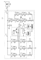
- the rotating electrical machine unit 16 includes a rotating electrical machine 21, an inverter 22, a field circuit 23, and a rotating electrical machine ECU 24 that controls the operation of the rotating electrical machine 21.
- the rotating electrical machine unit 16 is a generator with a motor function, and is configured as an electromechanically integrated ISG (Integrated / Starter / Generator). Details of the rotating electrical machine unit 16 will be described later.
- the battery unit U is provided with an electrical path L1 that connects the output terminals P1 and P2 and an electrical path L2 that connects the point N1 on the electrical path L1 and the lithium ion storage battery 12 as an in-unit electrical path.
- the switch 31 is provided in the electrical path L1
- the switch 32 is provided in the electrical path L2.
- the battery unit U is provided with a bypass path L3 that bypasses the switch 31.
- the bypass path L3 is provided so as to connect the output terminal P3 and the point N1 on the electrical path L1.
- the output terminal P3 is connected to the lead storage battery 11 via the fuse 35.
- a bypass switch 36 composed of a normally closed mechanical relay is provided in the bypass path L3, for example. By turning on (closing) the bypass switch 36, the lead storage battery 11, the electrical load 15, and the rotating electrical machine unit 16 are electrically connected even when the switch 31 is turned off (opened).
- the battery unit U includes a battery ECU 37 that controls on / off (opening / closing) of the switches 31 and 32.
- the battery ECU 37 is constituted by a microcomputer including a CPU, a ROM, a RAM, an input / output interface, and the like.
- the battery ECU 37 controls the on / off of the switches 31 and 32 based on the storage state of each of the storage batteries 11 and 12 and the command value from the engine ECU 40 that is the host controller. Thereby, charging / discharging is implemented using the lead storage battery 11 and the lithium ion storage battery 12 selectively.
- the battery ECU 37 calculates the SOC (State Of Charge) of the lithium ion storage battery 12 and controls the charge amount and discharge amount of the lithium ion storage battery 12 so that the SOC is maintained within a predetermined use range.
- SOC State Of Charge
- the rotating electrical machine ECU 24 of the rotating electrical machine unit 16 and the battery ECU 37 of the battery unit U are connected to an engine ECU 40 as a host controller that manages the ECUs 24 and 37 in an integrated manner.
- the engine ECU 40 is composed of a microcomputer including a CPU, ROM, RAM, input / output interface, and the like, and controls the operation of the engine 42 based on the engine operating state and the vehicle traveling state each time.
- Each of the ECUs 24, 37, 40 and other various in-vehicle ECUs (not shown) are connected to each other via a communication line 41 that constructs a communication network such as a CAN and can communicate with each other, and bidirectional communication is performed at a predetermined cycle. Is done. Thereby, the various data memorize
- the rotating electrical machine 21 is a three-phase AC motor (synchronous machine) and includes U-phase, V-phase, and W-phase phase windings 25U, 25V, and 25W as a three-phase armature winding 25, and a field winding 26. ing. Each phase winding 25U, 25V, 25W corresponds to an armature winding group. Each phase winding 25U, 25V, 25W is star-connected and connected to each other at a neutral point.
- the rotating shaft of the rotating electrical machine 21 is drivingly connected to an engine output shaft (not shown) by a belt, and the rotating shaft of the rotating electrical machine 21 is rotated by the rotation of the engine output shaft.
- the engine output shaft rotates. That is, the rotating electrical machine 21 has a power generation function that generates power (regenerative power generation) by rotating the engine output shaft and the axle, and a power running function that applies rotational force to the engine output shaft. For example, the rotating electrical machine 21 is driven by powering at the time of engine restart in idling stop control or power assist for vehicle acceleration.
- the inverter 22 converts the AC voltage output from each phase winding 25U, 25V, 25W into a DC voltage and outputs it to the battery unit U.
- the inverter 22 converts the DC voltage input from the battery unit U into an AC voltage and outputs the AC voltage to the phase windings 25U, 25V, and 25W.
- the inverter 22 is a bridge circuit having the same number of upper and lower arms as the number of phases of the phase winding, and constitutes a three-phase full-wave rectifier circuit.
- the inverter 22 constitutes a drive circuit that drives the rotating electrical machine 21 by adjusting the electric power supplied to the rotating electrical machine 21.
- the inverter 22 includes an upper arm switch Sp and a lower arm switch Sn for each phase.
- the switches Sp and Sn of each phase are alternately turned on and off, time-series energization is performed for each phase.
- voltage controlled semiconductor switching elements are used as the switches Sp and Sn, and specifically, N-channel MOSFETs are used.
- An upper arm diode Dp is connected in antiparallel to the upper arm switch Sp, and a lower arm diode Dn is connected in antiparallel to the lower arm switch Sn. That is, each of the diodes Dp and Dn is provided in such a direction that the cathode is the power supply side and the anode is the ground side.
- parasitic diodes of the switches Sp and Sn are used as the diodes Dp and Dn.
- the diodes Dp and Dn are not limited to parasitic diodes, and may be diodes that are separate from the switches Sp and Sn, for example.
- An intermediate point of the series connection body of the switches Sp and Sn in each phase is connected to one end of each phase winding 25U, 25V, and 25W.
- the inverter 22 is provided with a current detector 29 that detects the phase currents Iu, Iv, and Iw in the current path for each phase.
- the current detection unit 29 has a configuration including, for example, a shunt resistor and a current transformer.
- the field circuit 23 energizes the field winding 26 in accordance with on / off of a plurality of switching elements.
- the field circuit 23 includes one cutoff switch 50 and four field switches 51, 52, 53, and 54, and the field switches 51 to 54 constitute an H-bridge rectifier circuit.
- the basic configuration of each of the switches 50 to 54 is the same as that of each switch of the inverter 22, and a diode Di is connected to the semiconductor switching element in antiparallel.
- the field switches 51 and 52 are connected in series between the power supply unit (battery unit U in FIG. 2) and the ground, and the field switches 53 and 54 are connected between the power supply unit and the ground. Are connected in series. Then, the high side of the field switches 51 and 53, the intermediate points of the field switches 51 and 52 and the field switches 53 and 54, and the low side of the field switches 52 and 54 are electrically connected to each other.
- the field switches 51 to 54 are connected in an H bridge shape. In this case, the field switch 53 is provided in parallel with the field switch 51, and the field switch 54 is provided in parallel with the field switch 52.
- the field switches 51 to 54 are also referred to as a first switch 51, a second switch 52, a third switch 53, and a fourth switch 54, respectively.
- the field winding 26 is provided in a path portion connecting the intermediate point of the field switches 51 and 52 and the intermediate point of the field switches 53 and 54.
- the field winding 26 is connected to both ends of the second switch 52 and is provided in a parallel path section that is in parallel with the second switch 52.
- One of both ends of the field winding 26 is connected to an F + terminal that is an intermediate point between the field switches 51 and 52, and the other is connected to an F ⁇ terminal that is an intermediate point between the field switches 53 and 54.
- the F + terminal is a power supply side terminal (high side terminal), and the F ⁇ terminal is a ground side terminal (low side terminal).
- the field winding 26 is connected to the F + terminal and the F ⁇ terminal via a brush (not shown).
- FIG. 3 shows an energization path in the field circuit 23.
- the cutoff switch 50 is always on (fixed on)
- the third switch 53 is always off (fixed off)
- the fourth switch 54 is always on ( On-fixed).
- the first switch 51 and the second switch 52 are turned on and off in a conflicting period. In this case, when the first switch 51 is turned on and the second switch 52 is turned off, as shown by a broken line in FIG.
- a field current detector 55 for detecting a field current If flowing in the field winding 26 is provided on the ground side of the electric path at both ends of the fourth switch 54.
- a return current detection unit 56 that detects the return current Ir that flows while the first switch 51 is off and the second switch 52 is on is provided. ing. If the direction from the power supply side to the ground is positive, the field current If is detected as a positive current, and the return current Ir is detected as a negative current.
- the current detection units 55 and 56 have a configuration including, for example, a shunt resistor and a current transformer.
- a voltage sensor 45 that detects an input / output voltage (that is, a power supply voltage) of the inverter 22 is provided on the high-voltage side path of the inverter 22. Detection signals of the sensors including the voltage sensor 45 are appropriately input to the rotating electrical machine ECU 24.
- Each switch constituting the inverter 22 and the field circuit 23 is independently switched on / off via a driver 27.
- the rotating electrical machine ECU 24 is configured by a microcomputer including a CPU, a ROM, a RAM, an input / output interface, and the like.
- the rotating electrical machine ECU 24 adjusts the excitation current flowing through the field winding 26 by an IC regulator (not shown) inside. Thereby, the power generation voltage (output voltage with respect to the battery unit U) of the rotating electrical machine unit 16 is controlled.
- the rotating electrical machine ECU 24 controls on / off of the switches Sp and Sn of each phase according to the energization phase, and controls the energization current by adjusting the on / off ratio (for example, duty ratio) when energizing each phase.
- the rotating electrical machine ECU 24 assists the driving force of the engine by controlling the inverter 22 to drive the rotating electrical machine 21 after the vehicle starts running.
- the rotating electrical machine 21 can apply initial rotation to the crankshaft when starting the engine, and also has a function as an engine starting device.
- the rotating electrical machine ECU 24 calculates an energization current command value based on the power running torque command value and the generated voltage command value from the engine ECU 40, which is the host controller, and the energization current command value and the actual energization current (current detection unit 29).
- the operation signal is generated as a duty signal for energization current control for each phase based on the deviation from the detected current value).
- the command voltage is calculated for each phase based on the deviation between the energized current command value and the detected current value, and the operation is performed by PWM processing based on the magnitude comparison between the command voltage and a carrier signal (for example, a triangular wave signal).
- a signal for example, a triangular wave signal.
- the operation signal is generated by three-phase modulation, but pulse width modulation using a third-order harmonic superposition pattern can also be performed.
- the rotating electrical machine ECU 24 turns on and off the upper arm switch Sp and the lower arm switch Sn for each phase according to the operation signal of each phase. Thereby, each phase current of the rotating electrical machine 21 is feedback-controlled.
- the above-described PWM control may be performed in a rotation range that is a predetermined rotation speed or less.
- rectangular wave control control that is turned on / off at the zero cross point of the target voltage
- the rotating electrical machine ECU 24 calculates a field current command value based on the power running torque command value and the generated voltage command value from the engine ECU 40, and the field current command value and the actual field current (field current detection unit).
- the operation signal is generated as a duty signal for field current control based on the deviation from the current detection value of 55).
- the command voltage is calculated based on the deviation between the field current command value and the detected current value, and the operation signal (PWM signal) is generated by PWM processing based on the magnitude comparison between the command voltage and the carrier signal.
- PWM signal is generated by PWM processing based on the magnitude comparison between the command voltage and the carrier signal.
- the driver 27 charges and discharges the gate terminals (conduction control terminals) of the switching elements constituting the switches Sp and Sn of the inverter 22 and the switches 51 to 54 of the field circuit 23, and turns on the switching elements. It is the drive device which switches between a state and an off state.
- the configuration of the driver 27 will be described by taking the switch Sp as an example.
- the driver 27 includes a resistor 62 and a charging switch 63 connected to a power source 61 as a charging circuit.
- a charging switch 63 When the charging switch 63 is turned on, a constant current flows through the gate of the switch Sp, and the switch 27 Sp gate charging is performed. As a result, the switch Sp is turned on.
- the driver 27 has two discharge parts as a discharge circuit, one of which is a first discharge part 64 for normal interruption by an operation signal, and the other is a second discharge part 65 for soft interruption. It has become.
- the first discharge unit 64 includes a first discharge resistor 66 and a first discharge switch 67
- the second discharge unit 65 includes a second discharge resistor 68 and a second discharge switch 69.
- the first discharge resistor 66 and the second discharge resistor 68 have different resistance values, and the resistance value R1 of the first discharge resistor 66 and the resistance value R2 of the second discharge resistor 68 satisfy R1 ⁇ R2. It has become a relationship.
- These discharge resistors 66 and 68 are resistors for adjusting the discharge speed (cutoff speed). From the relationship of R1 ⁇ R2, the second discharge is more effective than the case where the gate discharge is performed via the first discharge switch 67. When the gate discharge is performed through the switch 69, the discharge rate is slower.
- the switch Sp is turned off (cut off)
- the first discharge switch 67 and the second discharge switch 69 are alternatively turned on, and the first discharge switch 67 is turned on.
- the normal interruption is performed
- the second discharge switch 69 is turned on, so that the soft interruption with the interruption speed slower than the normal interruption is performed.
- the charging switch 63 and the first discharging switch 67 are turned on / off based on an operation signal from the rotating electrical machine ECU 24.
- an upper arm switch Sp and a lower arm switch Sn are provided as a pair of switches that are a series connection body.
- a first pair of switches that are a series connection body is provided in the field circuit 23 .
- a first switch 51 and a second switch 52 are provided in the field circuit 23 .
- Each of the pair of switches is alternately turned on and off by an operation signal.
- the switch is cut off.
- the switch is cut off in a state where a large current flows, there is a concern that the switch is broken due to a surge voltage.
- the switch in a state where a large current is flowing, the switch is turned off by the soft cutoff.
- the ON time of the operation signal is too short, the overcurrent determination and the accompanying switch interruption operation are not performed properly, and there is a concern that a large current interruption may be performed as a result.
- the ON time of the operation signal is limited so that at least the time required for the overcurrent determination and the interruption operation start is secured.
- a shut-off operation unit 72 for softly shutting off the switches.
- the determination unit 71 is configured using, for example, a comparator.
- the determination unit 71 and the shut-off operation unit 72 are realized by, for example, an ASIC 70 that is a dedicated IC circuit.
- the rotary electric machine ECU 24 and the ASIC 70 constitute a “switch control device”.
- the determination unit 71 inputs the current detection value detected by the current detection unit 29, and based on the current detection value exceeding a predetermined threshold, It is determined that an overcurrent has flowed. Based on the determination result of the determination unit 71, the cutoff operation unit 72 outputs a command signal for turning on the second discharge switch 69 to the soft discharge second discharge unit 65 in the driver 27. As a result, the soft cutoff is performed for the switch on the side where the ON failure has not occurred among the upper arm switch Sp and the lower arm switch Sn.
- the determination unit 71 inputs the current detection value detected by the return current detection unit 56, and the current detection value exceeds a predetermined threshold value. Based on this, it is determined that an overcurrent has flowed. Based on the determination result of the determination unit 71, the cutoff operation unit 72 outputs a command signal for turning on the second discharge switch 69 to the soft discharge second discharge unit 65 in the driver 27. Thereby, soft interruption
- the second switch 52 can be used to properly perform overcurrent determination and soft interruption. It is necessary to secure the minimum necessary time as the on-time in. Therefore, an upper limit guard for the duty ratio is performed on the operation signal of the first switch 51. This upper limit guard is performed by a duty upper limit value having a duty ratio smaller than 100%. By this upper limit guard, the operation signal of the second switch 52 becomes a signal having a duty ratio larger than 0%. Further, assuming an on-failure that occurs in the second switch 52, it is necessary to secure a minimum necessary time as the on-time in the first switch 51 in order to properly perform overcurrent determination and soft interruption.
- a lower limit guard of the duty ratio is performed on the operation signal of the first switch 51.
- This lower limit guard is performed by a duty lower limit value having a duty ratio larger than 0%.
- the operation signal of the second switch 52 becomes a signal having a duty ratio smaller than 100%.
- FIG. 5 is a flowchart showing a processing procedure of operation signal generation performed by the rotating electrical machine ECU 24, and this processing is repeatedly performed at a predetermined cycle.
- the operation signal for controlling the field current will be described as an example.
- step S11 a PWM signal is generated by PWM processing based on the power running torque command value and the generated voltage command value.
- step S12 it is determined whether or not the PWM duty ratio of the first switch 51 of the first switch 51 and the second switch 52 exceeds a predetermined upper limit value.
- step S14 it is determined whether the PWM duty ratio of the first switch 51 of the first switch 51 and the second switch 52 is less than a predetermined lower limit value.
- the lower limit is, for example, 5%.
- step S16 an operation signal is generated and output based on the PWM duty ratio that has been limited as described above or the PWM duty ratio that has not been limited.
- the operation limit for the first switch is limited by the duty upper limit value.
- the duty lower limit is set for the operation signal for the second switch. Agree to enforce value restrictions.
- the restriction by the duty lower limit value for the operation signal for the first switch is the same as the restriction by the duty upper limit value for the operation signal for the second switch.
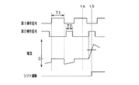
- FIG. 6 is a time chart showing the switching operation of the first switch 51 and the second switch 52 in the field circuit 23.
- the first operation signal for the first switch and the second operation signal for the second switch are alternately turned on and off and have a predetermined dead time.
- the carrier signal is 1 kHz, for example, and the PWM cycle determined by the carrier signal is 1 msec.
- the first switch 51 is turned on during the on period T1 of the first operation signal
- the second switch 52 is turned on during the on period T2 of the second operation signal.
- FIG. 6 shows the transition of the current detected by the return current detection unit 56, and this current is detected as a negative current during the period when the first switch 51 is turned off.
- the determination unit 71 performs overcurrent determination. For example, it takes about 10 ⁇ sec to determine that an overcurrent has flowed.
- the cutoff operation unit 72 When it is determined in the determination unit 71 that an overcurrent has flowed, the cutoff operation unit 72 performs soft cutoff on either the first switch 51 or the second switch 52 based on the determination result. At this time, the upper limit guard of the duty ratio of the first operation signal is implemented assuming the ON failure of the first switch 51. Conversely, the lower limit guard of the duty ratio of the second operation signal is implemented. Thus, the overcurrent determination and the switch breaking operation are appropriately performed in the ON period of the second switch 52. At this time, for example, at least 20 ⁇ sec is preferably secured as the ON time of the second switch 52.
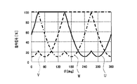
- energization current control using two-phase modulation may be performed.
- the rotating electrical machine ECU 24 sequentially fixes the operation states of the upper arm switch Sp and the lower arm switch Sn of each phase one phase at a predetermined period, and configures two phases other than the fixed phase.
- the upper arm switch Sp and the lower arm switch Sn are turned on / off by PWM processing.
- the upper arm switch Sp is turned off and the lower arm switch Sn is turned on and off one by one for each electrical angle of 120 ° of the rotating electrical machine 21.
- a command signal for each phase (a feedforward operation amount calculated according to the energization current command value for each phase and the electrical angular velocity of the rotating electrical machine 21) is set. Based on this command signal, an operation signal is generated for each phase.
- a two-phase command signal for fixing the operation state may be set so that the interphase voltage becomes a sine wave. In this case, on the assumption that the maximum value of the carrier signal is “1” and the minimum value is “0”, the command signal of the upper arm switch Sp fixed to the off operation is fixed to the lower limit value and fixed to the on operation. The command signal of the lower arm switch Sn is fixed to the upper limit value.
- each phase command so that the upper arm switch Sp is turned on and the lower arm switch Sn is turned on and off one by one for each electrical angle of 120 ° of the rotating electrical machine 21.
- the signal is set. Based on this command signal, an operation signal is generated for each phase.
- the command signal of the upper arm switch Sp that is fixed to the ON operation is fixed to the upper limit value
- the command signal of the lower arm switch Sn that is fixed to the ON operation is fixed to the upper limit value.
- the on time of the operation signal for turning on and off the pair of switches in the rotating electrical machine 21 is configured to limit at least the time required for the overcurrent determination by the determination unit 71 and the start of the interruption operation by the interruption operation unit 72.
- the operation signal for the first switch 51 is limited by the duty upper limit value, thereby causing an overcurrent to flow due to the ON failure of the first switch 51.
- the operation signal for the first switch 51 by the duty lower limit value, it is assumed that an overcurrent flows due to an ON failure of the second switch 52, and then the first switch 51 is turned on. Overcurrent determination and switch-off operation can be performed properly within the period.
- the frequency f1 of the carrier signal used for generating the operation signal used for the on / off control of the armature winding 25 and the carrier signal used for generating the operation signal used for the on / off control of the field winding 26 It is conceivable that the frequency f2 is different from each other. For example, it can be considered that f1> f2 or f1 ⁇ f2. Further, it is conceivable to vary the frequency f1 of the carrier signal used for generating the operation signal for armature control, or to vary the frequency f2 of the carrier signal used for generating the operation signal for field control.
- the duty limit value is determined according to the frequency of the carrier signal and limit the duty ratio of the operation signal by the duty limit value. For example, the duty upper limit value is decreased as the frequency of the carrier signal is increased. Further, the duty lower limit value is increased as the frequency of the carrier signal is increased.
- the frequency f1 of the carrier signal used to generate the operation signal for armature control (inverter control) and the frequency f2 of the carrier signal used to generate the operation signal for field control have a relationship of f1> f2.
- the difference in duty limit value is shown.
- the duty limit value is different between the armature control and the field control. Specifically, in the armature control on the high frequency side, the duty upper limit value is smaller and the duty lower limit value is larger than in the field control on the low frequency side.
- the field circuit 23 is configured with an H-bridge circuit, but the field circuit 23 may be configured with a half-bridge circuit instead.
- FIG. 10 shows a field circuit 23 having a half-bridge circuit configuration.
- a first switch 51 and a second switch 52 are connected in series between the power supply unit and the ground, and the field winding 26 is provided in a parallel path portion in parallel with the second switch 52. Is provided. Also in this configuration, the duty ratio of the operation signal (duty signal) may be limited as described above.
- the application example to the three-phase AC motor as the rotating electrical machine 21 has been described, but this may be changed.
- it can be applied to a six-phase AC motor having two sets of three-phase armature winding groups.
- it can be applied to an AC motor having n sets of three-phase armature winding groups (n is 1 or more).
- the rotating electrical machine that performs the power generation operation and the power running operation has been described, but the present invention can also be applied to a rotating electrical machine that performs only the power generation operation or the power running operation.
- the power supply system to which the present disclosure is applied can also be used for uses other than vehicles, for example, for ships, aircraft, robots, and the like.
- each said component is conceptual and is not limited to the said embodiment.
- the functions of one component may be realized by being distributed to a plurality of components, or the functions of a plurality of components may be realized by one component.
Abstract
Switch control devices (24, 70) turn a pair of switches (Sp, Sn, 51, 52) on and off alternately according to a duty signal, so that both are not on simultaneously. The switches (Sp, Sn, 51, 52) are provided in series between a power supply unit and a ground. The switch control device comprises: a signal generating unit (24) that generates duty signals; a determination unit (71) that determines that overcurrent is flowing in a route passing through the pair of switches, in a state for which after an on failure has occurred with one switch of the pair of switches, the other switch is turned on; a break operation unit (72) that, when it is determined by the determination unit that overcurrent is flowing, breaks at a slower speed than the normal break speed of the other switch; and a restriction unit (24) that restricts the on time of the duty signal so as to ensure at least the time required for overcurrent determination by the determination unit and starting of the break operation by the break operation unit.
Description
本出願は、2017年1月31日に出願された日本出願番号2017-016080号に基づくもので、ここにその記載内容を援用する。
This application is based on Japanese Application No. 2017-016080 filed on Jan. 31, 2017, the contents of which are incorporated herein by reference.
本開示は、電源部とグランドとの間に直列に設けられた一対のスイッチをオンオフさせるスイッチ制御装置に関するものである。
This disclosure relates to a switch control device that turns on and off a pair of switches provided in series between a power supply unit and a ground.
従来、回転電機(交流モータ)について異常の有無を判定し、異常発生時にはその異常に応じた対応処置を実施する技術が知られている。例えば特許文献1には、電力変換装置の電流と電流変化量とに応じた判定用電圧値を検出し、判定用電圧値が第1判定閾値を上回った場合に、電力変換の運転停止を指示する一方、判定用電圧値が第1判定閾値よりも大きい第2判定閾値を上回った場合に、電力変換の運転停止後において電力変換の運転再開を制限する技術が開示されている。
Conventionally, there has been known a technique for determining whether or not there is an abnormality in a rotating electric machine (AC motor) and performing a countermeasure corresponding to the abnormality when the abnormality occurs. For example, Patent Document 1 detects a voltage value for determination according to the current of the power conversion device and the amount of current change, and instructs to stop the operation of power conversion when the voltage value for determination exceeds a first determination threshold value. On the other hand, a technique is disclosed that restricts restarting of power conversion after the power conversion operation is stopped when the determination voltage value exceeds a second determination threshold value that is larger than the first determination threshold value.
ところで、インバータ等の電力変換装置では一般に、電源部とグランドとの間に直列に電流制御用の一対の半導体スイッチを接続し、その一対の半導体スイッチを互い違いにオンオフさせる構成が用いられる。かかる構成では、一対の半導体スイッチのうち一方がオン故障することに伴い一対の半導体スイッチを通じて過大な電流(貫通電流)が流れることが考えられるため、過電流が流れたと判定されると、その判定に応じてスイッチを遮断させる処置が行われる。
By the way, a power conversion device such as an inverter generally uses a configuration in which a pair of semiconductor switches for current control are connected in series between a power supply unit and a ground, and the pair of semiconductor switches are alternately turned on and off. In such a configuration, it is considered that an excessive current (through current) flows through the pair of semiconductor switches when one of the pair of semiconductor switches is turned on, so when it is determined that an overcurrent has flowed, the determination In response to this, the switch is turned off.
ここで、過電流の判定にはある程度の時間を要する。そのため、過電流が流れ始めてから過電流判定が完了するまでの間に、半導体スイッチが通常操作として遮断されることがあり得る。かかる場合、そのスイッチ遮断に伴い、大電流遮断による半導体スイッチのサージ破壊が生じることが懸念される。
Here, it takes a certain amount of time to determine overcurrent. For this reason, the semiconductor switch may be interrupted as a normal operation after the overcurrent starts to flow until the overcurrent determination is completed. In such a case, there is a concern that surge destruction of the semiconductor switch due to large current interruption may occur with the switch interruption.
本開示は、上記課題に鑑みてなされたものであり、その主たる目的は、一対のスイッチを含む経路での過電流発生時において適正にスイッチ遮断を実施することができるスイッチ制御装置を提供することにある。
This indication is made in view of the above-mentioned subject, and the main purpose is to provide a switch control device which can perform switch interception appropriately at the time of overcurrent generation in a course containing a pair of switches. It is in.
以下、上記課題を解決するための手段、及びその作用効果について説明する。
Hereinafter, the means for solving the above-mentioned problems and the effects thereof will be described.
第1の手段では、
電源部とグランドとの間に直列に設けられた一対のスイッチを、両方が同時にオンしないようにしてデューティ信号により互い違いにオンオフさせるスイッチ制御装置であって、
前記デューティ信号を生成する信号生成部と、
前記一対のスイッチのうち一方のスイッチのオン故障が生じた後に他方のスイッチがオンした状態で、前記一対のスイッチに通じる経路で過電流が流れたことを判定する判定部と、
前記判定部により前記過電流が流れたと判定された場合に、前記他方のスイッチを通常の遮断速度よりも遅い速度で遮断させる遮断操作部と、
少なくとも前記判定部による過電流判定と前記遮断操作部による遮断操作開始とに要する時間が確保されるように前記デューティ信号のオン時間を制限する制限部と、を備える。 In the first means,
A switch control device that alternately turns on and off a pair of switches provided in series between a power supply unit and a ground by a duty signal so that both are not simultaneously turned on,
A signal generator for generating the duty signal;
A determination unit that determines that an overcurrent has flowed in a path leading to the pair of switches in a state where the other switch is turned on after an on failure of one of the pair of switches occurs;
When it is determined by the determination unit that the overcurrent has flowed, a shut-off operation unit that shuts off the other switch at a speed slower than a normal shut-off speed;
A limiting unit that limits the on-time of the duty signal so as to secure at least the time required for the overcurrent determination by the determination unit and the start of the cutoff operation by the cutoff operation unit.
一対のスイッチのうち一方のスイッチのオン故障が生じた後に他方のスイッチがオンすると、一対のスイッチに過大な電流(貫通電流)が流れる。また、大電流が流れている状態でスイッチを遮断すると、サージ電圧によるスイッチ破壊が懸念される。そのため、大電流が流れている状態では、通常の遮断速度よりも遅い速度でスイッチ遮断(いわゆるソフト遮断)が行われるとよい。ただし、デューティ信号によりオンオフされる各スイッチにおいて、そのオン時間が短すぎると、過電流判定とそれに伴うスイッチ遮断操作とが適正に行われず、結果として大電流遮断が行われることが懸念される。
When an on failure of one of the pair of switches occurs and the other switch is turned on, an excessive current (through current) flows through the pair of switches. Further, if the switch is shut off in a state where a large current is flowing, there is a concern that the switch is broken due to a surge voltage. Therefore, in a state where a large current is flowing, it is preferable that the switch cutoff (so-called soft cutoff) is performed at a speed slower than the normal cutoff speed. However, in each switch that is turned on / off by the duty signal, if the on-time is too short, the overcurrent determination and the accompanying switch-off operation are not properly performed, and as a result, there is a concern that a large current is cut off.
この点、上記構成では、少なくとも判定部による過電流判定と遮断操作部による遮断操作開始とに要する時間が確保されるようにデューティ信号のオン時間が制限されるようになっている。これにより、一方のスイッチがオン故障した場合において、過電流を適正に判定するとともに、その過電流が流れている状態でのスイッチ遮断(ソフト遮断)を適正に実施することができる。その結果、一対のスイッチを含む経路での過電流発生時において適正にスイッチ遮断を実施し、ひいてはスイッチの保護を図ることができる。
In this regard, in the above configuration, the on-time of the duty signal is limited so that at least the time required for the overcurrent determination by the determination unit and the start of the cutoff operation by the cutoff operation unit is secured. As a result, when one of the switches is on-failed, it is possible to appropriately determine the overcurrent and appropriately perform the switch cutoff (soft cutoff) in the state where the overcurrent flows. As a result, when an overcurrent occurs in a path including a pair of switches, the switch can be properly cut off, and thus the switch can be protected.
第2の手段では、巻線界磁型の回転電機の界磁巻線を通電させる界磁回路を有する回転電機ユニットに適用され、前記界磁回路は、前記一対のスイッチとして電源部側の第1界磁スイッチとグランド側の第2界磁スイッチとを有しており、前記判定部は、前記第1界磁スイッチ及び前記第2界磁スイッチを通じて前記過電流が流れたことを判定し、前記制限部は、前記第1界磁スイッチをオンオフする前記デューティ信号についてデューティ上限値による制限、及び当該デューティ信号についてデューティ下限値による制限の少なくともいずれかを実施する。
The second means is applied to a rotating electrical machine unit having a field circuit for energizing a field winding of a wound field type rotating electrical machine, and the field circuit is used as a pair of switches on the power supply side. A first field switch and a second field switch on the ground side, and the determination unit determines that the overcurrent flows through the first field switch and the second field switch, The restriction unit performs at least one of restriction by a duty upper limit value for the duty signal for turning on and off the first field switch and restriction by a duty lower limit value for the duty signal.
巻線界磁型回転電機の界磁回路では、界磁電流制御において第1界磁スイッチ及び第2界磁スイッチが互い違いにオンオフされる。この場合、第1界磁スイッチ用のデューティ信号についてデューティ上限値による制限を実施することにより、第1界磁スイッチのオン故障に起因して過電流が流れることを想定した上で、第2界磁スイッチのオン期間内において過電流判定とスイッチ遮断操作とを適正に実施できる。又は、第1界磁スイッチ用のデューティ信号についてデューティ下限値による制限を実施することにより、第2界磁スイッチのオン故障に起因して過電流が流れることを想定した上で、第1界磁スイッチのオン期間内において過電流判定とスイッチ遮断操作とを適正に実施できる。
In the field circuit of the wound field type rotary electric machine, the first field switch and the second field switch are alternately turned on and off in the field current control. In this case, by limiting the duty signal for the first field switch by the duty upper limit value, it is assumed that an overcurrent flows due to an ON failure of the first field switch, and then the second field switch. Overcurrent determination and switch shut-off operation can be performed properly within the on-period of the magnetic switch. Alternatively, by limiting the duty signal for the first field switch by the duty lower limit value, it is assumed that an overcurrent flows due to an ON failure of the second field switch, and then the first field switch. Overcurrent determination and switch cutoff operation can be properly performed within the switch ON period.
なお、第1界磁スイッチ及び第2界磁スイッチが互い違いにオンオフされる構成からすると、第1界磁スイッチ用のデューティ信号についてデューティ上限値による制限を実施することは、第2界磁スイッチ用のデューティ信号についてデューティ下限値による制限を実施することと同意である。また同様に、第1界磁スイッチ用のデューティ信号についてデューティ下限値による制限を実施することは、第2界磁スイッチ用のデューティ信号についてデューティ上限値による制限を実施することと同意である。なお、デューティ上限値は、デューティ比100%よりも小さい値、デューティ下限値はデューティ比0%よりも大きい値である。これらは後述の手段3についても同様である。
If the first field switch and the second field switch are alternately turned on and off, the duty field limit for the first field switch duty signal is limited to the second field switch. It is agreed that the duty signal is limited by the duty lower limit value. Similarly, the restriction by the duty lower limit value for the duty signal for the first field switch is equivalent to the restriction by the duty upper limit value for the duty signal for the second field switch. The duty upper limit value is a value smaller than the duty ratio 100%, and the duty lower limit value is a value larger than the duty ratio 0%. The same applies to the means 3 described later.
第3の手段では、3相の電機子巻線群を有する回転電機と、前記回転電機の各相の電機子巻線を相ごとに通電させるインバータ回路を有する回転電機ユニットに適用され、前記インバータ回路は、前記一対のスイッチとして相ごとに上アームスイッチと下アームスイッチとを有しており、前記判定部は、前記上アームスイッチ及び前記下アームスイッチを通じて前記過電流が流れたことを判定し、前記制限部は、前記上アームスイッチをオンオフする前記デューティ信号についてデューティ上限値による制限、及び当該デューティ信号についてデューティ下限値による制限の少なくともいずれかを実施する。
The third means is applied to a rotating electrical machine unit having a rotating electrical machine having a three-phase armature winding group and an inverter circuit for energizing each phase of the armature winding of the rotating electrical machine for each phase. The circuit includes an upper arm switch and a lower arm switch for each phase as the pair of switches, and the determination unit determines that the overcurrent flows through the upper arm switch and the lower arm switch. The restriction unit performs at least one of restriction by a duty upper limit value for the duty signal for turning on and off the upper arm switch and restriction by a duty lower limit value for the duty signal.
回転電機のインバータ回路では、各相の通電電流制御において上アームスイッチ及び下アームスイッチが互い違いにオンオフされる。この場合、上アームスイッチ用のデューティ信号についてデューティ上限値による制限を実施することにより、上アームスイッチのオン故障に起因して過電流が流れることを想定した上で、下アームスイッチのオン期間内において過電流判定とスイッチ遮断操作とを適正に実施できる。又は、上アームスイッチ用のデューティ信号についてデューティ下限値による制限を実施することにより、下アームスイッチのオン故障に起因して過電流が流れることを想定した上で、上アームスイッチのオン期間内において過電流判定とスイッチ遮断操作とを適正に実施できる。
In the inverter circuit of a rotating electrical machine, the upper arm switch and the lower arm switch are alternately turned on and off in the current control of each phase. In this case, by limiting the duty signal for the upper arm switch by the duty upper limit value, it is assumed that an overcurrent will flow due to an on failure of the upper arm switch, and then within the on period of the lower arm switch. Thus, it is possible to properly carry out overcurrent determination and switch breaking operation. Or, by limiting the duty signal for the upper arm switch by the duty lower limit value, it is assumed that an overcurrent flows due to an on failure of the lower arm switch, and within the on period of the upper arm switch. Overcurrent determination and switch cutoff operation can be performed properly.
第4の手段では、回転電機の電機子巻線及び界磁巻線の少なくともいずれかに繋がる通電経路に前記一対のスイッチが設けられ、その一対のスイッチのオンオフを制御するスイッチ制御装置であって、前記デューティ信号は、前記電機子巻線及び前記界磁巻線の少なくともいずれかへの通電電流の要求値に応じて算出される指令信号と、所定周波数のキャリア信号との比較に基づいて生成され、前記制限部は、前記キャリア信号の周波数に応じて定められるデューティ制限値により、前記デューティ信号のデューティ比を制限する。
According to a fourth means, the switch control device is provided with the pair of switches in an energization path connected to at least one of the armature winding and the field winding of the rotating electric machine, and controls on / off of the pair of switches. The duty signal is generated on the basis of a comparison between a command signal calculated according to a required value of an energization current to at least one of the armature winding and the field winding and a carrier signal having a predetermined frequency. The limiting unit limits the duty ratio of the duty signal by a duty limit value determined according to the frequency of the carrier signal.
回転電機では、例えば、電機子制御用のデューティ信号を生成する際に用いるキャリア信号の周波数と、界磁制御用のデューティ信号を生成する際に用いるキャリア信号の周波数とが互いに異なることが考えられる。また、電機子制御用のデューティ信号を生成する際に用いるキャリア信号の周波数を可変にすること、又は、界磁制御用のデューティ信号を生成する際に用いるキャリア信号の周波数を可変にすることが考えられる。この点を考慮し、キャリア信号の周波数に応じて定められるデューティ制限値により、デューティ信号のデューティ比を制限するとよい。これにより、過電流判定とスイッチ遮断操作との所要時間を確保しつつ、適度なオン時間の制限を実現できる。例えば、キャリア信号の周波数が大きいほどデューティ上限値を小さくする。また、キャリア信号の周波数が大きいほどデューティ下限値を大きくする。
In a rotating electrical machine, for example, the frequency of a carrier signal used when generating a duty signal for armature control may be different from the frequency of a carrier signal used when generating a duty signal for field control. Also, it is conceivable to vary the frequency of the carrier signal used when generating the duty signal for armature control, or to vary the frequency of the carrier signal used when generating the duty signal for field control. . Considering this point, the duty ratio of the duty signal may be limited by a duty limit value determined according to the frequency of the carrier signal. As a result, it is possible to achieve an appropriate on-time limit while ensuring the time required for the overcurrent determination and the switch cutoff operation. For example, the duty upper limit value is decreased as the frequency of the carrier signal is increased. Further, the duty lower limit value is increased as the frequency of the carrier signal is increased.
第4の手段では、電機子巻線に繋がる通電経路、及び界磁巻線に繋がる通電経路にそれぞれ一対のスイッチが設けられ、それら各一対のスイッチのオンオフを制御するスイッチ制御装置において、電機子制御用のデューティ信号を生成する際に用いるキャリア信号の周波数と、界磁制御用のデューティ信号を生成する際に用いるキャリア信号の周波数とが相違していることが考えられる。かかる場合において、第5の手段にように、前記デューティ制限値が、前記電機子制御用のデューティ信号と、前記界磁制御用のデューティ信号とで各々異なる値として定められているとよい。
In the fourth means, a pair of switches are provided in each of the energization path connected to the armature winding and the energization path connected to the field winding, and in the switch control device for controlling on / off of each pair of switches, the armature It is conceivable that the frequency of the carrier signal used when generating the control duty signal is different from the frequency of the carrier signal used when generating the field control duty signal. In such a case, as in the fifth means, the duty limit value may be determined as a value different between the duty signal for armature control and the duty signal for field control.
本開示についての上記目的およびその他の目的、特徴や利点は、添付の図面を参照しながら下記の詳細な記述により、より明確になる。その図面は、
図1は、車両システムを示す電気回路図であり、
図2は、回転電機ユニットの電気的構成を示す回路図であり、
図3は、界磁回路における通電経路を示す回路図であり、
図4は、ドライバの構成を簡略に示す回路図であり、
図5は、操作信号生成の処理手順を示すフローチャートであり、
図6は、界磁回路における第1スイッチ及び第2スイッチのスイッチング動作を示すタイムチャートであり、
図7は、2相変調手法を説明するための図であり、
図8は、2相変調手法を説明するための図であり、
図9は、デューティ制限値を説明するための図であり、
図10は、ハーフブリッジ構成の界磁回路を示す回路図である。
The above and other objects, features and advantages of the present disclosure will become more apparent from the following detailed description with reference to the accompanying drawings. The drawing
FIG. 1 is an electric circuit diagram showing a vehicle system. FIG. 2 is a circuit diagram showing an electrical configuration of the rotating electrical machine unit. FIG. 3 is a circuit diagram showing energization paths in the field circuit, FIG. 4 is a circuit diagram schematically showing the configuration of the driver. FIG. 5 is a flowchart showing a processing procedure for generating an operation signal. FIG. 6 is a time chart showing the switching operation of the first switch and the second switch in the field circuit, FIG. 7 is a diagram for explaining the two-phase modulation method. FIG. 8 is a diagram for explaining the two-phase modulation method. FIG. 9 is a diagram for explaining the duty limit value. FIG. 10 is a circuit diagram showing a field circuit having a half-bridge configuration.
以下、実施形態を図面に基づいて説明する。本実施形態では、エンジン(内燃機関)を駆動源として走行する車両の各種機器に電力を供給する車両システムにおいて、当該システムの制御を実施する制御装置を具体化するものとしている。なお、以下の各実施形態相互において、互いに同一又は均等である部分には、図中、同一符号を付しており、同一符号の部分についてはその説明を援用する。
Hereinafter, embodiments will be described with reference to the drawings. In the present embodiment, in a vehicle system that supplies electric power to various devices of a vehicle that travels using an engine (internal combustion engine) as a drive source, a control device that performs control of the system is embodied. In the following embodiments, parts that are the same or equivalent to each other are given the same reference numerals in the drawings, and the description of the same reference numerals is used.
図1に示すように、車両システムは、電源部として鉛蓄電池11とリチウムイオン蓄電池12とを有する2電源システムである。各蓄電池11,12からは、スタータ13や、各種の電気負荷14,15、回転電機ユニット16への給電が可能となっている。また、各蓄電池11,12に対しては、回転電機ユニット16による充電が可能となっている。本システムでは、回転電機ユニット16及び電気負荷14,15のそれぞれに対して、鉛蓄電池11及びリチウムイオン蓄電池12が並列に接続されている。
As shown in FIG. 1, the vehicle system is a two-power supply system having a lead storage battery 11 and a lithium ion storage battery 12 as a power supply unit. Each storage battery 11, 12 can supply power to the starter 13, various electric loads 14, 15, and the rotating electrical machine unit 16. Further, each of the storage batteries 11 and 12 can be charged by the rotating electrical machine unit 16. In this system, a lead storage battery 11 and a lithium ion storage battery 12 are connected in parallel to the rotating electrical machine unit 16 and the electrical loads 14 and 15, respectively.
鉛蓄電池11は周知の汎用蓄電池である。リチウムイオン蓄電池12は、鉛蓄電池11に比べて、充放電における電力損失が少なく、出力密度、及びエネルギ密度の高い高密度蓄電池である。リチウムイオン蓄電池12は、鉛蓄電池11に比べて充放電時のエネルギ効率が高い蓄電池であることが望ましい。このリチウムイオン蓄電池12は、それぞれ複数の単電池を有してなる組電池として構成されている。これら各蓄電池11,12の定格電圧はいずれも同じであり、例えば12Vである。
The lead storage battery 11 is a well-known general-purpose storage battery. The lithium ion storage battery 12 is a high-density storage battery that has less power loss during charging / discharging and higher output density and energy density than the lead storage battery 11. The lithium ion storage battery 12 is desirably a storage battery having higher energy efficiency during charging / discharging than the lead storage battery 11. The lithium ion storage battery 12 is configured as an assembled battery having a plurality of single cells. These storage batteries 11 and 12 have the same rated voltage, for example, 12V.
リチウムイオン蓄電池12は、収容ケースに収容されて基板一体の電池ユニットUとして構成されている。電池ユニットUは、出力端子P1,P2,P3を有しており、このうち出力端子P1,P3に鉛蓄電池11とスタータ13と電気負荷14とが接続され、出力端子P2に電気負荷15と回転電機ユニット16とが接続されている。
The lithium ion storage battery 12 is housed in a housing case and configured as a battery unit U integrated with a substrate. The battery unit U has output terminals P1, P2 and P3, of which the lead storage battery 11, the starter 13 and the electric load 14 are connected to the output terminals P1 and P3, and the electric load 15 and the rotation are connected to the output terminal P2. The electric unit 16 is connected.
各電気負荷14,15は、各蓄電池11,12からの供給電力の電圧に対する要求が相違するものである。このうち電気負荷14には、供給電力の電圧が一定又は少なくとも所定範囲内で変動するよう安定であることが要求される定電圧要求負荷が含まれる。これに対し、電気負荷15は、定電圧要求負荷以外の一般的な電気負荷である。
The electric loads 14 and 15 have different requirements for the voltage of power supplied from the storage batteries 11 and 12. Among these, the electric load 14 includes a constant voltage required load that is required to be stable so that the voltage of the supplied power is constant or at least fluctuates within a predetermined range. On the other hand, the electric load 15 is a general electric load other than the constant voltage required load.
定電圧要求負荷である電気負荷14の具体例としては、ナビゲーション装置やオーディオ装置、メータ装置、エンジンECU等の各種ECUが挙げられる。この場合、供給電力の電圧変動が抑えられることで、上記各装置において不要なリセット等が生じることが抑制され、安定動作が確保される。電気負荷14として、電動ステアリング装置やブレーキ装置等の走行系アクチュエータが含まれていてもよい。電気負荷15の具体例としては、シートヒータやリヤウインドウのデフロスタ用ヒータ、ヘッドライト、フロントウインドウのワイパ、空調装置の送風ファン等が挙げられる。
Specific examples of the electric load 14 that is a constant voltage required load include various ECUs such as a navigation device, an audio device, a meter device, and an engine ECU. In this case, by suppressing the voltage fluctuation of the supplied power, it is possible to suppress the occurrence of unnecessary reset and the like in each of the above devices, and ensure stable operation. The electric load 14 may include a travel system actuator such as an electric steering device or a brake device. Specific examples of the electric load 15 include a seat heater, a heater for a defroster for a rear window, a headlight, a wiper for a front window, and a blower fan for an air conditioner.
回転電機ユニット16は、回転電機21と、インバータ22と、界磁回路23と、回転電機21の作動を制御する回転電機ECU24とを備えている。回転電機ユニット16は、モータ機能付き発電機であり、機電一体型のISG(Integrated Starter Generator)として構成されている。回転電機ユニット16の詳細については後述する。
The rotating electrical machine unit 16 includes a rotating electrical machine 21, an inverter 22, a field circuit 23, and a rotating electrical machine ECU 24 that controls the operation of the rotating electrical machine 21. The rotating electrical machine unit 16 is a generator with a motor function, and is configured as an electromechanically integrated ISG (Integrated / Starter / Generator). Details of the rotating electrical machine unit 16 will be described later.
電池ユニットUには、ユニット内電気経路として、各出力端子P1,P2を繋ぐ電気経路L1と、電気経路L1上の点N1とリチウムイオン蓄電池12とを繋ぐ電気経路L2とが設けられている。このうち電気経路L1にスイッチ31が設けられ、電気経路L2にスイッチ32が設けられている。
The battery unit U is provided with an electrical path L1 that connects the output terminals P1 and P2 and an electrical path L2 that connects the point N1 on the electrical path L1 and the lithium ion storage battery 12 as an in-unit electrical path. Among these, the switch 31 is provided in the electrical path L1, and the switch 32 is provided in the electrical path L2.
また、電池ユニットUには、スイッチ31を迂回するバイパス経路L3が設けられている。バイパス経路L3は、出力端子P3と電気経路L1上の点N1とを接続するようにして設けられている。出力端子P3は、ヒューズ35を介して鉛蓄電池11に接続されている。このバイパス経路L3によって、スイッチ31を介さずに、鉛蓄電池11と電気負荷15及び回転電機ユニット16との接続が可能となっている。バイパス経路L3には、例えば常閉式の機械式リレーからなるバイパススイッチ36が設けられている。バイパススイッチ36をオン(閉鎖)することで、スイッチ31がオフ(開放)されていても鉛蓄電池11と電気負荷15及び回転電機ユニット16とが電気的に接続される。
The battery unit U is provided with a bypass path L3 that bypasses the switch 31. The bypass path L3 is provided so as to connect the output terminal P3 and the point N1 on the electrical path L1. The output terminal P3 is connected to the lead storage battery 11 via the fuse 35. By this bypass path L3, the lead storage battery 11, the electric load 15, and the rotating electrical machine unit 16 can be connected without using the switch 31. In the bypass path L3, for example, a bypass switch 36 composed of a normally closed mechanical relay is provided. By turning on (closing) the bypass switch 36, the lead storage battery 11, the electrical load 15, and the rotating electrical machine unit 16 are electrically connected even when the switch 31 is turned off (opened).
電池ユニットUは、各スイッチ31,32のオンオフ(開閉)を制御する電池ECU37を備えている。電池ECU37は、CPU、ROM、RAM、入出力インターフェース等を含むマイコンにより構成されている。電池ECU37は、各蓄電池11,12の蓄電状態や、上位制御装置であるエンジンECU40からの指令値に基づいて、各スイッチ31,32のオンオフを制御する。これにより、鉛蓄電池11とリチウムイオン蓄電池12とを選択的に用いて充放電が実施される。例えば、電池ECU37は、リチウムイオン蓄電池12のSOC(State Of Charge)を算出し、SOCが所定の使用範囲内に保持されるようにリチウムイオン蓄電池12への充電量及び放電量を制御する。
The battery unit U includes a battery ECU 37 that controls on / off (opening / closing) of the switches 31 and 32. The battery ECU 37 is constituted by a microcomputer including a CPU, a ROM, a RAM, an input / output interface, and the like. The battery ECU 37 controls the on / off of the switches 31 and 32 based on the storage state of each of the storage batteries 11 and 12 and the command value from the engine ECU 40 that is the host controller. Thereby, charging / discharging is implemented using the lead storage battery 11 and the lithium ion storage battery 12 selectively. For example, the battery ECU 37 calculates the SOC (State Of Charge) of the lithium ion storage battery 12 and controls the charge amount and discharge amount of the lithium ion storage battery 12 so that the SOC is maintained within a predetermined use range.
回転電機ユニット16の回転電機ECU24や、電池ユニットUの電池ECU37には、各ECU24,37を統括的に管理する上位制御装置としてのエンジンECU40が接続されている。エンジンECU40は、CPU、ROM、RAM、入出力インターフェース等を含むマイコンにより構成されており、都度のエンジン運転状態や車両走行状態に基づいてエンジン42の運転を制御する。各ECU24,37,40や、その他図示しない各種の車載ECUは、CAN等の通信ネットワークを構築する通信線41により接続されて相互に通信可能となっており、所定周期で双方向の通信が実施される。これにより、各ECU24,37,40に記憶される各種データを互いに共有できるものとなっている。
The rotating electrical machine ECU 24 of the rotating electrical machine unit 16 and the battery ECU 37 of the battery unit U are connected to an engine ECU 40 as a host controller that manages the ECUs 24 and 37 in an integrated manner. The engine ECU 40 is composed of a microcomputer including a CPU, ROM, RAM, input / output interface, and the like, and controls the operation of the engine 42 based on the engine operating state and the vehicle traveling state each time. Each of the ECUs 24, 37, 40 and other various in-vehicle ECUs (not shown) are connected to each other via a communication line 41 that constructs a communication network such as a CAN and can communicate with each other, and bidirectional communication is performed at a predetermined cycle. Is done. Thereby, the various data memorize | stored in each ECU24,37,40 can be shared mutually.
次に、回転電機ユニット16の電気的構成について図2を用いて説明する。回転電機21は3相交流モータ(同期機)であり、3相電機子巻線25としてU相、V相、W相の相巻線25U,25V,25Wと、界磁巻線26とを備えている。各相巻線25U,25V,25Wが電機子巻線群に相当する。各相巻線25U,25V,25Wは星形結線され、中性点にて互いに接続されている。回転電機21の回転軸は、図示しないエンジン出力軸に対してベルトにより駆動連結されており、エンジン出力軸の回転によって回転電機21の回転軸が回転する一方、回転電機21の回転軸の回転によってエンジン出力軸が回転する。つまり、回転電機21は、エンジン出力軸や車軸の回転により発電(回生発電)を行う発電機能と、エンジン出力軸に回転力を付与する力行機能とを備えている。例えば、アイドリングストップ制御でのエンジン再始動時や車両加速のための動力アシスト時に、回転電機21が力行駆動される。
Next, the electrical configuration of the rotating electrical machine unit 16 will be described with reference to FIG. The rotating electrical machine 21 is a three-phase AC motor (synchronous machine) and includes U-phase, V-phase, and W- phase phase windings 25U, 25V, and 25W as a three-phase armature winding 25, and a field winding 26. ing. Each phase winding 25U, 25V, 25W corresponds to an armature winding group. Each phase winding 25U, 25V, 25W is star-connected and connected to each other at a neutral point. The rotating shaft of the rotating electrical machine 21 is drivingly connected to an engine output shaft (not shown) by a belt, and the rotating shaft of the rotating electrical machine 21 is rotated by the rotation of the engine output shaft. The engine output shaft rotates. That is, the rotating electrical machine 21 has a power generation function that generates power (regenerative power generation) by rotating the engine output shaft and the axle, and a power running function that applies rotational force to the engine output shaft. For example, the rotating electrical machine 21 is driven by powering at the time of engine restart in idling stop control or power assist for vehicle acceleration.
インバータ22は、各相巻線25U,25V,25Wから出力される交流電圧を直流電圧に変換して電池ユニットUに対して出力する。また、インバータ22は、電池ユニットUから入力される直流電圧を交流電圧に変換して各相巻線25U,25V,25Wへ出力する。インバータ22は、相巻線の相数と同数の上下アームを有するブリッジ回路であり、3相全波整流回路を構成している。インバータ22は、回転電機21に供給される電力を調節することで回転電機21を駆動する駆動回路を構成している。
The inverter 22 converts the AC voltage output from each phase winding 25U, 25V, 25W into a DC voltage and outputs it to the battery unit U. The inverter 22 converts the DC voltage input from the battery unit U into an AC voltage and outputs the AC voltage to the phase windings 25U, 25V, and 25W. The inverter 22 is a bridge circuit having the same number of upper and lower arms as the number of phases of the phase winding, and constitutes a three-phase full-wave rectifier circuit. The inverter 22 constitutes a drive circuit that drives the rotating electrical machine 21 by adjusting the electric power supplied to the rotating electrical machine 21.
インバータ22は、相ごとに上アームスイッチSp及び下アームスイッチSnを備えており、各相のスイッチSp,Snが互い違いにオンオフされることにより、相ごとに時系列の通電が行われる。本実施形態では、各スイッチSp,Snとして、電圧制御形の半導体スイッチング素子を用いており、具体的には、NチャネルMOSFETを用いている。上アームスイッチSpには、上アームダイオードDpが逆並列に接続され、下アームスイッチSnには、下アームダイオードDnが逆並列に接続されている。すなわち、各ダイオードDp,Dnは、カソードを電源側、アノードをグランド側とする向きでそれぞれ設けられている。本実施形態では、各ダイオードDp,Dnとして、各スイッチSp,Snの寄生ダイオードを用いている。なお、各ダイオードDp,Dnとしては、寄生ダイオードに限らず、例えば各スイッチSp,Snとは別部品のダイオードであってもよい。各相におけるスイッチSp,Snの直列接続体の中間点は、各相巻線25U,25V,25Wの一端にそれぞれ接続されている。
The inverter 22 includes an upper arm switch Sp and a lower arm switch Sn for each phase. When the switches Sp and Sn of each phase are alternately turned on and off, time-series energization is performed for each phase. In the present embodiment, voltage controlled semiconductor switching elements are used as the switches Sp and Sn, and specifically, N-channel MOSFETs are used. An upper arm diode Dp is connected in antiparallel to the upper arm switch Sp, and a lower arm diode Dn is connected in antiparallel to the lower arm switch Sn. That is, each of the diodes Dp and Dn is provided in such a direction that the cathode is the power supply side and the anode is the ground side. In the present embodiment, parasitic diodes of the switches Sp and Sn are used as the diodes Dp and Dn. The diodes Dp and Dn are not limited to parasitic diodes, and may be diodes that are separate from the switches Sp and Sn, for example. An intermediate point of the series connection body of the switches Sp and Sn in each phase is connected to one end of each phase winding 25U, 25V, and 25W.
インバータ22には、相ごとの電流経路に、各相電流Iu,Iv,Iwを検出する電流検出部29が設けられている。電流検出部29は、例えばシャント抵抗やカレントトランスを備える構成を有する。
The inverter 22 is provided with a current detector 29 that detects the phase currents Iu, Iv, and Iw in the current path for each phase. The current detection unit 29 has a configuration including, for example, a shunt resistor and a current transformer.
界磁回路23は、複数のスイッチング素子のオンオフに応じて界磁巻線26を通電させるものである。界磁回路23は、1つの遮断スイッチ50と、4つの界磁スイッチ51,52,53,54とを有してなり、界磁スイッチ51~54によりHブリッジ整流回路が構成されている。各スイッチ50~54の基本構成はインバータ22の各スイッチと同じであり、各々において半導体スイッチング素子にはダイオードDiが逆並列に接続されている。
The field circuit 23 energizes the field winding 26 in accordance with on / off of a plurality of switching elements. The field circuit 23 includes one cutoff switch 50 and four field switches 51, 52, 53, and 54, and the field switches 51 to 54 constitute an H-bridge rectifier circuit. The basic configuration of each of the switches 50 to 54 is the same as that of each switch of the inverter 22, and a diode Di is connected to the semiconductor switching element in antiparallel.
界磁回路23では、界磁スイッチ51,52が電源部(図2では電池ユニットU)とグランドとの間に直列接続されるとともに、界磁スイッチ53,54が、電源部とグランドとの間に直列接続されている。そして、界磁スイッチ51,53のハイサイドどうし、界磁スイッチ51,52及び界磁スイッチ53,54の中間点どうし、界磁スイッチ52,54のローサイドどうしがそれぞれ電気的に接続されることで、各界磁スイッチ51~54がHブリッジ状に接続されている。この場合、界磁スイッチ53は界磁スイッチ51に並列に設けられ、界磁スイッチ54は界磁スイッチ52に並列に設けられている。なお以下においては、説明の便宜上、界磁スイッチ51~54を、それぞれ第1スイッチ51、第2スイッチ52、第3スイッチ53、第4スイッチ54とも称する。
In the field circuit 23, the field switches 51 and 52 are connected in series between the power supply unit (battery unit U in FIG. 2) and the ground, and the field switches 53 and 54 are connected between the power supply unit and the ground. Are connected in series. Then, the high side of the field switches 51 and 53, the intermediate points of the field switches 51 and 52 and the field switches 53 and 54, and the low side of the field switches 52 and 54 are electrically connected to each other. The field switches 51 to 54 are connected in an H bridge shape. In this case, the field switch 53 is provided in parallel with the field switch 51, and the field switch 54 is provided in parallel with the field switch 52. In the following, for convenience of explanation, the field switches 51 to 54 are also referred to as a first switch 51, a second switch 52, a third switch 53, and a fourth switch 54, respectively.
界磁巻線26は、界磁スイッチ51,52の中間点と界磁スイッチ53,54の中間点とを繋ぐ経路部分に設けられている。第2スイッチ52を基準にして言えば、界磁巻線26は、第2スイッチ52の両端に接続され第2スイッチ52と並列となる並列経路部に設けられている。界磁巻線26の両端のうち一方は界磁スイッチ51,52の中間点であるF+端子に接続され、他方は界磁スイッチ53,54の中間点であるF-端子に接続されている。F+端子が電源側端子(ハイサイド端子)であり、F-端子がグランド側端子(ローサイド端子)である。なお、界磁巻線26は、図示しないブラシを介してF+端子、F-端子にそれぞれ接続されている。
The field winding 26 is provided in a path portion connecting the intermediate point of the field switches 51 and 52 and the intermediate point of the field switches 53 and 54. Speaking on the basis of the second switch 52, the field winding 26 is connected to both ends of the second switch 52 and is provided in a parallel path section that is in parallel with the second switch 52. One of both ends of the field winding 26 is connected to an F + terminal that is an intermediate point between the field switches 51 and 52, and the other is connected to an F− terminal that is an intermediate point between the field switches 53 and 54. The F + terminal is a power supply side terminal (high side terminal), and the F− terminal is a ground side terminal (low side terminal). The field winding 26 is connected to the F + terminal and the F− terminal via a brush (not shown).
遮断スイッチ50は、電源部と第1スイッチ51との間、より詳しくは、電池ユニットUに繋がる母線と第1スイッチ51及び第3スイッチ53の分岐点との間に設けられている。遮断スイッチ50のオンオフにより、界磁回路23に対する電力供給と電力遮断とが切り替えられる。
The cut-off switch 50 is provided between the power supply unit and the first switch 51, and more specifically, between the bus connected to the battery unit U and the branch point of the first switch 51 and the third switch 53. The power supply to the field circuit 23 and the power cutoff are switched by turning on and off the cutoff switch 50.
界磁回路23により界磁巻線26の通電を行う際には、以下のように各スイッチ50~54がオンオフされる。図3には界磁回路23における通電経路を示す。回転電機21の作動に伴う界磁巻線26の通電時には、遮断スイッチ50が常時オン(オン固定)されるとともに、第3スイッチ53が常時オフ(オフ固定)、第4スイッチ54が常時オン(オン固定)とされる。そして、その状態下で第1スイッチ51及び第2スイッチ52が相反する期間でオンオフされる。この場合、第1スイッチ51がオン、第2スイッチ52がオフとなる状態では、図3に破線で示すように、遮断スイッチ50→第1スイッチ51→界磁巻線26→第4スイッチ54→グランドの順となる経路Y1で電流が流れる。また、その後、第1スイッチ51がオフ、第2スイッチ52がオンとなる状態では、図3に二点鎖線で示すように、界磁巻線26→第4スイッチ54→第2スイッチ52→界磁巻線26の順となる還流経路Y2で電流(還流電流)が流れる。
When the field winding 26 is energized by the field circuit 23, the switches 50 to 54 are turned on and off as follows. FIG. 3 shows an energization path in the field circuit 23. When the field winding 26 is energized due to the operation of the rotating electrical machine 21, the cutoff switch 50 is always on (fixed on), the third switch 53 is always off (fixed off), and the fourth switch 54 is always on ( On-fixed). In this state, the first switch 51 and the second switch 52 are turned on and off in a conflicting period. In this case, when the first switch 51 is turned on and the second switch 52 is turned off, as shown by a broken line in FIG. 3, the cutoff switch 50 → the first switch 51 → the field winding 26 → the fourth switch 54 → A current flows through the path Y1 in the order of the ground. Thereafter, when the first switch 51 is turned off and the second switch 52 is turned on, the field winding 26 → the fourth switch 54 → the second switch 52 → the field as shown by a two-dot chain line in FIG. A current (reflux current) flows through the return path Y2 in the order of the magnetic winding 26.
ここで、第4スイッチ54の両端の電気経路のうちグランド側には、界磁巻線26を流れる界磁電流Ifを検出する界磁電流検出部55が設けられている。また、第2スイッチ52の両端の電気経路のうちグランド側には、第1スイッチ51がオフ、第2スイッチ52がオンとなる状態で流れる還流電流Irを検出する還流電流検出部56が設けられている。なお、電源側からグランドに流れる向きを正とすると、界磁電流Ifは正の電流として検出され、還流電流Irは負の電流として検出される。電流検出部55,56は、例えばシャント抵抗やカレントトランスを備える構成を有する。
Here, a field current detector 55 for detecting a field current If flowing in the field winding 26 is provided on the ground side of the electric path at both ends of the fourth switch 54. In addition, on the ground side of the electrical path at both ends of the second switch 52, a return current detection unit 56 that detects the return current Ir that flows while the first switch 51 is off and the second switch 52 is on is provided. ing. If the direction from the power supply side to the ground is positive, the field current If is detected as a positive current, and the return current Ir is detected as a negative current. The current detection units 55 and 56 have a configuration including, for example, a shunt resistor and a current transformer.
図2に戻り、インバータ22の高圧側経路には、インバータ22の入出力の電圧(すなわち電源電圧)を検出する電圧センサ45が設けられている。この電圧センサ45を含め各センサの検出信号は回転電機ECU24に適宜入力される。
2, a voltage sensor 45 that detects an input / output voltage (that is, a power supply voltage) of the inverter 22 is provided on the high-voltage side path of the inverter 22. Detection signals of the sensors including the voltage sensor 45 are appropriately input to the rotating electrical machine ECU 24.
インバータ22及び界磁回路23を構成する各スイッチは、ドライバ27を介してそれぞれ独立にオン/オフ駆動が切り替えられる。
Each switch constituting the inverter 22 and the field circuit 23 is independently switched on / off via a driver 27.
回転電機ECU24は、CPU、ROM、RAM、入出力インターフェース等を含むマイコンにより構成されている。回転電機ECU24は、その内部の図示しないICレギュレータにより、界磁巻線26に流す励磁電流を調整する。これにより、回転電機ユニット16の発電電圧(電池ユニットUに対する出力電圧)が制御される。また、回転電機ECU24は、通電位相に応じて各相のスイッチSp,Snのオンオフを制御するとともに、各相の通電時にオンオフ比率(例えばデューティ比)を調整することで通電電流を制御する。ここで、回転電機ECU24は、車両の走行開始後にインバータ22を制御して回転電機21を駆動させて、エンジンの駆動力をアシストする。回転電機21は、エンジン始動時にクランク軸に初期回転を付与することが可能であり、エンジン始動装置としての機能も有している。
The rotating electrical machine ECU 24 is configured by a microcomputer including a CPU, a ROM, a RAM, an input / output interface, and the like. The rotating electrical machine ECU 24 adjusts the excitation current flowing through the field winding 26 by an IC regulator (not shown) inside. Thereby, the power generation voltage (output voltage with respect to the battery unit U) of the rotating electrical machine unit 16 is controlled. The rotating electrical machine ECU 24 controls on / off of the switches Sp and Sn of each phase according to the energization phase, and controls the energization current by adjusting the on / off ratio (for example, duty ratio) when energizing each phase. Here, the rotating electrical machine ECU 24 assists the driving force of the engine by controlling the inverter 22 to drive the rotating electrical machine 21 after the vehicle starts running. The rotating electrical machine 21 can apply initial rotation to the crankshaft when starting the engine, and also has a function as an engine starting device.
回転電機ECU24によるインバータ22の通電電流制御について補足する。回転電機ECU24は、上位制御装置であるエンジンECU40からの力行トルク指令値や発電電圧指令値に基づいて通電電流指令値を算出するとともに、その通電電流指令値と実際の通電電流(電流検出部29の電流検出値)との偏差に基づいて、相ごとに通電電流制御のためのデューティ信号として操作信号を生成する。具体的には、通電電流指令値と電流検出値との偏差に基づいて相ごとに指令電圧を算出するとともに、その指令電圧とキャリア信号(例えば三角波信号)との大小比較に基づくPWM処理によって操作信号(PWM信号)を生成する。本実施形態では、3相変調により操作信号を生成するが、3次高調波重畳パターンを用いたパルス幅変調を実施することも可能である。そして、回転電機ECU24は、各相の操作信号により、相ごとに上アームスイッチSp及び下アームスイッチSnを各々オンオフさせる。これにより、回転電機21の各相電流がフィードバック制御される。
Supplementary explanation will be given on the current control of the inverter 22 by the rotating electrical machine ECU 24. The rotating electrical machine ECU 24 calculates an energization current command value based on the power running torque command value and the generated voltage command value from the engine ECU 40, which is the host controller, and the energization current command value and the actual energization current (current detection unit 29). The operation signal is generated as a duty signal for energization current control for each phase based on the deviation from the detected current value). Specifically, the command voltage is calculated for each phase based on the deviation between the energized current command value and the detected current value, and the operation is performed by PWM processing based on the magnitude comparison between the command voltage and a carrier signal (for example, a triangular wave signal). A signal (PWM signal) is generated. In the present embodiment, the operation signal is generated by three-phase modulation, but pulse width modulation using a third-order harmonic superposition pattern can also be performed. Then, the rotating electrical machine ECU 24 turns on and off the upper arm switch Sp and the lower arm switch Sn for each phase according to the operation signal of each phase. Thereby, each phase current of the rotating electrical machine 21 is feedback-controlled.
なお、回転電機21の力行時及び発電時においては、所定回転速度以下となる回転域で上記のPWM制御が実施されるとよい。この場合、所定回転速度を超える回転域では、例えば矩形波制御(目標電圧のゼロクロス点でオンオフ操作される制御)が実施されるとよい。
In addition, at the time of powering of the rotating electrical machine 21 and power generation, the above-described PWM control may be performed in a rotation range that is a predetermined rotation speed or less. In this case, for example, rectangular wave control (control that is turned on / off at the zero cross point of the target voltage) may be performed in a rotation range that exceeds a predetermined rotation speed.
回転電機ECU24による界磁電流制御について補足する。回転電機ECU24は、エンジンECU40からの力行トルク指令値や発電電圧指令値に基づいて、界磁電流指令値を算出するとともに、その界磁電流指令値と実際の界磁電流(界磁電流検出部55の電流検出値)との偏差に基づいて、界磁電流制御のためのデューティ信号として操作信号を生成する。具体的には、界磁電流指令値と電流検出値との偏差に基づいて指令電圧を算出するとともに、その指令電圧とキャリア信号との大小比較に基づくPWM処理によって操作信号(PWM信号)を生成する。そして、回転電機ECU24は、操作信号により、第1スイッチ51及び第2スイッチ52を各々オンオフさせる。これにより、界磁電流がフィードバック制御される。
Supplementary information on field current control by the rotating electrical machine ECU 24 will be provided. The rotating electrical machine ECU 24 calculates a field current command value based on the power running torque command value and the generated voltage command value from the engine ECU 40, and the field current command value and the actual field current (field current detection unit). The operation signal is generated as a duty signal for field current control based on the deviation from the current detection value of 55). Specifically, the command voltage is calculated based on the deviation between the field current command value and the detected current value, and the operation signal (PWM signal) is generated by PWM processing based on the magnitude comparison between the command voltage and the carrier signal. To do. Then, the rotating electrical machine ECU 24 turns on and off each of the first switch 51 and the second switch 52 according to the operation signal. Thereby, the field current is feedback controlled.
ここで、ドライバ27の構成を図4を用いて説明する。ドライバ27は、インバータ22の各スイッチSp,Snや界磁回路23の各スイッチ51~54を構成するスイッチング素子のゲート端子(導通制御端子)に対して充電及び放電を行い、そのスイッチング素子をオン状態及びオフ状態で切り替える駆動装置である。なおここでは、スイッチSpを例にドライバ27の構成を説明する。
Here, the configuration of the driver 27 will be described with reference to FIG. The driver 27 charges and discharges the gate terminals (conduction control terminals) of the switching elements constituting the switches Sp and Sn of the inverter 22 and the switches 51 to 54 of the field circuit 23, and turns on the switching elements. It is the drive device which switches between a state and an off state. Here, the configuration of the driver 27 will be described by taking the switch Sp as an example.
ドライバ27は、充電用回路として、電源61に接続された抵抗62及び充電用スイッチ63を有しており、充電用スイッチ63がオンすることで、スイッチSpのゲートに一定の電流が流れ、スイッチSpのゲート充電が行われる。これにより、スイッチSpがオン状態となる。
The driver 27 includes a resistor 62 and a charging switch 63 connected to a power source 61 as a charging circuit. When the charging switch 63 is turned on, a constant current flows through the gate of the switch Sp, and the switch 27 Sp gate charging is performed. As a result, the switch Sp is turned on.
また、ドライバ27は、放電用回路として2系統の放電部を有しており、一方は、操作信号による通常遮断用の第1放電部64、他方は、ソフト遮断用の第2放電部65となっている。第1放電部64は、第1放電用抵抗66及び第1放電用スイッチ67を有し、第2放電部65は、第2放電用抵抗68及び第2放電用スイッチ69を有している。第1放電用抵抗66と第2放電用抵抗68とは抵抗値が相違しており、第1放電用抵抗66の抵抗値R1と第2放電用抵抗68の抵抗値R2とはR1<R2の関係となっている。これら放電用抵抗66,68は放電速度(遮断速度)を調整する抵抗であり、R1<R2の関係からして、第1放電用スイッチ67を介してゲート放電を行う場合よりも、第2放電用スイッチ69を介してゲート放電を行う場合の方が放電速度が遅くなるものとなっている。
Further, the driver 27 has two discharge parts as a discharge circuit, one of which is a first discharge part 64 for normal interruption by an operation signal, and the other is a second discharge part 65 for soft interruption. It has become. The first discharge unit 64 includes a first discharge resistor 66 and a first discharge switch 67, and the second discharge unit 65 includes a second discharge resistor 68 and a second discharge switch 69. The first discharge resistor 66 and the second discharge resistor 68 have different resistance values, and the resistance value R1 of the first discharge resistor 66 and the resistance value R2 of the second discharge resistor 68 satisfy R1 <R2. It has become a relationship. These discharge resistors 66 and 68 are resistors for adjusting the discharge speed (cutoff speed). From the relationship of R1 <R2, the second discharge is more effective than the case where the gate discharge is performed via the first discharge switch 67. When the gate discharge is performed through the switch 69, the discharge rate is slower.
つまり、スイッチSpをオフ(遮断)する際には、第1放電用スイッチ67と第2放電用スイッチ69とが択一的にオンされるようになっており、第1放電用スイッチ67がオンされることで通常遮断が行われ、第2放電用スイッチ69がオンされることで、通常遮断よりも遮断速度を遅くしたソフト遮断が行われる。なお、充電用スイッチ63及び第1放電用スイッチ67のオンオフは、回転電機ECU24からの操作信号に基づいて行われる。
That is, when the switch Sp is turned off (cut off), the first discharge switch 67 and the second discharge switch 69 are alternatively turned on, and the first discharge switch 67 is turned on. As a result, the normal interruption is performed, and the second discharge switch 69 is turned on, so that the soft interruption with the interruption speed slower than the normal interruption is performed. The charging switch 63 and the first discharging switch 67 are turned on / off based on an operation signal from the rotating electrical machine ECU 24.
ところで、インバータ22では、相ごとに、直列接続体である一対のスイッチとして上アームスイッチSp及び下アームスイッチSnが設けられており、界磁回路23では、直列接続体である一対のスイッチとして第1スイッチ51及び第2スイッチ52が設けられている。そして、これら各一対のスイッチは、操作信号により互い違いにオンオフされる。かかる場合において、一対のスイッチのうち一方のスイッチのオン故障が生じた後に他方のスイッチがオンすると、一対のスイッチに過大な電流(貫通電流)が流れる。また、過電流対策としてスイッチ遮断が行われるが、大電流が流れている状態でスイッチを遮断すると、サージ電圧によるスイッチ破壊が懸念される。そのため、大電流が流れている状態では、ソフト遮断によりスイッチがオフ操作される。ただし、操作信号のオン時間が短すぎると、過電流判定とそれに伴うスイッチ遮断操作とが適正に行われず、結果として大電流遮断が行われることが懸念される。
By the way, in the inverter 22, for each phase, an upper arm switch Sp and a lower arm switch Sn are provided as a pair of switches that are a series connection body. In the field circuit 23, a first pair of switches that are a series connection body is provided. A first switch 51 and a second switch 52 are provided. Each of the pair of switches is alternately turned on and off by an operation signal. In such a case, if the other switch is turned on after an on failure of one of the pair of switches occurs, an excessive current (through current) flows through the pair of switches. Further, as a countermeasure against overcurrent, the switch is cut off. However, if the switch is cut off in a state where a large current flows, there is a concern that the switch is broken due to a surge voltage. Therefore, in a state where a large current is flowing, the switch is turned off by the soft cutoff. However, if the ON time of the operation signal is too short, the overcurrent determination and the accompanying switch interruption operation are not performed properly, and there is a concern that a large current interruption may be performed as a result.
そこで本実施形態では、少なくとも過電流判定と遮断操作開始とに要する時間が確保されるように操作信号のオン時間が制限されるようになっている。これにより、一方のスイッチがオン故障した場合において、過電流が適正に判定されるとともに、その過電流が流れている状態でのスイッチ遮断(ソフト遮断)が適正に実施される。
Therefore, in this embodiment, the ON time of the operation signal is limited so that at least the time required for the overcurrent determination and the interruption operation start is secured. Thereby, when one of the switches is turned on, the overcurrent is appropriately determined, and the switch cutoff (soft cutoff) in the state where the overcurrent is flowing is appropriately performed.
図2の構成においては、回転電機ユニット16に、一対のスイッチに通じる経路で過電流が流れたことを判定する判定部71と、判定部71により過電流が流れたと判定された場合に、他方のスイッチについてソフト遮断を行わせる遮断操作部72とが設けられている。判定部71は例えば比較器を用いて構成される。判定部71及び遮断操作部72は、例えば専用IC回路であるASIC70により実現される。本実施形態では、回転電機ECU24とASIC70とにより「スイッチ制御装置」が構成されている。
In the configuration of FIG. 2, when it is determined by the determination unit 71 that the overcurrent has flowed to the rotating electrical machine unit 16 through the path leading to the pair of switches, and the determination unit 71 determines that the overcurrent has flowed, There is provided a shut-off operation unit 72 for softly shutting off the switches. The determination unit 71 is configured using, for example, a comparator. The determination unit 71 and the shut-off operation unit 72 are realized by, for example, an ASIC 70 that is a dedicated IC circuit. In the present embodiment, the rotary electric machine ECU 24 and the ASIC 70 constitute a “switch control device”.
インバータ22の上アームスイッチSp及び下アームスイッチSnについて言えば、判定部71は、電流検出部29により検出した電流検出値を入力し、その電流検出値が所定の閾値を上回ることに基づいて、過電流が流れたと判定する。遮断操作部72は、判定部71の判定結果に基づいて、ドライバ27におけるソフト遮断用の第2放電部65に対して第2放電用スイッチ69をオンする旨の指令信号を出力する。これにより、上アームスイッチSp及び下アームスイッチSnのうちオン故障が生じていない側のスイッチについてソフト遮断が実施される。
Speaking of the upper arm switch Sp and the lower arm switch Sn of the inverter 22, the determination unit 71 inputs the current detection value detected by the current detection unit 29, and based on the current detection value exceeding a predetermined threshold, It is determined that an overcurrent has flowed. Based on the determination result of the determination unit 71, the cutoff operation unit 72 outputs a command signal for turning on the second discharge switch 69 to the soft discharge second discharge unit 65 in the driver 27. As a result, the soft cutoff is performed for the switch on the side where the ON failure has not occurred among the upper arm switch Sp and the lower arm switch Sn.
また、界磁回路23の第1スイッチ51及び第2スイッチ52について言えば、判定部71は、還流電流検出部56により検出した電流検出値を入力し、その電流検出値が所定の閾値を上回ることに基づいて、過電流が流れたと判定する。遮断操作部72は、判定部71の判定結果に基づいて、ドライバ27におけるソフト遮断用の第2放電部65に対して第2放電用スイッチ69をオンする旨の指令信号を出力する。これにより、第1スイッチ51及び第2スイッチ52のうちオン故障が生じていない側のスイッチについてソフト遮断が実施される。
As for the first switch 51 and the second switch 52 of the field circuit 23, the determination unit 71 inputs the current detection value detected by the return current detection unit 56, and the current detection value exceeds a predetermined threshold value. Based on this, it is determined that an overcurrent has flowed. Based on the determination result of the determination unit 71, the cutoff operation unit 72 outputs a command signal for turning on the second discharge switch 69 to the soft discharge second discharge unit 65 in the driver 27. Thereby, soft interruption | blocking is implemented about the switch by which the ON failure has not arisen among the 1st switch 51 and the 2nd switch 52. FIG.
ここで、例えば界磁回路23において、第1スイッチ51及び第2スイッチ52のうち第1スイッチ51で生じるオン故障を想定すると、過電流判定及びソフト遮断を適正に行うには、第2スイッチ52におけるオン時間として必要最小限の時間を確保する必要がある。そのため、第1スイッチ51の操作信号に対してデューティ比の上限ガードを実施する。この上限ガードは、デューティ比が100%よりも小さいデューティ上限値により行われる。この上限ガードにより、第2スイッチ52の操作信号が0%よりも大きいデューティ比の信号となる。また、第2スイッチ52で生じるオン故障を想定すると、過電流判定及びソフト遮断を適正に行うには、第1スイッチ51におけるオン時間として必要最小限の時間を確保する必要がある。そのため、第1スイッチ51の操作信号に対してデューティ比の下限ガードを実施する。この下限ガードは、デューティ比が0%よりも大きいデューティ下限値により行われる。この下限ガードにより、第2スイッチ52の操作信号が100%よりも小さいデューティ比の信号となる。
Here, for example, in the field circuit 23, assuming an ON failure that occurs in the first switch 51 out of the first switch 51 and the second switch 52, the second switch 52 can be used to properly perform overcurrent determination and soft interruption. It is necessary to secure the minimum necessary time as the on-time in. Therefore, an upper limit guard for the duty ratio is performed on the operation signal of the first switch 51. This upper limit guard is performed by a duty upper limit value having a duty ratio smaller than 100%. By this upper limit guard, the operation signal of the second switch 52 becomes a signal having a duty ratio larger than 0%. Further, assuming an on-failure that occurs in the second switch 52, it is necessary to secure a minimum necessary time as the on-time in the first switch 51 in order to properly perform overcurrent determination and soft interruption. Therefore, a lower limit guard of the duty ratio is performed on the operation signal of the first switch 51. This lower limit guard is performed by a duty lower limit value having a duty ratio larger than 0%. By this lower limit guard, the operation signal of the second switch 52 becomes a signal having a duty ratio smaller than 100%.
図5は、回転電機ECU24により実施される操作信号生成の処理手順を示すフローチャートであり、本処理は所定周期で繰り返し実施される。ここでは、界磁電流制御のための操作信号を例にして説明する。
FIG. 5 is a flowchart showing a processing procedure of operation signal generation performed by the rotating electrical machine ECU 24, and this processing is repeatedly performed at a predetermined cycle. Here, the operation signal for controlling the field current will be described as an example.
図5において、ステップS11では、力行トルク指令値や発電電圧指令値に基づいて、PWM処理によりPWM信号を生成する。続くステップS12では、第1スイッチ51及び第2スイッチ52のうち第1スイッチ51のPWMデューティ比が所定の上限値を超えているか否かを判定する。上限値は例えば95%である。そして、ステップS12が肯定されると、ステップS13に進み、第1スイッチ51のPWMデューティ比を所定の上限値で制限する(デューティ比=上限値とする)。
In FIG. 5, in step S11, a PWM signal is generated by PWM processing based on the power running torque command value and the generated voltage command value. In the subsequent step S12, it is determined whether or not the PWM duty ratio of the first switch 51 of the first switch 51 and the second switch 52 exceeds a predetermined upper limit value. The upper limit is 95%, for example. If step S12 is affirmed, the process proceeds to step S13, and the PWM duty ratio of the first switch 51 is limited to a predetermined upper limit value (duty ratio = upper limit value).
また、ステップS14では、第1スイッチ51及び第2スイッチ52のうち第1スイッチ51のPWMデューティ比が所定の下限値未満であるか否かを判定する。下限値は例えば5%である。そして、ステップS14が肯定されると、ステップS15に進み、第1スイッチ51のPWMデューティ比を所定の下限値で制限する(デューティ比=下限値とする)。その後、ステップS16では、上記のごとく制限が実施されたPWMデューティ比、又は制限が実施されていないPWMデューティ比に基づいて操作信号を生成し、出力する。
In step S14, it is determined whether the PWM duty ratio of the first switch 51 of the first switch 51 and the second switch 52 is less than a predetermined lower limit value. The lower limit is, for example, 5%. When step S14 is affirmed, the process proceeds to step S15, where the PWM duty ratio of the first switch 51 is limited to a predetermined lower limit value (duty ratio = lower limit value). After that, in step S16, an operation signal is generated and output based on the PWM duty ratio that has been limited as described above or the PWM duty ratio that has not been limited.
なお、第1スイッチ51及び第2スイッチ52が互い違いにオンオフされる構成からすると、第1スイッチ用の操作信号についてデューティ上限値による制限を実施することは、第2スイッチ用の操作信号についてデューティ下限値による制限を実施することと同意である。また同様に、第1スイッチ用の操作信号についてデューティ下限値による制限を実施することは、第2スイッチ用の操作信号についてデューティ上限値による制限を実施することと同意である。
If the first switch 51 and the second switch 52 are alternately turned on and off, the operation limit for the first switch is limited by the duty upper limit value. The duty lower limit is set for the operation signal for the second switch. Agree to enforce value restrictions. Similarly, the restriction by the duty lower limit value for the operation signal for the first switch is the same as the restriction by the duty upper limit value for the operation signal for the second switch.
上記図5の処理では、第1スイッチ51のオン故障を想定してデューティ比の上限ガードを実施するとともに、第2スイッチ52のオン故障を想定してデューティ比の下限ガードを実施する構成としたが、これらのいずれか一方のみを想定した構成であってもよい。図5の処理を用い、インバータ22の各スイッチSp,Snについて適用することも可能である。この場合、上アームスイッチSpのPWMデューティ比が所定の上限値を超えていれば、そのデューティ比を所定の上限値で制限する。また、上アームスイッチSpのPWMデューティ比が所定の下限値未満であれば、そのデューティ比を所定の下限値で制限する。
In the process of FIG. 5, the upper limit guard of the duty ratio is implemented assuming that the first switch 51 is on, and the lower limit guard of the duty ratio is implemented assuming that the second switch 52 is on. However, the structure which assumed only any one of these may be sufficient. It is also possible to apply to each of the switches Sp and Sn of the inverter 22 using the process of FIG. In this case, if the PWM duty ratio of the upper arm switch Sp exceeds a predetermined upper limit value, the duty ratio is limited by the predetermined upper limit value. If the PWM duty ratio of the upper arm switch Sp is less than a predetermined lower limit value, the duty ratio is limited to a predetermined lower limit value.
図6は、界磁回路23における第1スイッチ51及び第2スイッチ52のスイッチング動作を示すタイムチャートである。第1スイッチ用の第1操作信号と、第2スイッチ用の第2操作信号とは、互い違いにオンオフされ、かつ所定のデッドタイムを有するものとなっている。なお、キャリア信号は例えば1kHzであり、キャリア信号により決定されるPWM周期は1msecである。
FIG. 6 is a time chart showing the switching operation of the first switch 51 and the second switch 52 in the field circuit 23. The first operation signal for the first switch and the second operation signal for the second switch are alternately turned on and off and have a predetermined dead time. The carrier signal is 1 kHz, for example, and the PWM cycle determined by the carrier signal is 1 msec.
図6において、第1操作信号のオン期間T1では第1スイッチ51がオンされ、第2操作信号のオン期間T2では第2スイッチ52がオンされる。なお、図6には、還流電流検出部56により検出される電流の推移を示しており、当該電流は、第1スイッチ51がオフされる期間において負の電流として検出される。そして、例えばタイミングtaで第1スイッチ51のオン故障が生じると、その後に第2スイッチ52がオンすることに伴い、両スイッチ51,52を通じて過大な電流(貫通電流)が流れ始める。このとき、判定部71において過電流判定が実施される。なお、過電流が流れたと判定されるには例えば10μsec程度の時間を要する。
In FIG. 6, the first switch 51 is turned on during the on period T1 of the first operation signal, and the second switch 52 is turned on during the on period T2 of the second operation signal. FIG. 6 shows the transition of the current detected by the return current detection unit 56, and this current is detected as a negative current during the period when the first switch 51 is turned off. For example, when an on failure of the first switch 51 occurs at the timing ta, an excessive current (through current) starts to flow through both the switches 51 and 52 as the second switch 52 is subsequently turned on. At this time, the determination unit 71 performs overcurrent determination. For example, it takes about 10 μsec to determine that an overcurrent has flowed.
判定部71において過電流が流れたと判定されると、その判定結果に基づいて、遮断操作部72において第1スイッチ51及び第2スイッチ52のいずれかについてソフト遮断が行われる。このとき、第1スイッチ51のオン故障を想定して第1操作信号のデューティ比の上限ガードが実施されている、逆に言えば、第2操作信号のデューティ比の下限ガードが実施されていることで、第2スイッチ52のオン期間において過電流判定とスイッチ遮断操作とが適正に行われる。このとき、第2スイッチ52のオン時間として、例えば少なくとも20μsecの時間が確保されているとよい。
When it is determined in the determination unit 71 that an overcurrent has flowed, the cutoff operation unit 72 performs soft cutoff on either the first switch 51 or the second switch 52 based on the determination result. At this time, the upper limit guard of the duty ratio of the first operation signal is implemented assuming the ON failure of the first switch 51. Conversely, the lower limit guard of the duty ratio of the second operation signal is implemented. Thus, the overcurrent determination and the switch breaking operation are appropriately performed in the ON period of the second switch 52. At this time, for example, at least 20 μsec is preferably secured as the ON time of the second switch 52.
インバータ22において、2相変調を用いた通電電流制御を実施してもよい。具体的には、回転電機ECU24は、各相の上アームスイッチSp及び下アームスイッチSnの操作状態を1相ずつ所定周期ごとに順次固定するとともに、その固定された相以外の2相を構成する上アームスイッチSp及び下アームスイッチSnをPWM処理によりオンオフ操作する。
In the inverter 22, energization current control using two-phase modulation may be performed. Specifically, the rotating electrical machine ECU 24 sequentially fixes the operation states of the upper arm switch Sp and the lower arm switch Sn of each phase one phase at a predetermined period, and configures two phases other than the fixed phase. The upper arm switch Sp and the lower arm switch Sn are turned on / off by PWM processing.
より具体的には、図7に示すように、回転電機21の電気角120°ごとに、1相ずつ上アームスイッチSpのオフ操作固定及び下アームスイッチSnのオン操作固定が順次行われるように各相の指令信号(各相の通電電流指令値と回転電機21の電気角速度に応じて算出されるフィードフォワード操作量)が設定される。そして、この指令信号に基づいて、相ごとに操作信号が生成される。なお、相間電圧が正弦波となるように操作状態を固定する2相の指令信号が設定されるとよい。この場合、キャリア信号の最大値が「1」、最小値が「0」になることを前提として、オフ操作固定される上アームスイッチSpの指令信号が下限値に固定され、オン操作固定される下アームスイッチSnの指令信号が上限値に固定される。
More specifically, as shown in FIG. 7, the upper arm switch Sp is turned off and the lower arm switch Sn is turned on and off one by one for each electrical angle of 120 ° of the rotating electrical machine 21. A command signal for each phase (a feedforward operation amount calculated according to the energization current command value for each phase and the electrical angular velocity of the rotating electrical machine 21) is set. Based on this command signal, an operation signal is generated for each phase. A two-phase command signal for fixing the operation state may be set so that the interphase voltage becomes a sine wave. In this case, on the assumption that the maximum value of the carrier signal is “1” and the minimum value is “0”, the command signal of the upper arm switch Sp fixed to the off operation is fixed to the lower limit value and fixed to the on operation. The command signal of the lower arm switch Sn is fixed to the upper limit value.
又は、図8に示すように、回転電機21の電気角120°ごとに、1相ずつ上アームスイッチSpのオン操作固定及び下アームスイッチSnのオフ操作固定が順次行われるように各相の指令信号が設定される。そして、この指令信号に基づいて、相ごとに操作信号が生成される。この場合、オン操作固定される上アームスイッチSpの指令信号が上限値に固定され、オン操作固定される下アームスイッチSnの指令信号が上限値に固定される。
Alternatively, as shown in FIG. 8, each phase command so that the upper arm switch Sp is turned on and the lower arm switch Sn is turned on and off one by one for each electrical angle of 120 ° of the rotating electrical machine 21. The signal is set. Based on this command signal, an operation signal is generated for each phase. In this case, the command signal of the upper arm switch Sp that is fixed to the ON operation is fixed to the upper limit value, and the command signal of the lower arm switch Sn that is fixed to the ON operation is fixed to the upper limit value.
上記のような2相変調が行われる構成においても、上述のとおりデューティ比の制限を行うことで、上アームスイッチSpがオン故障した場合、又は下アームスイッチSnがオン故障した場合において、過電流判定とスイッチ遮断とが好適に実施される。
Even in the configuration in which the two-phase modulation is performed as described above, by limiting the duty ratio as described above, when the upper arm switch Sp is turned on or when the lower arm switch Sn is turned on, an overcurrent is generated. Judgment and switching off are preferably performed.
以上詳述した本実施形態によれば、以下の優れた効果が得られる。
According to the embodiment described above in detail, the following excellent effects can be obtained.
回転電機21における一対のスイッチをオンオフさせる操作信号のオン時間を、少なくとも判定部71による過電流判定と遮断操作部72による遮断操作開始とに要する時間が確保されるように制限する構成とした。これにより、一対のスイッチのうち一方のスイッチがオン故障した場合において、過電流を適正に判定するとともに、その過電流が流れている状態でのスイッチ遮断(ソフト遮断)を適正に実施することができる。その結果、一対のスイッチを含む経路での過電流発生時において適正にスイッチ遮断を実施し、ひいてはスイッチの保護を図ることができる。
The on time of the operation signal for turning on and off the pair of switches in the rotating electrical machine 21 is configured to limit at least the time required for the overcurrent determination by the determination unit 71 and the start of the interruption operation by the interruption operation unit 72. As a result, when one of the pair of switches has an on-failure, it is possible to properly determine the overcurrent and properly perform the switch cutoff (soft cutoff) in the state where the overcurrent flows. it can. As a result, when an overcurrent occurs in a path including a pair of switches, the switch can be properly cut off, and thus the switch can be protected.
界磁回路23でのスイッチ制御で言えば、第1スイッチ51用の操作信号についてデューティ上限値による制限を実施することにより、第1スイッチ51のオン故障に起因して過電流が流れることを想定した上で、第2スイッチ52のオン期間内において過電流判定とスイッチ遮断操作とを適正に実施できる。又は、第1スイッチ51用の操作信号についてデューティ下限値による制限を実施することにより、第2スイッチ52のオン故障に起因して過電流が流れることを想定した上で、第1スイッチ51のオン期間内において過電流判定とスイッチ遮断操作とを適正に実施できる。
Speaking of the switch control in the field circuit 23, it is assumed that the operation signal for the first switch 51 is limited by the duty upper limit value, thereby causing an overcurrent to flow due to the ON failure of the first switch 51. In addition, it is possible to appropriately perform the overcurrent determination and the switch cutoff operation within the ON period of the second switch 52. Alternatively, by limiting the operation signal for the first switch 51 by the duty lower limit value, it is assumed that an overcurrent flows due to an ON failure of the second switch 52, and then the first switch 51 is turned on. Overcurrent determination and switch-off operation can be performed properly within the period.
また、インバータ22でのスイッチ制御で言えば、上アームスイッチSp用の操作信号についてデューティ上限値による制限を実施することにより、上アームスイッチSpのオン故障に起因して過電流が流れることを想定した上で、下アームスイッチSnのオン期間内において過電流判定とスイッチ遮断操作とを適正に実施できる。又は、上アームスイッチSp用の操作信号についてデューティ下限値による制限を実施することにより、下アームスイッチSnのオン故障に起因して過電流が流れることを想定した上で、上アームスイッチSpのオン期間内において過電流判定とスイッチ遮断操作とを適正に実施できる。
Further, in terms of switch control in the inverter 22, it is assumed that an overcurrent flows due to an on-failure of the upper arm switch Sp by limiting the operation signal for the upper arm switch Sp by the duty upper limit value. In addition, it is possible to appropriately perform the overcurrent determination and the switch cutoff operation within the ON period of the lower arm switch Sn. Alternatively, by limiting the operation signal for the upper arm switch Sp by the duty lower limit value, it is assumed that an overcurrent flows due to an on failure of the lower arm switch Sn, and then the upper arm switch Sp is turned on. Overcurrent determination and switch-off operation can be performed properly within the period.
(他の実施形態)
上記実施形態を例えば次のように変更してもよい。 (Other embodiments)
You may change the said embodiment as follows, for example.
上記実施形態を例えば次のように変更してもよい。 (Other embodiments)
You may change the said embodiment as follows, for example.
・回転電機21では、例えば、電機子巻線25のオンオフ制御に用いる操作信号の生成に用いるキャリア信号の周波数f1と、界磁巻線26のオンオフ制御に用いる操作信号の生成に用いるキャリア信号の周波数f2とが互いに異なることが考えられる。例えば、f1>f2になること、又はf1<f2になることが考えられる。また、電機子制御用の操作信号の生成に用いるキャリア信号の周波数f1を可変にすること、又は、界磁制御用の操作信号の生成に用いるキャリア信号の周波数f2を可変にすることが考えられる。この点を考慮し、キャリア信号の周波数に応じてデューティ制限値を定め、そのデューティ制限値により操作信号のデューティ比を制限するとよい。例えば、キャリア信号の周波数が大きいほどデューティ上限値を小さくする。また、キャリア信号の周波数が大きいほどデューティ下限値を大きくする。
In the rotating electrical machine 21, for example, the frequency f1 of the carrier signal used for generating the operation signal used for the on / off control of the armature winding 25 and the carrier signal used for generating the operation signal used for the on / off control of the field winding 26 It is conceivable that the frequency f2 is different from each other. For example, it can be considered that f1> f2 or f1 <f2. Further, it is conceivable to vary the frequency f1 of the carrier signal used for generating the operation signal for armature control, or to vary the frequency f2 of the carrier signal used for generating the operation signal for field control. Considering this point, it is preferable to determine a duty limit value according to the frequency of the carrier signal and limit the duty ratio of the operation signal by the duty limit value. For example, the duty upper limit value is decreased as the frequency of the carrier signal is increased. Further, the duty lower limit value is increased as the frequency of the carrier signal is increased.
図9には、電機子制御用(インバータ制御用)の操作信号の生成に用いるキャリア信号の周波数f1と、界磁制御用の操作信号の生成に用いるキャリア信号の周波数f2とがf1>f2の関係である場合においてデューティ制限値の違いを示す。この場合、電機子制御と界磁制御とで比べて、デューティ制限値が相違している。詳しくは、高周波数側の電機子制御では、低周波数側の界磁制御に比べて、デューティ上限値が小さく、デューティ下限値が大きいものとなっている。
In FIG. 9, the frequency f1 of the carrier signal used to generate the operation signal for armature control (inverter control) and the frequency f2 of the carrier signal used to generate the operation signal for field control have a relationship of f1> f2. In some cases, the difference in duty limit value is shown. In this case, the duty limit value is different between the armature control and the field control. Specifically, in the armature control on the high frequency side, the duty upper limit value is smaller and the duty lower limit value is larger than in the field control on the low frequency side.
上記構成によれば、過電流判定とスイッチ遮断操作との所要時間を確保しつつ、適度なオン時間の制限を実現できる。
According to the above configuration, it is possible to achieve an appropriate on-time limit while securing the time required for the overcurrent determination and the switch cutoff operation.
・上記実施形態では、界磁回路23をHブリッジ回路にて構成したが、これに代えて、界磁回路23をハーフブリッジ回路にて構成してもよい。図10に、ハーフブリッジ回路構成の界磁回路23を示す。図10の界磁回路23では、電源部とグランドとの間に第1スイッチ51と第2スイッチ52とが直列接続され、第2スイッチ52と並列となる並列経路部に界磁巻線26が設けられている。本構成においても、上記のとおり操作信号(デューティ信号)のデューティ比が制限されるとよい。
In the above embodiment, the field circuit 23 is configured with an H-bridge circuit, but the field circuit 23 may be configured with a half-bridge circuit instead. FIG. 10 shows a field circuit 23 having a half-bridge circuit configuration. In the field circuit 23 of FIG. 10, a first switch 51 and a second switch 52 are connected in series between the power supply unit and the ground, and the field winding 26 is provided in a parallel path portion in parallel with the second switch 52. Is provided. Also in this configuration, the duty ratio of the operation signal (duty signal) may be limited as described above.
・上記実施形態では、回転電機21として3相交流モータへの適用例を説明したが、これを変更してもよい。例えば3相の電機子巻線群を2組有する6相交流モータへの適用も可能である。要は、3相の電機子巻線群をn組(nは1以上)有する交流モータへの適用が可能である。
In the above embodiment, the application example to the three-phase AC motor as the rotating electrical machine 21 has been described, but this may be changed. For example, it can be applied to a six-phase AC motor having two sets of three-phase armature winding groups. In short, it can be applied to an AC motor having n sets of three-phase armature winding groups (n is 1 or more).
・上記実施形態では、発電動作と力行動作とを行う回転電機について説明したが、発電動作及び力行動作のいずれかのみを行う回転電機にも適用することができる。
In the above embodiment, the rotating electrical machine that performs the power generation operation and the power running operation has been described, but the present invention can also be applied to a rotating electrical machine that performs only the power generation operation or the power running operation.
・本開示が適用される電源システムを、車両以外の用途、例えば船舶、航空機、ロボット等の用途に用いることも可能である。
The power supply system to which the present disclosure is applied can also be used for uses other than vehicles, for example, for ships, aircraft, robots, and the like.
・上記の各構成要素は概念的なものであり、上記実施形態に限定されない。例えば、一つの構成要素が有する機能を複数の構成要素に分散して実現したり、複数の構成要素が有する機能を一つの構成要素で実現したりしてもよい。
-Each said component is conceptual and is not limited to the said embodiment. For example, the functions of one component may be realized by being distributed to a plurality of components, or the functions of a plurality of components may be realized by one component.
本開示は、実施例に準拠して記述されたが、本開示は当該実施例や構造に限定されるものではないと理解される。本開示は、様々な変形例や均等範囲内の変形をも包含する。加えて、様々な組み合わせや形態、さらには、それらに一要素のみ、それ以上、あるいはそれ以下、を含む他の組み合わせや形態をも、本開示の範疇や思想範囲に入るものである。
Although the present disclosure has been described based on the embodiments, it is understood that the present disclosure is not limited to the embodiments and structures. The present disclosure includes various modifications and modifications within the equivalent range. In addition, various combinations and forms, as well as other combinations and forms including only one element, more or less, are within the scope and spirit of the present disclosure.
Claims (5)
- 電源部とグランドとの間に直列に設けられた一対のスイッチ(Sp,Sn,51,52)を、両方が同時にオンしないようにしてデューティ信号により互い違いにオンオフさせるスイッチ制御装置(24,70)であって、
前記デューティ信号を生成する信号生成部(24)と、
前記一対のスイッチのうち一方のスイッチのオン故障が生じた後に他方のスイッチがオンした状態で、前記一対のスイッチに通じる経路で過電流が流れたことを判定する判定部(71)と、
前記判定部により前記過電流が流れたと判定された場合に、前記他方のスイッチを通常の遮断速度よりも遅い速度で遮断させる遮断操作部(72)と、
少なくとも前記判定部による過電流判定と前記遮断操作部による遮断操作開始とに要する時間が確保されるように前記デューティ信号のオン時間を制限する制限部(24)と、を備えるスイッチ制御装置。 Switch control devices (24, 70) for alternately turning on and off a pair of switches (Sp, Sn, 51, 52) provided in series between the power supply unit and the ground by a duty signal so that both are not turned on simultaneously. Because
A signal generator (24) for generating the duty signal;
A determination unit (71) for determining that an overcurrent has flowed in a path leading to the pair of switches in a state where the other switch is turned on after an on failure of one of the pair of switches occurs;
A shut-off operation unit (72) for shutting off the other switch at a speed slower than a normal shut-off speed when the judging unit judges that the overcurrent has flowed;
A switch control device comprising: a limiting unit (24) for limiting an ON time of the duty signal so as to secure at least a time required for an overcurrent determination by the determination unit and a start of a cutoff operation by the cutoff operation unit. - 巻線界磁型の回転電機(21)の界磁巻線(26)を通電させる界磁回路(23)を有する回転電機ユニット(16)に適用され、前記界磁回路は、前記一対のスイッチとして電源部側の第1界磁スイッチ(51)とグランド側の第2界磁スイッチ(52)とを有しており、
前記判定部は、前記第1界磁スイッチ及び前記第2界磁スイッチを通じて前記過電流が流れたことを判定し、
前記制限部は、前記第1界磁スイッチをオンオフする前記デューティ信号についてデューティ上限値による制限、及び当該デューティ信号についてデューティ下限値による制限の少なくともいずれかを実施する請求項1に記載のスイッチ制御装置。 Applied to a rotating electrical machine unit (16) having a field circuit (23) for energizing a field winding (26) of a wound field type rotating electrical machine (21), the field circuit being connected to the pair of switches A first field switch (51) on the power supply side and a second field switch (52) on the ground side,
The determination unit determines that the overcurrent flows through the first field switch and the second field switch,
2. The switch control device according to claim 1, wherein the restriction unit performs at least one of a restriction by a duty upper limit value for the duty signal for turning on and off the first field switch and a restriction by a duty lower limit value for the duty signal. . - 3相の電機子巻線群を有する回転電機(21)と、前記回転電機の各相の電機子巻線(25)を相ごとに通電させるインバータ回路(22)を有する回転電機ユニット(16)に適用され、前記インバータ回路は、前記一対のスイッチとして相ごとに上アームスイッチ(Sp)と下アームスイッチ(Sn)とを有しており、
前記判定部は、前記上アームスイッチ及び前記下アームスイッチを通じて前記過電流が流れたことを判定し、
前記制限部は、前記上アームスイッチをオンオフする前記デューティ信号についてデューティ上限値による制限、及び当該デューティ信号についてデューティ下限値による制限の少なくともいずれかを実施する請求項1又は2に記載のスイッチ制御装置。 A rotating electrical machine unit (16) having a rotating electrical machine (21) having a three-phase armature winding group and an inverter circuit (22) for energizing each phase of the armature winding (25) of the rotating electrical machine for each phase. The inverter circuit has an upper arm switch (Sp) and a lower arm switch (Sn) for each phase as the pair of switches,
The determination unit determines that the overcurrent flows through the upper arm switch and the lower arm switch,
3. The switch control device according to claim 1, wherein the restriction unit performs at least one of a restriction by a duty upper limit value for the duty signal for turning on and off the upper arm switch and a restriction by a duty lower limit value for the duty signal. . - 回転電機(21)の電機子巻線(25)及び界磁巻線(26)の少なくともいずれかに繋がる通電経路に前記一対のスイッチが設けられ、その一対のスイッチのオンオフを制御するスイッチ制御装置であって、
前記デューティ信号は、前記電機子巻線及び前記界磁巻線の少なくともいずれかへの通電電流の要求値に応じて算出される指令信号と、所定周波数のキャリア信号との比較に基づいて生成され、
前記制限部は、前記キャリア信号の周波数に応じて定められるデューティ制限値により、前記デューティ信号のデューティ比を制限する請求項1乃至3のいずれか1項に記載のスイッチ制御装置。 A switch control device is provided with the pair of switches in an energization path connected to at least one of the armature winding (25) and the field winding (26) of the rotating electrical machine (21), and controls on / off of the pair of switches. Because
The duty signal is generated based on a comparison between a command signal calculated according to a required value of an energization current to at least one of the armature winding and the field winding and a carrier signal having a predetermined frequency. ,
4. The switch control device according to claim 1, wherein the limiter limits a duty ratio of the duty signal by a duty limit value determined according to a frequency of the carrier signal. 5. - 前記電機子巻線に繋がる通電経路、及び前記界磁巻線に繋がる通電経路にそれぞれ前記一対のスイッチが設けられ、それら各一対のスイッチのオンオフを制御するスイッチ制御装置であって、
電機子制御用のデューティ信号を生成する際に用いる前記キャリア信号の周波数と、界磁制御用のデューティ信号を生成する際に用いる前記キャリア信号の周波数とが相違しており、
前記デューティ制限値が、前記電機子制御用のデューティ信号と、前記界磁制御用のデューティ信号とで各々異なる値として定められている請求項4に記載のスイッチ制御装置。 The pair of switches are respectively provided in the energization path connected to the armature winding and the energization path connected to the field winding, and the switch control device controls on / off of each of the pair of switches,
The frequency of the carrier signal used when generating the duty signal for armature control is different from the frequency of the carrier signal used when generating the duty signal for field control,
The switch control device according to claim 4, wherein the duty limit value is determined as a value different between the duty signal for armature control and the duty signal for field control.
Applications Claiming Priority (2)
| Application Number | Priority Date | Filing Date | Title |
|---|---|---|---|
| JP2017-016080 | 2017-01-31 | ||
| JP2017016080A JP6690567B2 (en) | 2017-01-31 | 2017-01-31 | Switch controller |
Publications (1)
| Publication Number | Publication Date |
|---|---|
| WO2018142867A1 true WO2018142867A1 (en) | 2018-08-09 |
Family
ID=63039548
Family Applications (1)
| Application Number | Title | Priority Date | Filing Date |
|---|---|---|---|
| PCT/JP2018/000454 WO2018142867A1 (en) | 2017-01-31 | 2018-01-11 | Switch control device |
Country Status (2)
| Country | Link |
|---|---|
| JP (1) | JP6690567B2 (en) |
| WO (1) | WO2018142867A1 (en) |
Citations (6)
| Publication number | Priority date | Publication date | Assignee | Title |
|---|---|---|---|---|
| JP2001145209A (en) * | 1999-11-18 | 2001-05-25 | Denso Corp | Vehicle dynamoelectric machine |
| JP2001197724A (en) * | 2000-01-14 | 2001-07-19 | Fuji Electric Co Ltd | Gate drive circuit for power semiconductor element |
| JP2010148173A (en) * | 2008-12-16 | 2010-07-01 | Toyota Motor Corp | Power supply system, vehicle with the same, and control method for the power supply system |
| JP2012196065A (en) * | 2011-03-17 | 2012-10-11 | Sanden Corp | Inverter device |
| WO2014097485A1 (en) * | 2012-12-21 | 2014-06-26 | 三菱電機株式会社 | Drive protection circuit, semiconductor module, and automobile |
| JP2014217249A (en) * | 2013-04-30 | 2014-11-17 | 株式会社デンソー | Drive circuit of switching element to be driven |
-
2017
- 2017-01-31 JP JP2017016080A patent/JP6690567B2/en active Active
-
2018
- 2018-01-11 WO PCT/JP2018/000454 patent/WO2018142867A1/en active Application Filing
Patent Citations (6)
| Publication number | Priority date | Publication date | Assignee | Title |
|---|---|---|---|---|
| JP2001145209A (en) * | 1999-11-18 | 2001-05-25 | Denso Corp | Vehicle dynamoelectric machine |
| JP2001197724A (en) * | 2000-01-14 | 2001-07-19 | Fuji Electric Co Ltd | Gate drive circuit for power semiconductor element |
| JP2010148173A (en) * | 2008-12-16 | 2010-07-01 | Toyota Motor Corp | Power supply system, vehicle with the same, and control method for the power supply system |
| JP2012196065A (en) * | 2011-03-17 | 2012-10-11 | Sanden Corp | Inverter device |
| WO2014097485A1 (en) * | 2012-12-21 | 2014-06-26 | 三菱電機株式会社 | Drive protection circuit, semiconductor module, and automobile |
| JP2014217249A (en) * | 2013-04-30 | 2014-11-17 | 株式会社デンソー | Drive circuit of switching element to be driven |
Also Published As
| Publication number | Publication date |
|---|---|
| JP6690567B2 (en) | 2020-04-28 |
| JP2018125959A (en) | 2018-08-09 |
Similar Documents
| Publication | Publication Date | Title |
|---|---|---|
| JP6119475B2 (en) | In-vehicle motor controller | |
| WO2016076429A1 (en) | Inverter control device and control device for vehicle | |
| US10608575B2 (en) | Abnormality diagnosis apparatus | |
| WO2008023831A1 (en) | Motor drive device | |
| JP6638616B2 (en) | Power control device | |
| JP2016032394A (en) | Electric vehicle | |
| WO2018139204A1 (en) | Control device for rotating electrical machine | |
| JP6683167B2 (en) | Rotating electric machine control device and power supply system | |
| WO2018142867A1 (en) | Switch control device | |
| JP6708165B2 (en) | Controller for rotating electrical machine | |
| US10742156B2 (en) | Control apparatus of rotating electrical machine | |
| JP2013255297A (en) | Vehicular inverter device | |
| CN110574285B (en) | Rotating electric machine control device and control system | |
| CN111279607B (en) | Control device for rotating electrical machine | |
| WO2018147127A1 (en) | Control system | |
| WO2018066441A1 (en) | Control device for rotary electric machine | |
| JP6711305B2 (en) | Rotating electric machine control device | |
| JP7259563B2 (en) | Rotating electric machine control system | |
| WO2022102510A1 (en) | Inverter control device | |
| JP7151534B2 (en) | motor drive | |
| JP3991797B2 (en) | Inverter system for driving multiphase motor and control method thereof | |
| WO2018105407A1 (en) | Dynamo-electric machine control device | |
| JP2021023025A (en) | Control device and electric vehicle | |
| WO2018047866A1 (en) | Control device for rotary electric machine | |
| JP2003153577A (en) | Drive control apparatus of permanent magnet type synchronous motor |
Legal Events
| Date | Code | Title | Description |
|---|---|---|---|
| 121 | Ep: the epo has been informed by wipo that ep was designated in this application |
Ref document number: 18748596 Country of ref document: EP Kind code of ref document: A1 |
|
| NENP | Non-entry into the national phase |
Ref country code: DE |
|
| 122 | Ep: pct application non-entry in european phase |
Ref document number: 18748596 Country of ref document: EP Kind code of ref document: A1 |