WO2018138778A1 - 内視鏡 - Google Patents
内視鏡 Download PDFInfo
- Publication number
- WO2018138778A1 WO2018138778A1 PCT/JP2017/002354 JP2017002354W WO2018138778A1 WO 2018138778 A1 WO2018138778 A1 WO 2018138778A1 JP 2017002354 W JP2017002354 W JP 2017002354W WO 2018138778 A1 WO2018138778 A1 WO 2018138778A1
- Authority
- WO
- WIPO (PCT)
- Prior art keywords
- region
- endoscope
- main surface
- imaging
- angle
- Prior art date
Links
Images


Classifications
-
- H—ELECTRICITY
- H04—ELECTRIC COMMUNICATION TECHNIQUE
- H04N—PICTORIAL COMMUNICATION, e.g. TELEVISION
- H04N7/00—Television systems
- H04N7/22—Adaptations for optical transmission
-
- A—HUMAN NECESSITIES
- A61—MEDICAL OR VETERINARY SCIENCE; HYGIENE
- A61B—DIAGNOSIS; SURGERY; IDENTIFICATION
- A61B1/00—Instruments for performing medical examinations of the interior of cavities or tubes of the body by visual or photographical inspection, e.g. endoscopes; Illuminating arrangements therefor
- A61B1/00002—Operational features of endoscopes
- A61B1/00011—Operational features of endoscopes characterised by signal transmission
- A61B1/00013—Operational features of endoscopes characterised by signal transmission using optical means
-
- A—HUMAN NECESSITIES
- A61—MEDICAL OR VETERINARY SCIENCE; HYGIENE
- A61B—DIAGNOSIS; SURGERY; IDENTIFICATION
- A61B1/00—Instruments for performing medical examinations of the interior of cavities or tubes of the body by visual or photographical inspection, e.g. endoscopes; Illuminating arrangements therefor
- A61B1/00064—Constructional details of the endoscope body
- A61B1/00071—Insertion part of the endoscope body
- A61B1/0008—Insertion part of the endoscope body characterised by distal tip features
- A61B1/00096—Optical elements
-
- A—HUMAN NECESSITIES
- A61—MEDICAL OR VETERINARY SCIENCE; HYGIENE
- A61B—DIAGNOSIS; SURGERY; IDENTIFICATION
- A61B1/00—Instruments for performing medical examinations of the interior of cavities or tubes of the body by visual or photographical inspection, e.g. endoscopes; Illuminating arrangements therefor
- A61B1/00064—Constructional details of the endoscope body
- A61B1/0011—Manufacturing of endoscope parts
-
- A—HUMAN NECESSITIES
- A61—MEDICAL OR VETERINARY SCIENCE; HYGIENE
- A61B—DIAGNOSIS; SURGERY; IDENTIFICATION
- A61B1/00—Instruments for performing medical examinations of the interior of cavities or tubes of the body by visual or photographical inspection, e.g. endoscopes; Illuminating arrangements therefor
- A61B1/00112—Connection or coupling means
- A61B1/00121—Connectors, fasteners and adapters, e.g. on the endoscope handle
- A61B1/00124—Connectors, fasteners and adapters, e.g. on the endoscope handle electrical, e.g. electrical plug-and-socket connection
-
- A—HUMAN NECESSITIES
- A61—MEDICAL OR VETERINARY SCIENCE; HYGIENE
- A61B—DIAGNOSIS; SURGERY; IDENTIFICATION
- A61B1/00—Instruments for performing medical examinations of the interior of cavities or tubes of the body by visual or photographical inspection, e.g. endoscopes; Illuminating arrangements therefor
- A61B1/00163—Optical arrangements
- A61B1/00165—Optical arrangements with light-conductive means, e.g. fibre optics
-
- A—HUMAN NECESSITIES
- A61—MEDICAL OR VETERINARY SCIENCE; HYGIENE
- A61B—DIAGNOSIS; SURGERY; IDENTIFICATION
- A61B1/00—Instruments for performing medical examinations of the interior of cavities or tubes of the body by visual or photographical inspection, e.g. endoscopes; Illuminating arrangements therefor
- A61B1/005—Flexible endoscopes
- A61B1/009—Flexible endoscopes with bending or curvature detection of the insertion part
-
- A—HUMAN NECESSITIES
- A61—MEDICAL OR VETERINARY SCIENCE; HYGIENE
- A61B—DIAGNOSIS; SURGERY; IDENTIFICATION
- A61B1/00—Instruments for performing medical examinations of the interior of cavities or tubes of the body by visual or photographical inspection, e.g. endoscopes; Illuminating arrangements therefor
- A61B1/04—Instruments for performing medical examinations of the interior of cavities or tubes of the body by visual or photographical inspection, e.g. endoscopes; Illuminating arrangements therefor combined with photographic or television appliances
- A61B1/045—Control thereof
-
- A—HUMAN NECESSITIES
- A61—MEDICAL OR VETERINARY SCIENCE; HYGIENE
- A61B—DIAGNOSIS; SURGERY; IDENTIFICATION
- A61B1/00—Instruments for performing medical examinations of the interior of cavities or tubes of the body by visual or photographical inspection, e.g. endoscopes; Illuminating arrangements therefor
- A61B1/04—Instruments for performing medical examinations of the interior of cavities or tubes of the body by visual or photographical inspection, e.g. endoscopes; Illuminating arrangements therefor combined with photographic or television appliances
- A61B1/05—Instruments for performing medical examinations of the interior of cavities or tubes of the body by visual or photographical inspection, e.g. endoscopes; Illuminating arrangements therefor combined with photographic or television appliances characterised by the image sensor, e.g. camera, being in the distal end portion
- A61B1/051—Details of CCD assembly
-
- G—PHYSICS
- G02—OPTICS
- G02B—OPTICAL ELEMENTS, SYSTEMS OR APPARATUS
- G02B23/00—Telescopes, e.g. binoculars; Periscopes; Instruments for viewing the inside of hollow bodies; Viewfinders; Optical aiming or sighting devices
- G02B23/24—Instruments or systems for viewing the inside of hollow bodies, e.g. fibrescopes
- G02B23/2407—Optical details
- G02B23/2446—Optical details of the image relay
-
- G—PHYSICS
- G02—OPTICS
- G02B—OPTICAL ELEMENTS, SYSTEMS OR APPARATUS
- G02B23/00—Telescopes, e.g. binoculars; Periscopes; Instruments for viewing the inside of hollow bodies; Viewfinders; Optical aiming or sighting devices
- G02B23/24—Instruments or systems for viewing the inside of hollow bodies, e.g. fibrescopes
- G02B23/2407—Optical details
- G02B23/2461—Illumination
- G02B23/2469—Illumination using optical fibres
-
- G—PHYSICS
- G02—OPTICS
- G02B—OPTICAL ELEMENTS, SYSTEMS OR APPARATUS
- G02B23/00—Telescopes, e.g. binoculars; Periscopes; Instruments for viewing the inside of hollow bodies; Viewfinders; Optical aiming or sighting devices
- G02B23/24—Instruments or systems for viewing the inside of hollow bodies, e.g. fibrescopes
- G02B23/2476—Non-optical details, e.g. housings, mountings, supports
- G02B23/2484—Arrangements in relation to a camera or imaging device
-
- G—PHYSICS
- G02—OPTICS
- G02B—OPTICAL ELEMENTS, SYSTEMS OR APPARATUS
- G02B6/00—Light guides; Structural details of arrangements comprising light guides and other optical elements, e.g. couplings
- G02B6/24—Coupling light guides
- G02B6/42—Coupling light guides with opto-electronic elements
- G02B6/4201—Packages, e.g. shape, construction, internal or external details
- G02B6/4204—Packages, e.g. shape, construction, internal or external details the coupling comprising intermediate optical elements, e.g. lenses, holograms
- G02B6/4212—Packages, e.g. shape, construction, internal or external details the coupling comprising intermediate optical elements, e.g. lenses, holograms the intermediate optical element being a coupling medium interposed therebetween, e.g. epoxy resin, refractive index matching material, index grease, matching liquid or gel
-
- G—PHYSICS
- G02—OPTICS
- G02B—OPTICAL ELEMENTS, SYSTEMS OR APPARATUS
- G02B6/00—Light guides; Structural details of arrangements comprising light guides and other optical elements, e.g. couplings
- G02B6/24—Coupling light guides
- G02B6/42—Coupling light guides with opto-electronic elements
- G02B6/4201—Packages, e.g. shape, construction, internal or external details
- G02B6/4219—Mechanical fixtures for holding or positioning the elements relative to each other in the couplings; Alignment methods for the elements, e.g. measuring or observing methods especially used therefor
- G02B6/4236—Fixing or mounting methods of the aligned elements
- G02B6/424—Mounting of the optical light guide
- G02B6/4242—Mounting of the optical light guide to the lid of the package
-
- H—ELECTRICITY
- H04—ELECTRIC COMMUNICATION TECHNIQUE
- H04N—PICTORIAL COMMUNICATION, e.g. TELEVISION
- H04N23/00—Cameras or camera modules comprising electronic image sensors; Control thereof
- H04N23/50—Constructional details
- H04N23/54—Mounting of pick-up tubes, electronic image sensors, deviation or focusing coils
-
- H—ELECTRICITY
- H04—ELECTRIC COMMUNICATION TECHNIQUE
- H04N—PICTORIAL COMMUNICATION, e.g. TELEVISION
- H04N23/00—Cameras or camera modules comprising electronic image sensors; Control thereof
- H04N23/50—Constructional details
- H04N23/55—Optical parts specially adapted for electronic image sensors; Mounting thereof
-
- H—ELECTRICITY
- H04—ELECTRIC COMMUNICATION TECHNIQUE
- H04N—PICTORIAL COMMUNICATION, e.g. TELEVISION
- H04N23/00—Cameras or camera modules comprising electronic image sensors; Control thereof
- H04N23/50—Constructional details
- H04N23/555—Constructional details for picking-up images in sites, inaccessible due to their dimensions or hazardous conditions, e.g. endoscopes or borescopes
-
- H—ELECTRICITY
- H04—ELECTRIC COMMUNICATION TECHNIQUE
- H04N—PICTORIAL COMMUNICATION, e.g. TELEVISION
- H04N23/00—Cameras or camera modules comprising electronic image sensors; Control thereof
- H04N23/56—Cameras or camera modules comprising electronic image sensors; Control thereof provided with illuminating means
-
- H—ELECTRICITY
- H04—ELECTRIC COMMUNICATION TECHNIQUE
- H04N—PICTORIAL COMMUNICATION, e.g. TELEVISION
- H04N7/00—Television systems
- H04N7/18—Closed-circuit television [CCTV] systems, i.e. systems in which the video signal is not broadcast
- H04N7/183—Closed-circuit television [CCTV] systems, i.e. systems in which the video signal is not broadcast for receiving images from a single remote source
Definitions
- the present invention relates to an endoscope in which an optical fiber that transmits an optical signal emitted from an optical module disposed at a hard tip portion is inserted through an insertion portion.
- the endoscope has an image sensor such as a CCD at the distal end of the elongated insertion portion.
- an image sensor having a high pixel count has been studied.
- the amount of image signal transmitted from the image sensor to the signal processing device (processor) increases. For this reason, in the electric signal transmission through the metal wiring by the electric signal, there is a possibility that the insertion portion becomes thick due to the wiring.
- optical signal transmission through a thin optical fiber using an optical signal instead of an electrical signal is preferable.
- an E / O type optical module electric-optical converter
- an O / E type optical module optical-electrical conversion
- an optical element that inputs or outputs an optical signal, a substrate on which the optical element is mounted, and an optical fiber that transmits an optical signal input / output from the optical element are inserted.
- An optical module including a holding portion having a through hole and a (ferrule) is disclosed.
- the optical fiber is not strong against stress.
- the flexible insertion portion of the endoscope particularly the bending portion, is greatly deformed, and therefore, when tensile stress / compression stress is repeatedly applied to the optical fiber, it may be damaged or broken. There is.
- Japanese Patent Application Laid-Open No. 2015-97589 discloses an endoscope in which no stress is applied to the optical fiber even if the bending portion is deformed because the optical fiber is inserted through the center of the bending portion.
- the distal end portion of the optical fiber inserted into the ferrule is arranged in parallel to the central axis of the rigid distal end portion. Since the optical axis of the optical element does not coincide with the central axis of the hard tip portion, the optical fiber cannot be arranged on the central axis of the bending portion unless the optical fiber is bent greatly.
- “largely bent” means that the radius of curvature is reduced (that is, the curvature is increased). However, if the optical fiber is bent greatly, it may be damaged. On the other hand, if the bending angle is made small so that the optical fiber is not damaged, the length of the hard tip becomes long and it is not easy to make it less invasive.
- An object of the embodiment of the present invention is to provide a highly reliable and minimally invasive endoscope that can display a high-quality image.
- an imaging module that emits an optical signal is disposed at the rigid distal end portion of an insertion portion in which a rigid distal end portion, a bending portion, and a flexible portion are continuously provided.
- the imaging module wherein the imaging module includes an imaging optical system in which an optical axis is parallel and decentered with a central axis of the rigid tip, an imaging element that receives a subject image collected by the imaging optical system, and A light emitting element that converts an image pickup signal output from the image pickup element into the optical signal and emits the optical signal from a light emitting surface, and a first main surface and a second main surface opposite to the first main surface.
- the optical fiber that transmits the optical signal is arranged such that a tip portion inserted into the insertion hole of the holding member has a second angle of not less than 35 degrees and not more than 55 degrees with respect to the central axis. Is inclined toward the central axis, and is disposed along the central axis in the curved portion.
- a minimally invasive endoscope that can display a high-quality image can be provided.
- FIG. 1 is a perspective view of an endoscope system including an endoscope according to a first embodiment. It is a top view of the tip part of the endoscope of a 1st embodiment.
- FIG. 3 is a cross-sectional view of the distal end portion of the endoscope according to the first embodiment taken along line III-III in FIG. 2.
- It is an exploded view of the imaging module of the endoscope of the first embodiment. It is sectional drawing of the imaging module of the endoscope of 1st Embodiment. It is sectional drawing which shows the relative position of the component of the optical module of the endoscope of 1st Embodiment. It is sectional drawing of the imaging module of the endoscope of the modification 1 of 1st Embodiment.
- an endoscope system 8 including an endoscope 9 includes an endoscope 9, a processor 80, a light source device 81, and a monitor 82.
- the endoscope 9 inserts an insertion section 90 having a circular cross section into the body cavity of the subject, captures an in-vivo image of the subject, and outputs an imaging signal.
- An operation unit 91 provided with various buttons for operating the endoscope 9 is disposed on the proximal end side of the insertion unit 90 of the endoscope 9.
- the operation unit 91 has a treatment instrument insertion port of a channel 94 (see FIG. 2) into which a bioforceps, an electric knife, a test probe, and the like are inserted in the body cavity of the subject.
- the insertion portion 90 is a bendable free end that is connected to the rigid distal end portion 90A on which the imaging module 1 including the E / O type optical module 3 (see FIG. 3) is disposed and the proximal end side of the rigid distal end portion 90A.
- the bending portion 90B is bent by the operation of the operation portion 91.
- the universal cord 92 extended from the operation unit 91 is connected to the processor 80 and the light source device 81 via the connector 93.
- the universal cable 92 is inserted with a signal cable 40M for transmitting an electrical signal output from the O / E type optical module 3X.
- the processor 80 controls the entire endoscope system 8, performs signal processing on the imaging signal output by the imaging module 1, and outputs it as an image signal.
- the monitor 82 displays the image signal output from the processor 80.
- the light source device 81 has, for example, a white LED. Illumination light emitted from the light source device 81 is guided to the illumination optical system 96 (see FIG. 2) of the distal end portion 90A via a universal cord 92 and a light guide (not shown) that passes through the insertion portion 90, and illuminates the subject. To do.
- the imaging signal is converted into an optical signal by the optical module 3 of the rigid distal end portion 90 ⁇ / b> A and transmitted to the operation unit 91 through the thin optical fiber 40 that passes through the insertion unit 90. Then, the optical signal is converted again into an electrical signal by the O / E type optical module 3X disposed in the operation unit 91, and is connected to the electrical connector 93 via the signal cable 40M which is a metal wiring through which the universal cord 92 is inserted. Is transmitted. That is, the imaging signal is transmitted through the optical fiber 40 in the insertion portion 90 with a small diameter, and is not inserted into the body and is a metal wiring thicker than the optical fiber 40 in the universal cord 92 with a small outer diameter limit. It is transmitted via a certain signal cable 40M.
- the optical fiber 40 is inserted through the universal cord 92.
- FIG. 2 is a front view of the rigid distal end portion 90A of the endoscope 9 as viewed from the distal end side.
- the rigid front end portion 90A includes a cylindrical casing 4 having a cylindrical rear portion whose outer peripheral surface is covered with an outer skin 5 made of resin.
- the housing 4 has a plurality of through-holes parallel to the central axis C1 of the hard tip 90A.
- the observation window of the imaging optical system 2 and the opening of the channel 94 are disposed on the distal end surface so as to sandwich the central axis C1 of the rigid distal end portion 90A (the central axis C of the insertion portion 90). That is, the optical axis O of the imaging optical system 2 inserted into the through hole of the housing 4 is parallel to the central axis C1 (C) and is eccentric.
- an illumination window of two illumination optical systems 96 and an air / water supply nozzle 97 are disposed on the front end surface.
- FIG. 3 shows a plane (YZ plane) including the optical axis O of the imaging optical system 2 and the central axis C of the hard tip 90A, as indicated by line III-III in FIG.
- the imaging module 1 including the imaging optical system 2 and the optical module 3 is accommodated in the through hole of the housing 4 of the hard tip 90A having a length L90A.
- the optical fiber 40 extended from the imaging module 1 includes, for example, a 50 ⁇ m diameter core that transmits light and a 125 ⁇ m diameter cladding that covers the outer periphery of the core.
- the optical fiber 40 having the distal end inserted into the optical module 3 extends toward the central axis C1 of the rigid distal end 90A, and is disposed along the central axis C2 of the curved portion 90B in the curved portion 90B. .
- a guide member 99 configured to arrange the optical fiber 40 along the central axis C1 (central axis C) is disposed at the proximal end portion and the curved portion 90B of the rigid distal end portion 90A. Details of the guide member 99 are disclosed in Japanese Patent Application Laid-Open No. 2015-97589 already described. Although not shown, it is preferable that the guide member 99 is also disposed in the soft portion 90C. Since the soft portion 90C is not greatly deformed compared to the bending portion 90B, the arrangement interval of the guide members 99 in the soft portion 90C may be longer than the arrangement interval in the bending portion 90B.
- a single multi-lumen tube having an outer diameter substantially the same as the inner diameter of the bending portion 90B and passing through the bending portion 90B may be used. That is, the optical fiber 40 can be disposed along the central axis C by inserting the optical fiber 40 through a pipe line passing through the center of the multi-lumen tube.
- the insertion portion 90 When the insertion portion 90 is deformed, stress is applied to the optical fiber 40 inserted through the insertion portion 90 of the endoscope 9. In particular, the optical fiber 40 is subjected to a large stress due to the bending operation of the bending portion 90B.
- the endoscope 9 since the optical fiber 40 is disposed along the central axis C2 of the bending portion 90B, even if the bending portion 90B is deformed, the optical fiber 40 is not subjected to great stress. For this reason, the endoscope 9 does not have a possibility of damaging the optical fiber 40 and has high reliability.
- the optical fiber 40 has a distal end portion with respect to the central axis C ⁇ b> 1 in a cross section (YZ plane) including the central axis C and the optical axis O.
- the second angle ⁇ 2 is inclined at 45 ° ⁇ 10 °, that is, not less than 35 ° and not more than 55 °, and the extending direction is arranged toward the central axis C1.
- the endoscope 9 since the endoscope 9 transmits an image signal through an optical fiber, a high-quality image can be displayed. Further, since the optical fiber can be arranged along the central axis C2 of the bending portion 90B without greatly bending the optical fiber, the reliability is high. Furthermore, since the optical fiber 40 can be disposed along the central axis C2 of the curved portion 90B at a short distance, the endoscope 9 has a short length L90A of the rigid distal end portion 90A and is minimally invasive.
- the imaging module 1 includes an imaging optical system 2 and an optical module 3.
- An optical fiber 40 extends from the optical module 3.
- the optical module 3 includes a light emitting element 10, a wiring board 20, a holding member 30, a substrate 50, a semiconductor chip component 60, and an imaging element 70.
- the wiring board 20 has a first main surface 20SA and a second main surface 20SB.
- the flexible wiring board 20 includes a first region A20, a second region B20, and a third region C20.
- the first region A20 and the second region B20 are connected via the first bent portion W20A.
- the second region B20 and the third region C20 are continuously provided via the second bent portion W20B.
- the first region A20, the first bent portion W20A, the second region B20, the second bent portion W20B, and the third region C20 are composed of a single flexible wiring board 20, and the boundary between them. Is not clear.
- the substrate 50 is an inflexible flat plate made of ceramic, glass, silicon or the like.
- the substrate 50 only needs to have a flat third main surface 50SA, and the substrate 50 is not limited to a parallel plate whose main surface facing the third main surface 50SA is parallel. Further, a signal cable or the like may be connected to the substrate 50 on which wiring and electrodes are provided.
- the wiring board 20, the substrate 50 and the holding member 30 are bonded via an adhesive layer (not shown).
- substrate 50 is arrange
- the second region B20 bonded to the third main surface 50SA is disposed in parallel to the central axis C1.
- the angle of the second region B20 with respect to the central axis C1 is 0 degree.
- the third region C20 is perpendicular to the second region B20. That is, the fifth angle ⁇ 5 that is the bending angle of the second bent portion W20B is 90 degrees.
- the base of the wiring board 20 is a flexible polyimide resin or the like.
- the first region A20 to the third region C20 may be non-flexible rigid portions, and the first bent portion W20A and the second bent portion W20B may be flexible rigid flexible boards. .
- the light emitting element 10 is a surface emitting laser chip having a light emitting unit 11 that outputs light of an optical signal.
- the ultra-small light emitting element 10 having a size in plan view of 250 ⁇ m ⁇ 300 ⁇ m includes a light emitting unit 11 having a diameter of 20 ⁇ m and an electrode 12 that supplies a drive signal to the light emitting unit 11 on the light emitting surface 10SA.
- the image sensor 70 is a CMOS (Complementary Metal Oxide Semiconductor) image sensor, a CCD (Charge Coupled Device), or the like.
- a light receiving portion 71 is formed on the light receiving surface 70SA of the image sensor 70, and an electrode 72 connected to the light receiving portion 71 is disposed on the back surface 70SB opposite to the light receiving surface 70SA.
- the semiconductor chip component 60 is a driving IC that converts an image signal output from the imaging element 70 into a driving signal for driving the light emitting element 10.
- a driving IC that converts an image signal output from the imaging element 70 into a driving signal for driving the light emitting element 10.
- the semiconductor chip component 60 may not be mounted on the wiring board 20.
- power and the like are supplied to the semiconductor chip component 60, the image sensor 70, and the like via a cable (not shown) connected to the wiring board 20.
- the first region A20 of the wiring board 20 has a hole H20 serving as an optical path.
- the light emitting element 10 is flip-chip mounted on the first main surface 20SA of the first region A20 in a state where the light emitting portion 11 is disposed at a position facing the hole H20 of the wiring board 20. That is, the wiring board 20 includes a plurality of electrodes 12 of the light emitting element 10 and an electrode pad 21 to which each is bonded.
- the hole H20 serving as an optical path is unnecessary.
- the light emitting surface 10SA is disposed in parallel with the first region A20 of the wiring board 20. For this reason, the light emitting surface 10SA is inclined at a first angle ⁇ 1 of not less than 35 degrees and not more than 55 degrees with respect to the central axis C1.
- a holding member (ferrule) 30 having an insertion hole H30 into which the distal end portion of the optical fiber 40 is inserted is bonded to the second main surface 20SB of the first region A20.
- the inner wall shape of the insertion hole H30 may be a columnar shape as long as the optical fiber 40 can be held by the wall surface.
- the material of the holding member 30 is a metal member such as glass or SUS, ceramic, silicon, or the like.
- the holding member 30 of the imaging module 1 is a substantially triangular prism having a first side surface 30SS1, a second side surface 30SS2, and a third side surface 30SS3.
- the insertion hole H30 has openings on the first side surface 30SS1 and the third side surface 30SS3.
- the insertion hole H30 is perpendicular to the first side surface 30SS1, and the angle formed by the first side surface 30SS1 and the second side surface 30SS2 is the first angle ⁇ 1.
- the first side surface 30SS1 of the holding member 30 that is a substantially triangular prism is in surface contact with the second main surface of the first region A20 of the wiring board 20, and the second side surface 30SS2 is the first side of the substrate 50. Since the main surface 50SA is in surface contact with the third main surface 50SA, the first bent portion W20A can be easily and reliably set to the third angle ⁇ 3.
- the optical fiber 40 is automatically performed.
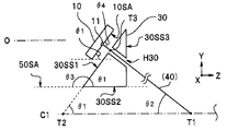
- FIG. 5A is a partially enlarged view of FIG. 3, and is a cross-sectional view showing a cut surface (YZ plane) including the optical axis O of the imaging optical system 2 and the central axis C1 of the hard tip.
- the optical axis O of the imaging optical system 2 and the central axis C1 of the hard tip 90A are parallel.
- the third major surface 50SA is parallel to the optical axis O and the central axis C1. Strictly speaking, the intersecting line of the third main surface 50SA with the surface including the optical axis O and the central axis C is parallel to the optical axis O and the central axis C1.
- the second side surface 30SS2 of the holding member 30 bonded to the third main surface 50SA is parallel to the optical axis O and the central axis C1.
- the light emitting surface 10SA of the light emitting element 10 and the first side surface 30SS1 of the holding member are parallel.
- the fourth angle ⁇ 4 (see FIG. 5B) with respect to the insertion hole H30 of the holding member 30, that is, the light emitting surface 10SA at the tip of the optical fiber 40 is 90 degrees. For this reason, the coupling efficiency between the light emitting element 10 and the optical fiber 40 is high.
- the angle of the light emitting surface 10SA of the light emitting element 10 with respect to the optical axis O is the same as the first angle ⁇ 1 formed by the first side surface 30SS1 and the second side surface 30SS2 of the holding member 30. Since the sum of the inner angles of the triangles having T1, T2, and T3 as vertices is 180 degrees, the second angle ⁇ 2 with respect to the central axis C1 of the tip portion of the optical fiber 40 is an additional angle of the first angle ⁇ 1. That is, the addition angle between the first angle ⁇ 1 and the second angle ⁇ 2 is 90 degrees.
- the second angle ⁇ 2 is not less than 35 degrees and not more than 55 degrees.
- an imaging element 70 is disposed on the second main surface 20SB of the third region C20 of the wiring board 20.
- the third region C20 is in contact with the side surface of the substantially rectangular parallelepiped semiconductor chip component 60 mounted on the wiring board 20, whereby the angle of the second bent portion W20B, that is, with respect to the optical axis O (center axis C1).
- a fifth angle ⁇ 5 is defined.
- an L-shaped member may be provided.
- the light emitting surface 10SA of the light emitting element 10 is inclined at the first angle ⁇ 1 with respect to the central axis, and the distal end portion of the optical fiber 40 is relative to the central axis. And inclined at the second angle ⁇ 2. Since the first angle ⁇ 1 is the remainder of the second angle ⁇ 2, the fourth angle ⁇ 4 with respect to the light emitting surface 10SA at the tip of the optical fiber 40 is 90 degrees. For this reason, the coupling efficiency between the light emitting element 10 and the optical fiber 40 is high.
- the holding member 30 defines the first angle ⁇ 1 and the second angle ⁇ 2 to be not less than 35 degrees and not more than 55 degrees. For this reason, since the endoscope 9 can arrange the optical fiber 40 at a short distance along the central axis C2 of the curved portion 90B, the endoscope 9 has a short length L90A of the rigid distal end portion 90A and is minimally invasive.
- the holding member 30A of the imaging module 1A of the endoscope 9A has a cylindrical shape.
- the insertion hole H30 having openings in the upper surface 30SA and the lower surface 30SB is perpendicular to the upper surface 30SA and the lower surface 30SB.
- the upper surface 30SA of the holding member 30A is bonded to the second main surface 20SB of the first region A20 of the wiring board 20.
- a part of the outer periphery of the lower surface 30SB of the holding member 30A is in contact with the third main surface 50SA of the substrate 50.
- substrate 50 is prescribed
- the third angle ⁇ 3 is a complementary angle of the first angle ⁇ 1 with respect to the optical axis O (center axis C1) of the light emitting surface 10SA of the light emitting element 10. Further, the first angle ⁇ 1 is a remainder angle of the second angle ⁇ 2 with respect to the optical axis O (center axis C1) of the tip portion of the optical fiber 40.
- the first angle ⁇ 1 and the second angle ⁇ 2 are defined as 45 ° ⁇ 10 ° by the length of the holding member 30A.
- the shape of the holding member is not limited to a triangular prism or a cylinder, and may be a polygonal column or the like.
- the endoscope 9A has the same effect as the endoscope 9.
- the wiring board 20B of the imaging module 1B of the endoscope 9B includes the first region A20 and the second region B20, and does not include the third region.
- the imaging module 1B includes a right-angle prism 2D that is a reflection unit that reflects a subject image condensed by the imaging optical system 2.
- the optical path of the optical signal becomes a direction (Y direction) orthogonal to the optical axis direction (Z direction).
- the reflecting part may be a mirror or the like.
- the imaging element 70 that receives the subject image reflected by the right-angle prism 2D is disposed on the first main surface 20SA of the second region B20 of the wiring board 20B.
- the imaging module 1B has the same effect as the imaging module 1. Furthermore, since the wiring board 20B does not include the second bent portion having a large bending angle, there is no possibility that the wiring is disconnected. Note that the holding member 30B is a substantially triangular prism with a chamfered corner, but may be a cylinder or the like as in the imaging module 1A.
- the imaging module 1C of the endoscope 9C of the second embodiment is similar to the imaging module 1 of the endoscope 9, etc., components having the same function are denoted by the same reference numerals and description thereof is omitted.
- the imaging module 1C does not include the substrate 50, which is an inflexible flat plate, unlike the imaging modules 1, 1A, and 1B.
- the substantially triangular prism holding member 30C is a three-dimensional wiring board made of molded circuit components (MID).
- An electrode pad 31 to which the electrode 12 of the light emitting element 10 is bonded is disposed on the first side face 30SS1 of the holding member 30C.
- the second side surface 30SS2 of the holding member is bonded to the first main surface 20SA of the wiring board 20C.
- the wiring of the holding member 30C is connected to the wiring of the wiring board 20C through a conductive paste or the like.
- the holding member 30C is a molded circuit component (MID) having an electrode pad 31 and wiring (not shown) using a non-conductive resin as a base material.
- the holding member 30C may be a three-dimensional wiring board made of ceramic.
- the holding member 30 ⁇ / b> C of the imaging module 1 ⁇ / b> C has a function of a wiring board on which the light emitting element 10 is mounted, while defining the direction of the tip of the optical fiber 40 (second angle ⁇ ⁇ b> 2).
- the endoscope 9C has the same effect as the endoscope 9.
- the imaging module 1D of the endoscope 9D according to the modified example of the second embodiment is similar to the imaging module 1B of the endoscope 9B and the imaging module 1C of the endoscope 9C, the components having the same functions are the same. Reference numerals are assigned and description is omitted.
- the wiring board 20 ⁇ / b> D of the imaging module 1 ⁇ / b> D has a flat plate shape without a bent portion. For this reason, the wiring board 20D may be inflexible. Then, on the first main surface 20SA of the wiring board 20D, an image sensor 70 that receives a subject image reflected by the right-angle prism 2D that is a reflecting portion, and a holding member 30D that is a three-dimensional wiring board made of MID are disposed. ing.
- the endoscope 9D has the effects of the endoscope 9B and the endoscope 9C. Furthermore, the endoscope 9D is easy to manufacture because the configuration of the imaging module 1D is simpler than the imaging module 1B and the like.
Abstract
内視鏡9は、挿入部90の硬性先端部90Aに撮像モジュール1が配設されており、前記撮像モジュール1が、光軸Oが硬性先端部90Aの中心軸C1と平行かつ偏心している撮像光学系2と、撮像素子70と、発光素子10と、第1の主面20SAと第2の主面20SBとを有する配線板20と、挿入孔H30のある保持部材30と、を具備し、発光素子10の発光面10SAが中心軸C1に対して、35度以上55度以下の第1の角度θ1で傾斜しており、光信号を伝送する光ファイバ40は、保持部材30の挿入孔H30に挿入されている先端部が中心軸C1に対して、35度以上55度以下の第2の角度θ2で傾斜しており、中心軸C2に向かって延設され、中心軸C2に沿って配置されている。
Description
本発明は、硬性先端部に配設された光モジュールの出射する光信号を伝送する光ファイバが、挿入部を挿通している内視鏡に関する。
内視鏡は、細長い挿入部の先端部にCCD等の撮像素子を有する。近年、高品質の画像を表示するため、高画素数の撮像素子が検討されている。高画素数の撮像素子を使用した場合には、撮像素子から信号処理装置(プロセッサ)へ伝送する画像信号量が増加する。このため、電気信号によるメタル配線を介した電気信号伝送では、配線のため挿入部が太くなるおそれがある。
挿入部を細径化し、低侵襲化するには、電気信号に替えて光信号による細い光ファイバを介した光信号伝送が好ましい。光信号伝送には、電気信号を光信号に変換するE/O型の光モジュール(電気-光変換器)と、光信号を電気信号に変換するO/E型の光モジュール(光-電気変換器)とが用いられる。
日本国特開2013-025092号公報には、光信号の入力または出力を行う光素子と、光素子が実装される基板と、光素子から入出力される光信号を伝送する光ファイバが挿入されている貫通孔を有する保持部と(フェルール)、を具備する光モジュールが開示されている。
ここで、光ファイバは、応力に対する強度が強くはない。このため、内視鏡の可撓性の挿入部、特に湾曲部が大きく変形することにより、光ファイバには、引張応力/圧縮応力が繰り返して印加されると、破損したり、折れたりするおそれがある。
日本国特開2015-97589号公報には、光ファイバが湾曲部の中心を挿通しているため、湾曲部が変形しても、光ファイバに応力が印加されない内視鏡が開示されている。
しかし、この内視鏡では、硬性先端部の中心軸に対して、フェルールに挿入されている光ファイバの先端部が平行に配置されている。そして、光素子の光軸が硬性先端部の中心軸と一致していないため、光ファイバを大きく曲げないと、湾曲部の中心軸に光ファイバを配置することはできない。ここで、「大きく曲げる」とは、曲率半径を小さくする(すなわち、曲率が大きくなる)という意味である。しかし、光ファイバを大きく曲げると破損するおそれがある。一方、光ファイバが破損しないように、曲げ角度を小さくすると、硬性先端部の長さが長くなり低侵襲化が容易ではなくなる。
本発明の実施形態は、高品質の画像を表示できる、信頼性の高い低侵襲の内視鏡を提供することを目的とする。
本発明の実施形態の内視鏡は、硬性先端部と湾曲部と軟性部とが連設されている挿入部の前記硬性先端部に、光信号を出射する撮像モジュールが配設されている内視鏡であって、前記撮像モジュールが、光軸が前記硬性先端部の中心軸と平行かつ偏心している撮像光学系と、前記撮像光学系が集光する被写体像を受光する撮像素子と、前記撮像素子が出力する撮像信号を前記光信号に変換し、発光面から前記光信号を出射する発光素子と、第1の主面と前記第1の主面と対向する第2の主面とを有し、前記撮像素子が配設されている配線板と、前記配線板に配設されている、挿入孔のある保持部材と、を具備し、前記発光素子の前記発光面が、前記中心軸に対して、35度以上55度以下の第1の角度で傾斜しており、前記発光素子と光結合するように配置されている前記光信号を伝送する光ファイバは、前記保持部材の前記挿入孔に挿入されている先端部が前記中心軸に対して、35度以上55度以下の第2の角度で傾斜しており、前記中心軸に向かって延設され、前記湾曲部においては前記中心軸に沿って配置されている。
本発明の実施形態によれば、高品質の画像を表示できる低侵襲の内視鏡を提供できる。
<第1実施形態>
図1に示すように、本実施形態の内視鏡9を含む内視鏡システム8は、内視鏡9と、プロセッサ80と、光源装置81と、モニタ82と、を具備する。例えば、内視鏡9は、断面が円形の挿入部90を被検体の体腔内に挿入されて、被検体の体内画像を撮影し撮像信号を出力する。
図1に示すように、本実施形態の内視鏡9を含む内視鏡システム8は、内視鏡9と、プロセッサ80と、光源装置81と、モニタ82と、を具備する。例えば、内視鏡9は、断面が円形の挿入部90を被検体の体腔内に挿入されて、被検体の体内画像を撮影し撮像信号を出力する。
なお、以下の説明において、各実施形態に基づく図面は、模式的なものであり、各部分の厚みと幅との関係、夫々の部分の厚みの比率などは現実のものとは異なることに留意すべきであり、図面の相互間においても互いの寸法の関係や比率が異なる部分が含まれている場合がある。また、一部の構成要素の図示、符号の付与を省略する場合がある。
内視鏡9の挿入部90の基端側には、内視鏡9を操作する各種ボタン類が設けられた操作部91が配設されている。操作部91には、被検体の体腔内に、生体鉗子、電気メスおよび検査プローブ等を挿入するチャンネル94(図2参照)の処置具挿入口がある。
挿入部90は、E/O型の光モジュール3(図3参照)を含む撮像モジュール1が配設されている硬性先端部90Aと、硬性先端部90Aの基端側に連設された湾曲自在な湾曲部90Bと、湾曲部90Bの基端側に連設された軟性部90Cとによって構成される。湾曲部90Bは、操作部91の操作によって湾曲する。
操作部91から延設されているユニバーサルコード92は、コネクタ93を介してプロセッサ80および光源装置81に接続される。ユニバーサルコード92には、O/E型の光モジュール3Xが出力する電気信号を伝送する信号ケーブル40Mが挿通している。
プロセッサ80は内視鏡システム8の全体を制御するとともに、撮像モジュール1が出力する撮像信号に信号処理を行い画像信号として出力する。モニタ82は、プロセッサ80が出力する画像信号を表示する。
光源装置81は、例えば、白色LEDを有する。光源装置81が出射する照明光は、ユニバーサルコード92および挿入部90を挿通するライトガイド(不図示)を介して先端部90Aの照明光学系96(図2参照)に導光され、被写体を照明する。
すなわち、内視鏡9では、撮像信号は硬性先端部90Aの光モジュール3で光信号に変換されて、挿入部90を挿通する細い光ファイバ40を介して操作部91まで伝送される。そして、操作部91に配設されているO/E型の光モジュール3Xにより光信号は再び電気信号に変換され、ユニバーサルコード92を挿通するメタル配線である信号ケーブル40Mを介して電気コネクタ93に伝送される。すなわち、撮像信号は、細径の挿入部90内においては光ファイバ40を介して伝送され、体内に挿入されず外径の制限の小さいユニバーサルコード92内においては光ファイバ40よりも太いメタル配線である信号ケーブル40Mを介して伝送される。
なお、光モジュール3Xがコネクタ93またはプロセッサ80に配置されている場合には、光ファイバ40はユニバーサルコード92を挿通している。
図2は、内視鏡9の硬性先端部90Aを先端側から見た正面図である。硬性先端部90Aは、樹脂からなる外皮5で外周面が覆われている、後部が筒状の円筒形の筐体4を含む。筐体4には、硬性先端部90Aの中心軸C1に平行な複数の貫通孔がある。
撮像光学系2の観察窓とチャンネル94の開口とは、硬性先端部90Aの中心軸C1(挿入部90の中心軸C)を間に、はさむように、先端面に配設されている。すなわち、筐体4の貫通孔に挿入されている撮像光学系2の光軸Oは、中心軸C1(C)と平行であり、かつ、偏心している。
先端面には、さらに、2つの照明光学系96の照明窓、および、送気送水用のノズル97が配設されている。
図3は、図2のIII-III線に示すように、撮像光学系2の光軸Oと硬性先端部90Aの中心軸Cとを含む面(YZ面)を示している。
撮像光学系2と光モジュール3とを含む撮像モジュール1は、長さL90Aの硬性先端部90Aの筐体4の貫通孔に収容されている。
撮像モジュール1から延設されている光ファイバ40は、例えば、光を伝送する50μm径のコアと、コアの外周を覆う125μm径のクラッドとからなる。先端部が光モジュール3に挿入されている光ファイバ40は、硬性先端部90Aの中心軸C1に向かって延設され、湾曲部90Bにおいては湾曲部90Bの中心軸C2に沿って配置されている。
すなわち、硬性先端部90Aの基端部および湾曲部90Bには、光ファイバ40を中心軸C1(中心軸C)に沿って配置するように構成されているガイド部材99が配設されている。ガイド部材99の詳細は、すでに説明した日本国特開2015-97589号公報に開示されている。図示しないが、軟性部90Cにも、ガイド部材99が配設されていることが好ましい。なお、軟性部90Cは、湾曲部90Bに比べると大きくは変形しないため、軟性部90Cにおけるガイド部材99の配置間隔は、湾曲部90Bにおける配置間隔も長くてもよい。
ガイド部材として、湾曲部90Bの内径と略同じ外径で、湾曲部90Bを挿通している1本のマルチルーメンチューブを用いてもよい。すなわち、マルチルーメンチューブの中央を挿通している管路に光ファイバ40を挿通することで、光ファイバ40を中心軸Cに沿って配置できる。
内視鏡9の挿入部90を挿通している光ファイバ40には、挿入部90が変形すると応力が印加される。光ファイバ40が大きな応力を受けるのは、特に、湾曲部90Bの湾曲操作による変形である。
内視鏡9では、光ファイバ40が、湾曲部90Bの中心軸C2に沿って配置されているため、湾曲部90Bが変形しても、光ファイバ40が大きな応力を受けることがない。このため、内視鏡9は、光ファイバ40が破損するおそれがなく、信頼性が高い。
さらに、図3に示すように、内視鏡9の撮像モジュール1では、光ファイバ40は、先端部が、中心軸Cおよび光軸Oを含む断面(YZ面)において、中心軸C1に対して第2の角度θ2である45度±10度、すなわち、35度以上55度以下に傾斜しており、延設方向が中心軸C1に向かって配置されている。
以上の説明のように、内視鏡9は、光ファイバを介して画像信号を伝送するため、高品質の画像が表示できる。また、光ファイバを大きく曲げることなく、湾曲部90Bの中心軸C2に沿って光ファイバを配置できるため、信頼性が高い。さらに、光ファイバ40を短い距離で湾曲部90Bの中心軸C2に沿って配置できるため、内視鏡9は硬性先端部90Aの長さL90Aが短く、低侵襲である。
次に図4、図5Aおよび図5Bを用いて、内視鏡9の撮像モジュール1の詳細について説明する。
撮像モジュール1は、撮像光学系2と光モジュール3とを含む。光モジュール3からは光ファイバ40が延設されている。
撮像光学系2は、複数のレンズ2Aおよび光学絞り2B等がレンズ鏡筒2Cに収容されている。光モジュール3は、発光素子10と配線板20と保持部材30と基板50と半導体チップ部品60と撮像素子70と、を有する。
配線板20は、第1の主面20SAと第2の主面20SBとを有する。可撓性の配線板20は、第1の領域A20と第2の領域B20と第3の領域C20とを含む。第1の領域A20と第2の領域B20とは第1の屈曲部W20Aを介して連設されている。第2の領域B20と第3の領域C20とは第2の屈曲部W20Bを介して連設されている。
なお、第1の領域A20と第1の屈曲部W20Aと第2の領域B20と第2の屈曲部W20Bと第3の領域C20とは1枚の可撓性の配線板20からなり、その境界は明確ではない。
基板50は、セラミック、ガラス、またはシリコン等からなる非可撓性の平板である。なお、基板50は第3の主面50SAが平面であればよく、第3の主面50SAと対向する主面が平行な平行平板に限られるものではない。また、配線および電極が配設された基板50に信号ケーブル等が接続されていてもよい。
配線板20、基板50および保持部材30は、接着層(不図示)を介して接着されている。
基板50の第3の主面50SAは、筐体4の中心軸C1と平行な貫通孔の壁面に平行に配置されている。このため、第3の主面50SAに接着されている第2の領域B20は、中心軸C1に平行に配置されている。言い替えれば、第2の領域B20の中心軸C1に対する角度は、0度である。
これに対して、第1の領域A20は、第2の領域B20に対して第3の角度θ3で傾斜している。すなわち、第1の屈曲部W20Aの屈曲角度である第3の角度θ3は、125度以上145度以下(135度±10度)である。後述するように、第3の角度θ3は、保持部材30の第1の角度θ1(図4参照)の補角である(θ1+θ3=180度)。
なお、第3の領域C20は、第2の領域B20に対して垂直である。すなわち、第2屈曲部W20Bの屈曲角度である第5の角度θ5は、90度である。
配線板20の基体は、可撓性のポリイミド樹脂等である。なお、配線板は、第1の領域A20~第3の領域C20が非可撓性のリジッド部で、第1の屈曲部W20Aおよび第2の屈曲部W20Bが可撓性のリジットフレキシブル基板でもよい。
発光素子10は、光信号の光を出力する発光部11を有する面発光レーザーチップである。例えば、平面視寸法が250μm×300μmと超小型の発光素子10は、直径が20μmの発光部11と、発光部11に駆動信号を供給する電極12とを発光面10SAに有する。
撮像素子70は、CMOS(Complementary Metal Oxide Semiconductor)イメージセンサ、又は、CCD(Charge Coupled Device)等である。撮像素子70の受光面70SAには受光部71が形成されたおり、受光面70SAと対向する裏面70SBには受光部71と接続された電極72が配設されている。
半導体チップ部品60は、撮像素子70が出力する画像信号を、発光素子10を駆動する駆動信号に変換する駆動ICである。なお、図示しないが、半導体チップ部品60だけでなく、チップコンデンサ等の複数のチップ部品が配線板20に実装されていてもよい。逆に、半導体チップ部品60が、配線板20に実装されていなくともよい。また、半導体チップ部品60および撮像素子70等には、配線板20に接続されている図示しないケーブルを介して電力等が供給される。
配線板20の第1の領域A20には、光路となる孔H20がある。そして、第1の領域A20の第1の主面20SAには発光素子10が、発光部11が配線板20の孔H20と対向する位置に配置された状態で、フリップチップ実装されている。すなわち、配線板20は発光素子10の複数の電極12と、それぞれが接合された電極パッド21を有する。なお、配線板20が光信号の光を透過する基体を有する場合には、光路となる孔H20は不要である。
発光面10SAは、配線板20の第1の領域A20と平行に配設されている。このため、発光面10SAは中心軸C1に対して、35度以上55度以下の第1の角度θ1で傾斜している。
一方、第1の領域A20の第2の主面20SBには、光ファイバ40の先端部が挿入されている挿入孔H30のある保持部材(フェルール)30が接着されている。
挿入孔H30の内壁形状は、円柱状のほか、その壁面で光ファイバ40を保持できれば、角柱状であってもよい。保持部材30の材質は、ガラスもしくはSUS等の金属部材、セラミック、または、シリコン等である。
撮像モジュール1の保持部材30は、第1の側面30SS1と第2の側面30SS2と第3の側面30SS3とを有する略三角柱である。挿入孔H30は、第1の側面30SS1と第3の側面30SS3とに開口を有する。
挿入孔H30は第1の側面30SS1に対して垂直であり、第1の側面30SS1と第2の側面30SS2とがなす角度が第1の角度θ1である。
撮像モジュール1では、略三角柱である保持部材30の第1の側面30SS1が、配線板20の第1の領域A20の第2の主面と面接触し、第2の側面30SS2が基板50の第3の主面50SAと面接触しているため、第1の屈曲部W20Aを、容易に、かつ、確実に、第3の角度θ3とすることができる。
また、挿入孔H30に、光ファイバ40を挿入することで、発光素子10の発光部11と光ファイバ40との位置決めが自動的に行われる。
図5Aは、図3の部分拡大図であり、撮像光学系2の光軸Oと硬性先端部の中心軸C1とを含む切断面(YZ面)を示す断面図である。撮像光学系2の光軸Oと硬性先端部90Aの中心軸C1とは平行である。第3の主面50SAは、光軸Oおよび中心軸C1と平行である。厳密には、第3の主面50SAの、光軸Oと中心軸Cとを含む面との交差線は、光軸Oおよび中心軸C1と平行である。また、第3の主面50SAに接着されている保持部材30の第2の側面30SS2は、光軸Oおよび中心軸C1と平行である。
一方、発光素子10の発光面10SAと保持部材の第1の側面30SS1は平行である。また、保持部材30の挿入孔H30、すなわち、光ファイバ40の先端部の発光面10SAに対する第4の角度θ4(図5B参照)は、90度である。このため、発光素子10と光ファイバ40との結合効率が高い。
発光素子10の発光面10SAの光軸O(中心軸C1)に対する角度は、保持部材30の第1の側面30SS1と第2の側面30SS2とがなす第1の角度θ1と同じである。T1、T2およびT3を頂点とする三角形の内角の合計は180度であるため、光ファイバ40の先端部の中心軸C1に対する第2の角度θ2は、第1の角度θ1の余角となる。すなわち、第1の角度θ1と第2の角度θ2との加算角度は90度である。
第1の角度θ1が、35度以上55度以下であるため、第2の角度θ2は、35度以上55度以下である。
なお、配線板20の第3の領域C20の第2の主面20SBには、撮像素子70が配設されている。第3の領域C20は、配線板20に実装されている略直方体の半導体チップ部品60の側面と当接することで、第2の屈曲部W20Bの角度、すなわち、光軸O(中心軸C1)に対する第5の角度θ5が規定されている。
なお、第2の屈曲部W20Bの第5の角度θ5を規定するために、例えば、L字形部材を具備していてもよい。
以上の説明のように、内視鏡9は、発光素子10の発光面10SAが中心軸に対して第1の角度θ1で傾斜しており、かつ、光ファイバ40の先端部が中心軸に対して第2の角度θ2で傾斜している。そして、第1の角度θ1は第2の角度θ2の余角であるため、光ファイバ40の先端部の発光面10SAに対する第4の角度θ4は、90度である。このため、発光素子10と光ファイバ40の結合効率が高い。
さらに、保持部材30により、第1の角度θ1および第2の角度θ2が35度以上55度以下に、規定されている。このため、内視鏡9は、光ファイバ40を短い距離で湾曲部90Bの中心軸C2に沿って配置できるため、内視鏡9は硬性先端部90Aの長さL90Aが短く低侵襲である。
<第1実施形態の変形例>
第1実施形態の変形例の内視鏡9A、9Bの撮像モジュール1A、1Bは、内視鏡9の撮像モジュール1と類似しているため、同じ機能の構成要素には同じ符号を付し説明は省略する。
第1実施形態の変形例の内視鏡9A、9Bの撮像モジュール1A、1Bは、内視鏡9の撮像モジュール1と類似しているため、同じ機能の構成要素には同じ符号を付し説明は省略する。
<第1実施形態の変形例1>
図6に示すように、内視鏡9Aの撮像モジュール1Aの保持部材30Aは、円筒形である。上面30SAおよび下面30SBに開口を有する挿入孔H30は、上面30SAおよび下面30SBに対して垂直である。
図6に示すように、内視鏡9Aの撮像モジュール1Aの保持部材30Aは、円筒形である。上面30SAおよび下面30SBに開口を有する挿入孔H30は、上面30SAおよび下面30SBに対して垂直である。
保持部材30Aの上面30SAは、配線板20の第1の領域A20の第2の主面20SBに接着されている。一方、保持部材30Aの下面30SBの外周の一部は、基板50の第3の主面50SAと当接している。
保持部材30Aが、基板50の第3の主面50SAと当接することで、配線板20の第1の領域A20の第2の領域B20に対する第3の角度θ3が、規定されている。第3の角度θ3は、発光素子10の発光面10SAの光軸O(中心軸C1)に対する第1の角度θ1の補角である。さらに、第1の角度θ1は、光ファイバ40の先端部の光軸O(中心軸C1)に対する第2の角度θ2の余角である。
このため、撮像モジュール1Aでは、保持部材30Aの長さにより第1の角度θ1および第2の角度θ2が、45度±10度に規定されている。
第1の角度θ1および第2の角度θ2が、保持部材により規定されていれば、保持部材の形状は、三角柱または円筒に限られるものではなく多角柱等であってもよい。
内視鏡9Aは、内視鏡9と同じ効果を有する。
<第1実施形態の変形例2>
図7に示すように、内視鏡9Bの撮像モジュール1Bの配線板20Bは、第1の領域A20と第2の領域B20とを含み、第3の領域を含んでいない。
図7に示すように、内視鏡9Bの撮像モジュール1Bの配線板20Bは、第1の領域A20と第2の領域B20とを含み、第3の領域を含んでいない。
撮像モジュール1Bは、撮像光学系2が集光する被写体像を反射する反射部である直角プリズム2Dを具備する。直角プリズム2Dにより、光信号の光路は光軸方向(Z方向)と直交する方向(Y方向)となる。なお、反射部は、鏡等であってもよい。
すなわち、撮像モジュール1Bでは、配線板20Bの第2の領域B20の第1の主面20SAに、直角プリズム2Dにより反射された被写体像を受光する撮像素子70が配設されている。
撮像モジュール1Bは、撮像モジュール1と同じ効果を有する。さらに、配線板20Bは屈曲角度の大きい第2の屈曲部を含んでいないため、配線が断線するおそれがない。なお、保持部材30Bは、角が大きく面取りされた略三角柱であるが、撮像モジュール1Aと同じように円筒等であってもよい。
<第2実施形態>
第2実施形態の内視鏡9Cの撮像モジュール1Cは、内視鏡9の撮像モジュール1等と類似しているため、同じ機能の構成要素には同じ符号を付し説明は省略する。
第2実施形態の内視鏡9Cの撮像モジュール1Cは、内視鏡9の撮像モジュール1等と類似しているため、同じ機能の構成要素には同じ符号を付し説明は省略する。
図8に示すように、撮像モジュール1Cは、撮像モジュール1、1A、1Bと異なり非可撓性の平板である基板50を具備しない。
そして、略三角柱の保持部材30Cは、成形回路部品(MID)からなる立体配線板である。保持部材30Cの第1の側面30SS1には、発光素子10の電極12が接合されている電極パッド31が配設されている。一方、保持部材の第2の側面30SS2は、配線板20Cの第1の主面20SAに接着されている。図示しないが、保持部材30Cの配線は、導電ペースト等を介して、配線板20Cの配線と接続されている。
保持部材30Cは、非導電性樹脂を母材とし電極パッド31および配線(不図示)を有する成形回路部品(MID)である。保持部材30Cは、セラミックからなる立体配線板でもよい。
撮像モジュール1Cの保持部材30Cは、光ファイバ40の先端部の方向(第2の角度θ2)を規定すると同時に、発光素子10が実装された配線板の機能を有する。
内視鏡9Cは内視鏡9と同じ効果を有する。
<第2実施形態の変形例>
第2実施形態の変形例の内視鏡9Dの撮像モジュール1Dは、内視鏡9Bの撮像モジュール1Bおよび内視鏡9Cの撮像モジュール1Cと類似しているため、同じ機能の構成要素には同じ符号を付し説明は省略する。
第2実施形態の変形例の内視鏡9Dの撮像モジュール1Dは、内視鏡9Bの撮像モジュール1Bおよび内視鏡9Cの撮像モジュール1Cと類似しているため、同じ機能の構成要素には同じ符号を付し説明は省略する。
図9に示すように、撮像モジュール1Dの配線板20Dは、屈曲部のない平板状である。このため、配線板20Dは、非可撓性でもよい。そして、配線板20Dの第1の主面20SAに、反射部である直角プリズム2Dにより反射された被写体像を受光する撮像素子70と、MIDからなる立体配線板である保持部材30Dが配設されている。
内視鏡9Dは、内視鏡9Bと内視鏡9Cの効果を有する。さらに、内視鏡9Dは、撮像モジュール1Dの構成が、撮像モジュール1B等よりも、単純であるため製造が容易である。
本発明は、上述した実施形態および変形例等に限定されるものではなく、発明の趣旨を逸脱しない範囲内において種々の変更、組み合わせおよび応用が可能である。
1、1A~1D・・・撮像モジュール
2・・・撮像光学系
3・・・光モジュール
8・・・内視鏡システム
9、9A~9D・・・内視鏡
10・・・発光素子
20・・・配線板
30、30A~30D・・・保持部材
40・・・光ファイバ
40M・・・信号ケーブル
50・・・基板
60・・・半導体チップ部品
70・・・撮像素子
80・・・プロセッサ
81・・・光源装置
82・・・モニタ
90・・・挿入部
90A・・・硬性先端部
99・・・ガイド部材
2・・・撮像光学系
3・・・光モジュール
8・・・内視鏡システム
9、9A~9D・・・内視鏡
10・・・発光素子
20・・・配線板
30、30A~30D・・・保持部材
40・・・光ファイバ
40M・・・信号ケーブル
50・・・基板
60・・・半導体チップ部品
70・・・撮像素子
80・・・プロセッサ
81・・・光源装置
82・・・モニタ
90・・・挿入部
90A・・・硬性先端部
99・・・ガイド部材
Claims (9)
- 硬性先端部と湾曲部と軟性部とが連設されている挿入部の前記硬性先端部に、光信号を出射する撮像モジュールが配設されている内視鏡であって、
前記撮像モジュールが、
光軸が前記硬性先端部の中心軸と平行かつ偏心している撮像光学系と、
前記撮像光学系が集光する被写体像を受光する撮像素子と、
前記撮像素子が出力する撮像信号を前記光信号に変換し、発光面から前記光信号を出射する発光素子と、
第1の主面と前記第1の主面と対向する第2の主面とを有し、前記撮像素子が配設されている配線板と、
前記配線板に配設されている、挿入孔のある保持部材と、を具備し、
前記発光素子の前記発光面が、前記中心軸に対して、35度以上55度以下の第1の角度で傾斜しており、
前記発光素子と光結合するように配置されている前記光信号を伝送する光ファイバは、前記保持部材の前記挿入孔に挿入されている先端部が前記中心軸に対して、35度以上55度以下の第2の角度で傾斜しており、前記中心軸に向かって延設され、前記湾曲部においては前記中心軸に沿って配置されていることを特徴とする内視鏡。 - 前記第1の角度および前記第2の角度が、前記保持部材により規定されていることを特徴とする請求項1に記載の内視鏡。
- 前記保持部材が、第1の側面と第2の側面と第3の側面とを有し、前記挿入孔が前記第1の側面と前記第3の側面とに開口を有し、
前記第1の側面と前記第2の側面とがなす角度が、前記第1の角度であることを特徴とする請求項2に記載の内視鏡。 - 前記撮像モジュールが、第3の主面を有する基板を、さらに具備し、
前記配線板が、第1の屈曲部を介して連設されている第1の領域と第2の領域とを含み、
前記第1の領域の前記第1の主面に前記発光素子が配設され、
前記第1の領域の前記第2の主面に前記保持部材の前記第1の側面が接着され、
前記基板の前記第3の主面に、前記第2の領域の前記第2の主面および前記保持部材の前記第2の側面が接着されていることを特徴とする請求項3に記載の内視鏡。 - 前記配線板が、第2の屈曲部を介して前記第2の領域と連設されている第3の領域を含み、
前記配線板の前記第3の領域の前記第2の主面に、前記撮像素子が配設されており、前記第3の領域は前記第2の領域に対して垂直であることを特徴とする請求項4に記載の内視鏡。 - 前記撮像モジュールが、前記撮像光学系が集光する被写体像を反射する反射部をさらに具備し、
前記配線板の前記第2の領域の前記第1の主面に、前記反射部により反射された前記被写体像を受光する前記撮像素子が配設されていることを特徴とする請求項4に記載の内視鏡。 - 前記保持部材が、立体配線板であり、
前記第1の側面に前記発光素子が配設され、前記第2の側面が前記第1の主面に接着されていることを特徴とする請求項3に記載の内視鏡。 - 前記配線板が、第2の屈曲部を介して連設されている第2の領域と第3の領域を含み、
前記保持部材が前記第2の領域に配設され、
前記第3の領域の前記第2の主面に、前記撮像素子が配設されており、前記第3の領域は前記第2の領域に対して垂直であることを特徴とする請求項7に記載の内視鏡。 - 前記撮像モジュールが、前記撮像光学系が集光する被写体像を反射する反射部をさらに具備し、
前記第1の主面に、前記反射部により反射された前記被写体像を受光する前記撮像素子が配設されていることを特徴とする請求項7に記載の内視鏡。
Priority Applications (5)
| Application Number | Priority Date | Filing Date | Title |
|---|---|---|---|
| PCT/JP2017/002354 WO2018138778A1 (ja) | 2017-01-24 | 2017-01-24 | 内視鏡 |
| PCT/JP2017/033883 WO2018138962A1 (ja) | 2017-01-24 | 2017-09-20 | 内視鏡 |
| PCT/JP2018/001817 WO2018139406A1 (ja) | 2017-01-24 | 2018-01-22 | 内視鏡および内視鏡の製造方法 |
| US16/515,240 US10819960B2 (en) | 2017-01-24 | 2019-07-18 | Endoscope |
| US16/517,138 US10972707B2 (en) | 2017-01-24 | 2019-07-19 | Endoscope and method of manufacturing endoscope |
Applications Claiming Priority (1)
| Application Number | Priority Date | Filing Date | Title |
|---|---|---|---|
| PCT/JP2017/002354 WO2018138778A1 (ja) | 2017-01-24 | 2017-01-24 | 内視鏡 |
Publications (1)
| Publication Number | Publication Date |
|---|---|
| WO2018138778A1 true WO2018138778A1 (ja) | 2018-08-02 |
Family
ID=62978521
Family Applications (2)
| Application Number | Title | Priority Date | Filing Date |
|---|---|---|---|
| PCT/JP2017/002354 WO2018138778A1 (ja) | 2017-01-24 | 2017-01-24 | 内視鏡 |
| PCT/JP2017/033883 WO2018138962A1 (ja) | 2017-01-24 | 2017-09-20 | 内視鏡 |
Family Applications After (1)
| Application Number | Title | Priority Date | Filing Date |
|---|---|---|---|
| PCT/JP2017/033883 WO2018138962A1 (ja) | 2017-01-24 | 2017-09-20 | 内視鏡 |
Country Status (2)
| Country | Link |
|---|---|
| US (2) | US10819960B2 (ja) |
| WO (2) | WO2018138778A1 (ja) |
Families Citing this family (4)
| Publication number | Priority date | Publication date | Assignee | Title |
|---|---|---|---|---|
| EP3544482A4 (en) | 2016-11-28 | 2020-07-22 | Adaptivendo LLC | SEPARABLE DISPOSABLE SHAFT ENDOSCOPE |
| WO2020148820A1 (ja) * | 2019-01-16 | 2020-07-23 | オリンパス株式会社 | 内視鏡先端構造、および内視鏡 |
| USD1018844S1 (en) | 2020-01-09 | 2024-03-19 | Adaptivendo Llc | Endoscope handle |
| CN111796375B (zh) * | 2020-08-06 | 2023-12-05 | 上海瑞柯恩激光技术有限公司 | 传输光纤、激光光纤结构及传输光纤的制备方法 |
Citations (5)
| Publication number | Priority date | Publication date | Assignee | Title |
|---|---|---|---|---|
| JP2014137584A (ja) * | 2013-01-18 | 2014-07-28 | Olympus Corp | 光伝送モジュールおよび撮像装置 |
| JP2015068835A (ja) * | 2013-09-26 | 2015-04-13 | オリンパス株式会社 | 光伝送モジュール、及び内視鏡 |
| JP2015097588A (ja) * | 2013-11-18 | 2015-05-28 | オリンパス株式会社 | 光伝送モジュール及び内視鏡 |
| WO2015079780A1 (ja) * | 2013-11-28 | 2015-06-04 | オリンパス株式会社 | 内視鏡 |
| WO2016189691A1 (ja) * | 2015-05-27 | 2016-12-01 | オリンパス株式会社 | 内視鏡および光伝送モジュール |
Family Cites Families (14)
| Publication number | Priority date | Publication date | Assignee | Title |
|---|---|---|---|---|
| JPH1144831A (ja) | 1997-07-28 | 1999-02-16 | Nippon Telegr & Teleph Corp <Ntt> | 半導体レーザモジュール |
| JP2001281503A (ja) | 2000-03-30 | 2001-10-10 | Seiko Epson Corp | 光モジュールおよびその製造方法 |
| JP2009244702A (ja) | 2008-03-31 | 2009-10-22 | Asahi Kasei E-Materials Corp | 光通信モジュール、光通信モジュールの製造方法、プラスチック光ファイバモジュール、プラスチック光ファイバモジュールを用いた光信号伝送方法、電子機器及び電子機器の製造方法 |
| JP2010186090A (ja) * | 2009-02-13 | 2010-08-26 | Hitachi Ltd | 光送受信モジュール |
| JP2010219166A (ja) | 2009-03-13 | 2010-09-30 | Nippon Electric Glass Co Ltd | 半導体発光素子デバイス |
| US8919053B2 (en) * | 2009-07-02 | 2014-12-30 | Zep Solar, Llc | Leveling foot apparatus, system, and method for photovoltaic arrays |
| EP2618556B1 (en) * | 2010-12-14 | 2015-05-27 | Olympus Medical Systems Corp. | Imaging apparatus |
| JP5809866B2 (ja) | 2011-07-21 | 2015-11-11 | オリンパス株式会社 | 光素子モジュール、光伝送モジュール、および光伝送モジュールの製造方法 |
| US20140236194A1 (en) * | 2013-02-15 | 2014-08-21 | Lmk Research, Llc | Spinal dural repair instruments and methods for using same |
| JP6411088B2 (ja) * | 2013-09-26 | 2018-10-24 | オリンパス株式会社 | 光伝送モジュールおよび内視鏡 |
| JP6203010B2 (ja) * | 2013-11-18 | 2017-09-27 | オリンパス株式会社 | 内視鏡 |
| JP6421557B2 (ja) | 2014-11-20 | 2018-11-14 | 日立金属株式会社 | 光モジュール及び光ケーブル |
| JP6485840B2 (ja) | 2015-01-23 | 2019-03-20 | オリンパス株式会社 | 光伝送モジュールおよび内視鏡 |
| WO2018139406A1 (ja) * | 2017-01-24 | 2018-08-02 | オリンパス株式会社 | 内視鏡および内視鏡の製造方法 |
-
2017
- 2017-01-24 WO PCT/JP2017/002354 patent/WO2018138778A1/ja active Application Filing
- 2017-09-20 WO PCT/JP2017/033883 patent/WO2018138962A1/ja active Application Filing
-
2019
- 2019-07-18 US US16/515,240 patent/US10819960B2/en active Active
- 2019-07-19 US US16/517,138 patent/US10972707B2/en active Active
Patent Citations (5)
| Publication number | Priority date | Publication date | Assignee | Title |
|---|---|---|---|---|
| JP2014137584A (ja) * | 2013-01-18 | 2014-07-28 | Olympus Corp | 光伝送モジュールおよび撮像装置 |
| JP2015068835A (ja) * | 2013-09-26 | 2015-04-13 | オリンパス株式会社 | 光伝送モジュール、及び内視鏡 |
| JP2015097588A (ja) * | 2013-11-18 | 2015-05-28 | オリンパス株式会社 | 光伝送モジュール及び内視鏡 |
| WO2015079780A1 (ja) * | 2013-11-28 | 2015-06-04 | オリンパス株式会社 | 内視鏡 |
| WO2016189691A1 (ja) * | 2015-05-27 | 2016-12-01 | オリンパス株式会社 | 内視鏡および光伝送モジュール |
Also Published As
| Publication number | Publication date |
|---|---|
| US20200007829A1 (en) | 2020-01-02 |
| US10819960B2 (en) | 2020-10-27 |
| WO2018138962A1 (ja) | 2018-08-02 |
| US20200012085A1 (en) | 2020-01-09 |
| US10972707B2 (en) | 2021-04-06 |
Similar Documents
| Publication | Publication Date | Title |
|---|---|---|
| US9462933B2 (en) | Image pickup unit for endoscope | |
| US10819960B2 (en) | Endoscope | |
| JP5839811B2 (ja) | 撮像ユニット及び内視鏡 | |
| US9207412B2 (en) | Optical transmission module and endoscope | |
| US11172812B2 (en) | Endoscope | |
| US11435570B2 (en) | Image pickup apparatus for endoscope, endoscope, and manufacturing method of image pickup apparatus for endoscope | |
| US10088669B2 (en) | Endoscope | |
| US11330972B2 (en) | Oblique-viewing endoscope | |
| WO2017109930A1 (ja) | 撮像モジュールおよび内視鏡 | |
| US9629524B2 (en) | Image pickup unit for endoscope having first and second leads with differing distances to image pickup device | |
| WO2019176601A1 (ja) | 撮像ユニットおよび斜視型内視鏡 | |
| US20200237194A1 (en) | Endoscope and endoscope system | |
| WO2018139406A1 (ja) | 内視鏡および内視鏡の製造方法 | |
| WO2021176596A1 (ja) | 内視鏡用撮像装置、および、内視鏡 | |
| US10838194B2 (en) | Optical transmission module and endoscope | |
| US20200049908A1 (en) | Optical module and endoscope | |
| US20240081620A1 (en) | Endoscope | |
| US20210382250A1 (en) | Manufacturing method for image pickup apparatus for endoscope, image pickup apparatus for endoscope, and endoscope | |
| WO2020179067A1 (ja) | 内視鏡用光トランスデューサ、内視鏡用撮像装置、および内視鏡 | |
| CN115363511A (zh) | 内窥镜摄像装置及内窥镜 | |
| CN116889370A (zh) | 内窥镜摄像装置及内窥镜 | |
| JP2022179301A (ja) | 内視鏡撮像装置及び内視鏡 | |
| CN115067861A (zh) | 内窥镜摄像装置及内窥镜 | |
| JP2012179306A (ja) | 撮像ユニット及び内視鏡 |
Legal Events
| Date | Code | Title | Description |
|---|---|---|---|
| 121 | Ep: the epo has been informed by wipo that ep was designated in this application |
Ref document number: 17894618 Country of ref document: EP Kind code of ref document: A1 |
|
| NENP | Non-entry into the national phase |
Ref country code: DE |
|
| 122 | Ep: pct application non-entry in european phase |
Ref document number: 17894618 Country of ref document: EP Kind code of ref document: A1 |
|
| NENP | Non-entry into the national phase |
Ref country code: JP |