WO2018135050A1 - 監視装置 - Google Patents
監視装置 Download PDFInfo
- Publication number
- WO2018135050A1 WO2018135050A1 PCT/JP2017/036753 JP2017036753W WO2018135050A1 WO 2018135050 A1 WO2018135050 A1 WO 2018135050A1 JP 2017036753 W JP2017036753 W JP 2017036753W WO 2018135050 A1 WO2018135050 A1 WO 2018135050A1
- Authority
- WO
- WIPO (PCT)
- Prior art keywords
- subject
- signal
- monitoring device
- determination unit
- monitoring
- Prior art date
- Legal status (The legal status is an assumption and is not a legal conclusion. Google has not performed a legal analysis and makes no representation as to the accuracy of the status listed.)
- Ceased
Links
Images



Classifications
-
- A—HUMAN NECESSITIES
- A61—MEDICAL OR VETERINARY SCIENCE; HYGIENE
- A61B—DIAGNOSIS; SURGERY; IDENTIFICATION
- A61B5/00—Measuring for diagnostic purposes; Identification of persons
-
- A—HUMAN NECESSITIES
- A61—MEDICAL OR VETERINARY SCIENCE; HYGIENE
- A61B—DIAGNOSIS; SURGERY; IDENTIFICATION
- A61B5/00—Measuring for diagnostic purposes; Identification of persons
- A61B5/103—Measuring devices for testing the shape, pattern, colour, size or movement of the body or parts thereof, for diagnostic purposes
- A61B5/11—Measuring movement of the entire body or parts thereof, e.g. head or hand tremor or mobility of a limb
-
- G—PHYSICS
- G08—SIGNALLING
- G08B—SIGNALLING SYSTEMS, e.g. PERSONAL CALLING SYSTEMS; ORDER TELEGRAPHS; ALARM SYSTEMS
- G08B21/00—Alarms responsive to a single specified undesired or abnormal condition and not otherwise provided for
- G08B21/02—Alarms for ensuring the safety of persons
-
- G—PHYSICS
- G08—SIGNALLING
- G08B—SIGNALLING SYSTEMS, e.g. PERSONAL CALLING SYSTEMS; ORDER TELEGRAPHS; ALARM SYSTEMS
- G08B25/00—Alarm systems in which the location of the alarm condition is signalled to a central station, e.g. fire or police telegraphic systems
- G08B25/01—Alarm systems in which the location of the alarm condition is signalled to a central station, e.g. fire or police telegraphic systems characterised by the transmission medium
- G08B25/04—Alarm systems in which the location of the alarm condition is signalled to a central station, e.g. fire or police telegraphic systems characterised by the transmission medium using a single signalling line, e.g. in a closed loop
Definitions
- the present disclosure relates to a monitoring device, and more particularly, to a monitoring device for monitoring a subject on a bedding.
- the present application claims priority based on Japanese Patent Application No. 2017-008200, which is a Japanese patent application filed on January 20, 2017. All the descriptions described in the Japanese patent application are incorporated herein by reference.
- Patent Document 1 discloses a safety monitoring device that collects biological information of a subject and monitors the safety of the subject.
- the safety monitoring device irradiates the subject with microwaves, detects the subject's body movement and respiration from the Doppler-shifted reflected wave, and detects the subject's body movement and respiration rate within a predetermined time. The safety of the person.
- the number of body movements and the number of breaths are calculated using a microwave Doppler shift signal output from a microwave Doppler sensor, and the safety of a subject is monitored using a safety pattern that is a combination of these. To do.
- the present disclosure is intended to provide a monitoring device capable of ensuring the safety of the subject by appropriately detecting the rising motion of the subject.
- a monitoring device for monitoring a subject on a bedding.
- the monitoring device determines whether the subject has been awakened based on the reception unit that receives the reflected wave of the microwave irradiated to the subject and the amplitude of the reflected wave signal and the first threshold at a predetermined time interval.
- a rising determination unit that determines whether or not, and an output control unit that outputs warning information when the rising determination unit determines that the subject has risen.
- FIG. 3 is a block diagram for illustrating a detailed configuration of a control circuit according to the first embodiment.
- FIG. It is a figure which shows the waveform of the reflected signal detected with the microwave Doppler sensor according to Embodiment 1. It is a figure which shows the Example at the time of installing a monitoring apparatus as shown in FIG.
- FIG. It is a figure for demonstrating the installation system of the monitoring apparatus according to Embodiment 2.
- FIG. It is a figure which shows the time change of the body motion amplitude at the time of installing a monitoring apparatus as shown in FIG.
- FIG. It is a figure for demonstrating the installation system of the monitoring apparatus according to Embodiment 3.
- FIG. It is a figure which shows the time change of the body motion amplitude at the time of installing a monitoring apparatus as shown in FIG.
- FIG. It is a figure which shows an example of the process sequence of a monitoring apparatus.
- FIG. 4 It is a figure for demonstrating the structure of the monitoring system according to Embodiment 4.
- FIG. 1 is a diagram showing an overall configuration of a monitoring system 1000 according to the first embodiment.
- monitoring system 1000 includes a monitoring device 100 for monitoring a subject and a terminal device 200.
- the terminal device 200 is a terminal on the side of watching a subject who is a person to be watched, for example, a smartphone.
- the terminal device 200 may be another device such as a foldable mobile phone, a tablet terminal device, or a personal computer (PC).
- PC personal computer
- the network 55 for connecting the monitoring device 100 and the terminal device 200 to each other includes various networks such as the Internet and a mobile terminal communication network.
- the network 55 is not limited to this, and a wired communication method may be adopted, or other wireless communication methods such as a wireless LAN (local area network) may be adopted.
- the monitoring apparatus 100 includes a control circuit 152, a memory 154, a speaker 156, a communication interface 158, and a microwave Doppler sensor 160 as main components.
- the monitoring device 100 may include a display for displaying various information and an input device such as a button for receiving various inputs from the user.
- the control circuit 152 typically includes a microprocessor including a CPU and the like, an analog signal processing circuit that processes an analog signal from the microwave Doppler sensor 160, and an AD converter. A detailed configuration of the control circuit 152 will be described later.
- the microprocessor functions as a control unit that controls the operation of each unit of the monitoring apparatus 100 by reading and executing the program stored in the memory 154. For example, the microprocessor implements the processing of the control circuit 152 described later by executing the program.
- the memory 154 is realized by a RAM (Random Access Memory), a ROM (Read-Only Memory), or the like.
- the memory 154 stores a program executed by the microprocessor or data used by the microprocessor.
- the speaker 156 converts an audio signal given from the microprocessor into audio and outputs it to the outside of the monitoring device 100.
- the communication interface 158 encodes communication data from the microprocessor, converts it into a communication signal, and transmits the communication signal to the terminal device 200.
- the reception signal from the terminal device 200 is decoded, converted into communication data, and output to the microprocessor.
- the communication method may be a wireless communication method using a wireless LAN or the like, or a wired communication method using USB (Universal Serial Bus) or the like.
- the microwave Doppler sensor 160 emits a microwave to the subject and outputs a signal reflecting the movement of the subject's body to the control circuit 152 from the reflected microwave. Further, the microwave Doppler sensor 160 generates an I channel signal and a Q channel signal that are orthogonal to each other from the input reflected signal.
- the microwave Doppler sensor 160 includes an oscillation circuit 21, amplifiers 22A and 22B, a transmission antenna 25, a reception antenna 30, mixers 32I and 32Q, and low-pass filters (LPF) 33I and 33Q, and 90. Degree phase shifter 38.
- the transmission antenna 25 and the reception antenna 30 are configured by planar antennas.
- the transmission antenna 25 and the reception antenna 30 may be configured with a waveguide antenna or a dielectric antenna.
- the microwave sine wave signal output from the oscillation circuit 21 is amplified by the amplifier 22A and radiated from the transmission antenna 25.
- the microwave Mt radiated to the space is reflected on the body surface (for example, the chest) of the subject as the object.
- the reflected wave Mr of the radiated microwave a Doppler shift corresponding to the body movement (body movement) of the subject, the breathing movement, and the heartbeat movement occurs. Therefore, the reflected wave Mr signal (reflected signal) input to the receiving antenna 30 is a signal corresponding to the body motion, breathing motion, and heartbeat motion of the subject.
- the reflected signal received by the receiving antenna 30 is amplified by the amplifier 22B.
- the amplified signal Dr is input to the mixer 32I on the I channel side and the mixer 32Q on the Q channel side.
- the signal Dr input to the I channel side is referred to as “Dri” for convenience
- the signal Dr input to the Q channel side is referred to as “Drq” for convenience.
- the signal Dt amplified by the amplifier 22A is input to the mixer 32I on the I channel side and the mixer 32Q via the 90-degree phase shifter 38.
- the signal Dt input to the I channel side is referred to as “Dti” for convenience
- the signal Dt input to the Q channel side is referred to as “Dtq” for convenience.
- a configuration in which the phase of the signal Dtq with respect to the signal Dti is shifted by 90 degrees by using the 90-degree phase shifter 38 will be described, but the configuration is not limited thereto.
- the phase of the signal Drq with respect to the signal Dr may be shifted by 90 degrees.
- the signal frequency-converted (down-converted) by the mixer 32I is input to the LPF 33I.
- the LPF 33I outputs a signal obtained by removing a relatively high frequency component from the signal to the analog signal processing circuit 41 as a baseband signal Dbi on the I channel side.
- the signal frequency-converted by the mixer 32Q is input to the LPF 33Q.
- the LPF 33Q outputs a signal obtained by removing a relatively high frequency component from the signal to the control circuit 152 as a baseband signal Dbq on the Q channel side.
- the baseband signals Dbi and Dbq are respectively output as microwave Doppler shift signals that have undergone Doppler shift due to body movement of the subject.
- the speed and amplitude of the reflected signal input to the receiving antenna 30 change with time. Therefore, although the I channel side signal and the Q channel side signal are instantaneously different in phase by 90 degrees, the phase advance of the baseband signal Dbq with respect to the baseband signal Dbi depends on the speed and direction of the signal. However, it is not constant and always fluctuates over time.
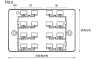
- FIG. 2 is a plan view showing a configuration of a planar antenna in monitoring apparatus 100 according to the first embodiment.
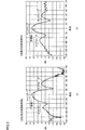
- FIG. 3 is a diagram showing the directivity characteristics of the planar antenna according to the first embodiment. Specifically, FIG. 3A is a diagram showing the directivity characteristic (pattern) in the azimuth (horizontal) direction, and FIG. 3B is a diagram showing the directivity pattern in the elevation (vertical) direction. It is.
- the planar antenna in monitoring apparatus 100 includes a transmission antenna 25 and a reception antenna 30.
- Each of the transmission antenna 25 and the reception antenna 30 has eight antenna elements.
- the directivity pattern of the planar antenna has a main lobe and two side lobes for each of the azimuth and elevation directions.
- the 3 dB beam width (half-value width) of the main lobe is ⁇ 15 degrees.
- the half width of the main lobe is preferably ⁇ 20 degrees or less.
- the configuration in which the bedding is a bed will be described, but the configuration is not limited thereto, and the bedding may be a futon or the like.
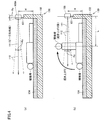
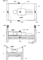
- FIG. 4 is a diagram for explaining an installation method of monitoring apparatus 100 according to the first embodiment.
- monitoring apparatus 100 is attached to body 132 of bed 130 at a height H from mat 134 of about 60 cm to 70 cm using pole 101.
- the monitoring device 100 is attached to the subject's foot side.
- the peak direction of the main lobe of the planar antenna (transmitting antenna 25 and receiving antenna 30) of the monitoring device 100 is horizontal. Therefore, when the subject is lying on the bed 130, the subject does not exist on the peak direction line 111 (virtual line) (see FIG. 4A). It should be noted that the subject does not exist on the area line 112 indicating the spread of the half width of the main lobe of the planar antenna. On the other hand, when the subject gets up from the bed 130, the subject exists on the peak direction line 111, and the subject approaches the monitoring device 100 (that is, with the monitoring device 100). The distance L with the subject is shortened). Therefore, the amplitude of the reflected signal reflected by the subject and input to the receiving antenna 30 is significantly increased.
- a side lobe exists in the directivity pattern of the planar antenna in the monitoring apparatus 100. For this reason, even when the subject is lying down and turns over to the left and right, the amplitude of the reflected signal is somewhat larger, but the amplitude is smaller than when the subject is awake. Therefore, by comparing the absolute value of the amplitude of the reflected signal with a predetermined threshold value, it is possible to distinguish and monitor the state in which the subject is up and the state in which the subject is lying (including turning over). .
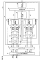
- FIG. 5 is a block diagram for illustrating a detailed configuration of the control circuit according to the first embodiment.
- control circuit 152 includes analog signal processing circuit 41, AD converter 43, and microprocessor 45.
- the microprocessor 45 is a digital signal processor (DSP) specialized for digital signal processing.
- DSP digital signal processor
- the analog signal processing circuit 41 removes unnecessary frequency band components from the signal input from the microwave Doppler sensor 160 and outputs the signal to the AD converter 43. Specifically, the analog signal processing circuit 41 outputs an I-channel analog signal Shi and a Q-channel analog signal Shq in a heart rate component band (0.7 Hz to 20 Hz), and a body motion component band (0.1 Hz). ⁇ 40 Hz) I channel analog signal Sti and Q channel analog signal Stq.
- the band of the body motion component includes the band of the heartbeat component.
- the AD converter 43 performs 16-bit (or 12-bit) AD conversion on the input signal. Specifically, the AD converter 43 receives input of the analog signals Shi, Shq, Sti, Stq, and converts the analog signals Shi, Shq, Sti, Stq into digital signals at a predetermined sampling rate (for example, 10 msec). And output to the microprocessor 45. Each digital signal Shi, Shq, Sti, Stq is appropriately offset adjusted as a ⁇ signal according to the voltage amplitude.
- the microprocessor 45 executes various processes using the digital signals Shi, Shq, Sti, Stq. Specifically, the microprocessor 45 includes a rising determination unit 50, a state determination unit 52, an output control unit 54, a heart rate calculation unit 60, and a respiration calculation unit 70 as main functional configurations.
- the heartbeat calculation unit 60 receives various digital signals Shi and Shq and executes various processes.
- the heart rate calculator 60 includes an I channel high pass filter (HPF) 64I, a Q channel HPF 64Q, an I channel LPF 65I, a Q channel LPF 65Q, and an I channel fundamental. It includes a detection unit 66I, a Q channel side fundamental wave detection unit 66Q, and a heart rate average processing unit 67.
- HPF high pass filter
- the HPFs 64I and 64Q generate digital signals Hai and Haq by removing low frequency components (particularly, the respiration component band) of the digital signals Shi and Shq, respectively.
- the HPF 64I outputs the digital signal Hai to the LPF 65I
- the HPF 64Q outputs the digital signal Haq to the LPF 65Q.
- the HPFs 64I and 64Q remove frequency components of 0.7 Hz (that is, equivalent to 42 bpm) or less.
- LPFs 65I and 65Q generate digital signals Hbi and Hbq by removing high-frequency components of digital signals Hai and Haq, respectively.
- the LPF 65I outputs the digital signal Hbi to the fundamental wave detection unit 66I
- the LPF 65Q outputs the digital signal Hbq to the fundamental wave detection unit 66Q.
- the LPFs 65I and 65Q remove frequency components of 10 Hz or more.
- the LPFs 65I and 65Q may be configured to remove frequency components of 4 Hz (that is, equivalent to 240 bpm) or more.
- the fundamental wave detectors 66I and 66Q calculate the heart rate using the digital signals Hbi and Hbq, respectively. Specifically, the fundamental wave detection unit 66I performs fast Fourier transform (FFT) on the digital signal Hbi accumulated for a predetermined time (for example, 30 seconds), decomposes it into individual signal components, and then each component. Is processed on the frequency spectrum to generate frequency distribution data. The fundamental wave detection unit 66I selects a frequency distribution (eg, 0.7 Hz to 4 Hz) in a predetermined range related to the heartbeat from the frequency distribution data, and selects the frequency component having the highest intensity (peak) from among the frequency distributions. Detect as data. Note that the fundamental wave detectors 66I and 66Q may detect fundamental wave data using an autocorrelation function.
- FFT fast Fourier transform
- the fundamental wave detection unit 66I calculates the heart rate Hi, which is the number of heartbeats per unit time (ie, 1 minute), by multiplying the fundamental wave data by 60 times. Similarly, the fundamental wave detection unit 66Q calculates the heart rate Hq using the digital signal Hbq.
- the heart rate average processing unit 67 calculates a heart rate Hn by averaging the heart rate Hi and the heart rate Hq.
- the heartbeat average processing unit 67 may remove a signal with a low noise level intensity or a signal with poor periodicity by integrating the digital signals Hbi and Hbq and appropriately setting a threshold value.
- Respiration calculation unit 70 receives input of each digital signal Sti, Stq and executes various processes. Specifically, the respiratory calculation unit 70 includes an LPF 71I on the I channel side, an LPF 71Q on the Q channel side, a fundamental wave detection unit 72I on the I channel side, a fundamental wave detection unit 72Q on the Q channel side, and a respiratory average process Part 73.
- LPFs 71I and 71Q generate digital signals Bai and Baq by removing high-frequency components of digital signals Sti and Stq, respectively.
- the LPF 71I outputs the digital signal Bai to the fundamental wave detection unit 72I
- the LPF 71Q outputs the digital signal Baq to the fundamental wave detection unit 72Q.
- the LPFs 71I and 71Q remove frequency components of 0.75 Hz or higher (that is, equivalent to 45 bpm).
- the fundamental wave detection units 72I and 72Q calculate the respiration rate using the digital signals Bai and Baq, respectively.
- the fundamental wave detection unit 72I calculates the respiration rate by the same calculation method as the calculation method by the fundamental wave detection unit 66I.
- the fundamental wave detection unit 72I creates frequency distribution data by performing a fast Fourier transform on the digital signal Bai accumulated for a predetermined time.
- the fundamental wave detection unit 72I detects, as fundamental wave data, a frequency component having the highest intensity from a frequency distribution (for example, 0 Hz to 0.75 Hz) in a predetermined range related to respiration among the frequency distribution data.
- the fundamental wave detection unit 72I multiplies fundamental wave data by 60 to calculate a respiration rate Bi that is the number of breaths per unit time (that is, 1 minute). Similarly, the fundamental wave detection unit 72Q calculates the respiration rate Bq using the digital signal Baq.
- the respiration average processing unit 73 calculates the respiration rate Bn by averaging the respiration rate Bi and the respiration rate Bq. Note that the breathing average processing unit 73 may remove signals with low noise level intensity and signals with poor periodicity by integrating the digital signals Bai and Baq and appropriately setting a threshold value.
- the rising determination unit 50 determines whether or not the subject has risen from the bedding based on a predetermined threshold value and a reflection signal (specifically, each digital signal Sti, Stq).
- the threshold value is a digital value when the amplitude values (voltages 0 V to 3.3 V) of the analog signals Sti and Stq are AD-converted.
- the rising determination unit 50 calculates the magnitude (absolute value) of the amplitude of each of the digital signals Sti and Stq every predetermined time (for example, 0.2 seconds). For example, when the sampling frequency is 100 Hz, the rising determination unit 50 samples the digital signal every 10 milliseconds for each of the digital signals Sti and Stq, and averages the absolute values of the sampling data for 20 samples. (Average absolute value) is calculated. The rising determination unit 50 calculates the calculated average absolute value at regular intervals, and sequentially stores the calculation results in association with the time.
- the rising determination unit 50 determines that the subject has risen from the bedding when both the average absolute value for the digital signal Sti and the average absolute value for the digital signal Stq are equal to or greater than the threshold Th1. Further, the rising determination unit 50 may determine that the subject has risen from the bedding when the average absolute value of at least one of the digital signals Sti and Stq is equal to or greater than the threshold Th1. Alternatively, the rising determination unit 50 calculates a combined signal of the digital signals Sti and Stq, and determines that the subject has risen from the bedding when the average absolute value of the combined component is equal to or greater than the threshold Th1. Good.
- the rising determination unit 50 avoids erroneous determination due to noise components, and the subject is placed in the bedding when the average absolute value is equal to or greater than the threshold value Th1 for a plurality of times (for example, two times or three times). You may decide that you got up.
- the rising determination unit 50 determines whether or not the subject has risen in view of not only the magnitude of the amplitude of the reflected signal but also the phase relationship between the I channel signal and the Q channel signal of the reflected signal. Also good.
- FIG. 6 is a diagram showing a waveform of a reflected signal detected by the microwave Doppler sensor according to the first embodiment.
- an object for example, a subject
- a stop operation is performed, and further a separation operation is performed from the microwave Doppler sensor 160. Is assumed.
- the phase Pi of the I channel signal waveform is advanced with respect to the phase Pq of the Q channel signal waveform, and as the subject approaches the microwave Doppler sensor 160, The amplitude increases.
- each of the I channel signal waveform and the Q channel signal waveform changes relatively slowly with a small amplitude and a long period.
- the phase relationship between the phase Pi and the phase Pq is inverted (that is, the phase Pi is delayed with respect to the phase Pq), and the amplitude decreases as the separation occurs.
- the movement of the subject to get up from the bedding corresponds to the movement of approaching, stopping, and moving away from the monitoring device 100. Therefore, by using such characteristics, the rising determination unit 50 satisfies the condition regarding the magnitude of the amplitude of the reflected signal, and the phase of the I channel signal and the phase of the Q channel signal are inverted. In this case, it may be determined that the subject has risen from the bedding. Thereby, the determination precision of the presence or absence of a subject's rising operation can be improved.
- the various determination methods of the rising determination unit 50 as described above may be configured to be arbitrarily settable by the user.
- the state determination unit 52 determines the state of the subject based on the heart rate Hn, the respiratory rate Bn, and the determination result of the rising determination unit 50.
- the monitoring device 100 is attached substantially horizontally as in the example of FIG.
- the state determination unit 52 determines that each of the heart rate Hn and the respiratory rate Bn is out of the reference range.
- the subject is not determined to be in an abnormal state.
- the reference range Xh of the heart rate Hn is 50 to 90 times / minute
- the reference range Xb of the respiration rate Bn is 10 to 20 times / minute.
- the state determination unit 52 determines that the subject is abnormal when at least one of the heart rate Hn and the respiration rate Bn is out of the reference range when the rising determination unit 50 determines that the subject is rising. It is determined that it is in a state. For example, when the heart rate Hn is outside the reference range Xh, the state determination unit 52 determines that the heart rate is abnormal, and when the respiratory rate Bn is outside the reference range Xb, the state determination unit 52 determines that the respiratory abnormality is present. To do.
- the output control unit 54 outputs warning information based on the determination results of the rising determination unit 50 and the state determination unit 52. Specifically, the output control unit 54 outputs warning information when receiving a determination result that the subject has been awakened and a determination result that is a heartbeat abnormality or respiratory abnormality.
- the output control unit 54 may output the warning information through the speaker 156 or may display the warning information on a display. Further, the output control unit 54 may transmit warning information to the terminal device 200 via the communication interface 158.
- the output control unit 54 when the subject gets up, the output control unit 54 outputs a message such as “Please do not get out of bed yet” as warning information, or indicates that the subject has risen as warning information. Information is transmitted to the terminal device 200.
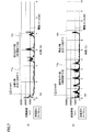
- FIG. 7 is a diagram showing an embodiment when the monitoring device 100 is installed as shown in FIG. Specifically, FIG. 7A shows an embodiment in which the monitoring device 100 is installed at a position where the height H from the mat 134 is 60 cm. FIG.7 (b) has shown the Example when the monitoring apparatus 100 is installed in the position whose height H is 70 cm.
- the horizontal axis represents time (minutes), and the vertical axis represents the magnitude of the reflected signal (specifically, the digital signals Sti, Stq) (body movement amplitude).
- the unit of the magnitude of the amplitude is an arbitrary unit (au) and indicates the intensity amplitude (corresponding to the voltage component) of the reflected signal from the subject. However, since it is a Doppler signal, it moves to the subject. When there is no value, the value is zero.
- the sampling frequency of the monitoring device 100 is 100 Hz, and the absolute value of the body motion amplitude is plotted every certain time (0.2 seconds). The plotted value is an average value (average absolute value) of absolute values of 20 pieces of sampling data.
- FIG. 7 (a) shows the time variation of the body motion amplitude when the subject performs the following operations. Specifically, in the period T1a, the subject performs a turnover operation twice every about 15 seconds from the time tsa which is the start time point, and then performs a rising operation every 10 seconds in the period T2a. Implement once.
- the body motion amplitude is larger during the rising motion than during the rolling motion.
- the threshold value Th1 is set to 10,000
- the body motion amplitude is equal to or less than the threshold value during the turning operation
- the body motion amplitude is equal to or greater than the threshold value during the rising motion, so that the rising motion and the rolling motion can be distinguished. That is, the monitoring device 100 can accurately determine the rising motion of the subject. For example, the monitoring apparatus 100 may determine that the subject has risen when the plot value is continuously equal to or greater than the threshold value (10000) twice or more. In this case, erroneous determination due to noise components can be avoided.
- the monitoring apparatus 100 determines that it has risen, the determination time is recorded together with the determination result, and information (message or the like) that prompts the subject to pay attention is output as a voice.
- the monitoring apparatus 100 transmits information indicating that the subject is in a standing state to the terminal apparatus 200. As a result, the patient can be prevented from falling from the bed 130, and the caregiver can quickly reach the subject.
- FIG. 7 (b) shows changes over time in body motion amplitude when the subject performs the following actions. Specifically, in the period T1b, the subject performs the rising operation about 10 seconds from the time tsb which is the start time, and then performs the turning operation twice on the left and right in the period T2b.
- the body motion amplitude is less than or equal to the threshold value during the turning operation, and the body motion amplitude is greater than or equal to the threshold value during the waking operation. it can.
- the subject's rising motion and the turning motion can be distinguished, so that the rising motion can be accurately determined.
- warning information for warning is output and information indicating the wake-up operation is transmitted to an external device. Therefore, it is possible to prevent the subject from falling from the bedding.
- the caregiver can quickly reach the subject.
- abnormalities in the respiratory rate and heart rate of the subject can be detected.
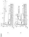
- FIG. 8 is a diagram for explaining an installation method of monitoring apparatus 100 according to the second embodiment.
- the installation method shown in FIG. 8 and the installation method described in FIG. 4 are different in angle Rc, and the other configurations are the same.
- the angle Rc 18 degrees.
- the angle Rc is set to about 20 degrees at the maximum considering the height of the person.
- the subject When the subject is lying on the bed 130, the subject does not exist on the peak direction line 111 of the main lobe of the planar antenna of the monitoring device 100 (see FIG. 8A). For this reason, even if the subject turns over, the detected body motion amplitude is considered to be relatively small.
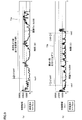
- FIG. 9 is a diagram showing a temporal change in body motion amplitude when the monitoring device 100 is installed as shown in FIG. 9A and 9B, the horizontal axis represents time (minutes), and the vertical axis represents the magnitude of body motion amplitude.
- the unit of the magnitude of the amplitude is an arbitrary unit (au).
- the sampling frequency of the monitoring device 100 is 100 Hz, and the absolute value of the body motion amplitude is plotted every certain time (0.2 seconds).
- the plotted value is an average value (average absolute value) of absolute values of 20 pieces of sampling data.
- FIG. 9 (a) shows the time variation of the body motion amplitude when the subject rises every several tens of seconds from the time tsa1 which is the start time and performs the motion three times in the period T3a.
- FIG. 9 (b) shows the time change of the body motion amplitude when the subject performs the turning action twice every left and right every several tens of seconds in the period T3b (time tsb1 to time tsb2). Yes.
- the body motion amplitude is larger in the rising motion than in the rolling motion.
- the threshold value Th1 is set larger than the example of FIG. Specifically, when the threshold value Th1 is set to 16000, the body movement amplitude is equal to or less than the threshold value during the turnover operation, and the body movement amplitude is equal to or greater than the threshold value during the rising operation, so that the rising operation and the turnover operation can be distinguished. That is, the monitoring device 100 can accurately determine the rising motion of the subject. For example, the monitoring apparatus 100 may determine that the subject has risen when the plot value is continuously equal to or greater than the threshold value (16000) five times or more. In this case, it is possible to avoid erroneous determination due to a noise component and erroneous determination of a turnover operation as a rising operation.
- the state determination unit 52 determines that the subject is in an abnormal state when at least one of the heart rate Hn and the respiratory rate Bn is out of the reference range. You may judge. If the heart rate Hn (or respiratory rate Bn) is zero despite the history of getting up motion, it is highly likely that the subject has already left the bed 130. Therefore, the state determination unit 52 is a case where it is determined that the subject is awake (that is, when there is a history of a rising motion) and the heart rate Hn (or respiratory rate Bn) is zero. May determine that the subject is getting out of bed 130.
- FIG. 10 is a diagram for explaining an installation method of monitoring apparatus 100 according to the third embodiment.
- the installation method shown in FIG. 10 is different from the installation method described in FIG. 1 in that the monitoring device 100 is installed on the subject's foot side, and the value of the angle Rc is different. It is the same.
- the angle Rc is set to 10 degrees.
- the angle Rc is set to about 20 degrees at the maximum considering the height of the person.
- the subject When the subject is lying on the bed 130, the subject does not exist on the peak direction line 111 of the main lobe of the planar antenna of the monitoring device 100 (see FIG. 10A). For this reason, even if the subject turns over, the detected body motion amplitude is considered to be relatively small.
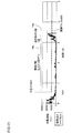
- the horizontal axis represents time (minutes), and the vertical axis represents the magnitude of body movement amplitude.
- the unit of the magnitude of the body motion amplitude is an arbitrary unit (au).
- the sampling frequency of the monitoring device 100 is 100 Hz, and the absolute value of the body motion amplitude is plotted every certain time (0.2 seconds). The plotted value is an average absolute value of 20 pieces of sampling data.
- FIG. 11 shows a case where the subject performs a turnover operation twice every left and right every several tens of seconds from the time tsa2 which is the start time point in the period T4a, and then performs a rising operation once in the period T4b.
- the time change of body motion amplitude is shown.
- the body motion amplitude is larger in the rising motion than in the rolling motion.
- the threshold value Th1 is set to 10,000
- the body movement amplitude is equal to or less than the threshold value Th1 during the turning operation
- the body movement amplitude is equal to or greater than the threshold value Th1 during the waking operation. It can be distinguished from a rollover action. That is, the monitoring device 100 can accurately determine the rising motion of the subject.
- Rc 10 degrees.
- the half width of the main lobe of the planar antenna increases.
- the third embodiment it is possible to determine the rising motion and detect the abnormality in the heart rate Hn and the respiratory rate Bn as in the first embodiment.
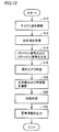
- FIG. 12 is a diagram illustrating an example of a processing procedure of the monitoring apparatus 100.
- the following steps of the monitoring apparatus 100 are mainly realized by the microprocessor 45 of the control circuit 152 executing a program stored in the memory 154.
- monitoring apparatus 100 irradiates the subject with microwaves through microwave Doppler sensor 160 (step S10).
- the monitoring apparatus 100 receives the reflected wave of the microwave via the microwave Doppler sensor 160 (step S12), and generates an I channel signal and a Q channel signal from the reflected wave signal (step S14).
- the monitoring apparatus 100 executes the determination of the rising motion of the subject using the I channel signal and the Q channel signal (step S16). Specifically, the rising determination unit 50 executes the above-described rising movement determination process. Furthermore, the monitoring apparatus 100 detects (calculates) the heart rate Hn and the respiration rate Bn of the subject using the I channel signal and the Q channel signal (step S18). Specifically, the heart rate calculation unit 60 executes the above-described heart rate calculation process, and the respiration calculation unit 70 executes the above-described respiration rate calculation process.
- the monitoring apparatus 100 determines the state of the subject based on the result of determination of rising motion, the heart rate, and the respiratory rate (step S20). Specifically, the state determination process described above is executed by the state determination unit 52. And the monitoring apparatus 100 outputs warning information based on a predetermined condition (step S22). Specifically, the output control unit 54 executes the warning information output process described above. For example, when the subject wakes up, warning information is output when it is determined that the heartbeat abnormality and respiratory abnormality are present.
- FIG. 13 is a diagram for explaining the configuration of the monitoring system according to the fourth embodiment.
- FIG. 13A is a schematic view when the subject lying on the bed 130 is viewed from above.
- FIG. 13B is a schematic view when the subject lying on the bed 130 is viewed from the side.
- FIG. 13C is a schematic view when the subject lying on the bed 130 is viewed from the head side.
- the monitoring system includes a plurality of monitoring devices 100A to 100E.
- the configuration of each of the monitoring devices 100A to 100E is substantially the same as the configuration of the monitoring device 100 described above.
- the plurality of monitoring devices 100A to 100E are configured to be able to communicate with each other.
- Each monitoring device can share these information by transmitting information such as various determination results, heart rate and respiration rate calculated by the own device to other monitoring devices.
- the monitoring system 1100 may include the terminal device 200 illustrated in FIG. In this case, each of the monitoring devices 100A to 100E is configured to be able to communicate with the terminal device 200.
- the monitoring device 100A is attached on the subject's foot side and at a height H from the mat 134 of about 60 cm to 70 cm.
- the monitoring device 100B is attached on the head side of the subject and at a height H from the mat 134 of about 60 cm to 70 cm.
- Each of the monitoring devices 100C and 100D is installed on a bedside guard 136 provided on the left and right of the main body 132 of the bed 130.
- Each of the monitoring devices 100C and 100D is attached at a height H from the mat 134 of about 20 to 30 cm.
- it is preferable that each of the monitoring devices 100C and 100D be tilted toward the subject side by an angle Rc 20 degrees so that the chest of the subject exists on the peak direction line of the main lobe of the planar antenna.
- the bedside guard 136 is installed using a dedicated stand or the like.
- each of monitoring devices 100C and 100D may be integrated with an alarm clock or the like having an appropriate height.
- the monitoring device 100E is provided between the bottom surface of the main body 132 of the bed 130 and the mat 134.
- the bedding is a futon
- the mattress is pulled under the mattress and provided between the floor (or tatami mat) and the mattress.
- the monitoring devices 100A and 100B are mainly used for determination of getting up, and the monitoring devices 100C to 100E are mainly used for detection of heartbeat, breathing and body movement (turning over) when the subject is lying down. Used. Specifically, by using at least one of the monitoring devices 100A and 100B and at least one of the monitoring devices 100C to 100E, the rising determination accuracy and the heart rate when the subject is lying down, The detection accuracy of respiration and body movement can be improved at the same time.
- a configuration in which the monitoring device 100A is used for determination of getting up and the monitoring device 100C is used for detecting heartbeat, respiration, and body movement will be described. In order to improve accuracy, a configuration using a plurality of monitoring devices 100A to 100E may be used.
- each of the monitoring devices 100A and 100C previously stores the magnitude of the body movement amplitude (noise level) when the subject is off the bed 130 and there is no moving body on the bed 130 in the internal memory.
- the magnitude of the body motion amplitude is set to the threshold Th2.
- the monitoring devices 100A and 100C determine that the average absolute value of the body motion amplitude is equal to or less than the threshold value Th2. In addition, when the determination results of the monitoring devices 100A and 100C are different, the determination result of the monitoring device 100C has priority. When the average absolute value of the body motion amplitude is equal to or less than the threshold Th2, it is highly likely that the subject is out of bed 130 or in an abnormal state.
- the monitoring device 100A further determines whether or not the subject is up and moving. Specifically, when the magnitude of the body motion amplitude is equal to or less than the threshold Th2 and there is a history of getting up (that is, when it is determined that there is a rising action), the monitoring apparatus 100A allows the subject to move to the bed 130. It is determined that you are getting out of bed. At this time, when the heart rate Hn and the respiratory rate Bn detected by the monitoring device 100C are not zero, the subject leaves the bed 130 and is in the vicinity of the bed 130 (for example, in the room). You may determine that it exists.
- the monitoring device 100A detects the subject because the magnitude of the body motion amplitude is the noise level even though the subject is present in the bed 130. It is determined that the person is in an abnormal state. In this case, the monitoring apparatus 100C may further determine whether or not the heart rate Hn and the respiration rate Bn are zero. That is, the monitoring devices 100A and 100C have a subject motion amplitude of less than or equal to the threshold Th2, there is no history of the subject rising, and the heart rate Hn and the respiratory rate Bn are zero. May be determined to be in an abnormal state.
- the monitoring devices 100A and 100C determine that the average absolute value of the body motion amplitude is larger than the threshold value Th2.
- the subject exists on the bed 130 or leaves the bed 130 and is in the vicinity of the bed 130 (for example, in the room).
- the monitoring device 100A further determines whether or not the subject is getting up, and the monitoring device 100C calculates the heart rate Hn and the respiratory rate Bn of the subject.
- the monitoring device 100A and the monitoring device 100C exist on the bed 130 in a state in which the subject is raised when there is a history of the subject rising and the heart rate Hn and the respiratory rate Bn are within the reference range. It is determined that On the other hand, the monitoring device 100A and the monitoring device 100C leave the bed 130 when the subject has a history of getting up and the heart rate Hn and the respiratory rate Bn are out of the reference range. It is determined that it exists in the vicinity.
- Monitoring device 100A and monitoring device 100C determine that the subject is lying on bed 130 when there is no history of the rising motion.
- the monitoring devices 100A and 100C can grasp the operation status of the subject around the bed 130 by the determination method as described above. Therefore, each of the monitoring devices 100A and 100C can output a message to alert the subject when he / she determines that the subject is in an abnormal state or is out of bed, Warning information is transmitted to the terminal device 200.
- the state of the subject (whether or not getting up, whether or not getting out of bed 130, and whether or not there is a physical abnormality) is determined more accurately. be able to.
- the configuration in which the monitoring device is installed in the bedding or in the vicinity thereof is described, but the configuration is not limited thereto.
- the monitoring device may be configured to be installed on a ceiling.
- each of the monitoring devices 100A and 100C compares the magnitude of the body motion amplitude with the threshold value Th2 to grasp the state of the subject more accurately has been described.
- the threshold Th2 may be used. For example, when monitoring device 100 (state determination unit 52) according to the second embodiment has a magnitude of the amplitude (body motion amplitude) of the reflected signal (digital signals Sti, Stq) equal to or smaller than threshold Th2, which is smaller than threshold Th1. It may be determined that the subject has left the bed.
- the state determination unit 52 determines that the subject is abnormal when the magnitude of the body motion amplitude is equal to or less than the threshold Th2, there is no history of the subject rising, and the heart rate Hn and the respiratory rate Bn are zero. It may be determined that the current state is not correct.
- a program for causing a computer to function and executing control is recorded on a non-temporary computer-readable recording medium such as a flexible disk attached to the computer, a CD-ROM (Compact Disk Read Only Memory), a ROM, a RAM, and a memory card as a program product. It can also be provided. Alternatively, the program can be provided by being recorded on a recording medium such as a hard disk built in the computer. A program can also be provided by downloading via a network.
- the program may be a program module that is provided as a part of an operating system (OS) of a computer and that calls necessary modules in a predetermined arrangement at a predetermined timing to execute processing.
- OS operating system
- the program itself does not include the module, and the process is executed in cooperation with the OS.
- a program that does not include such a module can also be included in the program according to the present embodiment.
- the program according to the present embodiment may be provided by being incorporated in a part of another program. Even in this case, the program itself does not include the module included in the other program, and the process is executed in cooperation with the other program. A program incorporated in such another program can also be included in the program according to the present embodiment.
- the configuration exemplified as the above-described embodiment is an example of the configuration of the present invention, and can be combined with another known technique, and a part thereof does not depart from the gist of the present invention. It is also possible to change and configure such as omitting.
Landscapes
- Health & Medical Sciences (AREA)
- Life Sciences & Earth Sciences (AREA)
- Physics & Mathematics (AREA)
- Molecular Biology (AREA)
- Animal Behavior & Ethology (AREA)
- General Physics & Mathematics (AREA)
- Biophysics (AREA)
- Pathology (AREA)
- Engineering & Computer Science (AREA)
- Biomedical Technology (AREA)
- Heart & Thoracic Surgery (AREA)
- Medical Informatics (AREA)
- Emergency Management (AREA)
- Surgery (AREA)
- Business, Economics & Management (AREA)
- General Health & Medical Sciences (AREA)
- Public Health (AREA)
- Veterinary Medicine (AREA)
- Oral & Maxillofacial Surgery (AREA)
- Physiology (AREA)
- Dentistry (AREA)
- Measurement Of The Respiration, Hearing Ability, Form, And Blood Characteristics Of Living Organisms (AREA)
- Measuring And Recording Apparatus For Diagnosis (AREA)
- Emergency Alarm Devices (AREA)
- Measuring Pulse, Heart Rate, Blood Pressure Or Blood Flow (AREA)
Abstract
被検者の起き上がり動作を適切に検出することにより、当該被検者の安全を確保することが可能な技術を提供する。寝具(130)上の被検者を監視するための監視装置(100)は、被検者に照射されたマイクロ波の反射波を受信する受信部(30)と、所定の時間間隔で、反射波の信号の振幅と第1閾値とに基づいて、被検者が起き上がったか否かを判定する起き上がり判定部(50)と、起き上がり判定部(50)により被検者が起き上がったと判定された場合に、警告情報を出力する出力制御部(54)とを備える。
Description
本開示は、監視装置に関し、特に、寝具上の被検者を監視するための監視装置に関する。本出願は、2017年1月20日に出願した日本特許出願である特願2017-008200号に基づく優先権を主張する。当該日本特許出願に記載された全ての記載内容は、参照によって本明細書に援用される。
近年、高齢化社会の進行に伴って、一人暮らしの高齢者、あるいは高齢者夫婦のみの世帯が増加している。また、過疎化等によって近隣の人々による見守りも期待できなくなり、生活をサポートする介護者等による支援にも限界があることから、高齢者や独居生活者の安否確認が十分に行えないことが多い。そのため、不測の事態発生に対する対応の遅れが頻発している。そこで、このような事態発生を防止するためにマイクロ波ドップラセンサを用いて被検者を監視するシステムが知られている。
例えば、特開2012-75861号公報(特許文献1)は、被検者の生体情報を収集して被検者の安否を監視する安否監視装置を開示している。安否監視装置は、被検者にマイクロ波を照射し、そのドップラシフトした反射波から、被検者の体動と呼吸とを検出し、所定時間内の体動数と呼吸数とから被検者の安否を監視する。
特許文献1に係る技術では、マイクロ波ドップラセンサが出力するマイクロ波ドップラシフト信号を用いて体動数および呼吸数を算出し、これらの組み合わせである安否パターンを用いて被検者の安否を監視する。
例えば、事故の具体例として、介護者が気付かないうちに、介護が必要な高齢者がベッドから離れた場合に生じ得る徘徊や転倒等が挙げられる。このような事故の発生を抑制するためには、被検者のベッド等の寝具から離床する際の起き上がりに関する動作を検出する必要がある。しかしながら、特許文献1では、被検者の当該動作を検出できないため、上記事故の発生を抑制することはできない。
本開示は、ある局面では、被検者の起き上がり動作を適切に検出することにより、当該被検者の安全を確保することが可能な監視装置を提供することを目的とする。
ある実施の形態に従うと、寝具上の被検者を監視するための監視装置が提供される。監視装置は、被検者に照射されたマイクロ波の反射波を受信する受信部と、所定の時間間隔で、反射波の信号の振幅と第1閾値とに基づいて、被検者が起き上がったか否かを判定する起き上がり判定部と、起き上がり判定部により被検者が起き上がったと判定された場合に、警告情報を出力する出力制御部とを備える。
本開示によると、被検者の起き上がり動作を適切に検出することにより、当該被検者の安全を確保することが可能となる。
以下、図面を参照しつつ、本発明の実施の形態について説明する。以下の説明では、同一の部品には同一の符号を付してある。それらの名称および機能も同じである。したがって、それらについての詳細な説明は繰り返さない。
[実施の形態1]
<システムの全体構成>
図1は、実施の形態1に従う監視システム1000の全体構成を示す図である。図1を参照して、監視システム1000は、被検者を監視するための監視装置100と、端末装置200とを含む。端末装置200は、見守り対象者である被検者を見守る側の端末であり、例えば、スマートフォンである。ただし、端末装置200は、折り畳み式携帯電話、タブレット端末装置、PC(personal computer)等のような他の機器であってもよい。
<システムの全体構成>
図1は、実施の形態1に従う監視システム1000の全体構成を示す図である。図1を参照して、監視システム1000は、被検者を監視するための監視装置100と、端末装置200とを含む。端末装置200は、見守り対象者である被検者を見守る側の端末であり、例えば、スマートフォンである。ただし、端末装置200は、折り畳み式携帯電話、タブレット端末装置、PC(personal computer)等のような他の機器であってもよい。
監視装置100と、端末装置200とを互いに接続するためのネットワーク55は、インターネット、移動体端末通信網などの各種ネットワークを含む。ネットワーク55は、これに限られず、有線通信方式を採用してもよいし、無線LAN(local area network)等のその他の無線通信方式を採用してもよい。
監視装置100は、主な構成要素として、制御回路152と、メモリ154と、スピーカ156と、通信インターフェイス158と、マイクロ波ドップラセンサ160とを含む。なお、監視装置100は、各種情報を表示するためのディスプレイと、ユーザからの各種入力を受け付けるボタン等の入力装置とを含んでいてもよい。
制御回路152は、典型的には、CPU等を含むマイクロプロセッサと、マイクロ波ドップラセンサ160からのアナログ信号を処理するアナログ信号処理回路と、ADコンバータとを含む。制御回路152の詳細な構成については後述する。マイクロプロセッサは、メモリ154に記憶されたプログラムを読み出して実行することで、監視装置100の各部の動作を制御する制御部として機能する。例えば、マイクロプロセッサは、当該プログラムを実行することによって、後述する制御回路152の処理を実現する。
メモリ154は、RAM(Random Access Memory)、ROM(Read-Only Memory)などによって実現される。メモリ154は、マイクロプロセッサによって実行されるプログラム、またはマイクロプロセッサによって用いられるデータなどを記憶する。
スピーカ156は、マイクロプロセッサから与えられる音声信号を音声に変換して監視装置100の外部へ出力する。通信インターフェイス158は、マイクロプロセッサからの通信データを符号化し通信信号に変換し、通信信号を端末装置200へ送信する。また、端末装置200から受信信号を復号化して通信データに変換しマイクロプロセッサに出力する。通信方式は、無線LANなどによる無線通信方式であってもよいし、USB(Universal Serial Bus)などを利用した有線通信方式であってもよい。
マイクロ波ドップラセンサ160は、被検者にマイクロ波を放射し、反射してきたマイクロ波から、被検者の身体の動き等を反映する信号を制御回路152に出力する。また、マイクロ波ドップラセンサ160は、入力された反射信号から、互いに直交するIチャネル信号およびQチャネル信号を生成する。
具体的には、マイクロ波ドップラセンサ160は、発振回路21と、増幅器22A,22Bと、送信アンテナ25と、受信アンテナ30と、ミキサ32I,32Qと、ローパスフィルタ(LPF)33I,33Qと、90度移相器38とを含む。送信アンテナ25および受信アンテナ30は、平面アンテナで構成されている。なお、送信アンテナ25および受信アンテナ30は、導波管アンテナ、あるいは、誘電体アンテナで構成されていてもよい。
発振回路21から出力されたマイクロ波正弦波信号は、増幅器22Aによって増幅され、送信アンテナ25から放射される。空間に放射されたマイクロ波Mtは、対象物である被検者の体表(例えば、胸部)で反射される。放射されたマイクロ波の反射波Mrには、被検者の身体の動き(体動)と、呼吸動作および心拍動作とに対応したドップラシフトが生じている。そのため、受信アンテナ30に入力される反射波Mrの信号(反射信号)は、被検者の体動、呼吸動作および心拍動作に対応した信号となる。
受信アンテナ30により受信された反射信号は、増幅器22Bによって増幅される。当該増幅後の信号Drは、Iチャネル側のミキサ32IおよびQチャネル側のミキサ32Qに入力される。ここでは、Iチャネル側に入力される信号Drを便宜上「Dri」と称し、Qチャネル側に入力される信号Drを便宜上「Drq」と称する。
増幅器22Aによって増幅された信号Dtは、Iチャネル側のミキサ32Iと、90度移相器38を介してミキサ32Qとに入力される。ここでは、Iチャネル側に入力される信号Dtを便宜上「Dti」と称し、Qチャネル側に入力される信号Dtを便宜上「Dtq」と称する。なお、本実施の形態では、90度移相器38を用いることにより、信号Dtiに対する信号Dtqの位相を90度ずらす構成について説明するが、当該構成に限られない。例えば、90度移相器38を用いることにより、信号Driに対する信号Drqの位相を90度ずらす構成であってもよい。
ミキサ32Iにより周波数変換(ダウンコンバージョン)された信号は、LPF33Iに入力される。LPF33Iは、当該信号から比較的高い周波数成分を除去した信号を、Iチャネル側のベースバンド信号Dbiとしてアナログ信号処理回路41に出力する。また、ミキサ32Qにより周波数変換された信号は、LPF33Qに入力される。LPF33Qは、当該信号から比較的高い周波数成分を除去した信号を、Qチャネル側のベースバンド信号Dbqとして制御回路152に出力する。当該ベースバンド信号Dbi,Dbqは、それぞれ、被検者の体動によって、ドップラシフトを受けたマイクロ波ドップラシフト信号として出力される。
受信アンテナ30に入力される反射信号の速度および振幅は、時間とともに変化する。そのため、Iチャネル側の信号およびQチャネル側の信号は、瞬時的には90度位相が異なっているものの、信号の速度および方向に応じて、ベースバンド信号Dbiに対するベースバンド信号Dbqの位相の進み方は、一定でなく常に時間変動することになる。
図2は、実施の形態1に従う監視装置100における平面アンテナの構成を示す平面図である。図3は、実施の形態1に従う平面アンテナの指向性特性を示す図である。具体的には、図3(a)は、方位角(水平)方向の指向性特性(パターン)を示す図であり、図3(b)は、仰角(垂直)方向の指向性パターンを示す図である。
図2を参照して、監視装置100における平面アンテナは、送信アンテナ25および受信アンテナ30を含む。送信アンテナ25および受信アンテナ30の各々は、8つのアンテナ素子を有する。
図3を参照して、平面アンテナの指向性パターンは、方位角方向および仰角方向の各々について、メインローブと2つのサイドローブとを有する。方位角方向および仰角方向の各々において、メインローブの3dBビーム幅(半値幅)は±15度である。なお、メインローブの半値幅は±20度以下であることが好ましい。
<監視装置の設置方式>
寝具の上に横たわった被検者を監視するための監視装置100の設置方式について説明する。以下では、寝具がベッドである構成について説明するが、これに限られず、寝具が布団等であってもよい。
寝具の上に横たわった被検者を監視するための監視装置100の設置方式について説明する。以下では、寝具がベッドである構成について説明するが、これに限られず、寝具が布団等であってもよい。
図4は、実施の形態1に従う監視装置100の設置方式を説明するための図である。図4を参照して、監視装置100は、ポール101を用いて、ベッド130の本体132であって、マット134からの高さH=約60cm~70cm付近に取り付けられる。図4の例では、監視装置100は、被検者の足元側に取り付けられている。また、監視装置100は、水平から所定の角度±Rcの範囲内に取り付け可能に構成される。図4の例では、Rc=0であり、監視装置100は略水平に取り付けられる。
監視装置100の平面アンテナ(送信アンテナ25および受信アンテナ30)のメインローブのピーク方向は水平である。そのため、被検者がベッド130に横たわっている場合には、ピーク方向線111(仮想的な線)上には当該被検者は存在しない(図4(a)参照)。なお、平面アンテナのメインローブの半値幅の広がりを示す領域線112上にも当該被検者は存在しない。一方、被検者がベッド130から起き上がった場合には、ピーク方向線111上に当該被検者が存在し、かつ監視装置100に被検者が接近することになる(すなわち、監視装置100と被検者との距離Lが短くなる)。そのため、被検者により反射されて受信アンテナ30に入力される反射信号の振幅は著しく大きくなる。
ここで、監視装置100における平面アンテナの指向性パターンには、サイドローブ(図3参照)が存在する。そのため、被検者が横たわっているときに左右へ寝返り動作した場合でも、反射信号の振幅は多少大きくなるが、被検者が起き上がった場合と比較すると、当該振幅は小さい。そのため、反射信号の振幅の絶対値と、所定の閾値とを比較することにより、被検者が起き上がった状態と、被検者が横たわっている状態(寝返り動作を含む)とを区別して監視できる。
<制御回路の構成>
図5は、実施の形態1に従う制御回路の詳細な構成を説明するためのブロック図である。図5を参照して、制御回路152は、アナログ信号処理回路41と、ADコンバータ43と、マイクロプロセッサ45とを含む。典型的には、マイクロプロセッサ45は、ディジタル信号処理に特化したディジタルシグナルプロセッサ(digital signal processor:DSP)である。
図5は、実施の形態1に従う制御回路の詳細な構成を説明するためのブロック図である。図5を参照して、制御回路152は、アナログ信号処理回路41と、ADコンバータ43と、マイクロプロセッサ45とを含む。典型的には、マイクロプロセッサ45は、ディジタル信号処理に特化したディジタルシグナルプロセッサ(digital signal processor:DSP)である。
アナログ信号処理回路41は、マイクロ波ドップラセンサ160から入力された信号のうちの不要な周波数帯域の成分を除去して、ADコンバータ43に出力する。具体的には、アナログ信号処理回路41は、心拍成分の帯域(0.7Hz~20Hz)のIチャネルのアナログ信号ShiおよびQチャネルのアナログ信号Shqを出力し、体動成分の帯域(0.1Hz~40Hz)のIチャネルのアナログ信号StiおよびQチャネルのアナログ信号Stqを出力する。なお、体動成分の帯域には、心拍成分の帯域も含まれる。
ADコンバータ43は、入力された信号を16ビット(または、12ビット)AD変換する。具体的には、ADコンバータ43は、アナログ信号Shi,Shq,Sti,Stqの入力を受け付け、所定のサンプリングレート(例えば、10msec)にて、アナログ信号Shi,Shq,Sti,Stqをディジタル信号に変換してマイクロプロセッサ45に出力する。なお、各ディジタル信号Shi,Shq,Sti,Stqは、電圧振幅に応じた±の信号として、適宜オフセット調整される。
マイクロプロセッサ45は、各ディジタル信号Shi,Shq,Sti,Stqを用いて各種の処理を実行する。具体的には、マイクロプロセッサ45は、主な機能構成として、起き上がり判定部50と、状態判定部52と、出力制御部54と、心拍演算部60と、呼吸演算部70とを含む。
心拍演算部60は、各ディジタル信号Shi,Shqの入力を受け付けて、各種処理を実行する。具体的には、心拍演算部60は、Iチャネル側のハイパスフィルタ(HPF)64Iと、Qチャネル側のHPF64Qと、Iチャネル側のLPF65Iと、Qチャネル側のLPF65Qと、Iチャネル側の基本波検出部66Iと、Qチャネル側の基本波検出部66Qと、心拍平均処理部67とを含む。
HPF64I,64Qは、それぞれディジタル信号Shi,Shqの低周波成分(特に、呼吸成分の帯域)を除去することにより、ディジタル信号Hai,Haqを生成する。HPF64Iは、ディジタル信号HaiをLPF65Iに出力し、HPF64Qは、ディジタル信号HaqをLPF65Qに出力する。典型的には、HPF64I,64Qは、0.7Hz(すなわち、42bpmに相当)以下の周波数成分を除去する。
LPF65I,65Qは、それぞれディジタル信号Hai,Haqの高周波成分を除去することにより、ディジタル信号Hbi,Hbqを生成する。LPF65Iは、ディジタル信号Hbiを基本波検出部66Iに出力し、LPF65Qは、ディジタル信号Hbqを基本波検出部66Qに出力する。典型的には、LPF65I,65Qは、10Hz以上の周波数成分を除去する。なお、LPF65I,65Qは、4Hz(すなわち、240bpmに相当)以上の周波数成分を除去するように構成されていてもよい。
基本波検出部66I,66Qは、それぞれディジタル信号Hbi,Hbqを用いて心拍数を演算する。具体的には、基本波検出部66Iは、所定時間(例えば、30秒)蓄積されたディジタル信号Hbiを高速フーリエ変換(FFT:Fast Fourier Transform)し、個々の信号成分に分解した後、各成分を周波数スペクトラム上に表す処理を行ない、周波数分布データを作成する。基本波検出部66Iは、周波数分布データのうち、心拍に係る所定の範囲の周波数分布(例えば、0.7Hz~4Hz)を選択し、その中から最も強度(ピーク)の高い周波数成分を基本波データとして検出する。なお、基本波検出部66I,66Qは、自己相関関数を用いて基本波データを検出してもよい。
基本波検出部66Iは、基本波データを60倍することで、単位時間(すなわち、1分間)当りの心拍の数である心拍数Hiを算出する。同様に、基本波検出部66Qは、ディジタル信号Hbqを用いて心拍数Hqを算出する。
心拍平均処理部67は、心拍数Hiおよび心拍数Hqを平均化して心拍数Hnを算出する。なお、心拍平均処理部67は、ディジタル信号Hbi,Hbqを統合して、適宜閾値を設けることにより、ノイズレベルの強度の小さい信号や周期性の乏しい信号を除去してもよい。
呼吸演算部70は、各ディジタル信号Sti,Stqの入力を受け付けて、各種処理を実行する。具体的には、呼吸演算部70は、Iチャネル側のLPF71Iと、Qチャネル側のLPF71Qと、Iチャネル側の基本波検出部72Iと、Qチャネル側の基本波検出部72Qと、呼吸平均処理部73とを含む。
LPF71I,71Qは、それぞれディジタル信号Sti,Stqの高周波成分を除去することにより、ディジタル信号Bai,Baqを生成する。LPF71Iは、ディジタル信号Baiを基本波検出部72Iに出力し、LPF71Qは、ディジタル信号Baqを基本波検出部72Qに出力する。典型的には、LPF71I,71Qは、0.75Hz以上(すなわち、45bpmに相当)の周波数成分を除去する。
基本波検出部72I,72Qは、それぞれディジタル信号Bai,Baqを用いて呼吸数を演算する。基本波検出部72Iは、基本波検出部66Iによる演算方式と同様の演算方式により呼吸数を算出する。具体的には、基本波検出部72Iは、所定時間蓄積されたディジタル信号Baiを高速フーリエ変換することにより、周波数分布データを作成する。基本波検出部72Iは、周波数分布データのうち、呼吸に係る所定の範囲の周波数分布(例えば、0Hz~0.75Hz)の中から最も強度の高い周波数成分を基本波データとして検出する。基本波検出部72Iは、基本波データを60倍することで、単位時間(すなわち、1分間)当りの呼吸の数である呼吸数Biを算出する。同様に、基本波検出部72Qは、ディジタル信号Baqを用いて呼吸数Bqを算出する。
呼吸平均処理部73は、呼吸数Biおよび呼吸数Bqを平均化して呼吸数Bnを算出する。なお、呼吸平均処理部73は、ディジタル信号Bai,Baqを統合して、適宜閾値を設けることにより、ノイズレベルの強度の小さい信号や周期性の乏しい信号を除去してもよい。
起き上がり判定部50は、所定の閾値と、反射信号(具体的には、各ディジタル信号Sti,Stq)とに基づいて、被検者が寝具から起き上がったか否かを判定する。閾値は、アナログ信号Sti,Stqの振幅値(電圧0V~3.3V)をAD変換した場合のディジタル値である。
具体的には、起き上がり判定部50は、ディジタル信号Sti,Stqの各々について、当該信号の振幅の大きさ(絶対値)を一定時間(例えば、0.2秒)ごとに算出する。例えば、サンプリング周波数が100Hzの場合には、起き上がり判定部50は、ディジタル信号Sti,Stqの各々について、当該ディジタル信号を10ミリ秒毎にサンプリングし、20個分のサンプリングデータの絶対値の平均値(平均絶対値)を算出する。起き上がり判定部50は、算出された平均絶対値を一定時間ごとに算出し、算出結果を時間と関連付けて順次記憶する。
起き上がり判定部50は、ディジタル信号Stiについての平均絶対値と、ディジタル信号Stqについての平均絶対値との両方が閾値Th1以上になった場合に、被検者が寝具から起き上がったと判定する。また、起き上がり判定部50は、ディジタル信号StiおよびStqのうちの少なくとも一方についての平均絶対値が閾値Th1以上になった場合に、被検者が寝具から起き上がったと判定してもよい。あるいは、起き上がり判定部50は、ディジタル信号StiおよびStqの合成信号を算出し、当該合成成分についての平均絶対値が閾値Th1以上になった場合に、被検者が寝具から起き上がったと判定してもよい。
また、起き上がり判定部50は、ノイズ成分による誤判定を回避するため、平均絶対値が閾値Th1以上である状態が複数回(例えば、2回または3回)連続した場合に、被検者が寝具から起き上がったと判定してもよい。
変形例として、起き上がり判定部50は、反射信号の振幅の大きさだけではなく、反射信号のIチャネル信号およびQチャネル信号の位相関係も鑑みて、被検者が起き上がったか否かを判定してもよい。
図6は、実施の形態1に従うマイクロ波ドップラセンサで検出される反射信号の波形を示す図である。ここでは、対象物(例えば、被検者)がマイクロ波ドップラセンサ160(すなわち、監視装置100)に接近動作を行なった後、停止動作を行ない、さらにマイクロ波ドップラセンサ160から離反動作を行なう場合を想定する。
図6を参照すると、接近動作中においては、Qチャネル信号波形の位相Pqに対してIチャネル信号波形の位相Piは進んでおり、被検者がマイクロ波ドップラセンサ160に接近するにつれて各信号の振幅は大きくなる。接近動作から離反動作に移る停止動作中においては、Iチャネル信号波形およびQチャネル信号波形の各々は、振幅が小さく周期が長くなり比較的緩やかに変化する。そして、離反動作中においては、位相Piおよび位相Pqの位相関係が反転し(すなわち、位相Pqに対して位相Piは遅れる)、離反するにつれて振幅は小さくなる。
被検者が寝具から起き上がる動作は、監視装置100への接近、停止、離反する動作に相当する。そのため、このような特性を利用して、起き上がり判定部50は、反射信号の振幅の大きさに関する条件を満たした場合であって、かつIチャネル信号の位相とQチャネルの信号の位相とが反転した場合に、被検者が寝具から起き上がったと判定してもよい。これにより、被検者の起き上がり動作の有無の判定精度を高めることができる。
なお、上述したような起き上がり判定部50の各種の判定方式は、ユーザにより任意に設定可能に構成されていてもよい。
状態判定部52は、心拍数Hnと、呼吸数Bnと、起き上がり判定部50の判定結果とに基づいて、被検者の状態を判定する。ここで、図4の例ように、監視装置100が略水平に取り付けられている場合を想定する。この例では、被検者が横たわっている場合には、仮に被検者が正常な状態であっても適切な心拍数Hnおよび呼吸数Bnは検出されないと考えられる。そのため、起き上がり判定部50により被検者が起き上がったと判定されていない場合には(つまり、起き上がり履歴がない)、状態判定部52は、心拍数Hnおよび呼吸数Bnの各々が基準範囲外であっても被検者が異常な状態であると判定することはない。例えば、心拍数Hnの基準範囲Xhは、50~90回/分であり、呼吸数Bnの基準範囲Xbは、10~20回/分である。
一方、被検者が起き上がっているときには、被検者が正常な状態であれば、適切な心拍数Hnおよび呼吸数Bnが検出されると考えられる。そのため、状態判定部52は、起き上がり判定部50により被検者が起き上がっていると判定された場合に、心拍数Hnおよび呼吸数Bnの少なくとも一方が基準範囲外であるときには被検者が異常な状態であると判定する。例えば、心拍数Hnが基準範囲Xh外である場合には、状態判定部52は心拍異常と判定し、呼吸数Bnが基準範囲Xb外である場合には、状態判定部52は呼吸異常と判定する。
出力制御部54は、起き上がり判定部50および状態判定部52の判定結果に基づいて、警告情報を出力する。具体的には、出力制御部54は、被検者が起き上がったとの判定結果、心拍異常および呼吸異常との判定結果を受けた場合に、警告情報を出力する。出力制御部54は、スピーカ156を介して、警告情報を音声出力してもよいし、ディスプレイに警告情報を表示してもよい。また、出力制御部54は、通信インターフェイス158を介して、端末装置200に警告情報を送信してもよい。
例えば、出力制御部54は、被検者が起き上がった場合、警告情報として「まだ、ベッドから降りないで下さい」等のメッセージを音声出力したり、警告情報として被検者が起き上がったことを示す情報を端末装置200に送信したりする。
<実施例>
図7は、図4に示すように監視装置100を設置した場合の実施例を示す図である。具体的には、図7(a)は、マット134からの高さHが60cmの位置に監視装置100が設置された場合の実施例を示している。図7(b)は、高さHが70cmの位置に監視装置100が設置された場合の実施例を示している。
図7は、図4に示すように監視装置100を設置した場合の実施例を示す図である。具体的には、図7(a)は、マット134からの高さHが60cmの位置に監視装置100が設置された場合の実施例を示している。図7(b)は、高さHが70cmの位置に監視装置100が設置された場合の実施例を示している。
図7(a),(b)の横軸は、時間(分)であり、縦軸は反射信号(具体的には、ディジタル信号Sti,Stq)の振幅(体動振幅)の大きさを示している。振幅の大きさの単位は任意単位(a.u)であり、被検者からの反射信号の強度振幅(電圧成分に相当)を示しているが、ドップラー信号であるため、被検者に動きがないときはゼロの値となる。なお、監視装置100のサンプリング周波数は100Hzであり、一定時間(0.2秒)毎に、体動振幅の絶対値をプロットしている。当該プロットされる値は、20個分のサンプリングデータの絶対値の平均値(平均絶対値)である。
図7(a)には、被検者が以下のような動作を行なった場合の体動振幅の時間変化が示されている。具体的には、被検者は、期間T1aにおいて、スタート時点である時刻tsaから約15秒毎に寝返り動作を左右2回ずつ実施した後、期間T2aにおいて、起き上がり動作を約10秒毎に3回実施する。
図7(a)を参照すると、寝返り動作時よりも起き上がり動作時の方が、体動振幅が大きいことがわかる。ここで、閾値Th1を10000に設定すると、寝返り動作時には、体動振幅が閾値以下となり、起き上がり動作時には、体動振幅が閾値以上となるため、起き上がり動作と寝返り動作とを区別できる。すなわち、監視装置100は、被検者の起き上がり動作を精度良く判定できる。例えば、監視装置100は、プロット値が2回以上連続して閾値(10000)以上となった場合に、被検者が起き上がったと判定してもよい。この場合、ノイズ成分による誤判定を回避することができる。
なお、プロット値が2回以上連続して閾値以上となった場合には、被検者がベッド上で激しく動き回っている状態か、起き上がって離床しようとしている状態である。そのため、監視装置100は、起き上がったと判定した場合には、当該判定結果とともに判定時刻を記録し、被検者に注意を促す情報(メッセージ等)を音声出力する。また、監視装置100は、被検者が起き上がった状態であることを示す情報を端末装置200に送信する。これにより、被検者のベッド130からの転倒を未然に防ぐことができるとともに、介護者がいち早く被検者の元に駆けつけることができる。
図7(b)には、被検者が以下のような動作を行なった場合の体動振幅の時間変化が示されている。具体的には、被検者は、期間T1bにおいて、スタート時点である時刻tsbから約10秒毎に起き上がり動作を5回実施した後、期間T2bにおいて、寝返り動作を左右2回ずつ実施する。
図7(b)を参照すると、閾値Th1を10000に設定した場合、寝返り動作時には体動振幅が閾値以下となり、起き上がり動作時には体動振幅が閾値以上となるため、起き上がり動作と寝返り動作とを区別できる。このように、高さH=60cmと高さH=70cmとでは、概ね同等な結果が得られる。
<利点>
実施の形態1によると、非接触で被検者の体動を検出することにより、被検者の起き上がり動作と寝返り動作とを区別できるため、起き上がり動作を精度良く判定することができる。被検者が起き上がった場合には、注意を促す警告情報が出力されるとともに、外部の装置に起き上がり動作を示す情報が送信される。そのため、寝具からの被検者の転倒を防止できるとともに。介護者がいち早く被検者の元に駆けつけることができる。また、被検者が起き上がった状態においては、被検者の呼吸数および心拍数の異常を検出することもできる。
実施の形態1によると、非接触で被検者の体動を検出することにより、被検者の起き上がり動作と寝返り動作とを区別できるため、起き上がり動作を精度良く判定することができる。被検者が起き上がった場合には、注意を促す警告情報が出力されるとともに、外部の装置に起き上がり動作を示す情報が送信される。そのため、寝具からの被検者の転倒を防止できるとともに。介護者がいち早く被検者の元に駆けつけることができる。また、被検者が起き上がった状態においては、被検者の呼吸数および心拍数の異常を検出することもできる。
[実施の形態2]
実施の形態1では、図4に示すように、監視装置100が略水平に設置される構成について説明した。実施の形態2では、監視装置100が、ベッドに横たわった被検者の方に所定角度だけ傾けて設置される構成について説明する。
実施の形態1では、図4に示すように、監視装置100が略水平に設置される構成について説明した。実施の形態2では、監視装置100が、ベッドに横たわった被検者の方に所定角度だけ傾けて設置される構成について説明する。
図8は、実施の形態2に従う監視装置100の設置方式を説明するための図である。図8に示す設置方式と、図4で説明した設置方式とは、角度Rcが異なり、それ以外の構成は同様である。具体的には、図4の例には、角度Rc=0に設定され、監視装置100が略水平に設置されていたが、図8の例では、ベッド130のマット134側(すなわち、被検者側)に角度Rc=18度ほど傾けて設置される。角度Rcは、人の身長を考慮すると、最大でも20度程度に設定される。
被検者がベッド130に横たわっている場合には、監視装置100の平面アンテナのメインローブのピーク方向線111上には当該被検者は存在しない(図8(a)参照)。そのため、被検者が寝返り動作を行なったとしても、検出される体動振幅の大きさは比較的小さいと考えられる。
一方、被検者がベッド130から起き上がった場合には、ピーク方向線111上に当該被検者が存在し、かつ監視装置100に被検者が接近することになる。そのため、検出される体動振幅は大きく上昇すると考えられる。
図9は、図8に示すように監視装置100を設置した場合の体動振幅の時間変化を示す図である。図9(a),(b)の横軸は、時間(分)であり、縦軸は体動振幅の大きさを示している。振幅の大きさの単位は任意単位(a.u)である。監視装置100のサンプリング周波数は100Hzであり、一定時間(0.2秒)毎に、体動振幅の絶対値をプロットしている。当該プロットされる値は、20個分のサンプリングデータの絶対値の平均値(平均絶対値)である。
図9(a)には、被検者が、期間T3aにおいて、スタート時点である時刻tsa1から数十秒毎に起き上がり動作を3回実施した場合の体動振幅の時間変化が示されている。図9(b)には、被検者が、期間T3b(時刻tsb1~時刻tsb2)において、数十秒毎に寝返り動作を左右2回ずつ実施した場合の体動振幅の時間変化が示されている。
図9(a)および(b)を参照すると、寝返り動作時よりも起き上がり動作時の方が、体動振幅が大きいことがわかる。また、監視装置100は、図8に示すようにRc=18度だけ被検者側に傾けて設置されている。この場合、監視装置100は、被検者の動きをより敏感に検出するため、体動振幅の大きさは、図7に示す実施例(すなわち、Rc=0度の場合の実施例)よりも大きくなっている。
そのため、図7の例よりも閾値Th1を大きく設定する。具体的には、閾値Th1を16000に設定すると、寝返り動作時には、体動振幅が閾値以下となり、起き上がり動作時には、体動振幅が閾値以上となるため、起き上がり動作と寝返り動作とを区別できる。すなわち、監視装置100は、被検者の起き上がり動作を精度良く判定できる。例えば、監視装置100は、プロット値が5回以上連続して閾値(16000)以上となった場合に、被検者が起き上がったと判定してもよい。この場合、ノイズ成分による誤判定や、寝返り動作を起き上がり動作と誤判定するのを回避できる。
また、実施の形態2では、角度Rc=18度だけ被検者側に傾けて監視装置100が設置されているため、被検者が横たわった状態であっても、平面アンテナのメインローブの半値幅の広がりを示す領域線112上に、被検者が存在する構成となる。そのため、被検者が横たわっている場合および被検者が起き上がっている場合について、被検者が正常な状態であれば適切な心拍数Hnおよび呼吸数Bnが検出されると考えられる。
このことから、起き上がり判定部50の判定結果に関わらず、状態判定部52は、心拍数Hnおよび呼吸数Bnの少なくとも一方が基準範囲外である場合には被検者が異常な状態であると判定してもよい。なお、起き上がり動作の履歴があるにも関わらず、心拍数Hn(あるいは呼吸数Bn)がゼロである場合には、被検者は既にベッド130から離床している可能性が高い。そのため、状態判定部52は、被検者が起き上がっていると判定された場合(すなわち、起き上がり動作の履歴がある場合)であって、かつ心拍数Hn(あるいは呼吸数Bn)がゼロである場合には、被検者がベッド130から離床していると判定してもよい。
<利点>
実施の形態2によると、実施の形態1の利点に加えて、被検者が横たわった状態である場合であっても、被検者の心拍数および呼吸数の異常を検出できる。
実施の形態2によると、実施の形態1の利点に加えて、被検者が横たわった状態である場合であっても、被検者の心拍数および呼吸数の異常を検出できる。
[実施の形態3]
実施の形態1では、図4に示すように、監視装置100が被検者の足元側に設置される構成について説明した。実施の形態3では、監視装置100が被検者の頭側に設置される構成について説明する。
実施の形態1では、図4に示すように、監視装置100が被検者の足元側に設置される構成について説明した。実施の形態3では、監視装置100が被検者の頭側に設置される構成について説明する。
図10は、実施の形態3に従う監視装置100の設置方式を説明するための図である。図10に示す設置方式は、図1で説明した設置方式と比較して、監視装置100が被検者の足元側に設置されている点、および角度Rcの値が異なり、それ以外の構成は同様である。具体的には、図10の例では、角度Rc=10度に設定されている。角度Rcは、人の身長を考慮すると、最大でも20度程度に設定される。
被検者がベッド130に横たわっている場合には、監視装置100の平面アンテナのメインローブのピーク方向線111上には当該被検者は存在しない(図10(a)参照)。そのため、被検者が寝返り動作を行なったとしても、検出される体動振幅の大きさは比較的小さいと考えられる。一方、被検者がベッド130から起き上がった場合には、ピーク方向線上に当該被検者が存在し、かつ監視装置100に対して被検者が概ね接近動作を行なうことになる。また、Rc=10度に設定したことによって、起き上がった状態の被検者の背中の動きを検出することができる。そのため、起き上がり動作時に検出される体動振幅は大きく上昇すると考えられる。
図11は、図10に示すように監視装置100を設置した場合の体動振幅の時間変化を示す図である。なお、監視装置100は、ベッド130のマット134からの高さH=70cm付近に取り付けられている。
図11の横軸は、時間(分)であり、縦軸は体動振幅の大きさを示している。体動振幅の大きさの単位は任意単位(a.u)である。監視装置100のサンプリング周波数は100Hzであり、一定時間(0.2秒)毎に、体動振幅の絶対値をプロットしている。当該プロットされる値は、20個分のサンプリングデータの平均絶対値である。
図11には、被検者が、期間T4aにおいて、スタート時点である時刻tsa2から数十秒毎に寝返り動作を左右2回ずつ実施した後、期間T4bにおいて、起き上がり動作を1回実施した場合の体動振幅の時間変化が示されている。
図11を参照すると、寝返り動作時よりも起き上がり動作時の方が、体動振幅が大きいことがわかる。ここで、図4の例と同様に、閾値Th1を10000に設定すると、寝返り動作時には、体動振幅が閾値Th1以下となり、起き上がり動作時には、体動振幅が閾値Th1以上となるため、起き上がり動作と寝返り動作とを区別できる。すなわち、監視装置100は、被検者の起き上がり動作を精度良く判定できる。
また、実施の形態3では、Rc=10度だけ被検者側に傾けて監視装置100が設置されているが、被検者が横たわった状態では、平面アンテナのメインローブの半値幅の広がりを示す領域線112上に、被検者が存在しない。そのため、被検者が横たわっている場合、体動振幅の大きさは、図4に示す実施例と同等となる。
したがって、実施の形態3では、実施の形態1と同様の起き上がり動作の判定、心拍数Hnおよび呼吸数Bnの異常検出が可能となる。
なお、上記では、角度Rcを10度に設定する構成について説明したが、角度Rcを20度程度に設定した場合には、被検者が横たわった状態であっても、領域線112上に、被検者が存在する構成となる。そのため、この場合には、実施の形態2と同様の起き上がり動作の判定、心拍数Hnおよび呼吸数Bnの異常検出が可能となる。
<利点>
実施の形態3によると、実施の形態1と同様の利点がある。
実施の形態3によると、実施の形態1と同様の利点がある。
[処理手順]
実施の形態1~3に係る監視装置100による処理手順について説明する。図12は、監視装置100の処理手順の一例を示す図である。以下の監視装置100の各ステップは、主に、制御回路152のマイクロプロセッサ45がメモリ154に格納されたプログラムを実行することによって実現される。
実施の形態1~3に係る監視装置100による処理手順について説明する。図12は、監視装置100の処理手順の一例を示す図である。以下の監視装置100の各ステップは、主に、制御回路152のマイクロプロセッサ45がメモリ154に格納されたプログラムを実行することによって実現される。
図12を参照して、監視装置100は、マイクロ波ドップラセンサ160を介して、マイクロ波を被検者に照射する(ステップS10)。監視装置100は、マイクロ波ドップラセンサ160を介して、マイクロ波の反射波を受信して(ステップS12)、反射波の信号からIチャネル信号およびQチャネル信号を生成する(ステップS14)。
監視装置100は、Iチャネル信号およびQチャネル信号を用いて、被検者の起き上がり動作判定を実行する(ステップS16)。具体的には、起き上がり判定部50により、上述した起き上がり動作判定処理が実行される。さらに、監視装置100は、Iチャネル信号およびQチャネル信号を用いて、被検者の心拍数Hnおよび呼吸数Bnを検出(演算)する(ステップS18)。具体的には、心拍演算部60により上述した心拍数演算処理が実行され、呼吸演算部70により上述した呼吸数演算処理が実行される。
次に、監視装置100は、起き上がり動作判定結果、心拍数および呼吸数に基づいて、被検者の状態を判定する(ステップS20)。具体的には、状態判定部52により上述した状態判定処理が実行される。そして、監視装置100は、所定の条件に基づいて、警告情報を出力する(ステップS22)。具体的には、出力制御部54により上述した警告情報の出力処理が実行される。例えば、被検者が起き上がった場合、心拍異常および呼吸異常と判定された場合に、警告情報が出力される。
[実施の形態4]
実施の形態1~3では、1つの監視装置100を用いて被検者を監視する構成について説明した。実施の形態4では、複数の監視装置100を用いて被検者を監視する構成について説明する。
実施の形態1~3では、1つの監視装置100を用いて被検者を監視する構成について説明した。実施の形態4では、複数の監視装置100を用いて被検者を監視する構成について説明する。
図13は、実施の形態4に従う監視システムの構成を説明するための図である。図13(a)は、ベッド130に横たわっている被検者を上側から見た場合の概略図である。図13(b)は、ベッド130に横たわっている被検者を横側から見た場合の概略図である。図13(c)は、ベッド130に横たわっている被検者を頭側から見た場合の概略図である。
図13を参照して、実施の形態4に従う監視システムは、複数の監視装置100A~100Eを有する。各監視装置100A~100Eの構成は、上述した監視装置100の構成と実質的に同様である。また、複数の監視装置100A~100Eは、互いに通信可能に構成されている。各監視装置は、自装置が演算した各種判定結果、心拍数および呼吸数等の情報を他の監視装置に送信することにより、これらの情報を共有できるものとする。監視システム1100は、図1に示す端末装置200を含んでいてもよい。この場合、各監視装置100A~100Eは、端末装置200と通信可能に構成される。
監視装置100Aは、被検者の足元側であって、マット134からの高さH=約60cm~70cm付近に取り付けられる。また、監視装置100Aは、被検者側に角度Rc=18度ほど傾けて設置される。監視装置100Bは、被検者の頭側であって、マット134からの高さH=約60cm~70cm付近に取り付けられる。また、監視装置100Bは、被検者側に角度Rc=10度ほど傾けて設置される。
監視装置100Cおよび100Dの各々は、ベッド130の本体132の左右に設けられたベッドサイドガード136上に設置される。各監視装置100C,100Dは、マット134からの高さH=約20~30cm付近に取り付けられる。また、各監視装置100C,100Dは、被検者側に角度Rc=20度ほど傾けることにより、平面アンテナのメインローブのピーク方向線上に被検者の胸部が存在することが好ましい。なお、寝具が布団等の場合には、ベッドサイドガード136の代わりに、専用スタンド等を用いて設置される。あるいは、監視装置100Cおよび100Dの各々は、適切な高さを有する目覚まし時計等と一体化されていてもよい。
監視装置100Eは、ベッド130の本体132の底面とマット134との間に設けられる。また、寝具が布団の場合では、敷布団の下にマットレスを引いて、床(あるいは畳)とマットレスの間に設けられる。
監視装置100Aおよび100Bは、主に、起き上がり判定用に用いられ、監視装置100C~100Eは、主に、被検者が横たわった状態のときの心拍、呼吸および体動(寝返り)の検出用に用いられる。具体的には、監視装置100Aおよび100Bのうちの少なくとも1つと、監視装置100C~100Eのうちの少なくとも1つとを用いることにより、起き上がり判定精度と、被検者が横たわった状態のときの心拍、呼吸および体動の検出精度とを同時に高めることができる。以下では、起き上がり判定用として監視装置100Aを用い、心拍、呼吸および体動検出用として監視装置100Cを用いる構成について説明する。なお、精度を高めるために、複数の監視装置100A~100Eを用いる構成であってもよい。
ここで、監視装置100Aおよび100Cの各々は、被検者がベッド130から離床しており、ベッド130上に移動体等が存在しない場合の体動振幅の大きさ(ノイズレベル)を予め内部メモリに記憶しておく。ここでは、当該体動振幅の大きさを閾値Th2に設定する。
まず、監視装置100Aおよび100Cにより、体動振幅の平均絶対値が閾値Th2以下と判定された場合について考える。なお、監視装置100Aおよび100Cの判定結果が異なる場合には、監視装置100Cの判定結果が優先される。体動振幅の平均絶対値が閾値Th2以下である場合、被検者は、ベッド130から離床しているか、異常な状態である可能性が高い。
監視装置100Aは、被検者が起き上がり動作の有無をさらに判定する。具体的には、監視装置100Aは、体動振幅の大きさが閾値Th2以下であり、かつ起き上がった履歴がある場合(すなわち、起き上がり動作ありと判定した場合)には、被検者がベッド130から離床していると判定する。なお、このとき、監視装置100Cにより検出される心拍数Hn、呼吸数Bnがゼロでない場合には、被検者は、ベッド130から離床して、当該ベッド130の近傍(例えば、部屋内)に存在すると判定してもよい。
一方、被検者が起き上がった履歴がない場合には、監視装置100Aは、被検者がベッド130に存在するにも関わらず、体動振幅の大きさがノイズレベルであることから、被検者が異常な状態であると判定する。なお、この場合、監視装置100Cは、心拍数Hn、呼吸数Bnがゼロであるか否かをさらに判定してもよい。すなわち、監視装置100Aおよび100Cは、体動振幅の大きさが閾値Th2以下であり、被検者が起き上がった履歴がなく、心拍数Hnおよび呼吸数Bnがゼロである場合には、被検者が異常な状態であると判定してもよい。
次に、監視装置100Aおよび100Cにより、体動振幅の平均絶対値が閾値Th2よりも大きいと判定された場合について考える。この場合、被検者は、ベッド130上に存在しているか、あるいは、ベッド130から離床して、当該ベッド130の近傍(例えば、部屋内)に存在する可能性が高い。
監視装置100Aは、被検者の起き上がり動作の有無をさらに判定し、監視装置100Cは、被検者の心拍数Hnおよび呼吸数Bnを演算する。監視装置100Aおよび監視装置100Cは、被検者が起き上がった履歴があり、かつ心拍数Hnおよび呼吸数Bnが基準範囲内である場合には、被検者が起き上がった状態でベッド130上に存在していると判定する。一方、監視装置100Aおよび監視装置100Cは、被検者が起き上がった履歴があり、かつ心拍数Hnおよび呼吸数Bnが基準範囲外である場合には、ベッド130から離床して、当該ベッド130の近傍に存在すると判定する。また、監視装置100Aおよび監視装置100Cは、起き上がり動作の履歴がない場合には、被検者がベッド130に横たわった状態であると判定する。
監視装置100Aおよび100Cは、上記のような判定方式により、ベッド130周囲での被検者の動作状況を把握することができる。そのため、各監視装置100Aおよび100Cは、被検者が異常な状態である、あるいは、離床している等の判定を行なった場合には、被検者に注意を促すメッセージを音声出力したり、警告情報を端末装置200に送信したりする。
<利点>
実施の形態4によると、実施の形態1~3の利点に加えて、被検者の状態(起き上がり動作の有無、ベッド130からの離床の有無、身体の異常の有無)をより精度よく判定することができる。
実施の形態4によると、実施の形態1~3の利点に加えて、被検者の状態(起き上がり動作の有無、ベッド130からの離床の有無、身体の異常の有無)をより精度よく判定することができる。
[その他の実施の形態]
(1)上述した実施の形態では、監視装置が寝具あるいはその周辺に設置される構成について説明したが、当該構成に限られない。例えば、監視装置は、天井に設置される構成であってもよい。
(1)上述した実施の形態では、監視装置が寝具あるいはその周辺に設置される構成について説明したが、当該構成に限られない。例えば、監視装置は、天井に設置される構成であってもよい。
(2)上述した実施の形態4では、監視装置100Aおよび100Cの各々が、体動振幅の大きさと閾値Th2とを比較して、被検者の状態をより精度よく把握する構成について説明した。実施の形態2でも、閾値Th2を用いるように構成されていてもよい。例えば、実施の形態2に従う監視装置100(状態判定部52)は、反射信号(ディジタル信号Sti,Stq)の振幅(体動振幅)の大きさが閾値Th1よりも小さい閾値Th2以下である場合、被検者が寝具から離床したと判定してもよい。また、状態判定部52は、体動振幅の大きさが閾値Th2以下であり、被検者が起き上がった履歴がなく、心拍数Hnおよび呼吸数Bnがゼロである場合に、被検者が異常な状態であると判定してもよい。
(3)コンピュータを機能させて、上述の実施の形態で説明したような制御を実行させるプログラムを提供することもできる。このようなプログラムは、コンピュータに付属するフレキシブルディスク、CD-ROM(Compact Disk Read Only Memory)、ROM、RAMおよびメモリカードなどの一時的でないコンピュータ読取り可能な記録媒体にて記録させて、プログラム製品として提供することもできる。あるいは、コンピュータに内蔵するハードディスクなどの記録媒体にて記録させて、プログラムを提供することもできる。また、ネットワークを介したダウンロードによって、プログラムを提供することもできる。
プログラムは、コンピュータのオペレーティングシステム(OS)の一部として提供されるプログラムモジュールのうち、必要なモジュールを所定の配列で所定のタイミングで呼出して処理を実行させるものであってもよい。その場合、プログラム自体には上記モジュールが含まれずOSと協働して処理が実行される。このようなモジュールを含まないプログラムも、本実施の形態にかかるプログラムに含まれ得る。
また、本実施の形態にかかるプログラムは他のプログラムの一部に組込まれて提供されるものであってもよい。その場合にも、プログラム自体には上記他のプログラムに含まれるモジュールが含まれず、他のプログラムと協働して処理が実行される。このような他のプログラムに組込まれたプログラムも、本実施の形態にかかるプログラムに含まれ得る。
(4)上述の実施の形態として例示した構成は、本発明の構成の一例であり、別の公知の技術と組み合わせることも可能であるし、本発明の要旨を逸脱しない範囲で、一部を省略する等、変更して構成することも可能である。
また、上述した実施の形態において、他の実施の形態で説明した処理や構成を適宜採用して実施する場合であってもよい。
今回開示された実施の形態はすべての点で例示であって制限的なものではないと考えられるべきである。本発明の範囲は、上記した説明ではなく、請求の範囲によって示され、請求の範囲と均等の意味および範囲内でのすべての変更が含まれることが意図される。
21 発振回路、22A,22B 増幅器、25 送信アンテナ、30 受信アンテナ、32I,32Q ミキサ、33I,33Q フィルタ、38 90度移相器、41 アナログ信号処理回路、43 ADコンバータ、45 マイクロプロセッサ、50 起き上がり判定部、52 状態判定部、54 出力制御部、55 ネットワーク、60 心拍演算部、66I,66Q,72I,72Q 基本波検出部、67 心拍平均処理部、70 呼吸演算部、73 呼吸平均処理部、100,100A~100E 監視装置、101 ポール、111 ピーク方向線、112 領域線、130 ベッド、132 本体、134 マット、136 ベッドサイドガード、152 制御回路、154 メモリ、156 スピーカ、158 通信インターフェイス、160 マイクロ波ドップラセンサ、200 端末装置、1000 監視システム。
Claims (7)
- 寝具上の被検者を監視するための監視装置であって、
前記被検者に照射されたマイクロ波の反射波を受信する受信部と、
所定の時間間隔で、前記反射波の信号の振幅と第1閾値とに基づいて、前記被検者が起き上がったか否かを判定する起き上がり判定部と、
前記起き上がり判定部により前記被検者が起き上がったと判定された場合に、警告情報を出力する出力制御部とを備える、監視装置。 - 前記起き上がり判定部は、前記反射波の信号の振幅の大きさが前記第1閾値以上である状態が複数回連続した場合に、前記被検者が起き上がったと判定する、請求項1に記載の監視装置。
- 前記反射波の信号から、互いに直交するIチャネル信号およびQチャネル信号を生成する信号生成部をさらに備え、
前記起き上がり判定部は、前記Iチャネル信号の振幅の大きさ、および前記Qチャネル信号の振幅の大きさの両方が前記第1閾値以上である場合であって、かつ前記Iチャネル信号の位相と前記Qチャネル信号の位相とが反転した場合に、前記被検者が起き上がったと判定する、請求項1または2に記載の監視装置。 - 前記反射波に基づいて、所定時間内の前記被検者の心拍数を演算する心拍演算部と、
前記起き上がり判定部の判定結果と、前記心拍数とに基づいて、前記被検者の状態を判定する状態判定部とをさらに備え、
前記状態判定部は、前記起き上がり判定部によって前記被検者が起き上がったと判定された場合であって、かつ前記心拍数がゼロである場合、前記被検者が前記寝具から離床したと判定する、請求項1~3のいずれか1項に記載の監視装置。 - 前記状態判定部は、前記反射波の信号の振幅の大きさが前記第1閾値よりも小さい第2閾値未満である場合、前記被検者が前記寝具から離床したと判定する、請求項4に記載の監視装置。
- 前記出力制御部は、前記被検者が前記寝具から起き上がったことを示す情報を、前記警告情報として前記監視装置と通信可能に構成された外部装置に送信する、請求項1~5のいずれか1項に記載の監視装置。
- 前記出力制御部は、前記被検者が前記寝具から起き上がったと判定された場合、前記警告情報として、注意を促す情報を前記被検者に報知する、請求項1~6のいずれか1項に記載の監視装置。
Priority Applications (1)
| Application Number | Priority Date | Filing Date | Title |
|---|---|---|---|
| JP2018562873A JP6660492B2 (ja) | 2017-01-20 | 2017-10-11 | 監視装置 |
Applications Claiming Priority (2)
| Application Number | Priority Date | Filing Date | Title |
|---|---|---|---|
| JP2017-008200 | 2017-01-20 | ||
| JP2017008200 | 2017-01-20 |
Publications (1)
| Publication Number | Publication Date |
|---|---|
| WO2018135050A1 true WO2018135050A1 (ja) | 2018-07-26 |
Family
ID=62909111
Family Applications (1)
| Application Number | Title | Priority Date | Filing Date |
|---|---|---|---|
| PCT/JP2017/036753 Ceased WO2018135050A1 (ja) | 2017-01-20 | 2017-10-11 | 監視装置 |
Country Status (2)
| Country | Link |
|---|---|
| JP (1) | JP6660492B2 (ja) |
| WO (1) | WO2018135050A1 (ja) |
Cited By (6)
| Publication number | Priority date | Publication date | Assignee | Title |
|---|---|---|---|---|
| JPWO2020071375A1 (ja) * | 2018-10-02 | 2021-09-24 | コニカミノルタ株式会社 | 状態監視装置 |
| TWI761934B (zh) * | 2020-09-01 | 2022-04-21 | 緯創資通股份有限公司 | 非接觸式動作偵測方法、動作偵測裝置以及危險情境偵測方法 |
| WO2023048132A1 (ja) * | 2021-09-22 | 2023-03-30 | 積水化学工業株式会社 | 判定システム、判定方法、判定装置及び判定プログラム |
| JP7585529B1 (ja) | 2024-01-29 | 2024-11-18 | 住友理工株式会社 | 動作判別装置 |
| JP2025529162A (ja) * | 2022-08-29 | 2025-09-04 | フラウンホファー ゲセルシャフト ツール フェールデルンク ダー アンゲヴァンテン フォルシュンク エー.ファオ. | レーダー視野に沿った体の細分に基づいて身体モデルを作成することによるバイタルパラメータの非接触記録のためのシステムおよび方法 |
| JP2026028190A (ja) * | 2024-08-06 | 2026-02-19 | 任天堂株式会社 | サウンド再生装置、サウンド再生方法、及びサウンド再生プログラム |
Citations (8)
| Publication number | Priority date | Publication date | Assignee | Title |
|---|---|---|---|---|
| JP2007167624A (ja) * | 2005-10-07 | 2007-07-05 | Yamaguchi Univ | 離床検知通報システム |
| JP2007289461A (ja) * | 2006-04-26 | 2007-11-08 | Furukawa Co Ltd | 動作検出装置 |
| JP2009005849A (ja) * | 2007-06-27 | 2009-01-15 | Nippon Telegr & Teleph Corp <Ntt> | 転倒転落事故予防装置 |
| JP2010178933A (ja) * | 2009-02-06 | 2010-08-19 | Tokyo Metropolitan Univ | 身体情報測定装置および身体情報測定システム |
| JP2010273939A (ja) * | 2009-05-29 | 2010-12-09 | Carecom Co Ltd | 徘徊検出システム |
| JP2012165979A (ja) * | 2011-02-16 | 2012-09-06 | Tokyo Metropolitan Univ | 身体情報測定装置及び身体情報測定プログラム |
| JP2016097219A (ja) * | 2014-11-26 | 2016-05-30 | 吉田 一雄 | 屋内事故回避システム |
| JP2017047078A (ja) * | 2015-09-04 | 2017-03-09 | 株式会社構造計画研究所 | 検知装置、検知方法、およびプログラム |
-
2017
- 2017-10-11 JP JP2018562873A patent/JP6660492B2/ja not_active Expired - Fee Related
- 2017-10-11 WO PCT/JP2017/036753 patent/WO2018135050A1/ja not_active Ceased
Patent Citations (8)
| Publication number | Priority date | Publication date | Assignee | Title |
|---|---|---|---|---|
| JP2007167624A (ja) * | 2005-10-07 | 2007-07-05 | Yamaguchi Univ | 離床検知通報システム |
| JP2007289461A (ja) * | 2006-04-26 | 2007-11-08 | Furukawa Co Ltd | 動作検出装置 |
| JP2009005849A (ja) * | 2007-06-27 | 2009-01-15 | Nippon Telegr & Teleph Corp <Ntt> | 転倒転落事故予防装置 |
| JP2010178933A (ja) * | 2009-02-06 | 2010-08-19 | Tokyo Metropolitan Univ | 身体情報測定装置および身体情報測定システム |
| JP2010273939A (ja) * | 2009-05-29 | 2010-12-09 | Carecom Co Ltd | 徘徊検出システム |
| JP2012165979A (ja) * | 2011-02-16 | 2012-09-06 | Tokyo Metropolitan Univ | 身体情報測定装置及び身体情報測定プログラム |
| JP2016097219A (ja) * | 2014-11-26 | 2016-05-30 | 吉田 一雄 | 屋内事故回避システム |
| JP2017047078A (ja) * | 2015-09-04 | 2017-03-09 | 株式会社構造計画研究所 | 検知装置、検知方法、およびプログラム |
Cited By (9)
| Publication number | Priority date | Publication date | Assignee | Title |
|---|---|---|---|---|
| JPWO2020071375A1 (ja) * | 2018-10-02 | 2021-09-24 | コニカミノルタ株式会社 | 状態監視装置 |
| JP7435459B2 (ja) | 2018-10-02 | 2024-02-21 | コニカミノルタ株式会社 | 状態監視装置および状態監視方法 |
| TWI761934B (zh) * | 2020-09-01 | 2022-04-21 | 緯創資通股份有限公司 | 非接觸式動作偵測方法、動作偵測裝置以及危險情境偵測方法 |
| WO2023048132A1 (ja) * | 2021-09-22 | 2023-03-30 | 積水化学工業株式会社 | 判定システム、判定方法、判定装置及び判定プログラム |
| JP7293516B1 (ja) * | 2021-09-22 | 2023-06-19 | 積水化学工業株式会社 | 判定システム、判定方法、判定装置及び判定プログラム |
| JP2025529162A (ja) * | 2022-08-29 | 2025-09-04 | フラウンホファー ゲセルシャフト ツール フェールデルンク ダー アンゲヴァンテン フォルシュンク エー.ファオ. | レーダー視野に沿った体の細分に基づいて身体モデルを作成することによるバイタルパラメータの非接触記録のためのシステムおよび方法 |
| JP7585529B1 (ja) | 2024-01-29 | 2024-11-18 | 住友理工株式会社 | 動作判別装置 |
| JP2025116481A (ja) * | 2024-01-29 | 2025-08-08 | 住友理工株式会社 | 動作判別装置 |
| JP2026028190A (ja) * | 2024-08-06 | 2026-02-19 | 任天堂株式会社 | サウンド再生装置、サウンド再生方法、及びサウンド再生プログラム |
Also Published As
| Publication number | Publication date |
|---|---|
| JPWO2018135050A1 (ja) | 2019-11-07 |
| JP6660492B2 (ja) | 2020-03-11 |
Similar Documents
| Publication | Publication Date | Title |
|---|---|---|
| WO2018135050A1 (ja) | 監視装置 | |
| JP6955425B2 (ja) | 監視装置 | |
| US10582877B2 (en) | High-frequency device | |
| US8428696B2 (en) | Ultra wideband monitoring systems and antennas | |
| JP6932090B2 (ja) | 監視装置 | |
| US7903020B2 (en) | System and methods for remote sensing using double-sideband signals | |
| JP6649635B2 (ja) | 生体監視装置、生体監視方法および生体監視システム | |
| US20100249633A1 (en) | Systems and methods for determining regularity of respiration | |
| JP7216092B2 (ja) | 心電計測システムおよび心電送信機 | |
| WO2025107550A1 (zh) | 基于毫米波雷达的多功能健康监测方法 | |
| JP2010066877A (ja) | 居住者監視システムおよび居住者監視方法 | |
| JPWO2017221745A1 (ja) | 呼吸数表示装置及び呼吸数表示方法 | |
| JP5131657B2 (ja) | 呼吸監視方法及び装置 | |
| JP2013078413A (ja) | 身体情報測定装置及び身体情報測定方法 | |
| JP7468350B2 (ja) | 状態監視装置および状態監視装置の制御方法 | |
| Obeid et al. | Doppler radar for heartbeat rate and heart rate variability extraction | |
| JP2019024742A (ja) | 計測装置、計測方法、および計測プログラム | |
| JP2012048335A (ja) | 対象者安否確認装置 | |
| JP2018067222A (ja) | 被監視者監視装置及び方法 | |
| Üncü | A 24-GHz Doppler sensor system for cardiorespiratory monitoring | |
| KR102912953B1 (ko) | 인체 감지 방법 및 인체 감지 장치 | |
| CN113729676A (zh) | 一种智能生命体征监护设备 | |
| JP2017064243A (ja) | 生体監視システム及び生体監視方法 | |
| Batchu et al. | Overnight non-contact continuous vital signs monitoring using an intelligent automatic beam-steering Doppler sensor at 2.4 GHz | |
| JP2022101213A (ja) | 生体信号処理システム、生体信号処理方法及びプログラム |
Legal Events
| Date | Code | Title | Description |
|---|---|---|---|
| 121 | Ep: the epo has been informed by wipo that ep was designated in this application |
Ref document number: 17892686 Country of ref document: EP Kind code of ref document: A1 |
|
| ENP | Entry into the national phase |
Ref document number: 2018562873 Country of ref document: JP Kind code of ref document: A |
|
| NENP | Non-entry into the national phase |
Ref country code: DE |
|
| 122 | Ep: pct application non-entry in european phase |
Ref document number: 17892686 Country of ref document: EP Kind code of ref document: A1 |