WO2018135033A1 - 空気圧制御用電磁弁ユニット - Google Patents
空気圧制御用電磁弁ユニット Download PDFInfo
- Publication number
- WO2018135033A1 WO2018135033A1 PCT/JP2017/032516 JP2017032516W WO2018135033A1 WO 2018135033 A1 WO2018135033 A1 WO 2018135033A1 JP 2017032516 W JP2017032516 W JP 2017032516W WO 2018135033 A1 WO2018135033 A1 WO 2018135033A1
- Authority
- WO
- WIPO (PCT)
- Prior art keywords
- air
- solenoid
- solenoids
- valve unit
- manifold
- Prior art date
- Legal status (The legal status is an assumption and is not a legal conclusion. Google has not performed a legal analysis and makes no representation as to the accuracy of the status listed.)
- Ceased
Links
Images




Classifications
-
- A—HUMAN NECESSITIES
- A61—MEDICAL OR VETERINARY SCIENCE; HYGIENE
- A61H—PHYSICAL THERAPY APPARATUS, e.g. DEVICES FOR LOCATING OR STIMULATING REFLEX POINTS IN THE BODY; ARTIFICIAL RESPIRATION; MASSAGE; BATHING DEVICES FOR SPECIAL THERAPEUTIC OR HYGIENIC PURPOSES OR SPECIFIC PARTS OF THE BODY
- A61H23/00—Percussion or vibration massage, e.g. using supersonic vibration; Suction-vibration massage; Massage with moving diaphragms
- A61H23/02—Percussion or vibration massage, e.g. using supersonic vibration; Suction-vibration massage; Massage with moving diaphragms with electric or magnetic drive
-
- A—HUMAN NECESSITIES
- A61—MEDICAL OR VETERINARY SCIENCE; HYGIENE
- A61H—PHYSICAL THERAPY APPARATUS, e.g. DEVICES FOR LOCATING OR STIMULATING REFLEX POINTS IN THE BODY; ARTIFICIAL RESPIRATION; MASSAGE; BATHING DEVICES FOR SPECIAL THERAPEUTIC OR HYGIENIC PURPOSES OR SPECIFIC PARTS OF THE BODY
- A61H7/00—Devices for suction-kneading massage; Devices for massaging the skin by rubbing or brushing not otherwise provided for
-
- B—PERFORMING OPERATIONS; TRANSPORTING
- B60—VEHICLES IN GENERAL
- B60N—SEATS SPECIALLY ADAPTED FOR VEHICLES; VEHICLE PASSENGER ACCOMMODATION NOT OTHERWISE PROVIDED FOR
- B60N2/00—Seats specially adapted for vehicles; Arrangement or mounting of seats in vehicles
- B60N2/64—Back-rests or cushions
- B60N2/66—Lumbar supports
-
- F—MECHANICAL ENGINEERING; LIGHTING; HEATING; WEAPONS; BLASTING
- F16—ENGINEERING ELEMENTS AND UNITS; GENERAL MEASURES FOR PRODUCING AND MAINTAINING EFFECTIVE FUNCTIONING OF MACHINES OR INSTALLATIONS; THERMAL INSULATION IN GENERAL
- F16K—VALVES; TAPS; COCKS; ACTUATING-FLOATS; DEVICES FOR VENTING OR AERATING
- F16K31/00—Actuating devices; Operating means; Releasing devices
- F16K31/02—Actuating devices; Operating means; Releasing devices electric; magnetic
- F16K31/06—Actuating devices; Operating means; Releasing devices electric; magnetic using a magnet, e.g. diaphragm valves, cutting off by means of a liquid
-
- H—ELECTRICITY
- H01—ELECTRIC ELEMENTS
- H01F—MAGNETS; INDUCTANCES; TRANSFORMERS; SELECTION OF MATERIALS FOR THEIR MAGNETIC PROPERTIES
- H01F7/00—Magnets
- H01F7/06—Electromagnets; Actuators including electromagnets
-
- H—ELECTRICITY
- H01—ELECTRIC ELEMENTS
- H01F—MAGNETS; INDUCTANCES; TRANSFORMERS; SELECTION OF MATERIALS FOR THEIR MAGNETIC PROPERTIES
- H01F7/00—Magnets
- H01F7/06—Electromagnets; Actuators including electromagnets
- H01F7/08—Electromagnets; Actuators including electromagnets with armatures
- H01F7/16—Rectilinearly-movable armatures
-
- A—HUMAN NECESSITIES
- A47—FURNITURE; DOMESTIC ARTICLES OR APPLIANCES; COFFEE MILLS; SPICE MILLS; SUCTION CLEANERS IN GENERAL
- A47C—CHAIRS; SOFAS; BEDS
- A47C27/00—Spring, stuffed or fluid mattresses or cushions specially adapted for chairs, beds or sofas
- A47C27/08—Fluid mattresses
Definitions
- the present invention relates to a solenoid valve unit for pneumatic control.
- This pneumatic control electromagnetic valve unit for example, the one described in Patent Document 1 is known.
- This pneumatic control electromagnetic valve unit includes a pair of solenoids adjacent to each other in the axial direction, and a manifold arranged between the pair of solenoids to connect them.
- Each of the solenoids has an electrical terminal.
- Each of the solenoids is electrically connected to the substrate with the terminal inserted in a through hole formed in the substrate.
- Patent Document 1 when the solenoid rotates with respect to the manifold, the extending direction of the terminal and the through direction of the through hole are shifted from each other, and it may be difficult to electrically connect the solenoid to the substrate. is there.
- An object of the present invention is to provide an electromagnetic valve unit for pneumatic control that can facilitate electrical connection between a solenoid and a substrate.
- an electromagnetic valve unit for controlling air pressure includes a solenoid, a manifold, a substrate, a first rotation restricting portion, and a second rotation restricting portion.
- the solenoid has a terminal extending in one direction.
- the manifold is connected to the manifold to form an air passage controlled by driving the solenoid.
- a through hole is formed in the substrate. The through hole penetrates the substrate in the extending direction of the terminal facing the terminal.
- the substrate is electrically connected to the solenoid with the terminal inserted into the through hole.
- the first rotation restricting portion is provided in the solenoid.
- the second rotation restricting portion is provided in the manifold and engages with the first rotation restricting portion to restrict the rotation of the solenoid with respect to the manifold.
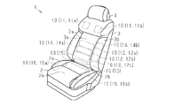
- seat apparatus with which 1st Embodiment of the solenoid valve unit for pneumatic control is applied.
- (A), (b) is a perspective view which shows the positioning structure of the solenoid by a manifold.
- seat apparatus with which 2nd Embodiment of the solenoid valve unit for air pressure control is applied.
- a seat device 1 as a seat includes a seat cushion 2 and a seat back 3 provided at a rear end portion of the seat cushion 2.
- a headrest 4 is provided at the upper end of the seat back 3.
- the seat back 3 has a shape in which both side portions 3a and 3b bulge forward.
- the seat cushion 2 has a shape in which both side portions 2a and 2b bulge upward.
- the seat device 1 has a plurality of air bags 10 (11 to 16) that change the surface shape by expanding and contracting inside the seat cushion 2 and the seat back 3.
- the seat device 1 can change the support shape by changing the surface shape with a plurality of air bags 10.
- air bags 11 (11a for independent seat support) are provided at positions corresponding to the shoulder (shoulder), waist (lumbar), and lower end (back pelvis) of the backrest surface 3s.
- 11b), 12 (12a, 12b, 12c), 13 are provided.
- independent air bags 14 (14a, 14b) for seat support are also provided at positions corresponding to both side portions 3a, 3b of the seat back 3, respectively.
- the seat cushion 2 has independent seat support air bags 15, 16 (16a, 16b) on the inner side of the rear end portion (cushion pervis) and the inner sides of both side portions 2a, 2b of the seating surface 2s. Are provided.
- the seat device 1 changes the surface shape by, for example, supplying air pumped by an air pump (not shown) into the air bags 10 or discharging the air in the air bags 10 to the outside. To do.
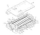
- the pneumatic control electromagnetic valve unit 20 includes a substantially rectangular box-shaped case 21 made of, for example, a resin material, and a substantially rectangular plate-shaped cover 22 made of, for example, a resin material. .
- the case 21 forms a receiving space in cooperation with the cover 22 by fitting the cover 22.
- the pair of side walls 21a and 21b extending in the longitudinal direction of the case 21 are formed with notches 21c and 21d communicating in the short direction.
- the pneumatic valve solenoid 20 for air pressure control includes a pair of manifolds 23 and 24 made of, for example, a resin material housed in a case 21.
- One manifold 23 extends in the longitudinal direction of the side wall 21 a adjacent to the side wall 21 a and is fixed to the case 21 in a fitted state.
- the manifold 23 has an air supply port 23a that protrudes to the outside of the case 21 through the notch 21c and a plurality (five) of air ports 23b, 23c, 23d, 23e, and 23f.
- the air supply port 23a is connected to an air pump and introduces the pumped air.
- Air ports 23b, 23c, 23d, 23e, and 23f are connected to air bags 12 (12b), 13, 11 (11a), 14 (14a), and 16 (16a), respectively, and supply air to them. Discharge.
- a communication passage 23g extending between the air supply port 23a and the plurality of air ports 23b to 23f is formed.
- An air supply port 23a is connected to the communication path 23g, and air pumped by an air pump is introduced.
- the other manifold 24 also extends in the longitudinal direction of the side wall 21b adjacent to the side wall 21b, and is fixed to the case 21 in a fitted state.
- the manifold 24 has a plurality (six) of air ports 24a, 24b, 24c, 24d, 24e, and 24f that protrude to the outside of the case 21 through the notches 21d.
- Air ports 24a, 24b, 24c, 24d, 24e, and 24f are connected to air bags 12 (12a), 12 (12c), 11 (11b), 14 (14b), 16 (16b), and 15 respectively. Supply and exhaust air.
- a communication path 24g extending between the plurality of air ports 24a to 24f is formed.
- the communication passage 24g is connected to a communication passage 23g of the manifold 23 through a communication passage (not shown), and air that is pressure-fed by an air pump is introduced through the communication passage 23g and the like.
- Each manifold 23, 24 is formed with a first air chamber 25 communicating with each of some of the air ports 23c-23f, 24c-24f.
- Each first air chamber 25 communicates with the communication passages 23g and 24g, and forms a valve seat 26 at the boundary with the corresponding air ports 23c to 23f and 24c to 24f. Accordingly, the air ports 23c to 23f and 24c to 24f can introduce the air pumped by the air pump through the communication passages 23g and 24g and the first air chamber 25.
- each manifold 23, 24 a second air chamber 27 communicating with each of the remaining part of the air ports 23b, 24a, 24b is formed.
- Each second air chamber 27 communicates with the communication passages 23 g and 24 g via the bypass passage 28, and forms a valve seat 29 at the boundary with the bypass passage 28. Accordingly, the air ports 23b, 24a, and 24b can introduce the air pumped by the air pump through the communication passages 23g and 24g, the bypass passage 28, and the second air chamber 27.
- the manifolds 23 and 24 are formed with substantially circular fitting recesses 23h and 24h that are expanded in accordance with the air chambers 25 and 27, respectively.
- the fitting recesses 23h and 24h are arranged concentrically with the valve seats 26 and 29.
- One manifold 23 holds a plurality (eight) solenoids 30A.
- the plurality of solenoids 30A have axes extending in parallel with each other on a plane parallel to the cover 22 and the like.
- the other manifold 24 holds a plurality (nine) of solenoids 30B.
- the plurality of solenoids 30B have axes extending in parallel with each other on the one plane.
- These solenoids 30A and 30B have the same structure.
- the solenoids 30A and 30B adjacent in the axial direction are arranged coaxially with each other in a symmetric state in the direction.
- each solenoid 30A, 30B has a substantially cylindrical bobbin 31 made of, for example, a resin material, and a winding 32 wound around and held by the bobbin 31 to generate a magnetic flux when energized.
- the bobbin 31 and the winding 32 form a coil.
- the bobbin 31 is formed with a pair of flanges 31a and 31b for preventing the winding wire 32 from coming off.
- Each solenoid 30A, 30B has a substantially cylindrical core 33 with a flange made of a magnetic material.
- the core 33 is airtightly inserted into the bobbin 31 from the flange 31a.
- each solenoid 30A, 30B has a substantially cylindrical yoke 34 with a flange made of a magnetic material. The yoke 34 is inserted into the bobbin 31 from the flange 31b.
- the flange 34a of the yoke 34 has an outer diameter equivalent to the inner diameter of the fitting recesses 23h and 24h, and is inserted into the fitting recesses 23h and 24h. That is, the solenoids 30A and 30B are connected to the manifolds 23 and 24 by inserting the flange 34a of the yoke 34 into the fitting recesses 23h and 24h.
- An O-ring (seal ring) 35 is interposed between the flange 34a and the fitting recesses 23h and 24h, and the air from the manifolds 23 and 24 (air chambers 25 and 27) is provided by the O-ring 35. Is sealed.
- an O-ring (seal ring) 36 is interposed between the flange 34a and the bobbin 31 (flange 31b), and the air from the manifolds 23 and 24 is sealed by the O-ring 36.
- Each solenoid 30A, 30B has a substantially cylindrical case 37 made of a magnetic material.
- the bobbin 31 is inserted between the flange of the core 33 and the flange 31 b of the bobbin 31.
- the case 37 holds the bobbin 31 (coil) together with the core 33 and the like.
- Each solenoid 30A, 30B has a substantially cylindrical plunger 38 made of a magnetic material.
- the plunger 38 has an outer diameter equivalent to the inner diameter of the yoke 34.
- the plunger 38 is inserted into the yoke 34 and is movable in the axial direction of the yoke 34.
- a valve body 39 made of, for example, a rubber material is fixed to the tip of the plunger 38 that protrudes from the yoke 34 into the air chambers 25 and 27.
- the valve body 39 is disposed so as to be able to contact the valve seats 26 and 29 in an airtight manner. Therefore, the movement of the plunger 38 is limited to a range until it comes into contact with the core 33 or the valve body 39 comes into contact with the valve seats 26 and 29, for example.
- the plunger 38 is urged in a direction in which the valve element 39 abuts against the valve seats 26 and 29 by a return spring 40 interposed between the plunger 38 and the plunger 34.
- each solenoid 30A, 30B has a pair of terminals 41 extending in parallel to each other in the opening direction (one direction) of the case 21 from the flange 31b of the bobbin 31. That is, both terminals 41 of all the solenoids 30A and 30B extend in the direction parallel to each other. Base ends embedded in the flanges 31 b of both terminals 41 are connected to both terminals of the winding 32.
- the first air chamber 25 communicates with the communication passages 23g and 24g into which the air pumped by the air pump is introduced.
- Each of the communication passages 23g and 24g can communicate with the outside through some solenoids 30A and 30B (the communication structure with the outside by the solenoids 30A and 30B is not shown). Accordingly, the air ports 23c to 23f and 24c to 24f can discharge air through the first air chamber 25 and the communication passages 23g and 24g.
- the second air chamber 27 can also communicate with the outside via some solenoids 30A and 30B (the communication structure with the outside by the solenoids 30A and 30B is not shown). Therefore, each air port 23 b, 24 a, 24 b can also discharge air through the second air chamber 27.
- the air pumped to the air pump is supplied into the air bag 10, or the air in the air bag 10 is discharged to the outside.
- the shape change is realized.
- the air bag 10 is shut off from the air pump and the outside, so that the surface shape of the seat device 1 can be maintained.
- the air ports 23c to 23f and 24c to 24f of the manifolds 23 and 24, the communication passages 23g and 24g, the air chambers 25 and 27, the bypass passage 28, and the like form an air passage controlled by driving the solenoids 30A and 30B.
- a holder 42 extending between the plurality of solenoids 30A and the plurality of solenoids 30B is interposed, and a spring 43 made of, for example, a leaf spring is held in the holder 42. ing.
- the spring 43 is pressed against the solenoids 30A and 30B (core 33), and is urged in a direction in which both solenoids 30A and 30B adjacent in the axial direction are separated from each other. This is to prevent the solenoids 30A and 30B from moving due to being pushed by the high-pressure air introduced into the air chambers 25 and 27.
- a substantially square plate-like substrate 45 extending along the opening of the case 21 is placed on the case 21 in which both the manifolds 23 and 24 and all the solenoids 30A and 30B are accommodated.
- a control circuit (not shown) for controlling the driving of the solenoids 30A and 30B is mounted on the substrate 45.
- a plurality of (34) through holes 46 are formed in the substrate 45 so as to face both terminals 41 of all the solenoids 30A and 30B and penetrate in the extending direction thereof.
- Each solenoid 30A, 30B is electrically connected to the substrate 45 by soldering the tip of the terminal 41 penetrating the through holes 46 in a state where both the terminals 41 are inserted into the opposing through holes 46. Connected to.
- each solenoid 30A, 30B by the manifold 23 has an axial direction from the opening end of each fitting recess 23h at a predetermined angular position (an angular position substantially matching the opening end of the case 21).
- a pair of substantially claw-shaped rotation restricting pieces 51 project in parallel to the solenoid 30A.
- the manifold 23 forms a substantially U-shaped rotation restricting groove 52 as a second rotation restricting portion between both adjacent turn restricting pieces 51.
- the part of the bobbin 31 facing the fitting recess 23h that is, the flange 31b is provided with a rotation restricting protrusion 53 as a first turn restricting part.
- the rotation restricting protrusion 53 is provided at a predetermined angular position sandwiched between both terminals 41 in the flange 31b, and protrudes in the radial direction.
- the rotation restricting protrusion 53 has a substantially quadrangular prism shape.
- the rotation restricting protrusion 53 has a circumferential width that is set to be equal to the opening width of the turn restricting groove 52 in this direction, and faces the turn restricting groove 52 on the movement path in the axial direction. .
- each solenoid 30A is positioned with respect to the manifold 23.
- each solenoid 30 ⁇ / b> A is arranged so that the extending direction of both terminals 41 coincides with the penetrating direction of the pair of through holes 46 facing both terminals 41.
- the rotation restricting protrusion 53 is inserted into the rotation restricting groove 52, whereby the rotation of each solenoid 30 ⁇ / b> A with respect to the manifold 23 is restricted.
- the rotation restricting protrusion 53 and the rotation restricting groove 52 are engaged with each other, whereby the rotation of the solenoids 30A and 30B with respect to the manifolds 23 and 24 is restricted. Therefore, the possibility that the extending direction of the terminal 41 and the penetrating direction of the through hole 46 are shifted from each other can be reduced, and the electrical connection between the solenoids 30A and 30B and the substrate 45 can be made smoother.
- the terminal 41 can be easily inserted into the through hole 46, the assembly of the substrate 45 and the like can be automated. Further, since a harness is not required for electrical connection between the solenoids 30A and 30B and the substrate 45, the overall shape can be made more compact, and the cost can be further reduced.
- the rotation restricting protrusion 53 engages with the turn restricting groove 52 at the position of the bobbin 31 (flange 31b) in which the terminal 41 is embedded, that is, at a position relatively close to the terminal 41. . Therefore, the rotation of the solenoids 30A and 30B relative to the manifolds 23 and 24 can be more efficiently regulated so that the extending direction of the terminal 41 and the penetrating direction of the through hole 46 coincide.
- the air passages of the manifolds 23 and 24 are connected to the air bag 10 for seat support that changes the support shape of the seat device 1. Therefore, the support shape of the seat device 1 can be changed by controlling the air passage connected to the air bag 10 by driving the solenoids 30A and 30B, that is, the air amount of the air bag 10.
- both terminals 41 of the plurality of solenoids 30A and 30B can be simultaneously inserted into the plurality of through holes 46 facing each other. Thereby, the electrical connection between the plurality of solenoids 30A, 30B and the substrate 45 can be further facilitated.
- the plurality of solenoids 30A and 30B are arranged along the substrate 45 and directly connected to the substrate 45, whereby the entire apparatus can be made thinner.
- Stecond Embodiment a second embodiment of the pneumatic valve solenoid valve unit will be described.
- symbol is attached
- the seat device 60 as a seat of the present embodiment repeats expansion and reduction alternately inside the seat cushion 2 and the seat back 3, thereby refreshing the seated person (massaging effect).
- a plurality of air bags 70 (70a to 70i).
- independent air bags 70 (70a to 70e) for refreshing are provided inside the seat back 3 along the backrest surface 3s.
- independent air bags 70 (70f to 70i) for refreshing are provided inside the seat cushion 2 along the seating surface 2s.
- Each of the air bags 70a to 70i has a structure in which a pair of bag portions separated on the left and right sides are integrally expanded and contracted.
- the seat device 60 alternately seats the occupant seated by repeatedly supplying the air pumped by the air pump into the air bag 70 and discharging the air in the air bag 70 to the outside. Press.
- the pneumatic control electromagnetic valve unit 80 interposed between a plurality of air bags 70 (70a to 70e) arranged on the seat back 3 and an air pump will be described.
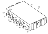
- the pneumatic control electromagnetic valve unit 80 includes a substantially rectangular box-shaped case 81 made of, for example, a resin material, and a substantially rectangular plate-shaped cover 82 made of, for example, a resin material. .
- the case 81 forms an accommodation space in cooperation with the cover 82 by fitting the cover 82.
- the side wall 81a extending in the longitudinal direction of the case 81 is formed with a notch 81b that communicates in the short direction.
- a notch 82b communicating in the short direction is also formed on the side wall 82a extending in the longitudinal direction of the cover 82 along the side wall 81a.
- the pneumatic control electromagnetic valve unit 80 includes a manifold 83 housed in a case 81 and made of, for example, a resin material.
- the manifold 83 extends in the longitudinal direction of the side walls 81 a and 82 a adjacent to the side walls 81 a and 82 a and is fixed to the case 81.
- the manifold 83 has a plurality (five) of air ports 83a, 83b, 83c, 83d, 83e and an air supply port 83f that project outside the case 81 through the notches 81b, 82b.
- the air supply port 83f is connected to an air pump and introduces the air to be pumped.
- the air ports 83a to 83e are connected to the air bags 70a to 70e, respectively, and supply and discharge air to them.
- the manifold 83 is formed with a communication passage 83g extending between the plurality of air ports 83a to 83e and the air supply port 83f.
- the communication path 83g is connected to an air supply port 83f, and introduces air to be pumped by an air pump.
- the manifold 83 is formed with an air chamber 83h communicating with each of the plurality of air ports 83a to 83e.
- the air chamber 83h communicates with the communication passage 83g, and forms a valve seat 84 at the boundary with the communication passage 83g. Accordingly, each of the air ports 83a to 83e can introduce the air pumped by the air pump through the communication passage 83g and the air chamber 83h.
- the manifold 83 is formed with a substantially circular fitting recess 83i that is expanded to match the air chamber 83h.
- the fitting recess 83 i is disposed concentrically with the valve seat 84.
- the manifold 83 holds a plurality (five) of solenoids 90.
- the plurality of solenoids 90 have axes extending in parallel with each other on a plane parallel to the cover 82 and the like.
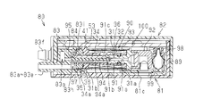
- the solenoid 90 has a substantially cylindrical core 91 with a flange made of a magnetic material.
- the core 91 is airtightly inserted into the bobbin 31 from the flange 31a.
- the core 91 is formed with an air discharge path 91a penetrating in the axial direction.
- the end of the air discharge path 91a that is away from the manifold 83 is defined as the tip.
- the front end of the air discharge path 91 a is connected to an air discharge port 81 c formed in the case 81 via a stopper 92.
- the stopper 92 is made of a magnetic material and has a substantially U-shaped cross section.
- the core 91 is formed with a substantially mortar-shaped air chamber 91b.
- the air chamber 91b is located at the tip of the core 91 near the manifold 83, and is connected to the air discharge path 91a.
- the air chamber 91b forms a valve seat 91c at the boundary with the air discharge path 91a.
- the yoke 34 inserted into the bobbin 31 from the flange 31b has a flange 34a.
- the flange 34a is fitted into the fitting recess 83i.
- the solenoid 90 has a substantially cylindrical case 93 made of a magnetic material.
- the bobbin 31 is inserted between the flange of the core 91 and the flange 31 b of the bobbin 31.
- the case 93 holds the bobbin 31 (coil) together with the core 91 and the like.
- the solenoid 90 has a substantially cylindrical plunger 94 made of a magnetic material.
- the plunger 94 has an outer diameter equivalent to the inner diameter of the yoke 34.
- the plunger 94 is inserted into the yoke 34 and is movable in the axial direction of the yoke 34.
- a communication groove 94 a is formed on the outer periphery of the plunger 94.
- the communication groove 94a extends over substantially the entire length of the plunger 94 in parallel with the axial direction.
- the communication groove 94a communicates between the air chambers 83h and 91b.
- the plunger 94 has a tip (one end) protruding from the yoke 34 into the air chamber 83h.
- a valve body 95 made of, for example, a rubber material is fixed to the tip (one end) of the plunger 94.
- the valve body 95 is disposed so as to be able to contact the valve seat 84 in an airtight manner.
- the plunger 94 has a tip (the other end) protruding into the air chamber 91b.
- a valve body 96 made of, for example, a rubber material is fixed to the tip (other end) of the plunger 94.
- the valve body 96 is disposed so as to be airtightly contactable with the valve seat 91c.
- the movement of the plunger 94 is limited to the range until the valve bodies 95 and 96 contact the valve seats 84 and 91c.
- the plunger 94 is biased in a direction in which the valve body 95 abuts on the valve seat 84 by a return spring 97 interposed between the plunger 94 and the yoke 34.
- the plunger 94 biased by the return spring 97 moves toward the valve seat 84 and comes into airtight contact with the valve seat 84.
- the valve body 96 is separated from the valve seat 91c, so that the air chamber 91b communicates with the air discharge port 81c.
- the air discharge port 81c communicates with the air ports 83a to 83e via the stopper 92, the air discharge path 91a, the air chamber 91b, the communication groove 94a, and the air chamber 83h.
- the air pumped to the air pump is supplied into the air bag 70 (70a to 70e) by driving the plurality of solenoids 90, or the air in the air bag 70 (70a to 70e) is discharged to the outside.
- the seated person of the seat device 60 is pressed in the seat back 3.
- the air ports 83a to 83e, the communication passage 83g, the air chamber 83h, and the like of the manifold 83 form an air passage controlled by driving the solenoid 90.
- a holder 98 extending between the case 81 and the stoppers 92 of the plurality of solenoids 90 is interposed, and a spring 99 made of, for example, a leaf spring is held in the holder 98.
- the spring 99 is in pressure contact with the frame 89 and the stopper 92 fixed to the case 81, and biases the solenoid 90 in the axial direction approaching the manifold 83. This is to prevent the solenoid 90 from being moved by being pushed by the high-pressure air introduced into the air chamber 83h.
- a substantially square plate-like substrate 100 extending along the opening of the case 81 is placed.
- a control circuit (not shown) for controlling the driving of the solenoid 90 is mounted on the substrate 100.
- a plurality of (ten) through holes (not shown) are formed in the substrate 100 so as to face both terminals 41 of all the solenoids 90 according to the substrate 45 and penetrate in the extending direction thereof.
- Each solenoid 90 is electrically connected to the substrate 100 by soldering the tip of the terminal 41 penetrating through the through holes in a state where both terminals 41 are inserted into the opposing through holes. .
- each solenoid 90 by the manifold 83 prior to the electrical connection between each solenoid 90 and the substrate 100 is the same as that in the first embodiment. .
- a similar air pressure control solenoid valve unit (80) is interposed between the air pumps 70 (70f to 70i) arranged on the seat cushion 2 and the air pump. Therefore, the air pumped to the air pump is supplied into the air bag 70 (70f to 70i) by driving the plurality of solenoids (90), or the air in the air bag 70 (70f to 70i) is discharged to the outside. Thus, the seat occupant of the seat device 60 is pressed in the seat cushion 2.
- the following effects can be obtained.
- the air passage connected to the air bag 70 by driving the solenoid 90, the seated person of the seat device 60 can be pressed.
- the 1st rotation control part may be provided in both the terminals 41.
- FIG. That is, in the manifolds 23, 24, and 83, instead of the both rotation restricting pieces 51 described above, substantially claw-like turn restricting pieces 111 that extend toward the solenoids 30A, 30B, and 90 in parallel with the axial direction project. Has been.
- the rotation restricting piece 111 functions as a second rotation restricting portion.
- both terminals 41 have the distance between them set equal to the circumferential width of the rotation restricting piece 111 to form the first rotation restricting portion 112.
- the rotation restriction piece 111 is inserted between the terminals 41 so that the first rotation restriction portion 112 holds the rotation restriction piece 111. (Engaged).
- the solenoids 30A, 30B, 90 are positioned with respect to the manifolds 23, 24, 83.
- the solenoids 30 ⁇ / b> A, 30 ⁇ / b> B, and 90 are arranged so that the extending direction of both terminals 41 coincides with the penetrating direction of the pair of through holes 46 facing both terminals 41. Then, by inserting the rotation restricting piece 111 into the first rotation restricting portion 112, the rotation of the solenoids 30A, 30B, 90 with respect to the manifolds 23, 24, 83 is restricted.
- the first rotation restricting portion 112 engages with the rotation restricting piece 111 at the position of the terminal 41 itself.
- the rotation of the solenoids 30A, 30B, 90 relative to the manifolds 23, 24, 83 can be more efficiently regulated so that the extending direction of the terminal 41 and the penetrating direction of the through hole 46 coincide.
- the air bag 70 for refreshing and the electromagnetic valve unit 80 for air pressure control may be mounted on the seat device 1.
- the air pumps that supply air to both types of air bags 10 and 70 one common air bag 10 or 70 may be provided, or a plurality of air pumps may be individually provided.
- the number and arrangement of the air ports (23b to 23f) of the pneumatic control solenoid valve unit 20 may be arbitrarily changed.
- the number of solenoids 30A and 30B of the pneumatic control electromagnetic valve unit 20 may be arbitrarily changed.
- the arrangement of the solenoids 30A, 30B of the pneumatic valve solenoid valve unit 20 may be arbitrarily changed as long as it has terminals (41) extending in one direction in parallel with each other.
- the number and arrangement of the air ports (83a to 83e) of the pneumatic control solenoid valve unit 80 may be arbitrarily changed.
- the number of solenoids 90 of the pneumatic control electromagnetic valve unit 80 may be arbitrarily changed.
- the arrangement of the solenoid 90 of the pneumatic control electromagnetic valve unit 80 may be arbitrarily changed as long as it has terminals (41) extending in one direction in parallel with each other.
- the base end portions of both terminals 41 may be in contact with or in close proximity to both rotation restricting pieces 51.
- the first rotation restricting portions are provided on both terminals 41 at the base end portions.
Landscapes
- Engineering & Computer Science (AREA)
- Health & Medical Sciences (AREA)
- Electromagnetism (AREA)
- Physics & Mathematics (AREA)
- Pain & Pain Management (AREA)
- Life Sciences & Earth Sciences (AREA)
- Veterinary Medicine (AREA)
- Public Health (AREA)
- General Engineering & Computer Science (AREA)
- Epidemiology (AREA)
- Power Engineering (AREA)
- Physical Education & Sports Medicine (AREA)
- Rehabilitation Therapy (AREA)
- Mechanical Engineering (AREA)
- Animal Behavior & Ethology (AREA)
- General Health & Medical Sciences (AREA)
- Transportation (AREA)
- Aviation & Aerospace Engineering (AREA)
- Dermatology (AREA)
- Magnetically Actuated Valves (AREA)
- Massaging Devices (AREA)
- Electromagnets (AREA)
Abstract
空気圧制御用電磁弁ユニットは、ソレノイドと、マニホールドと、基板と、第1回動規制部と、第2回動規制部とを含む。ソレノイドは、一方向に延伸するターミナルを有する。マニホールドにはソレノイドが連結され、ソレノイドの駆動によって制御される空気の通路を形成する。基板にはスルーホールが形成される。スルーホールはターミナルに対向してターミナルの延伸方向に基板を貫通している。基板はターミナルがスルーホールに挿入された状態でソレノイドに電気的に接続される。第1回動規制部はソレノイドに設けられる。第2回動規制部は、マニホールドに設けられ、第1回動規制部と係合してマニホールドに対するソレノイドの回動を規制する。
Description
本発明は、空気圧制御用電磁弁ユニットに関するものである。
従来、空気圧制御用電磁弁ユニットとしては、例えば特許文献1に記載されたものが知られている。この空気圧制御用電磁弁ユニットは、軸線方向で隣り合う一対のソレノイドと、該一対のソレノイドの間に配置されてそれらを連結するマニホールドとを含んでいる。ソレノイドの各々は電気的なターミナルを有している。そして、両ソレノイドの各々は、ターミナルが基板に形成されたスルーホールに挿入された状態で基板に電気的に接続されている。
ところで、特許文献1では、ソレノイドがマニホールドに対して回動すると、ターミナルの延伸方向とスルーホールの貫通方向とが互いにずれて、ソレノイドを基板に電気的に接続することが困難になる可能性がある。
本発明の目的は、ソレノイドと基板との電気的な接続をより円滑化できる空気圧制御用電磁弁ユニットを提供することにある。
上記目的を達成するため、本開示にかかる空気圧制御用電磁弁ユニットは、ソレノイドと、マニホールドと、基板と、第1回動規制部と、第2回動規制部とを含む。前記ソレノイドは、一方向に延伸するターミナルを有する。前記マニホールドには前記ソレノイドが連結され、該ソレノイドの駆動によって制御される空気の通路を形成する。前記基板にはスルーホールが形成される。前記スルーホールは前記ターミナルに対向して同ターミナルの延伸方向に前記基板を貫通している。前記基板は前記ターミナルが前記スルーホールに挿入された状態で前記ソレノイドに電気的に接続される。前記第1回動規制部は前記ソレノイドに設けられる。前記第2回動規制部は、前記マニホールドに設けられ、前記第1回動規制部と係合して前記マニホールドに対する前記ソレノイドの回動を規制する。
(第1の実施形態)
以下、空気圧制御用電磁弁ユニットの第1の実施形態について説明する。
図1に示すように、シートとしてのシート装置1は、シートクッション2と、該シートクッション2の後端部に設けられたシートバック3とを備えている。そして、シートバック3の上端には、ヘッドレスト4が設けられている。
以下、空気圧制御用電磁弁ユニットの第1の実施形態について説明する。
図1に示すように、シートとしてのシート装置1は、シートクッション2と、該シートクッション2の後端部に設けられたシートバック3とを備えている。そして、シートバック3の上端には、ヘッドレスト4が設けられている。
シートバック3は、その両サイド部3a,3bが前方に向かって膨出した形状を呈している。同様に、シートクッション2は、その両サイド部2a,2bが上方に向かって膨出した形状を呈している。これにより、シート装置1の着座者(乗員)は、良好な着座姿勢を確保し、且つ、その着座姿勢を維持することが可能になっている。
また、シート装置1は、シートクッション2及びシートバック3の内側で拡縮することにより、その表面形状を変更する複数の空気袋10(11~16)を有する。シート装置1は、複数の空気袋10により表面形状を変更することでサポート形状を変更することが可能になっている。
具体的には、シートバック3の内側において、その背もたれ面3sの肩部(ショルダ)、腰部(ランバ)及び下端部(バックペルビス)に対応する位置に、独立したシートサポート用の空気袋11(11a,11b),12(12a,12b,12c),13がそれぞれ設けられている。また、シートバック3の両サイド部3a,3bに対応する位置にも、独立したシートサポート用の空気袋14(14a,14b)がそれぞれ設けられている。さらに、シートクッション2にも、その着座面2sにおける後端部(クッションペルビス)の内側及び両サイド部2a,2bの内側に、独立したシートサポート用の空気袋15,16(16a,16b)がそれぞれ設けられている。
そして、シート装置1は、例えば空気ポンプ(図示略)により圧送された空気をこれら空気袋10内に供給し、あるいはこれら空気袋10内の空気を外部に排出させることで、その表面形状を変更する。
次に、複数の空気袋10と空気ポンプとの間に介設される空気圧制御用電磁弁ユニット20について説明する。
図2及び図3に示すように、空気圧制御用電磁弁ユニット20は、例えば樹脂材からなる略長方形の箱形のケース21と、例えば樹脂材からなる略長方形の板状のカバー22とを備える。ケース21は、カバー22が嵌着されることで該カバー22と協働して収容空間を形成する。なお、ケース21の長手方向に延びる一対の側壁21a,21bには、短手方向に連通する切り欠き21c,21dが形成されている。
図2及び図3に示すように、空気圧制御用電磁弁ユニット20は、例えば樹脂材からなる略長方形の箱形のケース21と、例えば樹脂材からなる略長方形の板状のカバー22とを備える。ケース21は、カバー22が嵌着されることで該カバー22と協働して収容空間を形成する。なお、ケース21の長手方向に延びる一対の側壁21a,21bには、短手方向に連通する切り欠き21c,21dが形成されている。
また、空気圧制御用電磁弁ユニット20は、ケース21内に収容された、例えば樹脂材からなる一対のマニホールド23,24を備える。
一方のマニホールド23は、側壁21aに隣接して側壁21aの長手方向に延在しており、ケース21に嵌合状態で固定されている。マニホールド23は、切り欠き21cを通ってケース21の外側に突出する空気供給ポート23a及び複数(5つ)の空気ポート23b,23c,23d,23e,23fを有する。空気供給ポート23aは、空気ポンプに接続されてその圧送された空気を導入する。空気ポート23b,23c,23d,23e,23fは、空気袋12(12b),13,11(11a),14(14a),16(16a)にそれぞれ接続されて、それらに対して空気を供給・排出する。
一方のマニホールド23は、側壁21aに隣接して側壁21aの長手方向に延在しており、ケース21に嵌合状態で固定されている。マニホールド23は、切り欠き21cを通ってケース21の外側に突出する空気供給ポート23a及び複数(5つ)の空気ポート23b,23c,23d,23e,23fを有する。空気供給ポート23aは、空気ポンプに接続されてその圧送された空気を導入する。空気ポート23b,23c,23d,23e,23fは、空気袋12(12b),13,11(11a),14(14a),16(16a)にそれぞれ接続されて、それらに対して空気を供給・排出する。
なお、マニホールド23には、空気供給ポート23a及び複数の空気ポート23b~23fの間に亘って延びる連通路23gが形成されている。この連通路23gには、空気供給ポート23aが接続されており、空気ポンプが圧送する空気が導入される。
他方のマニホールド24も、側壁21bに隣接して側壁21bの長手方向に延在しており、ケース21に嵌合状態で固定されている。マニホールド24は、切り欠き21dを通ってケース21の外側に突出する複数(6つ)の空気ポート24a,24b,24c,24d,24e,24fを有する。空気ポート24a,24b,24c,24d,24e,24fは、空気袋12(12a),12(12c),11(11b),14(14b),16(16b),15にそれぞれ接続されて、それらに空気を供給・排出する。
なお、マニホールド24には、複数の空気ポート24a~24fの間に亘って延びる連通路24gが形成されている。この連通路24gには、連絡通路(図示略)を介してマニホールド23の連通路23gが連絡されており、該連通路23g等を介して空気ポンプが圧送する空気が導入される。
次に、マニホールド23,24の形成する空気の通路に係る共通の内部構造について説明する。
各マニホールド23,24には、一部の空気ポート23c~23f,24c~24fの各々に連通する第1空気室25が形成されている。各第1空気室25は、連通路23g,24gに連通しており、該当の空気ポート23c~23f,24c~24fとの境界部に弁座26を形成する。従って、各空気ポート23c~23f,24c~24fは、連通路23g,24g及び第1空気室25を介して空気ポンプの圧送する空気を導入可能である。
各マニホールド23,24には、一部の空気ポート23c~23f,24c~24fの各々に連通する第1空気室25が形成されている。各第1空気室25は、連通路23g,24gに連通しており、該当の空気ポート23c~23f,24c~24fとの境界部に弁座26を形成する。従って、各空気ポート23c~23f,24c~24fは、連通路23g,24g及び第1空気室25を介して空気ポンプの圧送する空気を導入可能である。
また、各マニホールド23,24には、残りの一部の空気ポート23b,24a,24bの各々に連通する第2空気室27が形成されている。各第2空気室27は、バイパス通路28を介して連通路23g,24gに連通しており、バイパス通路28との境界部に弁座29を形成する。従って、各空気ポート23b,24a,24bは、連通路23g,24g、バイパス通路28及び第2空気室27を介して空気ポンプの圧送する空気を導入可能である。
なお、各マニホールド23,24には、空気室25,27に合わせてそれよりも拡開された略円形の嵌合凹部23h,24hが形成されている。嵌合凹部23h,24hは、弁座26,29と同心に配置されている。
一方のマニホールド23には、複数(8つ)のソレノイド30Aが保持される。複数のソレノイド30Aは、カバー22等に平行な一平面上で互いに平行に延びる軸線をそれぞれ有する。他方のマニホールド24には、複数(9つ)のソレノイド30Bが保持されている。複数のソレノイド30Bは、当該一平面上で互いに平行に延びる軸線をそれぞれ有する。これらソレノイド30A,30Bは、互いに同一の構造を有している。そして、軸線方向で隣り合う両ソレノイド30A,30Bは、当該方向で対称になる状態で互いに同軸に配置されている。
次に、各ソレノイド30A,30Bの構造について説明する。
各ソレノイド30A,30Bは、例えば樹脂材からなる略円筒状のボビン31と、該ボビン31に巻回・保持され通電によって磁束を発生させる巻き線32とを有する。ボビン31及び巻き線32はコイルを形成する。なお、ボビン31には、巻き線32を抜け止めする一対のフランジ31a,31bが形成されている。また、各ソレノイド30A,30Bは、磁性体材料からなるフランジ付き略円柱状のコア33を有する。コア33は、フランジ31aからボビン31に気密的に挿入されている。さらに、各ソレノイド30A,30Bは、磁性体材料からなるフランジ付き略円筒状のヨーク34を有する。ヨーク34は、フランジ31bからボビン31に挿入されている。
各ソレノイド30A,30Bは、例えば樹脂材からなる略円筒状のボビン31と、該ボビン31に巻回・保持され通電によって磁束を発生させる巻き線32とを有する。ボビン31及び巻き線32はコイルを形成する。なお、ボビン31には、巻き線32を抜け止めする一対のフランジ31a,31bが形成されている。また、各ソレノイド30A,30Bは、磁性体材料からなるフランジ付き略円柱状のコア33を有する。コア33は、フランジ31aからボビン31に気密的に挿入されている。さらに、各ソレノイド30A,30Bは、磁性体材料からなるフランジ付き略円筒状のヨーク34を有する。ヨーク34は、フランジ31bからボビン31に挿入されている。
なお、ヨーク34のフランジ34aは、嵌合凹部23h,24hの内径と同等の外径を有しており、該嵌合凹部23h,24hに嵌挿されている。つまり、各ソレノイド30A,30Bは、ヨーク34のフランジ34aが嵌合凹部23h,24hに嵌挿されることでマニホールド23,24に連結されている。
なお、フランジ34aと嵌合凹部23h,24hとの間にはOリング(シールリング)35が介装されており、該Oリング35によって各マニホールド23,24(空気室25,27)からの空気がシールされている。同様に、フランジ34aとボビン31(フランジ31b)との間にもOリング(シールリング)36が介装されており、該Oリング36によって各マニホールド23,24からの空気がシールされている。
各ソレノイド30A,30Bは、磁性体材料からなる略円筒状のケース37を有する。このケース37には、コア33のフランジ及びボビン31のフランジ31bの間に亘ってボビン31が挿入されている。ケース37は、コア33等と共にボビン31(コイル)を保持する。また、各ソレノイド30A,30Bは、磁性体材料からなる略円筒状のプランジャ38を有する。このプランジャ38は、ヨーク34の内径と同等の外径を有する。プランジャ38は、ヨーク34に挿入されており、ヨーク34の軸線方向に移動自在である。ヨーク34から空気室25,27内に突出するプランジャ38の先端には、例えばゴム材からなる弁体39が固着されている。この弁体39は、弁座26,29に気密的に当接可能に配置されている。従って、プランジャ38の移動は、例えばコア33に当接し、若しくは弁体39が弁座26,29に当接するまでの範囲に制限されている。なお、プランジャ38は、ヨーク34との間に介装された復帰スプリング40により、弁体39が弁座26,29に当接する方向に付勢されている。
また、各ソレノイド30A,30Bは、ボビン31のフランジ31bからケース21の開口方向(一方向)に互いに平行に延伸する一対のターミナル41を有する。つまり、全てのソレノイド30A,30Bの両ターミナル41は、互いに平行に当該方向に延伸している。両ターミナル41のフランジ31bに埋設される基端部は、巻き線32の両端子に結線されている。
このような構成にあって、両ターミナル41を通じた巻き線32への通電によって磁束が発生すると、該磁束がコア33、プランジャ38、ヨーク34及びケース37の形成する磁路を通ることでプランジャ38が復帰スプリング40の付勢力に抗してコア33に向かって引き付けられる。このとき、弁体39が弁座26から離れることで、該当の空気ポート23c~23f,24c~24fが第1空気室25に連通する。一方、巻き線32への通電が停止されると、復帰スプリング40に付勢されるプランジャ38が弁座26に向かって移動して該弁座26に気密的に当接する。これにより、該当の空気ポート23c~23f,24c~24fが第1空気室25から遮断される。
若しくは、弁体39が弁座29から離れることで、該当の空気ポート23b,24a,24bが第2空気室27に連通する。一方、巻き線32への通電が停止されると、復帰スプリング40に付勢されるプランジャ38が弁座29に向かって移動して該弁座29に気密的に当接する。これにより、該当の空気ポート23b,24a,24bが第2空気室27から遮断される。
既述のように、第1空気室25は、空気ポンプの圧送する空気の導入される連通路23g,24gに連通している。各連通路23g,24gは、一部のソレノイド30A,30Bを介して外部に連通可能でもある(当該ソレノイド30A,30Bによる外部との連通構造については図示略)。従って、各空気ポート23c~23f,24c~24fは、第1空気室25及び連通路23g,24gを介して空気を排出可能でもある。
一方、第2空気室27は、一部のソレノイド30A,30Bを介して外部に連通可能でもある(当該ソレノイド30A,30Bによる外部との連通構造については図示略)。従って、各空気ポート23b,24a,24bは、第2空気室27を介して空気を排出可能でもある。
以上により、複数のソレノイド30A,30Bの駆動によって、空気ポンプに圧送された空気が空気袋10内に供給され、あるいは空気袋10内の空気が外部に排出されることで、シート装置1の表面形状の変更が実現される。あるいは、空気ポンプ及び外部から空気袋10が遮断されることで、シート装置1の表面形状の維持が実現される。マニホールド23,24の空気ポート23c~23f,24c~24f、連通路23g,24g、空気室25,27及びバイパス通路28等は、ソレノイド30A,30Bの駆動によって制御される空気の通路を形成する。
なお、複数のソレノイド30A及び複数のソレノイド30Bの間には、それらの全体に亘って延在するホルダ42が介設されるとともに、該ホルダ42には、例えば板ばねからなるスプリング43が保持されている。このスプリング43は、ソレノイド30A,30B(コア33)に圧接されており、軸線方向で隣り合う両ソレノイド30A,30Bが互いに離間する方向に付勢される。これは、空気室25,27内に導入された高圧の空気に押されてソレノイド30A,30Bが移動することを抑制するためである。
両マニホールド23,24及び全てのソレノイド30A,30Bの収容されたケース21には、該ケース21の開口に沿って広がる略四角板状の基板45が載置される。この基板45には、これらソレノイド30A,30Bの駆動を制御する制御回路(図示略)が実装されている。基板45には、全てのソレノイド30A,30Bの両ターミナル41に対向してそれらの延伸方向に貫通する複数(34個)のスルーホール46が形成されている。各ソレノイド30A,30Bは、両ターミナル41が対向する両スルーホール46に挿入された状態で、それらスルーホール46を貫通するターミナル41の先端が基板45にハンダ付けされることで基板45に電気的に接続される。
次に、マニホールド23による各ソレノイド30A,30Bの位置決め構造について説明する。
図4及び図5(a)、(b)に示すように、マニホールド23には、各嵌合凹部23hの所定角度位置(ケース21の開口端に略一致する角度位置)の開口端から軸線方向と平行にソレノイド30Aに向かって一対の略爪状の回動規制片51が突設されている。マニホールド23は、各隣り合う両回動規制片51の間に第2回動規制部としての略U字状の回動規制溝52を形成する。
図4及び図5(a)、(b)に示すように、マニホールド23には、各嵌合凹部23hの所定角度位置(ケース21の開口端に略一致する角度位置)の開口端から軸線方向と平行にソレノイド30Aに向かって一対の略爪状の回動規制片51が突設されている。マニホールド23は、各隣り合う両回動規制片51の間に第2回動規制部としての略U字状の回動規制溝52を形成する。
一方、嵌合凹部23hに対向するボビン31の部位、すなわちフランジ31bには、第1回動規制部としての回動規制突部53が設けられている。回動規制突部53は、フランジ31bにおいて両ターミナル41の間に挟まれる所定角度位置に設けられており、径方向に突設されている。回動規制突部53は略四角柱状である。この回動規制突部53は、その周方向の幅寸法が回動規制溝52の当該方向の開口幅と同等に設定されており、軸線方向の移動軌跡上で回動規制溝52に対向する。ヨーク34のフランジ34aを嵌合凹部23hに嵌挿する際、回動規制突部53が両回動規制片51に挟持されるように回動規制溝52に挿入(係合)される。これにより各ソレノイド30Aはマニホールド23に対して位置決めされる。このとき、両ターミナル41の延伸方向と両ターミナル41に対向する一対のスルーホール46の貫通方向とが一致するように、各ソレノイド30Aは配置される。そして、回動規制突部53が回動規制溝52に挿入されることで、マニホールド23に対する各ソレノイド30Aの回動が規制される。
なお、マニホールド24による各ソレノイド30Bの位置決め構造についても同様であるため、その説明を省略する。
次に、本実施形態の作用とともに、その効果について説明する。
次に、本実施形態の作用とともに、その効果について説明する。
(1)本実施形態では、回動規制突部53及び回動規制溝52が互いに係合することで、マニホールド23,24に対する各ソレノイド30A,30Bの回動が規制される。従って、ターミナル41の延伸方向とスルーホール46の貫通方向とが互いにずれる可能性を低減でき、各ソレノイド30A,30Bと基板45との電気的な接続をより円滑化できる。また、スルーホール46に対するターミナル41の挿入が容易であることで、基板45等の組付けを自動化できる。また、各ソレノイド30A,30Bと基板45との電気的な接続にハーネスが不要であることで、その分、全体的な形状をよりコンパクト化でき、且つ、コストをより低減できる。
(2)本実施形態では、回動規制突部53は、ターミナル41を埋設するボビン31(フランジ31b)の位置で、即ちターミナル41に相対的に近い位置で回動規制溝52と係合する。従って、ターミナル41の延伸方向とスルーホール46の貫通方向とが一致するように、より効率的にマニホールド23,24に対するソレノイド30A,30Bの回動を規制できる。
(3)本実施形態では、マニホールド23,24の空気の通路は、シート装置1のサポート形状を変更するシートサポート用の空気袋10に接続される。従って、ソレノイド30A,30Bの駆動によって空気袋10に接続される空気の通路、即ち空気袋10の空気量を制御することで、シート装置1のサポート形状を変更できる。
(4)本実施形態では、複数のソレノイド30A,30Bの両ターミナル41を対向する複数のスルーホール46に同時に挿入できることができる。これにより、複数のソレノイド30A,30Bと基板45との電気的な接続をいっそう円滑化できる。
(5)本実施形態では、複数のソレノイド30A,30Bを基板45に沿って並べて該基板45に直に接続したことで、装置全体をより薄型化できる。
(第2の実施形態)
以下、空気圧制御用電磁弁ユニットの第2の実施形態について説明する。なお、第1の実施形態と同様の部分については同一の符号を付してその詳細な説明を省略する。
(第2の実施形態)
以下、空気圧制御用電磁弁ユニットの第2の実施形態について説明する。なお、第1の実施形態と同様の部分については同一の符号を付してその詳細な説明を省略する。
図6に示すように、本実施形態のシートとしてのシート装置60は、シートクッション2及びシートバック3の内側で拡張と縮小とを交互に繰り返すことにより、着座者に対してリフレッシュ効果(マッサージ効果)を奏する複数の空気袋70(70a~70i)を有する。
具体的には、シートバック3の内側には、その背もたれ面3sに沿うように、独立したリフレッシュ用の空気袋70(70a~70e)がそれぞれ設けられている。また、シートクッション2の内側には、その着座面2sに沿うように、独立したリフレッシュ用の空気袋70(70f~70i)がそれぞれ設けられている。各空気袋70a~70iは、その左右に別れた一対の袋部が一体に拡縮する構成になっている。
そして、シート装置60は、前述の空気ポンプにより圧送された空気のこれら空気袋70内への供給と、これら空気袋70内の空気の外部への排出とを交互に繰り返すことで、着座する乗員を押圧する。
次に、シートバック3に配置される複数の空気袋70(70a~70e)と空気ポンプとの間に介設される空気圧制御用電磁弁ユニット80について説明する。
図7及び図8に示すように、空気圧制御用電磁弁ユニット80は、例えば樹脂材からなる略長方形の箱形のケース81と、例えば樹脂材からなる略長方形の板状のカバー82とを備える。ケース81は、カバー82が嵌着されることで該カバー82と協働して収容空間を形成する。なお、ケース81の長手方向に延びる側壁81aには、短手方向に連通する切り欠き81bが形成されている。同様に、側壁81aに沿ってカバー82の長手方向に延びる側壁82aにも、短手方向に連通する切り欠き82bが形成されている。
図7及び図8に示すように、空気圧制御用電磁弁ユニット80は、例えば樹脂材からなる略長方形の箱形のケース81と、例えば樹脂材からなる略長方形の板状のカバー82とを備える。ケース81は、カバー82が嵌着されることで該カバー82と協働して収容空間を形成する。なお、ケース81の長手方向に延びる側壁81aには、短手方向に連通する切り欠き81bが形成されている。同様に、側壁81aに沿ってカバー82の長手方向に延びる側壁82aにも、短手方向に連通する切り欠き82bが形成されている。
また、空気圧制御用電磁弁ユニット80は、ケース81内に収容された、例えば樹脂材からなるマニホールド83を備える。マニホールド83は、側壁81a,82aに隣接して側壁81a,82aの長手方向に延在しており、ケース81に固定されている。マニホールド83は、切り欠き81b,82bを通ってケース81の外側に突出する複数(5つ)の空気ポート83a,83b,83c,83d,83e及び空気供給ポート83fを有する。空気供給ポート83fは、空気ポンプに接続されてその圧送する空気を導入する。空気ポート83a~83eは、空気袋70a~70eにそれぞれ接続されて、それらに空気を供給・排出する。
マニホールド83には、複数の空気ポート83a~83e及び空気供給ポート83fの間に亘って延びる連通路83gが形成されている。この連通路83gは、空気供給ポート83fに接続されており、空気ポンプの圧送する空気が導入される。また、マニホールド83には、複数の空気ポート83a~83eの各々に連通する空気室83hが形成されている。空気室83hは、連通路83gに連通しており、該連通路83gとの境界部に弁座84を形成する。従って、各空気ポート83a~83eは、連通路83g及び空気室83hを介して空気ポンプの圧送する空気を導入可能である。
なお、マニホールド83には、空気室83hに合わせてそれよりも拡開された略円形の嵌合凹部83iが形成されている。嵌合凹部83iは、弁座84と同心に配置されている。
マニホールド83には、複数(5つ)のソレノイド90が保持されている。複数のソレノイド90は、カバー82等に平行な一平面上で互いに平行に延びる軸線をそれぞれ有する。
次に、ソレノイド90の構造について説明する。
ソレノイド90は、磁性体材料からなるフランジ付き略円筒状のコア91を有する。コア91は、フランジ31aからボビン31に気密的に挿入されている。このコア91には、軸線方向に貫通する空気排出路91aが形成されている。空気排出路91aにおいてマニホールド83から離間する側の端部を先端と規定する。空気排出路91aの先端は、ストッパ92を介してケース81に形成された空気排出口81cに接続されている。ストッパ92は磁性体材料からなり断面略U字状である。また、コア91には、略すり鉢状の空気室91bが形成されている。空気室91bは、コア91におけるマニホールド83寄りの先端に位置し、空気排出路91aに接続される。空気室91bは、空気排出路91aとの境界部に弁座91cを形成する。
ソレノイド90は、磁性体材料からなるフランジ付き略円筒状のコア91を有する。コア91は、フランジ31aからボビン31に気密的に挿入されている。このコア91には、軸線方向に貫通する空気排出路91aが形成されている。空気排出路91aにおいてマニホールド83から離間する側の端部を先端と規定する。空気排出路91aの先端は、ストッパ92を介してケース81に形成された空気排出口81cに接続されている。ストッパ92は磁性体材料からなり断面略U字状である。また、コア91には、略すり鉢状の空気室91bが形成されている。空気室91bは、コア91におけるマニホールド83寄りの先端に位置し、空気排出路91aに接続される。空気室91bは、空気排出路91aとの境界部に弁座91cを形成する。
なお、フランジ31bからボビン31に挿入されるヨーク34はフランジ34aを有している。前記第1の実施形態に準じてフランジ34aは嵌合凹部83iに嵌挿されている。
ソレノイド90は、磁性体材料からなる略円筒状のケース93を有する。このケース93には、コア91のフランジ及びボビン31のフランジ31bの間に亘ってボビン31が挿入されている。ケース93は、コア91等と共にボビン31(コイル)を保持する。また、ソレノイド90は、磁性体材料からなる略円筒状のプランジャ94を有する。このプランジャ94は、ヨーク34の内径と同等の外径を有する。プランジャ94は、ヨーク34に挿入されており、ヨーク34の軸線方向に移動自在である。そして、プランジャ94の外周部には連通溝94aが形成されている。連通溝94aは、軸線方向に平行にプランジャ94の略全長に亘って延びる。この連通溝94aは、両空気室83h,91bの間を連通する。
プランジャ94はヨーク34から空気室83h内に突出する先端(一端)を有している。プランジャ94の先端(一端)には、例えばゴム材からなる弁体95が固着されている。この弁体95は、弁座84に気密的に当接可能に配置されている。また、プランジャ94は空気室91b内に突出する先端(他端)を有している。プランジャ94の先端(他端)には、例えばゴム材からなる弁体96が固着されている。この弁体96は、弁座91cに気密的に当接可能に配置されている。従って、プランジャ94の移動は、弁体95,96が弁座84,91cに当接するまでの範囲に制限されている。なお、プランジャ94は、ヨーク34との間に介装された復帰スプリング97により、弁体95が弁座84に当接する方向に付勢されている。
このような構成にあって、両ターミナル41を通じた巻き線32への通電によって磁束が発生すると、該磁束がコア91、プランジャ94、ヨーク34、ケース93及びストッパ92の形成する磁路を通ることでプランジャ94が復帰スプリング97の付勢力に抗してコア91に向かって引き付けられる。このとき、弁体95が弁座84から離れることで、該当の空気ポート83a~83eの空気室83hが連通路83gに連通する。同時に、弁体96が弁座91cに気密的に当接することで、空気室91bが空気排出口81cから遮断される。これにより、空気ポンプの圧送する空気の導入される連通路83gが空気室83hを介して空気ポート83a~83eに連通する。
一方、巻き線32への通電が停止されると、復帰スプリング97に付勢されるプランジャ94が弁座84に向かって移動して該弁座84に気密的に当接する。同時に、弁体96が弁座91cから離れることで、空気室91bが空気排出口81cに連通する。これにより、空気排出口81cがストッパ92、空気排出路91a、空気室91b、連通溝94a及び空気室83hを介して空気ポート83a~83eに連通する。
以上により、複数のソレノイド90の駆動によって、空気ポンプに圧送された空気が空気袋70(70a~70e)内に供給され、あるいは空気袋70(70a~70e)内の空気が外部に排出されることで、シートバック3においてシート装置60の着座者が押圧される。マニホールド83の空気ポート83a~83e、連通路83g及び空気室83h等は、ソレノイド90の駆動によって制御される空気の通路を形成する。
なお、ケース81及び複数のソレノイド90のストッパ92の間には、それらの全体に亘って延在するホルダ98が介設されるとともに、該ホルダ98には、例えば板ばねからなるスプリング99が保持されている。このスプリング99は、ケース81に固着されたフレーム89及びストッパ92に圧接されており、ソレノイド90をマニホールド83に近付く軸線方向に付勢する。これは、空気室83h内に導入された高圧の空気に押されてソレノイド90が移動することを抑制するためである。
マニホールド83及び全てのソレノイド90の収容されたケース21には、該ケース81の開口に沿って広がる略四角板状の基板100が載置される。この基板100には、これらソレノイド90の駆動を制御する制御回路(図示略)が実装されている。基板100には、前記基板45に準じて全てのソレノイド90の両ターミナル41に対向してそれらの延伸方向に貫通する複数(10つ)のスルーホール(図示略)が形成されている。各ソレノイド90は、両ターミナル41が対向する両スルーホールに挿入された状態で、それらスルーホールを貫通するターミナル41の先端が基板100にハンダ付けされることで基板100に電気的に接続される。
なお、各ソレノイド90及び基板100の電気的な接続に先立つマニホールド83による各ソレノイド90の位置決め構造(回動規制溝52、回動規制突部53)は、前記第1の実施形態と同様である。
シートクッション2に配置される複数の空気袋70(70f~70i)と空気ポンプとの間にも、同様の空気圧制御用電磁弁ユニット(80)が介設されている。従って、複数のソレノイド(90)の駆動によって、空気ポンプに圧送された空気が空気袋70(70f~70i)内に供給され、あるいは空気袋70(70f~70i)内の空気が外部に排出されることで、シートクッション2においてシート装置60の着座者が押圧される。
以上詳述したように、本実施形態によれば、前記第1の実施形態における(1)、(2)、(4)、(5)の効果に加えて以下に示す効果が得られるようになる。
(6)本実施形態では、ソレノイド90の駆動によって空気袋70に接続される空気の通路を制御することで、シート装置60の着座者を押圧できる。
(6)本実施形態では、ソレノイド90の駆動によって空気袋70に接続される空気の通路を制御することで、シート装置60の着座者を押圧できる。
なお、上記実施形態は以下のように変更してもよい。
・図9に示すように、第1回動規制部は両ターミナル41に設けられてもよい。すなわち、マニホールド23,24,83には、前述の両回動規制片51に代えて、軸線方向と平行にソレノイド30A,30B,90に向かって延びる略爪状の回動規制片111が突設されている。回動規制片111は第2回動規制部としての機能を果たす。
・図9に示すように、第1回動規制部は両ターミナル41に設けられてもよい。すなわち、マニホールド23,24,83には、前述の両回動規制片51に代えて、軸線方向と平行にソレノイド30A,30B,90に向かって延びる略爪状の回動規制片111が突設されている。回動規制片111は第2回動規制部としての機能を果たす。
一方、両ターミナル41の基端部は、それらの離間距離が回動規制片111の周方向の幅寸法と同等に設定されて第1回動規制部112を形成する。各ソレノイド30A,30B,90がマニホールド23,24,83に連結される際、第1回動規制部112が回動規制片111を挟持するように回動規制片111が両ターミナル41間に挿入(係合)される。これにより各ソレノイド30A,30B,90はマニホールド23,24,83に対して位置決めされる。このとき、両ターミナル41の延伸方向と両ターミナル41に対向する一対のスルーホール46の貫通方向とが一致するように、各ソレノイド30A,30B,90は配置される。そして、第1回動規制部112に回動規制片111が挿入されることで、マニホールド23,24,83に対する各ソレノイド30A,30B,90の回動が規制される。
このように変更することで、第1回動規制部112は、ターミナル41自体の位置で回動規制片111と係合する。これにより、ターミナル41の延伸方向とスルーホール46の貫通方向とが一致するように、より効率的にマニホールド23,24,83に対するソレノイド30A,30B,90の回動を規制できる。
・前記第1の実施形態において、シート装置1にリフレッシュ用の空気袋70及び空気圧制御用電磁弁ユニット80を搭載してもよい。この場合、両タイプの空気袋10,70に空気を供給する空気ポンプは、それら空気袋10,70に共用の1つを設けてもよいし、個別に複数を設けてもよい。
・前記第1の実施形態において、空気圧制御用電磁弁ユニット20の空気ポート(23b~23f)の個数及び配置は任意に変更してもよい。
・前記第1の実施形態において、空気圧制御用電磁弁ユニット20のソレノイド30A,30Bの個数は任意に変更してもよい。また、空気圧制御用電磁弁ユニット20のソレノイド30A,30Bの配置は、互いに平行に一方向に延伸するターミナル(41)を有するのであれば任意に変更してもよい。
・前記第1の実施形態において、空気圧制御用電磁弁ユニット20のソレノイド30A,30Bの個数は任意に変更してもよい。また、空気圧制御用電磁弁ユニット20のソレノイド30A,30Bの配置は、互いに平行に一方向に延伸するターミナル(41)を有するのであれば任意に変更してもよい。
・前記第2の実施形態において、空気圧制御用電磁弁ユニット80の空気ポート(83a~83e)の個数及び配置は任意に変更してもよい。
・前記第2の実施形態において、空気圧制御用電磁弁ユニット80のソレノイド90の個数は任意に変更してもよい。また、空気圧制御用電磁弁ユニット80のソレノイド90の配置は、互いに平行に一方向に延伸するターミナル(41)を有するのであれば任意に変更してもよい。
・前記第2の実施形態において、空気圧制御用電磁弁ユニット80のソレノイド90の個数は任意に変更してもよい。また、空気圧制御用電磁弁ユニット80のソレノイド90の配置は、互いに平行に一方向に延伸するターミナル(41)を有するのであれば任意に変更してもよい。
・前記各実施形態において、両ターミナル41の基端部は、両回動規制片51に当接していてもよいし、近接していてもよい。特に、両ターミナル41の基端部が隣り合う両回動規制片51に当接する場合、当該基端部において両ターミナル41に第1回動規制部が設けられることになる。
Claims (6)
- 一方向に延伸するターミナルを有するソレノイドと、
前記ソレノイドが連結され、該ソレノイドの駆動によって制御される空気の通路を形成するマニホールドと、
スルーホールが形成された基板であって、前記スルーホールは前記ターミナルに対向して同ターミナルの延伸方向に前記基板を貫通しており、前記基板は前記ターミナルが前記スルーホールに挿入された状態で前記ソレノイドに電気的に接続される、前記基板と、
前記ソレノイドに設けられた第1回動規制部と、
前記マニホールドに設けられ、前記第1回動規制部と係合して前記マニホールドに対する前記ソレノイドの回動を規制する第2回動規制部と、を備えた、空気圧制御用電磁弁ユニット。 - 請求項1に記載の空気圧制御用電磁弁ユニットにおいて、
前記ソレノイドは、巻き線を保持するとともに前記ターミナルが埋設されるボビンを有し、
前記第1回動規制部は、前記ボビンに設けられた、空気圧制御用電磁弁ユニット。 - 請求項1又は2に記載の空気圧制御用電磁弁ユニットにおいて、
前記第1回動規制部は、前記ターミナルに設けられた、空気圧制御用電磁弁ユニット。 - 請求項1~3のいずれか一項に記載の空気圧制御用電磁弁ユニットにおいて、
前記マニホールドの前記空気の通路は、シートのサポート形状を変更するシートサポート用の空気袋に接続される、空気圧制御用電磁弁ユニット。 - 請求項1~3のいずれか一項に記載の空気圧制御用電磁弁ユニットにおいて、
前記マニホールドの前記空気の通路は、シートの着座者を押圧するリフレッシュ用の空気袋に接続される、空気圧制御用電磁弁ユニット。 - 互いに平行に一方向に延伸するターミナルを各々有する複数のソレノイドと、
前記複数のソレノイドが連結され、それらソレノイドの駆動によって制御される空気の通路を形成するマニホールドと、
複数のスルーホールが形成された基板であって、前記複数のスルーホールは前記複数のソレノイドの前記ターミナルに対向してそれらターミナルの延伸方向に前記基板を貫通しており、前記基板は前記ターミナルが前記複数のスルーホールに挿入された状態で前記複数のソレノイドに電気的に接続される、前記基板と、
前記複数のソレノイドの各々に設けられた第1回動規制部と、
前記マニホールドに設けられ、前記各第1回動規制部と係合して前記マニホールドに対する前記各ソレノイドの回動を規制する第2回動規制部と、を備えた、空気圧制御用電磁弁ユニット。
Applications Claiming Priority (2)
| Application Number | Priority Date | Filing Date | Title |
|---|---|---|---|
| JP2017-009337 | 2017-01-23 | ||
| JP2017009337A JP2018119561A (ja) | 2017-01-23 | 2017-01-23 | 空気圧制御用電磁弁ユニット |
Publications (1)
| Publication Number | Publication Date |
|---|---|
| WO2018135033A1 true WO2018135033A1 (ja) | 2018-07-26 |
Family
ID=62907931
Family Applications (1)
| Application Number | Title | Priority Date | Filing Date |
|---|---|---|---|
| PCT/JP2017/032516 Ceased WO2018135033A1 (ja) | 2017-01-23 | 2017-09-08 | 空気圧制御用電磁弁ユニット |
Country Status (2)
| Country | Link |
|---|---|
| JP (1) | JP2018119561A (ja) |
| WO (1) | WO2018135033A1 (ja) |
Cited By (1)
| Publication number | Priority date | Publication date | Assignee | Title |
|---|---|---|---|---|
| EP4488555A1 (en) * | 2023-07-04 | 2025-01-08 | Hyundai Transys Inc. | Pneumatic control apparatus for vehicle seat |
Citations (2)
| Publication number | Priority date | Publication date | Assignee | Title |
|---|---|---|---|---|
| US20120143108A1 (en) * | 2010-12-03 | 2012-06-07 | Berthold Bocsanyi | Valve assembly and pneumatic seat adjusting device |
| JP2013228099A (ja) * | 2012-03-30 | 2013-11-07 | Nissin Kogyo Co Ltd | 電磁弁構造体 |
Family Cites Families (1)
| Publication number | Priority date | Publication date | Assignee | Title |
|---|---|---|---|---|
| JP5357925B2 (ja) * | 2011-05-23 | 2013-12-04 | 日信工業株式会社 | 電磁弁駆動組立体の電気接続構造及び車両用ブレーキ液圧制御装置 |
-
2017
- 2017-01-23 JP JP2017009337A patent/JP2018119561A/ja active Pending
- 2017-09-08 WO PCT/JP2017/032516 patent/WO2018135033A1/ja not_active Ceased
Patent Citations (2)
| Publication number | Priority date | Publication date | Assignee | Title |
|---|---|---|---|---|
| US20120143108A1 (en) * | 2010-12-03 | 2012-06-07 | Berthold Bocsanyi | Valve assembly and pneumatic seat adjusting device |
| JP2013228099A (ja) * | 2012-03-30 | 2013-11-07 | Nissin Kogyo Co Ltd | 電磁弁構造体 |
Cited By (1)
| Publication number | Priority date | Publication date | Assignee | Title |
|---|---|---|---|---|
| EP4488555A1 (en) * | 2023-07-04 | 2025-01-08 | Hyundai Transys Inc. | Pneumatic control apparatus for vehicle seat |
Also Published As
| Publication number | Publication date |
|---|---|
| JP2018119561A (ja) | 2018-08-02 |
Similar Documents
| Publication | Publication Date | Title |
|---|---|---|
| JP5585569B2 (ja) | 電磁弁 | |
| JP4395548B2 (ja) | 電磁弁用ソレノイド | |
| US9683665B2 (en) | Solenoid valve | |
| US10024452B2 (en) | Solenoid valve | |
| US10024448B2 (en) | Flat spring for solenoid valve and solenoid valve using the same | |
| US6543481B2 (en) | Pilot operated pneumatic valve | |
| TW201812199A (zh) | 電磁閥 | |
| JP2018119561A (ja) | 空気圧制御用電磁弁ユニット | |
| CN104541094B (zh) | 电磁阀 | |
| US10119625B2 (en) | Solenoid valve | |
| JP6975749B2 (ja) | パイロット形電磁弁 | |
| WO2022054746A1 (ja) | 流路切替電磁弁 | |
| US20060243656A1 (en) | Filter apparatus having bendable filter | |
| JP2005337284A (ja) | 三方電磁弁 | |
| US10024451B2 (en) | Solenoid valve | |
| JP2018535369A (ja) | 弁機構のための電磁アクチュエータ | |
| JP5593105B2 (ja) | 三方電磁弁 | |
| JP4958008B2 (ja) | 電磁駆動装置およびそれを用いた流体制御弁 | |
| JP7232344B2 (ja) | バルブモジュール、バルブ装置、バルブシステム | |
| JP3782274B2 (ja) | ソレノイドバルブ | |
| JP2020172955A (ja) | 電磁弁およびその製造方法 | |
| CN109073106B (zh) | 气动的多阀装置以及制造方法 | |
| CN107131165A (zh) | 电磁阀和压力流体控制设备 | |
| JP3224195U (ja) | 電磁弁 | |
| JP6731671B2 (ja) | パイロット式制御弁 |
Legal Events
| Date | Code | Title | Description |
|---|---|---|---|
| 121 | Ep: the epo has been informed by wipo that ep was designated in this application |
Ref document number: 17893052 Country of ref document: EP Kind code of ref document: A1 |
|
| NENP | Non-entry into the national phase |
Ref country code: DE |
|
| 122 | Ep: pct application non-entry in european phase |
Ref document number: 17893052 Country of ref document: EP Kind code of ref document: A1 |