WO2018131522A1 - 撮像装置、および撮像方法、電子機器、並びに信号処理装置 - Google Patents
撮像装置、および撮像方法、電子機器、並びに信号処理装置 Download PDFInfo
- Publication number
- WO2018131522A1 WO2018131522A1 PCT/JP2017/047372 JP2017047372W WO2018131522A1 WO 2018131522 A1 WO2018131522 A1 WO 2018131522A1 JP 2017047372 W JP2017047372 W JP 2017047372W WO 2018131522 A1 WO2018131522 A1 WO 2018131522A1
- Authority
- WO
- WIPO (PCT)
- Prior art keywords
- value
- image
- unit
- offset amount
- gain
- Prior art date
- Legal status (The legal status is an assumption and is not a legal conclusion. Google has not performed a legal analysis and makes no representation as to the accuracy of the status listed.)
- Ceased
Links
Images







Classifications
-
- H—ELECTRICITY
- H04—ELECTRIC COMMUNICATION TECHNIQUE
- H04N—PICTORIAL COMMUNICATION, e.g. TELEVISION
- H04N23/00—Cameras or camera modules comprising electronic image sensors; Control thereof
- H04N23/80—Camera processing pipelines; Components thereof
-
- G—PHYSICS
- G03—PHOTOGRAPHY; CINEMATOGRAPHY; ANALOGOUS TECHNIQUES USING WAVES OTHER THAN OPTICAL WAVES; ELECTROGRAPHY; HOLOGRAPHY
- G03B—APPARATUS OR ARRANGEMENTS FOR TAKING PHOTOGRAPHS OR FOR PROJECTING OR VIEWING THEM; APPARATUS OR ARRANGEMENTS EMPLOYING ANALOGOUS TECHNIQUES USING WAVES OTHER THAN OPTICAL WAVES; ACCESSORIES THEREFOR
- G03B7/00—Control of exposure by setting shutters, diaphragms or filters, separately or conjointly
- G03B7/08—Control effected solely on the basis of the response, to the intensity of the light received by the camera, of a built-in light-sensitive device
- G03B7/091—Digital circuits
-
- H—ELECTRICITY
- H04—ELECTRIC COMMUNICATION TECHNIQUE
- H04N—PICTORIAL COMMUNICATION, e.g. TELEVISION
- H04N23/00—Cameras or camera modules comprising electronic image sensors; Control thereof
- H04N23/10—Cameras or camera modules comprising electronic image sensors; Control thereof for generating image signals from different wavelengths
-
- H—ELECTRICITY
- H04—ELECTRIC COMMUNICATION TECHNIQUE
- H04N—PICTORIAL COMMUNICATION, e.g. TELEVISION
- H04N23/00—Cameras or camera modules comprising electronic image sensors; Control thereof
- H04N23/60—Control of cameras or camera modules
-
- H—ELECTRICITY
- H04—ELECTRIC COMMUNICATION TECHNIQUE
- H04N—PICTORIAL COMMUNICATION, e.g. TELEVISION
- H04N23/00—Cameras or camera modules comprising electronic image sensors; Control thereof
- H04N23/70—Circuitry for compensating brightness variation in the scene
- H04N23/76—Circuitry for compensating brightness variation in the scene by influencing the image signals
-
- H—ELECTRICITY
- H04—ELECTRIC COMMUNICATION TECHNIQUE
- H04N—PICTORIAL COMMUNICATION, e.g. TELEVISION
- H04N25/00—Circuitry of solid-state image sensors [SSIS]; Control thereof
- H04N25/60—Noise processing, e.g. detecting, correcting, reducing or removing noise
- H04N25/68—Noise processing, e.g. detecting, correcting, reducing or removing noise applied to defects
Definitions
- the present disclosure relates to an imaging device, an imaging method, an electronic apparatus, and a signal processing device, and in particular, with respect to a configuration that reduces noise in accordance with the amount of noise, the amount of stored setting values and the amount of interpolation calculation can be reduced
- the present invention relates to an imaging apparatus, an imaging method, an electronic apparatus, and a signal processing apparatus.
- NR noise reduction
- image sharpening and pixel defect correction require adjustment according to the amount of image noise and pixel defects in order to obtain a high-quality image output. For example, when the amount of noise is large, the NR intensity is increased and the sharpening processing intensity is decreased. Further, when the amount of noise is small, the adjustment is such that the NR intensity is reduced and the sharpening process is increased.
- the noise amount is known to increase and decrease depending on the gain value of the image sensor and the temperature of the image sensor, and optimal setting values corresponding to the noise amount are set for each function.
- the gain value of the image sensor can be finely adjusted.
- the amount becomes enormous. Therefore, for the gain value of the image sensor, only a few set values are stored at predetermined intervals, and when the set value is set in a section between the stored gain values, the set value is calculated by linear interpolation. What to do has been proposed.
- the amount of noise increases or decreases depending on the temperature of the image sensor as well as the gain value of the image sensor.
- the present disclosure has been made in view of such a situation, and in particular, includes a setting value necessary for processing to reduce noise according to the amount of noise, and holds an offset amount according to temperature. This is to reduce the amount of setting value information to be stored and the load related to interpolation processing required for noise reduction.
- An imaging device includes an image sensor that captures an image, a gain value acquisition unit that acquires a gain value of the image sensor, a temperature value acquisition unit that acquires a temperature value of the image sensor, and the temperature And a signal processing unit that performs signal processing on an image captured by the image sensor based on the Gain value that is offset according to the value.
- the signal processing unit includes an image processing unit that performs predetermined image processing on the image, an offset amount calculation unit that calculates an offset amount of the Gain value based on the temperature value, and the Gain value acquisition unit. Required for the predetermined image processing in the image processing unit based on the gain value obtained by adding the offset amount to the Gain value acquired by the adding unit, and the Gain value obtained by adding the offset amount by the adding unit.
- a setting value generation unit that generates a setting value may be included, and the image processing unit may perform the predetermined image processing on the image based on the setting value. Can do.
- the offset amount calculation unit can store offset amounts for a plurality of temperature values that are discrete values, and the temperature value acquisition unit performs interpolation processing using the plurality of stored temperature values.
- the offset amount of the acquired temperature value can be calculated.
- the offset amount calculation unit can store offset amounts for a plurality of temperature values that are discrete values. Among the stored temperature values, the temperature acquired by the temperature value acquisition unit The offset amount can be calculated by linear interpolation using the offset amount with respect to the temperature values before and after the value.
- the offset amount calculation unit can calculate the offset amount by interpolation using an nth-order polynomial with the temperature value as a variable.
- the set value generation unit stores set values for a plurality of gain values that are discrete values, and the set values can be generated by interpolation processing using the plurality of stored set values. .
- the setting value generation unit stores setting values for a plurality of Gain values that are discrete values, and among the plurality of stored setting values, before and after the Gain value acquired by the Gain value acquisition unit.
- the setting value can be generated by linear interpolation using the setting value for the Gain value.
- the set value generation unit can generate a set value by interpolation using an nth-order polynomial with the Gain value as a variable.
- the offset amount calculation unit of the plurality of signal processing units includes a plurality of discrete values. Different offset amounts for the temperature values can be stored.
- a part of the plurality of the signal processing units includes a first image processing on the image.
- a first image processing unit that performs the calculation, a first offset amount calculation unit that calculates a first offset amount of the Gain value based on the temperature value, and a Gain value acquired by the Gain value acquisition unit.
- a first adding unit that adds the first offset amount, and the first image in the image processing unit based on a Gain value obtained by adding the first offset amount by the first adding unit.
- a first setting value generation unit that generates a first setting value required for the processing can be included, and the first image processing unit includes the first setting value based on the first setting value. The first image processing is performed on the image.
- a second image processing unit that performs second image processing on the image; and a second image processing unit that performs second image processing on the image;
- a second offset amount calculation unit that calculates a second offset amount by multiplying the first offset amount calculated by the offset amount calculation unit by a predetermined coefficient, and acquired by the Gain value acquisition unit.
- a second addition unit that adds the second offset amount to the Gain value, and the second image processing unit based on the Gain value obtained by adding the second offset amount by the second addition unit.
- a second setting value generation unit that generates a second setting value required for the second image processing in the second image processing unit, and the second image processing unit includes the second setting value generation unit And performing the second image processing on the image based on the set value of 2. It can be so.
- An imaging method includes an image sensor that captures an image, a gain value acquisition unit that acquires a gain value of the image sensor, and a temperature value acquisition unit that acquires a temperature value of the image sensor.
- An imaging method for an apparatus comprising: performing signal processing on an image captured by the image sensor based on the Gain value offset according to the temperature value.
- An electronic apparatus includes an image sensor that captures an image, a gain value acquisition unit that acquires a gain value of the image sensor, a temperature value acquisition unit that acquires a temperature value of the image sensor, and the temperature
- the electronic apparatus includes a signal processing unit that performs signal processing on an image captured by the image sensor based on the Gain value offset according to the value.
- a signal processing device includes an image processing unit that performs predetermined image processing on an image captured by an image sensor, and an offset of a gain value of the image sensor based on a temperature value of the image sensor.
- an image processing unit based on an offset amount calculation unit that calculates an amount, an addition unit that adds the offset amount to a Gain value of the image sensor, and a Gain value obtained by adding the offset amount by the addition unit
- a setting value generation unit that generates a setting value required for the predetermined image processing, wherein the image processing unit performs the predetermined image processing on the image based on the setting value.
- a gain value of an image sensor that captures an image is acquired, a temperature value of the image sensor is acquired, and the image sensor is based on the gain value offset according to the temperature value
- Signal processing is performed on the image picked up by.
- FIG. 4 is a flowchart for explaining set value supply processing in image processing using the information of FIG. 3.
- FIG. 7 is a flowchart for describing set value supply processing in image processing by the imaging apparatus of FIG. 6. It is a figure explaining the structural example of 2nd Embodiment of the imaging device of this indication. It is a flowchart explaining the setting value supply process in the image process by the imaging device of FIG. It is a figure explaining the structural example of 3rd Embodiment of the imaging device of this indication. It is a figure explaining the structural example of 4th Embodiment of the imaging device of this indication. 12 is a flowchart for describing set value supply processing in image processing by the imaging apparatus of FIG. 11. It is a block diagram showing an example of composition of an imaging device as electronic equipment to which an image sensor of this indication is applied. It is a figure explaining the usage example of the image pick-up element to which the technique of this indication is applied.
- Image processing includes a plurality of types of processing, such as sharpening processing, noise reduction processing, and defect correction processing.
- set values A to D are set for gains Gain_a to Gain_d made up of discrete variables.
- a sharpening processing circuit for example, a sharpening processing circuit, noise reduction processing circuits A to N, and a defect correction processing circuit are provided.
- the setting values A to BL in FIG. 2 are examples of types of setting values.
- the setting values of the two neighboring gain values are read from the setting value table shown in FIG. 2, and the interpolation processing using this is executed and set.
- a value is determined and supplied to an image processing block to be controlled, and processing is executed by the image processing block. This process is individually executed by a plurality of image processing blocks.
- the process for determining the set value of the control parameter is executed at the timing when the captured image is processed, the parameter setting is switched in the middle of one frame of the processing target image, and the correction effect differs before and after the switching. , There is a risk that the continuity of the image of 1 Frame will break down. Therefore, it is necessary to prepare parameters to be set before the correction process is started. In other words, when switching the setting of each frame, it is necessary to calculate the setting parameter during one frame period at the maximum, and not only from the viewpoint of the storage element capacity but also from the viewpoint of the processing time required for the interpolation calculation, It is better not to increase the number of parameters.
- the gain values of two neighboring points used for the interpolation processing are determined from the gain values of the image sensor of the processing target frame, among the gain values on the table. For example, when the gain value of the image sensor is an intermediate value between Gain_b and Gain_c on the table, the gain values at two points on the table used for the interpolation processing are Gain_b and Gain_c. For other values, gain values at two points before and after each of the neighboring values are set.
- step S12 a setting value corresponding to one Gain value at two points in the vicinity of the Gain value of the image sensor is read out. That is, here, the setting value B of Gain_b that is one Gain value at two points in the vicinity of the Gain value is read out.
- step S13 a setting value corresponding to the other Gain value at the two points in the vicinity of the Gain value of the image sensor is read out. That is, here, the setting value C of Gain_c that is the other Gain value at two points in the vicinity of the Gain value is read out.
- step S14 interpolation processing is executed using the set values of the two gain values in the vicinity of the gain value of the image sensor. That is, here, since the image sensor Gain value is an intermediate value between Gain_b and Gain_c, an intermediate value between the setting values B and C is obtained as an interpolation value of the setting value.
- step S15 the obtained interpolation value is output as a set value. That is, here, an intermediate value between the set values B and C is output as an interpolated value of the set value.
- step S16 it is determined whether or not the end of the process is instructed. If the end of the process is not instructed, the process returns to step S11 and the subsequent processes are repeated. If the end of the process is instructed in step S16, the process ends.
- the set value is set according to the gain value of the image sensor and supplied to the image processing block.
- the setting values of the respective control parameters of each image processing block are calculated from the setting values stored in the storage element shown in FIG.
- the image sensor Gain value is an intermediate Gain value between Gain_b and Gain_c points
- the image sensor temperature value is an intermediate temperature value between [Temperature_1] and [Temperature_2].
- the gain values of two neighboring points used for the interpolation processing are determined from the gain information of the image sensor of the processing target frame.
- the Gain value is an intermediate value between Gain_b and Gain_c, and if it is any other value, the values of two points in the vicinity before and after each are set.
- step S32 the temperature value of the image sensor is acquired.
- step S33 two temperature values in the vicinity used for the interpolation process are determined from the temperature measurement result of the image sensor in the processing target frame.
- the temperature value of the image sensor obtained from the measurement result is an intermediate temperature value between the temperature values [temperature_1] and [temperature_2].
- the temperature values are [temperature_1] and [temperature_2]. If the temperature value of the image sensor is another temperature value, the temperature values on the table before and after the temperature value of the image sensor are set as two neighboring temperature values.
- step S34 the set value of one Gain value at two points in the vicinity of the Gain value of the image sensor at one temperature value is read. That is, here, a setting value 1B that is a setting value of Gain_b that is one Gain value at two points in the vicinity of the Gain value of the image sensor of [temperature_1] that is one temperature value is read out.
- step S35 the set value of the other Gain value at two points in the vicinity of the Gain value of the image sensor at one temperature value is read out. That is, here, the set value 1C, which is the set value of Gain_c that is the other Gain value at two points in the vicinity of the Gain value of the temperature value [temperature_1], is read.
- step S36 two gain values set in the vicinity of the gain value of the image sensor at one temperature value are used, and an interpolation process based on the gain value of one temperature value is executed. That is, here, since the setting values 1B and 1C are used and the gain value of the image sensor of one temperature value is an intermediate value between Gain_b and Gain_c, the setting value [B] is an intermediate value between the setting values 1B and 1C [ 1B, 1C] is obtained as an interpolated value of one temperature value [temperature_1].
- step S37 the set value of one Gain value at two points in the vicinity of the Gain value of the image sensor at the other temperature value is read out. That is, here, a setting value 2B that is a setting value of Gain_b that is one Gain value at two points in the vicinity of the Gain value of the image sensor of the temperature value [temperature_2] that is the other temperature value is read out.
- step S38 the set value of the other Gain value at two points in the vicinity of the Gain value of the image sensor at the other temperature value is read out. That is, here, the set value 2C, which is the set value of Gain_c, which is the other Gain value at two points in the vicinity of the Gain value of the image sensor having the temperature value [temperature_2], which is the other temperature value, is read out.
- step S39 the set values of the two gain values in the vicinity of the gain value of the image sensor of the other temperature value are used, and an interpolation process based on the gain value is executed. That is, here, since the setting values 2B and 2C are used and the gain value of the image sensor of the other temperature value is an intermediate value between Gain_b and Gain_c, the setting value that is an intermediate value between the setting values 2B and 2C [ 2B, 2C] is obtained as an interpolated value of the temperature value [temperature_2].
- step S40 a set value that is an interpolated value for one temperature and a set value that is an interpolated value for the other temperature are used to perform an interpolation process based on the temperature value of the image sensor, thereby controlling the interpolation result. It is obtained as parameter 1. That is, here, since the temperature value is an intermediate temperature value between the temperature values [temperature_1] and [temperature_2], the set value [1B, 1C] that is an interpolation value of [temperature_1] and the temperature An intermediate value with the set value [2B, 2C] that is an interpolation value of the value [temperature_2] is obtained as the set value of the control parameter 1.
- step S41 the obtained interpolation value is output as a set value to the image processing block. That is, here, an intermediate value between the set value [1B, 1C] and the set value [2B, 2C] is output to the image processing block as an interpolation value.
- step S42 it is determined whether or not the end of the process is instructed. If the end of the process is not instructed, the process returns to step S31 and the subsequent processes are repeated. In step S42, when an instruction to end the process is given, the process ends.
- set values are set and supplied to the image processing block according to the gain value and temperature value of the image sensor.
- the interpolation process using the table of FIG. 4 is twice as large as the parameter value to be read and the interpolation process is tripled compared to the interpolation process using the table of FIG.
- the amount of information is quadrupled.
- the example of performing the interpolation processing by the temperature value after performing the interpolation processing by the Gain value has been described, but after performing the interpolation processing by the temperature value, the interpolation processing by the Gain value is performed. It may be.
- the amount of setting value information stored in the storage element increases, but also the amount of setting value reading and interpolation processing amount for calculating control parameters to be set for each image processing block is also an image sensor. It increases when the temperature value of is considered.
- the imaging device realizes correction based on the Gain value and correction based on the temperature value while suppressing the amount of the setting value stored in the storage element.
- a first embodiment of the imaging apparatus according to the present disclosure will be described with reference to FIG.
- 6 includes an image sensor 31, an image processing unit 32, an image sensor gain value acquisition unit 33, an image sensor temperature value acquisition unit 34, and a signal processing unit 35.
- the image sensor 31 is composed of CMOS (Complementary Metal Oxide Semiconductor), CCD (Charge Coupled Device), etc., and generates a charge corresponding to the amount of incident light by pixel conversion based on the generated charge.
- An image composed of pixel signals is supplied to the signal processing unit 35.
- the image processing unit 32 performs predetermined processing on the image captured by the image sensor 31 and outputs the processed image to the signal processing unit 35.
- the image sensor gain value acquisition unit 33 acquires the gain value of the image sensor 31 and supplies it to the signal processing unit 35 as the image sensor gain value.
- the image sensor temperature value acquisition unit 34 supplies an image sensor temperature value, which is a measured value of the temperature of the image sensor 31, to the signal processing unit 35.
- the signal processing unit 35 is supplied from the image processing unit 32 based on the image sensor gain value supplied from the image sensor gain value acquisition unit 33 and the image sensor temperature value supplied from the image sensor temperature value acquisition unit 34. Signal processing is performed on the pixel signal of the image to be output and output to a subsequent apparatus (not shown).
- the signal processing unit 35 includes an offset amount calculation unit 51, an addition unit 52, a set value interpolation unit 53, and an image processing block 54.
- the offset amount calculation unit 51 stores, for example, an offset amount of the gain value with respect to the temperature value of the image sensor as shown by the information P1 in FIG. Based on the image sensor temperature value supplied from the value acquisition unit 33, the offset amount is calculated and output to the addition unit 52.
- the information P1 in FIG. 6 is stored as offset values ofs_1 to ofs_4 of the image sensor gain value with respect to the image sensor temperature value for four temperature values [temperature_1] to [temperature_4] that are discrete amounts. It has been shown that
- the offset amount calculation unit 51 calculates the offset amount of the temperature value between each of the four points by interpolation using the stored offset amount with respect to the temperature of the four points, and outputs it to the addition unit 52.
- the offset amount calculation unit 51 does not store offset amounts for all temperature values, but for example, for four temperature values [temperature_1] to [temperature_4] set discretely.
- the offset amounts ofs_1 to ofs_4 are stored, and the offset amount with respect to the temperature value between the four points is obtained by interpolation using the offset amount with respect to the temperature value at the four points. More specifically, when the temperature value of the image sensor is an intermediate value between [Temperature_1] and [Temperature_2], the offset amount calculation unit 51 calculates the difference between [Temperature_1] and [Temperature_2]. By interpolation using the respective offset amounts ofs_1 and ofs_2, for example, an intermediate value between the offset amounts ofs_1 and ofs_2 is set as the offset amount.
- the addition unit 52 adds the offset amount supplied from the offset amount calculation unit 51 to the Gain value supplied from the Gain value acquisition unit 32 and supplies the result to the set value interpolation unit 53.
- the set value interpolation unit 53 stores, for example, a set value set for image processing in the image processing block 54 with respect to the Gain value as shown by the information P2 in FIG. 6 in a built-in storage element (not shown).
- the setting value is calculated based on the image sensor Gain value supplied from the adder 52 and supplied to the image processing block 54.
- the information P2 in FIG. 6 indicates that the setting values [setting value_A] to [setting value_D] set in the image processing block 54 for the image sensor Gain value are four gain values [Gain_1] to [Gain_4]. It is shown that it is stored. Regarding the set values of the gain values between the four points, the set value interpolation unit 53 sets the set values [set value_A] to [set] for the stored four gain values [Gain_1] to [Gain_4]. Value_D] is calculated by interpolation and output to the image processing block 54.
- the set value interpolation unit 53 does not store the set values for all the Gain values, but sets, for example, the set values [Set Value_A] to [Gain_4] for the four gain values [Gain_1] to [Gain_4].
- Setting value_D] is stored, and the setting value for the gain value between the four points is obtained by interpolation using the setting values for the four gain values. More specifically, when the gain value of the image sensor is an intermediate value between [Gain_1] and [Gain_2], the setting value interpolation unit 53 sets each setting value [setting value of [Gain_1] and [Gain_2]. For example, an intermediate value between the setting values [setting value_A] and [setting value_B] is set as a setting value by interpolation using [_A] and [setting value_B].
- the image processing block 54 performs image processing on the pixel signal of each pixel of the image supplied from the image sensor 31 based on the set value supplied from the set value interpolating unit 53, and has a configuration in a subsequent stage (not shown). Output.
- Specific image processing performed by the image processing block 54 is, for example, sharpening processing, noise reduction processing, and defect correction processing.
- pieces set discretely and Although an example of setting values for four Gain values set discretely has been described, other points may be used. However, if the number of set values to be stored increases, the capacity of the storage element required for the information P1, P2 may be increased. Therefore, it is desirable that the minimum amount is as much as possible.
- the gain value acquired by the image sensor gain value acquisition unit 32 is referred to as an image sensor gain value
- the temperature value acquired by the image sensor temperature value acquisition unit 34 is referred to as an image sensor temperature value.
- the gain value and temperature This is called a value.
- step S 71 the image sensor temperature value acquisition unit 34 measures the temperature value of the image sensor 31, acquires the measurement result as the image sensor temperature value, and outputs it to the offset amount calculation unit 51.
- step S72 the offset amount calculation unit 51 determines two points of the temperature value used for interpolation based on the acquired image sensor temperature value. That is, for example, when the acquired image sensor temperature value is a temperature value that is an intermediate value between the temperature values [temperature_1] and [temperature_2], the temperature value [temperature_ 1] and [Temperature_2] are confirmed.
- step S73 the offset amount calculation unit 51 reads the offset amount with respect to one of the two temperature values used for interpolation based on the information P1 stored in the storage element. That is, for example, when one temperature value is the temperature value [temperature_1], the offset amount calculation unit 51 reads the offset amount oft_1 with respect to the temperature value [temperature_1].
- step S74 the offset amount calculation unit 51 reads the offset amount with respect to the other temperature value of the two temperature values used for interpolation based on the information P1 stored in the storage element. That is, for example, when the other temperature value is the temperature value [temperature_2], the offset amount calculation unit 51 reads the offset amount oft_2 with respect to the temperature value [temperature_2].
- step S ⁇ b> 75 the offset amount calculation unit 51 determines the offset value by interpolation processing based on the acquired image sensor temperature value using the offset amounts of the two read temperature values, and supplies the offset value to the addition unit 52. To do. That is, for example, when the acquired image sensor temperature value is an intermediate value between the temperature values [temperature_1] and [temperature_2], the offset amount calculation unit 51 performs an interpolation process on the intermediate values of the offset amounts oft_1 and oft_2. And determined as an offset amount for the acquired image sensor temperature value.
- step S76 the addition unit 52 adds the offset amount obtained by the interpolation processing to the image sensor Gain value acquired by the Gain value acquisition unit 32, and outputs the result to the set value interpolation unit 53.
- step S77 the set value interpolation unit 53 determines two gain values to be used for interpolation based on the acquired image sensor gain value. That is, for example, when the acquired image sensor Gain value is an intermediate value between Gain values [Gain_1] and [Gain_2], Gain values [Gain_1] and [Gain_2] are determined as Gain values used for interpolation. .
- step S78 the set value interpolation unit 53 reads a set value for one Gain value of two gain values used for interpolation based on the information P2 stored in the storage element. That is, for example, when one Gain value is Gain value [Gain_1], the set value interpolation unit 53 reads the set value A for Gain value [Gain_1].
- step S79 the set value interpolation unit 53 reads a set value for the other Gain value of the two Gain values used for interpolation based on the information P2 stored in the storage element. That is, for example, when the other Gain value is Gain value [Gain_2], the set value interpolation unit 53 reads the set value B for Gain value [Gain_2].
- step S80 the setting value interpolation unit 53 uses the respective setting values of the two read gain values to determine the setting value by interpolation processing based on the acquired image sensor gain value. That is, for example, when the acquired image sensor Gain value is an intermediate value between Gain values [Gain_1] and [Gain_2], the set value interpolation unit 53 obtains an intermediate value between the set values A and B by interpolation processing, and acquires it. Confirm the setting value for the gain value.
- step S81 the set value interpolation unit 53 outputs the set value obtained by the interpolation process to the image processing block 54.
- the image processing block 54 performs image processing corresponding to the setting value supplied from the setting value interpolation unit 53 on the image signal supplied from the image processing unit 32.
- step S82 it is determined whether or not the end of the process is instructed. If the end of the process is not instructed, the process returns to step S71, and the subsequent processes are repeated. In step S82, if an instruction to end the process is given, the process ends.
- the image processing block 54 performs necessary image processing on the image supplied from the image processing unit 32 according to the setting value repeatedly output.
- the offset amount corresponding to the Gain value for each control parameter is For example, when four points are set, the offset amount information is only increased by four points for the temperature value, and an increase in the information amount as shown in FIG. 4 can be suppressed.
- the processing load related to the interpolation processing since the processing for the temperature is only performed once, an increase in the processing load can be suppressed.
- FIG. 8 shows a configuration example of an imaging apparatus in which an interpolation process of an offset amount corresponding to an image sensor temperature value and a setting value corresponding to an image sensor Gain value is obtained by an nth order polynomial.
- the same reference numerals are given to configurations having the same functions as those in the imaging apparatus 1 in FIG. 6, and description thereof is omitted as appropriate.
- the imaging apparatus 1 in FIG. 8 differs from the imaging apparatus 1 in FIG. 6 in that an offset amount calculation unit 71 and a set value interpolation unit 72 are used instead of the offset amount calculation unit 51 and the set value interpolation unit 53. It is a point provided.
- the offset amount calculation unit 71 has substantially the same basic function as the offset amount calculation unit 51, but the offset amount corresponding to the image sensor temperature value is expressed by the following formula (1) instead of linear interpolation, for example.
- the n-th order polynomial is used.
- a 0, a 1, a 2, is ... a n, a coefficient of the polynomial, for example, be determined by the least squares method.
- X is an image sensor temperature value.
- the offset amount calculation unit 71 stores a coefficient of an nth-order polynomial for obtaining an offset amount with respect to a temperature value in a built-in storage element (not shown), and uses the coefficient. Thus, an offset value corresponding to the temperature value is calculated.
- the set value interpolation unit 72 is substantially the same in function as the set value interpolation unit 53. However, the set value corresponding to the Gain value is not linearly interpolated, for example, as shown by the above-described equation (1). It is obtained by a n-th order polynomial. However, in the case of the set value interpolation unit 72, the coefficient is different from that of the offset amount calculation unit 71, and x is a Gain value.
- step S 101 the image sensor temperature value acquisition unit 34 measures the temperature of the image sensor 31, acquires the measurement result as an image sensor temperature value, and outputs it to the offset amount calculation unit 71.
- step S102 the offset amount calculation unit 71 calculates and determines the offset amount by an interpolation process using an nth order polynomial from the acquired image sensor temperature value.
- step S103 the addition unit 52 adds the offset amount obtained by the interpolation process to the image sensor Gain value acquired by the Gain value acquisition unit 32, and outputs it to the set value interpolation unit 72.
- step S104 the set value interpolation unit 72 calculates and confirms the set value by an interpolation process using an nth order polynomial based on the image sensor gain value.
- step S105 the set value interpolation unit 72 outputs the set value obtained by the interpolation process to the image processing block 54.
- step S106 it is determined whether or not the end of the process is instructed. If the end of the process is not instructed, the process returns to step S101, and the subsequent processes are repeated. In step S106, when an instruction to end the process is given, the process ends.
- the image processing block 54 performs necessary image processing on the image supplied from the image processing unit 32 according to the setting value repeatedly output.
- FIG. 10 shows a configuration example of the imaging apparatus 1 when a plurality of signal processing units 35 are provided.
- the imaging apparatus 1 in FIG. 10 includes an image sensor 31, image processing units 32-1 to 32-3, and signal processing units 35-1 and 35-2.
- the image processing units 32-1 to 32-3 have the same configuration as the image processing unit 32
- the signal processing units 35-1 and 35-2 have the same configuration as the signal processing unit 35.
- the image processing unit 32-1 performs predetermined image processing on the image captured by the image sensor 31, and supplies the processed image to the signal processing unit 35-1.
- the signal processing unit 35-1 performs predetermined signal processing on the image from the image processing unit 32-1, and outputs the result to the image processing unit 32-2.
- the image processing unit 32-2 performs predetermined image processing on the image captured by the signal processing unit 35-1, and supplies the processed image to the signal processing unit 35-2.
- the signal processing unit 35-2 performs predetermined signal processing on the image from the image processing unit 32-2, and outputs the result to the image processing unit 32-3.
- the image processing unit 32-3 performs predetermined image processing on the image captured by the signal processing unit 35-2, and outputs the processed image to a subsequent configuration (not shown).
- the signal processing units 35-1 and 35-2 include offset amount calculation units 51-1 and 51-2, addition units 52-1 and 52-2, set value interpolation units 53-1 and 53-2, respectively. And image processing blocks 54-1 and 54-2.
- the offset amount calculation units 51-1 and 51-2, the addition units 52-1 and 52-2, the set value interpolation units 53-1 and 53-2, and the image processing blocks 54-1 and 54-2 each have an offset amount.
- the basic configuration is the same as that of the calculation unit 51, the addition unit 52, the set value interpolation unit 53, and the image processing block 54.
- the image processing blocks 54-1 and 54-2 function as different processes, that is, for example, function as different sharpening processing circuits, different noise reduction circuits, or different defect processing circuits, and correspond to the respective image processing.
- the information on the offset amount with respect to the image sensor temperature value stored in the storage element (not shown) of the offset amount calculation units 51-1 and 51-2 is, for example, information P1-1 and P1-2 in FIG. As shown, they are stored as different information.
- the offset amount for the temperature value [temperature_1] is the offset amount ofs_a
- the offset amount for the temperature value [temperature_2] is the offset amount ofs_b
- the temperature value [temperature_ The offset amount for 3] is the offset amount ofs_c
- the offset amount for the temperature value [temperature_4] is the offset amount ofs_d.
- the offset amount with respect to the temperature value [temperature_1] is the offset amount ofs_e
- the offset amount with respect to the temperature value [temperature_2] is the offset amount ofs_f
- the temperature value The offset amount for [temperature_3] is the offset amount ofs_g
- the offset amount for the temperature value [temperature_4] is the offset amount ofs_h.
- the signal processing unit 35-1 first performs signal processing on the image from the image sensor 31, passes through another image processing, and the processing result is displayed as the signal processing unit.
- 35-2 is configured to perform signal processing.
- the signal processing unit 35-2 may be less susceptible to noise fluctuation due to the image sensor temperature value than the signal processing unit 35-1. Therefore, in such a case, the signal processing unit 35-1, 35-2 holds the offset amount of the Gain value depending on the image sensor temperature value, and adds a different offset amount to the Gain value, thereby obtaining a signal processing unit.
- the influence of the image sensor 35-1 and the signal processor 35-2 on the image sensor temperature value can be controlled independently.
- the information P2-1 and P2-2 are not shown in the setting value interpolation units 53-1 and 53-2. It may be stored in a built-in storage element, and information including a table of setting values for different gain values may be stored.
- the offset amount may be an interpolation method other than linear interpolation, for example, an interpolation method using an nth-order polynomial described with reference to FIGS. 8 and 9.
- FIG. 11 shows a configuration example of the imaging apparatus 1 that is used by providing a plurality of signal processing units 35 with the other offset amount being a constant multiple of one offset amount.
- the imaging apparatus 1 in FIG. 11 differs from the configuration in the imaging apparatus 1 in FIG. 10 in that, instead of the offset amount calculation unit 51-2 of the signal processing unit 35-2, the multiplication unit 101 and the offset amount modulation gain value.
- the memory 102 which memorize
- the multiplication unit 101 of the signal processing unit 35-2 in the imaging apparatus 1 in FIG. 11 acquires the offset amount calculated by the offset amount calculation unit 51 in the signal processing unit 35-1, and stores the predetermined offset amount stored in the memory 102. Is multiplied by the offset amount modulation gain value 102a, and the offset amount of the signal processing unit 35-1 is multiplied by a constant and output to the addition unit 52-2.
- the offset amount of the signal processing unit 35-2 may be, for example, 50% of the offset amount of the signal processing unit 35-1
- the offset amount modulation gain value 102a is set to 0.5, whereby the signal processing unit 35-1 By multiplying the offset amount by 0.5, 50% of the offset amount of the signal processing unit 35-1 can be used as the offset amount of the signal processing unit 35-2.
- the offset amount of the signal processing unit 35-2 only needs to use a value obtained by multiplying the offset amount of the signal processing unit 35-1 by an offset amount modulation gain value 102a that is a predetermined multiple. Therefore, the signal processing unit 35-2 does not require the configuration of the offset amount calculation unit 51, and the cost and processing load in the device configuration can be reduced.
- the imaging apparatus of the present disclosure it is possible to reduce an amount for storing an optimal setting value of an image processing block that performs processing according to a noise amount and a processing load related to the interpolation calculation. .
- the offset values corresponding to the four temperature values are held, the offset amount is obtained, and the offset amount is added to the image sensor Gain value and used as the Gain value. It is possible to correct each of the image sensor gain value and the image sensor temperature value, and it is possible to reduce the information amount of the set value for each control parameter and reduce the processing load related to the interpolation processing. .
- step S111 the multiplication unit 101 acquires the offset amount obtained by the signal processing unit 35-1.
- step S112 the multiplication unit 101 reads an offset amount modulation gain value 102a composed of a predetermined constant stored in the memory 102, multiplies the acquired offset amount, and supplies it to the addition unit 52-2.
- setting values necessary for processing in the signal processing unit 35-2 are obtained and supplied to the image processing block 54-2 to execute processing.
- the imaging device 1 described above can be applied to various electronic devices such as an imaging device such as a digital still camera or a digital video camera, a mobile phone having an imaging function, or another device having an imaging function. .
- FIG. 13 is a block diagram illustrating a configuration example of an imaging apparatus as an electronic apparatus to which the present technology is applied.
- An imaging apparatus 201 illustrated in FIG. 13 includes an optical system 202, a shutter device 203, a solid-state imaging device 204, a drive circuit 205, a signal processing circuit 206, a monitor 207, and a memory 208, and displays a still image and a moving image. Imaging is possible.
- the optical system 202 includes one or more lenses, guides light (incident light) from a subject to the solid-state image sensor 204, and forms an image on the light receiving surface of the solid-state image sensor 204.
- the shutter device 203 is disposed between the optical system 202 and the solid-state imaging device 204, and controls the light irradiation period and the light-shielding period to the solid-state imaging device 204 according to the control of the drive circuit 205.
- the solid-state image sensor 204 is configured by a package including the above-described solid-state image sensor.
- the solid-state imaging device 204 accumulates signal charges for a certain period in accordance with light imaged on the light receiving surface via the optical system 202 and the shutter device 203.
- the signal charge accumulated in the solid-state image sensor 204 is transferred according to a drive signal (timing signal) supplied from the drive circuit 205.
- the drive circuit 205 outputs a drive signal for controlling the transfer operation of the solid-state image sensor 204 and the shutter operation of the shutter device 203 to drive the solid-state image sensor 204 and the shutter device 203.
- the signal processing circuit 206 performs various types of signal processing on the signal charges output from the solid-state imaging device 204.
- An image (image data) obtained by the signal processing by the signal processing circuit 206 is supplied to the monitor 207 and displayed, or supplied to the memory 208 and stored (recorded).
- the imaging apparatus 201 configured as described above, by applying the signal processing unit 35 in the imaging apparatus 1 described above to the signal processing circuit 206, the amount of information stored in the storage element that stores the setting value is reduced. It is possible to reduce the processing load related to the interpolation processing in the signal processing. As a result, it is possible to reduce the device cost and power consumption. ⁇ Usage example of image sensor>
- FIG. 14 is a diagram illustrating a usage example in which the above-described imaging device 201 is used.
- the imaging device described above can be used in various cases for sensing light such as visible light, infrared light, ultraviolet light, and X-rays as follows.
- Devices for taking images for viewing such as digital cameras and mobile devices with camera functions
- Devices used for traffic such as in-vehicle sensors that capture the back, surroundings, and interiors of vehicles, surveillance cameras that monitor traveling vehicles and roads, and ranging sensors that measure distances between vehicles, etc.
- Equipment used for home appliances such as TVs, refrigerators, air conditioners, etc. to take pictures and operate the equipment according to the gestures ⁇ Endoscopes, equipment that performs blood vessel photography by receiving infrared light, etc.
- Equipment used for medical and health care ⁇ Security equipment such as security surveillance cameras and personal authentication cameras ⁇ Skin measuring instrument for photographing skin and scalp photography Such as a microscope to do beauty Equipment used for sports-Equipment used for sports such as action cameras and wearable cameras for sports applications-Used for agriculture such as cameras for monitoring the condition of fields and crops apparatus
- this indication can also take the following structures. ⁇ 1> an image sensor that captures an image; A Gain value acquisition unit for acquiring a Gain value of the image sensor; A temperature value acquisition unit for acquiring a temperature value of the image sensor; An image pickup apparatus comprising: a signal processing unit that performs signal processing on an image picked up by the image sensor based on the Gain value offset according to the temperature value.
- the signal processing unit includes: An image processing unit that performs predetermined image processing on the image; An offset amount calculation unit that calculates an offset amount of the Gain value based on the temperature value; An adding unit that adds the offset amount to the Gain value acquired by the Gain value acquiring unit; A setting value generation unit that generates a setting value required for the predetermined image processing in the image processing unit based on the Gain value to which the offset amount is added by the addition unit;
- the imaging apparatus according to ⁇ 1>, wherein the image processing unit performs the predetermined image processing on the image based on the setting value.
- the offset amount calculation unit stores offset amounts for a plurality of temperature values that are discrete values, and is acquired by the temperature value acquisition unit by an interpolation process using the plurality of stored temperature values.
- the offset amount calculation unit stores offset amounts with respect to a plurality of temperature values that are discrete values, and among the stored temperature values, the temperature value acquired by the temperature value acquisition unit.
- the imaging apparatus according to ⁇ 2>, wherein the offset amount calculation unit calculates an offset amount by interpolation using an n-order polynomial having the temperature value as a variable.
- the set value generation unit stores set values for a plurality of Gain values that are discrete values, and generates the set values by interpolation processing using the stored set values.
- the set value generation unit stores set values for a plurality of Gain values that are discrete values, and among the stored set values, the Gain value acquired by the Gain value acquisition unit.
- the imaging device according to ⁇ 6>, wherein the setting value is generated by linear interpolation using the setting values for the preceding and succeeding Gain values.
- the setting value generation unit generates a setting value by interpolation using an n-order polynomial having the Gain value as a variable.
- the offset amount calculation units of the plurality of signal processing units have the discrete values.
- Some of the plurality of signal processing units are: A first image processing unit that performs first image processing on the image; A first offset amount calculation unit that calculates a first offset amount of the Gain value based on the temperature value; A first addition unit that adds the first offset amount to the Gain value acquired by the Gain value acquisition unit; A first setting value required for the first image processing in the image processing unit is generated based on the Gain value obtained by adding the first offset amount by the first adding unit.
- the first image processing unit performs the first image processing on the image based on the first setting value, Other part of the plurality of signal processing units different from the part is A second image processing unit that performs second image processing on the image; A second offset amount calculator that calculates a second offset amount by multiplying the first offset amount calculated by the first offset amount calculator by a predetermined coefficient; A second addition unit that adds the second offset amount to the Gain value acquired by the Gain value acquisition unit; Based on the Gain value obtained by adding the second offset amount by the second adding unit, a second setting value required for the second image processing in the second image processing unit is generated.
- a second set value generation unit The imaging apparatus according to ⁇ 1>, wherein the second image processing unit performs the second image processing on the image based on the second setting value.
- ⁇ 11> an image sensor that captures an image;
- An imaging method of an imaging device including a temperature value acquisition unit that acquires a temperature value of the image sensor,
- An imaging method including a step of performing signal processing on an image captured by the image sensor based on the Gain value offset according to the temperature value.
- ⁇ 12> an image sensor that captures an image;
- An electronic apparatus comprising: a signal processing unit that performs signal processing on an image captured by the image sensor based on the Gain value that is offset according to the temperature value.
- An image processing unit that performs predetermined image processing on an image captured by the image sensor; Based on the temperature value of the image sensor, an offset amount calculation unit that calculates an offset amount of the gain value of the image sensor; An adding unit for adding the offset amount to the gain value of the image sensor; A setting value generation unit that generates a setting value required for the predetermined image processing in the image processing unit based on the Gain value to which the offset amount is added by the addition unit; The image processing unit performs the predetermined image processing on the image based on the set value.
Landscapes
- Engineering & Computer Science (AREA)
- Multimedia (AREA)
- Signal Processing (AREA)
- Physics & Mathematics (AREA)
- General Physics & Mathematics (AREA)
- Studio Devices (AREA)
- Transforming Light Signals Into Electric Signals (AREA)
- Exposure Control For Cameras (AREA)
- Color Television Image Signal Generators (AREA)
Abstract
本開示は、ノイズ量に応じてノイズを低減する画像処理ブロックにおいて記憶すべき設定値の情報量とその補間演算量を低減できるようにする撮像装置、および撮像方法、電子機器、並びに信号処理装置に関する。 イメージセンサの温度値に応じてオフセットされたイメージセンサのGain値に基づいて、イメージセンサにより撮像された画像に信号処理が施されるようにする。本開示は、撮像装置に適応することができる。
Description
本開示は、撮像装置、および撮像方法、電子機器、並びに信号処理装置に関し、特に、ノイズ量に応じてノイズを低減する構成に対して、設定値を記憶する量とその補間演算量を低減できるようにした撮像装置、および撮像方法、電子機器、並びに信号処理装置に関する。
ノイズリダクション(NR)、画像鮮鋭化、および画素欠陥補正等の処理は、高画質な画像出力を得るため、画像のノイズや画素欠陥の量に応じた調整が必要である。例えば、ノイズ量が多い場合、NR強度を強くし、かつ、鮮鋭化処理強度を弱くする。また、ノイズ量が少ない場合、NR強度を弱くし、かつ、鮮鋭化処理を強くするといった調整である。
ノイズ量は、イメージセンサのGain値やイメージセンサの温度により増減することが知られており、ノイズ量に応じた最適な設定値を各機能に設定している。
ところで、イメージセンサのGain値は細かく調整することができるが、その調整値全てに対応して最適な設定値を記憶素子に保持しておくと、その量は膨大なものになってしまう。そのため、イメージセンサのGain値に対し、所定の間隔毎に数点だけ設定値を記憶し、設定値が記憶されているGain値の間の区間に設定された場合、線形補間により設定値を算出するものが提案されている。
また、温度上昇によるノイズ増加分を考慮し、適正露出を得るためのセンサゲイン増加分を抑え、その分、f値やシャッタ時間により調整するものが提案されている(特許文献1参照)。
さらに、イメージセンサの温度上昇により増加したノイズを適切に補正できるようなパラメータを算出するものが提案されている。すなわち、通常のf値、シャッタ、センサゲインにより決定される露出制御とし、NR等の補正処理のパラメータを単純な方法で算出するものである。(特許文献2参照)。
しかしながら、ノイズ量は、イメージセンサのGain値の他、イメージセンサの温度にも依存して増減する。
イメージセンサのGain値が低くても、イメージセンサの温度が高温であればノイズ量は増えてくる。
ところが、イメージセンサのGain値に応じて設定値を算出しても、実際に温度が高い場合、実際のノイズ量よりも少ない場合の設定値が設定されてしまう。そこで、このような状況を避けるために、温度に応じてイメージセンサのGain値の連動と同様の連動の仕組みを入れると、記憶素子に保持しておく設定値の情報量が増大し、計算が煩雑化する。
また、特許文献1の発明の場合、動画像撮影のカメラでは、シャッタ時間の制限やf値を調整できないカメラもあり、調整には限界があり、さらに、露出制御が温度情報も考慮した複雑なものとなる。
さらに、特許文献2の発明の場合、縦筋ノイズを除去することができるが、高温時に画面全体のノイズ量増加分に対する、信号処理部のNRの設定を調整することはできない。
本開示は、このような状況に鑑みてなされたものであり、特に、ノイズ量に応じてノイズを低減させる処理に必要な設定値を備えると共に、温度に応じたオフセット量を保持することで、ノイズの低減に必要とされる、記憶しておくべき設定値の情報量と補間処理に係る負荷を低減するものである。
本開示の一側面の撮像装置は、画像を撮像するイメージセンサと、前記イメージセンサのGain値を取得するGain値取得部と、前記イメージセンサの温度値を取得する温度値取得部と、前記温度値に応じてオフセットされた前記Gain値に基づいて、前記イメージセンサにより撮像された画像に信号処理を施す信号処理部とを含む撮像装置である。
前記信号処理部には、前記画像に対して所定の画像処理を施す画像処理部と、前記温度値に基づいて、前記Gain値のオフセット量を算出するオフセット量算出部と、前記Gain値取得部により取得されたGain値に、前記オフセット量を加算する加算部と、前記加算部により前記オフセット量が加算されたGain値に基づいて、前記画像処理部における前記所定の画像処理に必要とされる設定値を生成する設定値生成部とを含ませるようにすることができ、前記画像処理部には、前記設定値に基づいて、前記画像に対して前記所定の画像処理を施すようにさせることができる。
前記オフセット量算出部には、離散値となる複数の温度値に対するオフセット量を記憶させるようにすることができ、記憶している複数の温度値を用いた補間処理により、前記温度値取得部により取得された温度値のオフセット量を算出させるようにすることができる。
前記オフセット量算出部には、離散値となる複数の温度値に対するオフセット量を記憶させるようにすることができ、記憶している複数の温度値のうち、前記温度値取得部により取得された温度値の前後の温度値に対するオフセット量を用いた線形補間によりオフセット量を算出させるようにすることができる。
前記オフセット量算出部には、前記温度値を変数とするn次多項式を用いた補間によりオフセット量を算出させるようにすることができる。
前記設定値生成部には、離散値となる複数のGain値に対する設定値を記憶しており、記憶している複数の設定値を用いた補間処理により設定値を生成させるようにすることができる。
前記設定値生成部には、離散値となる複数のGain値に対する設定値を記憶しており、記憶している複数の設定値のうち、前記Gain値取得部により取得されたGain値の前後のGain値に対する設定値を用いた線形補間により設定値を生成させるようにすることができる。
前記設定値生成部には、前記Gain値を変数とするn次多項式を用いた補間により設定値を生成させるようにすることができる。
前記信号処理部が、複数に存在し、前記画像に対して、それぞれ異なる所定の信号処理を行う場合、前記複数の前記信号処理部の前記オフセット量算出部には、前記離散値となる複数の温度値に対する、それぞれ異なるオフセット量を記憶させるようにすることができる。
前記信号処理部が、前記画像に対して、異なる信号処理を行うものが複数に存在する場合、前記複数の前記信号処理部のうちの一部には、前記画像に対して第1の画像処理を施す第1の画像処理部と、前記温度値に基づいて、前記Gain値の第1のオフセット量を算出する第1のオフセット量算出部と、前記Gain値取得部により取得されたGain値に、前記第1のオフセット量を加算する第1の加算部と、前記第1の加算部により前記第1のオフセット量が加算されたGain値に基づいて、前記画像処理部における前記第1の画像処理に必要とされる第1の設定値を生成する第1の設定値生成部とを含ませるようにすることができ、前記第1の画像処理部には、前記第1の設定値に基づいて前記画像に対して前記第1の画像処理を施させるようにすることができ、前記複数の前記信号処理部のうちの前記一部と異なる他の一部には、前記画像に対して第2の画像処理を施す第2の画像処理部と、前記第1のオフセット量算出部により算出された前記第1のオフセット量に対して、所定の係数を乗じて第2のオフセット量を算出する第2のオフセット量算出部と、前記Gain値取得部により取得されたGain値に、前記第2のオフセット量を加算する第2の加算部と、前記第2の加算部により前記第2のオフセット量が加算されたGain値に基づいて、前記第2の画像処理部における前記第2の画像処理に必要とされる第2の設定値を生成する第2の設定値生成部とを含ませるようにすることができ、前記第2の画像処理部には、前記第2の設定値に基づいて前記画像に対して前記第2の画像処理を施させるようにすることができる。
本開示の一側面の撮像方法は、画像を撮像するイメージセンサと、前記イメージセンサのGain値を取得するGain値取得部と、前記イメージセンサの温度値を取得する温度値取得部とを含む撮像装置の撮像方法であって、前記温度値に応じてオフセットされた前記Gain値に基づいて、前記イメージセンサにより撮像された画像に信号処理を施すステップを含む撮像方法である。
本開示の一側面の電子機器は、画像を撮像するイメージセンサと、前記イメージセンサのGain値を取得するGain値取得部と、前記イメージセンサの温度値を取得する温度値取得部と、前記温度値に応じてオフセットされた前記Gain値に基づいて、前記イメージセンサにより撮像された画像に信号処理を施す信号処理部とを含む電子機器である。
本開示の一側面の信号処理装置は、イメージセンサにより撮像された画像に対して所定の画像処理を施す画像処理部と、前記イメージセンサの温度値に基づいて、前記イメージセンサのGain値のオフセット量を算出するオフセット量算出部と、前記イメージセンサのGain値に、前記オフセット量を加算する加算部と、前記加算部により前記オフセット量が加算されたGain値に基づいて、前記画像処理部における前記所定の画像処理に必要とされる設定値を生成する設定値生成部とを含み、前記画像処理部は、前記設定値に基づいて、前記画像に対して前記所定の画像処理を施す信号処理装置である。
本開示の一側面においては、画像を撮像するイメージセンサのGain値が取得され、前記イメージセンサの温度値が取得され、前記温度値に応じてオフセットされた前記Gain値に基づいて、前記イメージセンサにより撮像された画像に信号処理が施される。
本開示の一側面によれば、ノイズの低減に必要とされる、記憶しておくべき設定値の情報量と補間処理に係る負荷を低減することが可能となる。
以下に添付図面を参照しながら、本開示の好適な実施の形態について詳細に説明する。なお、本明細書及び図面において、実質的に同一の機能構成を有する構成要素については、同一の符号を付することにより重複説明を省略する。
<画像処理に必要な制御パラメータについて>
画像処理には、複数の種類の処理があり、例えば、鮮鋭化処理、ノイズリダクション処理、および欠陥補正処理等がある。
画像処理には、複数の種類の処理があり、例えば、鮮鋭化処理、ノイズリダクション処理、および欠陥補正処理等がある。
一般に、上述した画像処理には、イメージセンサにおける増幅回路におけるGain値に応じて設定される複数の制御パラメータに対して、それぞれ設定値が存在する。これは、Gain値の増大により、一般に、ノイズレベルが上昇するためであり、制御パラメータに対して、ノイズ量に応じた設定値を設定する必要があるからである。
より詳細には、所定の制御パラメータに対しては、例えば、図1で示されるように、離散変量からなるゲインGain_a乃至Gain_dのそれぞれに対して、設定値A乃至Dが設定される。
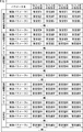
このため、例えば、鮮鋭化処理回路、ノイズリダクション処理回路A乃至N、および欠陥補正処理回路が設けられ、それぞれの画像処理ブロックに対して、制御パラメータ1乃至nであって、かつ、ゲインGain_a乃至Gain_d点に設定値が設定される場合、例えば、図2で示されるような設定値を設定する必要がある。尚、図2における設定値A乃至BLは、設定値の種別を示す例である。
図2においては、鮮鋭化処理回路、ノイズリダクション処理回路A乃至N、および欠陥補正処理回路の、合計(N+2)個の画像処理ブロックのそれぞれに対して、制御パラメータ1乃至Nに対する設定値が設定され、さらに、それぞれの制御パラメータに対して、ゲインGain_a乃至Gain_d点のそれぞれに設定値が設定されている。
したがって、図2の場合、(4×n×(N+2))個の設定値のテーブルを、記憶素子などに記憶しておく必要がある。
そして、処理対象フレームのイメージセンサのGain情報から、図2で示される設定値のテーブルより、近傍の2点のGain値の設定値が読み出され、これを用いた補間処理が実行されて設定値が決定されて、制御対象となる画像処理ブロックに供給され、画像処理ブロックにより処理が実行される。この処理が、複数の画像処理ブロックにより個々に実行される。
尚、制御パラメータの設定値を決定する処理は、撮像された画像を処理しているタイミングで実行されると、処理対象画像の1Frameの途中でパラメータ設定が切り替わり、その切り替わり前後で補正効果が異なり、1Frameの画像の連続性が破綻してしまう恐れがある。そのため、予め補正処理を開始するまでに設定するパラメータを用意しておく必要がある。つまり、毎Frame設定を切り替えていく場合は、最大でも1Frame期間中に設定パラメータを算出する必要があり、記憶素子容量の観点だけでなく、補間計算に必要な処理時間の観点からも、制御対象パラメータ数を増やさない方が望ましい。
<図2のテーブルを用いた場合の設定値供給処理>
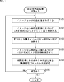
ここで、図3のフローチャートを参照して、図2の設定値のテーブルを用いた場合の具体的な、画像処理ブロックに対して設定値を供給する設定値供給処理について説明する。尚、図3のフローチャートの処理は、鮮鋭化処理回路からなる画像処理ブロックにおける、制御パラメータ1について、図2のテーブルを用いた場合の設定値供給処理について説明するものである。当然のことながら、鮮鋭化処理回路以外の画像処理ブロック、および、制御パラメータ1以外の制御パラメータについては、それぞれの処理に対応したテーブルの値が用いられる。
ここで、図3のフローチャートを参照して、図2の設定値のテーブルを用いた場合の具体的な、画像処理ブロックに対して設定値を供給する設定値供給処理について説明する。尚、図3のフローチャートの処理は、鮮鋭化処理回路からなる画像処理ブロックにおける、制御パラメータ1について、図2のテーブルを用いた場合の設定値供給処理について説明するものである。当然のことながら、鮮鋭化処理回路以外の画像処理ブロック、および、制御パラメータ1以外の制御パラメータについては、それぞれの処理に対応したテーブルの値が用いられる。
ステップS11において、処理対象フレームのイメージセンサのGain値から、テーブル上のGain値のうち、補間処理に使用する近傍の2点のGain値を確定する。例えば、イメージセンサのGain値が、テーブル上のGain_bとGain_cの中間値である場合、補間処理に使用するテーブル上の近傍の2点のGain値は、Gain_bとGain_cとなる。その他の値であれば、それぞれの近傍となる前後の2点のGain値が設定される。
ステップS12において、イメージセンサのGain値の近傍の2点における一方のGain値に対応する設定値が読み出される。すなわち、ここでは、Gain値の近傍の2点における一方のGain値となるGain_bの設定値Bが読み出される。
ステップS13において、イメージセンサのGain値の近傍の2点における他方のGain値に対応する設定値が読み出される。すなわち、ここで、Gainの値の近傍の2点における他方のGain値となるGain_cの設定値Cが読み出される。
ステップS14において、イメージセンサのGain値の近傍の2点のGain値の設定値が用いられて、補間処理が実行される。すなわち、ここでは、イメージセンサGain値が、Gain_bとGain_cの中間値であるので、設定値B,Cの中間値が設定値の補間値として求められる。
ステップS15において、求められた補間値が設定値として出力される。すなわち、ここでは、設定値B,Cの中間値が設定値の補間値として出力される。
ステップS16において、処理の終了が指示されているか否かが判定され、処理の終了が指示されていない場合、処理は、ステップS11に戻り、それ以降の処理が繰り返される。そして、ステップS16において、処理の終了が指示された場合、処理は、終了する。
以上の処理により、イメージセンサのGain値に応じて、設定値が設定されて画像処理ブロックに供給される。
<イメージセンサの温度値に応じた制御パラメータについて>
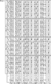
さらに、イメージセンサの温度値によるノイズ量の影響を考慮した場合、例えば、低温[温度_1]、中低温[温度_2]、中高温[温度_3]、高温[温度_4]の4点の温度値について最適な各画像処理ブロックの設定値を記憶素子に保存した場合、図4で示されるような情報量の設定値が記憶される必要がある。すなわち、記憶素子に記憶されるべき、図4の情報量は、図2の情報量が、4点の各温度値に対してそれぞれ必要となるため、図2の情報量の4倍となる。
さらに、イメージセンサの温度値によるノイズ量の影響を考慮した場合、例えば、低温[温度_1]、中低温[温度_2]、中高温[温度_3]、高温[温度_4]の4点の温度値について最適な各画像処理ブロックの設定値を記憶素子に保存した場合、図4で示されるような情報量の設定値が記憶される必要がある。すなわち、記憶素子に記憶されるべき、図4の情報量は、図2の情報量が、4点の各温度値に対してそれぞれ必要となるため、図2の情報量の4倍となる。
イメージセンサの温度を考慮した場合、図4で示される記憶素子に保存されている設定値から、各画像処理ブロックのそれぞれの制御パラメータの設定値が算出されることになる。
<図4のテーブルを用いた場合の設定値供給処理>
ここで、図5のフローチャートを参照して、図4の設定値のテーブルを用いた場合の具体的な設定値供給処理について説明する。尚、図5のフローチャートの処理は、鮮鋭化処理回路における、制御パラメータ1について、図4のテーブルを用いた場合の設定値供給処理を実行する。当然のことながら、鮮鋭化処理回路以外の画像処理、および、制御パラメータ1以外の制御パラメータについては、それぞれの処理に対応したテーブルの値が用いられる。
ここで、図5のフローチャートを参照して、図4の設定値のテーブルを用いた場合の具体的な設定値供給処理について説明する。尚、図5のフローチャートの処理は、鮮鋭化処理回路における、制御パラメータ1について、図4のテーブルを用いた場合の設定値供給処理を実行する。当然のことながら、鮮鋭化処理回路以外の画像処理、および、制御パラメータ1以外の制御パラメータについては、それぞれの処理に対応したテーブルの値が用いられる。
また、ここでは、イメージセンサGain値がGain_b点Gain_c点の中間のGain値であり、イメージセンサの温度値が[温度_1]、[温度_2]の中間の温度値であった場合の鮮鋭化処理回路を構成する画像処理ブロックの制御パラメータ1の算出方法を説明するものとする。
ステップS31において、処理対象フレームのイメージセンサのGain情報から、補間処理に使用する近傍の2点のGain値を確定する。例えば、ここでは、Gain値が、Gain_bとGain_cの中間値であり、その他の値であれば、それぞれの前後の近傍の2点の値が設定される。
ステップS32において、イメージセンサの温度値が取得される。
ステップS33において、処理対象フレームのイメージセンサの温度の測定結果から、補間処理に使用する近傍の2点の温度値を確定する。例えば、ここでは、測定結果から得られるイメージセンサの温度値が温度値[温度_1]、[温度_2]の中間の温度値であるので、補間処理に使用される近傍の温度値は、温度値[温度_1]、[温度_2]となる。尚、イメージセンサの温度値がその他の温度値であれば、イメージセンサの温度値の前後となるテーブル上の温度値が近傍の2点の温度値として設定される。
ステップS34において、一方の温度値におけるイメージセンサのGain値の近傍の2点における一方のGain値の設定値が読み出される。すなわち、ここで、一方の温度値である[温度_1]のイメージセンサのGain値の近傍の2点における一方のGain値となるGain_bの設定値である設定値1Bが読み出される。
ステップS35において、一方の温度値におけるイメージセンサのGain値の近傍の2点における他方のGain値の設定値が読み出される。すなわち、ここで、温度値[温度_1]のGain値の近傍の2点における他方のGain値となるGain_cの設定値である設定値1Cが読み出される。
ステップS36において、一方の温度値におけるイメージセンサのGain値の近傍の2点のGain値の設定値が用いられて、一方の温度値のGain値に基づいた補間処理が実行される。すなわち、ここでは、設定値1B,1Cが用いられて、一方の温度値のイメージセンサのGain値が、Gain_bとGain_cの中間値であるので、設定値1B,1Cの中間値である設定値[1B,1C]が一方の温度値[温度_1]の補間値として求められる。
ステップS37において、他方の温度値におけるイメージセンサのGain値の近傍の2点における一方のGain値の設定値が読み出される。すなわち、ここで、他方の温度値である温度値[温度_2]のイメージセンサのGain値の近傍の2点における一方のGain値となるGain_bの設定値である設定値2Bが読み出される。
ステップS38において、他方の温度値におけるイメージセンサのGain値の近傍の2点における他方のGain値の設定値が読み出される。すなわち、ここで、他方の温度値である温度値[温度_2]のイメージセンサのGain値の近傍の2点における他方のGain値となるGain_cの設定値である設定値2Cが読み出される。
ステップS39において、他方の温度値のイメージセンサのGain値の近傍の2点のGain値の設定値が用いられて、Gain値に基づいた補間処理が実行される。すなわち、ここでは、設定値2B,2Cが用いられて、他方の温度値のイメージセンサのGain値が、Gain_bとGain_cの中間値であるので、設定値2B,2Cの中間値である設定値[2B,2C]が温度値[温度_2]の補間値として求められる。
ステップS40において、一方の温度の補間値となる設定値と、他方の温度の補間値となる設定値とが用いられて、イメージセンサの温度値に基づいた補間処理がなされて、補間結果が制御パラメータ1として求められる。すなわち、ここでは、温度値が温度値[温度_1]、[温度_2]の中間の温度値であるので、[温度_1]の補間値である設定値[1B,1C]と、温度値[温度_2]の補間値である設定値[2B,2C]との中間値が、制御パラメータ1の設定値として求められる。
ステップS41において、求められた補間値が設定値として画像処理ブロックに出力される。すなわち、ここでは、設定値[1B,1C]と、設定値[2B,2C]との中間値が補間値として画像処理ブロックに出力される。
ステップS42において、処理の終了が指示されているか否かが判定され、処理の終了が指示されていない場合、処理は、ステップS31に戻り、それ以降の処理が繰り返される。そして、ステップS42において、処理の終了が指示された場合、処理は、終了する。
以上の処理により、イメージセンサのGain値および温度値に応じて、設定値が設定されて画像処理ブロックに供給される。
すなわち、図4のテーブルを用いた補間処理は、図2のテーブルを用いた補間処理と比較すると、読み込むパラメータ値の量が2倍、補間処理の量が3倍、記憶素子に保存するパラメータ設定情報量が4倍になる。
尚、上述した処理においては、Gain値により補間処理を行った後、温度値による補間処理を行う例について説明してきたが、温度値による補間処理を行った後、Gain値により補間処理を行うようにしてもよい。
いずれにおいても、記憶素子に保存しておく設定値の情報量が増加するだけでなく、各画像処理ブロックに設定する制御パラメータを算出するための、設定値の読み込み量と補間処理量もイメージセンサの温度値を考慮すると増加する。
<本開示の撮像装置の第1の実施の形態>
本開示の撮像装置は、上述した記憶素子に保存しておく設定値の量を抑制しつつ、Gain値に基づいた補正と、温度値に基づいた補正とを実現するものである。ここで、図6を参照して、本開示の撮像装置の第1の実施の形態について説明する。
本開示の撮像装置は、上述した記憶素子に保存しておく設定値の量を抑制しつつ、Gain値に基づいた補正と、温度値に基づいた補正とを実現するものである。ここで、図6を参照して、本開示の撮像装置の第1の実施の形態について説明する。
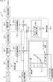
図6の撮像装置1は、イメージセンサ31、画像処理部32、イメージセンサGain値取得部33、イメージセンサ温度値取得部34、および信号処理部35より構成されている。
イメージセンサ31は、CMOS(Complementary Metal Oxide Semiconductor)やCCD(Charge Coupled Device)などから構成されており、光電変換により入射光の光量に応じた電荷を画素単位で発生し、発生した電荷に基づいた画素信号からなる画像を信号処理部35に供給する。
画像処理部32は、イメージセンサ31により撮像された画像に対して所定の処理を施して、信号処理部35に出力する。
イメージセンサGain値取得部33は、イメージセンサ31のGain値を取得してイメージセンサGain値として信号処理部35に供給する。
イメージセンサ温度値取得部34は、イメージセンサ31の温度の測定値であるイメージセンサ温度値を信号処理部35に供給する。
信号処理部35は、イメージセンサGain値取得部33より供給されるイメージセンサGain値と、イメージセンサ温度値取得部34より供給されるイメージセンサ温度値とに基づいて、画像処理部32より供給される画像の画素信号に対して信号処理を施し、図示せぬ後段の装置に出力する。
信号処理部35は、オフセット量算出部51、加算部52、設定値補間部53、および画像処理ブロック54より構成される。
オフセット量算出部51は、例えば、図6の情報P1で示されるような、イメージセンサの温度値に対する、Gain値のオフセット量を、図示せぬ内蔵する記憶素子に記憶しており、イメージセンサ温度値取得部33より供給されるイメージセンサ温度値に基づいて、オフセット量を算出して加算部52に出力する。図6の情報P1は、イメージセンサ温度値に対するイメージセンサGain値のオフセット量ofs_1乃至ofs_4が、離散量からなる4点の温度値[温度_1]乃至[温度_4]に対して記憶されていることが示されている。
4点の各点間における温度値のオフセット量については、オフセット量算出部51が、記憶している4点の温度に対するオフセット量を用いて補間により算出して、加算部52に出力する。
すなわち、オフセット量算出部51は、全ての温度値に対するオフセット量を記憶しているのではなく、例えば、離散的に設定される4点の温度値[温度_1]乃至[温度_4]に対するオフセット量ofs_1乃至ofs_4を記憶しており、4点間の温度値に対するオフセット量は、4点の温度値に対するオフセット量を用いた補間により求める。より詳細には、オフセット量算出部51は、イメージセンサの温度値が、[温度_1]と[温度_2]の中間値である場合、[温度_1]と[温度_2]とのそれぞれのオフセット量ofs_1とofs_2とを用いた補間により、例えば、オフセット量ofs_1とofs_2との中間値をオフセット量とする。
加算部52は、Gain値取得部32より供給されるGain値に対して、オフセット量算出部51より供給されるオフセット量を加算して、設定値補間部53に供給する。
設定値補間部53は、例えば、図6の情報P2で示されるような、Gain値に対する、画像処理ブロック54における画像処理に設定される設定値を、図示せぬ内蔵する記憶素子に記憶しており、加算部52より供給されるイメージセンサGain値に基づいて、設定値を算出して、画像処理ブロック54に供給する。
図6の情報P2は、イメージセンサGain値に対する、画像処理ブロック54に設定される設定値[設定値_A]乃至[設定値_D]が4点のGain値[Gain_1]乃至[Gain_4]に対して記憶されていることが示されている。4点の各点間におけるGain値の設定値については、設定値補間部53が、記憶している4点のGain値[Gain_1]乃至[Gain_4]に対する設定値[設定値_A]乃至[設定値_D]を用いて補間により算出して、画像処理ブロック54に出力する。
すなわち、設定値補間部53は、全てのGain値に対する設定値を記憶しているのではなく、例えば、4点のGain値[Gain_1]乃至[Gain_4]に対する設定値[設定値_A]乃至[設定値_D]を記憶しており、4点間のGain値に対する設定値は、4点のGain値に対する設定値を用いた補間により求める。より詳細には、設定値補間部53は、イメージセンサのGain値が、[Gain_1]と[Gain_2]との中間値である場合、[Gain_1]と[Gain_2]とのそれぞれの設定値[設定値_A]と[設定値_B]とを用いた補間により、例えば、設定値[設定値_A]と[設定値_B]との中間値を設定値とする。
画像処理ブロック54は、イメージセンサ31より供給される画像の各画素の画素信号に対して、設定値補間部53より供給される設定値に基づいた画像処理を施し、図示せぬ後段の構成に出力する。画像処理ブロック54により成される具体的な画像処理は、例えば、鮮鋭化処理、ノイズリダクション処理、および欠陥補正処理である。
尚、オフセット量算出部51により記憶される情報P1、および設定値補間部53に記憶される情報P2については、以上においては、離散的に設定された4点の温度値に対するオフセット量、および、離散的に設定された4点のGain値に対する設定値である例について説明しているが、それ以外の点数であってもよい。ただし、記憶するべき設定値の点数が増えると、情報P1,P2に必要とされる記憶素子の容量を増大させてしまう恐れがあるので、できるだけ必要とされる最小量であることが望ましい。
また、以降においては、イメージセンサGain値取得部32により取得されるGain値は、イメージセンサGain値と称し、イメージセンサ温度値取得部34により取得される温度値は、イメージセンサ温度値と称する。さらに、オフセット量算出部51により記憶される情報P1、および設定値補間部53に記憶される情報P2における設定値が設定されているGain値、および温度値については、単に、Gain値、および温度値と称する。
<図6の撮像装置による設定値供給処理>
次に、図7のフローチャートを参照して、図6の撮像装置1による設定値供給処理について説明する。
次に、図7のフローチャートを参照して、図6の撮像装置1による設定値供給処理について説明する。
ステップS71において、イメージセンサ温度値取得部34は、イメージセンサ31の温度値を測定し、測定結果をイメージセンサ温度値として取得し、オフセット量算出部51に出力する。
ステップS72において、オフセット量算出部51は、取得したイメージセンサ温度値に基づいて、補間に使用する温度値の2点を確定する。すなわち、例えば、取得したイメージセンサ温度値が、温度値[温度_1]と[温度_2]との中間値となる温度値である場合、補間に使用する温度値として、温度値[温度_1]と[温度_2]が確定される。
ステップS73において、オフセット量算出部51は、記憶素子に記憶されている情報P1に基づいて、補間に使用する2点の温度値の一方の温度値に対するオフセット量を読み出す。すなわち、例えば、一方の温度値が温度値[温度_1]である場合、オフセット量算出部51は、温度値[温度_1]に対するオフセット量oft_1を読み出す。
ステップS74において、オフセット量算出部51は、記憶素子に記憶されている情報P1に基づいて、補間に使用する2点の温度値の他方の温度値に対するオフセット量を読み出す。すなわち、例えば、他方の温度値が温度値[温度_2]である場合、オフセット量算出部51は、温度値[温度_2]に対するオフセット量oft_2を読み出す。
ステップS75において、オフセット量算出部51は、読み出した2点の温度値のそれぞれのオフセット量を用いて、取得したイメージセンサ温度値に基づいた補間処理によりオフセット値を確定し、加算部52に供給する。すなわち、例えば、取得したイメージセンサ温度値が温度値[温度_1]と[温度_2]との中間値である場合、オフセット量算出部51は、オフセット量oft_1,oft_2の中間値を補間処理により求め、取得したイメージセンサ温度値に対するオフセット量として確定する。
ステップS76において、加算部52は、補間処理により求められたオフセット量を、Gain値取得部32により取得されたイメージセンサGain値に加算して、設定値補間部53に出力する。
ステップS77において、設定値補間部53は、取得したイメージセンサGain値に基づいて、補間に使用する2点のGain値を確定する。すなわち、例えば、取得したイメージセンサGain値が、Gain値[Gain_1]と[Gain_2]との中間値である場合、補間に使用するGain値として、Gain値[Gain_1]と[Gain_2]が確定される。
ステップS78において、設定値補間部53は、記憶素子に記憶されている情報P2に基づいて、補間に使用する2点のGain値の一方のGain値に対する設定値を読み出す。すなわち、例えば、一方のGain値がGain値[Gain_1]である場合、設定値補間部53は、Gain値[Gain_1]に対する設定値Aを読み出す。
ステップS79において、設定値補間部53は、記憶素子に記憶されている情報P2に基づいて、補間に使用する2点のGain値の他方のGain値に対する設定値を読み出す。すなわち、例えば、他方のGain値がGain値[Gain_2]である場合、設定値補間部53は、Gain値[Gain_2]に対する設定値Bを読み出す。
ステップS80において、設定値補間部53は、読み出した2点のGain値のそれぞれの設定値を用いて、取得したイメージセンサGain値に基づいた補間処理により設定値を確定する。すなわち、例えば、取得したイメージセンサGain値がGain値[Gain_1]と[Gain_2]との中間値である場合、設定値補間部53は、設定値A,Bの中間値を補間処理により求め、取得したGain値に対する設定値として確定する。
ステップS81において、設定値補間部53は、補間処理により求められた設定値を画像処理ブロック54に出力する。この処理により、画像処理ブロック54は、設定値補間部53より供給された設定値に対応する画像処理を画像処理部32より供給される画像信号に施す。
ステップS82において、処理の終了が指示されているか否かが判定され、処理の終了が指示されていない場合、処理は、ステップS71に戻り、それ以降の処理が繰り返される。そして、ステップS82において、処理の終了が指示された場合、処理は、終了する。
以上の処理により、繰り返し出力される設定値により画像処理ブロック54は、画像処理部32より供給される画像に対して、必要な画像処理を施す。
これにより、オフセット量算出部51、および設定値補間部53の記憶素子に記憶される情報量については、例えば、図2で示されるように、制御パラメータ毎にGain値に応じたオフセット量が、例えば、4点分設定される場合、温度値に対しては、オフセット量の情報が4点分増えるのみとなり、図4で示されるような情報量の増大を抑制することが可能となる。また、補間処理に係る処理負荷についても、温度分の処理が1回実施されるのみであるので、処理負荷の増大を抑制することが可能となる。
結果として、イメージセンサの温度値の影響を考慮していない信号処理部を構成した場合に対しても、わずかな記憶領域と補間処理の追加でイメージセンサ温度値を考慮した画像処理を実現することが可能となる。
<本開示の撮像装置の第2の実施の形態>
以上においては、イメージセンサ温度値に対応するオフセット量やイメージセンサGain値に対応する設定値の補間処理については、いずれも線形補間により求める例について説明してきたが、補間処理は、これ以外の処理であってもよく、例えば、n次多項式(nは1以上の整数)により求めるようにしてもよい。
以上においては、イメージセンサ温度値に対応するオフセット量やイメージセンサGain値に対応する設定値の補間処理については、いずれも線形補間により求める例について説明してきたが、補間処理は、これ以外の処理であってもよく、例えば、n次多項式(nは1以上の整数)により求めるようにしてもよい。
図8は、イメージセンサ温度値に対応するオフセット量やイメージセンサGain値に対応する設定値の補間処理をn次多項式により求めるようにした撮像装置の構成例を示している。尚、図8の撮像装置1の構成において、図6の撮像装置1における構成と同一の機能を備えた構成については、同一の符号を付しており、その説明は適宜省略する。
すなわち、図8の撮像装置1において、図6の撮像装置1と異なる点は、オフセット量算出部51、および設定値補間部53に代えて、オフセット量算出部71、および設定値補間部72を設けた点である。
オフセット量算出部71は、基本的な機能は、オフセット量算出部51と略同一であるが、イメージセンサ温度値に対応するオフセット量を線形補間ではなく、例えば、以下の式(1)で示されるようなn次多項式により求める。

ここで、a0,a1,a2,…anは、多項式の係数であり、例えば、最小二乗法により求められる。また、xは、イメージセンサ温度値である。
オフセット量算出部71は、図8の情報P11で示されるように、温度値に対するオフセット量を求めるような、n次多項式の係数を図示せぬ内蔵する記憶素子において記憶しており、係数を用いて、温度値に対応するオフセット値を算出する。
設定値補間部72は、基本的な機能は、設定値補間部53と略同一であるが、Gain値に対応する設定値を線形補間ではなく、例えば、上述した式(1)で示されるようなn次多項式により求める。ただし、設定値補間部72の場合、係数は、オフセット量算出部71とは異なるものとなり、xは、Gain値となる。
<図8の撮像装置による設定値供給処理>
次に、図9のフローチャートを参照して、図8の撮像装置1による設定値供給処理について説明する。
次に、図9のフローチャートを参照して、図8の撮像装置1による設定値供給処理について説明する。
ステップS101において、イメージセンサ温度値取得部34は、イメージセンサ31の温度を測定し、測定結果をイメージセンサ温度値として取得し、オフセット量算出部71に出力する。
ステップS102において、オフセット量算出部71は、取得されたイメージセンサ温度値によりn次多項式を用いた補間処理により、オフセット量を算出して確定する。
ステップS103において、加算部52は、補間処理により求められたオフセット量を、Gain値取得部32により取得されたイメージセンサGain値に加算して、設定値補間部72に出力する。
ステップS104において、設定値補間部72は、イメージセンサGain値によりn次多項式を用いた補間処理により、設定値を算出して確定する。
ステップS105において、設定値補間部72は、補間処理により求められた設定値を画像処理ブロック54に出力する。
ステップS106において、処理の終了が指示されているか否かが判定され、処理の終了が指示されていない場合、処理は、ステップS101に戻り、それ以降の処理が繰り返される。そして、ステップS106において、処理の終了が指示された場合、処理は、終了する。
以上の処理により、繰り返し出力される設定値により画像処理ブロック54は、画像処理部32より供給される画像に対して、必要な画像処理がなされる。
これにより、オフセット量算出部71、および設定値補間部72の記憶素子に記憶される情報量および処理負荷の増大を抑制することが可能となる。
結果として、温度の影響を考慮していない信号処理部を構成した場合に対しても、わずかな記憶領域と補間処理の追加でイメージセンサ温度値に対応した画像処理を実現することが可能となる。
<本開示の撮像装置の第3の実施の形態>
以上においては、信号処理部35が1個である例について説明してきたが、複数に存在し、それぞれのイメージセンサ温度値に対するオフセット量が異なる場合、それぞれ対応する補間処理を実行するようにしてもよい。
以上においては、信号処理部35が1個である例について説明してきたが、複数に存在し、それぞれのイメージセンサ温度値に対するオフセット量が異なる場合、それぞれ対応する補間処理を実行するようにしてもよい。
図10は、信号処理部35が複数に設けられる場合の撮像装置1の構成例を示している。
図10の撮像装置1は、イメージセンサ31、画像処理部32-1乃至32-3、および信号処理部35-1,35-2より構成されている。画像処理部32-1乃至32-3は、画像処理部32と同様の構成であり、信号処理部35-1,35-2は、信号処理部35と同様の構成である。
より詳細には、画像処理部32-1は、イメージセンサ31により撮像された画像に所定の画像処理を施して、信号処理部35-1に供給する。
信号処理部35-1は、画像処理部32-1からの画像に対して、所定の信号処理を実行して、画像処理部32-2に出力する。
画像処理部32-2は、信号処理部35-1により撮像された画像に所定の画像処理を施して、信号処理部35-2に供給する。
信号処理部35-2は、画像処理部32-2からの画像に対して、所定の信号処理を実行して、画像処理部32-3に出力する。
画像処理部32-3は、信号処理部35-2により撮像された画像に所定の画像処理を施して図示せぬ後段の構成に出力する。
ここで、信号処理部35-1,35-2は、それぞれオフセット量算出部51-1,51-2、加算部52-1,52-2、設定値補間部53-1,53-2、および画像処理ブロック54-1,54-2を備えている。オフセット量算出部51-1,51-2、加算部52-1,52-2、設定値補間部53-1,53-2、および画像処理ブロック54-1,54-2は、それぞれオフセット量算出部51、加算部52、設定値補間部53および画像処理ブロック54と基本的な構成は同様である。
しかしながら、画像処理ブロック54-1,54-2は、それぞれ異なる処理、すなわち、例えば、異なる鮮鋭化処理回路、異なるノイズリダクション回路、または、異なる欠陥処理回路として機能し、それぞれの画像処理に対応するように、オフセット量算出部51-1,51-2の図示せぬ記憶素子に記憶されているイメージセンサ温度値に対するオフセット量の情報は、例えば、図10の情報P1-1,P1-2で示されるように、それぞれ異なる情報として記憶されている。
すなわち、情報P1-1においては、温度値[温度_1]に対するオフセット量は、オフセット量ofs_aであり、温度値[温度_2]に対するオフセット量は、オフセット量ofs_bであり、温度値[温度_3]に対するオフセット量は、オフセット量ofs_cであり、温度値[温度_4]に対するオフセット量は、オフセット量ofs_dである。
これに対して、情報P1-2においては、温度値[温度_1]に対するオフセット量は、オフセット量ofs_eであり、温度値[温度_2]に対するオフセット量は、オフセット量ofs_fであり、温度値[温度_3]に対するオフセット量は、オフセット量ofs_gであり、温度値[温度_4]に対するオフセット量は、オフセット量ofs_hである。
図10の撮像装置1においては、信号処理部35-1が、先にイメージセンサ31からの画像に対して信号処理を行い、さらに別の画像処理を経由し、その処理結果を、信号処理部35-2が信号処理する構成となる。このような場合、信号処理部35-2は、信号処理部35-1よりもイメージセンサ温度値によるノイズ変動の影響を受け難いというケースがあり得る。そこで、このような場合、イメージセンサ温度値によるGain値のオフセット量を信号処理部35-1,35-2のそれぞれで保持し、Gain値にそれぞれ異なるオフセット量を加算することで、信号処理部35-1と信号処理部35-2のイメージセンサ温度値に対する影響を独立に制御することが可能となる。
設定値補間部53-1,53-2についても、オフセット量算出部51-1,51-2における情報P1-1,P1-2と同様に、情報P2-1,P2-2が図示せぬ内蔵された記憶素子に記憶されており、それぞれ異なるGain値に対する設定値のテーブルからなる情報が記憶されるようにしてもよい。
尚、信号処理部35-1,35-2のそれぞれの処理については、図7の処理と同様であるので、その説明は省略する。また、オフセット量については、線形補間以外の補間方法でもよく、例えば、図8および図9を参照して説明したn次多項式を用いた補間方法でもよい。
<本開示の撮像装置の第4の実施の形態>
以上においては、信号処理部35が複数に存在し、それぞれの温度値に対するオフセット量が異なる場合、それぞれ異なるオフセット量を用いた補間処理を実行する例について説明してきたが、一方の信号処理部35のオフセット量が、他方の信号処理部35のオフセット量の定数倍であるような場合、他方の信号処理部35は、一方の信号処理部35のオフセット量を定数倍にして、他方の信号処理部35のオフセット量として使用するようにしてもよい。
以上においては、信号処理部35が複数に存在し、それぞれの温度値に対するオフセット量が異なる場合、それぞれ異なるオフセット量を用いた補間処理を実行する例について説明してきたが、一方の信号処理部35のオフセット量が、他方の信号処理部35のオフセット量の定数倍であるような場合、他方の信号処理部35は、一方の信号処理部35のオフセット量を定数倍にして、他方の信号処理部35のオフセット量として使用するようにしてもよい。
図11は、信号処理部35が複数に設けられる場合、他方のオフセット量を一方のオフセット量の定数倍にして使用するようにした撮像装置1の構成例を示している。尚、図11の撮像装置1において、図10の撮像装置1における構成と異なる点は、信号処理部35-2のオフセット量算出部51-2に代えて、乗算部101およびオフセット量変調Gain値102aを記憶したメモリ102が設けられている点である。
図11の撮像装置1における信号処理部35-2の乗算部101は、信号処理部35-1におけるオフセット量算出部51により算出されたオフセット量を取得し、メモリ102に記憶されている、所定の定数であるオフセット量変調Gain値102aを乗算して、信号処理部35-1のオフセット量を定数倍して加算部52-2に出力する。
すなわち、信号処理部35-2のオフセット量が、例えば、信号処理部35-1のオフセット量の50%でよい場合、オフセット量変調Gain値102aを0.5とすることで、信号処理部35-1のオフセット量に0.5を乗じることで、信号処理部35-1のオフセット量の50%のオフセット量を信号処理部35-2のオフセット量として利用することができる。
このような構成により、信号処理部35-2のオフセット量は、信号処理部35-1のオフセット量に対して、所定倍となるオフセット量変調Gain値102aが乗算された値を用いるだけでよくなるので、信号処理部35-2においては、オフセット量算出部51の構成が不要となり、装置構成におけるコストと処理負荷を低減させることが可能となる。
以上の如く、本開示の撮像装置によれば、ノイズ量に応じた処理をする画像処理ブロックの最適な設定値を記憶する量と、その補間演算に係る処理負荷を低減することが可能となる。
すなわち、例えば、イメージセンサGain値に応じて4点の設定値を記憶し、かつ、イメージセンサ温度値に応じて4点の設定値を記憶する場合、4×4=16通りの設定値を記憶する必要がある。また、ノイズ量に応じて最適な設定調整をする必要がある制御パラメータが多数ある場合、16通りの組み合わせをパラメータ数分の組みで記憶しておく必要がある。
しかしながら、本開示の撮像装置においては、4つの温度値に対応したオフセット値を保持して、オフセット量を求め、そのオフセット量をイメージセンサGain値に加算してGain値として用いるようにすることで、イメージセンサGain値とイメージセンサ温度値とのそれぞれに対する補正を掛けることが可能となり、制御パラメータ毎の設定値の情報量を低減すると共に、補間処理に係る処理負荷を低減することが可能となる。
<図11の撮像装置による設定値供給処理>
次に、図12のフローチャートを参照して、図11の撮像装置1による設定値供給処理について説明する。尚、図11の撮像装置1のうち、信号処理部35-1による設定値供給処理については、図7を参照して説明した処理と同様であるので、その説明は省略し、信号処理部35-2による設定値供給処理について説明する。ただし、同時に、信号処理部35-1による設定値供給処理がなされており、信号処理部35-1のオフセット量は求められており、信号処理部35-2に供給されるものとする。また、図12のステップS114乃至S119の処理は、図7のステップS76乃至S82の処理と同様であるので、その説明は省略する。
次に、図12のフローチャートを参照して、図11の撮像装置1による設定値供給処理について説明する。尚、図11の撮像装置1のうち、信号処理部35-1による設定値供給処理については、図7を参照して説明した処理と同様であるので、その説明は省略し、信号処理部35-2による設定値供給処理について説明する。ただし、同時に、信号処理部35-1による設定値供給処理がなされており、信号処理部35-1のオフセット量は求められており、信号処理部35-2に供給されるものとする。また、図12のステップS114乃至S119の処理は、図7のステップS76乃至S82の処理と同様であるので、その説明は省略する。
すなわち、ステップS111において、乗算部101は、信号処理部35-1により求められたオフセット量を取得する。
ステップS112において、乗算部101は、メモリ102に格納されている所定の定数からなるオフセット量変調Gain値102aを読み出し、取得したオフセット量に乗算し、加算部52-2に供給する。
以降の処理により、信号処理部35-2における処理に必要な設定値が求められて、画像処理ブロック54-2に供給されて、処理が実行される。
これにより、複数の信号処理部35が設けられた場合において、全ての信号処理部35に対してオフセット量算出部51を設ける必要がなくなるので、装置コストおよび補間処理負荷、並びに消費電力の低減を実現することが可能となる。
<電子機器への適用例>
上述した撮像装置1は、例えば、デジタルスチルカメラやデジタルビデオカメラなどの撮像装置、撮像機能を備えた携帯電話機、または、撮像機能を備えた他の機器といった各種の電子機器に適用することができる。
上述した撮像装置1は、例えば、デジタルスチルカメラやデジタルビデオカメラなどの撮像装置、撮像機能を備えた携帯電話機、または、撮像機能を備えた他の機器といった各種の電子機器に適用することができる。
図13は、本技術を適用した電子機器としての撮像装置の構成例を示すブロック図である。
図13に示される撮像装置201は、光学系202、シャッタ装置203、固体撮像素子204、駆動回路205、信号処理回路206、モニタ207、およびメモリ208を備えて構成され、静止画像および動画像を撮像可能である。
光学系202は、1枚または複数枚のレンズを有して構成され、被写体からの光(入射光)を固体撮像素子204に導き、固体撮像素子204の受光面に結像させる。
シャッタ装置203は、光学系202および固体撮像素子204の間に配置され、駆動回路205の制御に従って、固体撮像素子204への光照射期間および遮光期間を制御する。
固体撮像素子204は、上述した固体撮像素子を含むパッケージにより構成される。固体撮像素子204は、光学系202およびシャッタ装置203を介して受光面に結像される光に応じて、一定期間、信号電荷を蓄積する。固体撮像素子204に蓄積された信号電荷は、駆動回路205から供給される駆動信号(タイミング信号)に従って転送される。
駆動回路205は、固体撮像素子204の転送動作、および、シャッタ装置203のシャッタ動作を制御する駆動信号を出力して、固体撮像素子204およびシャッタ装置203を駆動する。
信号処理回路206は、固体撮像素子204から出力された信号電荷に対して各種の信号処理を施す。信号処理回路206が信号処理を施すことにより得られた画像(画像データ)は、モニタ207に供給されて表示されたり、メモリ208に供給されて記憶(記録)されたりする。
このように構成されている撮像装置201においても、上述した撮像装置1における信号処理部35を信号処理回路206に適用することにより、設定値を記憶する記憶素子に記憶させる情報量を低減すると共に、信号処理における補間処理に係る処理負荷を低減することが可能となる。結果として、装置コスト、および消費電力の低減を実現することが可能となる。
<撮像素子の使用例>
<撮像素子の使用例>
図14は、上述の撮像装置201を使用する使用例を示す図である。
上述した撮像素子は、例えば、以下のように、可視光や、赤外光、紫外光、X線等の光をセンシングする様々なケースに使用することができる。
・ディジタルカメラや、カメラ機能付きの携帯機器等の、鑑賞の用に供される画像を撮影する装置
・自動停止等の安全運転や、運転者の状態の認識等のために、自動車の前方や後方、周囲、車内等を撮影する車載用センサ、走行車両や道路を監視する監視カメラ、車両間等の測距を行う測距センサ等の、交通の用に供される装置
・ユーザのジェスチャを撮影して、そのジェスチャに従った機器操作を行うために、TVや、冷蔵庫、エアーコンディショナ等の家電に供される装置
・内視鏡や、赤外光の受光による血管撮影を行う装置等の、医療やヘルスケアの用に供される装置
・防犯用途の監視カメラや、人物認証用途のカメラ等の、セキュリティの用に供される装置
・肌を撮影する肌測定器や、頭皮を撮影するマイクロスコープ等の、美容の用に供される装置
・スポーツ用途等向けのアクションカメラやウェアラブルカメラ等の、スポーツの用に供される装置
・畑や作物の状態を監視するためのカメラ等の、農業の用に供される装置
・自動停止等の安全運転や、運転者の状態の認識等のために、自動車の前方や後方、周囲、車内等を撮影する車載用センサ、走行車両や道路を監視する監視カメラ、車両間等の測距を行う測距センサ等の、交通の用に供される装置
・ユーザのジェスチャを撮影して、そのジェスチャに従った機器操作を行うために、TVや、冷蔵庫、エアーコンディショナ等の家電に供される装置
・内視鏡や、赤外光の受光による血管撮影を行う装置等の、医療やヘルスケアの用に供される装置
・防犯用途の監視カメラや、人物認証用途のカメラ等の、セキュリティの用に供される装置
・肌を撮影する肌測定器や、頭皮を撮影するマイクロスコープ等の、美容の用に供される装置
・スポーツ用途等向けのアクションカメラやウェアラブルカメラ等の、スポーツの用に供される装置
・畑や作物の状態を監視するためのカメラ等の、農業の用に供される装置
尚、本開示は、以下のような構成も取ることができる。
<1> 画像を撮像するイメージセンサと、
前記イメージセンサのGain値を取得するGain値取得部と、
前記イメージセンサの温度値を取得する温度値取得部と、
前記温度値に応じてオフセットされた前記Gain値に基づいて、前記イメージセンサにより撮像された画像に信号処理を施す信号処理部と
を含む撮像装置。
<2> 前記信号処理部は、
前記画像に対して所定の画像処理を施す画像処理部と、
前記温度値に基づいて、前記Gain値のオフセット量を算出するオフセット量算出部と、
前記Gain値取得部により取得されたGain値に、前記オフセット量を加算する加算部と、
前記加算部により前記オフセット量が加算されたGain値に基づいて、前記画像処理部における前記所定の画像処理に必要とされる設定値を生成する設定値生成部とを含み、
前記画像処理部は、前記設定値に基づいて、前記画像に対して前記所定の画像処理を施す
<1>に記載の撮像装置。
<3> 前記オフセット量算出部は、離散値となる複数の温度値に対するオフセット量を記憶しており、記憶している複数の温度値を用いた補間処理により、前記温度値取得部により取得された温度値のオフセット量を算出する
<2>に記載の撮像装置。
<4> 前記オフセット量算出部は、離散値となる複数の温度値に対するオフセット量を記憶しており、記憶している複数の温度値のうち、前記温度値取得部により取得された温度値の前後の温度値に対するオフセット量を用いた線形補間によりオフセット量を算出する
<3>に記載の撮像装置。
<5> 前記オフセット量算出部は、前記温度値を変数とするn次多項式を用いた補間によりオフセット量を算出する
<2>に記載の撮像装置。
<6> 前記設定値生成部は、離散値となる複数のGain値に対する設定値を記憶しており、記憶している複数の設定値を用いた補間処理により設定値を生成する
<2>に記載の撮像装置。
<7> 前記設定値生成部は、離散値となる複数のGain値に対する設定値を記憶しており、記憶している複数の設定値のうち、前記Gain値取得部により取得されたGain値の前後のGain値に対する設定値を用いた線形補間により設定値を生成する
<6>に記載の撮像装置。
<8> 前記設定値生成部は、前記Gain値を変数とするn次多項式を用いた補間により設定値を生成する
<2>に記載の撮像装置。
<9> 前記信号処理部が、複数に存在し、前記画像に対して、それぞれ異なる所定の信号処理を行う場合、前記複数の前記信号処理部の前記オフセット量算出部は、前記離散値となる複数の温度値に対する、それぞれ異なるオフセット量を記憶している
<2>に記載の撮像装置。
<10> 前記信号処理部が、前記画像に対して、異なる信号処理を行うものが複数に存在する場合、
前記複数の前記信号処理部のうちの一部は、
前記画像に対して第1の画像処理を施す第1の画像処理部と、
前記温度値に基づいて、前記Gain値の第1のオフセット量を算出する第1のオフセット量算出部と、
前記Gain値取得部により取得されたGain値に、前記第1のオフセット量を加算する第1の加算部と、
前記第1の加算部により前記第1のオフセット量が加算されたGain値に基づいて、前記画像処理部における前記第1の画像処理に必要とされる第1の設定値を生成する第1の設定値生成部とを含み、
前記第1の画像処理部は、前記第1の設定値に基づいて前記画像に対して前記第1の画像処理を施し、
前記複数の前記信号処理部のうちの前記一部と異なる他の一部は、
前記画像に対して第2の画像処理を施す第2の画像処理部と、
前記第1のオフセット量算出部により算出された前記第1のオフセット量に対して、所定の係数を乗じて第2のオフセット量を算出する第2のオフセット量算出部と、
前記Gain値取得部により取得されたGain値に、前記第2のオフセット量を加算する第2の加算部と、
前記第2の加算部により前記第2のオフセット量が加算されたGain値に基づいて、前記第2の画像処理部における前記第2の画像処理に必要とされる第2の設定値を生成する第2の設定値生成部とを含み、
前記第2の画像処理部は、前記第2の設定値に基づいて前記画像に対して前記第2の画像処理を施す
<1>に記載の撮像装置。
<11> 画像を撮像するイメージセンサと、
前記イメージセンサのGain値を取得するGain値取得部と、
前記イメージセンサの温度値を取得する温度値取得部とを含む撮像装置の撮像方法であって、
前記温度値に応じてオフセットされた前記Gain値に基づいて、前記イメージセンサにより撮像された画像に信号処理を施す
ステップを含む撮像方法。
<12> 画像を撮像するイメージセンサと、
前記イメージセンサのGain値を取得するGain値取得部と、
前記イメージセンサの温度値を取得する温度値取得部と、
前記温度値に応じてオフセットされた前記Gain値に基づいて、前記イメージセンサにより撮像された画像に信号処理を施す信号処理部と
を含む電子機器。
<13> イメージセンサにより撮像された画像に対して所定の画像処理を施す画像処理部と、
前記イメージセンサの温度値に基づいて、前記イメージセンサのGain値のオフセット量を算出するオフセット量算出部と、
前記イメージセンサのGain値に、前記オフセット量を加算する加算部と、
前記加算部により前記オフセット量が加算されたGain値に基づいて、前記画像処理部における前記所定の画像処理に必要とされる設定値を生成する設定値生成部とを含み、
前記画像処理部は、前記設定値に基づいて、前記画像に対して前記所定の画像処理を施す
信号処理装置。
<1> 画像を撮像するイメージセンサと、
前記イメージセンサのGain値を取得するGain値取得部と、
前記イメージセンサの温度値を取得する温度値取得部と、
前記温度値に応じてオフセットされた前記Gain値に基づいて、前記イメージセンサにより撮像された画像に信号処理を施す信号処理部と
を含む撮像装置。
<2> 前記信号処理部は、
前記画像に対して所定の画像処理を施す画像処理部と、
前記温度値に基づいて、前記Gain値のオフセット量を算出するオフセット量算出部と、
前記Gain値取得部により取得されたGain値に、前記オフセット量を加算する加算部と、
前記加算部により前記オフセット量が加算されたGain値に基づいて、前記画像処理部における前記所定の画像処理に必要とされる設定値を生成する設定値生成部とを含み、
前記画像処理部は、前記設定値に基づいて、前記画像に対して前記所定の画像処理を施す
<1>に記載の撮像装置。
<3> 前記オフセット量算出部は、離散値となる複数の温度値に対するオフセット量を記憶しており、記憶している複数の温度値を用いた補間処理により、前記温度値取得部により取得された温度値のオフセット量を算出する
<2>に記載の撮像装置。
<4> 前記オフセット量算出部は、離散値となる複数の温度値に対するオフセット量を記憶しており、記憶している複数の温度値のうち、前記温度値取得部により取得された温度値の前後の温度値に対するオフセット量を用いた線形補間によりオフセット量を算出する
<3>に記載の撮像装置。
<5> 前記オフセット量算出部は、前記温度値を変数とするn次多項式を用いた補間によりオフセット量を算出する
<2>に記載の撮像装置。
<6> 前記設定値生成部は、離散値となる複数のGain値に対する設定値を記憶しており、記憶している複数の設定値を用いた補間処理により設定値を生成する
<2>に記載の撮像装置。
<7> 前記設定値生成部は、離散値となる複数のGain値に対する設定値を記憶しており、記憶している複数の設定値のうち、前記Gain値取得部により取得されたGain値の前後のGain値に対する設定値を用いた線形補間により設定値を生成する
<6>に記載の撮像装置。
<8> 前記設定値生成部は、前記Gain値を変数とするn次多項式を用いた補間により設定値を生成する
<2>に記載の撮像装置。
<9> 前記信号処理部が、複数に存在し、前記画像に対して、それぞれ異なる所定の信号処理を行う場合、前記複数の前記信号処理部の前記オフセット量算出部は、前記離散値となる複数の温度値に対する、それぞれ異なるオフセット量を記憶している
<2>に記載の撮像装置。
<10> 前記信号処理部が、前記画像に対して、異なる信号処理を行うものが複数に存在する場合、
前記複数の前記信号処理部のうちの一部は、
前記画像に対して第1の画像処理を施す第1の画像処理部と、
前記温度値に基づいて、前記Gain値の第1のオフセット量を算出する第1のオフセット量算出部と、
前記Gain値取得部により取得されたGain値に、前記第1のオフセット量を加算する第1の加算部と、
前記第1の加算部により前記第1のオフセット量が加算されたGain値に基づいて、前記画像処理部における前記第1の画像処理に必要とされる第1の設定値を生成する第1の設定値生成部とを含み、
前記第1の画像処理部は、前記第1の設定値に基づいて前記画像に対して前記第1の画像処理を施し、
前記複数の前記信号処理部のうちの前記一部と異なる他の一部は、
前記画像に対して第2の画像処理を施す第2の画像処理部と、
前記第1のオフセット量算出部により算出された前記第1のオフセット量に対して、所定の係数を乗じて第2のオフセット量を算出する第2のオフセット量算出部と、
前記Gain値取得部により取得されたGain値に、前記第2のオフセット量を加算する第2の加算部と、
前記第2の加算部により前記第2のオフセット量が加算されたGain値に基づいて、前記第2の画像処理部における前記第2の画像処理に必要とされる第2の設定値を生成する第2の設定値生成部とを含み、
前記第2の画像処理部は、前記第2の設定値に基づいて前記画像に対して前記第2の画像処理を施す
<1>に記載の撮像装置。
<11> 画像を撮像するイメージセンサと、
前記イメージセンサのGain値を取得するGain値取得部と、
前記イメージセンサの温度値を取得する温度値取得部とを含む撮像装置の撮像方法であって、
前記温度値に応じてオフセットされた前記Gain値に基づいて、前記イメージセンサにより撮像された画像に信号処理を施す
ステップを含む撮像方法。
<12> 画像を撮像するイメージセンサと、
前記イメージセンサのGain値を取得するGain値取得部と、
前記イメージセンサの温度値を取得する温度値取得部と、
前記温度値に応じてオフセットされた前記Gain値に基づいて、前記イメージセンサにより撮像された画像に信号処理を施す信号処理部と
を含む電子機器。
<13> イメージセンサにより撮像された画像に対して所定の画像処理を施す画像処理部と、
前記イメージセンサの温度値に基づいて、前記イメージセンサのGain値のオフセット量を算出するオフセット量算出部と、
前記イメージセンサのGain値に、前記オフセット量を加算する加算部と、
前記加算部により前記オフセット量が加算されたGain値に基づいて、前記画像処理部における前記所定の画像処理に必要とされる設定値を生成する設定値生成部とを含み、
前記画像処理部は、前記設定値に基づいて、前記画像に対して前記所定の画像処理を施す
信号処理装置。
1 撮像装置, 31 イメージセンサ, 32,32-1乃至32-3 画像処理部, 33 イメージセンサGain値取得部, 34 イメージセンサ温度値, 35,35-1,35-2 信号処理部, 51,51-,51-2 オフセット量算出部, 52,52-1,52-2 加算部, 53,53-1,53-2 設定値補間部, 54,54-1,54-2 画像処理ブロック, 71 オフセット量算出部, 72 設定値補間部, 101 乗算部, 102 メモリ, 102a オフセット値変調Gain値
Claims (13)
- 画像を撮像するイメージセンサと、
前記イメージセンサのGain値を取得するGain値取得部と、
前記イメージセンサの温度値を取得する温度値取得部と、
前記温度値に応じてオフセットされた前記Gain値に基づいて、前記イメージセンサにより撮像された画像に信号処理を施す信号処理部と
を含む撮像装置。 - 前記信号処理部は、
前記画像に対して所定の画像処理を施す画像処理部と、
前記温度値に基づいて、前記Gain値のオフセット量を算出するオフセット量算出部と、
前記Gain値取得部により取得されたGain値に、前記オフセット量を加算する加算部と、
前記加算部により前記オフセット量が加算されたGain値に基づいて、前記画像処理部における前記所定の画像処理に必要とされる設定値を生成する設定値生成部とを含み、
前記画像処理部は、前記設定値に基づいて、前記画像に対して前記所定の画像処理を施す
請求項1に記載の撮像装置。 - 前記オフセット量算出部は、離散値となる複数の温度値に対するオフセット量を記憶しており、記憶している複数の温度値を用いた補間処理により、前記温度値取得部により取得された温度値のオフセット量を算出する
請求項2に記載の撮像装置。 - 前記オフセット量算出部は、離散値となる複数の温度値に対するオフセット量を記憶しており、記憶している複数の温度値のうち、前記温度値取得部により取得された温度値の前後の温度値に対するオフセット量を用いた線形補間によりオフセット量を算出する
請求項3に記載の撮像装置。 - 前記オフセット量算出部は、前記温度値を変数とするn次多項式を用いた補間によりオフセット量を算出する
請求項2に記載の撮像装置。 - 前記設定値生成部は、離散値となる複数のGain値に対する設定値を記憶しており、記憶している複数の設定値を用いた補間処理により設定値を生成する
請求項2に記載の撮像装置。 - 前記設定値生成部は、離散値となる複数のGain値に対する設定値を記憶しており、記憶している複数の設定値のうち、前記Gain値取得部により取得されたGain値の前後のGain値に対する設定値を用いた線形補間により設定値を生成する
請求項6に記載の撮像装置。 - 前記設定値生成部は、前記Gain値を変数とするn次多項式を用いた補間により設定値を生成する
請求項2に記載の撮像装置。 - 前記信号処理部が、複数に存在し、前記画像に対して、それぞれ異なる所定の信号処理を行う場合、前記複数の前記信号処理部の前記オフセット量算出部は、前記離散値となる複数の温度値に対する、それぞれ異なるオフセット量を記憶している
請求項2に記載の撮像装置。 - 前記信号処理部が、前記画像に対して、異なる信号処理を行うものが複数に存在する場合、
前記複数の前記信号処理部のうちの一部は、
前記画像に対して第1の画像処理を施す第1の画像処理部と、
前記温度値に基づいて、前記Gain値の第1のオフセット量を算出する第1のオフセット量算出部と、
前記Gain値取得部により取得されたGain値に、前記第1のオフセット量を加算する第1の加算部と、
前記第1の加算部により前記第1のオフセット量が加算されたGain値に基づいて、前記画像処理部における前記第1の画像処理に必要とされる第1の設定値を生成する第1の設定値生成部とを含み、
前記第1の画像処理部は、前記第1の設定値に基づいて前記画像に対して前記第1の画像処理を施し、
前記複数の前記信号処理部のうちの前記一部と異なる他の一部は、
前記画像に対して第2の画像処理を施す第2の画像処理部と、
前記第1のオフセット量算出部により算出された前記第1のオフセット量に対して、所定の係数を乗じて第2のオフセット量を算出する第2のオフセット量算出部と、
前記Gain値取得部により取得されたGain値に、前記第2のオフセット量を加算する第2の加算部と、
前記第2の加算部により前記第2のオフセット量が加算されたGain値に基づいて、前記第2の画像処理部における前記第2の画像処理に必要とされる第2の設定値を生成する第2の設定値生成部とを含み、
前記第2の画像処理部は、前記第2の設定値に基づいて前記画像に対して前記第2の画像処理を施す
請求項1に記載の撮像装置。 - 画像を撮像するイメージセンサと、
前記イメージセンサのGain値を取得するGain値取得部と、
前記イメージセンサの温度値を取得する温度値取得部とを含む撮像装置の撮像方法であって、
前記温度値に応じてオフセットされた前記Gain値に基づいて、前記イメージセンサにより撮像された画像に信号処理を施す
ステップを含む撮像方法。 - 画像を撮像するイメージセンサと、
前記イメージセンサのGain値を取得するGain値取得部と、
前記イメージセンサの温度値を取得する温度値取得部と、
前記温度値に応じてオフセットされた前記Gain値に基づいて、前記イメージセンサにより撮像された画像に信号処理を施す信号処理部と
を含む電子機器。 - イメージセンサにより撮像された画像に対して所定の画像処理を施す画像処理部と、
前記イメージセンサの温度値に基づいて、前記イメージセンサのGain値のオフセット量を算出するオフセット量算出部と、
前記イメージセンサのGain値に、前記オフセット量を加算する加算部と、
前記加算部により前記オフセット量が加算されたGain値に基づいて、前記画像処理部における前記所定の画像処理に必要とされる設定値を生成する設定値生成部とを含み、
前記画像処理部は、前記設定値に基づいて、前記画像に対して前記所定の画像処理を施す
信号処理装置。
Priority Applications (2)
| Application Number | Priority Date | Filing Date | Title |
|---|---|---|---|
| US16/463,674 US11134190B2 (en) | 2017-01-12 | 2017-12-28 | Imaging device, imaging method, electronic device, and signal processing device |
| CN201780082171.5A CN110169043B (zh) | 2017-01-12 | 2017-12-28 | 成像装置、成像方法、电子设备和信号处理装置 |
Applications Claiming Priority (2)
| Application Number | Priority Date | Filing Date | Title |
|---|---|---|---|
| JP2017003364A JP2018113614A (ja) | 2017-01-12 | 2017-01-12 | 撮像装置、および撮像方法、電子機器、並びに信号処理装置 |
| JP2017-003364 | 2017-01-12 |
Publications (1)
| Publication Number | Publication Date |
|---|---|
| WO2018131522A1 true WO2018131522A1 (ja) | 2018-07-19 |
Family
ID=62839864
Family Applications (1)
| Application Number | Title | Priority Date | Filing Date |
|---|---|---|---|
| PCT/JP2017/047372 Ceased WO2018131522A1 (ja) | 2017-01-12 | 2017-12-28 | 撮像装置、および撮像方法、電子機器、並びに信号処理装置 |
Country Status (4)
| Country | Link |
|---|---|
| US (1) | US11134190B2 (ja) |
| JP (1) | JP2018113614A (ja) |
| CN (1) | CN110169043B (ja) |
| WO (1) | WO2018131522A1 (ja) |
Families Citing this family (4)
| Publication number | Priority date | Publication date | Assignee | Title |
|---|---|---|---|---|
| CN109639932A (zh) * | 2019-02-28 | 2019-04-16 | 努比亚技术有限公司 | 图像处理方法、移动终端及计算机可读存储介质 |
| CN110896447B (zh) * | 2019-10-09 | 2020-12-01 | 六安荣耀创新智能科技有限公司 | 通信信号内容差异即时检测平台 |
| CN111405176A (zh) * | 2020-03-09 | 2020-07-10 | 浙江大华技术股份有限公司 | 白点噪声处理方法和装置、调节参数函数获取方法和装置 |
| JP7594840B2 (ja) * | 2021-04-23 | 2024-12-05 | 三菱電機モビリティ株式会社 | カメラ制御装置、カメラ制御方法及び撮像装置 |
Citations (2)
| Publication number | Priority date | Publication date | Assignee | Title |
|---|---|---|---|---|
| JP2002077666A (ja) * | 2000-08-24 | 2002-03-15 | Canon Inc | 撮像装置、測距装置、撮像方法、および測距方法 |
| JP2016144095A (ja) * | 2015-02-03 | 2016-08-08 | オリンパス株式会社 | 撮像装置、撮像装置の制御方法 |
Family Cites Families (8)
| Publication number | Priority date | Publication date | Assignee | Title |
|---|---|---|---|---|
| US7602438B2 (en) * | 2004-10-19 | 2009-10-13 | Eastman Kodak Company | Method and apparatus for capturing high quality long exposure images with a digital camera |
| JP4661168B2 (ja) | 2004-11-02 | 2011-03-30 | ソニー株式会社 | 固体撮像素子の信号処理装置及び方法並びに撮像装置 |
| FR2923121B1 (fr) * | 2007-10-26 | 2010-05-14 | Trixell Sas | Procede de traitement d'images issues d'un detecteur photosensible et detecteur photosensible |
| FR2951895B1 (fr) * | 2009-10-22 | 2012-07-13 | Ulis | Procede de correction des images delivrees par un detecteur non regule en temperature, et detecteur mettant en oeuvre un tel procede |
| JP2012029194A (ja) | 2010-07-27 | 2012-02-09 | Nikon Corp | 電子カメラおよび露出制御プログラム |
| SE536839C2 (sv) * | 2012-12-18 | 2014-09-30 | Flir Systems Ab | Förfarande för kalibrering av sensor, datorprogram och datorläsbart medium. |
| CN104639850A (zh) * | 2013-11-11 | 2015-05-20 | 联咏科技股份有限公司 | 图像感测装置及其黑阶控制方法 |
| FR3038194B1 (fr) * | 2015-06-26 | 2017-08-11 | Ulis | Correction de pixels parasites dans un capteur d'image infrarouge |
-
2017
- 2017-01-12 JP JP2017003364A patent/JP2018113614A/ja active Pending
- 2017-12-28 US US16/463,674 patent/US11134190B2/en active Active
- 2017-12-28 WO PCT/JP2017/047372 patent/WO2018131522A1/ja not_active Ceased
- 2017-12-28 CN CN201780082171.5A patent/CN110169043B/zh active Active
Patent Citations (2)
| Publication number | Priority date | Publication date | Assignee | Title |
|---|---|---|---|---|
| JP2002077666A (ja) * | 2000-08-24 | 2002-03-15 | Canon Inc | 撮像装置、測距装置、撮像方法、および測距方法 |
| JP2016144095A (ja) * | 2015-02-03 | 2016-08-08 | オリンパス株式会社 | 撮像装置、撮像装置の制御方法 |
Also Published As
| Publication number | Publication date |
|---|---|
| CN110169043A (zh) | 2019-08-23 |
| JP2018113614A (ja) | 2018-07-19 |
| CN110169043B (zh) | 2021-05-14 |
| US20210120174A1 (en) | 2021-04-22 |
| US11134190B2 (en) | 2021-09-28 |
Similar Documents
| Publication | Publication Date | Title |
|---|---|---|
| KR101594300B1 (ko) | P s f를 추정하기 위한 장치 및 방법 | |
| CN109479100B (zh) | 图像处理装置、图像处理方法和程序 | |
| US20100271501A1 (en) | Image transforming apparatus and method of controlling operation of same | |
| US20150042839A1 (en) | Distance measuring apparatus, imaging apparatus, and distance measuring method | |
| JPWO2014171051A1 (ja) | 距離測定装置、及び、距離測定方法 | |
| JP2009194700A (ja) | 画像処理装置及び画像処理プログラム | |
| WO2018131522A1 (ja) | 撮像装置、および撮像方法、電子機器、並びに信号処理装置 | |
| JP5657184B2 (ja) | 撮像装置及び信号処理方法 | |
| US9892497B2 (en) | Image processing apparatus, imaging apparatus, and image processing method | |
| JP6471222B2 (ja) | 画像処理装置、画像処理方法およびプログラム | |
| KR101653272B1 (ko) | 디지털 촬영 장치, 그 제어 방법, 및 컴퓨터 판독가능 매체 | |
| JP4360318B2 (ja) | デジタルスチルカメラ | |
| JP7561535B2 (ja) | 撮像装置及びその制御方法、プログラム、記憶媒体 | |
| US12192627B2 (en) | Signal processing device, signal processing method, signal processing program, imaging apparatus and lens apparatus | |
| JP6762767B2 (ja) | 撮像素子、撮像装置、および撮像信号処理方法 | |
| US10382710B2 (en) | Image processing apparatus, image capturing apparatus, and non-transitory computer-readable storage medium | |
| JP2007251611A (ja) | 撮像装置 | |
| JP2009302850A (ja) | 固体撮像素子のノイズ除去装置、撮像装置、固体撮像素子のノイズ除去方法 | |
| JP6532411B2 (ja) | 画像処理装置、撮像装置および画像処理プログラム | |
| JP6704611B2 (ja) | 撮影装置及び撮影方法 | |
| KR101617553B1 (ko) | 노이즈 인식 선형 모델을 사용한 최소 촬영 자동 노출 방법 및 장치 | |
| JP6575667B2 (ja) | 露出制御装置及び光学機器 | |
| JP6149615B2 (ja) | 撮像装置 | |
| JP6432642B2 (ja) | 露出制御装置及び光学機器 | |
| KR101675797B1 (ko) | 흔들림 보정 장치 및 이를 포함하는 디지털 촬영장치 |
Legal Events
| Date | Code | Title | Description |
|---|---|---|---|
| 121 | Ep: the epo has been informed by wipo that ep was designated in this application |
Ref document number: 17890914 Country of ref document: EP Kind code of ref document: A1 |
|
| NENP | Non-entry into the national phase |
Ref country code: DE |
|
| 122 | Ep: pct application non-entry in european phase |
Ref document number: 17890914 Country of ref document: EP Kind code of ref document: A1 |