WO2018131305A1 - 内視鏡 - Google Patents
内視鏡 Download PDFInfo
- Publication number
- WO2018131305A1 WO2018131305A1 PCT/JP2017/042825 JP2017042825W WO2018131305A1 WO 2018131305 A1 WO2018131305 A1 WO 2018131305A1 JP 2017042825 W JP2017042825 W JP 2017042825W WO 2018131305 A1 WO2018131305 A1 WO 2018131305A1
- Authority
- WO
- WIPO (PCT)
- Prior art keywords
- brake
- brake mechanism
- wire
- operation wire
- endoscope
- Prior art date
- Legal status (The legal status is an assumption and is not a legal conclusion. Google has not performed a legal analysis and makes no representation as to the accuracy of the status listed.)
- Ceased
Links
Images


Classifications
-
- A—HUMAN NECESSITIES
- A61—MEDICAL OR VETERINARY SCIENCE; HYGIENE
- A61B—DIAGNOSIS; SURGERY; IDENTIFICATION
- A61B1/00—Instruments for performing medical examinations of the interior of cavities or tubes of the body by visual or photographical inspection, e.g. endoscopes; Illuminating arrangements therefor
- A61B1/005—Flexible endoscopes
- A61B1/008—Articulations
-
- A—HUMAN NECESSITIES
- A61—MEDICAL OR VETERINARY SCIENCE; HYGIENE
- A61B—DIAGNOSIS; SURGERY; IDENTIFICATION
- A61B1/00—Instruments for performing medical examinations of the interior of cavities or tubes of the body by visual or photographical inspection, e.g. endoscopes; Illuminating arrangements therefor
- A61B1/00002—Operational features of endoscopes
- A61B1/00004—Operational features of endoscopes characterised by electronic signal processing
- A61B1/00009—Operational features of endoscopes characterised by electronic signal processing of image signals during a use of endoscope
-
- A—HUMAN NECESSITIES
- A61—MEDICAL OR VETERINARY SCIENCE; HYGIENE
- A61B—DIAGNOSIS; SURGERY; IDENTIFICATION
- A61B1/00—Instruments for performing medical examinations of the interior of cavities or tubes of the body by visual or photographical inspection, e.g. endoscopes; Illuminating arrangements therefor
- A61B1/005—Flexible endoscopes
- A61B1/0051—Flexible endoscopes with controlled bending of insertion part
- A61B1/0052—Constructional details of control elements, e.g. handles
-
- A—HUMAN NECESSITIES
- A61—MEDICAL OR VETERINARY SCIENCE; HYGIENE
- A61B—DIAGNOSIS; SURGERY; IDENTIFICATION
- A61B1/00—Instruments for performing medical examinations of the interior of cavities or tubes of the body by visual or photographical inspection, e.g. endoscopes; Illuminating arrangements therefor
- A61B1/005—Flexible endoscopes
- A61B1/0051—Flexible endoscopes with controlled bending of insertion part
- A61B1/0055—Constructional details of insertion parts, e.g. vertebral elements
-
- A—HUMAN NECESSITIES
- A61—MEDICAL OR VETERINARY SCIENCE; HYGIENE
- A61B—DIAGNOSIS; SURGERY; IDENTIFICATION
- A61B1/00—Instruments for performing medical examinations of the interior of cavities or tubes of the body by visual or photographical inspection, e.g. endoscopes; Illuminating arrangements therefor
- A61B1/005—Flexible endoscopes
- A61B1/0051—Flexible endoscopes with controlled bending of insertion part
- A61B1/0057—Constructional details of force transmission elements, e.g. control wires
-
- A—HUMAN NECESSITIES
- A61—MEDICAL OR VETERINARY SCIENCE; HYGIENE
- A61B—DIAGNOSIS; SURGERY; IDENTIFICATION
- A61B1/00—Instruments for performing medical examinations of the interior of cavities or tubes of the body by visual or photographical inspection, e.g. endoscopes; Illuminating arrangements therefor
- A61B1/04—Instruments for performing medical examinations of the interior of cavities or tubes of the body by visual or photographical inspection, e.g. endoscopes; Illuminating arrangements therefor combined with photographic or television appliances
- A61B1/045—Control thereof
-
- A—HUMAN NECESSITIES
- A61—MEDICAL OR VETERINARY SCIENCE; HYGIENE
- A61B—DIAGNOSIS; SURGERY; IDENTIFICATION
- A61B1/00—Instruments for performing medical examinations of the interior of cavities or tubes of the body by visual or photographical inspection, e.g. endoscopes; Illuminating arrangements therefor
- A61B1/06—Instruments for performing medical examinations of the interior of cavities or tubes of the body by visual or photographical inspection, e.g. endoscopes; Illuminating arrangements therefor with illuminating arrangements
- A61B1/0661—Endoscope light sources
- A61B1/0676—Endoscope light sources at distal tip of an endoscope
-
- A—HUMAN NECESSITIES
- A61—MEDICAL OR VETERINARY SCIENCE; HYGIENE
- A61B—DIAGNOSIS; SURGERY; IDENTIFICATION
- A61B8/00—Diagnosis using ultrasonic, sonic or infrasonic waves
- A61B8/12—Diagnosis using ultrasonic, sonic or infrasonic waves in body cavities or body tracts, e.g. by using catheters
-
- G—PHYSICS
- G02—OPTICS
- G02B—OPTICAL ELEMENTS, SYSTEMS OR APPARATUS
- G02B23/00—Telescopes, e.g. binoculars; Periscopes; Instruments for viewing the inside of hollow bodies; Viewfinders; Optical aiming or sighting devices
- G02B23/24—Instruments or systems for viewing the inside of hollow bodies, e.g. fibrescopes
- G02B23/2476—Non-optical details, e.g. housings, mountings, supports
Definitions
- the present invention relates to an endoscope.
- the insertion portion includes a bending tube (angle portion), a flexible tube (soft portion) connected to the proximal end side of the bending tube, the bending tube, and the flexible tube. And an operation wire inserted into the inside of the tube.
- the bending tube includes a plurality of ring-shaped members (angle rings) that are connected to each other along the insertion direction into the subject and can be bent in at least one direction. One end of the operation wire is connected to the distal end side of the insertion portion.
- the operation wire moves in the axial direction to bend the plurality of ring-shaped members in at least one direction.
- the endoscope described in Patent Document 1 includes an operation unit (main body operation unit) connected to the proximal end side of the insertion unit and a lock unit.
- the operation unit is configured to be rotatable in response to a user operation, and the other end of the operation wire is connected. Then, the operation unit moves the operation wire in the axial direction by rotating.
- the lock means is a member that regulates the rotation of the operation unit in response to a user operation. In other words, the bending tube is maintained in a state of being bent by a predetermined angle by rotating the operation portion by a predetermined amount and operating the lock means.
- a technique for allowing a treatment instrument such as a puncture needle to be inserted into the insertion portion (inside of a flexible tube, a bending tube, etc.) into the endoscope and allowing the treatment tool to protrude from the distal end side of the insertion portion Is also known.
- the operation unit is rotated by a predetermined amount and the lock unit is operated to maintain the state where the bending tube is bent by a predetermined angle.
- a puncture needle is inserted into the insertion unit, and the insertion unit is inserted into the insertion unit. Assume that the puncture needle protrudes from the distal end side.
- a force to return the bending tube from the puncture needle to the bending tube is not bent.
- a tension corresponding to the force acts on the operation wire having one end connected to the distal end side of the insertion portion and the other end connected to the operation portion.
- the operation wire may extend in the axial direction according to the tension.
- the operation wire has a length from the operation portion to the distal end side of the insertion portion, and its length dimension is relatively long. For this reason, when the operation wire is stretched, the stretch amount is also relatively large.
- the bending tube cannot maintain the curved state by a predetermined angle and starts to return to the uncurved state.
- the distal end of the insertion portion moves, so doctors and the like cannot puncture the puncture needle at the target position before inserting the puncture needle. There is a problem.
- the present invention has been made in view of the above, and an object of the present invention is to provide an endoscope that can favorably maintain the bending state of the bending tube.
- an endoscope according to the present invention includes a plurality of ring-shaped members that are connected to each other along an insertion direction into a subject and can be bent in at least one direction.
- a plurality of ring-shaped members that are inserted into the bending tube and the flexible tube and move in the axial direction.
- An operation wire that bends in at least one direction and a proximal end side of the flexible tube, and the operation wires are moved in an axial direction to bend the plurality of ring-shaped members in the at least one direction.
- An operation unit that receives one user operation, a brake mechanism that is provided at a proximal end portion of the bending tube and restricts the movement of the operation wire in accordance with applied power, and a second user that operates the brake mechanism Operations that accept operations Characterized in that it comprises a timber.
- the endoscope according to the present invention further includes a brake wire that transmits power corresponding to the second user operation to the operating member to the brake mechanism in the above-described invention, and the brake mechanism includes the brake A brake pad is provided that contacts the operation wire in accordance with power transmitted by the wire and restricts movement of the operation wire.
- the endoscope according to the present invention is the endoscope according to the above-described invention, wherein a brake cable is connected to the brake mechanism and transmits operating power to the brake mechanism in response to the second user operation to the operating member.
- the brake mechanism further includes a first actuator that operates according to electric power transmitted by the brake cable, and abuts on the operation wire according to the operation of the first actuator, and restricts movement of the operation wire. And a brake pad.
- the endoscope according to the present invention is the fluid pressure that is connected to the brake mechanism in the above-described invention and supplies the operating fluid pressure to the brake mechanism in response to the second user operation to the operating member.
- the brake mechanism further includes a second actuator that operates according to a fluid pressure from the fluid pressure supply pipe, and a contact with the operation wire according to the operation of the second actuator, And a brake pad for restricting movement.
- the bending tube includes a plurality of pins that interconnect the plurality of ring-shaped members, and the plurality of ring-shaped members are adjacent to the ring shape.
- the member When the members rotate relative to each other about the pin, the member is curved in the at least one direction, and the brake mechanism is provided on the proximal end side of the pin located closest to the proximal end among the plurality of pins. It is characterized by.
- the endoscope according to the present invention further includes a convex ultrasonic probe that is provided on the distal end side of the bending tube and transmits / receives ultrasonic waves in the above-described invention, and the operation wire is arranged in the axial direction.
- a first operation wire that bends the plurality of ring-shaped members toward the transmission side of ultrasonic waves from the ultrasonic probe by moving; and the brake mechanism regulates movement of the first operation wires It is characterized by doing.
- the endoscope of the present invention there is an effect that the bending state of the bending tube can be favorably maintained.
- FIG. 1 is a diagram schematically illustrating an endoscope system according to the first embodiment.
- FIG. 2 is an enlarged perspective view of the distal end side of the insertion portion.
- FIG. 3 is a cross-sectional view showing the inside of the bending tube.
- FIG. 4A is a cross-sectional view schematically showing a bending operation member.
- FIG. 4B is a cross-sectional view schematically showing the bending operation member.
- FIG. 5 is a diagram schematically illustrating the first rotation braking unit.
- FIG. 6 is a diagram schematically illustrating a connection relationship between the bending operation member and the operation wire.
- FIG. 7A is a diagram schematically illustrating the brake mechanism.
- FIG. 7B is a diagram schematically illustrating the brake mechanism.
- FIG. 7A is a diagram schematically illustrating the brake mechanism.
- FIG. 8 is a diagram schematically illustrating a connection relationship between the bending operation member and the brake wire.
- FIG. 9A is a diagram for explaining the effect of the first embodiment.
- FIG. 9B is a diagram for explaining the effect of the first embodiment.
- FIG. 10 is a diagram schematically illustrating a brake mechanism according to the second embodiment.
- FIG. 11 is a diagram schematically illustrating a brake mechanism according to the third embodiment.
- FIG. 1 is a diagram schematically showing an endoscope system 1 according to the first embodiment.
- the endoscope system 1 is a system that performs ultrasonic diagnosis in a subject such as a person using an ultrasonic endoscope.
- the endoscope system 1 includes an ultrasonic endoscope 2, an ultrasonic observation device 3, an endoscope observation device 4, and a display device 5.
- the ultrasonic endoscope 2 corresponds to the endoscope according to the present invention.
- the ultrasonic endoscope 2 can be partially inserted into a subject, transmits an ultrasonic pulse toward a body wall in the subject, and receives an ultrasonic echo reflected from the subject. It has a function of outputting an echo signal and a function of imaging the inside of the subject and outputting an image signal.
- the detailed configuration of the ultrasonic endoscope 2 will be described later.
- the ultrasonic observation apparatus 3 is electrically connected to the ultrasonic endoscope 2 via the ultrasonic cable 31 (FIG. 1), and outputs a pulse signal to the ultrasonic endoscope 2 via the ultrasonic cable 31. At the same time, an echo signal is input from the ultrasonic endoscope 2. Then, the ultrasonic observation device 3 performs a predetermined process on the echo signal to generate an ultrasonic image.
- An endoscope connector 9 (FIG. 1) described later of the ultrasonic endoscope 2 is detachably connected to the endoscope observation apparatus 4. As shown in FIG. 1, the endoscope observation apparatus 4 includes a video processor 41 and a light source device 42.
- the video processor 41 inputs an image signal from the ultrasonic endoscope 2 via the endoscope connector 9. Then, the video processor 41 performs a predetermined process on the image signal to generate an endoscopic image.
- the light source device 42 supplies illumination light for illuminating the inside of the subject to the ultrasonic endoscope 2 via the endoscope connector 9.
- the display device 5 is configured using liquid crystal or organic EL (Electro Luminescence), and an ultrasonic image generated by the ultrasonic observation device 3, an endoscope image generated by the endoscope observation device 4, and the like. Is displayed.
- the ultrasonic endoscope 2 includes an insertion portion 6, an operation portion 7, a universal cord 8, and an endoscope connector 9.
- the “tip side” described below means the tip side of the insertion portion 6 (tip side in the direction of insertion into the subject).
- the “proximal end side” described below means a side away from the distal end of the insertion portion 6.
- the insertion part 6 is a part inserted into the subject. As shown in FIG.
- the insertion portion 6 includes an ultrasonic probe 61 provided on the distal end side, a rigid member 62 connected to the proximal end side of the ultrasonic probe 61, and a rigid member 62.
- a bending tube 63 that is connected to the proximal end side and can be bent is provided, and a flexible tube 64 that is connected to the proximal end side of the bending tube 63 and has flexibility.
- a light guide (not shown) for transmitting illumination light supplied from the light source device 42 is provided inside the insertion portion 6, the operation portion 7, the universal cord 8, and the endoscope connector 9, and the above-described pulse signal.
- transducer cable for transmitting an echo signal
- signal cable for transmitting the above-described image signal
- the operation unit 7 is a portion that is connected to the proximal end side of the insertion unit 6 and receives various operations from a doctor or the like. As shown in FIG. 1, the operation unit 7 includes a bending operation member 7 a for bending the bending tube 63 and a plurality of operation members 7 b for performing various operations. The detailed configuration of the bending operation member 7a will be described later.
- a treatment instrument is inserted into the operation section 7 to communicate with a treatment instrument tube (not shown) disposed in the insertion section 6 and a treatment instrument (for example, a puncture needle) is inserted into the treatment instrument tube.
- a mouth 7c is provided.
- the universal cord 8 extends from the operation unit 7, and the above-described light guide, vibrator cable, signal cable, and the like are disposed therein.
- the endoscope connector 9 is provided at the end of the universal cord 8.
- the endoscope connector 9 is connected to the video processor 41 and the light source device 42 by being inserted into the endoscope observation device 4 while being connected to the ultrasonic cable 31.
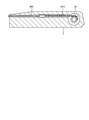
- FIG. 2 is an enlarged perspective view of the distal end side of the insertion portion 6.
- the ultrasonic probe 61 is a convex ultrasonic probe, and is a vibration in which a plurality of ultrasonic transducers are regularly arranged so as to form a convex arc. It has a child part 611.
- the ultrasonic transducer has an acoustic lens, a piezoelectric element, and a matching layer, and acquires an ultrasonic echo that contributes to an internal ultrasonic tomographic image rather than a body wall in the subject.
- the ultrasonic probe 61 converts the pulse signal input from the ultrasonic observation apparatus 3 via the ultrasonic cable 31 and the above-described transducer cable into an ultrasonic pulse and transmits it to the subject. Further, the ultrasonic probe 61 converts an ultrasonic echo reflected in the subject into an electrical echo signal, and outputs it to the ultrasonic observation apparatus 3 via the transducer cable and the ultrasonic cable 31 described above. To do.
- the rigid member 62 has a mounting hole 621, a treatment instrument channel 622, an illumination hole 623, and an imaging hole 624.
- the attachment hole 621 is a hole to which the ultrasonic probe 61 is attached.
- the treatment instrument channel 622 is a hole through which various treatment instruments inserted through the treatment instrument tube described above via the treatment instrument insertion port 7c are projected.
- the illumination hole 623 is provided with one end of the light guide described above and irradiates the subject with illumination light transmitted through the light guide.
- an objective optical system (not shown) that collects light (subject image) that is irradiated into the subject and reflected within the subject, and is condensed by the objective optical system.
- An image pickup device (not shown) for picking up the subject image is provided. And the image signal imaged with the said image pick-up element is transmitted to the endoscope observation apparatus 4 (video processor 41) via the signal cable mentioned above.
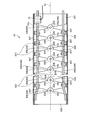
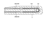
- FIG. 3 is a cross-sectional view showing the inside of the bending tube 63.
- FIG. 3 is a cross-sectional view of the bending tube 63 taken along a plane passing through the central axis Ax of the bending tube 63.
- the bending tube 63 includes a proximal end base 631, a distal end base 632, and a plurality of ring-shaped members 633.
- the outer periphery of the bending tube 63 is covered with a shield member 63a (FIG. 3).
- the outer periphery of the shield member 63a is covered with a covering member made of a flexible material such as rubber.
- the shield member 63a is a shield member such as a metal mesh for the purpose of protecting the above-described covering member, measures against EMC, measures against noise, and the like.
- the shielding member 63a is not shown for convenience of explanation.
- the proximal end base 631 has a cylindrical shape, and the proximal end side (the right side in FIG. 3) is connected to the flexible tube 64.
- the base end base 631 corresponds to the “base end portion of the bending tube” according to the present invention.
- the distal end base 632 has a cylindrical shape, and the distal end side (left side in FIG. 3) is connected to the rigid member 62.
- the plurality of ring-shaped members 633 have the same shape. For this reason, only the shape of one ring-shaped member 633 will be described below. As shown in FIG. 2 or 3, the ring-shaped member 633 includes a cylindrical base 634, two first overhangs 635, two second overhangs 636 (FIG. 3), and two wires.
- the insertion part 637 (FIG. 3) is provided.
- the two first projecting portions 635 are portions projecting toward the distal end side from positions that are rotationally symmetric by 180 ° with respect to the central axis Ax at the end portion on the distal end side of the base body 634.
- the two first overhang portions 635 penetrate the front and back (penetrate in a direction perpendicular to the central axis Ax), and the first pin insertion hole 638 (through which the pin PN (FIGS. 2 and 3) is inserted is inserted. 3) are formed.
- the two second projecting portions 636 are portions that project from the position facing the two first projecting portions 635 to the proximal end side at the proximal end side of the base 634.
- projection part 636 is formed with the 2nd pin insertion hole 639 (FIG. 3) which penetrates the front and back and the pin PN is penetrated similarly to the 1st overhang
- Two ring-shaped members 633 out of the plurality of ring-shaped members 633 include first projecting portions 635 of one ring-shaped member 633 and second projecting portions 636 of the other ring-shaped member 633.
- the pins PN are overlapped with each other and inserted into the first and second pin insertion holes 638 and 639 to be connected to each other. That is, the plurality of ring-shaped members 633 are connected to each other along the insertion direction into the subject by the connection structure described above. Further, the bending tube 63 bends in two directions as the adjacent ring-shaped members 633 rotate around the pin PN.
- the plurality of ring-shaped members 633 include an ultrasonic pulse transmission side from the ultrasonic probe 61 (upper side in FIGS. 2 and 3, hereinafter referred to as an upward direction), and the upper side It is configured to be able to bend in two directions: a downward direction opposite to the direction (downward in FIGS. 2 and 3).
- the ring-shaped member 633 positioned at the proximal end is rotatably coupled to the distal end side of the proximal end base 631 via the pin PN.
- the ring-shaped member 633 located at the distal end is rotatably connected to the proximal end side of the distal end base 632 via a pin PN.
- the two wire insertion portions 637 are portions through which the two operation wires AW are inserted. As shown in FIG. 3, the two wire insertion portions 637 are located on the inner surface of the base 634 at positions where the first and second projecting portions 635 and 636 are rotated by 90 ° with respect to the central axis Ax. Each is provided. As shown in FIG. 3, the two operation wires AW are moved in the axial direction to cause the bending tube 63 to bend upward, and moved in the axial direction to lower the bending tube 63. The second operation wire AW2 is bent in the direction. One end of each of the first and second operation wires AW1 and AW2 is fixed to the inner surface of the distal end base 632 by brazing or the like (FIG. 3), and the bending tube 63 and the flexible tube are connected via the wire insertion portions 637. The other end side is routed to the operation unit 7.
- a brake mechanism 10 that restricts the movement of the first operation wire AW1 according to the applied power is provided on the inner surface of the base end base 631.
- the brake mechanism 10 is located on the inner surface of the base end base 631 on the base end side of the pin PNE (FIGS. 2 and 3) located on the most base end side among the plurality of pins PN.
- the proximal end base 631 is provided on the distal end side. The detailed structure of the brake mechanism 10 will be described later.
- FIG. 4A and 4B are cross-sectional views schematically showing the bending operation member 7a.
- the bending operation member 7a accepts a first user operation for moving the first and second operation wires AW1 and AW2 in the axial direction to bend the bending tube 63 upward or downward, and activates the brake mechanism 10.
- a second user operation hereinafter referred to as a brake operation operation
- a brake release operation for canceling the operation are received.
- the bending operation member 7 a includes first and second support shafts 71 and 72, a bending knob 73, and an operating member 74.
- the first support shaft 71 has a cylindrical shape extending in the vertical direction in FIG. 4A or FIG. 4B, and is fixed inside the operation unit 7.
- the second support shaft 72 has a cylindrical shape into which the first support shaft 71 is inserted, and the inside of the operation unit 7 is coaxial with the first support shaft 71. It is fixed to.
- the bending knob 73 is provided to be rotatable about the first support shaft 71 with respect to the first support shaft 71 and receives a first user operation (rotation operation about the first support shaft 71). is there.
- the bending knob 73 includes a knob body 731, a cylindrical portion 732, and a first sprocket 733.
- the knob main body 731 has a disk shape and is a part operated by a doctor or the like with a hand or a finger.
- a concave portion 734 that is recessed upward is formed at the center of the lower surface in FIG. 4A or 4B.
- the cylindrical portion 732 has a cylindrical shape that extends downward from the center position at the bottom of the recess 734 (the center position of the knob main body 731) in FIG. 4A or 4B, and includes first and second support shafts 71 and 72. It is inserted between.
- the bending knob 73 rotates about the first support shaft 71 while the cylindrical portion 732 is in sliding contact with the outer surface of the first support shaft 71 and the inner surface of the second support shaft 72.
- the first sprocket 733 is fixed to the lower end of the cylindrical portion 732 in FIG. 4A or 4B in a posture in which the central axis thereof matches the central axis of the cylindrical portion 732, and interlocks with the rotation of the bending knob 73.
- the operation member 74 is a part that receives a brake operation operation and a brake release operation. As shown in FIG. 4A or FIG. 4B, the operation member 74 includes a curved fixing lever 75, first to third rotation braking portions 76 to 78, and a second sprocket 79.
- the curved fixing lever 75 is a lever that is located on the lower side in FIG. 4A or 4B with respect to the knob body 731 and extends in a direction away from the first and second support shafts 71 and 72. This is the part that is operated by hand or finger.
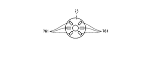
- FIG. 5 is a diagram schematically showing the first rotation braking unit 76.
- FIG. 5 is a view of the first rotation braking unit 76 viewed from above in FIG. 4A or 4B.
- the first rotation braking portion 76 has a substantially cylindrical shape into which the first and second support shafts 71 and 72 and the cylindrical portion 732 are inserted. Further, one end of the bending fixing lever 75 is fixed to the first rotation braking unit 76. And the 1st rotation braking part 76 rotates with the curve fixed lever 75 centering on the 2nd spindle 72 according to brake operation operation and brake release operation.
- a plurality of (six in the first embodiment FIG. 5 is a view of the first rotation braking unit 76 viewed from above in FIG. 4A or 4B.
- the first rotation braking portion 76 has a substantially cylindrical shape into which the first and second support shafts 71 and 72 and the cylindrical portion 732 are inserted. Further, one end of the bending fixing lever 75 is fixed to the first rotation braking unit
- Convex portion 761 is provided.
- the second sprocket 79 is fixed to the lower end in FIG. 4A or FIG. 4B of the first rotation braking unit 76 in a posture in which the center axis thereof matches the center axis of the first rotation braking unit 76, and the first rotation braking unit 76 This is interlocked with the rotation of 76 (curvature fixing lever 75).
- the second rotation braking portion 77 is formed in a disc shape, and has a through hole 771 through which the first and second support shafts 71 and 72 and the cylindrical portion 732 are inserted at the center position.
- the second rotation braking unit 77 is positioned on the upper side in FIG. 4A or 4B of the first rotation braking unit 76 and is positioned in the recess 734. Further, the second rotation braking portion 77 is vertically moved in FIG. 4A or 4B in a state where movement in the rotation direction around the second support shaft 72 is restricted with respect to the second support shaft 72. It is only mounted movable. In the second rotation braking portion 77, the lower surface in FIG.
- the third rotation braking portion 78 is formed in a disk shape and has a through hole 781 through which the first support shaft 71 and the cylindrical portion 732 are inserted at the center position.
- the third rotation braking unit 78 is fixed to the bottom of the recess 734.
- FIG. 6 is a diagram schematically showing a connection relationship between the bending operation member 7a and the operation wire AW.
- the other end side of the first operation wire AW ⁇ b> 1 is routed to the inside of the operation unit 7.
- the other end of the first operation wire AW1 is fixed to one end of the first chain CH1 wound around the first sprocket 733.
- the second operation wire AW2 is also routed to the operation portion 7 at the other end side and fixed to the other end of the first chain CH1.
- the first sprocket 733 rotates (rotates clockwise in FIG.
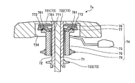
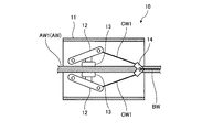
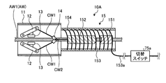
- the brake mechanism 10 includes a container 11, a pair of rotating bars 12, a pair of brake pads 13, a pair of first connection wires CW1, and a wire connecting portion 14. .
- the container 11 has a cylindrical shape, and the first operation wire AW1 is inserted therethrough, and the pair of rotating bars 12, the pair of brake pads 13, the pair of first connection wires CW1, and the wire connecting portion 14. Is the part housed inside.
- the container 11 is fixed to the inner surface of the base end base 631 in a posture in which the central axis is along the central axis Ax.
- the pair of rotating bars 12 has one end positioned on the base end side (the right side in FIG. 7A or FIG. 7B) with the first operation wire AW1 sandwiched therebetween.
- Each other end located on the tip side (left side in FIG. 7A or FIG. 7B) is pivotally supported on the inner surface of the container 11 so as to be close to and separated from the AW1.
- the pair of brake pads 13 are attached to mutually opposing surfaces of the pair of rotating bars 12, and the first operation wire AW1 is moved by sandwiching the first operation wire AW1 (abutting on the first operation wire AW1). regulate.
- each of the pair of first connection wires CW ⁇ b> 1 is connected to each end of the pair of rotating bars 12, and each other end is connected to the wire connecting portion 14.
- the wire connecting portion 14 is located on the proximal end side with respect to the pair of rotation bars 12 and is attached to the first operation wire AW1 so as to be movable in the axial direction thereof. (FIG. 7A, FIG. 7B).
- One end of the brake wire BW is connected to the wire connecting portion 14, is inserted into the bending tube 63 and the flexible tube 64, and the other end is routed to the operation portion 7.
- FIG. 8 is a diagram schematically showing a connection relationship between the bending operation member 7a and the brake wire BW.
- the other end side of the brake wire BW is routed to the inside of the operation unit 7.
- the other end of the brake wire BW is fixed to the end of the second chain CH2 wound around the second sprocket 79. That is, when the second sprocket 79 rotates (rotates clockwise in FIG.
- a pair of rotation bar 12 will be in the state which can rotate in the direction which each end separates from each other. Then, the first operation wire AW1 is released from the pair of brake pads 13 and is allowed to move in the axial direction (FIG. 7A).
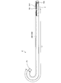
- FIG. 9A and 9B are diagrams for explaining the effect of the first embodiment.
- FIG. 9A schematically shows a conventional insertion portion 6 ′ and operation portion 7 in which the brake mechanism 10 is not provided.
- FIG. 9B schematically shows the insertion portion 6 and the operation portion 7 according to Embodiment 1 in which the brake mechanism 10 is provided.
- the position P1 indicates the position of one end fixed to the distal end base 632 in the first operation wire AW1.
- the position P2 indicates the position of the other end fixed to the first chain CH1 in the first operation wire AW1.
- a position P3 indicates a position fixed by the brake mechanism 10 in the first operation wire AW1.
- the insertion portion 6 ′ (bending tube 63) is bent upward by a predetermined angle by a first user operation on the operation portion 7. Moreover, the rotation of the bending knob 73 is restricted by the brake operation operation to the operating member 74, and the bending state of the insertion portion 6 'is maintained. Further, the puncture needle is inserted into the insertion portion 6 ′ through the treatment instrument insertion port 7 c, and the puncture needle protrudes from the treatment instrument channel 622 to the outside.
- the insertion portion 6 ′ is returned from the puncture needle to the insertion portion 6 ′ to a state in which the insertion portion 6 ′ is not curved.
- the tension acts on the first operation wire AW1 over the substantially entire length L1 (FIG. 9A) from the position P1 to the position P2.
- the extension amount of the first operation wire AW1 corresponding to the tension is also relatively large. For this reason, according to the amount of extension of the first operation wire AW1, the insertion portion 6 ′ cannot maintain the curved state (FIG. 9A) by a predetermined angle, and starts to return to the uncurved state.
- the brake mechanism 10 is provided on the proximal end base 631 of the bending tube 63.
- the brake mechanism 10 is operated, so that the first operation wire AW1 is fixed at the position P3 (FIG. 9B). . That is, in the first embodiment, as in the case described above, when the puncture needle is inserted into the insertion portion 6 while the insertion portion 6 is bent upward by a predetermined angle, the first operation wire Tension acts on AW1 only in a short length L2 from position P1 to position P3 according to the force from the puncture needle.
- the extension amount of the first operation wire AW1 corresponding to the tension is also relatively small. Therefore, the curved state of the insertion portion 6 (the state curved by a predetermined angle (FIG. 9B)) can be favorably maintained. That is, since the position of the distal end of the insertion portion 6 can be maintained, a doctor or the like can puncture the puncture needle at the target position before inserting the puncture needle. In addition, since the tension acts only on the portion from the position P1 to the position P3 (substantially the entire bending tube 63) according to the force from the puncture needle, the flexible tube 64 contracts in the axial direction according to the tension. There is no. That is, when the flexible tube 64 is contracted, the length of the first operation wire AW1 does not become relatively long, and the bending state of the insertion portion 6 can be favorably maintained.
- the brake pad 13 is employed for the brake mechanism 10. For this reason, the movement of the first operation wire AW1 can be restricted with a simple structure.
- the brake mechanism 10 is arranged on the proximal end side of the pin PNE located closest to the proximal end among the plurality of pins PN on the inner surface of the proximal end base 631. Therefore, it is provided on the distal end side of the base end base 631. That is, the brake mechanism 10 is disposed at the most appropriate position with respect to the position where the force from the puncture needle inserted through the insertion portion 6 is received. For this reason, the effect that the bending state of the insertion part 6 mentioned above can be favorably maintained can be suitably realized.
- FIG. 10 is a diagram schematically showing a brake mechanism 10A according to the second embodiment.
- an actuator 15 is added to the brake mechanism 10 described in the first embodiment.
- the brake wire BW is omitted.
- the actuator 15 is located on the proximal end side (right side in FIG. 10) with respect to the wire connecting portion 14 and is fixed to the container 11.
- the actuator 15 corresponds to a first actuator according to the present invention.
- the actuator 15 includes a fixed iron core 151, a movable iron core 152 positioned on the distal end side (left side in FIG. 10) with respect to the fixed iron core 151, and the fixed iron core 151.
- the coil 153 is wound around the movable iron core 152, and the electromagnetic actuator includes a case 154 that accommodates the members 151 to 153 and is fixed to the housing 11.
- the movable iron core 152 and the wire connecting portion 14 are connected by a second connection wire CW2.
- one end of a brake cable 153a is connected to the coil 153.
- the brake cable 153 a is inserted into the bending tube 63, the flexible tube 64, the operation unit 7, and the universal cord 8, and is routed to the inside of the endoscope connector 9.
- the brake cable 153 a transmits operating power from the endoscope observation apparatus 4 to the actuator 15 when the endoscope connector 9 is inserted into the endoscope observation apparatus 4.
- the brake cable 153 a is provided with a changeover switch 75 a that switches between an allowable state that allows transmission of power for operation to the actuator 15 and a cutoff state that blocks the transmission. .
- the changeover switch 75 a is provided in the operation unit 7. Then, the changeover switch 75a switches from the cut-off state to the permissible state by contacting the curve fixing lever 75 according to the brake operation operation to the curve fixing lever 75.
- the movable iron core 152 is attracted to the fixed iron core 151 and moves the wire connecting portion 14 to the proximal end side. Thereby, a pair of rotation bar 12 rotates in the direction where each end adjoins mutually. And 1st operation wire AW1 is clamped by a pair of brake pad 13, and the movement of the axial direction is controlled.
- the changeover switch 75a switches from the permissible state to the cut-off state when the bend fixing lever 75 is separated in accordance with the brake release operation to the bend fixing lever 75. Then, the supply of power for operation to the coil 153 is cut off, so that the movable iron core 152 is released from the fixed iron core 151 and is movable to the tip side. That is, the wire connecting portion 14 is movable to the distal end side. Moreover, a pair of rotation bar 12 will be in the state which can rotate in the direction which each end separates from each other. The first operation wire AW1 is released from the pair of brake pads 13 and is allowed to move in the axial direction (FIG. 10).
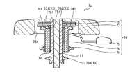
- FIG. 11 is a diagram schematically illustrating a brake mechanism 10B according to the third embodiment.
- an actuator 15B is employed instead of the actuator 15 with respect to the brake mechanism 10A described in the second embodiment.
- the pair of rotating bars 12 are arranged so that the other ends pivotally supported by the container 11 are positioned on the base end side (right side in FIG. 11). It is installed.
- the wire connecting portion 14 is disposed so as to be positioned on the distal end side (left side in FIG. 11) with respect to the pair of rotating bars 12. That is, the pair of rotating bars 12 rotate in a direction in which each one end approaches each other as the wire connecting portion 14 moves to the distal end side.
- the actuator 15 ⁇ / b> B is positioned on the distal end side with respect to the wire connecting portion 14 and is fixed to the container 11.
- the actuator 15B corresponds to a second actuator according to the present invention.
- the actuator 15 ⁇ / b> B is provided in a cylinder 155 fixed to the container 11 and the fluid pressure provided in the cylinder 155 and supplied to the inside of the cylinder 155. Accordingly, it is composed of a fluid pressure actuator (hydraulic actuator, pneumatic actuator or the like) provided with a piston 156 that moves to the tip side accordingly.
- the piston 156 and the wire connecting portion 14 are connected by a third connection wire CW3.
- a fluid pressure supply pipe 155b is connected to the cylinder 155 so as to communicate with the inside thereof.
- the fluid pressure supply pipe 155 b is inserted into the bending pipe 63, the flexible pipe 64, the operation unit 7, and the universal cord 8, and is led to the inside of the endoscope connector 9.
- the fluid pressure supply pipe 155b is connected to a fluid pressure pump (such as a hydraulic pump or a pneumatic pump) (not shown) outside the endoscope connector 9, and the fluid pressure (hydraulic pressure) is applied from the fluid pressure pump to the actuator 15B. Or air pressure).
- a fluid pressure pump such as a hydraulic pump or a pneumatic pump
- a state switching valve 75b that switches between a permissible state in which the supply of the operating fluid pressure to the actuator 15B is allowed and a shut-off state in which the supply is shut off. Is provided.
- the state switching valve 75 b is provided in the operation unit 7. Then, the state switching valve 75b switches from the cut-off state to the permissible state by contacting the curved fixed lever 75 in response to a brake operation operation on the curved fixed lever 75. Then, when fluid pressure is supplied to the cylinder 155, the piston 156 moves to the distal end side and moves the wire connecting portion 14 to the distal end side. Thereby, a pair of rotation bar 12 rotates in the direction where each end adjoins mutually. And 1st operation wire AW1 is clamped by a pair of brake pad 13, and the movement of the axial direction is controlled.
- the state switching valve 75b switches from the allowable state to the cut-off state when the bending fixing lever 75 is separated in accordance with the brake releasing operation to the bending fixing lever 75. Then, when the supply of fluid pressure to the cylinder 155 is interrupted, the piston 156 becomes movable to the base end side. That is, the wire connecting portion 14 is movable to the proximal end side. Moreover, a pair of rotation bar 12 will be in the state which can rotate in the direction which each end separates from each other. The first operation wire AW1 is released from the pair of brake pads 13 and is allowed to move in the axial direction (FIG. 11).
- the endoscope system 1 has both the function of generating an ultrasonic image and the function of generating an endoscopic image. A configuration having only one function may be used.
- the endoscope system 1 is used not only in the medical field but also in the industrial field, and may be an endoscope system that observes the inside of a subject such as a mechanical structure.
- the operation wire AW is composed of two wires: the first operation wire AW1 that bends the bending tube 63 upward and the second operation wire AW2 that bends the bending tube 63 downward.
- any number may be provided as long as it is one or more.
- a third operation wire for bending the bending tube 63 in the left direction and a fourth operation wire for bending the bending tube 63 in the right direction may be added, and may be configured with four or more wires.
- the brake mechanisms 10, 10A, and 10B are provided only for the first operation wire AW1, but the present invention is not limited to this.
- a brake mechanism that restricts the movement of the second operation wire AW2 may be provided.
- a brake mechanism that restricts the movement of the third and fourth operation wires may be provided.
- the brake mechanism provided for the second to fourth operation wires is also preferably provided at the proximal end portion of the bending tube 63.
- the brake mechanisms 10, 10A, and 10B are provided on the inner surface of the base end base 631. However, if the brake mechanisms are provided on the base end side in the bending tube 63, the other mechanisms are provided. You may provide in a position.
- one end of each of the first and second operation wires AW1 and AW2 is fixed to the inner surface of the tip base 632.
- the present invention is not limited to this, and each end is fixed to the rigid member 62. It doesn't matter.
- the brake mechanism 10, 10A, 10B is not limited to the structure described in the first to third embodiments, and other structures may be employed.
- the operation member according to the present invention employs a configuration that accepts a lever operation by a doctor or the like, but is not limited thereto, and adopts a configuration that accepts a switch operation by a doctor or the like. It doesn't matter.
Landscapes
- Health & Medical Sciences (AREA)
- Life Sciences & Earth Sciences (AREA)
- Surgery (AREA)
- Physics & Mathematics (AREA)
- Engineering & Computer Science (AREA)
- Biomedical Technology (AREA)
- Medical Informatics (AREA)
- Nuclear Medicine, Radiotherapy & Molecular Imaging (AREA)
- Pathology (AREA)
- Radiology & Medical Imaging (AREA)
- Optics & Photonics (AREA)
- Veterinary Medicine (AREA)
- Public Health (AREA)
- Heart & Thoracic Surgery (AREA)
- Biophysics (AREA)
- Molecular Biology (AREA)
- Animal Behavior & Ethology (AREA)
- General Health & Medical Sciences (AREA)
- Astronomy & Astrophysics (AREA)
- General Physics & Mathematics (AREA)
- Rehabilitation Therapy (AREA)
- Signal Processing (AREA)
- Instruments For Viewing The Inside Of Hollow Bodies (AREA)
- Endoscopes (AREA)
- Ultra Sonic Daignosis Equipment (AREA)
Priority Applications (1)
| Application Number | Priority Date | Filing Date | Title |
|---|---|---|---|
| US16/454,403 US20190313884A1 (en) | 2017-01-12 | 2019-06-27 | Endoscope |
Applications Claiming Priority (2)
| Application Number | Priority Date | Filing Date | Title |
|---|---|---|---|
| JP2017-003583 | 2017-01-12 | ||
| JP2017003583A JP6656188B2 (ja) | 2017-01-12 | 2017-01-12 | 内視鏡 |
Related Child Applications (1)
| Application Number | Title | Priority Date | Filing Date |
|---|---|---|---|
| US16/454,403 Continuation US20190313884A1 (en) | 2017-01-12 | 2019-06-27 | Endoscope |
Publications (1)
| Publication Number | Publication Date |
|---|---|
| WO2018131305A1 true WO2018131305A1 (ja) | 2018-07-19 |
Family
ID=62840019
Family Applications (1)
| Application Number | Title | Priority Date | Filing Date |
|---|---|---|---|
| PCT/JP2017/042825 Ceased WO2018131305A1 (ja) | 2017-01-12 | 2017-11-29 | 内視鏡 |
Country Status (3)
| Country | Link |
|---|---|
| US (1) | US20190313884A1 (enExample) |
| JP (1) | JP6656188B2 (enExample) |
| WO (1) | WO2018131305A1 (enExample) |
Cited By (3)
| Publication number | Priority date | Publication date | Assignee | Title |
|---|---|---|---|---|
| CN113873952A (zh) * | 2019-05-24 | 2021-12-31 | 皇家飞利浦有限公司 | 用于经食道超声心动图的手柄组件 |
| CN116473488A (zh) * | 2023-04-28 | 2023-07-25 | 湖南省华芯医疗器械有限公司 | 蛇骨结构的制备方法及夹具 |
| US11786112B2 (en) | 2020-04-30 | 2023-10-17 | Ambu A/S | Endoscope control system |
Families Citing this family (6)
| Publication number | Priority date | Publication date | Assignee | Title |
|---|---|---|---|---|
| WO2020105616A1 (ja) * | 2018-11-22 | 2020-05-28 | 川崎重工業株式会社 | 屈曲機構及び医療装置 |
| JP2023512063A (ja) * | 2020-01-30 | 2023-03-23 | ボストン サイエンティフィック サイムド,インコーポレイテッド | ガイドワイヤブレーキを備えた医療装置 |
| NL2028747B1 (en) * | 2021-07-15 | 2023-01-23 | Fortimedix Assets Ii B V | Steerable instrument for endoscopic or invasive applications |
| CN117243547B (zh) * | 2023-04-28 | 2025-12-16 | 湖南省华芯医疗器械有限公司 | 蛇骨结构和内窥镜 |
| CN117297517A (zh) * | 2023-10-09 | 2023-12-29 | 湖南省华芯医疗器械有限公司 | 一种器械管、插入部和内窥镜 |
| CN118648852B (zh) * | 2024-08-19 | 2025-01-28 | 湖南省华芯医疗器械有限公司 | 内窥镜的多通连接器、操作手柄和通道组件 |
Citations (4)
| Publication number | Priority date | Publication date | Assignee | Title |
|---|---|---|---|---|
| JPH0482529A (ja) * | 1990-07-25 | 1992-03-16 | Olympus Optical Co Ltd | 内視鏡 |
| JPH06105801A (ja) * | 1992-09-29 | 1994-04-19 | Olympus Optical Co Ltd | 湾曲装置 |
| JP2001275940A (ja) * | 2000-03-31 | 2001-10-09 | Fuji Photo Optical Co Ltd | 内視鏡のアングル操作装置 |
| JP2015213541A (ja) * | 2014-05-07 | 2015-12-03 | オリンパス株式会社 | 挿入機器 |
-
2017
- 2017-01-12 JP JP2017003583A patent/JP6656188B2/ja active Active
- 2017-11-29 WO PCT/JP2017/042825 patent/WO2018131305A1/ja not_active Ceased
-
2019
- 2019-06-27 US US16/454,403 patent/US20190313884A1/en not_active Abandoned
Patent Citations (4)
| Publication number | Priority date | Publication date | Assignee | Title |
|---|---|---|---|---|
| JPH0482529A (ja) * | 1990-07-25 | 1992-03-16 | Olympus Optical Co Ltd | 内視鏡 |
| JPH06105801A (ja) * | 1992-09-29 | 1994-04-19 | Olympus Optical Co Ltd | 湾曲装置 |
| JP2001275940A (ja) * | 2000-03-31 | 2001-10-09 | Fuji Photo Optical Co Ltd | 内視鏡のアングル操作装置 |
| JP2015213541A (ja) * | 2014-05-07 | 2015-12-03 | オリンパス株式会社 | 挿入機器 |
Cited By (6)
| Publication number | Priority date | Publication date | Assignee | Title |
|---|---|---|---|---|
| CN113873952A (zh) * | 2019-05-24 | 2021-12-31 | 皇家飞利浦有限公司 | 用于经食道超声心动图的手柄组件 |
| US11786112B2 (en) | 2020-04-30 | 2023-10-17 | Ambu A/S | Endoscope control system |
| US12011146B2 (en) | 2020-04-30 | 2024-06-18 | Ambu A/S | Method of assembly of an endoscope control system |
| US12396626B2 (en) | 2020-04-30 | 2025-08-26 | Ambu A/S | Method of assembly of an endoscope control system |
| US12402782B2 (en) | 2020-04-30 | 2025-09-02 | Ambu A/S | Endoscope control system |
| CN116473488A (zh) * | 2023-04-28 | 2023-07-25 | 湖南省华芯医疗器械有限公司 | 蛇骨结构的制备方法及夹具 |
Also Published As
| Publication number | Publication date |
|---|---|
| US20190313884A1 (en) | 2019-10-17 |
| JP2018110745A (ja) | 2018-07-19 |
| JP6656188B2 (ja) | 2020-03-04 |
Similar Documents
| Publication | Publication Date | Title |
|---|---|---|
| WO2018131305A1 (ja) | 内視鏡 | |
| JP3894092B2 (ja) | 超音波内視鏡 | |
| EP1510178B1 (en) | Ultrasonic treatment device and ultrasonic treatment system | |
| JP6138404B2 (ja) | 内視鏡 | |
| US10485403B2 (en) | Endoscope apparatus | |
| US20160089003A1 (en) | Endoscope apparatus | |
| JP4395603B2 (ja) | 超音波内視鏡 | |
| CN109152567B (zh) | 超声波内窥镜 | |
| JP6116780B1 (ja) | 内視鏡 | |
| WO2019059192A1 (ja) | 内視鏡 | |
| WO2018142831A1 (ja) | 内視鏡用送気送水弁及び内視鏡 | |
| US20110282209A1 (en) | Ultrasound observation apparatus and control method of ultrasound observation apparatus | |
| JP2010000210A (ja) | プローブ | |
| JP6092032B2 (ja) | デバイス固定アダプタ及び超音波プローブシステム | |
| US20150313447A1 (en) | Insertion instrument and endoscope | |
| WO2018142838A1 (ja) | 内視鏡用送気送水弁及び内視鏡 | |
| CN107708573B (zh) | 超声波内窥镜 | |
| JP7249788B2 (ja) | 内視鏡 | |
| JP6133001B1 (ja) | 超音波振動子モジュールおよび超音波内視鏡 | |
| JP4406181B2 (ja) | 内視鏡装置 | |
| JP2017144091A (ja) | 内視鏡及びイメージガイド | |
| US20240277215A1 (en) | Endoscope and operation section for endoscope | |
| KR20140132100A (ko) | 회전장치를 구비한 내시경 | |
| JPWO2020152791A1 (ja) | 超音波内視鏡及び内視鏡システム | |
| JP4253619B2 (ja) | コネクタ、コネクタ装置及び超音波内視鏡装置 |
Legal Events
| Date | Code | Title | Description |
|---|---|---|---|
| 121 | Ep: the epo has been informed by wipo that ep was designated in this application |
Ref document number: 17891460 Country of ref document: EP Kind code of ref document: A1 |
|
| NENP | Non-entry into the national phase |
Ref country code: DE |
|
| 122 | Ep: pct application non-entry in european phase |
Ref document number: 17891460 Country of ref document: EP Kind code of ref document: A1 |