WO2018131107A1 - 鋳鋼部材の補修方法 - Google Patents
鋳鋼部材の補修方法 Download PDFInfo
- Publication number
- WO2018131107A1 WO2018131107A1 PCT/JP2017/000761 JP2017000761W WO2018131107A1 WO 2018131107 A1 WO2018131107 A1 WO 2018131107A1 JP 2017000761 W JP2017000761 W JP 2017000761W WO 2018131107 A1 WO2018131107 A1 WO 2018131107A1
- Authority
- WO
- WIPO (PCT)
- Prior art keywords
- cast steel
- steel member
- space
- groove
- welding material
- Prior art date
- Legal status (The legal status is an assumption and is not a legal conclusion. Google has not performed a legal analysis and makes no representation as to the accuracy of the status listed.)
- Ceased
Links
Images





Classifications
-
- B—PERFORMING OPERATIONS; TRANSPORTING
- B23—MACHINE TOOLS; METAL-WORKING NOT OTHERWISE PROVIDED FOR
- B23K—SOLDERING OR UNSOLDERING; WELDING; CLADDING OR PLATING BY SOLDERING OR WELDING; CUTTING BY APPLYING HEAT LOCALLY, e.g. FLAME CUTTING; WORKING BY LASER BEAM
- B23K31/00—Processes relevant to this subclass, specially adapted for particular articles or purposes, but not covered by any single one of main groups B23K1/00 - B23K28/00
-
- B—PERFORMING OPERATIONS; TRANSPORTING
- B23—MACHINE TOOLS; METAL-WORKING NOT OTHERWISE PROVIDED FOR
- B23K—SOLDERING OR UNSOLDERING; WELDING; CLADDING OR PLATING BY SOLDERING OR WELDING; CUTTING BY APPLYING HEAT LOCALLY, e.g. FLAME CUTTING; WORKING BY LASER BEAM
- B23K9/00—Arc welding or cutting
- B23K9/04—Welding for other purposes than joining, e.g. built-up welding
Definitions
- the present invention relates to a method for repairing a crack generated in a cast steel member due to thermal stress.
- Cast steel structures in thermal power generation facilities and nuclear power generation facilities are often subjected to high-temperature and high-pressure conditions for a long period of time. May occur.
- Patent Document 1 discloses that a repaired part groove is formed by scraping a through crack generated in a pipe of a membrane panel constituting a water wall of a boiler furnace, and overlay welding is performed on the repaired part groove with nickel. It is described that the welded portion is formed, and the outer surface built-up welded portion is entirely formed on both the front and back surfaces of the membrane panel.
- the heat treatment must be performed on site, and in this case, a post-weld heat treatment by partial heating with a heater, a temper beat method (tempering treatment), or the like is used.
- a post-weld heat treatment by partial heating with a heater, a temper beat method (tempering treatment), or the like is used.
- the scale of heat treatment that can be performed on site is limited, and heat treatment tends to be insufficient. For this reason, problems such as the repaired portion becoming brittle and easy to crack (crack is regenerated) have occurred.
- the required amount of welding is deep and the crack is large, residual stress due to insufficient heat treatment occurs, and the structure may be deformed.
- the present invention has been made in view of such circumstances, and an object thereof is to provide a repair method for a cast steel member that efficiently repairs a crack generated in the cast steel member due to thermal stress.
- One aspect of the present invention for achieving the above object is a method for repairing a crack generated in a cast steel member due to thermal stress, wherein the crack is removed by forming a groove in the cast steel member, and the formation is performed.
- the ductility is higher than that of the cast steel member and a metal member having a shape corresponding to the space on the back side of the groove portion is embedded, and the remaining space of the groove portion after the metal member is embedded,
- Overlay welding is performed using a welding material that is substantially as soft as the cast steel member and can be welded to the cast steel member.
- the groove formed in the cast steel member has a ductility higher than that of the cast steel member, and a metal member having a shape corresponding to the space on the back side of the groove is embedded, and the remaining space is substantially equal to the cast steel member.
- the welding material is a welding material having substantially the same softness as the common material welding material when the cast steel member is overlay welded with the common material welding material and the welded portion is heat-treated. .
- the post-weld heat treatment is performed by making the welding material substantially the same as the softness of the joint material welding material when overlay welding the cast steel member with the joint material welding material and heat-treating the welded portion. At least, deformation due to thermal stress of the base material after welding can be prevented.
- the metal member contains nickel having a purity of 99.9% or more.
- nickel having high purity and high ductility as the metal member, the thermal stress applied to the cast steel member after repair can be effectively reduced.
- the welding material contains 70% by weight or more of nickel.
- Nickel is soft and has high ductility, so it is difficult to harden even when quenched.
- the present inventors have found that if nickel is contained in an amount of 70% by weight or more, it is possible to effectively prevent the occurrence of cracks in the repaired cast steel member.
- welding with a welding material containing nickel is easy to perform on-site.
- a welding material that is substantially as soft as the cast steel member and that can be welded to the cast steel member is used. Weld and weld.
- cast steel reduced by forming the groove portion by overlay welding the back side of the groove portion with a welding material made of a soft metal substantially equivalent to the cast steel member.
- the thickness of the member can be recovered and the strength of the cast steel member after repair can be maintained.
- the thickness of the cast steel member after forming the groove is less than a predetermined value
- the thickness of the cast steel member is embedded before embedding the metal member.
- the inner space of the groove is welded with the welding material.
- the space behind the groove portion is built up in advance until the thickness of the cast steel member reaches that value.
- the metal member having a shape corresponding to a space of the groove portion excluding the peripheral edge on the opening side of the groove portion is embedded, and further, the peripheral space on the opening side is embedded. Is overlay welded with the welding material.
- the groove portion is filled with a metal member having a shape corresponding to the space excluding the peripheral portion on the opening side of the groove portion, and the remaining space after filling is build-up welded so that the amount of build-up welding is increased.
- the deformation of the cast steel member after repair can be minimized.
- the generated crack is large and the opening area of the groove (groove) is widened, it is possible to effectively suppress the deformation of the surface portion of the cast steel member that is likely to be deformed.
- another aspect of the present invention estimates and estimates the deformation amount of the cast steel member due to the thermal stress generated by overlay welding the space on the opening side of the groove portion with the welding material.
- the metal member having a shape corresponding to a space excluding a peripheral edge on the opening side of the groove part in the space of the groove part is embedded, and further, a peripheral edge on the opening side
- the above-mentioned space is overlay welded with the welding material.
- the amount of deformation of the cast steel member due to thermal stress when overlaying the space on the opening side of the groove is estimated by FEM analysis, and when the estimated amount of deformation is larger than a predetermined threshold, By performing this, the deformation of the cast steel member due to overlay welding can be reliably suppressed in advance.
- a crack generated in a cast steel member due to thermal stress can be repaired efficiently.
- FIG. 1 is a diagram illustrating an example of an outer shell member 10 of a steam turbine casing provided in a thermal power plant, a nuclear power plant, or the like.
- FIG. 2 is a diagram for explaining an example of a method for removing the crack 12.
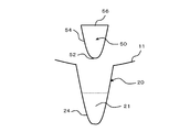
- FIG. 3 is a diagram illustrating an example of a method for embedding the metal member 50 in the space 21 on the back side of the groove 20.
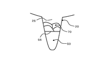
- FIG. 4 is a diagram for explaining an example of a method for forming the overlay by depositing the remaining space 26 of the groove portion 20 with the first welding material 70.
- FIG. 5 is a diagram illustrating an example of the outer shell member 10 that has been subjected to build-up welding using the first welding material 70.
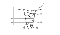
- FIG. 6 is a diagram illustrating an example of a method for overlay welding with the second welding material 40.
- FIG. 7 is a diagram illustrating an example of a metal member 80 used in the method for repairing a cast steel member according to the third embodiment.
- FIG. 8 is a diagram illustrating an example of a repair method for a cast steel member according to the fourth embodiment.
- FIG. 1 is a diagram showing an example of an outer shell member 10 of a steam turbine casing provided in a thermal power plant, a nuclear power plant, or the like.
- the outer shell member 10 of the steam turbine casing is made of a cast steel member such as CrMoV cast steel, and receives thermal stress as it starts and stops. As a result, the outer shell member 10 of the steam turbine casing is subjected to creep damage, and a crack 12 is generated on the inner surface 11.
- the entire crack 12 is removed by forming a groove 20 (groove) on the surface 11 of the outer shell member 10.
- a cutting line 13 surrounding the periphery of the surface portion of the crack 12 is formed, and the outer shell member 10 is formed along the formed cutting line 13 with a drill, an end mill, or the like.
- the surface 11 is cut in the depth direction.
- the groove 20 is a space whose cross-sectional shape is V-shaped or U-shaped, for example.
- the groove 20 formed as described above is made of a metal having higher ductility than the outer shell member 10 and has a shape corresponding to the shape of the space 21 on the back side of the groove 20.
- the member 50 is embedded.
- a metal member 50 having a height lower than the depth of the groove portion 20 and having substantially the same shape as the space 21 on the back side of the groove portion 20 is fitted into the groove portion 20, and the fitted metal
- the upper surface 56 (exposed surface) of the member 50 is hit with a hammer or the like (not shown). Thereby, the bottom surface 52 and the side surface 54 of the metal member 50 and the inner surface 24 of the groove part 20 are adhered as closely as possible.
- the metal member 50 is formed such that the height of the upper surface 56 (exposed surface) when the metal member 50 is embedded in the groove portion 20 is lower than the height of the surface 11 of the outer shell member 10.
- the material of the metal member 50 needs to be a metal having higher ductility than the outer shell member 10.
- the metal member 50 is made of pure nickel having a purity of 99.9% or more and inevitable impurities such as sulfur and phosphorus.
- a waste material of the outer shell member 10 which is a base material may be used as a material of the metal member 50. This is because the waste material has deteriorated and has higher ductility than the outer shell member 10 which is a base material.
- the remaining space 26 of the groove 20 after embedding the metal member 50 has approximately the same softness as the outer shell member 10 and can be welded to the outer shell member 10.
- the outer shell member 10 is build-up welded with a material (hereinafter referred to as a first welding material).
- the heated first welding material 70 is introduced into the upper surface 56 (exposed surface) of the metal member 50 embedded in the groove portion 20 to form a cladding.
- the remaining space 26 of the groove 20 after the metal member 50 is inserted is filled with the first welding material 70.
- this build-up welding is performed by, for example, a remelt process.
- the first welding material 70 in a molten state is supplied to the upper surface 56 of the metal member 50 using an arc welding machine or the like to form a build-up.
- the build-up is remelted (remelted) by heating the surface of the build-up that has been cooled and solidified using a TIG torch or the like.
- the build-up after remelting is naturally cooled. When it is naturally cooled, a new overlay is formed. The above processing is repeated.
- the material of the first welding material 70 is determined as follows, for example. That is, when the outer shell member 10 is jointly welded with the joint material welding material (overlay welding) and the welded portion is heat-treated, the softness (ductility, etc.) of the joint material welding material is measured in advance. A welding material having a softness equivalent to the softness is used.
- the softness of the joint material welding material (first welding material 70) is approximately equal to the softness of the joint material welding material when the cast steel member (outer shell member 10) is overlay welded with the joint material welding material and the welded portion is heat-treated.
- first welding material 70 is approximately equal to the softness of the joint material welding material when the cast steel member (outer shell member 10) is overlay welded with the joint material welding material and the welded portion is heat-treated.
- Such a first welding material 70 includes, for example, an alloy mainly composed of nickel.
- the nickel content is preferably 70% by weight or more.
- components other than nickel are chromium, for example.
- the chromium content is preferably 15% by weight or more.
- Components other than nickel and chromium are, for example, carbon, silicon, manganese, etc., excluding inevitable impurities such as sulfur and phosphorus.
- Nickel is soft and has high ductility, so it is difficult to harden even when quenched. If nickel is contained by 70% by weight or more, it is possible to effectively prevent the occurrence of cracks in the repaired cast steel member (outer shell member 10). In addition, welding with a welding material containing nickel is easy to perform on-site.
- the remaining space 26 of the groove 20 is build-up welded.
- FIG. 5 is a diagram illustrating an example of the outer shell member 10 that has been subjected to overlay welding using the first welding material.
- the height of the exposed surface 72 of the overlaying using the first welding material 70 corresponds to the height corresponding to the surface 11 of the outer shell member 10 ( For example, the process is performed until the height is approximately the same as the surface 11 of the outer shell member 10 before the groove 20 is formed.
- the groove portion 20 formed in the cast steel member has higher ductility than the cast steel member, and is located in the space 21 on the back side of the groove portion 20.
- Correspondingly shaped metal member 50 is embedded, and the remaining space 26 is welded with a welding material (first welding material 70) that is approximately the same as a cast steel member, so that the deformation of the base material after repair is made into metal.
- the welding material can prevent the crack 12 from being regenerated due to thermal stress while minimizing by the member 50. Thereby, the crack which generate
- the metal member 50 is directly embedded in the space 21 on the back side of the formed groove portion 20.
- the bottom surface 52 and the side surface 54 of the metal member 50 and the groove portion are provided.
- the inner surface 24 is not necessarily in close contact with the inner surface 24.
- a crack may occur again from the space (gap) between the two.
- the depth of the crack 12 is deep, and the thickness of the outer shell member 10 after the formation of the groove 20 is the required minimum thickness (for example, the outer shell member even if the product related to the outer shell member 10 is activated or stopped a predetermined number of times. In the case where the thickness of the outer shell member 10 is less than 10 which is necessary for 10 not to break, there is a high possibility that a crack will occur again.
- a welding material (hereinafter referred to as a second welding material) that is soft as substantially the same as the outer shell member 10 and can be welded to the outer shell member 10. 40).
- the second welding material 40 is put into the space 21 on the back side of the groove portion 20, and the overlay of the second welding material 40 is formed as in the first embodiment.
- the build-up welding with the second welding material 40 is performed at least until the thickness of the outer shell member 10 after the build-up welding becomes equal to or greater than the above-mentioned minimum required thickness.
- the upper surface 42 (exposed surface) of the overlay of the second welding material 40 is substantially flat.
- the raw material of the 2nd welding material 40 may be the same as that of Example 1, and may differ.
- the metal member 60 is embedded in the groove portion 20 on the overlay of the second welding material 40.
- the shape of the metal member 60 in the present embodiment is, for example, substantially the same shape as the space from the exposed surface of the second welding material 40 to the opening surface of the groove 20.
- a welding material made of a soft metal substantially equivalent to the cast steel member (outer shell member 10). 40), the thickness of the cast steel member reduced by forming the groove 20 can be recovered, and the strength of the cast steel member after repair can be maintained.
- the strength of the cast steel member after repair can be maintained.
- the necessary minimum wall thickness is estimated by, for example, FEM analysis (FEM: Finite Element Method).
- Example 3 The shape of the groove 20 (groove) varies depending on the progress of the crack 12. For example, when the crack 12 is large, the groove angle 20 must be formed large by adjusting the groove angle. Then, the welding range of this opening portion (the range of overlay welding with the first welding material 70) is increased, and as a result, the outer shell member 10 after welding repair is more easily deformed.
- a metal member having a shape that reduces the build-up welding at the opening of the groove 20 is used as in the repair method for the cast steel member according to the present embodiment.
- FIG. 7 is a diagram illustrating an example of a metal member 80 used in the method for repairing a cast steel member according to the third embodiment.
- the shape of the metal member 80 is a shape corresponding to the shape of the groove portion 20 excluding the peripheral portion on the opening side.
- the metal member 80 is a portion that fills the lower filling portion 82 that is a portion that fills the space 21 on the back side of the groove portion 20 and a portion of the space on the opening side of the groove portion 20 except the peripheral space 28. And an upper filling portion 84.
- the peripheral space 28 is formed as a new small groove.
- the thickness of the outer shell member 10 is equal to or more than the necessary minimum thickness by forming the groove.
- the space 28 on the peripheral edge portion on the opening side is build-up welded with the first welding material 70 (not shown).
- the metal member 80 of the cast steel member according to the present embodiment depends on, for example, the outer shell member 10 caused by thermal stress when the opening portion of the groove portion 20 is build-up welded with the first welding material 70.
- the deformation amount is estimated by FEM analysis, and the metal member 80 is used when the estimated deformation amount is larger than a predetermined threshold. Thereby, the deformation
- the groove portion 20 is filled with the metal member 80 having a shape corresponding to the space excluding the peripheral portion on the opening side of the groove portion 20, and the remaining space after filling.
- the amount of overlay welding can be minimized, and as a result, deformation of the cast steel member (outer shell member 10) after repair can be minimized.
- the generated crack 12 is large and the opening area of the groove 20 (groove) is widened, deformation of the surface portion of the cast steel member that is likely to be deformed can be effectively suppressed.
- Example 4 The repair methods according to Examples 1, 2, and 3 described above may be combined. For example, as shown in FIG. 8, a buildup of the second welding material 40 is formed in the space 21 on the back side of the groove portion 20 (Example 2), and a metal member 90 is embedded on the buildup (Example). 3) In the remaining space (remaining space 26) of the groove portion 20 after the metal member 80 is buried, a build-up with the first welding material 70 may be formed.
- the metal member 90 includes a lower filling portion 92 that is a portion excluding a portion that is already filled with the second welding material 40 in the space 21 on the back side of the groove portion 20, and an upper filling portion 94 that is similar to the third embodiment. And have.
Landscapes
- Engineering & Computer Science (AREA)
- Mechanical Engineering (AREA)
- Physics & Mathematics (AREA)
- Plasma & Fusion (AREA)
- Butt Welding And Welding Of Specific Article (AREA)
Abstract
本発明は、熱応力により鋳鋼部材10に発生した亀裂を補修する方法であって、鋳鋼部材10に溝部20を形成することにより亀裂12を除去し、形成した溝部12に、鋳鋼部材10よりも延性が高く、かつ、溝部20の奥側の空間に対応する形状を有する金属部材50を埋設し、金属部材50を埋設した後の溝部20の残空間26を、鋳鋼部材10と略同等に柔らかく、かつ鋳鋼部材10と溶接可能な溶接材料70で肉盛溶接する。なお、金属部材50は、純度が99.9%以上のニッケルを含む。溶接材料70は、ニッケルを70重量%以上含有する。
Description
本発明は、熱応力により鋳鋼部材に発生した亀裂を補修する方法に関する。
火力発電設備や原子力発電設備等における鋳鋼製の構造物は長期間に渡って高温・高圧条件におかれることが多いので、例えばその起動・停止によりかかる熱応力が原因で、当該構造物に亀裂が発生することがある。
このような亀裂を補修する場合、一般的には、亀裂の表面付近を削り、その上に肉盛りする方法がとられている。例えば、特許文献1には、ボイラ火炉の水壁を構成するメンブレンパネルの配管に生じている貫通き裂を削り取って補修部開先を形成し、この補修部開先にニッケルで肉盛り溶接して溶接部を形成し、メンブレンパネルの表面及び裏面の両面に対して全面的に外面肉盛溶接部を形成することが記載されている。
ところが、火力発電設備や原子力発電設備等における鋳鋼製の構造物には、蒸気タービン室や蒸気タービンの弁など大型のものが多いので、これらの構造物を工場に持ち帰って熱処理を行うとすると、そのための配管の切り離しや運搬作業に大きな手間がかかり、かつ費用もかかるため現実的ではない。
したがって、熱処理は現場で行わなければならず、この場合、ヒータによる部分加熱による溶接後熱処理やテンパービート法(焼き戻し処理)等が用いられる。しかし、現場で行うことができる熱処理の規模には限界があり、熱処理が不充分となり易い。そのため、補修部分が脆化して割れやすくなる(亀裂が再発生する)等の不具合が生じていた。特に、亀裂が深く必要な溶接量が大きい場合には、熱処理不足に起因する残留応力が発生し、当該構造物に変形が生じることがあった。
本発明はこのような事情に鑑みてなされたものであり、その目的は、熱応力により鋳鋼部材に発生した亀裂を効率よく補修する、鋳鋼部材の補修方法を提供することにある。
前述の目的を達成するための本発明の一つは、熱応力により鋳鋼部材に発生した亀裂を補修する方法であって、前記鋳鋼部材に溝部を形成することにより前記亀裂を除去し、前記形成した溝部に、前記鋳鋼部材よりも延性が高く、かつ、前記溝部の奥側の空間に対応する形状を有する金属部材を埋設し、前記金属部材を埋設した後の前記溝部の残空間を、前記鋳鋼部材と略同等に柔らかく、かつ前記鋳鋼部材と溶接可能な溶接材料で肉盛溶接する。
本発明のように、鋳鋼部材に形成した溝部に、鋳鋼部材よりも延性が高く、溝部の奥側の空間に対応する形状の金属部材を埋設し、その残空間を、鋳鋼部材と略同等に柔らかい溶接材料で肉盛溶接することで、補修後の母材の変形を金属部材により最小限に抑えつつ、かつ熱応力による亀裂の再発生を溶接材料により防ぐことができる。これにより、熱応力により鋳鋼部材に発生した亀裂を効率よく補修することができる。
具体的には、例えば、前記溶接材料は、前記鋳鋼部材を共材溶接材料で肉盛溶接しその溶接部を熱処理した場合の当該共材溶接材料と略同等の柔らかさを有する溶接材料である。
このように、溶接材料を、鋳鋼部材を共材溶接材料で肉盛溶接しその溶接部を熱処理した場合の当該共材溶接材料の柔らかさと略同じにするにすることで、溶接後熱処理を行わずとも、溶接後の母材の熱応力による変形を防ぐことができる。
また、本発明の他の一つは、前記金属部材は、純度が99.9%以上のニッケルを含む。金属部材として純度が高く延性の高いニッケルを用いることにより、補修後の鋳鋼部材にかかる熱応力を効果的に緩和することができる。
また、本発明の他の一つは、前記溶接材料はニッケルを70重量%以上含有する。ニッケルは柔らかく延性が高いので、急冷しても硬化しにくい。本発明者らは、ニッケルが70重量%以上含有されていれば、補修後の鋳鋼部材における亀裂の再発生を効果的に防ぐことができることを発見した。また、ニッケルを含む溶接材料による溶接は、現場での作業も容易である。
また、本発明の他の一つは、前記金属部材を埋設する前に、前記鋳鋼部材と略同等に柔らかく、かつ前記鋳鋼部材と溶接可能な溶接材料で、前記溝部の奥側の空間を肉盛溶接する。
本発明のように、金属部材を埋設する前に、鋳鋼部材と略同等に柔らかい金属からなる溶接材料で溝部の奥側を肉盛溶接しておくことで、溝部を形成したことにより減少した鋳鋼部材の肉厚を回復させ、補修後の鋳鋼部材の強度を維持することができる。
また、本発明の他の一つは、前記溝部を形成した後の前記鋳鋼部材の肉厚が所定の値未満である場合には、前記金属部材を埋設する前に、前記鋳鋼部材の肉厚が前記所定の値に達するまで、前記溝部の奥側の空間を前記溶接材料で肉盛溶接する。
本発明のように、溝部を形成した後の鋳鋼部材の肉厚が所定の値未満である場合に、鋳鋼部材の肉厚がその値に達するまで、溝部の奥側の空間を事前に肉盛溶接しておくことで、例えば、前記所定の値を必要最小肉厚に設定することにより、鋳鋼部材の安全な使用に必要な肉厚を肉盛溶接により確実に確保することができる。
また、本発明の他の一つは、前記溝部の空間のうち前記溝部の開口側の周縁を除いた空間に対応する形状を有する前記金属部材を埋設し、さらに、前記開口側の周縁の空間を前記溶接材料で肉盛溶接する。
本発明のように、溝部に、溝部の開口側の周縁部を除いた空間に対応する形状の金属部材を充填し、充填後の残りの空間を肉盛溶接することで、肉盛溶接の量を必要最小限に抑え、その結果、補修後の鋳鋼部材の変形を最小限に抑えることができる。特に、発生した亀裂が大きく溝部(開先)の開口面積が広くなる場合に、変形が起きやすい鋳鋼部材の表面部の変形を効果的に抑えることができる。
また、本発明の他の一つは、前記溝部の開口側の空間を前記溶接材料で肉盛溶接することにより生じる、前記熱応力による前記鋳鋼部材の変形量をFEM解析により推定し、推定した前記変形量が所定の閾値よりも大きい場合に、前記溝部の空間のうち前記溝部の開口側の周縁を除いた空間に対応する形状を有する前記金属部材を埋設し、さらに、前記開口側の周縁の空間を前記溶接材料で肉盛溶接する。
本発明のように、溝部の開口側の空間を肉盛溶接した場合の熱応力による鋳鋼部材の変形量をFEM解析により推定し、推定した変形量が所定の閾値よりも大きい場合に、前記工程を行うことで、肉盛溶接による鋳鋼部材の変形を予め確実に抑えることができる。
本発明によれば、熱応力により鋳鋼部材に発生した亀裂を効率よく補修することができる。
<実施例1>
本発明の各実施例について、図面を参照しつつ説明する。
本発明の各実施例について、図面を参照しつつ説明する。
図1は、火力発電所や原子力発電所等に設けられる蒸気タービン車室の外殻部材10の一例を示す図である。同図に示すように、蒸気タービン車室の外殻部材10は、CrMoV鋳鋼などの鋳鋼部材からなり、その起動・停止に伴って熱応力を受ける。これにより蒸気タービン車室の外殻部材10はクリープ損傷を受け、内側の表面11に亀裂12が発生する。
まず、本実施例に係る補修方法では、図2に示すように、外殻部材10の表面11に溝部20(開先)を形成することにより、亀裂12全体を除去する。
具体的には、例えば、外殻部材10の表面11において、亀裂12の表面部分の周囲を囲う切削線13を形成し、ドリルやエンドミル等で、形成した切削線13に沿って外殻部材10の表面11を深さ方向に切削する。なお、溝部20は、例えば、その断面形状がV字状又はU字状の空間とする。
次に、図3に示すように、前記で形成した溝部20に、外殻部材10よりも延性が高い金属からなり、かつ、溝部20の奥側の空間21の形状に対応する形状を有する金属部材50を埋設する。
具体的には、例えば、溝部20の深さよりもその高さが低く、溝部20の奥側の空間21と略同一の形状を有する金属部材50を溝部20に嵌合させ、嵌合させた金属部材50の上面56(露出面)をハンマー等(不図示)で叩く。これにより、金属部材50の底面52及び側面54と、溝部20の内表面24とをできるだけ密着させる。
すなわち、金属部材50は、自身を溝部20に埋設したときの上面56(露出面)の高さが外殻部材10の表面11の高さよりも低くなるように成形されている。
金属部材50の素材は、外殻部材10よりも高い延性を有している金属であることが必要である。例えば、金属部材50は、純度が99.9%以上の純ニッケル、及び、硫黄やリン等の不可避不純物からなる。
このように、金属部材50として純度が高く延性の高いニッケルを用いることにより、鋳鋼部材(外殻部材10)にかかる熱応力を効果的に緩和することができる。
なお、金属部材50の素材としては、純ニッケルに代えて、母材である外殻部材10の廃材を用いてもよい。廃材は劣化しており、母材である外殻部材10よりも高い延性を有しているためである。
次に、図4に示すように、金属部材50を埋設した後の溝部20の残空間26に、外殻部材10とおおよそ同等の柔らかさを有し、かつ外殻部材10と溶接可能な溶接材料(以下、第1溶接材料という)で、外殻部材10を肉盛溶接する。
具体的には、例えば、溝部20に埋設した金属部材50の上面56(露出面)に、溶接トーチ等を用いて、加熱された第1溶接材料70を投入して肉盛を形成することで、金属部材50を挿入した後の、溝部20の残空間26を第1溶接材料70で充填する。
具体的には、この肉盛溶接は、例えばリメルト処理により行う。例えば、図4に示すように、アーク溶接機等を用いて金属部材50の上面56に溶融状態の第1溶接材料70を供給して肉盛を形成する。そして、冷却し固化させた当該肉盛の表面を、TIGトーチ等を用いて加熱することにより、当該肉盛をリメルト(再溶融)する。そして、リメルト後の肉盛を自然冷却させる。自然冷却させたら、新たな肉盛を形成する。以上の処理を繰り返す。
第1溶接材料70の素材は、例えば、以下のようにして定める。すなわち、外殻部材10を共材溶接材料で共材溶接(肉盛溶接)してその溶接部を熱処理した場合における、当該共材溶接材料の柔らかさ(延性等)を予め測定しておき、その柔らかさと同等の柔らかさを有する溶接材料を用いる。
このように、溶接材料(第1溶接材料70)を、鋳鋼部材(外殻部材10)を共材溶接材料で肉盛溶接しその溶接部を熱処理した場合の当該共材溶接材料の柔らかさと略同じにすることで、溶接後熱処理を行わずとも、溶接後の母材の熱応力による変形を防ぐことができる。
このような第1溶接材料70としては、例えば、ニッケルを主成分とする合金がある。この場合のニッケルの含有量は、70重量%以上であることが好ましい。また、ニッケル以外の成分は、例えば、クロムである。クロムの含有量は、15重量%以上であることが好ましい。ニッケル及びクロム以外の成分は、硫黄やリン等の不可避不純物を除くと、例えば、炭素、ケイ素、マンガン等である。
ニッケルは柔らかく延性が高いので、急冷しても硬化しにくい。ニッケルが70重量%以上含有されていれば、補修後の鋳鋼部材(外殻部材10)における亀裂の再発生を効果的に防ぐことができる。また、ニッケルを含む溶接材料による溶接は、現場での作業も容易である。
以上のリメルト処理を行うことで、溝部20の残空間26を肉盛溶接する。
図5は、第1溶接材料による肉盛溶接を終えた外殻部材10の一例を示す図である。第1溶接材料70による肉盛溶接は、例えば、同図に示すように、第1溶接材料70による肉盛の露出面72の高さが、外殻部材10の表面11と対応する高さ(例えば、溝部20を形成する前の外殻部材10の表面11と略同じ高さ)になるまで行う。
以上のように、本実施形態の鋳鋼部材の補修方法によれば、鋳鋼部材(外殻部材10)に形成した溝部20に、鋳鋼部材よりも延性が高く、溝部20の奥側の空間21に対応する形状の金属部材50を埋設し、その残空間26を、鋳鋼部材と略同等に柔らかい溶接材料(第1溶接材料70)で肉盛溶接することで、補修後の母材の変形を金属部材50により最小限に抑えつつ、かつ熱応力による亀裂12の再発生を溶接材料により防ぐことができる。これにより、熱応力により鋳鋼部材に発生した亀裂を効率よく補修することができる。
<実施例2>
実施例1では、形成した溝部20の奥側の空間21に直接、金属部材50を埋設したが、金属部材50は一般に変形しにくい性質があるため、金属部材50の底面52及び側面54と溝部20の内表面24との間は、必ずしも密着するとは限らない。この場合、両者の間の空間(隙間)から再び亀裂が発生する可能性もある。特に、亀裂12の深さが深く、溝部20の形成後の外殻部材10の肉厚が必要最小肉厚(例えば、外殻部材10に係る製品が所定回数起動又は停止しても外殻部材10が破断しないために必要な外殻部材10の肉厚)未満となっている場合には、再び亀裂が発生する可能性が高くなる。
実施例1では、形成した溝部20の奥側の空間21に直接、金属部材50を埋設したが、金属部材50は一般に変形しにくい性質があるため、金属部材50の底面52及び側面54と溝部20の内表面24との間は、必ずしも密着するとは限らない。この場合、両者の間の空間(隙間)から再び亀裂が発生する可能性もある。特に、亀裂12の深さが深く、溝部20の形成後の外殻部材10の肉厚が必要最小肉厚(例えば、外殻部材10に係る製品が所定回数起動又は停止しても外殻部材10が破断しないために必要な外殻部材10の肉厚)未満となっている場合には、再び亀裂が発生する可能性が高くなる。
そのような場合は、図6に示すように、金属部材50を埋設する前に、外殻部材10と略同等に柔らかく、かつ外殻部材10と溶接可能な溶接材料(以下、第2溶接材料40という)で肉盛溶接する。
具体的には、第2溶接材料40を溝部20の奥側の空間21に投入し、実施例1と同様に、第2溶接材料40の肉盛を形成する。
第2溶接材料40による肉盛溶接は、少なくとも、当該肉盛溶接後の外殻部材10の厚さが、上記の必要最小肉厚以上の厚さになるまで行う。なお、この第2溶接材料40の肉盛の上面42(露出面)は略平坦となっていることが好ましい。なお、第2溶接材料40の素材は実施例1と同様でもよいし、異なっていてもよい。
次に、図6に示しているように、第2溶接材料40による肉盛の上に、金属部材60を溝部20に埋設する。
本実施例における金属部材60の形状は、例えば、第2溶接材料40による肉盛の露出面から溝部20の開口面までの空間と略同一の形状とする。
そして、実施例1と同様に、金属部材60を埋設した溝部20の残りの空間(残空間26)を、第1溶接材料70で肉盛溶接する。
以上のように、本実施例の鋳鋼部材の補修方法によれば、金属部材60を埋設する前に、鋳鋼部材(外殻部材10)と略同等に柔らかい金属からなる溶接材料(第2溶接材料40)で溝部20の奥側を肉盛溶接しておくことで、溝部20を形成したことにより減少した鋳鋼部材の肉厚を回復させ、補修後の鋳鋼部材の強度を維持することができる。
例えば、亀裂12の除去後の鋳鋼部材の肉厚が必要最小肉厚未満になっている場合でも、補修後の鋳鋼部材の強度を保つことができる。なお、必要最小肉厚は、例えばFEM解析(FEM: Finite Element Method)により推定する。
<実施例3>
溝部20(開先)の形状は、亀裂12の進展状況に応じて異なる。例えば、亀裂12が大きい場合には、開先の角度を調節して溝部20の開口を大きく形成しなければならない。すると、この開口の部分の溶接範囲(第1溶接材料70による肉盛溶接の範囲)が大きくなり、その結果、溶接補修後の外殻部材10がより変形し易くなる。
溝部20(開先)の形状は、亀裂12の進展状況に応じて異なる。例えば、亀裂12が大きい場合には、開先の角度を調節して溝部20の開口を大きく形成しなければならない。すると、この開口の部分の溶接範囲(第1溶接材料70による肉盛溶接の範囲)が大きくなり、その結果、溶接補修後の外殻部材10がより変形し易くなる。
このような場合、本実施例に係る鋳鋼部材の補修方法のように、溝部20の開口における肉盛溶接を少なくするような形状の金属部材を用いる。
図7は、実施例3に係る鋳鋼部材の補修方法において使用される金属部材80の一例を示す図である。同図に示すように、本実施例に係る補修方法では、金属部材80の形状を、溝部20の形状のうち開口側の周縁部を除いた部分の形状に対応する形状としている。
すなわち、金属部材80は、溝部20の奥側の空間21を充填する部分である下方充填部82と、溝部20の開口側の空間のうち、その周縁部の空間28を除く部分を充填する部分である上方充填部84とで構成されている。
このような金属部材60を溝部20に埋設することにより、上記の周縁部の空間28が、新たな小さな開先として形成される。なお、この場合、開先が形成されることにより外殻部材10の厚みが必要最小肉厚以上になっていることが好ましい。
そして、実施例1と同様に、上記の開口側の周縁部の空間28を、第1溶接材料70で肉盛溶接する(不図示)。
なお、本実施例に係る鋳鋼部材の金属部材80を使用するか否かは、例えば、溝部20の開口部分を第1溶接材料70で肉盛溶接した場合の、熱応力による外殻部材10の変形量をFEM解析により推定し、推定した変形量が所定の閾値よりも大きい場合に当該金属部材80を使用するものとする。これにより、肉盛溶接による鋳鋼部材(外殻部材10)の変形を予め確実に抑えることができる。
以上のように、本実施例の鋳鋼部材の補修方法では、溝部20に、溝部20の開口側の周縁部を除いた空間に対応する形状の金属部材80を充填し、充填後の残りの空間を肉盛溶接することで、肉盛溶接の量を必要最小限に抑え、その結果、補修後の鋳鋼部材(外殻部材10)の変形を最小限に抑えることができる。特に、発生した亀裂12が大きく溝部20(開先)の開口面積が広くなる場合に、変形が起きやすい鋳鋼部材の表面部の変形を効果的に抑えることができる。
<実施例4>
前記に説明した実施例1、2、3に係る補修方法は、それぞれ組み合わせてもよい。例えば、図8に示すように、溝部20の奥側の空間21に第2溶接材料40による肉盛を形成し(実施例2)、この肉盛の上に金属部材90を埋設し(実施例3)、金属部材80を埋設した後の溝部20の残りの空間(残空間26)に、第1溶接材料70による肉盛を形成してもよい。なお、金属部材90は、溝部20の奥側の空間21のうち第2溶接材料40が既に充填されている部分を除く部分である下方充填部92と、実施例3と同様の上方充填部94とを有する。
前記に説明した実施例1、2、3に係る補修方法は、それぞれ組み合わせてもよい。例えば、図8に示すように、溝部20の奥側の空間21に第2溶接材料40による肉盛を形成し(実施例2)、この肉盛の上に金属部材90を埋設し(実施例3)、金属部材80を埋設した後の溝部20の残りの空間(残空間26)に、第1溶接材料70による肉盛を形成してもよい。なお、金属部材90は、溝部20の奥側の空間21のうち第2溶接材料40が既に充填されている部分を除く部分である下方充填部92と、実施例3と同様の上方充填部94とを有する。
以上の実施例の説明は、本発明の理解を容易にするためのものであり、本発明を限定するものではない。本発明はその趣旨を逸脱することなく、変更、改良され得ると共に本発明にはその等価物が含まれる。
10 外殻部材、11 表面、12 亀裂、13 切削線、20 溝部、21 奥側の空間、24 内表面、26 残空間、28 周縁部の空間、40 第2溶接材料、42 上面、50 金属部材、52 底面、54 側面、56 上面、60 金属部材、70 第1溶接材料、72 露出面、80 金属部材、82 下方充填部、84 上方充填部、90 金属部材、92 下方充填部、94 上方充填部
Claims (8)
- 熱応力により鋳鋼部材に発生した亀裂を補修する方法であって、
前記鋳鋼部材に溝部を形成することにより前記亀裂を除去し、
前記形成した溝部に、前記鋳鋼部材よりも延性が高く、かつ、前記溝部の奥側の空間に対応する形状を有する金属部材を埋設し、
前記金属部材を埋設した後の前記溝部の残空間を、前記鋳鋼部材と略同等に柔らかく、かつ前記鋳鋼部材と溶接可能な溶接材料で肉盛溶接する、
鋳鋼部材の補修方法。 - 前記溶接材料は、前記鋳鋼部材を共材溶接材料で肉盛溶接しその溶接部を熱処理した場合の当該共材溶接材料と略同等の柔らかさを有する溶接材料である、請求項1に記載の鋳鋼部材の補修方法。
- 前記金属部材は、純度が99.9%以上のニッケルを含む、請求項1に記載の鋳鋼部材の補修方法。
- 前記溶接材料はニッケルを70重量%以上含有する、請求項1又は2に記載の鋳鋼部材の補修方法。
- 前記金属部材を埋設する前に、前記鋳鋼部材と略同等に柔らかく、かつ前記鋳鋼部材と溶接可能な溶接材料で、前記溝部の奥側の空間の一部を肉盛溶接する、請求項1に記載の鋳鋼部材の補修方法。
- 前記溝部を形成した後の前記鋳鋼部材の肉厚が所定の値未満である場合には、前記鋳鋼部材の肉厚が前記所定の値に達するまで、前記金属部材を埋設する前に、前記溝部の奥側の空間を前記溶接材料で肉盛溶接する、請求項5に記載の鋳鋼部材の補修方法。
- 前記溝部の空間のうち前記溝部の開口側の周縁を除いた空間に対応する形状を有する前記金属部材を埋設し、さらに、前記開口側の周縁の空間を前記溶接材料で肉盛溶接する、請求項1に記載の鋳鋼部材の補修方法。
- 前記溝部の開口側の空間を前記溶接材料で肉盛溶接することにより生じる、前記熱応力による前記鋳鋼部材の変形量をFEM解析により推定し、推定した前記変形量が所定の閾値よりも大きい場合に、前記溝部の空間のうち前記溝部の開口側の周縁を除いた空間に対応する形状を有する前記金属部材を埋設し、さらに、前記開口側の周縁の空間を前記溶接材料で肉盛溶接する、請求項7に記載の鋳鋼部材の補修方法。
Priority Applications (2)
| Application Number | Priority Date | Filing Date | Title |
|---|---|---|---|
| JP2017539375A JP6217889B1 (ja) | 2017-01-12 | 2017-01-12 | 鋳鋼部材の補修方法 |
| PCT/JP2017/000761 WO2018131107A1 (ja) | 2017-01-12 | 2017-01-12 | 鋳鋼部材の補修方法 |
Applications Claiming Priority (1)
| Application Number | Priority Date | Filing Date | Title |
|---|---|---|---|
| PCT/JP2017/000761 WO2018131107A1 (ja) | 2017-01-12 | 2017-01-12 | 鋳鋼部材の補修方法 |
Publications (1)
| Publication Number | Publication Date |
|---|---|
| WO2018131107A1 true WO2018131107A1 (ja) | 2018-07-19 |
Family
ID=60156753
Family Applications (1)
| Application Number | Title | Priority Date | Filing Date |
|---|---|---|---|
| PCT/JP2017/000761 Ceased WO2018131107A1 (ja) | 2017-01-12 | 2017-01-12 | 鋳鋼部材の補修方法 |
Country Status (2)
| Country | Link |
|---|---|
| JP (1) | JP6217889B1 (ja) |
| WO (1) | WO2018131107A1 (ja) |
Citations (3)
| Publication number | Priority date | Publication date | Assignee | Title |
|---|---|---|---|---|
| JPH0392615A (ja) * | 1989-09-05 | 1991-04-17 | Ishikawajima Harima Heavy Ind Co Ltd | 段付きロッドの応力集中緩和方法 |
| JP2008229719A (ja) * | 2007-03-22 | 2008-10-02 | United Technol Corp <Utc> | タービンエンジン構成部品などのワーク内のクラックを補修する方法 |
| JP2016132072A (ja) * | 2015-01-21 | 2016-07-25 | 中国電力株式会社 | 鋳鋼部材の補修方法 |
-
2017
- 2017-01-12 WO PCT/JP2017/000761 patent/WO2018131107A1/ja not_active Ceased
- 2017-01-12 JP JP2017539375A patent/JP6217889B1/ja not_active Expired - Fee Related
Patent Citations (3)
| Publication number | Priority date | Publication date | Assignee | Title |
|---|---|---|---|---|
| JPH0392615A (ja) * | 1989-09-05 | 1991-04-17 | Ishikawajima Harima Heavy Ind Co Ltd | 段付きロッドの応力集中緩和方法 |
| JP2008229719A (ja) * | 2007-03-22 | 2008-10-02 | United Technol Corp <Utc> | タービンエンジン構成部品などのワーク内のクラックを補修する方法 |
| JP2016132072A (ja) * | 2015-01-21 | 2016-07-25 | 中国電力株式会社 | 鋳鋼部材の補修方法 |
Also Published As
| Publication number | Publication date |
|---|---|
| JPWO2018131107A1 (ja) | 2019-01-17 |
| JP6217889B1 (ja) | 2017-10-25 |
Similar Documents
| Publication | Publication Date | Title |
|---|---|---|
| JP5996789B2 (ja) | 鋳鋼部材の補修方法 | |
| US11167369B2 (en) | Method of manufacturing welded structure of ferritic heat-resistant steel and welded structure of ferritic heat-resistant steel | |
| JP5953272B2 (ja) | ボイラ用メンブレンパネルの溶接部の予防保全補修方法 | |
| CN109079420A (zh) | 一种铸件缺陷消除方法 | |
| US20190211411A1 (en) | Method of Manufacturing Welded Structure of Ferritic Heat-Resistant Steel and Welded Structure of Ferritic Heat-Resistant Steel | |
| JP2012115886A (ja) | 構造物の溶接方法 | |
| JP6217891B1 (ja) | 鋳鋼部材の補修方法 | |
| JP2013107101A (ja) | 金属部品の修理方法 | |
| JP2010201491A (ja) | 耐熱鋼品の溶接補修方法及び溶接補修部を有する耐熱鋼品 | |
| JP6217889B1 (ja) | 鋳鋼部材の補修方法 | |
| JP2016112574A (ja) | 鋳鋼部材の亀裂補修方法 | |
| JP5337014B2 (ja) | 溶接継手部のクリープ強度向上構造 | |
| JP6373303B2 (ja) | 連続鋳造鋳型の補修方法 | |
| JP6118714B2 (ja) | 厚肉大径管の溶接継手構造とその溶接施工方法 | |
| JP6217892B1 (ja) | 鋳鋼部材の補修方法 | |
| JP2007021530A (ja) | 鋳鋼品の溶接補修方法及び溶接補修部を有する鋳鋼品 | |
| JP5050537B2 (ja) | 厚鋼板の切断方法 | |
| JP2013039596A (ja) | 金属部品の修理方法 | |
| JP6540045B2 (ja) | 鋳鋼部材の補修方法 | |
| JP2016132072A (ja) | 鋳鋼部材の補修方法 | |
| EP1561827A1 (en) | Method of welding a ferritic steel comprising a post weld heat treatment and cold working on the weld | |
| JP5473887B2 (ja) | スメルトスパウト及びその製造方法 | |
| JP6233073B2 (ja) | スリット付き連続鋳造用ロールの再生方法 | |
| JP6984481B2 (ja) | 鋳鋼部材の溶接方法 | |
| Kim et al. | Welding characteristic evaluation of GMAW and laser cladding for the gas turbine 1st blade |
Legal Events
| Date | Code | Title | Description |
|---|---|---|---|
| ENP | Entry into the national phase |
Ref document number: 2017539375 Country of ref document: JP Kind code of ref document: A |
|
| 121 | Ep: the epo has been informed by wipo that ep was designated in this application |
Ref document number: 17891441 Country of ref document: EP Kind code of ref document: A1 |
|
| NENP | Non-entry into the national phase |
Ref country code: DE |
|
| 122 | Ep: pct application non-entry in european phase |
Ref document number: 17891441 Country of ref document: EP Kind code of ref document: A1 |