WO2018128146A1 - 分光測定方法および分光測定装置 - Google Patents
分光測定方法および分光測定装置 Download PDFInfo
- Publication number
- WO2018128146A1 WO2018128146A1 PCT/JP2017/046932 JP2017046932W WO2018128146A1 WO 2018128146 A1 WO2018128146 A1 WO 2018128146A1 JP 2017046932 W JP2017046932 W JP 2017046932W WO 2018128146 A1 WO2018128146 A1 WO 2018128146A1
- Authority
- WO
- WIPO (PCT)
- Prior art keywords
- illumination light
- image
- spectroscopic
- sample
- light
- Prior art date
- Legal status (The legal status is an assumption and is not a legal conclusion. Google has not performed a legal analysis and makes no representation as to the accuracy of the status listed.)
- Ceased
Links
Images





Classifications
-
- G—PHYSICS
- G01—MEASURING; TESTING
- G01J—MEASUREMENT OF INTENSITY, VELOCITY, SPECTRAL CONTENT, POLARISATION, PHASE OR PULSE CHARACTERISTICS OF INFRARED, VISIBLE OR ULTRAVIOLET LIGHT; COLORIMETRY; RADIATION PYROMETRY
- G01J3/00—Spectrometry; Spectrophotometry; Monochromators; Measuring colours
- G01J3/02—Details
- G01J3/10—Arrangements of light sources specially adapted for spectrometry or colorimetry
-
- G—PHYSICS
- G01—MEASURING; TESTING
- G01J—MEASUREMENT OF INTENSITY, VELOCITY, SPECTRAL CONTENT, POLARISATION, PHASE OR PULSE CHARACTERISTICS OF INFRARED, VISIBLE OR ULTRAVIOLET LIGHT; COLORIMETRY; RADIATION PYROMETRY
- G01J3/00—Spectrometry; Spectrophotometry; Monochromators; Measuring colours
- G01J3/28—Investigating the spectrum
- G01J3/30—Measuring the intensity of spectral lines directly on the spectrum itself
- G01J3/36—Investigating two or more bands of a spectrum by separate detectors
-
- G—PHYSICS
- G01—MEASURING; TESTING
- G01J—MEASUREMENT OF INTENSITY, VELOCITY, SPECTRAL CONTENT, POLARISATION, PHASE OR PULSE CHARACTERISTICS OF INFRARED, VISIBLE OR ULTRAVIOLET LIGHT; COLORIMETRY; RADIATION PYROMETRY
- G01J3/00—Spectrometry; Spectrophotometry; Monochromators; Measuring colours
- G01J3/46—Measurement of colour; Colour measuring devices, e.g. colorimeters
-
- G—PHYSICS
- G01—MEASURING; TESTING
- G01N—INVESTIGATING OR ANALYSING MATERIALS BY DETERMINING THEIR CHEMICAL OR PHYSICAL PROPERTIES
- G01N21/00—Investigating or analysing materials by the use of optical means, i.e. using sub-millimetre waves, infrared, visible or ultraviolet light
- G01N21/17—Systems in which incident light is modified in accordance with the properties of the material investigated
- G01N21/25—Colour; Spectral properties, i.e. comparison of effect of material on the light at two or more different wavelengths or wavelength bands
- G01N21/27—Colour; Spectral properties, i.e. comparison of effect of material on the light at two or more different wavelengths or wavelength bands using photo-electric detection ; circuits for computing concentration
-
- G—PHYSICS
- G01—MEASURING; TESTING
- G01N—INVESTIGATING OR ANALYSING MATERIALS BY DETERMINING THEIR CHEMICAL OR PHYSICAL PROPERTIES
- G01N21/00—Investigating or analysing materials by the use of optical means, i.e. using sub-millimetre waves, infrared, visible or ultraviolet light
- G01N21/62—Systems in which the material investigated is excited whereby it emits light or causes a change in wavelength of the incident light
- G01N21/63—Systems in which the material investigated is excited whereby it emits light or causes a change in wavelength of the incident light optically excited
- G01N21/65—Raman scattering
-
- G—PHYSICS
- G02—OPTICS
- G02B—OPTICAL ELEMENTS, SYSTEMS OR APPARATUS
- G02B21/00—Microscopes
Definitions
- the present invention relates to a spectroscopic measurement method and a spectroscopic measurement device, and more particularly to a Raman spectroscopic measurement method and a Raman spectroscopic device.
- the Raman spectroscopic measurement apparatus for specifying a substance structure by using Raman scattered light generated when a substance is irradiated with laser light.
- the Raman scattered light is generated with a unique spectrum according to the molecular structure of the substance at the irradiation point of the laser beam.
- the Raman spectroscopic measurement apparatus includes a light source such as a laser beam for generating Raman scattered light, a camera for confirming an irradiation point of the laser beam in addition to a Raman spectroscope (detector), and an illumination light source for photographing.
- a light source such as a laser beam for generating Raman scattered light
- a camera for confirming an irradiation point of the laser beam in addition to a Raman spectroscope (detector)
- an illumination light source for photographing.
- a laser beam half mirror (translucent mirror) and a photographing illumination light source half mirror are arranged on the optical axis of a camera lens.
- a part of the laser light reflected by the half mirror and a part of the illumination light for photographing reflected by another half mirror are made to coincide on the optical axis connecting the camera and the lens.
- Patent Document 1 captures an irradiation point of a laser beam irradiated to an arbitrary position of a sample and specifies a structure of the sample at the irradiation point by spectroscopic measurement. For this reason, the micro Raman spectroscopic device shows a structure different from the structure at the irradiation point unless foreign matter or the like is attached to the irradiation point or unless the accuracy rate of structure identification based on the spectroscopic measurement is 100%. Spectroscopic measurement results may be obtained. However, the microscopic Raman spectroscopic device cannot determine whether or not the determination of the structure based on the spectroscopic measurement result of the single irradiation point is correct.
- the microscopic Raman spectroscopic device can specify the structure from the spectroscopic measurement results at a plurality of irradiation points arranged in a two-dimensional plane by scanning spectroscopic measurement.
- the scanning microscopic Raman spectroscopic device cannot determine whether the determination based on the spectroscopic measurement result is correct as in the case of a single irradiation point.
- the structure other than the irradiation point can only be estimated from the surrounding spectroscopic measurement results, and the sample is composed of the same structure. The specified area cannot be accurately identified.
- An object of the present invention is to provide a spectroscopic measurement method and a spectroscopic measurement apparatus that can accurately and accurately specify a structure constituting a predetermined region in a short time.
- the sample illumination light and the spectral illumination light are irradiated onto the sample, and the sample is excited by the spectral illumination light while the image of the sample and the irradiation point of the spectral illumination light are acquired by the photographing camera.
- a method of irradiating the sample with the photographing illumination light and irradiating the spectroscopic illumination light to a plurality of locations, an image of the form of the sample, and the spectroscopy An image acquisition step for acquiring images of a plurality of irradiation points of illumination light for light, a spectroscopic measurement step for spectroscopically measuring light excited from a plurality of irradiation points by the illumination light for spectroscopy, and a form of the acquired sample
- the measurement results Based on the spectral measurement results of the plurality of irradiation points of the spectroscopic illumination light in each image region, superimposed on the plurality of irradiation points of the spectroscopic illumination light in the image in the form of the sample divided into image regions
- the region determination step the number of irradiation points of spectroscopic illumination light having spectroscopic measurement results indicating the same structure with respect to a plurality of irradiation points of the spectroscopic illumination light in one image region is calculated.
- the ratio is equal to or greater than a predetermined value, the structure of the image region is specified as the structure of the spectroscopic measurement result.
- the spectroscopic illumination light is divided into a plurality of spectroscopic illumination lights by an illumination light splitting unit and simultaneously irradiated onto the sample, and the image acquisition step and the spectroscopic measurement step are performed simultaneously.
- the image information is composed of at least one information of hue, brightness, saturation, and luminance.
- a spectroscopic measurement apparatus that performs the spectroscopic measurement method, a spectroscopic illumination light source having a predetermined wavelength, a spectroscope, a photographing camera, a photographing illumination light source, a total reflection mirror in which a pinhole is formed, A dichroic mirror that transmits only the spectroscopic illumination light having a predetermined wavelength and light having a shorter wavelength than the spectroscopic illumination light, and the total reflection mirror and the dichroic mirror are disposed on an optical axis of the spectroscopic illumination light.
- the spectral illumination light from the spectral illumination light source passes through the pinhole of the total reflection mirror and is irradiated on the sample, and the light excited by the spectral illumination light irradiated on the sample is the dichroic
- the imaging illumination light reflected from the mirror and incident on the spectroscope is reflected by the total reflection mirror and reflected on the optical axis of the spectral illumination light.
- the illumination light for photographing that is irradiated on the sample in a state where the optical axis of the sample is matched and reflected from the sample is reflected on the total reflection mirror in a state where the optical axis is matched with the optical axis of the spectroscopic illumination light. And is incident on the photographing camera.
- the present invention has the following effects.
- the spectroscopic illumination light in the image region is irradiated by applying the spectroscopic measurement results at a plurality of locations in the image region set as a range composed of one structure to the image region.
- a structure of the entire image region including the missing part is specified.
- the structure constituting the predetermined region can be accurately identified in a short time.
- the measurement time can be shortened as compared with the case where the measurement density is increased and the image area is measured.
- one result is determined from all the spectroscopic measurement results in the image area, so that the structure of the entire image area can be accurately specified even if the measurement result includes an erroneous determination. . Thereby, the structure which comprises a predetermined area
- the spectroscopic illumination light is irradiated to a plurality of locations in the image area at a time.
- region can be pinpointed accurately.
- the measurement time can be shortened as compared with the case where the measurement density is increased and the image area is measured.
- an image in the form of a sample is appropriately divided into image regions according to the form. Thereby, the structure which comprises a predetermined area
- a plurality of spectroscopic illumination lights are irradiated at once while maintaining the output without being affected by the optical system, and the spectroscopic illumination is applied to the image area by applying the spectroscopic measurement result to the image area.
- a structure of the entire image region including a portion not irradiated with light is specified. Thereby, the structure which comprises a predetermined area
- the measurement time can be shortened as compared with the case where the measurement density is increased and the image area is measured.
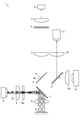
- a Raman spectroscopic measurement apparatus 1 which is an embodiment of a Raman spectroscopic measurement apparatus that is a spectroscopic measurement apparatus that performs a spectroscopic measurement method will be described with reference to FIGS. 1 and 2.
- the Raman spectroscopic measurement apparatus 1 will be specifically described as the spectroscopic measurement apparatus.
- the present invention is not limited to this, and the spectroscopic measurement apparatus using various spectroscopic illumination lights, such as a fluorescence spectroscopic measurement apparatus, may be used. It is the same.
- the Raman spectroscopic measurement apparatus 1 detects Raman scattered light L2 generated from the sample S by irradiating the sample S with laser light L1 as spectroscopic illumination light.
- the Raman spectroscopic measurement apparatus 1 includes a laser light source 2, a laser light first lens 3, a laser light second lens 5, a total reflection mirror 6, a dichroic mirror 7, an imaging lens 8, a Raman imaging lens 9, and a Raman spectroscopy.
- the apparatus 10 includes a half mirror 11, a photographing imaging lens 12, a photographing camera 13, a photographing illumination light source 14, and a control device 15.
- the laser light source 2 oscillates laser light L1 which is illumination light for spectroscopy for generating Raman scattered light L2.
- the laser light source 2 oscillates laser light L1 having a predetermined wavelength. In the present embodiment, it is assumed that the laser light source 2 oscillates a short wavelength (400 nm to 600 nm) laser light L1.
- the medium of the laser light source 2 may be any medium that oscillates the short-wavelength laser light L1.
- the first lens 3 for laser light is a lens that converts incident light into parallel light.
- the first laser light lens 3 is disposed adjacent to the laser light source 2 on the optical axis of the laser light L1 so that the laser light L1 from the laser light source 2 is incident thereon.
- the microlens array 4 serving as illumination light dividing means divides the incident laser light L1 into a plurality of laser lights L1.
- microlenses are formed in a lattice shape.
- the microlens array 4 is disposed on the optical axis of the laser light L1 so as to be adjacent to the first laser light lens 3 so that the laser light L1 from the first laser light lens 3 is incident thereon.
- the microlens array 4 is configured to divide the incident laser light L1 into a plurality of optical paths and emit the laser light from the microlens array 4.
- the illumination light splitting means is composed of the microlens array 4, but the invention is not limited to this, and any optical path splitting optical system such as a diffractive optical element or a multi-optical fiber may be used.
- the second lens 5 for laser light is a lens that focuses the incident laser light L1.
- the second lens 5 for laser light is disposed adjacent to the microlens array 4 on the optical axis of the laser light L1 so that the laser light L1 from the microlens array 4 is incident thereon.
- the second lens 5 for laser light is configured to emit from the second lens 5 for laser light so that the laser light L1 divided into a plurality of incident optical paths passes through a predetermined focusing position P.
- the total reflection mirror 6 has a pinhole 6a at the center.
- the total reflection mirror 6 is disposed on the optical axis of the laser light L1 so as to be adjacent to the second laser light lens 5 so that the laser light L1 from the second laser light lens 5 is incident thereon.
- the total reflection mirror 6 is arranged so that the converging position P of the laser light L1 divided into a plurality of optical paths transmitted through the second laser light lens 5 coincides with the position of the pinhole 6a. That is, the total reflection mirror 6 causes the laser light L1 divided into a plurality of optical paths to converge at the position of the pinhole 6a of the total reflection mirror 6 and pass through the pinhole 6a without interfering with the total reflection mirror 6. It is configured.
- the total reflection mirror 6 is disposed so as to have an inclination angle of 45 degrees with respect to the optical axis of the laser light L1.
- the total reflection mirror 6 is a pinhole of the total reflection mirror 6 so that the light emitted from the direction of 90 degrees with respect to the optical axis of the laser light L1 toward the total reflection mirror 6 coincides with the optical axis of the laser light L1. It is comprised so that it may reflect in parts other than 6a.
- the total reflection mirror 6 emits a light beam emitted from the optical axis direction of the laser light L1 toward the total reflection mirror 6 in a direction of 90 degrees with respect to the optical axis of the laser light L1. It is comprised so that it may reflect in parts other than.
- the arrangement angles of the total reflection mirror 6, the dichroic mirror 7, and the half mirror 11 are not limited to 45 degrees, but may be an arrangement suitable for the device configuration.
- the dichroic mirror 7 which is a wavelength selection half mirror selectively transmits only light of a predetermined wavelength.
- the dichroic mirror 7 is configured to selectively transmit only the light of the laser beam L1 and the shorter wavelength.
- the dichroic mirror 7 is disposed adjacent to the total reflection mirror 6 on the optical axis of the laser light L1 so that the laser light L1 that has passed through the pinhole 6a of the total reflection mirror 6 enters. Further, the dichroic mirror 7 is disposed so as to have an inclination angle of 45 degrees with respect to the optical axis of the laser light L1. In other words, the dichroic mirror 7 is configured to reflect the long-wavelength Raman scattered light L2 in a direction of 90 degrees with respect to the optical axis of the laser light L1.
- the imaging lens 8 is a lens that condenses the laser light L1.
- the imaging lens 8 is disposed adjacent to the dichroic mirror 7 on the optical axis of the laser light L1 so that the laser light L1 from the dichroic mirror 7 enters. Further, the imaging lens 8 receives Raman scattered light L2 generated from the irradiation point of the laser light L1 applied to the sample S from the sample S side of the imaging lens 8.
- the Raman imaging lens 9 is a lens that collects the Raman scattered light L2 and makes it enter the Raman spectrometer 10.
- the Raman imaging lens 9 is disposed adjacent to the dichroic mirror 7 at a position of 90 degrees with respect to the optical axis of the laser light L1 so that light from the dichroic mirror 7 enters. That is, the Raman imaging lens 9 is arranged so that the Raman scattered light L2 reflected by the dichroic mirror 7 in the direction of 90 degrees with respect to the optical axis of the laser light L1 is incident.
- the Raman spectrometer 10 detects a Raman spectrum from the Raman scattered light L2.
- the Raman spectroscope 10 includes, for example, a multi optical fiber, a diffraction grating, an area sensor and a lens, a mirror, and the like.
- the Raman spectroscope 10 is disposed adjacent to the Raman imaging lens 9 at a position of 90 degrees with respect to the optical axis of the laser light L1 so that the Raman scattered light L2 from the Raman imaging lens 9 is incident thereon.
- the half mirror 11 transmits a part of light and reflects a part thereof.
- the half mirror 11 is disposed adjacent to the total reflection mirror 6 at a position of 90 degrees with respect to the optical axis of the laser beam L1 so that the light reflected by the total reflection mirror 6 is incident.
- the half mirror 11 is arranged so as to have an inclination angle of 45 degrees with respect to the optical axis of the laser light L1. That is, the half mirror 11 reflects light in a direction parallel to the optical axis of the laser light L1.
- the imaging imaging lens 12 is a lens that focuses on the imaging camera 13.
- the imaging imaging lens 12 is disposed adjacent to the half mirror 11 at a position parallel to the optical axis of the laser light L1 so that the light reflected by the half mirror 11 enters.
- the imaging imaging lens 12 is configured to focus on the imaging camera 13.
- the imaging camera 13 captures an image in the form of the sample S and an image of the irradiation point of the laser beam L1.
- the photographing camera 13 is composed of a CMOS camera or the like.
- the photographing camera 13 is disposed adjacent to the photographing imaging lens 12 at a position parallel to the optical axis of the laser beam L1 so that light from the photographing imaging lens 12 is incident.
- the photographing camera 13 can visually recognize the irradiation point of the laser light L1 and the surface state of the sample S.
- the photographing illumination light source 14 generates photographing illumination light L3.
- the photographing illumination light source 14 is arranged adjacent to the half mirror 11 at a position of 90 degrees with respect to the optical axis of the laser light L1 so that the total reflection mirror 6 is irradiated with the photographing illumination light L3.
- the photographing illumination light source 14 is configured to emit photographing illumination light L3 toward the total reflection mirror 6 via the photographing illumination light lens 14a and the half mirror 11.
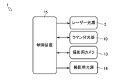
- the control device 15 controls the Raman spectroscopic measurement device 1.
- the control device 15 may actually be configured such that a CPU, ROM, RAM, HDD, or the like is connected by a bus, or may be configured by a one-chip LSI or the like.
- the control device 15 stores various programs and data for controlling the Raman spectroscopic measurement device 1.
- the control device 15 is connected to the laser light source 2 and the illumination light source 14 for photographing, and can control the laser light source 2 and the illumination light source 14 for photographing.
- the control device 15 is connected to the Raman spectrometer 10 and can control the Raman spectrometer 10. In addition, the control device 15 can acquire the spectroscopic measurement result from the Raman spectrometer 10.
- the control device 15 is connected to the photographing camera 13 and can control the photographing camera 13. Further, the control device 15 can acquire an image taken from the photographing camera 13.
- the Raman spectroscopic measurement apparatus 1 configured in this way has the laser light L1 applied to a plurality of locations of the sample S at a time in a state where the laser light L1 emitted from the laser light source 2 is divided into a plurality of optical paths by the microlens array 4. Is irradiated.
- the Raman spectroscopic measurement apparatus 1 irradiates the sample S with the photographic illumination light L ⁇ b> 3 from the photographic illumination light source 14 via the total reflection mirror 6.
- the Raman scattered light L2 generated from the sample S by the irradiation of the laser light L1 is incident on the Raman spectroscope 10 by the dichroic mirror 7.
- the Raman spectroscopic measurement apparatus 1 spectroscopically measures the Raman scattered light L2 with the Raman spectroscope 10.
- the imaging illumination light L3 irradiated to the sample S from the imaging illumination light source 14 becomes light reflected from the sample S (hereinafter simply referred to as “reflected light L4”) when reaching the sample S.
- the reflected light L 4 from the sample S is reflected by the total reflection mirror 6 and the half mirror 11 and enters the photographing camera 13.
- the Raman spectroscopic measurement apparatus 1 obtains an image in the form of the sample S and images of a plurality of irradiation points of the laser light L1 from the reflected light L4 by the photographing camera 13.
- the Raman spectroscopic measurement apparatus 1 specifies the structure of the sample S from the spectroscopic measurement result, the image in the form of the sample S, and the images of the plurality of irradiation points of the laser light L1 by the control device 15.
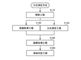
- an irradiation process in which the sample S is irradiated with the imaging illumination light L3 and the laser light L1 that is the spectral illumination light is irradiated to a plurality of locations, and a process K120.
- an image acquisition process for acquiring an image V composed of an image in the form of the sample S and images of a plurality of irradiation points of the laser light L1 and as a process K130, Raman light excited from the plurality of irradiation points by the laser light L1.
- an image of the same structure is formed from the hue, brightness, saturation, and luminance that are image information as the spectroscopic measurement step for spectroscopic measurement and the step K140.
- the spectroscopic measurement method is performed from step K110 to step K150 in order.
- the Raman spectroscopic measurement apparatus 1 uses the laser light L1 oscillated by the laser light source 2 as the laser light L1 irradiation process.
- the light enters the first lens 3.
- the laser light L1 is emitted from the first lens 3 for laser light as parallel light from a point light source at infinity.
- the laser light L1 emitted from the first laser light lens 3 is incident on the microlens array 4.
- the laser light L1 is divided into a plurality of optical paths and emitted from the microlens array 4.
- the laser light L1 divided into a plurality of optical paths emitted from the microlens array 4 is incident on the second lens 5 for laser light.
- the laser light L1 composed of a plurality of optical paths is emitted from the second lens 5 for laser light so as to be focused at the position of the pinhole 6a of the total reflection mirror 6.
- the laser light L1 emitted from the second lens 5 for laser light passes through the pinhole 6a without interfering with the total reflection mirror 6.
- the laser beam L 1 that has passed through the total reflection mirror 6 is incident on the dichroic mirror 7.
- the laser light L1 which is short wavelength light is transmitted without being reflected by the dichroic mirror 7 which reflects long wavelength light.
- the laser beam L 1 that has passed through the dichroic mirror 7 is incident on the imaging lens 8.
- the laser light L1 is emitted from the imaging lens 8 so as to be condensed on the surface of the sample S for each optical path.
- the laser beam L1 is irradiated to a plurality of locations on the sample S. Thereby, the laser beam L1 generates Raman scattered light L2 (see FIG. 6) having a spectrum corresponding to the molecular structure from the irradiated portion of the sample S.
- the Raman spectroscopic measurement apparatus 1 is focused by the second laser light lens 5 and passes through the pinhole 6a of the total reflection mirror 6 without interference even when the laser light L1 is divided into a plurality of optical paths. It is configured. Further, the Raman spectroscopic measurement apparatus 1 is configured such that a part of the laser light L1 is not reflected by the dichroic mirror 7 that reflects the Raman scattered light L2. That is, in the Raman spectroscopic measurement apparatus 1, the laser beam L1 is not shielded by the total reflection mirror 6 and the dichroic mirror 7 arranged on the optical axis of the laser beam L1. Thereby, it is possible to suppress a loss that occurs before the laser light L1 from the light source reaches the sample S.
- step K110 the Raman spectroscopic measurement device 1 shoots the illumination light L3 for photographing from the illumination light source 14 for photographing toward the half mirror 11 as an irradiation step of the illumination light L3 for photographing. Is emitted. A part of the photographing illumination light L3 passes through the half mirror 11 and is emitted toward the total reflection mirror 6. The photographing illumination light L3 emitted toward the total reflection mirror 6 is reflected by a portion other than the pinhole 6a of the total reflection mirror 6 so as to coincide with the optical axis of the laser light L1.
- the photographing illumination light L3 reflected by the total reflection mirror 6 is incident on a dichroic mirror 7 that reflects long wavelength light along the optical axis of the laser light L1. Only the light in the short wavelength region of the photographic illumination light L ⁇ b> 3 passes through the dichroic mirror 7 and enters the imaging lens 8. The light in the short wavelength region of the illuminating illumination light L3 transmitted through the dichroic mirror 7 is emitted from the imaging lens 8 so as to be condensed on the surface of the sample S. Light in the short wavelength region of the imaging illumination light L3 is irradiated on the sample S and reflected by the surface of the sample S.
- the Raman spectroscopic measurement apparatus 1 uses the reflected light L4 from the sample S of the laser light L1 and the light in the short wavelength region of the imaging illumination light L3 as the image acquisition process. From the sample S side. (Hereinafter, when light enters the imaging lens 8 from the sample S side, it is simply referred to as “sample-side lens 8”). That is, the reflected light L 4 from the sample S is incident on the sample side lens 8. The reflected light L4 from the sample S is emitted from the sample side lens 8 as light from a point light source at infinity. The reflected light L4 from the sample S emitted from the sample side lens 8 is incident on the dichroic mirror 7 that reflects long wavelength light.
- the reflected light L4 from the sample S which is light in the short wavelength region, passes through the dichroic mirror 7. That is, the reflected light L 4 from the sample S is emitted toward the total reflection mirror 6.
- the reflected light L4 from the sample S emitted toward the total reflection mirror 6 is reflected toward the half mirror 11 by the total reflection mirror 6. A part of the reflected light L4 from the sample S is reflected by the half mirror 11 toward the photographing camera 13.
- the photographing camera 13 (see FIG. 4) generates an image V from the reflected light L4.
- an image in the form of the sample S and images of a plurality of irradiation points s1, s2, s3,... S16 of the laser light L1 are displayed at the same time.
- a portion of the first structure Sa and a portion of the second structure Sb (light ink portion) of the sample S are displayed.
- the control device 15 acquires the image V from the photographing camera 13.
- the Raman spectrometer 1 can simultaneously confirm the surface state of the sample S and the Raman spectrum of the Raman scattered light L2 at a plurality of irradiation points s1, s2, s3,... S16 (see FIG. 3). ).
- the Raman spectroscopic measurement apparatus 1 is configured such that the reflected light L4 from the sample S is not reflected by the dichroic mirror 7.
- the reflected light L ⁇ b> 4 from the sample S is reflected by a portion other than the pinhole 6 a of the total reflection mirror 6. That is, in the Raman spectroscopic measurement apparatus 1, the reflected light L4 from the sample S is hardly inhibited by the total reflection mirror 6 and the dichroic mirror 7 arranged on the optical axis of the laser light L1. Thereby, it is possible to suppress a loss that occurs before the reflected light L4 from the sample S reaches the camera.
- the illumination light L3 for imaging from the illumination light source for imaging 14 and the reflected light L4 from the sample S are configured to have the same optical axis by the half mirror 11, but this is not limitative. Instead of this, a configuration in which the shooting camera 13 and the shooting illumination light source 14 are integrally configured and the half mirror 11 is omitted may be employed.
- the Raman spectroscopic measurement apparatus 1 performs, as a spectroscopic measurement step, long-wavelength Raman scattered light L ⁇ b> 2 generated from the irradiated part of the sample S, Incident.
- the Raman scattered light L2 composed of a plurality of optical paths enters and exits the sample side lens 8.
- the Raman scattered light L2 emitted from the sample side lens 8 is incident on the dichroic mirror 7.
- the long-wavelength Raman scattered light L2 is reflected by the dichroic mirror 7 that reflects the long-wavelength light. That is, the Raman scattered light L ⁇ b> 2 composed of a plurality of optical paths is incident on the Raman imaging lens 9 by the dichroic mirror 7.
- the Raman scattered light L2 is emitted from the Raman imaging lens 9 so as to form an image on the incident surface of the Raman spectrometer 10.
- the Raman spectroscopic measurement apparatus 1 uses the Raman imaging light 9 to multi-scatter the Raman scattered light L2 from the irradiation points s1, s2, s3,... S16 of the laser light L1.
- Light is received by a two-dimensional array portion which is one end of the optical fiber 16.
- the Raman spectroscopic measurement device 1 converts the two-dimensional array received at one end of the multi-optical fiber 16 into a one-dimensional array, and emits it from the other end of the multi-optical fiber 16 to the diffraction grating.
- the emitted Raman scattered light L2 converted into a one-dimensional array is guided to the area sensor via the diffraction grating. Thereby, the Raman spectroscopic measurement apparatus 1 can measure the Raman spectroscopic spectrum of the plurality of irradiation points s1, s2, s3,.
- the Raman spectroscopic measurement apparatus 1 reflects the Raman scattered light L2 including a plurality of optical paths generated by the laser light L1 divided into the plurality of optical paths toward the Raman spectroscope 10 by the dichroic mirror 7.
- the Raman scattered light L ⁇ b> 2 composed of a plurality of generated optical paths can be incident on the Raman spectrometer 10.
- the Raman spectroscopic measurement apparatus 1 acquires the image V from the reflected light L4 and the spectroscopic measurement process in which the sample S is irradiated with the laser light L1 divided into a plurality of optical paths and the Raman scattered light L2 from the sample is measured.
- the image acquisition process to be performed can be performed simultaneously.
- the control device 15 of the Raman spectroscopic measurement apparatus 1 constructs an image in the image of the sample S in the acquired image V as an image processing process.
- a range of the same structure is specified based on image information assigned to each unit pixel (hereinafter simply referred to as “pixel”) which is the smallest unit.
- pixel image information assigned to each unit pixel
- the control device 15 determines that the adjacent pixels are It is determined that images of different structures are formed.
- the control device 15 sets a boundary based on the determination result based on the image information between adjacent pixels in all the pixels, and extracts an aggregate of pixels constituting an image of the same structure as an image region ( FIG. 8 (a)). Similarly, the control device 15 extracts a group of pixels constituting an image of another identical structure as an image area from the image of the sample S in the image V, and is an independent closed area.
- the image is divided into a first image area Ar1, a second image area Ar2, and a third image area Ar3 (FIG. 8B).
- the boundary of the image area is determined based on whether or not the image information between adjacent pixels exceeds a specified value.
- the present invention is not limited to this, and the same structure is used using the image information. It suffices if an image area representing the body can be extracted.
- step K150 the controller 15 of the Raman spectroscopic measurement apparatus 1 performs the region determination step in which the first image that is a closed region of the same structure in the image V is displayed.
- the spectral measurement results of the plurality of irradiation points s1, s2, s3,... S16 of the laser light L1 are superimposed on the image in the form of the sample S divided into the region Ar1, the second image region Ar2, and the third image region Ar3.
- the control device 15 indicates the same structure among the spectroscopic measurement results of the plurality of irradiation points s1, s2, s3, s4, s5, and s6 of the laser light L1 in the first image region Ar1 having the same structure.
- the ratio of the number of irradiation points that is the spectroscopic measurement result is equal to or greater than a predetermined value. If the ratio is equal to or greater than the predetermined value, the structure in the first image region Ar1 is specified as the structure of the spectroscopic measurement result. .
- the Raman spectroscope 10 (see FIG. 6) outputs a Raman spectrum of the Raman scattered light L2 at the irradiation points s1, s2, s3... S16 (see FIG. 7).
- the control device 15 acquires the Raman spectra of the irradiation points s 1, s 2, s 3, s 4, s 5, and s 6 from the Raman spectrometer 10.
- the waveforms and peak positions of the irradiation points s4, s5 are different from the waveforms and peak positions of the irradiation points s1, s2, s3, and s6.
- the control device 15 defines the first image area Ar1 as the first structure Sa. To be identified. Similarly, among the five measurement points s7, s8, s9, s10, and s11 in the second image area Ar2, the four points of the irradiation points s7, s8, s10, and s11 have the same second structure Sb. In the case of the spectroscopic measurement result shown in FIG.
- the control device 15 specifies the second image region Ar2 as the second structure Sb.
- the three measurement points of the irradiation points s14, s15, and s16 indicate the same first structure Sa.
- the control device 15 specifies the third image region Ar3 as the first structure Sa because the ratio of the number of irradiation points, which is the spectroscopic measurement result indicating the first structure Sa, is less than the predetermined value 65% in the present embodiment. Can not. Accordingly, the Raman spectroscopic measurement apparatus 1 performs again the irradiation process of the laser beam L1, the image acquisition process, the spectroscopic measurement process, the image processing process, and the area determination process for the third image area Ar3. The control device 15 converts the structure of the first image region Ar1, the second image region Ar2, and the third image region Ar3 divided into the closed regions of the same structure along the above steps into the ratio of the spectroscopic measurement result. Judgment based on.
- the Raman spectroscopic measurement apparatus 1 acquires an image V including an image in the form of the sample S and images of the plurality of irradiation points s1, s2, s3,... S16 of the laser light L1. A plurality of irradiation points s1, s2, s3,... S16 of the laser light L1 on the sample S can be observed. Further, the Raman spectroscopic measurement apparatus 1 is configured to set each of the first image area Ar1, the second image area Ar2, and the third image area Ar3 that are set as ranges constituted by the same structure based on the image information.
- the entire structure is specified. Thereby, the structure which comprises 1st image area
- the measurement time can be shortened compared with the case where the first image area Ar1, the second image area Ar2, and the third image area Ar3 are measured with a scanning microscopic Raman spectroscopic apparatus.
- the Raman spectroscopic measurement apparatus 1 which is an embodiment of the Raman spectroscopic measurement apparatus is configured to irradiate the sample S with the laser light L1 divided into a plurality of optical paths, but is not limited thereto. Further, on the basis of the optical path of the laser light L1, a photographing optical path is provided at a position on the laser light source 2 side, and an optical path of Raman scattered light L2 is provided at a position on the sample S side.
- the present invention is not limited to this. Absent.
- the Raman spectroscopic measurement device 1 has a configuration in which an optical path for photographing is secured using the total reflection mirror 6 and an optical path of the Raman scattered light L2 is secured using the dichroic mirror 7 with the optical path of the laser light L1 as a reference. Good.
- the present invention is applicable to a spectroscopic measurement method and a spectroscopic measurement device, particularly a Raman spectroscopic measurement method and a Raman spectroscopic device.
Landscapes
- Physics & Mathematics (AREA)
- Spectroscopy & Molecular Physics (AREA)
- General Physics & Mathematics (AREA)
- Health & Medical Sciences (AREA)
- Chemical & Material Sciences (AREA)
- Analytical Chemistry (AREA)
- Pathology (AREA)
- Life Sciences & Earth Sciences (AREA)
- Biochemistry (AREA)
- General Health & Medical Sciences (AREA)
- Immunology (AREA)
- Engineering & Computer Science (AREA)
- Optics & Photonics (AREA)
- Mathematical Physics (AREA)
- Theoretical Computer Science (AREA)
- Nuclear Medicine, Radiotherapy & Molecular Imaging (AREA)
- Investigating, Analyzing Materials By Fluorescence Or Luminescence (AREA)
- Investigating Or Analysing Materials By Optical Means (AREA)
- Microscoopes, Condenser (AREA)
- Spectrometry And Color Measurement (AREA)
Abstract
所定の領域を構成する構造体の特定を短時間で精度よく正確に行うことができる分光測定方法および分光測定装置を提供する。試料Sに撮影用照明光L3を照射し、分光用照明光であるレーザー光L1を複数の箇所に照射する照射工程と、試料Sの形態とレーザー光L1の複数の照射点とからなる画像Vを取得する画像取得工程と、レーザー光L1によって励起される光を分光測定する分光測定工程と、試料Sの画像Vにおいて、画像情報から同一の構造体で構成される画像領域である第1画像領域Ar1等を抽出し、抽出した各画像領域を閉領域として分割する画像処理工程と、分光測定結果を各画像領域に分割された試料Sの画像におけるレーザー光L1の照射点に重ね合わせ、各画像領域内におけるレーザー光L1の複数の照射点の分光測定結果に基づいて各画像領域の構造体を特定する領域判定工程と、から構成される。
Description
本発明は、分光測定方法および分光測定装置、特にラマン分光測定方法およびラマン分光装置に関する。
従来、レーザー光が物質に照射されると発生するラマン散乱光を利用して、物質の構成を特定するラマン分光測定装置が知られている。ラマン散乱光は、レーザー光の照射点の物質の分子構造に応じてそれぞれ固有のスペクトルで発生する。このため、ラマン分光測定装置は、ラマン散乱光を発生させるレーザー光等の光源、ラマン分光器(検出器)に加えてレーザー光の照射点等を確認するためのカメラと撮影用照明光源を備えたものがある。例えば特許文献1の如くである。
特許文献1に記載の顕微ラマン分光装置は、カメラのレンズの光軸上にレーザー光用のハーフミラー(半透明鏡)と撮影用照明光源用のハーフミラーとが配置されている。つまり、ハーフミラーにより反射されたレーザー光の一部と別のハーフミラーにより反射された撮影用照明光の一部をカメラとレンズを結ぶ光軸上に一致させている。これにより、特許文献1に記載の顕微ラマン分光装置は、レーザー光の照射点の撮影をより正確に行うことができる。
特許文献1に記載の技術は、試料の任意の位置に照射されたレーザー光の照射点を撮影するとともに分光測定によりその照射点における試料の構造体を特定するものである。このため、照射点に異物等が付着していた場合、あるいは、分光測定に基づく構造体識別の正答率が100%でない限り、顕微ラマン分光装置では、照射点の構造体と異なる構造体を示す分光測定結果が得られる可能性がある。しかし、顕微ラマン分光装置は、単独の照射点の分光測定結果に基づく構造体の判定が正しいか否かを判断することができない。また、顕微ラマン分光装置は、走査型の分光測定によって二次元の面状に配置した複数の照射点における分光測定結果から構造体を特定することが可能である。しかし、走査型の顕微ラマン分光装置は、単独の照射点の場合と同様に分光測定結果に基づく判定が正しいか否かを判断することができない。さらに、走査型の顕微ラマン分光装置では、測定が長時間になることに加えて、照射点以外の部分の構造体を周囲の分光測定結果から推測するしかなく、試料において同一の構造体から構成されている領域を正確に特定できない。
本発明の目的は、所定の領域を構成する構造体の特定を短時間で精度よく正確に行うことができる分光測定方法および分光測定装置の提供を目的とする。
本発明の解決しようとする課題は以上の如くであり、次にこの課題を解決するための手段を説明する。
即ち、試料に撮影用照明光と分光用照明光とを照射し、撮影用カメラによって前記試料の形態と前記分光用照明光の照射点の画像を取得しつつ、前記分光用照明光によって励起される光を分光測定する分光測定方法であって、前記試料に前記撮影用照明光を照射し、前記分光用照明光を複数の箇所に照射する照射工程と、前記試料の形態の画像と前記分光用照明光の複数の照射点の画像とを取得する画像取得工程と、前記分光用照明光によって複数の照射点から励起される光をそれぞれ分光測定する分光測定工程と、取得した前記試料の形態の画像において、画像情報から同一の構造体で構成される画像領域を抽出し、抽出した各画像領域を閉領域として分割する画像処理工程と、前記分光用照明光の複数の照射点毎の分光測定結果を前記各画像領域に分割された前記試料の形態の画像における前記分光用照明光の複数の照射点に重ね合わせ、前記各画像領域内における前記分光用照明光の複数の照射点の分光測定結果に基づいて前記各画像領域の構造体を特定する領域判定工程と、から構成される。
分光測定方法は、前記領域判定工程において、一つの前記画像領域内における前記分光用照明光の複数の照射点に対する同一の構造体を示す分光測定結果を有する分光用照明光の照射点の数の割合が所定値以上の場合、その前記画像領域の構造体をその分光測定結果の構造体として特定するものである。
分光測定方法は、前記照射工程において、前記分光用照明光が照明光分割手段によって複数の分光用照明光に分割されて前記試料に同時に照射され、前記画像取得工程と前記分光測定工程とが同時に実施されるものである。
分光測定方法は、前記画像処理工程において、前記画像情報が、色相、明度、彩度、輝度のうち少なくとも一つの情報から構成されているものである。
前記分光測定方法を実施する分光測定装置であって、所定波長の分光用照明光源と、分光器と、撮影用カメラと、撮影用照明光源と、ピンホールが形成されている全反射ミラーと、前記所定波長の分光用照明光とそれよりも短い波長の光のみを透過させるダイクロイックミラーと、を備え、前記全反射ミラーと前記ダイクロイックミラーとが前記分光用照明光の光軸上に配置されており、前記分光用照明光源からの分光用照明光が、前記全反射ミラーのピンホールを通過して前記試料に照射され、前記試料に照射された分光用照明光によって励起される光が前記ダイクロイックミラーに反射されて前記分光器に入射され、前記撮影用照明光源からの撮影用照明光が、前記全反射ミラーに反射されて前記分光用照明光の光軸に前記撮影用照明光の光軸を一致させた状態で前記試料に照射され、前記試料から反射した撮影用照明光が、その光軸を前記分光用照明光の光軸に一致させた状態で前記全反射ミラーに反射されて前記撮影用カメラに入射されるものである。
本発明は、以下に示すような効果を奏する。
分光測定方法においては、一つの構造体から構成される範囲として設定される画像領域内における複数箇所の分光測定結果を画像領域に適用することで、画像領域内の分光用照明光が照射されていない部分を含む画像領域全体の構造体が特定される。これにより所定の領域を構成する構造体の特定を短時間で精度よく行うことができる。また、測定密度を高くして画像領域内を測定する場合よりも測定時間を短くすることができる。
分光測定方法においては、画像領域内の各分光測定結果の全体から一つの結果を導きだして判定するので、測定結果に誤判定が含まれていても画像領域全体の構造が正確に特定される。これにより、所定の領域を構成する構造体の特定を正確に行うことができる。
分光測定方法においては、一度に画像領域内の複数の箇所に分光用照明光が照射される。これにより、所定の領域を構成する構造体の特定を精度よく行うことができる。また、測定密度を高くして画像領域内を測定する場合よりも測定時間を短くすることができる。
分光測定方法においては、試料の形態の画像がその形態に応じて適切に画像領域に分割される。これにより、所定の領域を構成する構造体の特定を精度よく行うことができる。
分光測定装置においては、複数の分光用照明光が光学系の影響を受けることなく出力を維持した状態で一度に照射され、分光測定結果を画像領域に適用することで画像領域内の分光用照明光が照射されていない部分を含む画像領域全体の構造体が特定される。これにより、所定の領域を構成する構造体の特定を精度よく正確に行うことができる。また、測定密度を高くして画像領域内を測定する場合よりも測定時間を短くすることができる。
初めに、図1と図2とを用いて、分光測定方法を実施する分光測定装置であるラマン分光測定装置の一実施形態であるラマン分光測定装置1について説明する。なお、本実施形態において、分光測定装置としてラマン分光測定装置1について具体的に説明するがこれに限定するものではなく、蛍光分光測定装置等の様々な分光用照明光を用いる分光測定装置においても同様である。
図1に示すように、ラマン分光測定装置1は、試料Sに分光用照明光としてレーザー光L1を照射することで試料Sから発生するラマン散乱光L2を検出するものである。ラマン分光測定装置1は、レーザー光源2、レーザー光用第1レンズ3、レーザー光用第2レンズ5、全反射ミラー6、ダイクロイックミラー7、結像レンズ8、ラマン用結像レンズ9、ラマン分光器10、ハーフミラー11、撮影用結像レンズ12、撮影用カメラ13、撮影用照明光源14および制御装置15を具備している。
レーザー光源2は、ラマン散乱光L2を発生させるための分光用照明光であるレーザー光L1を発振するものである。レーザー光源2は、所定波長のレーザー光L1を発振する。本実施形態において、レーザー光源2は、短波長(400nmから600nm)レーザー光L1を発振するものとする。なお、本実施形態においてレーザー光源2の媒質は、短波長のレーザー光L1を発振するものであればよい。
レーザー光用第1レンズ3は、入射された光を平行光にするレンズである。レーザー光用第1レンズ3は、レーザー光源2からのレーザー光L1が入射されるように、レーザー光L1の光軸上にレーザー光源2と隣り合うように配置されている。
照明光分割手段であるマイクロレンズアレイ4は、入射されたレーザー光L1を複数のレーザー光L1に分割するものである。マイクロレンズアレイ4は、マイクロレンズが格子状に形成されている。マイクロレンズアレイ4は、レーザー光用第1レンズ3からのレーザー光L1が入射されるように、レーザー光L1の光軸上にレーザー光用第1レンズ3と隣り合うように配置されている。マイクロレンズアレイ4は、入射されるレーザー光L1を複数の光路に分割してマイクロレンズアレイ4から出射するように構成されている。なお、本実施形態において、照明光分割手段がマイクロレンズアレイ4から構成されているがこれに限定するものではなく、回折光学素子やマルチ光ファイバなどの光路分割光学系であればよい。
レーザー光用第2レンズ5は、入射されたレーザー光L1を集束させるレンズである。レーザー光用第2レンズ5は、マイクロレンズアレイ4からのレーザー光L1が入射されるように、レーザー光L1の光軸上にマイクロレンズアレイ4と隣り合うように配置されている。レーザー光用第2レンズ5は、入射される複数の光路に分割されたレーザー光L1が所定の集束位置Pを通過するようにレーザー光用第2レンズ5から出射するように構成されている。
全反射ミラー6は、中央にピンホール6aが形成されている。全反射ミラー6は、レーザー光用第2レンズ5からのレーザー光L1が入射されるように、レーザー光L1の光軸上にレーザー光用第2レンズ5と隣り合うように配置されている。また、全反射ミラー6は、レーザー光用第2レンズ5を透過した複数の光路に分割されたレーザー光L1の集束位置Pとピンホール6aの位置とが一致するように配置されている。つまり、全反射ミラー6は、複数の光路に分割されたレーザー光L1が全反射ミラー6のピンホール6aの位置で集束して全反射ミラー6と干渉することなくピンホール6aを通過するように構成されている。
本実施形態において、全反射ミラー6は、レーザー光L1の光軸に対して45度の傾斜角度になるように配置されている。全反射ミラー6は、レーザー光L1の光軸に対して90度の方向から全反射ミラー6に向かって出射された光線をレーザー光L1の光軸と一致するように全反射ミラー6のピンホール6a以外の部分で反射させるように構成されている。一方、全反射ミラー6は、レーザー光L1の光軸方向から全反射ミラー6に向かって出射された光線をレーザー光L1の光軸に対して90度の方向に全反射ミラー6のピンホール6a以外の部分で反射するように構成されている。なお、本実施形態において、全反射ミラー6、ダイクロイックミラー7およびハーフミラー11の配置角度は、それぞれ45度に限定されるものでは無く、機器構成上の適する配置にすればよい。
波長選択ハーフミラーであるダイクロイックミラー7は、所定の波長の光のみを選択的に透過させるものである。本実施形態において、ダイクロイックミラー7は、レーザー光L1の波長とそれよりも短い波長の光のみを選択的に透過するように構成されている。ダイクロイックミラー7は、全反射ミラー6のピンホール6aを通過したレーザー光L1が入射するように、レーザー光L1の光軸上に全反射ミラー6と隣り合うように配置されている。また、ダイクロイックミラー7は、レーザー光L1の光軸に対して45度の傾斜角度になるように配置されている。つまり、ダイクロイックミラー7は、長波長であるラマン散乱光L2をレーザー光L1の光軸に対して90度の方向に反射するように構成されている。
結像レンズ8は、レーザー光L1を集光するレンズである。結像レンズ8は、ダイクロイックミラー7からのレーザー光L1が入射するように、レーザー光L1の光軸上にダイクロイックミラー7と隣り合うように配置されている。また、結像レンズ8は、試料Sに照射されるレーザー光L1の照射点から発生するラマン散乱光L2が結像レンズ8の試料S側から入射される。
ラマン用結像レンズ9は、ラマン散乱光L2を集光してラマン分光器10に入射させるレンズである。ラマン用結像レンズ9は、ダイクロイックミラー7からの光が入射するように、レーザー光L1の光軸に対して90度の位置にダイクロイックミラー7と隣り合うようにして配置されている。つまり、ラマン用結像レンズ9は、ダイクロイックミラー7によってレーザー光L1の光軸に対して90度の方向に反射されたラマン散乱光L2が入射するように配置されている。
ラマン分光器10は、ラマン散乱光L2からラマンスペクトルを検出するものである。ラマン分光器10は、例えばマルチ光ファイバ、回折格子、エリアセンサとレンズ、ミラー等から構成されている。ラマン分光器10は、ラマン用結像レンズ9からのラマン散乱光L2が入射するように、レーザー光L1の光軸に対して90度の位置にラマン用結像レンズ9と隣り合うように配置されている。さらに本実施形態において、不要な短波長光をカットするために、ダイクロイックミラー7とラマン分光器10の間にロングパスフィルタ10aを入れる構成をとることが好ましい。
ハーフミラー11は、光の一部を透過させて一部を反射させるものである。ハーフミラー11は、全反射ミラー6で反射される光が入射するように、レーザー光L1の光軸に対して90度の位置に全反射ミラー6と隣り合うように配置されている。また、ハーフミラー11は、レーザー光L1の光軸に対して45度の傾斜角度になるように配置されている。つまり、ハーフミラー11は、レーザー光L1の光軸に対して平行な方向に光を反射させる。
撮影用結像レンズ12は、撮影用カメラ13に集光するレンズである。撮影用結像レンズ12は、ハーフミラー11によって反射された光が入射するように、レーザー光L1の光軸に対して平行な位置にハーフミラー11と隣り合うように配置されている。撮影用結像レンズ12は、撮影用カメラ13に集光するように構成されている。
撮影用カメラ13は、試料Sの形態の画像とレーザー光L1の照射点の画像とを撮影するものである。撮影用カメラ13は、CMOSカメラ等から構成されている。撮影用カメラ13は、撮影用結像レンズ12からの光が入射するように、レーザー光L1の光軸に対して平行な位置に撮影用結像レンズ12と隣り合うように配置されている。撮影用カメラ13によって、レーザー光L1の照射点および試料Sの表面状態を視認することができる。
撮影用照明光源14は、撮影用照明光L3を発生させるものである。撮影用照明光源14は、全反射ミラー6に撮影用照明光L3を照射するように、レーザー光L1の光軸に対して90度の位置にハーフミラー11と隣り合うように配置されている。撮影用照明光源14は、撮影用照明光用レンズ14a、ハーフミラー11を介して全反射ミラー6に向かって撮影用照明光L3を出射するように構成されている。
図2に示すように、制御装置15は、ラマン分光測定装置1を制御するものである。制御装置15は、実体的には、CPU、ROM、RAM、HDD等がバスで接続される構成であってもよく、あるいはワンチップのLSI等からなる構成であってもよい。制御装置15は、ラマン分光測定装置1を制御するために種々のプログラムやデータが格納されている。
制御装置15は、レーザー光源2と撮影用照明光源14とに接続され、レーザー光源2と撮影用照明光源14とを制御することができる。
制御装置15は、ラマン分光器10に接続され、ラマン分光器10を制御することができる。また、制御装置15は、ラマン分光器10から分光測定結果を取得することができる。
制御装置15は、撮影用カメラ13に接続され、撮影用カメラ13を制御することができる。また、制御装置15は、撮影用カメラ13から撮影した画像を取得することができる。
このように構成されるラマン分光測定装置1は、レーザー光源2から照射されるレーザー光L1がマイクロレンズアレイ4によって複数の光路に分割された状態で一度に試料Sの複数の箇所にレーザー光L1が照射される。合わせて、ラマン分光測定装置1は、撮影用照明光源14からの撮影用照明光L3が全反射ミラー6を介して試料Sに照射される。レーザー光L1の照射により試料Sから発生したラマン散乱光L2は、ダイクロイックミラー7によってラマン分光器10に入射される。ラマン分光測定装置1は、ラマン分光器10によってラマン散乱光L2を分光測定する。一方、撮影用照明光源14から試料Sに照射された撮影用照明光L3は、試料Sに到達すると試料Sからの反射した光(以下、単に「反射光L4」と記す)になる。試料Sからの反射光L4は、全反射ミラー6およびハーフミラー11によって反射されて撮影用カメラ13に入射される。ラマン分光測定装置1は、撮影用カメラ13によって、反射光L4から試料Sの形態の画像とレーザー光L1の複数の照射点の画像とを得る。ラマン分光測定装置1は、制御装置15によって、分光測定結果と試料Sの形態の画像とレーザー光L1の複数の照射点の画像とから試料Sの構造体を特定する。
次に、図3から図9を用いて、ラマン分光測定装置1における分光測定方法について説明する。
図3に示すように、分光測定方法は、工程K110として、試料Sに撮影用照明光L3を照射し、分光用照明光であるレーザー光L1を複数の箇所に照射する照射工程と、工程K120として、試料Sの形態の画像とレーザー光L1の複数の照射点の画像とからなる画像Vを取得する画像取得工程と、工程K130として、レーザー光L1によって複数の照射点から励起されるラマン光をそれぞれ分光測定する分光測定工程と、工程K140として、取得した画像Vの試料Sの形態の画像において、画像情報である色相、明度、彩度、輝度から同一の構造体の画像を構成している画素の集合体を画像領域として抽出し、抽出した各画像領域を閉領域として分割する画像処理工程と、工程K150として、レーザー光L1の複数の照射点毎の分光測定結果を画像Vにおけるレーザー光L1の複数の照射点の画像に重ね合わせ、分光測定結果に基づいて各画像領域の構造体を特定する領域判定工程と、から構成されている。分光測定方法は、工程K110から順に工程K150まで実施される。
図4に示すように、工程K110(図3参照)において、ラマン分光測定装置1は、レーザー光L1の照射工程として、レーザー光源2で発振されたレーザー光L1(薄墨部分参照)がレーザー光用第1レンズ3に入射される。レーザー光L1は、無限遠にある点光源からの平行光としてレーザー光用第1レンズ3から出射される。レーザー光用第1レンズ3から出射されたレーザー光L1は、マイクロレンズアレイ4に入射される。レーザー光L1は、複数の光路に分割されてマイクロレンズアレイ4から出射される。マイクロレンズアレイ4から出射された複数の光路に分割されたレーザー光L1は、レーザー光用第2レンズ5に入射される。
複数の光路からなるレーザー光L1は、全反射ミラー6のピンホール6aの位置で集束するようにレーザー光用第2レンズ5から出射される。レーザー光用第2レンズ5から出射されたレーザー光L1は、全反射ミラー6と干渉することなくピンホール6aを通過する。全反射ミラー6を通過したレーザー光L1は、ダイクロイックミラー7に入射される。短波長光であるレーザー光L1は、長波長光を反射するダイクロイックミラー7に反射されることなく透過する。ダイクロイックミラー7を透過したレーザー光L1は、結像レンズ8に入射される。レーザー光L1は、光路毎に試料Sの表面に集光するように結像レンズ8から出射される。レーザー光L1は、試料Sの複数の箇所に照射される。これにより、レーザー光L1は、試料Sの照射箇所からその分子構造に応じたスペクトルを有するラマン散乱光L2(図6参照)を発生させる。
このように、ラマン分光測定装置1は、レーザー光L1が複数の光路に分割されてもレーザー光用第2レンズ5によって集束されて全反射ミラー6のピンホール6aを干渉することなく通過するように構成されている。また、ラマン分光測定装置1は、ラマン散乱光L2を反射するダイクロイックミラー7によってレーザー光L1の一部が反射されないように構成されている。つまり、ラマン分光測定装置1においては、レーザー光L1の光軸上に配置された全反射ミラー6とダイクロイックミラー7とによってレーザー光L1が遮蔽されない。これにより、光源からのレーザー光L1が試料Sに至るまでの間に生じる損失を抑制することができる。
図5に示すように、工程K110(図3参照)において、ラマン分光測定装置1は、撮影用照明光L3の照射工程として、ハーフミラー11に向かって撮影用照明光源14から撮影用照明光L3が出射される。撮影用照明光L3は、その一部がハーフミラー11を透過して全反射ミラー6に向かって出射される。全反射ミラー6に向かって出射された撮影用照明光L3は、レーザー光L1の光軸と一致するように全反射ミラー6のピンホール6a以外の部分で反射される。全反射ミラー6で反射された撮影用照明光L3は、レーザー光L1の光軸に沿って長波長光を反射するダイクロイックミラー7に入射される。撮影用照明光L3は、短波長領域の光のみがダイクロイックミラー7を透過して結像レンズ8に入射される。ダイクロイックミラー7を透過した撮影用照明光L3の短波長領域の光は、試料Sの表面に集光するように結像レンズ8から出射される。撮影用照明光L3の短波長領域の光が試料Sに照射されるとともに試料Sの表面で反射する。
工程K120(図3参照)において、ラマン分光測定装置1は、画像取得工程として、レーザー光L1と撮影用照明光L3の短波長領域の光との試料Sからの反射光L4が結像レンズ8に試料S側から入射される。(以下、結像レンズ8に光が試料S側から入射される場合、単に「試料側レンズ8」と記す)。すなわち、試料Sからの反射光L4は、試料側レンズ8に入射される。試料Sからの反射光L4は、無限遠にある点光源からの光として試料側レンズ8から出射される。試料側レンズ8から出射された試料Sからの反射光L4は、長波長光を反射するダイクロイックミラー7に入射される。短波長領域の光である試料Sからの反射光L4は、ダイクロイックミラー7を透過する。すなわち、試料Sからの反射光L4は、全反射ミラー6に向かって出射される。全反射ミラー6に向かって出射された試料Sからの反射光L4は、全反射ミラー6によってハーフミラー11に向かって反射される。試料Sからの反射光L4は、その一部がハーフミラー11によって撮影用カメラ13に向かって反射される。
図7(a)に示すように、ラマン分光測定装置1は、撮影用カメラ13(図4参照)が反射光L4から画像Vを生成する。画像Vには、試料Sの形態の画像とレーザー光L1の複数の照射点s1・s2・s3・・・s16の画像とが同時に表示されている。さらに画像Vには、試料Sのうち第1構造体Saの部分と第2構造体Sb(薄墨部分)の部分とが表示されている。ラマン分光測定装置1は、制御装置15が撮影用カメラ13から画像Vを取得する。このように、ラマン分光測定装置1は、複数の照射点s1・s2・s3・・・s16における試料Sの表面状態とラマン散乱光L2のラマンスペクトルとを同時に確認することができる(図3参照)。
このように構成することで、ラマン分光測定装置1は、試料Sからの反射光L4がダイクロイックミラー7によって反射されないように構成されている。また、ラマン分光測定装置1は、試料Sからの反射光L4が全反射ミラー6のピンホール6a以外の部分で反射される。つまり、ラマン分光測定装置1においては、レーザー光L1の光軸上に配置された全反射ミラー6とダイクロイックミラー7とによって試料Sからの反射光L4がほとんど阻害されない。これにより、試料Sからの反射光L4がカメラに至るまでの間に生じる損失を抑制することができる。なお、本実施形態において、撮影用照明光源14からの撮影用照明光L3と試料Sからの反射光L4とはハーフミラー11によって同じ光軸になるように構成されているがこれに限定されるものではなく、撮影用カメラ13と撮影用照明光源14とを一体的に構成してハーフミラー11を省略した構成でもよい。
図6に示すように、工程K130(図3参照)において、ラマン分光測定装置1は、分光測定工程として、試料Sの照射箇所からそれぞれ発生した長波長のラマン散乱光L2が試料側レンズ8に入射される。複数の光路からなるラマン散乱光L2は、試料側レンズ8に入射され、そして出射される。試料側レンズ8から出射されたラマン散乱光L2は、ダイクロイックミラー7に入射される。長波長のラマン散乱光L2は、長波長光を反射するダイクロイックミラー7によって反射される。すなわち、複数の光路からなるラマン散乱光L2は、ダイクロイックミラー7によってラマン用結像レンズ9に入射される。ラマン散乱光L2は、ラマン分光器10の入射面に結像するようにラマン用結像レンズ9から出射される。
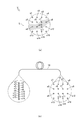
図7(b)に示すように、ラマン分光測定装置1は、レーザー光L1の照射点s1・s2・s3・・・s16からのラマン散乱光L2を、ラマン用結像レンズ9を介してマルチ光ファイバ16の一端である2次元配列部分で受光する。ラマン分光測定装置1は、マルチ光ファイバ16の一端で受光した2次元配列を1次元配列に変換してマルチ光ファイバ16の他端から回析格子に出射する。出射された1次元配列に変換されたラマン散乱光L2が回折格子を介してエリアセンサに導かれるように構成されている。これにより、ラマン分光測定装置1は、複数の照射点s1・s2・s3・・・s16のラマン分光スペクトルをラマン分光器10で測定することができる。
このように構成することで、ラマン分光測定装置1は、複数の光路に分割されたレーザー光L1によって発生する複数の光路からなるラマン散乱光L2をダイクロイックミラー7によってラマン分光器10にむかって反射させる。つまり、ラマン分光測定装置1においては、発生した複数の光路からなるラマン散乱光L2をラマン分光器10に入射させることができる。従って、ラマン分光測定装置1は、複数の光路に分割されたレーザー光L1が試料Sに照射され、試料からのラマン散乱光L2の分光測定を行う分光測定工程と反射光L4から画像Vを取得する画像取得工程とを同時に実施することができる。
図8に示すように、工程K140(図3参照)において、ラマン分光測定装置1の制御装置15は、画像処理工程として、取得した画像Vの試料Sの形態の画像において、画像を構成している最少単位である単位画素(以下、単に「画素」と記す)毎に割り当てられている画像情報に基づいて同一の構造体の範囲を特定する。制御装置15は、隣接する画素間において画像情報である色相、明度、彩度、輝度のうち、任意に選択された少なくとも一つの値が規定値を超えている場合、その隣接している画素がそれぞれ異なる構造体の画像を構成していると判定する。
制御装置15は、全ての画素において隣接する画素間での画像情報による判定結果に基づいて境界を設定し、同一の構造体の画像を構成している画素の集合体を画像領域として抽出する(図8(a))。同様にして、制御装置15は、画像Vの試料Sの形態の画像において、他の同一の構造体の画像を構成している画素の集合体を画像領域として抽出し、独立した閉領域である第1画像領域Ar1、第2画像領域Ar2および第3画像領域Ar3に分割する(図8(b))。なお、本実施形態において、隣接する画素間の画像情報が規定値を超えているか否かで画像領域の境界を判定しているがこれに限定するものではなく、画像情報を用いて同一の構造体をあらわす画像領域を抽出できればよい。
図9(a)に示すように、工程K150(図3参照)において、ラマン分光測定装置1の制御装置15は、領域判定工程として、画像Vにおいて同一の構造体の閉領域である第1画像領域Ar1、第2画像領域Ar2および第3画像領域Ar3に分割された試料Sの形態の画像にレーザー光L1の複数の照射点s1・s2・s3・・・s16の分光測定結果を重ね合わせる。制御装置15は、同一の構造体からなる第1画像領域Ar1内でのレーザー光L1の複数の照射点s1・s2・s3・s4・s5・s6の分光測定結果のうち同一の構造体を示す分光測定結果である照射点の数の割合が所定値以上であるか否かを判定し、所定値以上の場合、第1画像領域Ar1内の構造体をその分光測定結果の構造体として特定する。
ラマン分光器10(図6参照)は、照射点s1・s2・s3・・・s16(図7参照)のラマン散乱光L2のラマンスペクトルを出力する。
図9(b)に示すように、制御装置15は、ラマン分光器10から照射点s1・s2・s3・s4・s5・s6のラマンスペクトルを取得する。照射点s1・s2・s3・s4・s5・s6のうち照射点s4・s5の波形およびピーク位置が照射点s1・s2・s3・s6の波形およびピーク位置と異なる。この結果は、照射点s1・s2・s3・s6(図9(a)Ar1内の黒丸)における構造体と、照射点s4・s5(図9(a)Ar1内の白丸)における構造体とが異なることを示している。
図9(b)に示すように、制御装置15は、ラマン分光器10から照射点s1・s2・s3・s4・s5・s6のラマンスペクトルを取得する。照射点s1・s2・s3・s4・s5・s6のうち照射点s4・s5の波形およびピーク位置が照射点s1・s2・s3・s6の波形およびピーク位置と異なる。この結果は、照射点s1・s2・s3・s6(図9(a)Ar1内の黒丸)における構造体と、照射点s4・s5(図9(a)Ar1内の白丸)における構造体とが異なることを示している。
本実施形態において、第1画像領域Ar1における6点の照射点s1・s2・s3・s4・s5・s6の分光測定結果のうち照射点s1・s2・s3・s6の4点が同一の第1構造体Saを示す分光測定結果(図9(a)Ar1内の黒丸)である場合、第1画像領域Ar1内の第1構造体Saを示す分光測定結果である照射点の数の割合は、4/6≒0.67=67%になる。所定値を65%とした場合、制御装置15は第1構造体Saを示す分光測定結果である照射点の数の割合が所定値よりも大きいので、第1画像領域Ar1を第1構造体Saであると特定する。同様に、第2画像領域Ar2における5点の照射点s7・s8・s9・s10・s11の分光測定結果のうち照射点s7・s8・s10・s11の4点が同一の第2構造体Sbを示す分光測定結果(図9(a)Ar2内の黒丸)である場合、第2画像領域Ar2内の第2構造体Sbを示す分光測定結果である照射点の数の割合は4/5=0.8=80%になる。従って、制御装置15は、第2画像領域Ar2を第2構造体Sbであると特定する。
一方、第3画像領域Ar3における5点の照射点s12・s13・s14・s15・s16の分光測定結果のうち照射点s14・s15・s16の3点が同一の第1構造体Saを示す分光測定結果(図9(a)Ar3内の黒丸)である場合、第3画像領域Ar3内の第1構造体Saを示す分光測定結果である照射点の数の割合は3/5=0.6=60%になる。制御装置15は、第1構造体Saを示す分光測定結果である照射点の数の割合が本実施形態における所定値65%未満なので、第3画像領域Ar3を第1構造体Saであると特定できない。従って、ラマン分光測定装置1は、第3画像領域Ar3についてレーザー光L1の照射工程、画像取得工程、分光測定工程および画像処理工程および領域判定工程を再び実施する。制御装置15は、以上の工程に沿って同一の構造体の閉領域に分割された第1画像領域Ar1、第2画像領域Ar2、第3画像領域Ar3の構造体をその分光測定結果の割合に基づいて判定する。
このように構成することで、ラマン分光測定装置1は、試料Sの形態の画像とレーザー光L1の複数の照射点s1・s2・s3・・・s16の画像とを含む画像Vを取得して、試料Sにおけるレーザー光L1の複数の照射点s1・s2・s3・・・s16を観察することができる。さらに、ラマン分光測定装置1は、画像情報に基づいて同一の構造体から構成される範囲として設定される第1画像領域Ar1内、第2画像領域Ar2内、第3画像領域Ar3内のそれぞれの複数箇所の分光測定結果を各画像領域に重ね合わせることで第1画像領域Ar1内、第2画像領域Ar2内、第3画像領域Ar3内のレーザー光L1が照射されていない部分を含む各画像領域全体の構造体が特定される。これにより、第1画像領域Ar1、第2画像領域Ar2、第3画像領域Ar3を構成する構造体の特定を精度よく行うことができる。また、走査型の顕微ラマン分光装置で第1画像領域Ar1、第2画像領域Ar2、第3画像領域Ar3を測定する場合よりも測定時間を短くすることができる。
以上、ラマン分光測定装置の一実施形態であるラマン分光測定装置1は、複数の光路に分割したレーザー光L1を試料Sに照射する構成としているがこれに限定するものではない。また、レーザー光L1の光路を基準として、レーザー光源2側の位置に撮影用の光路が設けられ、試料S側の位置にラマン散乱光L2の光路が設けられているがこれに限定するものではない。ラマン分光測定装置1は、レーザー光L1の光路を基準として、全反射ミラー6を用いて撮影用の光路を確保し、ダイクロイックミラー7を用いてラマン散乱光L2の光路を確保する構成であればよい。上述の実施形態は、代表的な形態を示したに過ぎず、一実施形態の骨子を逸脱しない範囲で種々変形して実施することができる。さらに種々なる形態で実施し得ることは勿論のことであり、本発明の範囲は、特許請求の範囲の記載によって示され、さらに特許請求の範囲に記載の均等の意味、および範囲内のすべての変更を含む。
本発明は、分光測定方法および分光測定装置、特にラマン分光測定方法およびラマン分光装置に利用可能である。
1 分光測定装置
S 試料
V 画像
L1 レーザー光
L2 ラマン散乱光
L3 撮影用照明光
L4 反射光
Ar1 第1画像領域
Ar2 第2画像領域
Ar3 第3画像領域
Sa 第1構造体
Sb 第2構造体
S 試料
V 画像
L1 レーザー光
L2 ラマン散乱光
L3 撮影用照明光
L4 反射光
Ar1 第1画像領域
Ar2 第2画像領域
Ar3 第3画像領域
Sa 第1構造体
Sb 第2構造体
Claims (5)
- 試料に撮影用照明光と分光用照明光とを照射し、撮影用カメラによって前記試料の形態と前記分光用照明光の照射点の画像を取得しつつ、前記分光用照明光によって励起される光を分光測定する分光測定方法であって、
前記試料に前記撮影用照明光を照射し、前記分光用照明光を複数の箇所に照射する照射工程と、
前記試料の形態の画像と前記分光用照明光の複数の照射点の画像とを取得する画像取得工程と、
前記分光用照明光によって複数の照射点から励起される光をそれぞれ分光測定する分光測定工程と、
取得した前記試料の形態の画像において、画像情報から同一の構造体で構成される画像領域を抽出し、抽出した各画像領域を閉領域として分割する画像処理工程と、
前記分光用照明光の複数の照射点毎の分光測定結果を前記各画像領域に分割された前記試料の形態の画像における前記分光用照明光の複数の照射点に重ね合わせ、前記各画像領域内における前記分光用照明光の複数の照射点の分光測定結果に基づいて前記各画像領域の構造体を特定する領域判定工程と、
から構成される分光測定方法。 - 前記領域判定工程において、一つの前記画像領域内における前記分光用照明光の複数の照射点に対する同一の構造体を示す分光測定結果を有する分光用照明光の照射点の数の割合が所定値以上の場合、その前記画像領域の構造体をその分光測定結果の構造体として特定する請求項1に記載の分光測定方法。
- 前記照射工程において、前記分光用照明光が照明光分割手段によって複数の分光用照明光に分割されて前記試料に同時に照射され、前記画像取得工程と前記分光測定工程とが同時に実施される請求項1または請求項2に記載の分光測定方法。
- 前記画像処理工程において、前記画像情報が、色相、明度、彩度、輝度のうち少なくとも一つの情報から構成されている請求項1から請求項3のいずれか一項に記載の分光測定方法。
- 請求項1から請求項4のいずれか一項に記載の分光測定方法を実施する分光測定装置であって、
所定波長の分光用照明光源と、
分光器と、
撮影用カメラと、
撮影用照明光源と、
ピンホールが形成されている全反射ミラーと、
前記所定波長の分光用照明光とそれよりも短い波長の光のみを透過させるダイクロイックミラーと、を備え、
前記全反射ミラーと前記ダイクロイックミラーとが前記分光用照明光の光軸上に配置されており、
前記分光用照明光源からの分光用照明光が、前記全反射ミラーのピンホールを通過して前記試料に照射され、
前記試料に照射された分光用照明光によって励起される光が前記ダイクロイックミラーに反射されて前記分光器に入射され、
前記撮影用照明光源からの撮影用照明光が、前記全反射ミラーに反射されて前記分光用照明光の光軸に前記撮影用照明光の光軸を一致させた状態で前記試料に照射され、
前記試料から反射した撮影用照明光が、その光軸を前記分光用照明光の光軸に一致させた状態で前記全反射ミラーに反射されて前記撮影用カメラに入射される分光測定装置。
Applications Claiming Priority (2)
| Application Number | Priority Date | Filing Date | Title |
|---|---|---|---|
| JP2017000402A JP6784603B2 (ja) | 2017-01-05 | 2017-01-05 | 分光測定方法および分光測定装置 |
| JP2017-000402 | 2017-01-05 |
Publications (1)
| Publication Number | Publication Date |
|---|---|
| WO2018128146A1 true WO2018128146A1 (ja) | 2018-07-12 |
Family
ID=62791168
Family Applications (1)
| Application Number | Title | Priority Date | Filing Date |
|---|---|---|---|
| PCT/JP2017/046932 Ceased WO2018128146A1 (ja) | 2017-01-05 | 2017-12-27 | 分光測定方法および分光測定装置 |
Country Status (2)
| Country | Link |
|---|---|
| JP (1) | JP6784603B2 (ja) |
| WO (1) | WO2018128146A1 (ja) |
Cited By (1)
| Publication number | Priority date | Publication date | Assignee | Title |
|---|---|---|---|---|
| CN114353947A (zh) * | 2022-01-05 | 2022-04-15 | 南开大学 | 一种基于光场成像的显微拉曼光谱仪 |
Families Citing this family (1)
| Publication number | Priority date | Publication date | Assignee | Title |
|---|---|---|---|---|
| KR102283661B1 (ko) * | 2020-05-08 | 2021-07-30 | 라만랩 주식회사 | 라만 분광기 및 이의 구동 방법 |
Citations (8)
| Publication number | Priority date | Publication date | Assignee | Title |
|---|---|---|---|---|
| JP2007232374A (ja) * | 2006-02-27 | 2007-09-13 | Shikoku Res Inst Inc | ラマン散乱光による水素ガス可視化方法及びシステム |
| JP2010523973A (ja) * | 2007-03-30 | 2010-07-15 | エス アール ユー バイオシステムズ,インコーポレイテッド | バイオセンサのための較正および正規化の方法 |
| JP2011242392A (ja) * | 2010-05-17 | 2011-12-01 | Luminex Corp | 1以上の材料の測定を行うためのシステム及び方法 |
| JP2013515249A (ja) * | 2009-12-22 | 2013-05-02 | カール ツァイス マイクロスコピー ゲーエムベーハー | 物体の2次元または3次元の位置調整のための高解像度顕微鏡および方法 |
| JP2014512532A (ja) * | 2011-03-31 | 2014-05-22 | ヌビオ,インコーポレイテッド | スケーラブルなスペクトル検出および計測 |
| WO2015100421A1 (en) * | 2013-12-24 | 2015-07-02 | Tissuevision, Inc. | Multi-foci multiphoton imaging systems and methods |
| JP2016532154A (ja) * | 2013-08-15 | 2016-10-13 | カール ツァイス マイクロスコピー ゲーエムベーハーCarl Zeiss Microscopy Gmbh | 高解像度スキャニング顕微鏡法 |
| JP2016212154A (ja) * | 2015-04-30 | 2016-12-15 | オリンパス株式会社 | 走査型顕微鏡システム |
-
2017
- 2017-01-05 JP JP2017000402A patent/JP6784603B2/ja active Active
- 2017-12-27 WO PCT/JP2017/046932 patent/WO2018128146A1/ja not_active Ceased
Patent Citations (8)
| Publication number | Priority date | Publication date | Assignee | Title |
|---|---|---|---|---|
| JP2007232374A (ja) * | 2006-02-27 | 2007-09-13 | Shikoku Res Inst Inc | ラマン散乱光による水素ガス可視化方法及びシステム |
| JP2010523973A (ja) * | 2007-03-30 | 2010-07-15 | エス アール ユー バイオシステムズ,インコーポレイテッド | バイオセンサのための較正および正規化の方法 |
| JP2013515249A (ja) * | 2009-12-22 | 2013-05-02 | カール ツァイス マイクロスコピー ゲーエムベーハー | 物体の2次元または3次元の位置調整のための高解像度顕微鏡および方法 |
| JP2011242392A (ja) * | 2010-05-17 | 2011-12-01 | Luminex Corp | 1以上の材料の測定を行うためのシステム及び方法 |
| JP2014512532A (ja) * | 2011-03-31 | 2014-05-22 | ヌビオ,インコーポレイテッド | スケーラブルなスペクトル検出および計測 |
| JP2016532154A (ja) * | 2013-08-15 | 2016-10-13 | カール ツァイス マイクロスコピー ゲーエムベーハーCarl Zeiss Microscopy Gmbh | 高解像度スキャニング顕微鏡法 |
| WO2015100421A1 (en) * | 2013-12-24 | 2015-07-02 | Tissuevision, Inc. | Multi-foci multiphoton imaging systems and methods |
| JP2016212154A (ja) * | 2015-04-30 | 2016-12-15 | オリンパス株式会社 | 走査型顕微鏡システム |
Cited By (2)
| Publication number | Priority date | Publication date | Assignee | Title |
|---|---|---|---|---|
| CN114353947A (zh) * | 2022-01-05 | 2022-04-15 | 南开大学 | 一种基于光场成像的显微拉曼光谱仪 |
| CN114353947B (zh) * | 2022-01-05 | 2024-01-26 | 南开大学 | 一种基于光场成像的显微拉曼光谱仪 |
Also Published As
| Publication number | Publication date |
|---|---|
| JP6784603B2 (ja) | 2020-11-11 |
| JP2018109568A (ja) | 2018-07-12 |
Similar Documents
| Publication | Publication Date | Title |
|---|---|---|
| JP7424286B2 (ja) | 蛍光観察装置及び蛍光観察方法 | |
| JP7200204B2 (ja) | 多重組織検定用の撮像デバイスまたはシステムを較正、構成、および有効性判断するためのシステムおよび方法 | |
| CN106483646B (zh) | 显微分光装置 | |
| JP5646604B2 (ja) | 物体を3次元的に測定するための方法および測定装置 | |
| CN108692815B (zh) | 使用纵向色差的多光谱成像 | |
| JP2008268387A (ja) | 共焦点顕微鏡 | |
| JP6510044B2 (ja) | 顕微鏡用の検出装置 | |
| US20140218731A1 (en) | Confocal spectrometer and method for imaging in confocal spectrometer | |
| US11137345B2 (en) | Apparatus for implementing confocal image using chromatic aberration lens | |
| KR20150116999A (ko) | 다채널 여기 광원 스위칭용 마이크로 라만 및 형광 분광분석장치 | |
| JP2011257691A (ja) | レーザ顕微鏡装置 | |
| JP5170582B2 (ja) | 顕微鏡用分光分析装置 | |
| KR20170004180A (ko) | 백색광 간섭계를 이용한 다층 표면형상 획득 신호처리 | |
| WO2018128146A1 (ja) | 分光測定方法および分光測定装置 | |
| JP2016057348A (ja) | 顕微鏡装置 | |
| CN114730067B (zh) | 显微镜装置、分光器和显微镜系统 | |
| JP5429698B2 (ja) | 顕微鏡用分光分析装置及び顕微鏡用分光分析装置の分光分析方法 | |
| JP6587959B2 (ja) | 肌画像生成装置、肌画像生成装置の作動方法、および肌画像生成処理プログラム | |
| JP7501364B2 (ja) | 分光イメージング装置および蛍光観察装置 | |
| US20200088983A1 (en) | Method and device for determining a property of an object | |
| JP2012189342A (ja) | 顕微分光測定装置 | |
| WO2017026296A1 (ja) | 試料測定装置 | |
| JP2017003499A (ja) | 分光測定装置及び分光測定方法 | |
| JP2007101476A (ja) | ラマンスペクトル取得方法 | |
| KR102442981B1 (ko) | 순간 라만 이미징 장치 |
Legal Events
| Date | Code | Title | Description |
|---|---|---|---|
| 121 | Ep: the epo has been informed by wipo that ep was designated in this application |
Ref document number: 17890119 Country of ref document: EP Kind code of ref document: A1 |
|
| NENP | Non-entry into the national phase |
Ref country code: DE |
|
| 122 | Ep: pct application non-entry in european phase |
Ref document number: 17890119 Country of ref document: EP Kind code of ref document: A1 |