WO2018127977A1 - 部品実装機 - Google Patents
部品実装機 Download PDFInfo
- Publication number
- WO2018127977A1 WO2018127977A1 PCT/JP2017/000313 JP2017000313W WO2018127977A1 WO 2018127977 A1 WO2018127977 A1 WO 2018127977A1 JP 2017000313 W JP2017000313 W JP 2017000313W WO 2018127977 A1 WO2018127977 A1 WO 2018127977A1
- Authority
- WO
- WIPO (PCT)
- Prior art keywords
- suction nozzle
- width
- determination unit
- abnormality
- height
- Prior art date
- Legal status (The legal status is an assumption and is not a legal conclusion. Google has not performed a legal analysis and makes no representation as to the accuracy of the status listed.)
- Ceased
Links
Images





Classifications
-
- H—ELECTRICITY
- H05—ELECTRIC TECHNIQUES NOT OTHERWISE PROVIDED FOR
- H05K—PRINTED CIRCUITS; CASINGS OR CONSTRUCTIONAL DETAILS OF ELECTRIC APPARATUS; MANUFACTURE OF ASSEMBLAGES OF ELECTRICAL COMPONENTS
- H05K13/00—Apparatus or processes specially adapted for manufacturing or adjusting assemblages of electric components
- H05K13/04—Mounting of components, e.g. of leadless components
- H05K13/0404—Pick-and-place heads or apparatus, e.g. with jaws
- H05K13/0408—Incorporating a pick-up tool
- H05K13/0409—Sucking devices
-
- H—ELECTRICITY
- H05—ELECTRIC TECHNIQUES NOT OTHERWISE PROVIDED FOR
- H05K—PRINTED CIRCUITS; CASINGS OR CONSTRUCTIONAL DETAILS OF ELECTRIC APPARATUS; MANUFACTURE OF ASSEMBLAGES OF ELECTRICAL COMPONENTS
- H05K13/00—Apparatus or processes specially adapted for manufacturing or adjusting assemblages of electric components
- H05K13/08—Monitoring manufacture of assemblages
- H05K13/081—Integration of optical monitoring devices in assembly lines; Processes using optical monitoring devices specially adapted for controlling devices or machines in assembly lines
- H05K13/0812—Integration of optical monitoring devices in assembly lines; Processes using optical monitoring devices specially adapted for controlling devices or machines in assembly lines the monitoring devices being integrated in the mounting machine, e.g. for monitoring components, leads, component placement
Definitions
- the technology disclosed in this specification relates to a component mounter that mounts electronic components on a substrate.
- the present invention relates to a technique for determining an abnormality of a suction nozzle provided in a component mounter.
- the component mounting machine includes a suction nozzle that sucks the supplied electronic component and moves the sucked electronic component to the substrate.
- the suction nozzle may be lost due to contact with electronic components or metal fatigue. If the component mounting machine is operated in a state where the suction nozzle is missing, the suction nozzle cannot suck the electronic component in a normal posture, causing a defective mounting of the electronic component on the circuit board. For this reason, a technique has been developed for determining a suction nozzle defect. For example, in order to determine the deficiency of the suction nozzle, an imaging device that images the suction nozzle from the side is used.
- a component mounter including such an imaging device images the suction nozzle from the side by the imaging device, and measures the height of the position of the lower end portion of the suction nozzle from the captured image. By comparing the measured height of the position of the lower end portion of the suction nozzle with the height of the position of the lower end portion of the normal suction nozzle, the defect of the suction nozzle is determined.
- Japanese Patent Application Laid-Open No. 2007-123807 discloses another method for determining a suction nozzle defect using an imaging device that images the suction nozzle from the side.
- the component mounting machine disclosed in Japanese Patent Application Laid-Open No. 2007-123807 calculates a difference between a normal suction nozzle image stored in advance and a picked-up image of the suction nozzle. Using the difference calculated by comparison with the normal suction nozzle image, the suction nozzle defect is determined.
- the method of determining the height of the position of the lower end portion of the suction nozzle from the captured image it is possible to determine the loss of the suction nozzle when the entire tip portion of the suction nozzle is lost.
- this method when only a part of the tip of the suction nozzle is lost, it may not be possible to determine whether the suction nozzle is defective. That is, when measuring the height of the position of the lower end of the suction nozzle, if the height of the position of the lower end is measured in a portion where the tip is not missing, the height of the position of the lower end is normal. Cannot determine suction nozzle defect.
- This specification discloses a technique for determining a suction nozzle abnormality in a short time and more accurately.
- the component mounter disclosed in this specification mounts electronic components on a board.
- the component mounter includes an adsorption nozzle that adsorbs an electronic component, an imaging device that images the adsorption nozzle from the side of the adsorption nozzle, and an image captured by the imaging device that is orthogonal to the vertical direction.
- a width determination unit that measures the width of the suction nozzle; and an abnormality determination unit that determines an abnormality of the suction nozzle from the width of the suction nozzle measured by the width determination unit.
- the suction nozzle abnormality is determined from the width of the suction nozzle orthogonal to the vertical direction. For this reason, for example, an abnormality in which the tip of the suction nozzle is partially lost can be detected. Further, since abnormality is determined based on the width of the suction nozzle, it is not necessary to perform image processing on the entire captured image, and the processing time required for abnormality determination can be shortened.
- wire of FIG. The block diagram which shows the function of a control apparatus.
- the flowchart which shows an example of the process which determines abnormality of a suction nozzle.
- the width determination unit may measure the width of the suction nozzle at a predetermined height from the lower end of the suction nozzle.
- the abnormality determination unit may determine that the suction nozzle is abnormal when the width of the suction nozzle measured by the width determination unit is different from a preset reference width. According to such a configuration, since the abnormality is determined by measuring the width of the specific position of the suction nozzle and comparing the measured suction nozzle width with the reference width, the suction nozzle abnormality is more reliably determined. can do.
- the imaging device may image the suction nozzle from a plurality of directions in the circumferential direction of the suction nozzle.
- the abnormality determining unit determines that the suction nozzle is abnormal when the width of the suction nozzle measured by the width determination unit is different from the reference width in at least one of the plurality of captured images of the suction nozzle photographed from a plurality of directions. You may judge. According to such a configuration, since abnormality is determined using captured images captured from a plurality of directions, it is possible to detect an abnormal state in which a region that is not captured is missing when captured from one direction.
- the plurality of captured images are rotated by approximately 90 ° with respect to the suction nozzle in the circumferential direction. It may be an image captured from a position. According to such a structure, the outer periphery of the suction nozzle can be efficiently imaged by using the picked-up image of the suction nozzle rotated by approximately 90 °.
- the reference width may be the width of the suction nozzle at a predetermined height when the suction nozzle is normal. According to such a configuration, by using the width of the suction nozzle at a predetermined height when the suction nozzle is normal as the reference width, it is possible to more reliably determine the abnormality of the suction nozzle.
- the component mounter 10 is a device for mounting the electronic component 4 on the circuit board 2.
- the component mounter 10 is also referred to as an electronic component mounting device or a chip mounter.
- the component mounting machine 10 is provided together with other board working machines such as a solder printing machine and a board inspection machine to constitute a series of mounting lines.
- the component mounter 10 includes a plurality of component feeders 12, a feeder holding unit 14, a head unit 15 including a mounting head 16 and a head moving device 18, and an imaging device 30.
- a PC 26 configured to be able to communicate with the component mounter 10 is disposed outside the component mounter 10.
- Each component feeder 12 accommodates a plurality of electronic components 4.
- the component feeder 12 is detachably attached to the feeder holding unit 14 and supplies the electronic component 4 to the mounting head 16.
- the specific configuration of the component feeder 12 is not particularly limited.
- Each component feeder 12 is, for example, a tape feeder that accommodates a plurality of electronic components 4 on a winding tape, a tray feeder that accommodates a plurality of electronic components 4 on a tray, or a plurality of electronic components 4 in a container. Any of the bulk type feeders that accommodates the ink at random. Further, the feeder holding unit 14 may be fixed in the component mounter 10 or may be detachable from the component mounter 10.
- the mounting head 16 has a suction nozzle 6 that sucks the electronic component 4.
- the suction nozzle 6 is detachably attached to the mounting head 16.
- the mounting head 16 can move the suction nozzle 6 in the Z direction (here, the vertical direction), and moves the suction nozzle 6 toward and away from the component feeder 12 and the circuit board 2. Further, the mounting head 16 allows the suction nozzle 6 to rotate around its axis (axis extending in the Z direction).
- the mounting head 16 can suck the electronic component 4 from the component feeder 12 by the suction nozzle 6 and can mount the electronic component 4 sucked by the suction nozzle 6 on the circuit board 2.
- the mounting head 16 can rotate the suction nozzle 6 in the circumferential direction.
- the mounting head 16 is not limited to the one having the single suction nozzle 6 and may have a plurality of suction nozzles 6.
- the suction nozzle 6 of this embodiment is cylindrical, and the cross section orthogonal to the axial direction of the suction nozzle 6 (that is, the XY cross section) is substantially circular, but is not limited thereto.
- the XY cross section of the suction nozzle may be elliptical or other shapes.
- the head moving device 18 moves the mounting head 16 and the fixing member 29 between the component feeder 12 and the circuit board 2.
- the head moving device 18 of the present embodiment is an XY robot that moves the moving base 18a in the X direction and the Y direction, and the mounting head 16 is fixed to the moving base 18a.
- the head unit 15 is configured by the mounting head 16 and the head moving device 18.
- the mounting head 16 is not limited to the one fixed to the moving base 18a, and may be detachably attached to the moving base 18a.
- the imaging device 30 is fixed to the moving base 18a by the fixing member 29 and moves integrally with the moving base 18a.
- the imaging device 30 includes a camera 32, an illumination light source (not shown), and a prism (not shown).
- the camera 32 images the suction nozzle 6 from the horizontal direction (that is, the ⁇ Y direction) so that the entire axial direction of the suction nozzle 6 (that is, the Z direction) is included.
- a CCD camera is used as the camera 32.
- the illumination light source is composed of LEDs, and illuminates the imaging surface of the suction nozzle 6 (the side surface in the ZX plane direction in this embodiment).
- the prism aligns the optical axis of the camera 32 with the imaging target.
- the entire axial direction of the suction nozzle 6 is illuminated by the illumination light source, and the reflected light is reflected by the prism and guided to the camera 32, so that the camera 32 images the suction nozzle 6.
- the camera 32 can image the external shape of the suction nozzle 6 from a plurality of different directions in the circumferential direction by causing the mounting head 16 to rotate the suction nozzle 6 around its axis.
- Image data of an image captured by the camera 32 is stored in the memory 40 (see FIG. 3).
- the substrate conveyor 20 is a device that carries in, positions, and carries out the circuit board 2.
- substrate conveyor 20 of a present Example has a pair of belt conveyor and the support apparatus (illustration omitted) which supports the circuit board 2 from the downward direction.
- the control device 22 is configured using a computer including a memory 40 and a CPU 44.
- the memory 40 is provided with a suction nozzle data storage unit 42.
- the suction nozzle data storage unit 42 includes a height of the position of the lower end portion of the suction nozzle 6 mounted on the mounting head 16 (hereinafter also referred to as a reference height H) and a width of a predetermined height from the lower end of the suction nozzle 6. (Hereinafter also referred to as a reference width B) is stored in advance.
- the reference height H is determined from the lower end 102 of the captured image 100 when the normal (that is, no defect) suction nozzle 6 is imaged by the imaging device 30 under preset imaging conditions.
- the reference width B is the width of the suction nozzle 6 at a predetermined height h1 from the lower end 62 of the suction nozzle 6 in the captured image 100 obtained by imaging the normal suction nozzle 6 under a preset imaging condition. Since the suction nozzle 6 of the present embodiment has a substantially circular XY cross section, the reference width B is the same regardless of which direction the suction nozzle 6 is imaged. Therefore, the suction nozzle data storage unit 42 stores one type of reference width B. For example, in a suction nozzle having an elliptical XY cross section, the reference width differs depending on the imaging direction.
- a plurality of reference widths are stored in the suction nozzle data storage unit 42, and a different reference width is used for each direction in which the suction nozzle is imaged.
- Information regarding the reference height H and the reference width B of the suction nozzle 6 is stored in the suction nozzle data storage unit 42 when an operator inputs the information to the touch panel 24.
- Information about the reference height H and the reference width B of the suction nozzle 6 may be acquired from the PC 26 and stored in the suction nozzle data storage unit 42.
- a calculation program is stored in the memory 40, and the CPU 44 functions as a height determination unit 46, a width determination unit 48, and an abnormality determination unit 50 when the CPU 44 executes the calculation program.
- the height determination unit 46 calculates the height of the position of the lower end portion of the suction nozzle 6 based on the captured image data stored in the memory 40.
- the calculated height of the position of the lower end portion of the suction nozzle 6 is stored in the memory 40.
- the width determination unit 48 calculates the width of the suction nozzle 6 at a predetermined height h1 from the height of the lowermost position calculated by the height determination unit 46 based on the captured image data.
- the calculated width of the suction nozzle 6 is stored in the memory 40.
- the abnormality determination unit 50 includes the reference height H and the reference width B of the suction nozzle 6 stored in the suction nozzle data storage unit 42, and the height of the position of the lower end of the suction nozzle 6 calculated by the height determination unit 46.
- the abnormality of the suction nozzle 6 is determined from the width of the suction nozzle 6 calculated by the width determination unit 48.
- the touch panel 24 is a display device that provides various types of information to the worker and a user interface that receives instructions and information from the worker. For example, the touch panel 24 can display the determination result regarding the abnormality of the suction nozzle 6 by the control device 22 to the operator.
- FIG. 5 is a flowchart showing an example of a process for determining an abnormality of the suction nozzle 6 based on the captured image data.
- the process for determining the abnormality of the suction nozzle 6 is executed when the suction nozzle 6 is mounted on the mounting head 16.
- the suction nozzle 6 may be lost due to contact with other members. For this reason, when the suction nozzle 6 is mounted on the mounting head 16, a process for determining an abnormality of the suction nozzle 6 is executed to determine a defect abnormality of the suction nozzle 6.
- the abnormality determination process for the suction nozzle 6 may be executed every time the mounting head 16 mounts the electronic component 4 on the circuit board 2, or the mounting head 16 mounts the electronic component 4 on the circuit board 2 a certain number of times. It may be executed every time, or may be executed at regular time intervals.
- the imaging device 30 images the suction nozzle 6 mounted on the mounting head 16 (S10).
- the imaging conditions for imaging the suction nozzle 6 are the same as the previously set imaging conditions. By making the imaging conditions the same, the position of the lower end portion of the suction nozzle 6 in the captured image 100 obtained when the suction nozzle 6 is normal becomes substantially constant. Data of an image captured by the imaging device 30 is stored in the memory 40.
- the height determination unit 46 of the control device 22 calculates the height of the position of the lower end portion of the suction nozzle 6 from the captured image of the suction nozzle 6 captured in step S10 (S12). For example, the height determination unit 46 firstly has a first detection line extending from the lower end to the upper end of the captured image (for example, a line extending in the vertical direction set at a position where the axis of the suction nozzle 6 is considered to be reflected). Set. Next, the height determination unit 46 determines whether the suction nozzle 6 is captured or the background is captured in order from the lower end of each pixel on the first detection line. The height determination unit 46 calculates the height H from the lower end of the captured image to the lower end of the suction nozzle 6 from the number of pixels until it is determined that the suction nozzle 6 is captured.
- a first detection line extending from the lower end to the upper end of the captured image (for example, a line extending in the vertical direction set at a position where the axis of the suction
- the abnormality determination unit 50 of the control device 22 determines whether or not the height H of the position of the lower end portion of the suction nozzle 6 calculated in step S12 is within an allowable range (S14).
- the allowable range is a range obtained by adding an allowable error to the reference height H stored in the memory 40 and is registered in the memory 40 in advance. If the calculated height of the position of the lower end portion of the suction nozzle 6 is within the allowable range (YES in step S14), the abnormality determination unit 50 determines that the suction nozzle 6 is not abnormal and proceeds to step S16.
- the abnormality determination unit 50 determines that the suction nozzle 6 is abnormal, and proceeds to step S24. move on.
- the abnormality determination unit 50 determines that the suction nozzle 6 is abnormal, and proceeds to step S24. move on.
- the height determination unit 46 determines the position of the lower end portion 64 of the suction nozzle 6 based on the captured image 200.
- the height h2 is calculated.
- the height h2 of the position of the lower end portion of the suction nozzle 6 is calculated as the height from the lower end 202 of the captured image 200 to the lower end portion 64 of the suction nozzle 6, and is larger than the reference height H.
- step S14 the abnormality determination unit 50 determines that the height h2 of the position of the lower end portion of the suction nozzle 6 is outside the allowable range. That is, since the lower end portion of the suction nozzle 6 is missing, the height h2 of the position of the lower end portion of the suction nozzle 6 becomes larger than an allowable range, that is, a range in which an allowable error is added to the reference height H.
- the determination unit 50 determines that the suction nozzle 6 is abnormal.
- the abnormality determination unit 50 also determines that the suction nozzle 6 is abnormal even when the height of the position of the lower end portion of the suction nozzle 6 is shorter than the allowable range.
- the abnormality determination unit 50 determines that the suction nozzle 6 is abnormal.
- step S14 the control device 22 determines that the suction nozzle 6 is abnormal and stops the component mounting machine 10 (S24). Further, the control device 22 displays the determination result regarding the abnormality of the suction nozzle 6 on the touch panel 24 and transmits it to the PC 26. Then, the control device 22 ends the abnormality determination process.
- the width determination unit 48 of the control device 22 calculates the width of the suction nozzle 6 at a predetermined height h1 from the captured image of the suction nozzle 6 captured in step S10 (S16).
- the width determination unit 48 calculates the width of the suction nozzle 6 at a predetermined height h ⁇ b> 1 from the lower end 62 of the suction nozzle 6.
- the width determination unit 48 sets a second detection line extending in the horizontal direction at a position moved upward by a predetermined number of pixels from the position of the lower end portion of the suction nozzle 6 obtained in step S12.
- the width determination unit 48 determines whether the suction nozzle 6 is reflected in the left and right directions from the pixel at the center of the second detection line (position where the axis of the suction nozzle 6 is supposed to be present) or whether the background is reflected. It is determined whether or not. Then, the width determination unit 48 specifies the number of pixels until it is determined that the background appears in each of the left and right directions, and calculates the width of the suction nozzle 6 based on the sum thereof.
- variety of the suction nozzle 6 is not limited to said method.
- the width of the suction nozzle 6 may be detected from the outside of the captured image toward the center.
- the second detection line is set in the same manner as described above.
- the width determination unit 48 specifies the number of pixels until it is determined that the suction nozzle 6 is reflected in each of the left and right directions, and subtracts the number of pixels from the number of pixels of the entire second detection line. Based on this, the width of the suction nozzle 6 is calculated.
- the abnormality determination unit 50 of the control device 22 determines whether or not the width of the suction nozzle 6 calculated in step S16 is greater than or equal to the reference width B (S18). If the calculated width of the suction nozzle 6 is greater than or equal to the reference width B (YES in step S18), the abnormality determination unit 50 determines that the suction nozzle 6 is not abnormal and proceeds to step S20. On the other hand, when the calculated width of the suction nozzle 6 is smaller than the reference width B (NO in step S18), the abnormality determination unit 50 determines that the suction nozzle 6 is abnormal and proceeds to step S24. By determining based on the reference width B indicating the width of the normal suction nozzle 6, it is possible to more reliably determine the abnormality of the suction nozzle 6.
- step S ⁇ b> 12 the height determination unit 46 determines the lower end portion 62 of the suction nozzle 6 based on the captured image 300.
- the height h3 of the position is calculated. Since the calculated height h3 of the position of the lower end portion of the suction nozzle 6 is the height from the lower end 302 of the captured image 300 to the portion of the lower end portion 62 of the suction nozzle 6 that is not defective, the reference height H Is approximately the same. For this reason, in step S14, the abnormality determination unit 50 determines that the height h3 of the position of the lower end portion of the suction nozzle 6 is within the allowable range.
- step S14 the abnormality determination unit 50 does not determine that the suction nozzle 6 is abnormal.
- step S ⁇ b> 16 the width determination unit 48 calculates the width b ⁇ b> 1 of the suction nozzle 6 at a predetermined height h ⁇ b> 1 from the lower end portion 62 of the suction nozzle 6 from the captured image 300.
- the width b1 of the suction nozzle 6 is smaller than the width of the normal suction nozzle 6. For this reason, the width b1 of the suction nozzle 6 is smaller than the reference width B.
- step S18 the abnormality determination unit 50 determines that the width b1 of the suction nozzle 6 is smaller than the reference width B. That is, due to the defective portion 66 of the suction nozzle 6, the width b1 of the suction nozzle 6 at a predetermined height h1 from the lower end portion 62 of the suction nozzle 6 becomes smaller than the reference width B (see FIG. 4). Therefore, the abnormality determination unit 50 determines that the suction nozzle 6 is abnormal. In step S18, the abnormality determination unit 50 does not determine that the suction nozzle 6 is abnormal even if the width of the suction nozzle 6 calculated in step S16 is larger than the reference width B.
- the width of the suction nozzle 6 is larger than the reference width B, it is estimated that deposits or the like are attached to the sides of the suction nozzle 6. However, even if an adhering substance or the like adheres to the side of the suction nozzle 6, the suction nozzle 6 is not judged to be abnormal because the suction nozzle 6 has little influence when sucking the electronic component 4. However, when the width of the suction nozzle 6 is larger than the reference width B, that fact may be displayed on the touch panel 24 or transmitted to the PC 26.
- step S18 the control device 22 determines that the suction nozzle 6 is abnormal and stops the component mounting machine 10 (S24). Further, the control device 22 displays the determination result regarding the abnormality of the suction nozzle 6 on the touch panel 24 and transmits it to the PC 26. Then, the control device 22 ends the abnormality determination process.
- step S18 the control device 22 determines whether or not the determinations in steps S14 and S18 have been made on the captured images captured from all directions of the suction nozzle 6 (S20).
- the suction nozzle 6 is imaged from four directions obtained by rotating the suction nozzle 6 by approximately 90 ° in the circumferential direction, and abnormality of the suction nozzle 6 is determined. Therefore, in step S20, it is determined whether or not the determinations in steps S14 and S18 have been executed in all four directions.
- the missing part 66 is imaged. It may not be done. That is, when the suction nozzle 6 is rotated 90 ° from the state shown in FIG. 7 and picked up, a picked-up image 400 shown in FIG. 8 is obtained. In such a case, the defect portion 66 is disposed in the blind spot of the imaging device 30.
- the height h4 of the position of the lower end portion 62 of the suction nozzle 6 calculated by the height determination unit 46 substantially matches the reference height H, and the lower end portion 62 of the suction nozzle 6 calculated by the width determination unit 48.
- the width b2 at the predetermined height h1 substantially coincides with the reference width B. That is, even if the missing portion 66 is present at the lower end portion of the suction nozzle 6, it may not be possible to determine the abnormality of the suction nozzle 6 depending on the direction in which the imaging device 30 captures an image.
- the suction nozzle 6 When the suction nozzle 6 is imaged from four directions obtained by rotating the suction nozzle 6 by approximately 90 °, a captured image of the entire outer periphery of the suction nozzle 6 can be acquired. For this reason, even if there is a defect in a part of the suction nozzle 6 by imaging the suction nozzle 6 from four directions obtained by rotating the suction nozzle 6 by approximately 90 ° and determining abnormality of the suction nozzle 6. Abnormalities can be detected without omission.
- the suction nozzle 6 is imaged from four directions in which the suction nozzle 6 is rotated by approximately 90 ° and the abnormality of the suction nozzle 6 is determined.
- the present invention is not limited to such a configuration.
- the suction nozzle 6 may be rotated by an angle smaller than about 90 °, and the suction nozzle 6 may be imaged from more than four directions to determine abnormality of the suction nozzle 6.
- the control device 22 rotates the suction nozzle 6 by approximately 90 ° by the mounting head 16. (S22).
- the control device 22 returns to step S10, and repeats the processing of steps S10 to S20 for the suction nozzle 6 rotated approximately 90 °. That is, the abnormality of the suction nozzle 6 is determined based on the captured image of the suction nozzle 6 rotated by approximately 90 °.
- the control device 22 ends the abnormality determination process.
- the component mounter 10 includes the width determination unit 48, so that even when only a part of the lower end portion of the suction nozzle 6 is missing, the abnormality of the suction nozzle 6 can be accurately determined. Can do. That is, it is possible to detect an abnormality that cannot be detected by the process of determining the abnormality of the suction nozzle 6 based on the height of the position of the lower end portion of the suction nozzle 6.
- the abnormality determination unit 50 determines the abnormality of the suction nozzle 6 by comparing the width of the suction nozzle 6 with a predetermined height calculated by the width determination unit 48 with the reference width B. That is, since the width of the predetermined height is compared with the normal suction nozzle 6, it is not necessary to perform image processing on the entire captured image, and the processing time for abnormality determination can be shortened.
- the suction nozzle 6 can be rotated in the circumferential direction by the mounting head 16, but the present invention is not limited to such a configuration. It is only necessary that the suction nozzle 6 and the imaging device 30 be arranged so that the entire outer periphery in the circumferential direction of the suction nozzle 6 can be imaged. For example, even if the imaging device 30 moves rotatably in the circumferential direction of the suction nozzle 6. Alternatively, at least four or more imaging devices 30 may be installed in the circumferential direction of the suction nozzle 6.
- the reference width B is stored in advance in the suction nozzle data storage unit 42, but the present invention is not limited to such a configuration.
- the control device 22 acquires four captured images obtained by rotating the suction nozzle 6 by approximately 90 °.
- variety in predetermined height is calculated from the lower end part of the suction nozzle 6 about each of four captured images according to said procedure.
- the abnormality determining unit 50 compares the widths of the suction nozzles 6 calculated from the four captured images, and determines that the suction nozzles 6 are not abnormal when the widths are substantially equal in all four sheets. If even one of the widths is different from the other, it is determined that the suction nozzle 6 is abnormal. In such a configuration, the abnormality of the suction nozzle 6 can be determined without storing the reference width in advance.
Landscapes
- Engineering & Computer Science (AREA)
- Manufacturing & Machinery (AREA)
- Microelectronics & Electronic Packaging (AREA)
- Operations Research (AREA)
- Supply And Installment Of Electrical Components (AREA)
Abstract
部品実装機は、電子部品を基板に実装する。部品実装機は、電子部品を吸着する吸着ノズルと、吸着ノズルの側方から吸着ノズルを撮像する撮像装置と、撮像装置で撮像された吸着ノズルの撮像画像から、上下方向と直交する方向の前記吸着ノズルの幅を計測する幅判定部と、幅判定部で計測された前記吸着ノズルの幅から前記吸着ノズルの異常を判定する異常判定部と、を備える。
Description
本明細書に開示する技術は、電子部品を基板に実装する部品実装機に関する。詳細には、部品実装機が備える吸着ノズルの異常を判定する技術に関する。
部品実装機は、供給された電子部品を吸着し、吸着した電子部品を基板に移動させる吸着ノズルを備えている。吸着ノズルは、電子部品等への接触や金属疲労等によって欠損することがある。吸着ノズルが欠損した状態のまま部品実装機を稼働すると、吸着ノズルは電子部品を正常な姿勢で吸着することができなくなり、回路基板への電子部品の実装不良を発生させる原因となる。このため、吸着ノズルの欠損を判定する技術が開発されている。例えば、吸着ノズルの欠損を判定するために、吸着ノズルを側方から撮像する撮像装置が用いられている。このような撮像装置を備える部品実装機は、撮像装置によって吸着ノズルを側方から撮像し、撮像された撮像画像から吸着ノズルの下端部の位置の高さを計測する。計測された吸着ノズルの下端部の位置の高さと、正常な吸着ノズルの下端部の位置の高さを比較することによって、吸着ノズルの欠損が判定される。
また、例えば、特開2007-123807号公報には、吸着ノズルを側方から撮像する撮像装置を用いて吸着ノズルの欠損を判定する別の方法が開示されている。特開2007-123807号公報の部品実装機は、予め記憶させておいた正常な吸着ノズルの画像と、吸着ノズルの撮像画像との差分を算出する。正常な状態の吸着ノズルの画像と比較して算出された差分を用いて、吸着ノズルの欠損が判定される。
撮像画像から吸着ノズルの下端部の位置の高さを判定する方法では、吸着ノズルの先端部全体が欠損した場合には吸着ノズルの欠損を判定できる。しかしながら、この方法では、吸着ノズルの先端部のうち一部分のみが欠損した場合には、吸着ノズルの欠損を判定できないことがある。すなわち、吸着ノズルの下端部の位置の高さを計測する際に、先端部が欠損していない部分において下端部の位置の高さを計測すると、下端部の位置の高さは正常であるため吸着ノズルの欠損を判定できない。
一方、特開2007-123807号公報に開示される方法を用いると、吸着ノズルの先端の一部分が欠損している場合であっても、その欠損を判定することができる。しかしながら、撮像された吸着ノズルの画像全体において差分を算出するため、処理時間がかかるという問題があった。
本明細書は、短時間かつより正確に吸着ノズルの異常を判定する技術を開示する。
本明細書に開示する部品実装機は、電子部品を基板に実装する。部品実装機は、電子部品を吸着する吸着ノズルと、吸着ノズルの側方から吸着ノズルを撮像する撮像装置と、撮像装置で撮像された吸着ノズルの撮像画像から、上下方向と直交する方向の前記吸着ノズルの幅を計測する幅判定部と、幅判定部で計測された前記吸着ノズルの幅から前記吸着ノズルの異常を判定する異常判定部と、を備える。
上記の部品実装機では、上下方向と直交する吸着ノズルの幅から吸着ノズルの異常を判定する。このため、例えば、吸着ノズルの先端が部分的に欠損した異常を検出することができる。また、吸着ノズルの幅に基づいて異常を判定するため、撮像画像の全体を画像処理する必要はなく、異常判定に要する処理時間を短くすることができる。
以下に説明する実施例の主要な特徴を列記しておく。なお、以下に記載する技術要素は、それぞれ独立した技術要素であって、単独であるいは各種の組合せによって技術的有用性を発揮するものであり、出願時の請求項に記載の組合せに限定されるものではない。
(特徴1)本明細書に開示する部品実装機では、幅判定部は、吸着ノズルの下端から所定の高さにおける前記吸着ノズルの幅を計測してもよい。異常判定部は、幅判定部で計測された吸着ノズルの幅が予め設定された基準幅と異なる場合に吸着ノズルが異常であると判定してもよい。このような構成によると、吸着ノズルの特定の位置の幅を計測し、その計測した吸着ノズルの幅を基準幅と比較することによって異常が判定されるため、吸着ノズルの異常をより確実に判定することができる。
(特徴2)本明細書に開示する部品実装機では、撮像装置は、吸着ノズルの周方向における複数の方向から吸着ノズルを撮像してもよい。異常判定部は、複数の方向から撮影された吸着ノズルの複数の撮像画像の少なくとも1つにおいて、幅判定部で計測された吸着ノズルの幅が基準幅と異なる場合に吸着ノズルが異常であると判定してもよい。このような構成によると、複数方向から撮像した撮像画像を用いて異常を判定するため、1方向から撮影した場合には撮像されない部位が欠損している異常状態も検出することができる。
(特徴3)本明細書に開示する部品実装機では、複数の撮影画像は、吸着ノズル及び撮像装置を平面視したときに、吸着ノズルに対して撮像装置を周方向に互いに略90°回転した位置から撮像した画像であってもよい。このような構成によると、略90°ずつ回転した吸着ノズルの撮像画像を用いることによって、吸着ノズルの外周を効率的に撮像することができる。
(特徴4)本明細書に開示する部品実装機では、基準幅は、吸着ノズルが正常である場合の所定の高さにおける吸着ノズルの幅であってもよい。このような構成によると、基準幅として、吸着ノズルが正常である場合の所定の高さにおける吸着ノズルの幅を用いることによって、吸着ノズルの異常をより確実に判定することができる。
以下、実施例に係る部品実装機10について説明する。部品実装機10は、回路基板2に電子部品4を実装する装置である。部品実装機10は、電子部品装着装置やチップマウンタとも称される。通常、部品実装機10は、はんだ印刷機及び基板検査機といった他の基板作業機と共に併設され、一連の実装ラインを構成する。
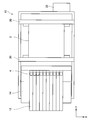
図1、図2に示すように、部品実装機10は、複数の部品フィーダ12と、フィーダ保持部14と、装着ヘッド16及びヘッド移動装置18から構成されるヘッドユニット15と、撮像装置30と、基板コンベア20と、制御装置22と、タッチパネル24を備える。部品実装機10の外部には、部品実装機10と通信可能に構成されたPC26が配置されている。各々の部品フィーダ12は、複数の電子部品4を収容している。部品フィーダ12は、フィーダ保持部14に着脱可能に取り付けられ、装着ヘッド16へ電子部品4を供給する。部品フィーダ12の具体的な構成は特に限定されない。各々の部品フィーダ12は、例えば、巻テープ上に複数の電子部品4を収容するテープ式フィーダ、トレイ上に複数の電子部品4を収容するトレイ式フィーダ、又は、容器内に複数の電子部品4をランダムに収容するバルク式フィーダのいずれであってもよい。また、フィーダ保持部14は、部品実装機10において固定されたものであってもよいし、部品実装機10に対して着脱可能なものであってもよい。
装着ヘッド16は、電子部品4を吸着する吸着ノズル6を有する。吸着ノズル6は、装着ヘッド16に着脱可能に取り付けられている。装着ヘッド16は、吸着ノズル6をZ方向(ここでは鉛直方向)に移動可能であり、部品フィーダ12や回路基板2に対して、吸着ノズル6を接近及び離反させる。また、装着ヘッド16は、吸着ノズル6をその軸線(Z方向に伸びる軸線)の周りに回転可能としている。装着ヘッド16は、部品フィーダ12から電子部品4を吸着ノズル6によって吸着すると共に、吸着ノズル6に吸着された電子部品4を回路基板2上に装着することができる。また、装着ヘッド16は、吸着ノズル6を周方向に回転可能である。なお、装着ヘッド16は、単一の吸着ノズル6を有するものに限られず、複数の吸着ノズル6を有するものであってもよい。また、本実施例の吸着ノズル6は円筒状であり、吸着ノズル6の軸方向と直交する断面(すなわち、XY断面)が略円形であるが、これに限定されない。例えば、吸着ノズルのXY断面は楕円形であってもよいし、その他の形状であってもよい。
ヘッド移動装置18は、部品フィーダ12と回路基板2との間で装着ヘッド16及び固定部材29を移動させる。一例ではあるが、本実施例のヘッド移動装置18は、移動ベース18aをX方向及びY方向に移動させるXYロボットであり、移動ベース18aに対して装着ヘッド16が固定されている。装着ヘッド16とヘッド移動装置18によりヘッドユニット15が構成される。なお、装着ヘッド16は、移動ベース18aに固定されるものに限られず、移動ベース18aに着脱可能に取り付けられるものであってもよい。
撮像装置30は、固定部材29により移動ベース18aに固定されており、移動ベース18aと一体的に移動する。撮像装置30は、カメラ32と、照明用光源(図示省略)と、プリズム(図示省略)を備える。カメラ32は、吸着ノズル6の軸方向(即ち、Z方向)全体が含まれるように、吸着ノズル6を水平方向(即ち、-Y方向)から撮像する。カメラ32には、例えばCCDカメラが用いられる。照明用光源は、LEDにより構成されており、吸着ノズル6の撮像面(本実施例ではZX平面方向の側面)を照らす。プリズムは、カメラ32の光軸を撮像対象に合わせる。照明用光源により吸着ノズル6の軸方向全体が照らされ、その反射光がプリズムで反射してカメラ32に導かれることで、カメラ32は吸着ノズル6を撮像する。また、カメラ32は、装着ヘッド16が吸着ノズル6をその軸線周りに回転させることによって、吸着ノズル6の外形を周方向の異なる複数の方向から撮像することができる。カメラ32によって撮像された画像の画像データは、メモリ40(図3参照)に記憶される。
基板コンベア20は、回路基板2の搬入、位置決め、及び搬出を行う装置である。一例ではあるが、本実施例の基板コンベア20は、一対のベルトコンベアと、回路基板2を下方から支持する支持装置(図示省略)とを有する。
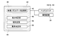
図3に示すように、制御装置22は、メモリ40とCPU44を含むコンピュータを用いて構成されている。メモリ40には吸着ノズルデータ記憶部42が設けられている。吸着ノズルデータ記憶部42は、装着ヘッド16に装着されている吸着ノズル6の下端部の位置の高さ(以下、基準高さHともいう)と、吸着ノズル6の下端から所定高さの幅(以下、基準幅Bともいう)を予め記憶している。図4に示すように、基準高さHは、正常な(すなわち、欠損等のない)吸着ノズル6を予め設定された撮像条件で撮像装置30によって撮像した際の撮像画像100の下端102から、吸着ノズル6の下端部62までの高さである。基準幅Bは、正常な吸着ノズル6を予め設定された撮像条件で撮像した撮像画像100において、吸着ノズル6の下端部62から所定の高さh1における吸着ノズル6の幅である。本実施例の吸着ノズル6はXY断面が略円形であるため、吸着ノズル6をいずれの方向から撮像しても基準幅Bは同一となる。したがって、吸着ノズルデータ記憶部42は、1種類の基準幅Bを記憶している。例えば、XY断面が楕円形の吸着ノズルでは、撮像する方向によって基準幅が異なる。このような吸着ノズルを用いる場合には、複数の基準幅が吸着ノズルデータ記憶部42に記憶され、吸着ノズルを撮像する方向ごとに異なる基準幅が用いられる。吸着ノズル6の基準高さHと基準幅Bに関する情報は、作業者がタッチパネル24にそれらの情報を入力することによって吸着ノズルデータ記憶部42記憶される。なお、吸着ノズル6の基準高さHと基準幅Bに関する情報は、PC26から取得することによって吸着ノズルデータ記憶部42記憶されてもよい。
メモリ40には演算プログラムが記憶されており、CPU44が当該演算プログラムを実行することで、CPU44は高さ判定部46、幅判定部48及び異常判定部50として機能する。高さ判定部46は、メモリ40に記憶されている撮像画像データに基づいて、吸着ノズル6の下端部の位置の高さを算出する。算出された吸着ノズル6の下端部の位置の高さは、メモリ40に記憶される。幅判定部48は、撮像画像データ基づいて、高さ判定部46で算出した最下端の位置の高さから所定の高さh1における吸着ノズル6の幅を算出する。算出された吸着ノズル6の幅は、メモリ40に記憶される。異常判定部50は、吸着ノズルデータ記憶部42に記憶されている吸着ノズル6の基準高さH及び基準幅Bと、高さ判定部46で算出された吸着ノズル6の下端部の位置の高さと、幅判定部48で算出された吸着ノズル6の幅から、吸着ノズル6の異常を判定する。
タッチパネル24は、作業者に各種の情報を提供する表示装置であると共に、作業者からの指示や情報を受け付けるユーザインターフェースである。例えば、タッチパネル24は、制御装置22による吸着ノズル6の異常に関する判定結果を、作業者に対して表示することができる。
図5は、撮像画像データに基づいて吸着ノズル6の異常を判定する処理の一例を示すフローチャートである。吸着ノズル6の異常を判定する処理は、装着ヘッド16に吸着ノズル6が装着された際に実行される。装着ヘッド16に吸着ノズル6を装着する作業を行う際には、吸着ノズル6が他の部材等に接触することによって欠損することがある。このため、装着ヘッド16に吸着ノズル6が装着された際に吸着ノズル6の異常を判定する処理を実行し、吸着ノズル6の欠損異常を判定する。なお、吸着ノズル6の異常判定処理は、装着ヘッド16が電子部品4を回路基板2に実装する毎に実行してもよいし、装着ヘッド16が電子部品4を回路基板2に一定の回数実装する毎に実行してもよいし、一定の時間間隔で実行してもよい。
図5に示すように、まず、撮像装置30によって、装着ヘッド16に装着された吸着ノズル6を撮像する(S10)。吸着ノズル6を撮像する撮像条件は、上記した予め設定された撮像条件と同一とされる。撮像条件を同一とすることで、吸着ノズル6が正常な場合に得られる撮像画像100内の吸着ノズル6の下端部の位置が略一定となる。撮像装置30によって撮像された画像のデータは、メモリ40に記憶される。
次に、制御装置22の高さ判定部46は、ステップS10で撮像された吸着ノズル6の撮像画像から、吸着ノズル6の下端部の位置の高さを算出する(S12)。例えば、高さ判定部46は、まず、撮像画像の下端から上端に向かって伸びる第1検出線(例えば、吸着ノズル6の軸線が写っていると思われる位置に設定した垂直方向に伸びる線)を設定する。次に、高さ判定部46は、第1検出線上の各画素について下端から順に、吸着ノズル6が写っているのか、背景が写っているかを判定する。そして、高さ判定部46は、吸着ノズル6が写っていると判定されるまでの画素数から、撮像画像の下端から吸着ノズル6の下端部までの高さHを算出する。
次に、制御装置22の異常判定部50は、ステップS12で算出された吸着ノズル6の下端部の位置の高さHが、許容範囲内であるか否かを判定する(S14)。許容範囲は、メモリ40に記憶される基準高さHに許容誤差を付加した範囲であり、予めメモリ40に登録されている。算出された吸着ノズル6の下端部の位置の高さが許容範囲内の場合(ステップS14でYESの場合)、異常判定部50は吸着ノズル6が異常ではないと判定し、ステップS16に進む。一方、算出された吸着ノズル6の下端部の位置の高さが許容範囲外の場合(ステップS14でNOの場合)、異常判定部50は吸着ノズル6が異常であると判定し、ステップS24に進む。正常な吸着ノズル6の下端部62の位置の高さを示す基準高さHに基づいて判定することによって、吸着ノズル6の異常をより適切に判定することができる。
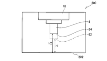
例えば、図6に示すように、吸着ノズル6の下端部が欠損している場合、ステップS12において、高さ判定部46は、撮像画像200に基づいて、吸着ノズル6の下端部64の位置の高さh2を算出する。このとき、吸着ノズル6の下端部が欠損していることにより、吸着ノズル6の下端部64の位置は、正常な吸着ノズル6の下端部62の位置より高くなっている。このため、吸着ノズル6の下端部の位置の高さh2は、撮像画像200の下端202から吸着ノズル6の下端部64までの高さとして算出され、基準高さHより大きくなる。そして、ステップS14において、異常判定部50は、吸着ノズル6の下端部の位置の高さh2が許容範囲外であると判定する。すなわち、吸着ノズル6の下端部が欠損していることにより、吸着ノズル6の下端部の位置の高さh2は許容範囲、すなわち、基準高さHに許容誤差を付加した範囲より大きくなり、異常判定部50は吸着ノズル6が異常であると判定する。また、異常判定部50は、吸着ノズル6の下端部の位置の高さが許容範囲を超えて短い場合にも吸着ノズル6が異常であると判定する。これは、吸着ノズル6の下端部の下方に付着物等が付着していることが推定されるためである。吸着ノズル6の下端部の下方に付着物等が付着していると、吸着ノズル6が電子部品4を正常な姿勢で吸着することができなくなり、回路基板2への電子部品4の実装不良を発生させる虞がある。このため、吸着ノズル6の下端部の位置の高さが許容範囲を超えて短い場合にも、異常判定部50は吸着ノズル6が異常であると判定する。
ステップS14でNOの場合には、制御装置22は、吸着ノズル6が異常であると判定し、部品実装機10を停止する(S24)。また、制御装置22は、吸着ノズル6の異常に関する判定結果を、タッチパネル24に表示すると共に、PC26に送信する。そして、制御装置22は異常判定処理を終了する。
ステップS14でYESの場合、制御装置22の幅判定部48は、ステップS10で撮像された吸着ノズル6の撮像画像から、所定の高さh1における吸着ノズル6の幅を算出する(S16)。幅判定部48は、吸着ノズル6の下端部62から所定の高さh1における吸着ノズル6の幅を算出する。具体的には、幅判定部48は、ステップS12で得られた吸着ノズル6の下端部の位置から所定画素数だけ上方に移動した位置に、水平方向に伸びる第2検出線を設定する。次に、幅判定部48は、第2検出線の中心(吸着ノズル6の軸線があると思われる位置)の画素から左右それぞれの方向について、吸着ノズル6が写っているのか、背景が写っているかを判定する。そして、幅判定部48は、左右それぞれの方向について背景が写っていると判定されるまでの画素数を特定し、それらの和に基づいて吸着ノズル6の幅を算出する。なお、吸着ノズル6の幅の算出方法は、上記の方法に限定されない。例えば、吸着ノズル6の幅は、撮像画像の外側から中心に向かって検出してもよい。具体的には、上記の方法と同様にして、第2検出線を設定する。次に、第2検出線の撮像画像の両端(撮像画像の左端と第2検出線が交差する位置と、撮像画像の右端と第2検出線が交差する位置)の画素からそれぞれ中心に向かって、吸着ノズル6が写っているのか、背景が写っているかを判定する。そして、幅判定部48は、左右それぞれの方向について吸着ノズル6が写っていると判定されるまでの画素数を特定し、第2検出線全体の画素数からそれらの画素数を引いた差に基づいて吸着ノズル6の幅を算出する。
次に、制御装置22の異常判定部50は、ステップS16で算出された吸着ノズル6の幅が、基準幅B以上であるか否かを判定する(S18)。算出された吸着ノズル6の幅が基準幅B以上の場合(ステップS18でYESの場合)、異常判定部50は吸着ノズル6が異常ではないと判定し、ステップS20に進む。一方、算出された吸着ノズル6の幅が基準幅Bより小さい場合(ステップS18でNOの場合)、異常判定部50は吸着ノズル6が異常であると判定し、ステップS24に進む。正常な吸着ノズル6の幅を示す基準幅Bに基づいて判定することによって、吸着ノズル6の異常をより確実に判定することができる。
例えば、図7に示すように、吸着ノズル6の下端部の一部が欠損している場合、ステップS12において、高さ判定部46は、撮像画像300に基づいて、吸着ノズル6の下端部62の位置の高さh3を算出する。算出された吸着ノズル6の下端部の位置の高さh3は、撮像画像300の下端302から、吸着ノズル6の下端部62のうち欠損のない部分までの高さであるため、基準高さHと略一致する。このため、ステップS14において、異常判定部50は、吸着ノズル6の下端部の位置の高さh3が許容範囲内であると判定する。すなわち、ステップS14では、異常判定部50は吸着ノズル6が異常であると判定しない。次に、ステップS16において、幅判定部48は、撮像画像300から吸着ノズル6の下端部62から所定の高さh1における吸着ノズル6の幅b1を算出する。このとき、吸着ノズル6の下端部の一部が欠損していることにより、吸着ノズル6の幅b1は、正常な吸着ノズル6の幅より小さくなっている。このため、吸着ノズル6の幅b1は、基準幅Bより小さくなる。そして、ステップS18において、異常判定部50は、吸着ノズル6の幅b1が基準幅Bより小さいと判定する。すなわち、吸着ノズル6の欠損部66により、吸着ノズル6の下端部62から所定の高さh1における吸着ノズル6の幅b1は、基準幅B(図4参照)より小さくなる。したがって、異常判定部50は吸着ノズル6が異常であると判定する。なお、ステップS18において、異常判定部50は、ステップS16で算出された吸着ノズル6の幅が基準幅Bより大きくても吸着ノズル6が異常であると判定しない。吸着ノズル6の幅が基準幅Bより大きい場合には、吸着ノズル6の側方に付着物等が付着していることが推定される。しかしながら、吸着ノズル6の側方に付着物等が付着していても、吸着ノズル6が電子部品4を吸着する際に影響が少ないため、吸着ノズル6の異常と判定しない。ただし、吸着ノズル6の幅が基準幅Bより大きい場合に、その旨をタッチパネル24に表示したり、PC26に送信したりしてもよい。
ステップS18でNOの場合には、制御装置22は、吸着ノズル6が異常であると判定し、部品実装機10を停止する(S24)。また、制御装置22は、吸着ノズル6の異常に関する判定結果を、タッチパネル24に表示すると共に、PC26に送信する。そして、制御装置22は異常判定処理を終了する。
ステップS18でYESの場合、制御装置22は、吸着ノズル6の全ての方向から撮像した撮像画像に対して上記のステップS14及びステップS18の判定が行われたか否かを判断する(S20)。本実施例では、吸着ノズル6を周方向に略90°ずつ回転した4方向から吸着ノズル6を撮像し、吸着ノズル6の異常を判定する。このため、ステップS20では、4方向全てにおいてステップS14及びステップS18の判定を実行したか否かを判断する。
例えば、図7に示すように吸着ノズル6の一部が欠損している場合(すなわち、欠損部66が存在する場合)、吸着ノズル6の周方向における異なる方向から撮像すると、欠損部66が撮像されないことがある。すなわち、吸着ノズル6を図7に示す状態から90°回転して撮像すると、図8に示す撮像画像400が得られる。このような場合には、欠損部66は撮像装置30の死角に配置される。このため、高さ判定部46によって算出される吸着ノズル6の下端部62の位置の高さh4は、基準高さHと略一致し、幅判定部48が算出する吸着ノズル6の下端部62から所定の高さh1における幅b2は、基準幅Bと略一致する。すなわち、吸着ノズル6の下端部に欠損部66が存在していても、撮像装置30によって撮像される方向によっては、吸着ノズル6の異常を判定できない場合がある。吸着ノズル6を略90°ずつ回転させた4方向から吸着ノズル6を撮像すると、吸着ノズル6の外周全体の撮像画像を取得することができる。このため、吸着ノズル6を略90°ずつ回転させた4方向から吸着ノズル6を撮像して吸着ノズル6の異常を判定することによって、吸着ノズル6の一部に欠損がある場合であっても異常を漏れなく検出することができる。なお、本実施例では、吸着ノズル6を略90°ずつ回転させた4方向から吸着ノズル6を撮像して吸着ノズル6の異常を判定しているが、このような構成に限定されない。例えば、略90°より小さい角度ずつ回転させ、4方向より多くの方向から吸着ノズル6を撮像して吸着ノズル6の異常を判定してもよい。
吸着ノズル6を略90°ずつ回転した4方向のいずれかについて異常を判定していない場合(ステップS20でNOの場合)、制御装置22は、装着ヘッド16によって吸着ノズル6を略90°回転する(S22)。制御装置22は、ステップS22で吸着ノズル6を略90°回転させると、ステップS10に戻り、略90°回転した吸着ノズル6に対してステップS10~S20の処理を繰り返す。すなわち、略90°回転した吸着ノズル6の撮像画像に基づいて、吸着ノズル6の異常を判定する。吸着ノズル6を略90°ずつ回転した4方向の全てについて異常を判定した場合(ステップS20でYESの場合)、制御装置22は異常判定処理を終了する。
本実施例の部品実装機10は、幅判定部48を備えていることによって、吸着ノズル6の下端部の一部分のみが欠損した場合であっても、吸着ノズル6の異常を正確に判定することができる。すなわち、吸着ノズル6の下端部の位置の高さに基づいて吸着ノズル6の異常を判定する処理では検出できない異常を検出することができる。また、異常判定部50は、幅判定部48によって算出された吸着ノズル6の所定の高さの幅と基準幅Bを比較することによって吸着ノズル6の異常を判定する。すなわち、所定の高さの幅について正常な吸着ノズル6と比較するため、撮像画像全体について画像処理する必要がなく、異常判定の処理時間を短くすることができる。
なお、本実施例では、装着ヘッド16によって吸着ノズル6が周方向に回転可能となっているが、このような構成に限定されない。吸着ノズル6の周方向における外周全体を撮像できるように吸着ノズル6と撮像装置30とが配置されていればよく、例えば、撮像装置30が吸着ノズル6の周方向に回転可能に移動してもよいし、吸着ノズル6の周方向に少なくとも4つ以上の複数の撮像装置30を設置してもよい。
また、本実施例では、吸着ノズルデータ記憶部42に基準幅Bを予め記憶させているが、このような構成に限定されない。例えば、吸着ノズル6の下端部から所定の高さの位置のXY断面が円形である場合、4方向から撮像した撮像画像から算出した吸着ノズル6の下端部から所定の高さにおける幅に基づいて、異常判定部50が吸着ノズル6の異常を判定してもよい。具体的には、制御装置22は、吸着ノズル6を略90°ずつ回転した4枚の撮像画像を取得する。そして、上記の手順によって、4枚の撮像画像のそれぞれについて、吸着ノズル6の下端部から所定の高さにおける幅を算出する。異常判定部50は、4枚の撮像画像から算出された吸着ノズル6の幅を比較し、4枚全てにおいて当該幅が略等しい場合に吸着ノズル6が異常ではないと判定し、4枚のうち1つでも当該幅が他のものと異なる場合に吸着ノズル6が異常であると判定する。このような構成では、予め基準幅を記憶させなくとも、吸着ノズル6の異常を判定することができる。
本明細書または図面に説明した技術要素は、単独であるいは各種の組合せによって技術的有用性を発揮するものであり、出願時請求項記載の組合せに限定されるものではない。また、本明細書または図面に例示した技術は複数目的を同時に達成するものであり、そのうちの一つの目的を達成すること自体で技術的有用性を持つものである。
Claims (5)
- 電子部品を基板に実装する部品実装機であって、
前記電子部品を吸着する吸着ノズルと、
前記吸着ノズルの側方から前記吸着ノズルを撮像する撮像装置と、
前記撮像装置で撮像された前記吸着ノズルの撮像画像から、上下方向と直交する方向の前記吸着ノズルの幅を計測する幅判定部と、
前記幅判定部で計測された前記吸着ノズルの幅から前記吸着ノズルの異常を判定する異常判定部と、を備える、部品実装機。 - 前記幅判定部は、前記吸着ノズルの下端から所定の高さにおける前記吸着ノズルの幅を計測し、
前記異常判定部は、前記幅判定部で計測された前記吸着ノズルの幅が予め設定された基準幅と異なる場合に前記吸着ノズルが異常であると判定する、請求項1に記載の部品実装機。 - 前記撮像装置は、前記吸着ノズルの周方向における複数の方向から前記吸着ノズルを撮像し、
前記異常判定部は、前記複数の方向から撮影された前記吸着ノズルの複数の撮像画像の少なくとも1つにおいて、前記幅判定部で計測された前記吸着ノズルの幅が前記基準幅と異なる場合に前記吸着ノズルが異常であると判定する、請求項2に記載の部品実装機。 - 前記複数の撮影画像は、前記吸着ノズル及び前記撮像装置を平面視したときに、前記吸着ノズルに対して前記撮像装置を前記周方向に互いに略90°回転した位置から撮像した画像である、請求項3に記載の部品実装機。
- 前記基準幅は、前記吸着ノズルが正常である場合の前記所定の高さにおける前記吸着ノズルの幅である、請求項2~4のいずれか一項に記載の部品実装機。
Priority Applications (2)
| Application Number | Priority Date | Filing Date | Title |
|---|---|---|---|
| JP2018560305A JP6795622B2 (ja) | 2017-01-06 | 2017-01-06 | 部品実装機 |
| PCT/JP2017/000313 WO2018127977A1 (ja) | 2017-01-06 | 2017-01-06 | 部品実装機 |
Applications Claiming Priority (1)
| Application Number | Priority Date | Filing Date | Title |
|---|---|---|---|
| PCT/JP2017/000313 WO2018127977A1 (ja) | 2017-01-06 | 2017-01-06 | 部品実装機 |
Publications (1)
| Publication Number | Publication Date |
|---|---|
| WO2018127977A1 true WO2018127977A1 (ja) | 2018-07-12 |
Family
ID=62789105
Family Applications (1)
| Application Number | Title | Priority Date | Filing Date |
|---|---|---|---|
| PCT/JP2017/000313 Ceased WO2018127977A1 (ja) | 2017-01-06 | 2017-01-06 | 部品実装機 |
Country Status (2)
| Country | Link |
|---|---|
| JP (1) | JP6795622B2 (ja) |
| WO (1) | WO2018127977A1 (ja) |
Cited By (1)
| Publication number | Priority date | Publication date | Assignee | Title |
|---|---|---|---|---|
| JP7578552B2 (ja) | 2021-07-12 | 2024-11-06 | ヤマハ発動機株式会社 | 部品実装装置 |
Citations (2)
| Publication number | Priority date | Publication date | Assignee | Title |
|---|---|---|---|---|
| JPH06104596A (ja) * | 1992-08-07 | 1994-04-15 | Yamaha Motor Co Ltd | 部品装着方法及び同装置 |
| JP2008124293A (ja) * | 2006-11-14 | 2008-05-29 | Fuji Mach Mfg Co Ltd | 画像処理機能付き撮像装置及び検査システム |
-
2017
- 2017-01-06 WO PCT/JP2017/000313 patent/WO2018127977A1/ja not_active Ceased
- 2017-01-06 JP JP2018560305A patent/JP6795622B2/ja active Active
Patent Citations (2)
| Publication number | Priority date | Publication date | Assignee | Title |
|---|---|---|---|---|
| JPH06104596A (ja) * | 1992-08-07 | 1994-04-15 | Yamaha Motor Co Ltd | 部品装着方法及び同装置 |
| JP2008124293A (ja) * | 2006-11-14 | 2008-05-29 | Fuji Mach Mfg Co Ltd | 画像処理機能付き撮像装置及び検査システム |
Cited By (1)
| Publication number | Priority date | Publication date | Assignee | Title |
|---|---|---|---|---|
| JP7578552B2 (ja) | 2021-07-12 | 2024-11-06 | ヤマハ発動機株式会社 | 部品実装装置 |
Also Published As
| Publication number | Publication date |
|---|---|
| JPWO2018127977A1 (ja) | 2019-08-08 |
| JP6795622B2 (ja) | 2020-12-02 |
Similar Documents
| Publication | Publication Date | Title |
|---|---|---|
| JP4767995B2 (ja) | 部品実装方法、部品実装機、実装条件決定方法、実装条件決定装置およびプログラム | |
| JP6706695B2 (ja) | 座標データ生成装置及び座標データ生成方法 | |
| JP6466960B2 (ja) | 装着機及び装着機を用いた電子部品の吸着姿勢検査方法 | |
| WO2017064774A1 (ja) | 基板作業システムおよび部品実装装置 | |
| JP5963129B2 (ja) | 印刷検査装置、印刷検査システム、検査データの統計方法、プログラム及び基板の製造方法 | |
| JP6534448B2 (ja) | 部品実装装置 | |
| CN111727672B (zh) | 元件安装机 | |
| JP6795622B2 (ja) | 部品実装機 | |
| JP6726310B2 (ja) | 部品実装機 | |
| JP2007123807A (ja) | 部品移載装置、表面実装機、部品検査装置および異常判定方法 | |
| JP6654109B2 (ja) | 判断装置 | |
| JP2003304095A (ja) | 吸着ノズルの電子回路部品保持能力取得プログラムおよび電子回路部品ハンドリング装置 | |
| US20130110436A1 (en) | Inspection apparatus, processing apparatus, information processing apparatus, object manufacturing apparatus, and manufacturing method for an object | |
| JP4707607B2 (ja) | 部品認識データ作成用画像取得方法及び部品実装機 | |
| JP4520324B2 (ja) | 検査結果報知装置及び実装システム | |
| JP6855597B2 (ja) | 作業機、及び極性の判定方法 | |
| JP6770069B2 (ja) | 測定装置 | |
| JP6896859B2 (ja) | 撮像装置、表面実装機及び検査装置 | |
| JP6231397B2 (ja) | 部品認識装置、部品移載装置および部品実装装置 | |
| JP2017168637A (ja) | 部品実装機及びヘッドユニット | |
| JP6924712B2 (ja) | 部品実装装置および部品検査方法 | |
| WO2022259337A1 (ja) | 部品実装機 | |
| WO2026105333A1 (ja) | 基板作業装置 | |
| WO2024075252A1 (ja) | 撮像位置決定装置、撮像装置及び撮像位置決定方法 | |
| JP2024024767A (ja) | 部品実装装置及び部品の吸着状態検査方法 |
Legal Events
| Date | Code | Title | Description |
|---|---|---|---|
| 121 | Ep: the epo has been informed by wipo that ep was designated in this application |
Ref document number: 17890262 Country of ref document: EP Kind code of ref document: A1 |
|
| ENP | Entry into the national phase |
Ref document number: 2018560305 Country of ref document: JP Kind code of ref document: A |
|
| NENP | Non-entry into the national phase |
Ref country code: DE |
|
| 122 | Ep: pct application non-entry in european phase |
Ref document number: 17890262 Country of ref document: EP Kind code of ref document: A1 |