WO2018123607A1 - 対空標識、画像処理装置、画像処理方法、及び、プログラム - Google Patents
対空標識、画像処理装置、画像処理方法、及び、プログラム Download PDFInfo
- Publication number
- WO2018123607A1 WO2018123607A1 PCT/JP2017/044840 JP2017044840W WO2018123607A1 WO 2018123607 A1 WO2018123607 A1 WO 2018123607A1 JP 2017044840 W JP2017044840 W JP 2017044840W WO 2018123607 A1 WO2018123607 A1 WO 2018123607A1
- Authority
- WO
- WIPO (PCT)
- Prior art keywords
- air
- circles
- circle
- hue
- sign
- Prior art date
Links
Images


Classifications
-
- G—PHYSICS
- G01—MEASURING; TESTING
- G01C—MEASURING DISTANCES, LEVELS OR BEARINGS; SURVEYING; NAVIGATION; GYROSCOPIC INSTRUMENTS; PHOTOGRAMMETRY OR VIDEOGRAMMETRY
- G01C7/00—Tracing profiles
- G01C7/02—Tracing profiles of land surfaces
- G01C7/04—Tracing profiles of land surfaces involving a vehicle which moves along the profile to be traced
-
- G—PHYSICS
- G01—MEASURING; TESTING
- G01C—MEASURING DISTANCES, LEVELS OR BEARINGS; SURVEYING; NAVIGATION; GYROSCOPIC INSTRUMENTS; PHOTOGRAMMETRY OR VIDEOGRAMMETRY
- G01C15/00—Surveying instruments or accessories not provided for in groups G01C1/00 - G01C13/00
- G01C15/02—Means for marking measuring points
- G01C15/06—Surveyors' staffs; Movable markers
-
- G—PHYSICS
- G06—COMPUTING; CALCULATING OR COUNTING
- G06T—IMAGE DATA PROCESSING OR GENERATION, IN GENERAL
- G06T17/00—Three dimensional [3D] modelling, e.g. data description of 3D objects
- G06T17/05—Geographic models
-
- G—PHYSICS
- G06—COMPUTING; CALCULATING OR COUNTING
- G06T—IMAGE DATA PROCESSING OR GENERATION, IN GENERAL
- G06T7/00—Image analysis
- G06T7/10—Segmentation; Edge detection
- G06T7/11—Region-based segmentation
-
- G—PHYSICS
- G06—COMPUTING; CALCULATING OR COUNTING
- G06T—IMAGE DATA PROCESSING OR GENERATION, IN GENERAL
- G06T7/00—Image analysis
- G06T7/60—Analysis of geometric attributes
- G06T7/62—Analysis of geometric attributes of area, perimeter, diameter or volume
-
- G—PHYSICS
- G06—COMPUTING; CALCULATING OR COUNTING
- G06T—IMAGE DATA PROCESSING OR GENERATION, IN GENERAL
- G06T7/00—Image analysis
- G06T7/90—Determination of colour characteristics
-
- G—PHYSICS
- G06—COMPUTING; CALCULATING OR COUNTING
- G06V—IMAGE OR VIDEO RECOGNITION OR UNDERSTANDING
- G06V10/00—Arrangements for image or video recognition or understanding
- G06V10/20—Image preprocessing
- G06V10/255—Detecting or recognising potential candidate objects based on visual cues, e.g. shapes
-
- G—PHYSICS
- G06—COMPUTING; CALCULATING OR COUNTING
- G06V—IMAGE OR VIDEO RECOGNITION OR UNDERSTANDING
- G06V10/00—Arrangements for image or video recognition or understanding
- G06V10/40—Extraction of image or video features
- G06V10/56—Extraction of image or video features relating to colour
-
- G—PHYSICS
- G06—COMPUTING; CALCULATING OR COUNTING
- G06V—IMAGE OR VIDEO RECOGNITION OR UNDERSTANDING
- G06V20/00—Scenes; Scene-specific elements
- G06V20/10—Terrestrial scenes
- G06V20/13—Satellite images
-
- G—PHYSICS
- G06—COMPUTING; CALCULATING OR COUNTING
- G06V—IMAGE OR VIDEO RECOGNITION OR UNDERSTANDING
- G06V20/00—Scenes; Scene-specific elements
- G06V20/10—Terrestrial scenes
- G06V20/17—Terrestrial scenes taken from planes or by drones
-
- G—PHYSICS
- G06—COMPUTING; CALCULATING OR COUNTING
- G06T—IMAGE DATA PROCESSING OR GENERATION, IN GENERAL
- G06T2207/00—Indexing scheme for image analysis or image enhancement
- G06T2207/10—Image acquisition modality
- G06T2207/10024—Color image
-
- G—PHYSICS
- G06—COMPUTING; CALCULATING OR COUNTING
- G06T—IMAGE DATA PROCESSING OR GENERATION, IN GENERAL
- G06T2207/00—Indexing scheme for image analysis or image enhancement
- G06T2207/10—Image acquisition modality
- G06T2207/10032—Satellite or aerial image; Remote sensing
-
- G—PHYSICS
- G06—COMPUTING; CALCULATING OR COUNTING
- G06T—IMAGE DATA PROCESSING OR GENERATION, IN GENERAL
- G06T2207/00—Indexing scheme for image analysis or image enhancement
- G06T2207/30—Subject of image; Context of image processing
- G06T2207/30181—Earth observation
-
- G—PHYSICS
- G06—COMPUTING; CALCULATING OR COUNTING
- G06V—IMAGE OR VIDEO RECOGNITION OR UNDERSTANDING
- G06V2201/00—Indexing scheme relating to image or video recognition or understanding
- G06V2201/12—Acquisition of 3D measurements of objects
Definitions
- the present technology relates to an anti-air sign, an image processing device, an image processing method, and a program, and in particular, for example, an anti-air sign that enables an anti-air sign to be accurately detected from a captured image obtained by photographing the anti-air sign.
- the present invention relates to a processing device, an image processing method, and a program.
- Patent Document 1 For example, by taking a picture with an anti-air sign installed, and creating a three-dimensional model based on the orientation point where the anti-air sign shown in the captured image obtained by the picture is installed, you can measure buildings and other things in real space An easy technique has been proposed (see, for example, Patent Document 1).
- the present technology has been made in view of such a situation, and makes it possible to accurately detect an anti-air sign from a photographed image obtained by photographing the anti-air sign.
- the image processing apparatus or the program of the present technology has a plane shape in which a plurality of circles are arranged concentrically, and an image obtained by photographing an anti-air sign in which the adjacent circles of the plurality of circles have different luminance or hue
- a candidate area extracting unit that extracts a candidate area that is a candidate for an area in which the anti-air sign appears, a feature quantity extracting unit that extracts a feature quantity of the candidate area, and the anti-air sign based on the feature quantity.
- An image processing apparatus including an identifying unit to be identified, or a program for causing a computer to function as such an image processing apparatus.
- the image processing method of the present technology has a planar shape in which a plurality of circles are concentrically arranged, and from a captured image obtained by photographing an anti-air sign in which the luminance or hue of adjacent circles of the plurality of circles are different from each other,
- An image processing method comprising: extracting a candidate area that is a candidate for an area in which an anti-air sign appears; extracting a feature quantity of the candidate area; and identifying the anti-air sign based on the feature quantity is there.
- a plurality of circles have a planar shape in which concentric circles are arranged, and adjacent circles of the plurality of circles have different brightness or hue.
- Candidate areas, which are candidates for areas where the anti-aircraft sign is reflected, are extracted from the captured image obtained by capturing the signs, and feature quantities of the candidate areas are extracted. Then, the anti-air sign is identified based on the feature amount.
- the anti-air marker of the present technology is an anti-air marker having a planar shape in which a plurality of circles having different radii are concentrically arranged, and adjacent circles of the plurality of circles have different luminance or hue.
- the planar shape is a shape in which a plurality of circles having different radii are arranged concentrically, and the luminance or hue of adjacent circles among the plurality of circles is different.
- the image processing apparatus may be an independent apparatus or an internal block constituting one apparatus.
- the components of the image processing apparatus can be distributed and incorporated in a plurality of apparatuses.
- the program can be provided by being transmitted via a transmission medium or by being recorded on a recording medium.
- FIG. 1 is a plan view showing a first example of an anti-air sign 10.
- FIG. 4 is a plan view showing a second example of the anti-air sign 10.
- FIG. 6 is a plan view showing a third example of the anti-air sign 10.
- 3 is a perspective view showing an example of a second multi-circular marker as the anti-air marker 10.
- FIG. It is a figure explaining the color of the anti-air mark 10. It is a figure explaining the presence or absence of generation
- FIG. 2 is a block diagram illustrating a configuration example of computer hardware as a cloud server 30.
- FIG. It is a block diagram which shows the functional structural example of the cloud server 30 which functions as an image processing apparatus (detection apparatus).
- 5 is a flowchart for explaining an example of detection processing for detecting an anti-air mark 10. It is a flowchart explaining the example of the detailed process of binarization of each pixel of a picked-up image. It is a figure which shows the example of the template image of the anti-air marker 10 (circle 11 and 12). It is a figure which shows the example of the filter which emphasizes the color attached
- FIG. 2 is a block diagram illustrating a configuration example of a drone 20.
- FIG. It is a figure explaining the outline
- FIG. 1 is a diagram illustrating an outline of an embodiment of a soil volume measurement system to which the present technology is applied.
- soil volume is measured by UAV (Unmanned Aerial Vehicle).
- an anti-air sign 10 is installed on the ground.
- the anti-air sign 10 can be installed manually, or can be installed by spreading from a flying body such as an unmanned aircraft such as a drone or an aircraft operated by a person. Furthermore, the anti-air sign 10 itself may be moved by installing the anti-air sign 10 on the back of the drone.
- the anti-air sign 10 is aerial shot.
- a camera 21 is mounted on the drone 20, the drone 20 is caused to fly, and the anti-air sign 10 is photographed (aerial shooting of the anti-air sign 10) with the camera 21 mounted on the drone 20.
- a captured image (for example, a still image) obtained by capturing the anti-air sign 10 with the camera 21 is transmitted to, for example, the cloud server 30 by wireless communication or wired communication.
- the cloud server 30 detects the anti-air sign 10 shown in the photographed image by performing image processing of the photographed image from the camera 21. Further, the cloud server 30 creates a three-dimensional model of the ground topography using the detection result of the anti-air sign 10, and measures the soil volume of the ground topography from the three-dimensional model, and measures the soil volume. The measurement result of is output.
- the processing performed by the cloud server 30 described above can be performed by the drone 20 instead of the cloud server 30.
- the process performed by the cloud server 30 can be shared between the drone 20 and the cloud server 30.
- the method of aerial shooting of the anti-air sign 10 is not limited to the method using the drone 20. That is, aerial photography of the anti-air sign 10 can be performed using, for example, a flying object that a person rides and controls, an artificial satellite, or the like, in addition to a method using an unmanned aircraft such as the drone 20.
- the anti-air sign 10 paper or plastic on which a predetermined figure is printed can be employed. Further, as the anti-air mark 10, a stack of flat materials such as plastic and rubber having a predetermined shape can be adopted. Furthermore, as the anti-air marker 10, a display panel such as an LCD (Liquid Crystal Display) or an organic EL (Electro Luminescence) display that displays a predetermined figure can be adopted. Further, as the anti-air marking 10, it is also possible to adopt an unfolded deployment such as a reflex board.
- LCD Liquid Crystal Display
- organic EL Electro Luminescence
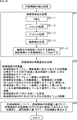
- FIG. 2 is a flowchart for explaining an example of a work flow of soil volume measurement performed by the soil volume measurement system of FIG.
- step S11 an administrator who performs soil volume measurement prepares a prior plan for soil volume measurement.
- determination of the flight route of the drone 20, determination of the orientation point (position to be used) where the anti-air sign 10 is installed, and the like are performed.
- step S12 the anti-air marking 10 is installed at the control points set at intervals of about several hundred meters, for example, according to the advance plan.
- the installation of the anti-air sign 10 can be performed by, for example, a human hand or a movable robot. Further, the anti-air marking 10 itself may be a movable robot.
- step S13 the horizontal position (latitude and longitude) and altitude of the orientation point where the anti-air sign 10 is installed are measured.
- step S14 the drone 20 is caused to fly in accordance with the advance plan, and the camera 21 mounted on the drone 20 is used to take an aerial view of the anti-air sign 10, that is, the ground on which the anti-air sign 10 is installed (as an object of soil measurement). Photographing of a predetermined ground surface range) is performed.
- the aerial shooting of the anti-air sign 10 one or more captured images are captured as captured image data. Further, the aerial shooting of the anti-air sign 10 is performed such that when the shooting ranges reflected in all the shot images are collected, the entire range in which the anti-air marking 10 is installed is reflected in the collection of shooting ranges.
- the aerial shooting of the anti-air sign 10 is performed so that a shooting range reflected in a certain shot image and a shooting range reflected in another shot image overlap.
- step S15 the anti-air sign 10 installed on the ground is collected, and photographed image data obtained by capturing the anti-air sign 10 with the camera 21 is uploaded (transmitted) to the cloud server 30.
- step S ⁇ b> 16 the cloud server 30 performs a detection process for detecting the anti-air mark 10 (image) reflected in the captured image from the captured image captured by the camera 21.
- step S17 the cloud server 30 uses the horizontal position and altitude of the orientation point measured in step S13 and the detection result data of the anti-air marker 10 obtained by the detection process performed in step S16 to perform three-dimensional Process to generate model data.
- step S18 the cloud server 30 performs a soil volume measurement process using the ground three-dimensional model data, and performs a process of outputting measurement result data of the soil volume measurement.
- FIG. 3 is a plan view showing a first example of the anti-air sign 10.
- the anti-air sign 10 in FIG. 3 is an anti-air sign called star type, X (X) type, plus (+) type, respectively.
- a range that overlaps a shooting range that appears in one shot image and a shooting range that appears in another shot image a time for uploading the shot image to the cloud server 30, and the cloud server 30 takes a shot. It is possible to reduce a load or the like when processing an image.
- the anti-air sign 10 (image thereof) shown in the photographed image becomes small.
- the anti-air sign 10 is a sign with white and black, such as a star-shaped, X-shaped, or plus-type anti-air sign, white expansion, black contraction, etc.
- a snow cover may cause a similar pattern between the black soil on the ground and the snow white, which may reduce the detection accuracy for detecting the anti-air sign 10 from the captured image.
- the intersection of the boundary lines (extension lines) between white and black (areas marked with) is detected as the center of the anti-air sign 10. Is done. Therefore, when white expansion and black contraction occur, the detection accuracy for detecting the center of the anti-air marker 10 may decrease.
- FIG. 4 is a plan view showing a second example of the anti-air sign 10.
- a black circle is arranged in a white rectangle.
- the anti-air sign 10 of FIG. 4 has a simple configuration as compared to the anti-air sign 10 of FIG. 3, so an object that appears in a black circle shape in the captured image may be erroneously detected as the anti-air sign 10. obtain.
- the anti-air sign 10 of FIG. 4 has one circle, it can be said to be a single circular sign.
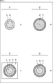
- FIG. 5 is a plan view showing a third example of the anti-air sign 10.
- 5 has a plane shape in which a plurality of circles having different radii are arranged concentrically, and the adjacent circles of the plurality of circles have different hues.
- planar shape means the shape of the object drawn on the plan view when the object is represented on the plan view.
- the anti-air sign 10 of FIG. 5 has a plurality of circles, it can be said to be a multi-circle sign.
- the anti-air marker 10 of a plurality of circular markers (the same applies to the single circular marker in FIG. 4), the anti-air marker 10 is detected without considering the direction (rotation) of the anti-air marker 10 shown in the captured image. It is possible to reduce the load of the detection process for detecting the anti-air mark 10 in the cloud server 30. Furthermore, the center of the anti-air mark 10 can be easily detected.
- FIG. 5A is a plan view showing an example of a first multi-circular sign as the anti-air sign 10.
- 5A includes three circles 11, 12, and 13 having different radii arranged concentrically and includes the three circles 11 to 13, for example, a square or a rectangle. It has a planar shape in which a rectangular frame region 14 is arranged.
- the color of the circle 11 with the smallest radius is, for example, blue, which is one of chromatic colors (colors with hue), and the color of the circle 12 with the second smallest radius is, for example, , The other chromatic color is red. Furthermore, the color of the circle 13 with the third smallest (largest) radius is, for example, black which is one of achromatic colors.
- the hues of the adjacent circles are different. Therefore, the hues of the adjacent circles 11 and 12 are different, and the hues of the adjacent circles 12 and 13 are different. If so, the hues of the non-adjacent circles 11 and 13 may be the same.
- achromatic black chromatic red, and achromatic black can be employed.
- the frame area 14 can be made of, for example, rectangular paper or plastic.
- the anti-air mark 10 can be formed by printing circles 11 to 13 on the frame area 14 of paper, plastic, or the like.
- the circles 11 to 13 and the frame region 14 can be made of a flat plate material such as plastic or rubber, for example.
- the anti-air marking 10 is configured by stacking the flat materials as the circles 11 to 13 and the frame region 14 in order from the bottom to the frame region 14 and the circles 13, 12, and 11. Can do.
- the anti-air sign 10 is configured by a display panel such as an LCD or an organic EL display, for example, and the circle 11 to 13 and the frame region 14 are displayed on the display panel, thereby functioning as the anti-air sign 10. Can do.
- FIG. 5B is a plan view showing an example of a second multi-circular sign as the anti-air sign 10.
- the anti-air marker 10 of FIG. 5B has a configuration in which three circles 11 to 13 having different radii are arranged concentrically.
- FIG. 5C is a plan view showing an example of a third multiple circular sign as the anti-air sign 10.
- the anti-air marking 10 in FIG. 5C has a configuration in which the circle 13 and the frame region 14 are not provided with respect to the multiple circular marking in FIG. 5A. Therefore, the anti-air marker 10 of FIG. 5C has a configuration in which two circles 11 and 12 having different radii are arranged concentrically.
- FIG. 5D is a plan view showing an example of a fourth multi-circular sign as the anti-air sign 10.
- the anti-air sign 10 of FIG. 5D has a configuration in which the circle 11 and the frame region 14 are not provided with respect to the multi-circular sign of FIG. 5A. Therefore, the anti-air marker 10 of FIG. 5D has a configuration in which two circles 12 and 13 having different radii are arranged concentrically.
- the anti-air marking 10 for example, a configuration in which the frame region 14 is provided in the multi-circular label of C and D in FIG. 5, or four or more circles having different radii are arranged concentrically. A configuration can be employed.
- FIG. 6 is a perspective view showing an example of a second multi-circular sign as the anti-air sign 10 of FIG. 5B.
- the second multi-circular sign is composed of three circles 11 to 13 in a planar shape, it is hereinafter also referred to as a three-circle sign.
- a three-circle sign as the anti-air sign 10 of FIG. 6 is a cylindrical member having a low height (hereinafter also referred to as a cylindrical member 11) to be a circle 11, and a flat plate-like member (hereinafter to be referred to as a cylindrical member 11). And a circular member 12) and a flat plate-like circular member (hereinafter also referred to as a circular member 13) to be a circle 13.
- the anti-air sign 10 of FIG. 6 is configured by stacking the cylindrical member 11, the circular members 12 and 13 in the order of the circular members 13, 12 and the cylindrical member 11 from the bottom to the top.
- the cylindrical member 11 can be made of, for example, plastic (ABS resin) or the like. Furthermore, the columnar member 11 has a hollow interior, and an illuminance detection device including an illuminance sensor that detects the illuminance of the anti-air sign 10 (upper), a communication device including an antenna and a circuit that performs wireless communication, and further, the illuminance A recording device (not shown) including a recording medium such as a semiconductor for recording information detected by the detection device in time series can be incorporated.
- the anti-air marker 10 may incorporate these illuminance detection devices and the like in a part other than the columnar member 11 of the anti-air marker.
- the anti-air sign 10 may include a sensor other than the illuminance sensor incorporated in the cylindrical member 11 or other members, and data related to the anti-air sign detected by the sensor may be transmitted by a communication device or recorded by a recording device. .
- the illuminance detecting device and the communication device are built in the cylindrical member 11, the information on the illuminance detected by the illuminance detecting device in the anti-air sign 10 can be transmitted by the communication device.
- Information such as illuminance transmitted from the anti-air sign 10 can be received by the cloud server 30 and used for processing in the cloud server 30.
- the columnar member 11 can be configured in a flat circular shape like the circular members 12 and 13.
- the apparatus incorporated in the cylindrical member 11 can be taken out (removed) from the cylindrical member 11 for charging or the like.
- the circular member 12 can be composed of a member that is not easily discolored by ultraviolet rays, such as rubber. By configuring the circular member 12 with a member that is not easily discolored by ultraviolet rays, when the hue of the color attached to the circular member 12 is used for detection of the anti-air mark 10, It can suppress that the detection accuracy of the anti-air mark 10 falls.
- the circular member 13 can be made of an insulator such as polypropylene, for example. By configuring the circular member 13 with an insulator, the circular member 12, the columnar member 11, the communication device incorporated in the columnar member 11, and the ground (earth) are electrically connected. It is possible to prevent connection.
- an insulator such as polypropylene
- At least the hue of the color of the circular member 12 is used for identification of the anti-air marker 10 (extraction of candidate regions that are candidates for the anti-air marker 10 from the captured image). It is done.
- the circular member 12 contacts the ground when the anti-air mark 10 is installed on the ground. Since various colors may exist as the color of the installation location of the anti-air sign 10, depending on the color of the installation location of the anti-air sign 10, the color of the circular member 12 and the location of the installation location of the anti-air sign 10 are determined in the photographed image. A large color mixture occurs between colors, and the identification of the anti-air mark 10 is affected according to the color mixture level.
- the anti-air sign 10 by providing the circular member 13, it is possible to prevent color mixing between the color of the circular member 12 and the color of the place where the anti-air sign 10 is installed.
- the color mixture between the colors of the circular members 12 and 13 affects the identification of the anti-air mark 10.
- the degree of color mixing between the color of the circular member 12 and the color of the anti-air mark 10 installation location depends on the installation location of the anti-air sign 10. Depends on the color of the. Therefore, the degree to which the color mixture between the color of the circular member 12 and the color of the installation place of the anti-air sign 10 affects the identification of the anti-air sign 10 varies depending on the color of the installation place of the anti-air sign 10.
- the anti-air sign 10 is configured by providing the circular member 13, the degree of color mixing between the colors of the circular members 12 and 13 varies depending on the color of the place where the anti-air sign 10 is installed. do not do. Therefore, the degree to which the color mixture between the colors of the circular members 12 and 13 affects the identification of the anti-air mark 10 does not vary depending on the color of the place where the anti-air mark 10 is installed.
- a person carries a certain number of anti-air signs 10 in consideration of carrying the anti-air sign 10 when the person installs the anti-air sign 10.
- a size of about 30 cm in diameter such as a 10-30 cm square, can be employed.
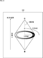
- FIG. 7 is a diagram for explaining the colors of the anti-air sign 10.
- the cloud server 30 detects the anti-air sign 10 shown in the captured image from the captured image obtained by the aerial shooting.
- the cloud server 30 detects the anti-air sign 10 using, for example, the hue of a circle (circular member) 12. That is, the cloud server 30 detects the anti-air marker 10 using, for example, the hue itself of the circle 12 or the distance between the hue of the circle 12 and the hue of the circle 11 adjacent to the circle 12.
- the colors of the circles 11 and 12 have a certain altitude, for example, It is effective that the color is less likely to cause color mixing (color with a low degree of color mixing) when shooting from an altitude at which aerial photography is planned.
- the area of the portion of the circle 12 excluding the circle 11 is about 1.0 to 3.0 times the area of the circle 11, and the discriminability of the circle 12 is increased. Has been confirmed.
- the combination of the colors of the circles 11 and 12 is a combination that is as small as possible that it exists in the natural world. Is effective.
- the color combinations of the circles 11 and 12 are combinations in which the hues of the respective colors are as different as possible.
- the combinations of the colors of the circles 11 and 12 are combinations with the lowest possible degree of color mixing when shooting from a certain altitude, that is, for example, the hue of the circle 11 and the hue of the circle 12 obtained from the captured image. It is effective that the distance is as large as possible.
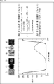
- FIG. 7 shows an example of the histogram of the hue of each pixel of the circles 11 and 12 obtained from the captured image obtained by capturing the anti-air marker 10.
- the circle 12 means an annular portion excluding the circle 11 in the entire circle as the circle 12 unless otherwise specified.
- pixels of a circle 11 (estimated region) and a circle 12 (estimated pixel) are detected from the captured image, and each of the pixels of the circles 11 and 12 is targeted.
- the frequency (number of pixels) of pixels having a hue is shown.
- the horizontal axis represents hue
- the vertical axis represents frequency
- the hue histogram (hereinafter also referred to as the hue histogram) for the pixels of the circles 11 and 12 detected from the captured image includes, for example, a distribution having a peak at the first hue as shown in FIG. There are two distributions, a distribution having a peak at the second hue.
- the distance between the hues of the circles 11 and 12 for example, the distance between the peaks of the two distributions existing in the hue histogram (the difference in hue between the peaks) can be employed.
- the distance between the hues of the circles 11 and 12 for example, a difference in integrated values such as an average value of hues of the pixels of the circles 11 and 12 detected from the captured image can be employed.
- the hue distance DF of each of the circles 11 and 12 for example, if the difference in the average value of the hues of the pixels of the circles 11 and 12 detected from the captured image is adopted, the hues of the circles 11 and 12 respectively.
- the distance DF is expressed by the equation (1).
- H i, j represents the hue of the pixel at the position (i, j) of the captured image.
- N1 and N2 represent the numbers of pixels of the circles 11 and 12 detected from the captured image, respectively.
- the summation ( ⁇ ) of the first term on the right side represents the summation for the pixel of the circle 11 (pixel of (i, j) ⁇ Area1) detected from the captured image, and the summation ( ⁇ ) represents a summation for the pixel of the circle 12 (pixel of (i, j) ⁇ Area2) detected from the captured image.
- the pixel value of the pixel of the captured image is represented by an R (Red) value, a G (Green) value, and a B (Blue) value in the RGB color space
- the R value, G value, and B The value can be converted into a hue H (Hue), a saturation S (Saturation), and a luminance L (Lightness) in the HLS space according to Expression (2).
- the distance DF between the hues of the circles 11 and 12 represents the degree of color mixing of the colors of the circles 11 and 12, and the greater the distance DF, the smaller the degree of color mixing.
- two predetermined colors having a hue distance DF that is equal to or greater than a predetermined threshold TH are adopted as the colors of the circles 11 and 12 as colors that are unlikely to generate color mixing (colors with a small degree of color mixing). it can.
- two colors whose hue distance DF is equal to or greater than a predetermined threshold TH are also referred to as colors where no color mixture occurs, and two colors whose hue distance DF is not equal to or greater than the predetermined threshold TH are mixed. It is also referred to as a color in which the above occurs.
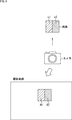
- FIG. 8 is a diagram for explaining the presence / absence of occurrence of predetermined two colors.
- hue distance DF for example, the difference in the average value of hues (difference absolute value) in Equation (1) is adopted.
- one color c1 and the other color c2 of two predetermined colors c1 and c2 having different hues are attached to two adjacent areas, for example, the same degree as the anti-air sign 10
- a size sign is photographed with a camera to obtain a photographed image in which the sign is reflected.
- Shooting of the captured image on which the sign is reflected can be performed at a distance similar to that in the case of performing the aerial shooting of the anti-air marker 10, for example.
- the sign (region) is detected from the photographed image in which the sign is reflected, and the area A1 to which the color c1 is attached (estimated to be attached) and the area to which the color c2 is attached from the sign Specify A2.
- the hue distance DF of each of the areas A1 and A2 is calculated according to the equation (1) using the pixel values of the respective pixels of the areas A1 and A2.
- the colors c1 and c2 are assumed to be two colors that are likely to be mixed colors (prone to occur), and the two colors are not adopted as the colors of the circles 11 and 12. can do.
- the colors c1 and c2 can be adopted as the colors of the circles 11 and 12 as two colors that do not generate (are unlikely to be mixed). .
- the threshold value TH of the distance DF for example, the threshold value TH represented by the equation (3) can be adopted.
- H 1 is the hue of the pixel in the region to which the color c1 appears in the captured image obtained when close-up shooting (for example, shooting at the shortest focusing distance) of the color c1 alone is performed.
- H 2 is reflected in the photographed image obtained when performing color c2 single close-up photography, represents the average value of the hue of the pixel color c2 is attached region.
- the theoretical hues of the colors c1 and c2 for example, the average values of the hues of the pixels in the areas marked with the colors c1 and c2 that appear in the captured image obtained when close-up shooting is performed. Is done. Therefore, the theoretical hues of the colors c1 and c2 can also be adopted as H 1 and H 2 .
- the hue distance DF is 0.5 times or more of the hue difference
- the colors c1 and c2 are It can be adopted as 12 colors (colors).
- the anti-air sign 10 of the anti-air sign 10 caused by the color mixture of the colors attached to the adjacent circles 11 and 12 is used. A decrease in detection accuracy can be suppressed and the anti-air marker 10 can be detected with high accuracy.
- the detection accuracy of the anti-air marker 10 can be further improved as compared with the case where only the two colors having the distance DF equal to or greater than the threshold TH are used as the colors 11 and 12.
- rectangular areas are used as the areas A1 and A2.
- circular areas similar to the circles 11 and 12 may be used as the areas A1 and A2, respectively. it can.
- FIG. 9 is a block diagram showing a configuration example of computer hardware as the cloud server 30 of FIG.
- the cloud server 30 includes a CPU (Central Processing Unit) 32, and an input / output interface 40 is connected to the CPU 32 via the bus 31.
- CPU Central Processing Unit
- the CPU 32 When a command is input by operating the input unit 37 by a user (operator) or the like via the input / output interface 40, the CPU 32 stores the instruction in a ROM (Read Only Memory) 33 accordingly. Run the program. Alternatively, the CPU 32 loads a program stored in the hard disk 35 into a RAM (Random Access Memory) 34 and executes it.
- the CPU 32 is configured by one or a plurality of processing circuits.
- the CPU 32 performs various processes and causes the cloud server 30 to function as a device having a predetermined function. Then, the CPU 32 outputs the processing results of various processes as needed, for example, via the input / output interface 40, from the output unit 36, or from the communication unit 38, and further recorded in the hard disk 35.
- the input unit 37 includes a keyboard, a mouse, a microphone, and the like.
- the output unit 36 includes an LCD, a speaker, and the like.
- the program executed by the CPU 32 can be recorded in advance in a hard disk 35 or ROM 33 as a recording medium built in the cloud server 30.
- the program can be stored (recorded) in the removable recording medium 41.
- a removable recording medium 41 can be provided as so-called package software.
- examples of the removable recording medium 41 include a flexible disk, a CD-ROM (Compact Disc Read Only Memory), an MO (Magneto Optical) disc, a DVD (Digital Versatile Disc), a magnetic disc, a semiconductor memory, and the like.
- the program can be downloaded to the cloud server 30 via a communication network or a broadcast network and installed in the built-in hard disk 35. That is, for example, the program is wirelessly transferred from the download site to the cloud server 30 via a digital satellite broadcasting artificial satellite, or to the cloud server 30 via a network such as a LAN (Local Area Network) or the Internet. It can be transferred by wire.
- a communication network or a broadcast network installed in the built-in hard disk 35. That is, for example, the program is wirelessly transferred from the download site to the cloud server 30 via a digital satellite broadcasting artificial satellite, or to the cloud server 30 via a network such as a LAN (Local Area Network) or the Internet. It can be transferred by wire.
- LAN Local Area Network
- the CPU 32 causes the cloud server 30 to function as a device having a predetermined function by executing a program.
- the CPU 32 causes the cloud server 30 to function as an image processing apparatus that performs image processing of a captured image from the camera 21.
- the cloud server 30 as the image processing apparatus performs a detection process for detecting the anti-air sign 10 shown in the captured image. Therefore, it can also be said that the cloud server 30 is a detection device that performs such detection processing.
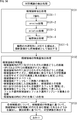
- FIG. 10 is a block diagram illustrating a functional configuration example of the cloud server 30 that functions as the image processing apparatus (detection apparatus) as described above.
- the cloud server 30 includes a candidate area extraction unit 61, a feature amount extraction unit 62, and an identification unit 63.
- the candidate area extraction unit 61, the feature amount extraction unit 62, and the identification unit 63 are configured by the CPU 32 of FIG. 9, for example.
- the captured image from the camera is supplied to the candidate area extraction unit 61 and the identification unit 63.
- the candidate area extraction unit 61 extracts candidate areas that are candidates for the area in which the anti-air marker 10 (circle 12) appears from the captured image obtained by capturing the anti-air sign 10 from the camera 21 and supplies the candidate area to the feature amount extraction unit 62. To do.
- the feature amount extraction unit 62 extracts the feature amount of the candidate region from the candidate region from the candidate region extraction unit 61 and supplies it to the identification unit 63.
- the identification unit 63 identifies the anti-air marker 10 (the circle 12) (the region in which the image is displayed) reflected in the captured image based on the feature amount of the candidate region from the feature amount extraction unit 62.
- the identification unit 63 identifies whether or not the candidate area is the anti-air mark 10 based on the feature amount of the candidate area.
- the identification unit 63 detects the anti-air marker 10 from the captured image from the camera 21 based on the identification result of the anti-air marker 10, and the detection result (for example, the image of the anti-air marker 10 or the anti-air marker in the captured image). 10 position).
- FIG. 11 is a flowchart illustrating an example of a detection process for detecting the anti-air sign 10 performed by the CPU 32 of the cloud server 30 as the image processing apparatus of FIG.
- step S31 the candidate area extraction unit 61 performs a candidate area extraction process for extracting a candidate area from the captured image from the camera 21.
- the candidate area extraction unit 61 determines whether the pixel is a color pixel attached to the circle 12 of the anti-air marker 10 or a pixel other than the color. Each pixel (pixel value) of the captured image is binarized.
- the candidate area extraction unit 61 uses the hue H (Hue) of the red HSV space that is the color of the circle 12 as a red color.
- H Hue
- a pixel having a hue H in the range of 320 to 360 (degrees) is determined to be a pixel of the color attached to the circle 12, and the pixel value is set to one of 0 and 1 For example, set to 1.
- the candidate area extraction unit 61 does not select pixels other than the range of the hue H from 320 to 360 (pixels that are not determined to be pixels of the color attached to the circle 12) as pixels of the color attached to the circle 12. It is determined that the pixel is a pixel, and the pixel value is set to 0 which is the other of 0 and 1.
- the binarization of the pixel of the photographed image can be performed using not only the hue H of the HSV space of the color of the circle 12 but also the saturation S (Saturation) and the brightness (luminance) V (Value). .
- pixels having a hue H in the HSV space in the range of 320 to 360 and a saturation S in the range of 30 to 255 are represented by the circle 12 It can be determined that the pixel is a color pixel attached to.
- a pixel whose hue H in the HSV space is in the range of 320 to 360, saturation S is in the range of 30 to 255, and brightness V is in the range of 50 to 255 is the color of the color attached to the circle 12. It can be determined that it is a pixel.
- binarization for extracting a candidate area can be performed using at least the hue of the hue, saturation, and brightness of the color of the circle 12. .
- the anti-air mark 10 is reflected by performing binarization for extracting the candidate area by using at least the hue of the saturation or brightness in addition to the hue of the circle 12. As a region, a more probable candidate region is extracted, and as a result, the detection accuracy of the anti-air marker 10 can be improved.
- the candidate area extraction unit 61 performs binarized image erosion processing (erosion processing) obtained by binarization of the captured image to suppress binarized image noise. To do.
- the candidate area extraction unit 61 performs a dilation process (expansion process) on the binarized image after the erosion process.
- the candidate area extraction unit 61 determines that the pixel area having a pixel value of 1 in the binarized image after the dilation process, that is, Contour detection processing is performed to detect the contour of the pixel region estimated to be 12.
- the candidate area extraction unit 61 extracts an area corresponding to the smallest rectangle circumscribing the outline detected by the outline detection process as a candidate area from the captured image. This is supplied to the feature quantity extraction unit 62.
- candidate areas are extracted for each of the plurality of contours.
- step S32 the feature amount extraction unit 62 performs a feature amount extraction process for extracting the feature amount of each candidate region from the candidate region extraction unit 61, and obtains candidate regions obtained by the feature amount extraction process.
- the feature amount is supplied to the identification unit 63.
- the feature quantity extraction unit 62 can extract, for example, the feature quantities of the following candidate areas in the feature quantity extraction process.
- the feature amount extraction unit 62 estimates, for example, the size of the candidate region and the size of the anti-air marker 10 (the circle 12 thereof) when the anti-air marker 10 is reflected in the captured image.
- a ratio to the estimated size (hereinafter also referred to as a size ratio) can be obtained.
- the captured image captured by the camera 21 is recorded in a file in, for example, EXIF (Exchangeable Image File Format) format.
- EXIF Exchangeable Image File Format
- GPS information such as shooting date / time, focal length, latitude of shooting position, longitude, altitude (altitude), etc. is recorded as shooting metadata.
- the feature amount extraction unit 62 estimates the size of the anti-air marker 10 when the anti-air marker 10 is shown in the captured image, for example, from the altitude and focal length of the imaging position recorded in the EXIF format file.
- the size ratio it is possible to suppress identification of a candidate area that is too large or too small as an anti-air mark 10 (the area of the circle 12). For example, the closer the size ratio is to 1.0, the easier it is for the candidate area to be identified as the anti-air mark 10 (its circle 12).
- the feature quantity extraction unit 62 can obtain, for example, the aspect ratio of the candidate area as the feature quantity of the candidate area.
- the aspect ratio of the candidate area it is possible to suppress the identification of the horizontally or vertically candidate area as the anti-air mark 10. For example, as the aspect ratio of the candidate area is closer to 1.0, the candidate area is more easily identified by the anti-air mark 10.
- the feature quantity extraction unit 62 can obtain, for example, the correlation (similarity) between the candidate area and the template image of the anti-air traffic sign 10 (circles 11 and 12) as the feature quantity of the candidate area. For example, as the correlation between the candidate area and the template image is larger (there is a correlation), the candidate area is more easily identified by the anti-air marker 10.
- a template image of the anti-air sign 10 is prepared in advance.
- the correlation for example, a correlation coefficient, an average value of the sum of squares of differences, or the like can be adopted.
- the feature amount extraction unit 62 can obtain, for example, a correlation between a candidate region and a rotated image obtained by rotating the candidate region as the feature amount of the candidate region. The larger the correlation between the candidate area and the rotated image, the easier it is for the candidate area to be identified by the anti-air mark 10.
- the anti-air mark 10 has symmetry because the circles 11 to 13 are arranged concentrically.
- the symmetry of the anti-air marker 10 is used to identify the anti-air marker 10. Identification accuracy can be improved.
- the rotation of the candidate image when obtaining the rotated image is performed by a predetermined angle other than an integer multiple of 2 ⁇ .
- the feature quantity extraction unit 62 applies a filter (function) that emphasizes the colors attached to the circles 11 and 12 to the candidate area and the template image, and the candidate area and the template after the application of the filter are applied.
- the correlation with the image can be obtained as the feature amount of the candidate area. For example, as the correlation between the candidate area after applying the filter and the template image is larger, the candidate area is more easily identified by the anti-air marker 10.
- a filter to be applied to the candidate region and the template image for example, only the color attached to one of the circles 11 and 12 in addition to the filter that emphasizes the color attached to the circles 11 and 12.
- a filter or the like that emphasizes can be employed.
- the feature amount extraction unit 62 can obtain the hue distance of each of the circles 11 and 12 as the feature amount of the candidate area.
- the feature amount extraction unit 62 assumes that the candidate region is a region circumscribing the circle 12, and uses the hues of the pixels in which the circles 11 and 12 that would exist in the candidate region are used in FIG.
- the hue distance of each of the circles 11 and 12 described, for example, the distance DF of the equation (1) can be obtained as the feature amount of the candidate region.
- the candidate region is easily identified by the anti-air mark 10.
- step S ⁇ b> 33 the identification unit 63 displays, for each candidate region, an anti-air marker 10 (circle 12) (in the circle 12) (in the captured image) from the captured image based on the feature amount of the candidate region from the feature amount extraction unit 62. Area).
- the identification unit 63 identifies whether or not the candidate area is the anti-air mark 10 based on the feature amount of the candidate area.
- the identifying unit 63 detects the anti-air marker 10 from the photographed image from the camera 21 based on the identification result, and outputs the detection result.
- a three-dimensional model on the ground is created using the detection result of the anti-air sign 10 obtained as described above.
- each feature amount of the candidate area is threshold-processed, and it is identified whether the candidate area is the anti-air mark 10 by majority decision of the processing result of the threshold process, weighted addition of points indicating the process result, or the like. Can do.
- each feature quantity of the candidate area is input to a classifier configured by a neural network or the like that has been learned in advance, and the candidate area is the anti-air marker 10 based on the output of the classifier in response to the input. Whether it can be identified.
- the feature amount of the candidate area extracted by the feature amount extraction unit 62 is not limited to the above-described feature amount.
- the anti-air marker 10 can be detected with higher accuracy by including the distances DF of the hues of the circles 11 and 12 in the feature amount of the candidate region.
- the candidate area extraction unit 61 detects (binarizes for) the candidate area using at least the hue of the circle 12, so for example, red It is possible that an area in which the pylon is shown is extracted as a candidate area. In this case, if the feature amount of the candidate area does not include the hue distance DF of each of the circles 11 and 12, there is a high possibility that the candidate area in which the pylon appears is erroneously identified as the anti-air marker 10.
- the cylindrical member 11 of the anti-air sign 10 includes an illuminance detection device that detects the illuminance of the anti-air mark 10, a communication device that performs wireless communication, and the like, the cloud server 30
- the detection process of FIG. 11 can be performed using the illuminance information regarding the illuminance of the anti-air sign 10 detected by the illuminance detection device (the distribution of the illuminance (luminance) of the anti-air sign 10) detected from the anti-air sign 10.
- the candidate area extraction unit 61 can extract a candidate area using illuminance information.
- the candidate area extraction unit 61 uses the illuminance information to estimate the hue, saturation, and lightness range of the circle 12 of the anti-air marker 10 that appears in the captured image, and the hue or saturation within the range. It is possible to determine that the pixel having the brightness and the brightness is a pixel in which the circle 12 is reflected, and to extract (binarize for) the candidate area.
- the identification unit 63 can identify the anti-air sign 10 using the illuminance information.
- the identifying unit 63 compares the hue distance DF of each of the circles 11 and 12 as the feature amount of the candidate region with the threshold value TH of the expression (3), and based on the comparison result, When the distance DF is greater than or equal to the threshold value TH, the possibility of identifying that the candidate area is the anti-air marker 10 can be increased, and the anti-air marker 10 can be identified.
- the identification unit 63 can set the threshold TH used for the identification of the anti-air sign 10 as described above using the illuminance information.
- the identification unit 63 estimates the hue of each pixel of the circles 11 and 12 obtained when the anti-air marker 10 is photographed under the illuminance condition represented by the illuminance information, and the circles 11 and 12 obtained by the estimation
- the average value of the hue (estimated value) of each pixel can be used as H 1 and H 2 in Expression (3) to set the threshold value TH in Expression (3).
- the detection accuracy of the anti-air marker 10 can be improved by extracting candidate areas and identifying the anti-air marker 10 by using the illuminance information of the anti-air marker 10 detected by the illuminance detection device. it can.
- FIG. 12 is a flowchart for explaining an example of detailed processing of binarization of each pixel of the captured image performed in step S31-1 in FIG.
- step S51 the candidate area extraction unit 61 selects one of the pixels of the captured image that has not yet been selected as the target pixel, as the target pixel, and the process proceeds to step S52.
- step S52 the candidate area extraction unit 61 obtains the hue H of the target pixel by obtaining it, and the process proceeds to step S53.
- step S53 the candidate area extraction unit 61 determines whether or not the hue H of the target pixel can be regarded as the hue of the color of the circle 12, that is, the hue H of the target pixel satisfies the expressions ⁇ ⁇ H and H ⁇ . Determine if it meets.
- ⁇ and ⁇ represent the minimum value and the maximum value of the range that can be regarded as the hue of the color of the circle 12, respectively.
- step S53 If it is determined in step S53 that the hue H of the target pixel satisfies the expressions ⁇ ⁇ H and H ⁇ , the process proceeds to step S54.
- step S54 the candidate area extraction unit 61 assumes that the pixel of interest is a pixel of the hue of the circle 12, sets the pixel value of the pixel of interest to 1 indicating that the pixel of the circle 12 has a hue, The process proceeds to step S56.
- Step S53 when it is determined that the hue H of the target pixel does not satisfy at least one of Expression ⁇ ⁇ H and Expression H ⁇ , the process proceeds to Step S55.
- the candidate area extraction unit 61 sets the pixel value of the target pixel to 0 indicating that the pixel of interest is not a pixel of the hue of the circle 12, assuming that the pixel of interest is not a pixel of the hue of the circle 12, and Proceed to S56.
- step S56 the candidate area extraction unit 61 determines whether all the pixels of the captured image have been selected as the target pixel.
- step S56 If it is determined in step S56 that all the pixels of the captured image have not yet been selected as the target pixel, the process returns to step S51.
- step S51 the candidate area extraction unit 61 newly selects one of the pixels of the captured image that has not yet been selected as the pixel of interest as the pixel of interest, and thereafter the same processing is repeated. .
- step S56 If it is determined in step S56 that all the pixels of the captured image have been selected as the target pixel, the binarization process ends.
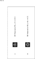
- FIG. 13 is a diagram illustrating an example of a template image of the anti-air marker 10 (circles 11 and 12) used by the feature amount extraction unit 62 to extract feature amounts of candidate areas.
- Gaussian function defined by the coefficients a, ⁇ , and ⁇ is expressed as Gaussian (a, ⁇ , ⁇ ) as shown in Equation (4).
- an image defined by a Gaussian function shown in FIG. 13 can be employed as the template image.
- FIG. 13A shows a first example of a template image
- FIG. 13B shows a second example of a template image.
- Equation (4) the hue as the pixel value of the template image is represented by y, and the variable x of the Gaussian function Gaussian (a, ⁇ , ⁇ ) in Equation (4) represents the distance from the center of the template image.
- FIG. 14 is a diagram illustrating an example of a filter used when emphasizing the colors attached to the circles 11 and 12 of the candidate region and the template image in the feature amount extraction processing in step S32 of FIG.
- the filter that emphasizes the colors attached to the circle 11 is a blue filter that emphasizes blue and is attached to the circle 12.
- the filter that emphasizes the color is a red filter that emphasizes red.
- Equation (4) the hue input to the filter.
- the solid line represents the input / output characteristics of the red filter
- the dotted line represents the input / output characteristics of the blue filter.
- an image P1 is a candidate area in which a circle 12 appears, and the candidate area adopting the hue H as a pixel value is resized to 50 ⁇ 50 pixels in the horizontal and vertical directions, and the center 30 ⁇ 30 It is the image which extracted the pixel.
- the image Q1 is a candidate area where the circle 12 is not reflected, and the candidate area adopting the hue H as the pixel value is resized to 50 ⁇ 50 pixels, and the center 30 ⁇ 30 pixels are extracted. is there.
- the images P2 and Q2 are images obtained by applying a blue filter to the images P1 and Q1, respectively, and the images P3 and Q3 are images obtained by applying a red filter to the images P1 and Q1, respectively.
- FIG. 15 is a flowchart for explaining an example of processing for extracting the hue distance DF of each of the circles 11 and 12 as the feature amount in the feature amount extraction processing performed in step S32 of FIG.
- step S71 the feature amount extraction unit 62 assumes that the candidate region is a region circumscribing the circle 12, and pixels (pixels that should be reflected) in which each of the circles 11 and 12 existing in the candidate region appears.
- each of them is also referred to as a pixel in the region of the circle 11 and a pixel in the region of the circle 12), and the process proceeds to step S72.
- step S72 the feature amount extraction unit 62 obtains the hue H of each pixel in the region of the circle 11 by obtaining the hue H and obtains the hue H of each pixel in the region of the circle 12, and the processing is performed in step S72. Proceed to S73.
- step S73 the feature quantity extraction unit 62 follows the equation (1) and calculates the average value of the hue H of each pixel in the region of the circle 11 ( ⁇ H i, j / N1 in the first term on the right side of the equation (1)) and the circle.
- the difference absolute value with respect to the average value of hue H of each pixel in the 12 regions ( ⁇ H i, j / N2 in the second term on the right side of the equation (1)) is obtained as the hue distance DF of each of the circles 11 and 12 and processed. Ends.
- a single circular sign shown in FIG. 4 and a plurality of circular signs shown in FIGS. 5 and 6 are installed in a mixed manner, and the single circular sign is detected with sufficient accuracy. If it is possible to detect a single circular marker without detecting multiple circular markers, and if it is not possible to detect a single circular marker with sufficient accuracy, Label detection can be performed.
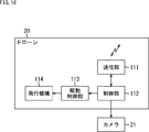
- FIG. 16 is a block diagram showing a configuration example of the drone 20 of FIG.
- the drone 20 includes a communication unit 111, a control unit 112, a drive control unit 113, and a flight mechanism 114.
- the communication unit 111 performs wireless or wired communication with the cloud server 30, a controller (proportional control system) (not shown) that controls the drone 20, and other arbitrary devices under the control of the control unit 112.
- the control unit 112 includes a CPU, a memory, and the like (not shown), and controls the communication unit 111, the drive control unit 113, and the camera 21.
- control unit 112 causes the communication unit 111 to transmit a captured image captured by the camera 21.
- the drive control unit 113 controls the driving of the flight mechanism 114 according to the control of the control unit 112.
- the flight mechanism 114 is a mechanism for flying the drone 20, and includes, for example, a motor and a propeller (not shown).
- the flight mechanism 114 is driven according to the control of the drive control unit 113 and causes the drone 20 to fly.
- the control unit 112 drives the flight mechanism 114 by controlling the drive control unit 113 according to the signal from the proportional control system received by the communication unit 111, for example. . Thereby, the drone 20 flies according to the operation of the proportional control system.
- control unit 112 controls the camera 21 in accordance with a signal from the proportional control system, and performs shooting.
- a captured image obtained by photographing with the camera 21 is transmitted from the communication unit 111 via the control unit 112.
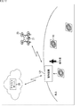
- FIG. 17 is a diagram illustrating an outline of another embodiment of the soil amount measurement system to which the present technology is applied.
- the soil volume measurement system in FIG. 17 includes an anti-air sign 10, a drone 20, a cloud server 30, and a control device 121.
- the soil volume measurement system of FIG. 17 is different from the case of FIG. 1 in that a control device 121 is newly provided.
- the control device 121 is composed of a dedicated device that functions as a GCS (Ground Control Station) (Ground Control Station).
- the control device 121 is configured by a device having a communication function such as a PC (Personal Computer), a tablet, or a smartphone executing a program for causing such a device to function as a GCS.
- the control device 121 communicates with the drone 20 in accordance with the operation of the operator, controls the flight of the drone 20, acquires the position, takes a command for the camera 21 mounted on the drone 20, and takes a picture taken by the camera 21. Gives an image acquisition command.
- the control device 121 performs detection processing for detecting the anti-air marker 10 (image thereof) from the photographed image acquired from the drone 20 in accordance with the operation of the operator, and displays the detection result of the anti-air marker 10 obtained by the detection processing. be able to. The operator can confirm from the detection result of the anti-air mark 10 whether the anti-air mark 10 has been properly captured.
- the operator When shooting of the anti-air sign 10 is not properly performed, for example, when the anti-air mark 10 cannot be detected by the detection process, the operator operates the control device 121 to fly the drone 20 again. The anti-air mark 10 can be photographed.
- the control device 121 can upload the captured image acquired from the drone 20 to the cloud server 30.
- the anti-air sign 10 includes an illuminance detection device and transmits illuminance information detected by the illuminance detection device
- the illuminance information is stored in the control device 121. Can be received.
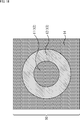
- FIG. 18 is a plan view showing a first modification of the anti-air sign 10 of a multi-circular sign.
- the anti-air sign 10 of FIG. 18 is composed of circles 11 and 12 (or circles 12 and 13) and a frame region 14, and the circle 13 (or circle 11) is not provided for the anti-air mark 10 of FIG. It has a configuration.
- the anti-air sign 10 of FIG. 18 has a configuration in which a frame region 14 is provided with respect to the anti-air sign 10 of FIG. 5C (or D).
- achromatic black chromatic red, and achromatic black can be employed, respectively.
- FIG. 19 is a perspective view showing a second modification of the anti-air mark 10 of a multi-circular sign.
- 19 is, for example, a cylindrical member 201 having a predetermined height (thickness) to be a circle 11, a substantially annular member 202 having a predetermined height to be a circle 12, and a circle 13. It is comprised by the substantially annular member 203 of predetermined height.
- the heights of the members 201 to 203 are the same.
- the member 202 has a substantially annular shape in which a central portion of a cylinder having a predetermined height is hollowed out into a cylindrical shape, and the cylindrical member 201 is fitted into a hollow portion of the member 202 cut out into a cylindrical shape. ing.
- the member 203 has a substantially annular shape in which a central portion of a cylinder having a predetermined height is hollowed out in a cylindrical shape, and the substantially annular member 202 is formed in the hollow portion of the member 203 that is hollowed in a cylindrical shape. It is inserted.
- the inside of the member 201, 202, or 203 is configured as a cavity, and the illuminance detection device described in FIG. 6 and the like can be incorporated in the member 201, 202, or 203. .
- the illuminance detection device and the like can be built in a plurality of members 201 to 203.
- the height (thickness) of the columnar member that becomes the circle 11 protrudes compared to the circular member that becomes the circle 12 and the circular member that becomes the circle 13. Therefore, depending on the direction of sunlight, the shadow of the columnar member that becomes the circle 11 may be greatly formed on the circle 12, and the detection accuracy of the anti-air marker 10 may deteriorate.
- the anti-air sign 10 of FIG. 19 is composed of a cylindrical member 201 and substantially annular members 202 and 203.
- the anti-air sign 10 has a circle 11 or a circle on the upper surface of a cylindrical member having a predetermined height. It can be configured by coloring to be 13.
- the anti-air marker 10 of FIG. 19 is colored, for example, on a circular cylindrical member 203 having a predetermined height, and the member is fitted into a substantially annular member 203. It can be configured by coloring the circles 12 and 13 on a substantially annular member and fitting the member 201 into the member.
- FIG. 20 is a perspective view showing a third modification of the anti-air sign 10 of a multi-circular sign.
- a predetermined height to be a circle 13 This is composed of a substantially annular member 213.
- the anti-air sign 10 of FIG. 20 differs from the case of FIG. 19 in that a member 213 is provided instead of the member 203.
- the member 213 is a substantially annular shape in which a central portion of a cylinder having a predetermined height is hollowed out in a columnar shape so as to leave the bottom plate 213A, or a central portion of a cylinder having a predetermined height is hollowed out in a cylindrical shape to form a bottom plate 213A. It has a substantially annular shape.
- the substantially annular member 202 is fitted into the hollow portion of the member 203 that is hollowed out in a columnar shape, and the cylindrical member 201 can be attached to and detached from the hollow portion of the member 202 that is hollowed out into a cylindrical shape. It is configured.
- the bottom plate 213A has the same color as the member 201, that is, the bottom plate 213A exposed from the hollow portion of the member 202 functions as the circle 11 in the anti-air marking 10 with the columnar member 201 removed.
- the color is achromatic black.
- the depth of the hollow portion of the member 213 hollowed out in a columnar shape is the same as the height of the members 201 and 202. Therefore, when the member 202 (and the member 201) is fitted in the hollow portion of the member 213, the upper surface of the anti-air marker 10 becomes a flat surface.
- the inside of the member 201 is configured as a cavity, and the illuminance detection device described with reference to FIG.
- the anti-air marker 10 can be used by attaching the cylindrical member 201 to the hollow portion of the member 202 that is hollowed out in a cylindrical shape.
- the columnar member 201 can be removed from the anti-air sign 10 and the anti-air sign 10 can be used.
- a shadow of the member 202 can be formed on the exposed bottom plate 213A.
- the color of the bottom plate 213A is black, the exposed bottom plate 213A has a black color.
- the shadow of the member 202 that can be formed does not (almost) affect the detection accuracy of the anti-air marker 10.
- the members 202 and 213 in FIG. 20 are hollowed out so that the member 201 can be attached to and detached from, for example, a central portion of one cylindrical member having a predetermined height, leaving a bottom plate 213A.
- Such a member can be configured by coloring the circle 11 to the circle 13.
- FIG. 21 is a perspective view showing a fourth modification of the anti-air sign 10 of a multi-circular sign.
- 21 is composed of a member 202 and a member 213.
- the anti-air sign 10 of FIG. 21 is configured in the same manner as in FIG. 20 except that the detachable member 201 is not provided.
- the inside of the member 202 or 213 is configured as a hollow, and the illuminance detection device described with reference to FIG. 6 and the like can be incorporated in the member 202 or 213.
- the illuminance detection device or the like can be built in over the members 202 and 213.
- the shadow of the member 202 can be formed on the exposed bottom plate 213A in the same manner as the anti-air marker 10 with the columnar member 201 removed in FIG. 20, but here, the bottom plate 213A is formed.
- the shade of the member 202 that can be formed on the exposed bottom plate 213A does not affect the detection accuracy of the anti-air marker 10.
- FIG. 22 is a perspective view showing a fifth modification of the anti-air sign 10 of a multi-circular sign.
- the anti-air sign 10 of FIG. 22 is configured in the same manner as in FIG. 19 except that a member 223 is provided instead of the member 203.
- the air-air marker 10 of FIG. 22 is configured such that the member 201 is fitted into the member 202, and the member 202 into which the member 201 is fitted (or one columnar member configured as the circles 11 and 12) is attached to the member 223. Consists of overlapping.
- the inside of the member 201 or 202 is configured as a cavity, and the illuminance detection device described with reference to FIG. 6 or the like can be incorporated in the member 201 or 202.
- the illuminance detection device or the like can be built in the members 201 and 202.
- the shadow of the member 202 can be formed on the member 223.
- the color of the member 223 that becomes the circle 13 is black, the member 202 that can be formed on the member 223 The shadow does not affect the detection accuracy of the anti-air mark 10.
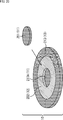
- FIG. 23 is a perspective view showing a sixth modification of the anti-air sign 10 of a multi-circular sign.
- the member 201 is configured to be attachable to and detachable from the hollow portion of the member 202 cut out in a columnar shape.
- the circular portion 223A as a part of the member 223 is exposed from the hollow portion, but the circular portion 223A functions as the circle 11.
- the color is the same as that of the member 201, that is, an achromatic black here.
- the member 201 has a hollow interior, and the illuminance detection device described with reference to FIG. 6 and the like can be incorporated in the member 201.
- the anti-air marker 10 can be used by attaching the cylindrical member 201 to the hollow portion of the member 202 that is hollowed out in a cylindrical shape.
- the columnar member 201 can be removed from the anti-air sign 10 and the anti-air sign 10 can be used.
- a shadow of the member 202 can be formed on the exposed circular portion 223A. Regardless of whether the member 201 is attached or detached, the shadow of the member 202 can be formed on the member 223.
- the color of the member 223 including the circular portion 223A is black here, the shadow of the member 202 that can be formed on the member 223 including the circular portion 223A does not affect the detection accuracy of the anti-air sign 10.
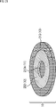
- FIG. 24 is a perspective view showing a seventh modification of the anti-air mark 10 of a multi-circular sign.
- the member 202 has a hollow interior, and the illuminance detection device described with reference to FIG. 6 and the like can be incorporated in the member 202.
- the shadow of the member 202 can be formed on the circular portion 223A or the member 223, as in the case of FIG. 23, but the color of the member 223 including the circular portion 223A is black. The shadow of the member 202 does not affect the detection accuracy of the anti-air marker 10.
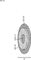
- FIG. 25 is a perspective view showing an eighth modification of the anti-air sign 10 of a multi-circular sign.
- the member 213 has a substantially circular shape in which a central portion of a cylinder having a predetermined height is hollowed out into a cylindrical shape leaving a bottom plate 213A, or a central portion of a cylinder having a predetermined height. It is hollow in a columnar shape and has a substantially annular shape with a bottom plate 213A.
- the bottom plate 213 ⁇ / b> A of the member 213 is colored so that the bottom plate 213 ⁇ / b> A functions as the circles 11 and 12. That is, here, the circular area at the center of the bottom plate 213A is black so that it functions as the circle 11, and the area around the circle is red so that it functions as the circle 12. Yes.
- the member 213 (the portion that functions as the circle 13) has a hollow interior, and the illuminance detection device described with reference to FIG. 6 and the like can be incorporated in the member 213.
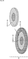
- FIG. 26 is a perspective view showing a ninth modification of the anti-air marking 10 of a multi-circular sign.
- 26 is composed of a columnar member 231 and a member 213 having a predetermined height to be circles 11 and 12.
- the member 231 has, for example, the same shape (columnar shape) as the member 202 into which the member 201 of FIG. 19 is fitted. Further, the member 231 is colored to be the circles 11 and 12 so that the member 231 functions as the circles 11 and 12.
- the member 231 is detachable from the hollow portion of the member 213.
- the inside of the member 231 is configured as a cavity, and the illuminance detection device and the like described in FIG. 6 and the like can be incorporated in the member 231.
- the member 231 can be attached to the hollow portion of the member 213 and the anti-air marker 10 can be used.
- the member 231 can be removed from the anti-air sign 10 and the anti-air sign 10 can be used.
- the member 231 can be composed of, for example, the members 201 and 202 in FIG.
- FIG. 27 is a perspective view showing a tenth modification of the anti-air sign 10 of a multi-circular sign.
- 27 is configured by, for example, stacking the member 201 on the area of the bottom plate 213A of the member 213 that is to be the circle 11.
- the inside of the member 201 or the member 213 (the portion that functions as the circle 13) is formed as a hollow, and the illuminance detection device or the like described in FIG. be able to.
- the members 201 and 213 can be formed as cavities, and an illuminance detection device or the like can be incorporated in the members 201 and 213 separately.
- the anti-air marking 10 in which the circles 11 and 13 have a certain thickness is not limited to the above-described configuration. That is, the anti-air marking 10 in which the circles 11 and 13 have a certain thickness can be configured such that one or both of the part that becomes the circle 11 and the part that becomes the circle 13 can be attached and detached.
- FIG. 28 is a perspective view showing an eleventh modification of the anti-air sign 10 of a multi-circular sign.
- a circle 11 to a circle 13 are drawn on the upper surface of the member 250 by printing or the like.
- the member 250 can be made of, for example, a translucent material such as white, and the inside can be made hollow.
- the member 250 can incorporate, for example, a lighting device (not shown).
- the anti-air mark 10 can be caused to emit light by turning on the lighting device.
- the anti-air sign 10 By emitting the anti-air sign 10, it is possible to shoot in a state where the anti-air sign 10 can be detected even in a dark situation such as at night, or the anti-air sign 10 can be used as a landmark when landing the drone 20. .
- FIG. 29 is a plan view showing a twelfth modification of the anti-air sign 10 of a multi-circular sign.
- a red circle 12 portion and a white frame region 14 portion are formed of a light emitter such as an LED (Light Emitting Diode).
- a light emitter such as an LED (Light Emitting Diode).
- the red circle 12 and the white frame region 14 are illuminated so that the anti-air marker 10 can be photographed in a dark state such as at night, or the anti-air marker 10 can be captured by the drone 20. It can be used as a landmark when landing.
- FIG. 30 is a perspective view showing a thirteenth modification of the anti-air marking 10 of a multi-circular sign.
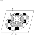
- the anti-air sign 10 of FIG. 30 has a design of the anti-air sign 10 drawn on a drone landing pad by printing or the like, and thus functions as an anti-air sign and also as a landing pad.
- the landing pad is used to prevent the sand on the ground from rolling up and entering the drone's motor, etc. when the drone is taking off and landing, and to clarify the landing location of the drone.
- the drone 20 can detect the position of the landing pad serving as the anti-air mark 10 from the captured image.
- the drone 20 takes into consideration the mounting position of the camera 21 so that the anti-air sign 10 reflected in the captured image taken by the camera 21 is always at a fixed position. By controlling the state, it is possible to take off and land vertically with respect to the anti-air sign 10, and the convenience of the landing pad that is the anti-air sign 10 can be enhanced.
- the anti-air sign 10 of FIG. 30 it is possible to recognize the change in the design of the anti-air sign 10 shown in the photographed image and the take-off and landing of the drone 20, and to record the time of take-off and landing. Such time can be used for automatic creation of reports such as soil volume measurement.
- the anti-air marker 10 has a planar shape in which a plurality of circles having different radii are concentrically arranged, and a marker having a different hue of adjacent circles among the plurality of circles is employed.
- a label having a planar shape in which a plurality of circles having different radii are concentrically arranged, and the luminance or hue of adjacent circles among the plurality of circles can be employed.
- “hue” can be read as “luminance or hue”.
- circles 11 to 13 circles having different luminance or hue of adjacent circles can be adopted.
- the luminance or hue of adjacent circles be different. Therefore, the luminance or hue of adjacent circles 11 and 12 are different, and the luminance or hue of adjacent circles 12 and 13 are different. Thus, the luminance or hue of the non-adjacent circles 11 and 13 may be the same.
- adjacent circles may differ only in luminance or hue, or both luminance and hue may differ.
- the detection of the anti-air mark 10 is performed using the distance of the brightness of each of the adjacent circles 11 and 12, and further using the distance of the hue as necessary, the color combinations of the circles 11 and 12 exist in nature. It is effective that the combination is as small as possible.
- the color combinations of the circles 11 and 12 are combinations in which the luminance or hue of each color is as different as possible.
- the combination of the colors of the circles 11 and 12 is a combination in which the degree of color mixing is as low as possible when shooting from a certain altitude, for example, the luminance or hue of the circle 11 obtained from the captured image and the luminance of the circle 12. Or it is effective that the distance to the hue is as large as possible.
- the distance between the peaks of the two distributions existing in the hue histogram may be employed as the hue distance between the circles 11 and 12. it can.
- the distance between the luminances of the circles 11 and 12 includes a distribution having a peak at the first luminance appearing in a luminance histogram for pixels of the circles 11 and 12 detected from the captured image, and a second value.
- the distance between the peaks of the two distributions (the difference in luminance between the peaks) can be adopted.
- the difference in the integrated values such as the average value of the hues of the pixels of the circles 11 and 12 detected from the captured image.
- the luminance distances of the circles 11 and 12 are similarly determined as the luminances of the pixels of the circles 11 and 12 detected from the captured image. Differences in integrated values such as average values can be employed.
- FIG. 31 is a diagram showing the HLS color space.
- the vertical axis represents the luminance L
- the vertical axis to the luminance L axis (hereinafter also referred to as the luminance axis) is on a two-dimensional plane
- the distance from the luminance axis represents the saturation S.
- the angle around the luminance axis represents the hue H.
- a point on the luminance axis represents an achromatic color.
- FIG. 32 is a diagram for explaining the outline of detection of the anti-air sign 10 using luminance.
- the image processing apparatus in FIG. 10 uses the distance (brightness difference) between each of the circles 11 and 12 (regions assumed (estimated)) of the anti-air signs 10 shown in the photographed image, from the candidate region to anti-air. It is possible to distinguish between the area of the sign 10 and the area that is not.
- the area of the anti-air marking 10 and the area other than the candidate area are compared with each other with relatively high accuracy using the luminance distance of each of the circles 11 and 12. Can be determined.
- the image processing apparatus of FIG. 10 uses the hue distances (hue differences) of the circles 11 and 12 of the anti-air marker 10 shown in the photographed image when the luminance distances of the circles 11 and 12 are small. From the candidate area, it is possible to discriminate between the area of the anti-air mark 10 and the other area.
- the image processing apparatus uses the distances of the 12 hues, the area of the anti-air mark 10 and the area that is not the area can be determined from the candidate areas.
- the detection of the anti-air mark 10 using the luminance is performed using the luminance distances of the adjacent circles 11 and 12, and further, the luminance distances of the adjacent circles 12 and 13 and the non-adjacent circles 11 and 13, respectively. Can also be performed using the distance of the brightness.
- FIG. 33 is a diagram for explaining an outline of detection of the anti-air sign 10 using luminance when the anti-air sign 10 has circles 11 to 13.
- the anti-air sign 10 When the anti-air sign 10 has circles 11 to 13, the luminance distance A of the circles 11 and 12, the luminance distance B of the circles 11 and 13, and the luminance distance C of the circles 12 and 13, respectively. It can be used to detect the anti-air marker 10.
- the anti-air marker 10 can be detected using the hue distances of the circles 12 and 13 respectively.
- FIG. 34 is a flowchart for explaining another example of the detection process for detecting the anti-air sign 10 performed by the CPU 32 of the cloud server 30 as the image processing apparatus of FIG.
- step S131 the candidate area extraction unit 61 performs a candidate area extraction process for extracting a candidate area from the captured image from the camera 21.
- the candidate area extraction unit 61 binarizes each pixel (its pixel value) to 1 or 0 depending on whether or not it is a pixel of the circle 12 of the anti-air marker 10. Turn into.
- the binarization in step S131-1 can be performed, for example, by performing threshold processing on the luminance and hue of the pixel.
- the candidate area extraction unit 61 performs erosion processing (erosion processing) of the binarized image obtained by binarizing the captured image, and suppresses noise of the binarized image. To do.
- the candidate area extraction unit 61 performs dilation processing (expansion processing) on the binarized image after erosion processing.
- step S131-4 the candidate area extraction unit 61 in the binarized image after the dilation process, for example, the area of the pixel whose pixel value is 1, that is, the captured image .
- a contour detection process is performed to detect the contour of the pixel region in which the circle 12 is estimated to be reflected.
- the candidate area extraction unit 61 extracts an area corresponding to the smallest rectangle circumscribing the outline detected by the outline detection process as a candidate area from the captured image. This is supplied to the feature quantity extraction unit 62.
- candidate areas are extracted for each of the plurality of contours.
- step S132 the feature amount extraction unit 62 performs feature amount extraction processing for extracting the feature amount of each candidate region from the candidate region extraction unit 61, and obtains candidate regions obtained by the feature amount extraction processing.
- the feature amount is supplied to the identification unit 63.
- the feature amount extraction unit 62 obtains, for example, the distance between the respective luminances of the circles 11 and 12 in the feature amount extraction process in step S132, in addition to the same feature amount as in step S32 in FIG.
- the feature amount extraction unit 62 obtains the brightness distance of each of the circles 11 and 12 instead of the hue distance of each of the circles 11 and 12, and the brightness distance is small. In some cases, the hue distances of the circles 11 and 12 are obtained.
- step S133 the identification unit 63 displays, for each candidate region, an anti-air marker 10 (a circle 12) (in the captured image) from the captured image based on the feature amount of the candidate region from the feature amount extraction unit 62. Area).
- the identification unit 63 identifies whether the candidate area is the anti-air marker 10 based on the feature amount of the candidate area, as in step S33 of FIG.
- the identifying unit 63 detects the anti-air marker 10 from the photographed image from the camera 21 based on the identification result, and outputs the detection result.
- step S133 when the distance between each of the circles 11 and 12 is large (when the distance is greater than or equal to the threshold), the identification unit 63 identifies whether the candidate region is the anti-air marker 10 or not. This can be done without using the distance of each of the 12 hues.
- step S133 the identification unit 63 determines whether the candidate area is the anti-air marker 10 when the distance between the luminances of the circles 11 and 12 is small (not large). Each color distance can be used.
- the anti-air marker 10 can be detected with higher accuracy by including the brightness and hue distance of each of the circles 11 and 12 in the feature amount of the candidate region.
- FIG. 35 is a flowchart for explaining an example of detailed processing of binarization of each pixel of the captured image performed in step S131-1 in FIG.
- a chromatic color for example, red
- luminance L and the hue H exist is used in order to easily distinguish the color from the natural world.
- step S151 the candidate area extraction unit 61 selects one of the pixels of the captured image that has not yet been selected as the target pixel, as the target pixel, and the process proceeds to step S152.
- step S152 the candidate area extraction unit 61 obtains the luminance L and hue H of the pixel of interest by obtaining the luminance, and the process proceeds to step S153.
- step S153 the candidate area extraction unit 61 determines whether the hue H of the target pixel can be regarded as the hue of the color of the circle 12, that is, the hue H of the target pixel satisfies the expressions ⁇ ⁇ H and H ⁇ . Determine if it meets.
- ⁇ and ⁇ represent a minimum value and a maximum value in a range that can be regarded as the hue of the color of the circle 12, and are set in advance.
- the candidate area extraction unit 61 determines whether the luminance L of the target pixel can be regarded as the luminance of the circle 12, that is, the luminance L of the target pixel satisfies the expressions ⁇ ⁇ H and H ⁇ . Determine if it meets.
- ⁇ and ⁇ represent a minimum value and a maximum value in a range that can be regarded as the luminance of the circle 12, and are set in advance.
- step S153 it is determined that the hue H of the target pixel satisfies Expression ⁇ ⁇ H and Expression H ⁇ , and the luminance L of the target pixel satisfies Expression ⁇ ⁇ H and Expression H ⁇ . If so, the process proceeds to step S154.
- step S154 the candidate area extraction unit 61 sets the pixel value of the target pixel to 1 indicating that the target pixel is a pixel of the luminance and hue of the circle 12, assuming that the target pixel is a pixel of the luminance and hue of the circle 12. Then, the process proceeds to step S156.
- step S153 the hue H of the target pixel does not satisfy at least one of the formula ⁇ ⁇ H and the formula H ⁇ , or the luminance L of the target pixel has the formula ⁇ ⁇ H and If it is determined that at least one of the expressions H ⁇ is not satisfied, the process proceeds to step S155.
- step S155 the candidate area extraction unit 61 sets the pixel value of the target pixel to 0 indicating that the target pixel is not the luminance and hue pixel of the circle 12, assuming that the target pixel is not the luminance and hue pixel of the circle 12. The process proceeds to step S156.
- step S156 the candidate area extraction unit 61 determines whether all pixels of the captured image have been selected as the target pixel.
- step S156 If it is determined in step S156 that all the pixels of the captured image have not yet been selected as the target pixel, the process returns to step S151.
- step S151 the candidate area extraction unit 61 newly selects one of the pixels of the captured image that has not yet been selected as the target pixel, as the target pixel, and thereafter the same processing is repeated. .
- step S156 If it is determined in step S156 that all the pixels of the captured image have been selected as the target pixel, the binarization process ends.
- FIG. 36 is a flowchart for explaining an example of processing for extracting the luminance distances of the circles 11 and 12 as feature amounts in the feature amount extraction processing performed in step S132 of FIG.
- step S171 the feature amount extraction unit 62 assumes that the candidate region is a region circumscribing the circle 12, and pixels (pixels that should be reflected) in which each of the circles 11 and 12 existing in the candidate region appears. The pixel in the region of the circle 11 and the pixel in the region of the circle 12) are detected, and the process proceeds to step S172.
- step S172 the feature amount extraction unit 62 obtains the luminance of each pixel in the area of the circle 11 by obtaining the luminance and obtains the luminance of each pixel in the area of the circle 12, and the process proceeds to step S173. move on.
- step S173 the feature amount extraction unit 62 calculates the absolute difference between the average value of the luminance of each pixel in the area of the circle 11 and the average value of the luminance of each pixel in the area of the circle 12, and The luminance distance is obtained, and the process ends.
- the detection of the anti-air sign 10 from the photographed image can be performed using one or both of the luminance and the hue distance between adjacent circles of the anti-air sign 10.
- the processing performed by the computer such as the cloud server 30 according to the program does not necessarily have to be performed in time series in the order described as the flowchart. That is, the processing performed by the computer according to the program includes processing executed in parallel or individually (for example, parallel processing or object processing).
- the program may be processed by one computer (processor), or may be distributedly processed by a plurality of computers. Furthermore, the program may be transferred to a remote computer and executed.
- the system means a set of a plurality of components (devices, modules (parts), etc.), and it does not matter whether all the components are in the same housing. Accordingly, a plurality of devices housed in separate housings and connected via a network and a single device housing a plurality of modules in one housing are all systems. .
- the present technology uses an aerial view of an anti-air sign other than the soil volume measurement system, for example, a building or the like.
- the present invention can be applied to a system that performs arbitrary measurement.
- the present technology can take a cloud computing configuration in which one function is shared by a plurality of devices via a network and is jointly processed.
- each step described in the above flowchart can be executed by one device or can be shared by a plurality of devices.
- the plurality of processes included in the one step can be executed by being shared by a plurality of apparatuses in addition to being executed by one apparatus.
- this technique can take the following structures.
- a plurality of circles have a planar shape arranged concentrically,
- a candidate area extraction unit that extracts candidate areas that are candidates for areas where the anti-air signs appear, from a captured image obtained by photographing the anti-air signs that have different brightness or hue of adjacent circles of the plurality of circles;
- a feature quantity extraction unit for extracting feature quantities of the candidate area;
- An image processing apparatus comprising: an identification unit that identifies the anti-aircraft sign based on the feature amount.
- the candidate region extraction unit extracts the candidate region using at least the hue of the hue, saturation, and brightness of the circle having the second smallest radius among the plurality of circles.
- the feature amount extraction unit extracts, as the feature amount, a distance between a luminance or hue of a circle having the smallest radius and a luminance or hue of a circle having the second smallest radius among the plurality of circles. ⁇ 1 > Or ⁇ 2>. ⁇ 4> The feature quantity extraction unit extracts, as the feature quantity, a correlation between the candidate area and a rotated image obtained by rotating the candidate area by a predetermined angle other than an integer multiple of 2 ⁇ . ⁇ 1> to ⁇ 3> The image processing apparatus according to any one of the above.
- the feature amount extraction unit applies a filter that emphasizes the color attached to the circle to the candidate area and the template image of the anti-air sign, and the candidate area and the template after the application of the filter
- the image processing apparatus according to any one of ⁇ 1> to ⁇ 4>, wherein a correlation with an image is extracted as the feature amount.
- the anti-air sign has a built-in detection device that acquires information on the anti-air sign,
- the image processing device according to any one of ⁇ 1> to ⁇ 5>, wherein the candidate region extraction unit extracts the candidate region using information regarding the anti-air sign detected by the detection device.
- the anti-air sign has a built-in illuminance detection device that detects illuminance
- the feature amount extraction unit extracts, as the feature amount, a distance between a luminance or hue of a circle having the smallest radius and a luminance or hue of a circle having the second smallest radius among the plurality of circles
- the identification unit compares the distance with a predetermined threshold, and based on the comparison result, the illuminance detection uses the predetermined threshold used to identify whether the candidate region is the anti-air marker.
- the image processing device according to any one of ⁇ 1> to ⁇ 6>, which is set using illuminance of the anti-air sign detected by the device.
- ⁇ 8> The image processing apparatus according to any one of ⁇ 1> to ⁇ 7>, wherein a three-dimensional model is created using the identification result of the anti-air sign.
- ⁇ 9> The image processing apparatus according to ⁇ 8>, wherein soil volume is measured from the three-dimensional model.
- a plurality of circles have a planar shape arranged concentrically, Extracting a candidate area that is a candidate for an area in which the anti-air mark appears from a captured image obtained by photographing an anti-air sign in which the brightness or hue of an adjacent circle of the plurality of circles is different; Extracting a feature amount of the candidate area;
- An image processing method comprising: identifying the anti-air sign based on the feature amount.
- a plurality of circles have a planar shape arranged concentrically, A candidate area extraction unit that extracts candidate areas that are candidates for areas where the anti-air signs appear, from a captured image obtained by photographing the anti-air signs that have different brightness or hue of adjacent circles of the plurality of circles; A feature quantity extraction unit for extracting feature quantities of the candidate area; A program for causing a computer to function as an identification unit that identifies the anti-air sign based on the feature amount.
- a plurality of circles having different radii have a planar shape arranged concentrically, An anti-air mark in which the brightness or hue of adjacent circles of the plurality of circles is different.
- the colors of two adjacent circles of the plurality of circles are the luminance or the hue of each of the two areas obtained from a photographed image obtained by photographing a marker attached to two areas where the colors of the two circles are adjacent.
- the anti-air marker according to any one of ⁇ 12> to ⁇ 14>, wherein the two distances are predetermined two colors that make a distance between them a predetermined threshold value or more.
- ⁇ 16> The anti-air marking according to ⁇ 15>, wherein colors of a circle having the smallest radius and a circle having the second smallest radius among the plurality of circles are the predetermined two colors.
- ⁇ 17> The anti-air marking according to ⁇ 16>, wherein an area of a portion of the circle having the second smallest radius excluding the circle having the smallest radius is approximately 1.0 to 3.0 times the area of the circle having the smallest radius.
- ⁇ 18> The anti-air sign according to any one of ⁇ 12> to ⁇ 17>, wherein the plurality of circles are arranged concentrically and have a planar shape in which a rectangle including the plurality of circles is arranged.
- ⁇ 19> The anti-air sign according to any one of ⁇ 12> to ⁇ 18>, wherein an illuminance detection device that detects illuminance is incorporated in a circle having the smallest radius among the plurality of circles.
Abstract
本技術は、対空標識を撮影した撮影画像から、対空標識を精度良く検出することができるようにする対空標識、画像処理装置、画像処理方法、及び、プログラムに関する。 対空標識は、複数の円が同心円状に配置された平面形状を有し、複数の円のうちの隣接する円の色彩が異なっている。候補領域抽出部は、対空標識を撮影した撮影画像から、対空標識が映る領域の候補である候補領域を抽出し、特徴量抽出部は、候補領域の特徴量を抽出する。識別部は、特徴量に基づいて、対空標識を識別する。本技術は、例えば、空撮した撮影画像から、地上に設置された対空標識を検出する場合等に適用できる。
Description
本技術は、対空標識、画像処理装置、画像処理方法、及び、プログラムに関し、特に、例えば、対空標識を撮影した撮影画像から、対空標識を精度良く検出することができるようにする対空標識、画像処理装置、画像処理方法、及び、プログラムに関する。
例えば、対空標識を設置して撮影し、その撮影により得られる撮影画像に映る対空標識が設置された標定点に基づいて、3次元モデルを作成することで、実空間内の建物その他の計測を容易に行う技術が提案されている(例えば、特許文献1を参照)。
対空標識を撮影し、その対空標識を撮影した撮影画像を用いて、建物や土量その他の計測を行うにあたっては、撮影画像から対空標識を精度良く検出することが要請される。
本技術は、このような状況に鑑みてなされたものであり、対空標識を撮影した撮影画像から、対空標識を精度良く検出することができるようにするものである。
本技術の画像処理装置、又は、プログラムは、複数の円が同心円状に配置された平面形状を有し、前記複数の円のうちの隣接する円の輝度又は色相が異なる対空標識を撮影した撮影画像から、前記対空標識が映る領域の候補である候補領域を抽出する候補領域抽出部と、前記候補領域の特徴量を抽出する特徴量抽出部と、前記特徴量に基づいて、前記対空標識を識別する識別部とを備える画像処理装置、又は、そのような画像処理装置として、コンピュータを機能させるためのプログラムである。
本技術の画像処理方法は、複数の円が同心円状に配置された平面形状を有し、前記複数の円のうちの隣接する円の輝度又は色相が異なる対空標識を撮影した撮影画像から、前記対空標識が映る領域の候補である候補領域を抽出することと、前記候補領域の特徴量を抽出することと、前記特徴量に基づいて、前記対空標識を識別することとを含む画像処理方法である。
本技術の画像処理装置、画像処理方法、及び、プログラムにおいては、複数の円が同心円状に配置された平面形状を有し、前記複数の円のうちの隣接する円の輝度又は色相が異なる対空標識を撮影した撮影画像から、前記対空標識が映る領域の候補である候補領域が抽出され、前記候補領域の特徴量が抽出される。そして、前記特徴量に基づいて、前記対空標識が識別される。
本技術の対空標識は、半径が異なる複数の円が同心円状に配置された平面形状を有し、前記複数の円のうちの隣接する円の輝度又は色相が異なる対空標識である。
本技術の対空標識においては、平面形状が、半径が異なる複数の円が同心円状に配置された形状になっており、前記複数の円のうちの隣接する円の輝度又は色相が異なっている。
なお、画像処理装置は、独立した装置であっても良いし、1つの装置を構成している内部ブロックであっても良い。
また、画像処理装置の構成要素は、複数の装置に分散して内蔵させることができる。
さらに、プログラムは、伝送媒体を介して伝送することにより、又は、記録媒体に記録して、提供することができる。
本技術によれば、対空標識を撮影した撮影画像から、対空標識を精度良く検出することができる。
なお、ここに記載された効果は必ずしも限定されるものではなく、本開示中に記載されたいずれかの効果であってもよい。
<本技術を適用した土量計測システムの一実施の形態>
図1は、本技術を適用した土量計測システムの一実施の形態の概要を説明する図である。
図1の土量計測システムでは、UAV(Unmanned Aerial Vehicle)による土量計測が行われる。
図1において、地上には、対空標識10が設置されている。対空標識10は、人手によって設置することや、ドローン等の無人航空機や人が操縦する航空機等の飛行体からばらまくこと等によって設置することができる。さらに、ドローンの背中に対空標識10を設置することで、対空標識10そのものが移動するようにしてあってもよい。
対空標識10は、空撮される。図1では、ドローン20にカメラ21が搭載されており、ドローン20を飛行させ、そのドローン20に搭載されたカメラ21で、対空標識10の撮影(対空標識10の空撮)が行われる。
カメラ21で対空標識10を撮影することにより得られる撮影画像(例えば、静止画)は、無線通信や有線通信によって、例えば、クラウドサーバ30に送信される。
クラウドサーバ30は、カメラ21からの撮影画像の画像処理を行うことで、撮影画像に映る対空標識10を検出する。さらに、クラウドサーバ30は、対空標識10の検出結果を用いて、地上の地形の3次元モデルを作成し、その3次元モデルから、地上の地形等の土量計測を行って、その土量計測の計測結果を出力する。
なお、上述のクラウドサーバ30が行う処理は、クラウドサーバ30ではなく、ドローン20で行うことができる。また、上述のクラウドサーバ30が行う処理は、ドローン20とクラウドサーバ30とで分担することができる。
さらに、対空標識10の空撮の方法は、ドローン20を用いる方法に限定されるものではない。すなわち、対空標識10の空撮は、ドローン20のような無人機を用いる方法の他、例えば、人が搭乗して操縦する飛行体や、人工衛星等を用いて行うことができる。
また、対空標識10としては、所定の図形を印刷した紙やプラスチック等を採用することができる。また、対空標識10としては、所定の形状のプラスチックやゴム等の平板状の材料を重ねたものを採用することができる。さらに、対空標識10としては、所定の図形を表示するLCD(Liquid Crystal Display)や有機EL(Electro Luminescence)ディスプレイ等の表示パネルを採用することができる。また、対空標識10としては、レフ板のような広げて展開するものも採用することができる。
図2は、図1の土量計測システムで行われる土量計測の作業フローの例を説明するフローチャートである。
ステップS11において、例えば、土量計測を行う管理者によって、土量計測の事前計画がたてられる。事前計画では、ドローン20の飛行ルートの決定や、対空標識10を設置する標定点(となる位置)の決定等が行われる。
ステップS12において、事前計画に従い、例えば、数百メートル程度の間隔等で設定された標定点に、対空標識10が設置される。対空標識10の設置は、例えば、人手や移動可能なロボット等によって行うことができる。さらに、対空標識10そのものが移動可能なロボットであってもよい。
ステップS13において、対空標識10が設置された標定点の水平位置(緯度及び経度)と標高とが計測される。
ステップS14において、事前計画に従い、ドローン20を飛行させ、そのドローン20に搭載されたカメラ21によって、対空標識10の空撮、すなわち、対空標識10が設置された地上(土量計測の対象としての所定の地表範囲)の撮影が行われる。
対空標識10の空撮では、1枚以上の撮影画像が撮影画像データとして撮影される。さらに、対空標識10の空撮は、すべての撮影画像に映る撮影範囲を集めたときに、その撮影範囲の集まりに、対空標識10が設置された範囲の全体が映るように行われる。
また、対空標識10の空撮は、ある撮影画像に映る撮影範囲と、他の撮影画像に映る撮影範囲との一部が重複するように行われる。
ステップS15において、地上に設置された対空標識10が回収されるとともに、カメラ21で対空標識10を撮影した撮影画像データが、クラウドサーバ30にアップロード(送信される)。
ステップS16において、クラウドサーバ30は、カメラ21が撮影した撮影画像から、その撮影画像に映る対空標識10(の画像)を検出する検出処理を行う。
ステップS17において、クラウドサーバ30は、ステップS13で計測された標定点の水平位置及び標高と、ステップS16で行われた検出処理で得られる対空標識10の検出結果データを用いて、地上の3次元モデルデータを生成する処理を行う。
ステップS18において、クラウドサーバ30は、地上の3次元モデルデータを用いて、土量計測処理を行い、その土量計測の計測結果データを出力する処理を行う。
<対空標識10>
図3は、対空標識10の第1の例を示す平面図である。
図3の対空標識10は、星型、エックス(X)型、プラス(+)型とそれぞれ呼ばれる対空標識である。
星型、エックス型、及び、プラス型の対空標識10では、隣接する2つの領域に、色相がない白色及び黒色が、それぞれ付されている。
ここで、地上に設置された対空標識10の空撮では、なるべく高い高度から、対空標識10の撮影を行った方が広い範囲を撮影することができ、撮影画像の枚数を少なくすることができる。
撮影画像の枚数を少なくすることにより、ある撮影画像に映る撮影範囲と、他の撮影画像に映る撮影範囲とで重複する範囲や、撮影画像をクラウドサーバ30にアップロードする時間、クラウドサーバ30が撮影画像を処理するときの負荷等を削減することができる。
但し、高い高度から、対空標識10の撮影を行う場合には、撮影画像に映る対空標識10(の画像)は小さくなる。
さらに、対空標識10が、星型、エックス型、又は、プラス型の対空標識のように、白色及び黒色が付された標識である場合、撮影画像において、白色の膨張、及び、黒色の収縮等が生じることや、積雪によって、地面の黒い土と雪の白とにより似たようなパターンを生じる可能性があり、これにより、撮影画像から対空標識10を検出する検出精度が低下することがある。
また、星型、エックス型、又は、プラス型の対空標識10については、白色と黒色と(が付された領域)の境界線(の延長線)どうしの交点が、対空標識10の中心として検出される。そのため、白色の膨張、及び、黒色の収縮が生じると、対空標識10の中心を検出する検出精度が低下することがある。
図4は、対空標識10の第2の例を示す平面図である。
図4の対空標識10では、白色の矩形内に、黒色の円が配置されている。
図4の対空標識10は、図3の対空標識10に比較して、シンプルな構成であるため、撮影画像に、黒丸状に映る物体が、誤って、対空標識10として検出されることがあり得る。
ここで、図4の対空標識10は、1個の円を有するので、単一円型標識ということができる。
図5は、対空標識10の第3の例を示す平面図である。
図5の対空標識10は、半径が異なる複数の円が同心円状に配置された平面形状を有し、複数の円のうちの隣接する円の色相が異なる標識になっている。
ここで、平面形状とは、物体を平面図に表したときに、その平面図に描かれる物体の形状を意味する。
図5の対空標識10は、複数の円を有するので、複数円型標識ということができる。
複数円型標識の対空標識10によれば(図4の単一円型標識も同様)、撮影画像に映る対空標識の10の向き(回転)を考慮せずに、対空標識10の検出を行うことができ、クラウドサーバ30での、対空標識10を検出する検出処理の負荷を軽減することができる。さらに、対空標識10の中心を、容易に検出することができる。
図5のAは、対空標識10としての第1の複数円型標識の例を示す平面図である。
図5のAの対空標識10は、半径が異なる3つの円11,12、及び、13が同心円状に配置され、かつ、その3つの円11ないし13を包含する、例えば、正方形や長方形等の矩形の枠領域14が配置された平面形状を有する。
図5では、円11ないし13の順で、半径が大きくなっている。
さらに、図5では、円11ないし13のうちの隣接する円の色相が異なっている。
すなわち、図5では、半径が最小の円11の色彩は、例えば、有彩色(色相がある色)の1つである青色になっており、半径が2番目に小さい円12の色彩は、例えば、有彩色の他の1つである赤色になっている。さらに、半径が3番目に小さい(最も大きい)円13の色彩は、例えば、無彩色の1つである黒色になっている。
なお、対空標識10としての複数円型標識では、隣接する円の色相が異なっていれば良く、したがって、隣接する円11及び12の色相が異なるとともに、隣接する円12及び13の色相が異なっていれば、隣接しない円11及び13の色相は、同一であっても良い。
すなわち、円11ないし13の色彩としては、それぞれ、例えば、無彩色の黒色、有彩色の赤色、無彩色の黒色を採用することができる。
枠領域14は、例えば、矩形状の紙やプラスチック等で構成することができる。
枠領域14を、矩形状の紙やプラスチック等で構成する場合、対空標識10は、例えば、紙やプラスチック等の枠領域14に、円11ないし13を印刷することにより構成することができる。
また、円11ないし13、及び、枠領域14は、例えば、プラスチックやゴム等の平板状の材料で構成することができる。この場合、対空標識10は、円11ないし13、及び、枠領域14としての平板状の材料を、枠領域14、円13,12,11に順で、下から上に重ねることにより構成することができる。
その他、対空標識10は、例えば、LCDや有機ELディスプレイ等の表示パネルで構成し、その表示パネルに、円11ないし13、及び、枠領域14を表示させることで、対空標識10として機能させることができる。
なお、枠領域14の、円11ないし13以外の領域には、対空標識10の設置の日付その他のコメントを記述することができる。
図5のBは、対空標識10としての第2の複数円型標識の例を示す平面図である。
図5のBの対空標識10は、図5のAの複数円型標識に対して、枠領域14を設けていない構成になっている。したがって、図5のBの対空標識10は、半径が異なる3つの円11ないし13が同心円状に配置された構成になっている。
図5のCは、対空標識10としての第3の複数円型標識の例を示す平面図である。
図5のCの対空標識10は、図5のAの複数円型標識に対して、円13及び枠領域14を設けていない構成になっている。したがって、図5のCの対空標識10は、半径が異なる2つの円11及び12が同心円状に配置された構成になっている。
図5のDは、対空標識10としての第4の複数円型標識の例を示す平面図である。
図5のDの対空標識10は、図5のAの複数円型標識に対して、円11及び枠領域14を設けていない構成になっている。したがって、図5のDの対空標識10は、半径が異なる2つの円12及び13が同心円状に配置された構成になっている。
なお、対空標識10としては、その他、例えば、図5のCやDの複数円型標識に、枠領域14が設けられた構成や、半径が異なる4つ以上の円が同心円状に配置された構成を採用することができる。
図6は、図5のBの対空標識10としての第2の複数円型標識の例を示す斜視図である。
ここで、第2の複数円型標識は、平面形状が3つの円11ないし13で構成されるので、以下、3円型標識ともいう。
図6の対空標識10としての3円型標識は、円11となる高さの低い円柱状の部材(以下、円柱状部材11ともいう)、円12となる平板状の円状の部材(以下、円状部材12ともいう)、及び、円13となる平板状の円状の部材(以下、円状部材13ともいう)で構成される。
すなわち、図6の対空標識10は、円柱状部材11、円状部材12及び13を、円状部材13,12、円柱状部材11の順で、下から上に重ねて構成されている。
円柱状部材11は、例えば、プラスチック(ABS樹脂)等で構成することができる。さらに、円柱状部材11は、内部を空洞に構成し、対空標識10(上)の照度を検出する照度センサを含む照度検出装置、無線通信を行うアンテナ及び回路を含む通信装置、さらには、照度検出装置で検出された情報を時系列に記録する半導体などの記録媒体を含む記録装置等(いずれも図示せず)を内蔵させることができる。なお対空標識10は対空標識の円柱状部材11以外の一部にこれらの照度検出装置等を内蔵してもよい。また対空標識10は円柱状部材11やその他の部材に照度センサ以外のその他のセンサを内蔵し、当該センサにより検出した対空標識に関するデータを通信装置で送信したり、記録装置で記録してもよい。
例えば、円柱状部材11に、照度検出装置と、通信装置とを内蔵させる場合には、対空標識10において、照度検出装置で検出された照度の情報を、通信装置で送信することができる。
対空標識10から送信される照度等の情報は、クラウドサーバ30で受信し、クラウドサーバ30での処理に役立てることができる。
なお、円柱状部材11に、照度検出装置、通信装置等を内蔵させない場合には、円柱状部材11は、円状部材12や13と同様に、平板状の円状に構成することができる。また、円柱状部材11に内蔵させる装置は、充電等のために、円柱状部材11から取り出す(はずす)ことができる。
円状部材12は、例えば、ゴム等の、紫外線によって変色しにくい部材等で構成することができる。円状部材12を、紫外線によって変色しにくい部材で構成することにより、対空標識10の検出に、円状部材12に付された色彩の色相を用いた場合に、円状部材12の変色によって、対空標識10の検出精度が低下することを抑制することができる。
円状部材13は、例えば、ポリプロピレン等の絶縁体等で構成することができる。円状部材13を絶縁体で構成することにより、円状部材12や、円柱状部材11、さらには、円柱状部材11に内蔵される通信装置等と、地上(アース)とが、電気的に接続されることを防止することができる。
ここで、後述するように、対空標識10の識別(のための、撮影画像からの、対空標識10の候補となる候補領域の抽出)には、円状部材12の色彩の、少なくとも色相が用いられる。
対空標識10が、円状部材13を設けずに構成される場合、対空標識10が地上に設置されたときに、円状部材12が地上と接する。対空標識10の設置場所の色彩としては、様々な色彩が存在し得るため、対空標識10の設置場所の色彩によっては、撮影画像において、円状部材12の色彩と、対空標識10の設置場所の色彩との間に、程度の大きな混色が発生し、対空標識10の識別が、混色の程度に応じた影響を受ける。
そこで、対空標識10を、円状部材13を設けて構成することにより、円状部材12の色彩と、対空標識10の設置場所の色彩との間の混色の発生を防止することができる。
なお、この場合、円状部材12及び13それぞれの色彩の間の混色が、対空標識10の識別に影響を与える。
但し、円状部材13を設けずに対空標識10を構成する場合には、円状部材12の色彩と対空標識10の設置場所の色彩との間の混色の程度は、対空標識10の設置場所の色彩によって変動する。したがって、円状部材12の色彩と対空標識10の設置場所の色彩との間の混色が、対空標識10の識別に影響を与える程度は、対空標識10の設置場所の色彩によって変動する。
これに対して、円状部材13を設けて対空標識10を構成する場合には、円状部材12及び13それぞれの色彩の間の混色の程度は、対空標識10の設置場所の色彩によっては変動しない。したがって、円状部材12及び13それぞれの色彩の間の混色が、対空標識10の識別に影響を与える程度は、対空標識10の設置場所の色彩によっては変動しない。
以上のように、円状部材13によれば、対空標識10の設置場所の色彩によって、円状部材12の色彩との間で生じる混色の程度が変動することを防止することができる。
ここで、対空標識10としての複数円型標識のサイズとしては、人が対空標識10を設置する場合の、対空標識10の持ち運びを考慮し、人が、ある程度の数の対空標識10を携帯することができるように、例えば、10ないし30cm四方の正方形等の直径30cm程度のサイズを採用することができる。
図7は、対空標識10の色彩を説明する図である。
ここで、クラウドサーバ30は、図1及び図2で説明したように、空撮により得られた撮影画像から、その撮影画像に映る対空標識10を検出する。
クラウドサーバ30は、対空標識10の検出を、例えば、円(円状部材)12の色相を用いて行う。すなわち、クラウドサーバ30は、例えば、円12の色相そのものや、円12の色相と、円12に隣接する円11の色相との距離等を用いて、対空標識10を検出する。
対空標識10の検出を、円12の色相そのものや、隣接する円11及び12それぞれの色相の距離を用いて行うことに着目すると、円11及び12それぞれの色彩は、ある程度の高度、すなわち、例えば、空撮が予定されている高度から撮影したときに、混色が発生しにくい色彩(混色の程度が小さい色彩)であることが有効である。
本件発明者が行った実験によれば、例えば、円11及び円12の色彩の組み合わせとして、円11の色彩を黒色とするとともに、円12の色彩を、黒色と色相が異なる色とする組み合わせを採用した場合に、混色が抑制されることが確認されている。
例えば、円11及び円12の色彩の組み合わせとして、円11の色彩を黒色とするとともに、円12の色彩を赤色とする組み合わせを採用した場合、高度65mから空撮を行った撮影画像で、円11の黒色及び円12の赤色を視認することができる程度に、混色が留まることが確認されている。
なお、円11が、円12との比較で大きすぎると、撮影画像に映る円12の彩度が低くなり、円12を識別しづらくなる。一方、円11が、円12との比較で小さすぎると、撮影画像に映る円11の明度が低くなり、円12を識別しづらくなる。
そこで、円11及び12のサイズは、円12の識別性が高くなるサイズに設定することが有効である。
本件発明者が行った実験によれば、円12の、円11を除いた部分の面積を、円11の面積の略1.0ないし3.0倍程度とすることにより、円12の識別性が高くなることが確認されている。
対空標識10の検出を、隣接する円11及び12それぞれの色相の距離を用いて行うことに着目すると、円11及び12それぞれの色彩の組み合わせは、自然界に存在する可能性がなるべく小さい組み合わせであることが有効である。
さらに、円11及び12それぞれの色彩の組み合わせは、それぞれの色彩の色相がなるべく異なる組み合わせであることが有効である。
また、円11及び12それぞれの色彩の組み合わせは、ある程度の高度から撮影したときに、混色の程度がなるべく低い組み合わせ、すなわち、例えば、撮影画像から得られる円11の色相と円12の色相との距離がなるべく大きい組み合わせであることが有効である。
図7は、対空標識10を撮影した撮影画像から得られる、円11及び12それぞれの画素の色相のヒストグラムの例を示している。
ここで、円12とは、特に断らない限り、円12としての円全体のうちの、円11を除いた円環状の部分を意味する。
図7のヒストグラムでは、撮影画像から、円11(と推定される領域)の画素と、円12(と推定される画素)とが検出され、それらの円11及び12の画素を対象として、各色相を有する画素の度数(画素数)が示されている。
なお、図7において、横軸は、色相を表し、縦軸は、度数を表す。
撮影画像から検出された円11及び12の画素を対象とする色相のヒストグラム(以下、色相ヒストグラムともいう)には、例えば、図7に示すように、第1の色相をピークとする分布と、第2の色相をピークとする分布との2つの分布が存在する。
円11及び12それぞれの色相の距離としては、例えば、色相ヒストグラムに存在する2つの分布それぞれのピークどうしの距離(ピークどうしの色相の違い)を採用することができる。
また、円11及び12それぞれの色相の距離としては、例えば、撮影画像から検出された円11及び12の画素それぞれの色相の平均値等の積算値の違いを採用することができる。
いま、円11及び12それぞれの色相の距離DFとして、例えば、撮影画像から検出された円11及び12の画素それぞれの色相の平均値の違いを採用することとすると、円11及び12それぞれの色相の距離DFは、式(1)で表される。

式(1)において、Hi,jは、撮影画像の位置(i,j)の画素の色相を表す。N1及びN2は、撮影画像から検出された円11及び12の画素の画素数をそれぞれ表す。右辺第1項のサメーション(Σ)は、撮影画像から検出された円11の画素((i,j)∈Area1の画素)を対象とするサメーションを表し、右辺第2項のサメーション(Σ)は、撮影画像から検出された円12の画素((i,j)∈Area2の画素)を対象とするサメーションを表す。
なお、撮影画像の画素の画素値が、RGB色空間のR(Red)値、G(Green)値、及び、B(Blue)値で表される場合、そのR値、G値、及び、B値は、式(2)に従って、HLS空間の色相H(Hue)、彩度S(Saturation)、及び、輝度L(Lightness)に変換することができる。

式(2)において、max(A,B,C)は、A,B,Cの中の最大値を表し、min(A,B,C)は、A,B,Cの中の最小値を表す。式(2)に示すように、色相Hについては、R値、G値、及び、B値のうちのいずれが最小値mであるかによって、RGBからの変換式が異なる。
円11及び12それぞれの色相の距離DFは、円11及び12それぞれの色彩の混色の程度を表し、距離DFが大であるほど、混色の程度が小さい。
そこで、色相の距離DFが所定の閾値TH以上になる所定の2色を、混色が発生しにくい色彩(混色の程度が小さい色彩)であるとして、円11及び12それぞれの色彩に採用することができる。
以下、説明を簡単にするため、色相の距離DFが所定の閾値TH以上になる2色を、混色が発生しない色彩ともいい、色相の距離DFが所定の閾値TH以上にならない2色を、混色が発生する色彩ともいうこととする。
図8は、所定の2色の混色の発生の有無を説明する図である。
なお、色相の距離DFとしては、例えば、式(1)の色相の平均値の違い(差分絶対値)を採用することとする。
図8に示すように、色相が異なる所定の2色c1及びc2のうちの一方の色c1と他方の色c2とが隣接する2つの領域に付された、例えば、対空標識10と同程度のサイズの標識を、カメラで撮影し、標識が映った撮影画像を得る。標識が映った撮影画像の撮影は、例えば、対空標識10の空撮を行う場合と同程度の距離だけ離れて行うことができる。
さらに、標識が映った撮影画像から、標識(の領域)を検出し、その標識から、色c1が付された(付されていると推定される)領域A1と、色c2が付された領域A2とを特定する。
そして、領域A1及びA2それぞれの色相の距離DFを、領域A1及びA2それぞれの画素の画素値を用い、式(1)に従って算出する。
距離DFが、閾値TH以上でない場合(DF<TH)、色c1及びc2を、混色が発生する(発生しやすい)2色として、その2色は、円11及び12の色彩として採用しないこととすることができる。
一方、距離DFが、閾値TH以上である場合(DF>=TH)、色c1及びc2を、混色が発生しない(発生しにくい)2色として、円11及び12の色彩として採用することができる。
距離DFの閾値THとしては、例えば、式(3)で表される閾値THを採用することができる。
式(3)において、H1は、色c1単体の近接撮影(例えば、最短合焦距離での撮影)を行った場合に得られる撮影画像に映る、色c1が付された領域の画素の色相の平均値を表す。同様に、H2は、色c2単体の近接撮影を行った場合に得られる撮影画像に映る、色c2が付された領域の画素の色相の平均値を表す。
近接撮影を行った場合に得られる撮影画像に映る、色c1及びc2が付された領域の画素の色相の平均値は、それぞれ、例えば、色c1及びc2の理論上の色相になることが期待される。したがって、H1及びH2としては、色c1及びc2の理論上の色相を採用することもできる。
式(3)の閾値THによれば、色相の距離DFが、色c1及びc2の色相の違い|H1-H2|の0.5倍以上である場合に、色c1及びc2が、円11及び12の色彩(色)として採用され得る。
以上のように、距離DFが閾値TH以上となる2色を、円11及び12の色彩として採用することにより、隣接する円11及び12に付された色彩の混色に起因する、対空標識10の検出精度の低下を抑制し、対空標識10を精度良く検出することができる。
なお、以上の点、隣接する円11及び12の色彩の他、隣接する円12及び13の色彩についても同様である。すなわち、円11及び12の色彩として、距離DFが閾値TH以上となる2色を採用し、円12及び13の色彩としても、距離DFが閾値TH以上となる2色を採用することで、円11及び12の色彩として、距離DFが閾値TH以上となる2色を採用するだけの場合と比較して、対空標識10の検出精度をより向上させることができる。
ここで、図8では、領域A1及びA2として、矩形状の領域を採用したが、領域A1及びA2としては、その他、例えば、円11及び12と同様の円形の領域を、それぞれ採用することができる。
<クラウドサーバ30の構成例>
図9は、図1のクラウドサーバ30としてのコンピュータのハードウェアの構成例を示すブロック図である。
クラウドサーバ30は、CPU(Central Processing Unit)32を内蔵しており、CPU32には、バス31を介して、入出力インタフェース40が接続されている。
CPU32は、入出力インタフェース40を介して、ユーザ(オペレータ)等によって、入力部37が操作等されることにより指令が入力されると、それに従って、ROM(Read Only Memory)33に格納されているプログラムを実行する。あるいは、CPU32は、ハードディスク35に格納されたプログラムを、RAM(Random Access Memory)34にロードして実行する。なおCPU32は1または複数の処理回路により構成される。
これにより、CPU32は、各種の処理を行い、クラウドサーバ30を所定の機能を有する装置として機能させる。そして、CPU32は、各種の処理の処理結果を、必要に応じて、例えば、入出力インタフェース40を介して、出力部36から出力、あるいは、通信部38から送信、さらには、ハードディスク35に記録等させる。
なお、入力部37は、キーボードや、マウス、マイク等で構成される。また、出力部36は、LCDやスピーカ等で構成される。
また、CPU32が実行するプログラムは、クラウドサーバ30に内蔵されている記録媒体としてのハードディスク35やROM33に予め記録しておくことができる。
あるいはまた、プログラムは、リムーバブル記録媒体41に格納(記録)しておくことができる。このようなリムーバブル記録媒体41は、いわゆるパッケージソフトウエアとして提供することができる。ここで、リムーバブル記録媒体41としては、例えば、フレキシブルディスク、CD-ROM(Compact Disc Read Only Memory),MO(Magneto Optical)ディスク,DVD(Digital Versatile Disc)、磁気ディスク、半導体メモリ等がある。
また、プログラムは、上述したようなリムーバブル記録媒体41からクラウドサーバ30にインストールする他、通信網や放送網を介して、クラウドサーバ30にダウンロードし、内蔵するハードディスク35にインストールすることができる。すなわち、プログラムは、例えば、ダウンロードサイトから、ディジタル衛星放送用の人工衛星を介して、クラウドサーバ30に無線で転送したり、LAN(Local Area Network)、インターネットといったネットワークを介して、クラウドサーバ30に有線で転送することができる。
CPU32は、上述したように、プログラムを実行することにより、クラウドサーバ30を所定の機能を有する装置として機能させる。
例えば、CPU32は、クラウドサーバ30を、カメラ21からの撮影画像の画像処理を行う画像処理装置として機能させる。この場合、画像処理装置としてのクラウドサーバ30は、撮影画像に映る対空標識10を検出する検出処理を行う。したがって、クラウドサーバ30は、そのような検出処理を行う検出装置であるということもできる。
図10は、以上のような画像処理装置(検出装置)として機能するクラウドサーバ30の機能的な構成例を示すブロック図である。
図10において、クラウドサーバ30は、候補領域抽出部61、特徴量抽出部62、及び、識別部63を有する。候補領域抽出部61、特徴量抽出部62、及び、識別部63は例えば図9のCPU32により構成される。
カメラからの撮影画像は、候補領域抽出部61及び識別部63に供給される。
候補領域抽出部61は、カメラ21からの、対空標識10を撮影した撮影画像から、対空標識10(の円12)が映る領域の候補である候補領域を抽出し、特徴量抽出部62に供給する。
特徴量抽出部62は、候補領域抽出部61からの候補領域から、その候補領域の特徴量を抽出し、識別部63に供給する。
識別部63は、特徴量抽出部62からの候補領域の特徴量に基づいて、撮影画像に映る対空標識10(の円12)(が映る領域)を識別する。
すなわち、識別部63は、候補領域の特徴量に基づいて、その候補領域が、対空標識10であるかどうかを識別する。
そして、識別部63は、対空標識10の識別結果に基づき、カメラ21からの撮影画像から、対空標識10を検出し、その検出結果(例えば、対空標識10の画像や、撮影画像内の対空標識10の位置等)を出力する。
<検出処理>
図11は、図10の画像処理装置としてのクラウドサーバ30のCPU32が行う、対空標識10を検出する検出処理の例を説明するフローチャートである。
ステップS31において、候補領域抽出部61は、カメラ21からの撮影画像から、候補領域を抽出する候補領域抽出処理を行う。
候補領域抽出処理では、ステップS31-1において、候補領域抽出部61は、対空標識10の円12に付された色彩の画素であるか、又は、その色彩以外の色彩の画素であるかによって、撮影画像の各画素(の画素値)を2値化する。
例えば、対空標識10の円12に付された色彩が赤色である場合、候補領域抽出部61は、円12の色彩である赤色のHSV空間の色相H(Hue)を色相を利用し、その赤色の色相Hとみなせる、例えば、320ないし360(度)の範囲の色相Hの画素を、円12に付された色彩の画素であると判定して、その画素値を0及び1のうちの一方である、例えば、1に設定する。
また、候補領域抽出部61は、色相Hが320ないし360の範囲以外の画素(円12に付された色彩の画素であると判定されない画素)を、円12に付された色彩の画素ではない画素であると判定して、その画素値を0及び1のうちの他方である0に設定する。
なお、撮影画像の画素の2値化は、円12の色彩のHSV空間の色相Hの他、彩度S(Saturation)や、明度(輝度)V(Value)をも利用して行うことができる。
例えば、対空標識10の円12に付された色彩が赤色である場合、HSV空間の色相Hが320ないし360の範囲であり、かつ、彩度Sが30ないし255の範囲の画素を、円12に付された色彩の画素であると判定することができる。
あるいは、HSV空間の色相Hが320ないし360の範囲であり、彩度Sが30ないし255の範囲であり、かつ、明度Vが50ないし255の範囲の画素を、円12に付された色彩の画素であると判定することができる。
以上のように、候補領域抽出処理では、円12の色彩の色相、彩度、及び、明度のうちの、少なくとも色相を利用して、候補領域を抽出するための2値化を行うことができる。
また、候補領域抽出処理において、円12の色相の他、彩度や明度のうちの、少なくとも色相を利用して、候補領域を抽出するための2値化を行うことにより、対空標識10が映る領域として、より確からしい候補領域を抽出し、ひいては、対空標識10の検出精度を向上させることができる。
候補領域抽出処理では、ステップS31-2において、候補領域抽出部61は、撮影画像の2値化により得られる2値化画像のerosion処理(浸食処理)を行い、2値化画像のノイズを抑制する。
さらに、候補領域抽出処理では、ステップS31-3において、候補領域抽出部61は、erosion処理後の2値化画像のdilation処理(膨張処理)を行う。
その後、候補領域抽出処理では、ステップS31-4において、候補領域抽出部61は、dilation処理後の2値化画像において、画素値が1になっている画素の領域、すなわち、撮影画像において、円12が映っていると推定される画素の領域の輪郭を検出する輪郭検出処理を行う。
そして、候補領域抽出処理では、ステップS31-5において、候補領域抽出部61は、輪郭検出処理により検出された輪郭に外接する最小の矩形に対応する領域を、撮影画像から候補領域として抽出し、特徴量抽出部62に供給する。
輪郭検出処理により検出された輪郭が複数である場合には、その複数の輪郭それぞれに対して、候補領域が抽出される。
ステップS32において、特徴量抽出部62は、候補領域抽出部61からの候補領域それぞれについて、その候補領域の特徴量を抽出する特徴量抽出処理を行い、その特徴量抽出処理により得られる候補領域の特徴量を、識別部63に供給する。
特徴量抽出部62は、特徴量抽出処理において、例えば、以下のような候補領域の特徴量を抽出することができる。
すなわち、特徴量抽出部62は、候補領域の特徴量として、例えば、候補領域のサイズと、撮影画像に対空標識10が映っている場合の、その対空標識10(の円12)のサイズを推定した推定サイズとの比(以下、サイズ比ともいう)とを求めることができる。
ここで、カメラ21で撮影された撮影画像は、例えば、EXIF(Exchangeable Image File Format)形式でファイルに記録される。EXIF形式のファイルには、撮影のメタデータとして、撮影日時や、焦点距離、撮影位置の緯度や、経度、標高(高度)等のGPS情報等が記録される。
特徴量抽出部62は、例えば、EXIF形式のファイルに記録された撮影位置の標高と焦点距離から、撮影画像に対空標識10が映っている場合の、その対空標識10のサイズを推定する。
サイズ比によれば、サイズが大きすぎる、又は、小さすぎる候補領域を、対空標識10(の円12の領域)に識別することを抑制することができる。例えば、サイズ比率が1.0に近いほど、候補領域は、対空標識10(の円12)に識別されやすくなる。
特徴量抽出部62は、候補領域の特徴量として、例えば、候補領域のアスペクト比を求めることができる。
候補領域のアスペクト比によれば、横長又は縦長の候補領域を、対空標識10に識別することを抑制することができる。例えば、候補領域のアスペクト比が1.0に近いほど、候補領域は、対空標識10に識別されやすくなる。
特徴量抽出部62は、候補領域の特徴量として、例えば、候補領域と、対空標識10(の円11及び12)のテンプレート画像との相関(類似度)を求めることができる。例えば、候補領域とテンプレート画像との相関が大きい(相関性がある)ほど、候補領域は、対空標識10に識別されやすくなる。
なお、対空標識10のテンプレート画像は、あらかじめ用意される。
また、相関としては、例えば、相関係数や、差分の自乗和の平均値等を採用することができる。
特徴量抽出部62は、候補領域の特徴量として、例えば、候補領域と、その候補領域を回転した回転画像との相関を求めることができる。候補領域と回転画像との相関が大きいほど、候補領域は、対空標識10に識別されやすくなる。
対空標識10は、円11ないし13が同心円状に配置されているため、対称性を有する。候補領域の特徴量として、候補領域と、その候補領域を回転した回転画像との相関を用いて、対空標識10を識別する場合には、対空標識10の対称性を用いて、対空標識10の識別精度を向上させることができる。
なお、回転画像を求めるときの候補画像の回転は、2πの整数倍以外の所定の角度だけ行われる。
特徴量抽出部62は、例えば、候補領域、及び、テンプレート画像に対して、円11及び12に付された色彩を強調するフィルタ(関数)を適用し、そのフィルタの適用後の候補領域とテンプレート画像との相関を、候補領域の特徴量として求めることができる。例えば、フィルタ適用後の候補領域とテンプレート画像との相関が大きいほど、候補領域は、対空標識10に識別されやすくなる。
なお、候補領域、及び、テンプレート画像に対して適用するフィルタとしては、円11及び12に付された色彩を強調するフィルタの他、例えば、円11及び12のいずれか一方に付された色彩だけを強調するフィルタ等を採用することができる。
特徴量抽出部62は、候補領域の特徴量として、円11及び12それぞれの色相の距離を求めることができる。
すなわち、特徴量抽出部62は、候補領域が、円12に外接する領域であると仮定して、候補領域に存在するであろう円11及び12が映る画素の色相を用いて、図7で説明した円11及び12それぞれの色相の距離、例えば、式(1)の距離DFを、候補領域の特徴量として求めることができる。
例えば、円11及び12それぞれの色相の距離DFが、式(3)の閾値TH以上である場合、候補領域は、対空標識10に識別されやすくなる。
ステップS33において、識別部63は、各候補領域について、特徴量抽出部62からの候補領域の特徴量に基づいて、撮影画像から、その撮影画像に映る対空標識10(の円12)(が映る領域)を識別する。
すなわち、識別部63は、候補領域の特徴量に基づいて、その候補領域が、対空標識10であるかどうかを識別する。
さらに、識別部63は、候補領域が対空標識10であると識別された場合、その識別結果に基づき、カメラ21からの撮影画像から、対空標識10を検出し、その検出結果を出力する。
クラウドサーバ30では、図2で説明したように、以上のようにして得られる対空標識10の検出結果を用いて、地上の3次元モデルが作成される。
ここで、識別部63において、候補領域の特徴量に基づいて、その候補領域が、対空標識10であるかどうかを識別する識別方法としては、任意の方法を採用することができる。例えば、候補領域の各特徴量を閾値処理し、その閾値処理の処理結果の多数決や、その処理結果を表す点数の重み付け加算等によって、候補領域が、対空標識10であるかどうかを識別することができる。また、例えば、候補領域の各特徴量を、あらかじめ学習を行ったニューラルネットワーク等で構成される識別器に入力し、その入力に対する識別器の出力に基づいて、候補領域が、対空標識10であるかどうかを識別することができる。
なお、特徴量抽出部62で抽出する候補領域の特徴量は、上述した特徴量に限定されるものではない。
但し、候補領域の特徴量に、円11及び12それぞれの色相の距離DFを含めることで、対空標識10を、より精度良く検出することができる。
すなわち、例えば、円12の色彩が赤色である場合、候補領域抽出部61は、円12の、すくなくとも色相を用いて、候補領域の検出(のための2値化)を行うので、例えば、赤色のパイロンが映る領域が候補領域として抽出されることがあり得る。この場合、候補領域の特徴量に、円11及び12それぞれの色相の距離DFを含めないときには、誤って、パイロンが映る候補領域が対空標識10であると識別される可能性が高くなる。
一方、候補領域の特徴量に、円11及び12それぞれの色相の距離DFを含めるときには、誤って、パイロンが映る候補領域が対空標識10であると識別される可能性を抑制し、対空標識10の検出精度を向上させることができる。
なお、図6で説明したように、対空標識10の円柱状部材11が、対空標識10の照度を検出する照度検出装置、無線通信を行う通信装置等を内蔵する場合には、クラウドサーバ30は、対空標識10から、照度検出装置で検出された対空標識10の照度(対空標識10の照度(輝度)の分布)に関する照度情報を利用して、図11の検出処理を行うことができる。
例えば、候補領域抽出部61は、照度情報を利用して、候補領域を抽出することができる。
例えば、候補領域抽出部61は、照度情報を利用して、撮影画像に映る対空標識10の円12の色彩の色相や、彩度、明度の範囲を推定し、その範囲内の色相や、彩度、明度を有する画素を、円12が映る画素であると判定して、候補領域の抽出(のための2値化)を行うことができる。
また、例えば、識別部63は、照度情報を利用して、対空標識10の識別を行うことができる。
具体的には、例えば、識別部63は、候補領域の特徴量としての、円11及び12それぞれの色相の距離DFと、式(3)の閾値THとを比較し、その比較結果に基づき、距離DFが閾値TH以上である場合に、候補領域が対空標識10であると識別する可能性を高くして、対空標識10の識別を行うことができる。
識別部63では、以上のような対空標識10の識別に用いる閾値THを、照度情報を利用して設定することができる。
すなわち、識別部63は、照度情報が表す照度の条件下で、対空標識10を撮影した場合に得られる、円11及び12それぞれの画素の色相を推定し、その推定により得られる円11及び12それぞれの画素の色相(の推定値)の平均値を、式(3)のH1及びH2として用いて、式(3)の閾値THを設定することができる。
以上のように、照度検出装置で検出された対空標識10の照度情報を利用して、候補領域の抽出や、対空標識10の識別を行うことにより、対空標識10の検出精度を向上させることができる。
図12は、図11のステップS31-1で行われる撮影画像の各画素の2値化の詳細な処理の例を説明するフローチャートである。
ステップS51において、候補領域抽出部61は、撮影画像の画素のうちの、まだ、注目画素に選択していない画素の1つを、注目画素に選択し、処理は、ステップS52に進む。
ステップS52では、候補領域抽出部61は、注目画素の色相Hを求めることにより取得し、処理は、ステップS53に進む。
ステップS53では、候補領域抽出部61は、注目画素の色相Hが、円12の色彩の色相とみなせるかどうか、すなわち、注目画素の色相Hが、式α<H、及び、式H<βを満たすかどうかを判定する。
ここで、α及びβは、円12の色彩の色相とみなせる範囲の最小値及び最大値を、それぞれ表す。
ステップS53において、注目画素の色相Hが、式α<H、及び、式H<βを満たすと判定された場合、処理は、ステップS54に進む。ステップS54では、候補領域抽出部61は、注目画素が、円12の色相の画素であるとして、注目画素の画素値を、円12の色相の画素であることを表す1に設定し、処理は、ステップS56に進む。
また、ステップS53において、注目画素の色相Hが、式α<H、及び、式H<βのうちの少なくとも一方を満たさないと判定された場合、処理は、ステップS55に進む。ステップS55では、候補領域抽出部61は、注目画素が、円12の色相の画素でないとして、注目画素の画素値を、円12の色相の画素でないことを表す0に設定し、処理は、ステップS56に進む。
ステップS56では、候補領域抽出部61は、撮影画像の全画素を注目画素に選択したかどうかを判定する。
ステップS56において、撮影画像の全画素を、まだ、注目画素に選択していないと判定された場合、処理は、ステップS51に戻る。ステップS51では、候補領域抽出部61は、撮影画像の画素のうちの、まだ、注目画素に選択していない画素の1つを、注目画素に新たに選択し、以下、同様の処理が繰り返される。
また、ステップS56において、撮影画像の全画素を、注目画素に選択したと判定された場合、2値化の処理は終了する。
図13は、特徴量抽出部62において候補領域の特徴量の抽出に用いられる、対空標識10(の円11及び12)のテンプレート画像の例を示す図である。
いま、係数a,μ、及び、σで定義されるガウス関数を、式(4)に示すように、Gaussian(a,μ,σ)と表すこととする。

円11及び12の色彩として、例えば、青色及び赤色を、それぞれ採用する場合には、テンプレート画像としては、例えば、図13に示す、ガウス関数で定義される画像を採用することができる。
図13のAは、テンプレート画像の第1の例を示しており、図13のBは、テンプレート画像の第2の例を示している。
いま、テンプレート画像の画素値としての色相を、yと表すとともに、式(4)のガウス関数Gaussian(a,μ,σ)の変数xが、テンプレート画像の中心からの距離を表すこととする。
この場合、図13のAのテンプレート画像の色相yは、式y=360-Gaussian(a=50,μ=0,σ=0.3)で表される。また、図13のBのテンプレート画像の色相yは、式y=360-Gaussian(a=100,μ=0,σ=0.3)で表される。
図14は、図11のステップS32の特徴量抽出処理において、候補領域及びテンプレート画像それぞれの、円11及び12に付された色彩を強調する場合に用いられるフィルタの例を示す図である。
例えば、円11及び12に付された色彩が、それぞれ、青色及び赤色であるとすると、円11に付された色彩を強調するフィルタは、青色を強調する青フィルタであり、円12に付された色彩を強調するフィルタは、赤色を強調する赤フィルタである。
いま、フィルタの出力としての色相を、yと表すとともに、式(4)のガウス関数Gaussian(a,μ,σ)の変数xが、フィルタに入力される色相を表すこととする。
この場合、赤フィルタは、式y=Gaussian(a=255,μ=10,σ=20)(但し、xが、10<=x<=180の範囲の値の場合)、式y=Gaussian(a=255,μ=350,σ=20)(但し、xが、180<=x<=350の範囲の値の場合)、及び、式y=255(xが他の範囲の値の場合)で表される。
また、青フィルタは、式y=Gaussian(a=128,μ=270,σ=40)で表される。
なお、図14において、実線は、赤フィルタの入出力特性を表し、点線は、青フィルタの入出力特性を表す。
また、図14において、画像P1は、円12が映る候補領域であって、画素値として色相Hを採用した候補領域を、横×縦を50×50画素にリサイズして、中心の30×30画素を抽出した画像である。さらに、画像Q1は、円12が映っていない候補領域であって、画素値として色相Hを採用した候補領域を、50×50画素にリサイズして、中心の30×30画素を抽出した画像である。
画像P2及びQ2は、それぞれ、画像P1及びQ1に、青フィルタを適用した画像であり、画像P3及びQ3は、それぞれ、画像P1及びQ1に、赤フィルタを適用した画像である。
図15は、図11のステップS32で行われる特徴量抽出処理において、特徴量として、円11及び12それぞれの色相の距離DFを抽出する処理の例を説明するフローチャートである。
ステップS71において、特徴量抽出部62は、候補領域が、円12に外接する領域であると仮定して、候補領域に存在する円11及び12それぞれが映る画素(映っているはずの画素)(以下、それぞれを、円11の領域の画素、及び、円12の領域の画素ともいう)を検出し、処理は、ステップS72に進む。
ステップS72では、特徴量抽出部62は、円11の領域の画素それぞれの色相Hを求めることにより取得するとともに、円12の領域の画素それぞれの色相Hを求めることにより取得し、処理は、ステップS73に進む。
ステップS73では、特徴量抽出部62は、式(1)に従い、円11の領域の画素それぞれの色相Hの平均値(式(1)右辺第1項のΣHi,j/N1)と、円12の領域の画素それぞれの色相Hの平均値(式(1)右辺第2項のΣHi,j/N2)との差分絶対値を、円11及び12それぞれの色相の距離DFとして求め、処理は終了する。
なお、対空標識10としては、例えば、図4の単一円型標識と、図5や図6の複数円型標識とを混在して設置し、単一円型標識を十分な精度で検出することができる場合には、複数円型標識の検出を行わずに、単一円型標識の検出を行い、単一円型標識を十分な精度で検出することができない場合には、複数円型標識の検出を行うことができる。
<ドローン20の構成例>
図16は、図1のドローン20の構成例を示すブロック図である。
図16では、ドローン20は、通信部111、制御部112、駆動制御部113、及び、飛行機構114を有する。
通信部111は、制御部112の制御に従い、クラウドサーバ30や、ドローン20を操縦する図示せぬコントローラ(プロポーショナルコントロールシステム)、その他の任意の装置との間で、無線又は有線による通信を行う。
制御部112は、図示せぬCPUやメモリ等で構成され、通信部111や、駆動制御部113、カメラ21を制御する。
また、制御部112は、カメラ21で撮影された撮影画像を、通信部111に送信させる。
駆動制御部113は、制御部112の制御に従い、飛行機構114の駆動を制御する。
飛行機構114は、ドローン20を飛行させるための機構で、例えば、図示せぬモータやプロペラ等を含む。飛行機構114は、駆動制御部113の制御に従って駆動し、ドローン20を飛行させる。
以上のように構成されるドローン20では、制御部112が、例えば、通信部111で受信された、プロポーショナルコントロールシステムからの信号に従い、駆動制御部113を制御することにより、飛行機構114を駆動させる。これにより、ドローン20は、プロポーショナルコントロールシステムの操作に従って飛行する。
また、制御部112は、プロポーショナルコントロールシステムからの信号に従い、カメラ21を制御し、撮影を行わせる。カメラ21による撮影により得られる撮影画像は、制御部112を介して、通信部111から送信される。
<本技術を適用した土量計測システムの他の一実施の形態>
図17は、本技術を適用した土量計測システムの他の一実施の形態の概要を説明する図である。
なお、図中、図1の場合と対応する部分については、同一の符号を付してあり、以下では、その説明は、適宜省略する。
図17の土量計測システムは、対空標識10、ドローン20、クラウドサーバ30、及び、管制装置121を有する。
したがって、図17の土量計測システムは、管制装置121が新たに設けられている点で、図1の場合と異なる。
管制装置121は、GCS(Ground Control Station)(Ground Station)として機能する専用の装置で構成される。又は、管制装置121は、PC(Personal Computer)、タブレット、若しくは、スマートフォン等の通信機能を有する装置が、そのような装置をGCSとして機能させるためのプログラムを実行することで構成される。
管制装置121は、操作者の操作に従って、ドローン20と通信を行い、ドローン20の飛行の制御や、位置の取得、ドローン20に搭載されたカメラ21に対する撮影の指令、カメラ21で撮影された撮影画像の取得の指令等を行う。
管制装置121は、操作者の操作に従って、ドローン20から取得した撮影画像から、対空標識10(の画像)を検出する検出処理を行い、その検出処理で得られる対空標識10の検出結果を表示することができる。操作者は、対空標識10の検出結果から、対空標識10の撮影が適切に行われたかを確認することができる。
対空標識10の撮影が適切に行われていない場合、例えば、検出処理で対空標識10を検出することができなかった場合、操作者は、管制装置121を操作することにより、ドローン20を再度飛行させ、対空標識10の撮影を行わせることができる。
なお、管制装置121は、ドローン20から取得した撮影画像を、クラウドサーバ30にアップロードすることができる。
また、例えば、図6等で説明したように、対空標識10が、照度検出装置等を内蔵し、照度検出装置で検出された照度情報を送信する場合には、その照度情報は、管制装置121で受信することができる。
<複数円型標識の対空標識10の変形例>
図18は、複数円型標識の対空標識10の第1の変形例を示す平面図である。
図18の対空標識10は、円11及び12(又は円12及び13)並びに枠領域14から構成され、図5のAの対空標識10に対して、円13(又は円11)を設けていない構成となっている。
なお、図18の対空標識10は、図5のC(又はD)の対空標識10に対して、枠領域14が設けられた構成になっている。
図18において、円11及び12(又は円12及び13)並びに枠領域14の色彩としては、それぞれ、例えば、無彩色の黒色、有彩色の赤色、無彩色の黒色を採用することができる。
図19は、複数円型標識の対空標識10の第2の変形例を示す斜視図である。
図19の対空標識10は、例えば、円11となる所定の高さ(厚み)の円柱状の部材201、円12となる所定の高さの略円環状の部材202、及び、円13となる所定の高さの略円環状の部材203で構成される。
図19では、部材201ないし203の高さは同一になっている。
そして、部材202は、所定の高さの円柱の中心部分を円柱状にくり抜いた略円環状になっており、円柱状の部材201は、部材202の円柱状にくり抜かれた空洞部分に嵌め込まれている。
同様に、部材203は、所定の高さの円柱の中心部分を円柱状にくり抜いた略円環状になっており、略円環状の部材202は、部材203の円柱状にくり抜かれた空洞部分に嵌め込まれている。
図19の対空標識10では、部材201,202、又は、203の内部を空洞に構成し、図6等で説明した照度検出装置等を、部材201,202、又は、203に内蔵させることができる。
また、照度検出装置等は、部材201ないし203の複数に亘って内蔵させることができる。
図6の対空標識10では、円11となる円柱状の部材の高さ(厚み)が、円12となる円状の部材や、円13となる円状の部材に比較して突出している。そのため、太陽光の向きによっては、円11となる円柱状の部材の影が、円12上に大きく形成され、対空標識10の検出精度が劣化することがあり得る。
一方、図19の対空標識10では、部材201ないし203の高さは同一になっているため、図6の場合のように、円11となる部材201の影が円12上に形成されることがなく、対空標識10の検出精度が劣化することを抑制することができる。
なお、図19の対空標識10は、円柱状の部材201、略円環状の部材202及び203で構成する他、例えば、所定の高さの円柱状の1つの部材の上面に、円11ないし円13となる着色を施して構成することができる。
その他、図19の対空標識10は、例えば、所定の高さの円柱状の1つの部材に、円11及び12の着色を施し、その部材を、略円環状の部材203に嵌め込むことや、略円環状の部材に、円12及び13の着色を施し、部材201を嵌め込むこと等によって構成することができる。
ここで、以下では、円11ないし13の色彩としては、それぞれ、例えば、無彩色の黒色、有彩色の赤色、無彩色の黒色を採用することとする。
図20は、複数円型標識の対空標識10の第3の変形例を示す斜視図である。
なお、図中、図19の場合と対応する部分については、同一の符号を付してあり、以下では、その説明は、適宜、省略する。
図20の対空標識10は、例えば、円11となる所定の高さの円柱状の部材201、円12となる所定の高さの略円環状の部材202、及び、円13となる所定の高さの略円環状の部材213で構成される。
したがって、図20の対空標識10は、部材203に代えて、部材213が設けられている点で、図19の場合と相違する。
部材213は、所定の高さの円柱の中心部分を、底板213Aを残す形で円柱状にくり抜いた略円環状、又は、所定の高さの円柱の中心部分を円柱状にくり抜き、底板213Aを設けた略円環状になっている。
そして、略円環状の部材202は、部材203の円柱状にくり抜かれた空洞部分に嵌め込まれており、円柱状の部材201は、部材202の円柱状にくり抜かれた空洞部分に着脱可能なように構成されている。
なお、底板213Aは、円柱状の部材201が取り外された状態の対空標識10において、部材202の空洞部分から露出する底板213Aが円11として機能するように、部材201と同一の色彩、すなわち、ここでは、無彩色の黒色になっている。
また、部材213の円柱状にくり抜かれた空洞部分の深さは、部材201及び202の高さと同様の深さになっている。したがって、部材213の空洞部分に、部材202(及び部材201)が嵌め込まれたときに、対空標識10の上面は平面になる。
図20の対空標識10では、部材201の内部を空洞に構成し、図6等で説明した照度検出装置等を、部材201に内蔵させることができる。
照度情報が必要である場合には、円柱状の部材201を、部材202の円柱状にくり抜かれた空洞部分に装着して、対空標識10を使用することができる。
一方、照度情報が必要でない場合には、対空標識10から、円柱状の部材201を取り外して、対空標識10を使用することができる。
円柱状の部材201を取り外した状態の対空標識10では、露出した底板213Aに、部材202の影が形成され得るが、ここでは、底板213Aの色彩は、黒色であるため、露出した底板213Aに形成され得る部材202の影は、対空標識10の検出精度に(ほぼ)影響しない。
なお、図20の部材202及び213の部分は、例えば、所定の高さの円柱状の1つの部材の中心部分を、底板213Aを残す形で円柱状に、部材201を着脱可能なようにくり抜いたような部材に、円11ないし円13となる着色を施して構成することができる。
図21は、複数円型標識の対空標識10の第4の変形例を示す斜視図である。
なお、図中、図20の場合と対応する部分については、同一の符号を付してあり、以下では、その説明は、適宜、省略する。
図21の対空標識10は、部材202、及び、部材213で構成される。
したがって、図21の対空標識10は、着脱可能な部材201が設けられていないことを除き、図20の場合と同様に構成される。
図21の対空標識10では、部材202又は213の内部を空洞に構成し、図6等で説明した照度検出装置等を、部材202又は213に内蔵させることができる。
また、照度検出装置等は、部材202及び213に亘って内蔵させることができる。
図21の対空標識10では、図20の、円柱状の部材201を取り外した状態の対空標識10と同様に、露出した底板213Aに、部材202の影が形成され得るが、ここでは、底板213Aの色彩は、黒色であるため、露出した底板213Aに形成され得る部材202の影は、対空標識10の検出精度に影響しない。
図22は、複数円型標識の対空標識10の第5の変形例を示す斜視図である。
なお、図中、図19の場合と対応する部分については、同一の符号を付してあり、以下では、その説明は、適宜、省略する。
図22の対空標識10は、部材201及び202、並びに、円13となる平板状の円状の部材223で構成される。
したがって、図22の対空標識10は、部材203に代えて、部材223が設けられていることを除き、図19の場合と同様に構成される。
図22の対空標識10は、例えば、部材201を部材202にはめ込み、その部材201を嵌め込んだ部材202(又は、円11及び12として構成された1つの円柱状の部材)を、部材223に重ねることで構成される。
図22の対空標識10では、部材201又は202の内部を空洞に構成し、図6等で説明した照度検出装置等を、部材201又は202に内蔵させることができる。
また、照度検出装置等は、部材201及び202に亘って内蔵させることができる。
図22の対空標識10では、部材202の影が、部材223上に形成され得るが、ここでは、円13となる部材223の色彩は、黒色であるため、部材223に形成され得る部材202の影は、対空標識10の検出精度に影響しない。
図23は、複数円型標識の対空標識10の第6の変形例を示す斜視図である。
なお、図中、図22の場合と対応する部分については、同一の符号を付してあり、以下では、その説明は、適宜、省略する。
図23の対空標識10は、部材201及び202、並びに、部材223で構成される。
但し、部材201は、部材202の円柱状にくり抜かれた空洞部分に着脱可能なように構成されている。
また、部材201が、部材202の空洞部分から取り外されると、その空洞部分から、部材223の一部としての円形部分223Aが露出するが、その円形部分223Aは、円11として機能するように、部材201と同一の色彩、すなわち、ここでは、無彩色の黒色になっている。
図23の対空標識10では、部材201の内部を空洞に構成し、図6等で説明した照度検出装置等を、部材201に内蔵させることができる。
照度情報が必要である場合には、円柱状の部材201を、部材202の円柱状にくり抜かれた空洞部分に装着して、対空標識10を使用することができる。
一方、照度情報が必要でない場合には、対空標識10から、円柱状の部材201を取り外して、対空標識10を使用することができる。
円柱状の部材201を取り外した状態の対空標識10では、露出した円形部分223Aに、部材202の影が形成され得る。また、部材201の着脱にかかわらず、部材202の影が、部材223上に形成され得る。
但し、ここでは、円形部分223Aを含む部材223の色彩は、黒色であるため、円形部分223Aを含む部材223に形成され得る部材202の影は、対空標識10の検出精度に影響しない。
図24は、複数円型標識の対空標識10の第7の変形例を示す斜視図である。
なお、図中、図23の場合と対応する部分については、同一の符号を付してあり、以下では、その説明は、適宜、省略する。
図24の対空標識10は、着脱可能な部材201が設けられていないことを除き、図23の場合と同様に構成される。
図24の対空標識10では、部材202の内部を空洞に構成し、図6等で説明した照度検出装置等を、部材202に内蔵させることができる。
図24の対空標識10では、図23の場合と同様に、部材202の影が、円形部分223Aや部材223上に形成され得るが、円形部分223Aを含む部材223の色彩は、黒色であるため、部材202の影は、対空標識10の検出精度に影響しない。
図25は、複数円型標識の対空標識10の第8の変形例を示す斜視図である。
なお、図中、図20の場合と対応する部分については、同一の符号を付してあり、以下では、その説明は、適宜、省略する。
図25の対空標識10は、部材213で構成される。
部材213は、図20で説明したように、所定の高さの円柱の中心部分を、底板213Aを残す形で円柱状にくり抜いた略円環状、又は、所定の高さの円柱の中心部分を円柱状にくり抜き、底板213Aを設けた略円環状になっている。
但し、図25では、部材213の底板213Aには、その底板213Aが、円11及び12として機能するように、色彩が付されている。すなわち、ここでは、底板213Aの中心部分の円形の領域が、円11として機能するように、黒色になっており、その円形の周囲の領域が、円12として機能するように、赤色になっている。
図25の対空標識10では、部材213(の円13として機能する部分)の内部を空洞に構成し、図6等で説明した照度検出装置等を、部材213に内蔵させることができる。
図26は、複数円型標識の対空標識10の第9の変形例を示す斜視図である。
なお、図中、図25の場合と対応する部分については、同一の符号を付してあり、以下では、その説明は、適宜、省略する。
図26の対空標識10は、円11及び12となる所定の高さの円柱状の部材231、及び、部材213で構成される。
部材231は、例えば、図19の部材201が嵌め込まれた部材202と同様の形状(円柱形状)になっている。また、部材231には、その部材231を円11及び12として機能させるように、円11及び12となる着色が施されている。
図26の対空標識10では、部材231は、部材213の空洞部分に対して着脱可能になっている。
図26の対空標識10では、部材231の内部を空洞に構成し、図6等で説明した照度検出装置等を、部材231に内蔵させることができる。
照度情報が必要である場合には、部材231を、部材213の空洞部分に装着して、対空標識10を使用することができる。
一方、照度情報が必要でない場合には、対空標識10から、部材231を取り外して、対空標識10を使用することができる。
なお、部材231は、1つの円柱状の部材で構成する他、例えば、図19の部材201及び202で構成することができる。
図27は、複数円型標識の対空標識10の第10の変形例を示す斜視図である。
なお、図中、図19、又は、図25の場合と対応する部分については、同一の符号を付してあり、以下では、その説明は、適宜、省略する。
図27の対空標識10は、例えば、部材213の底板213Aの、円11となる領域に、部材201を重ねることで構成される。
図27の対空標識10では、部材201又は部材213(の円13として機能する部分)の内部を空洞に構成し、図6等で説明した照度検出装置等を、部材201又は部材213に内蔵させることができる。
また、図27の対空標識10では、部材201及び213の内部を空洞に構成し、照度検出装置等を、部材201及び213に分けて内蔵させることができる。
なお、図27に示すように、円11及び13が、ある程度の厚みを持つ対空標識10は、上述した構成に限定されるものではない。すなわち、円11及び13が、ある程度の厚みを持つ対空標識10は、例えば、円11となる部分及び円13となる部分のうちの一方又は両方が着脱可能となるように構成することができる。
図28は、複数円型標識の対空標識10の第11の変形例を示す斜視図である。
図28の対空標識10は、ある程度の厚みのある平板形状の部材250で構成される。
部材250の上面には、円11ないし円13が印刷等によって描かれている。
部材250は、例えば、白色等の半透明の材料で構成し、内部を空洞に構成することができる。
部材250には、例えば、図示せぬ照明装置を内蔵させることができる。
この場合、照明装置を点灯することで、対空標識10を発光させることができる。
対空標識10を発光させることにより、夜間等の暗い状況でも、対空標識10を検出可能な状態で撮影することや、対空標識10を、ドローン20の着陸の際の目印等に利用することができる。
図29は、複数円型標識の対空標識10の第12の変形例を示す平面図である。
図29の対空標識10では、例えば、赤色の円12の部分と、白色の枠領域14の部分とが、例えば、LED(Light Emitting Diode)等の発光体で構成される。
赤色の円12の部分と、白色の枠領域14の部分とを発光させることにより、夜間等の暗い状況でも、対空標識10を検出可能な状態で撮影することや、対空標識10を、ドローン20の着陸の際の目印等に利用することができる。
図30は、複数円型標識の対空標識10の第13の変形例を示す斜視図である。
図30の対空標識10は、ドローン用のランディングパッドに、対空標識10の図柄が印刷等によって描かれており、したがって、対空標識として機能するとともに、ランディングパッドとしても機能する。
ここで、ランディングパッドは、ドローンの離着陸時に、地面の砂等が巻き上がって、ドローンのモータ等に入ることを防止することや、ドローンの着陸場所の明確化等のために使用される。
図30の対空標識10によれば、ドローン20において、撮影画像から、対空標識10となっているランディングパッドの位置を検出することが可能となる。
さらに、図30の対空標識10によれば、ドローン20において、カメラ21の取り付け位置を考慮の上、常に、カメラ21で撮影される撮影画像に映る対空標識10が一定位置となるように、飛行状態を制御することで、対空標識10に対して、垂直に離着陸を行うことが可能となり、対空標識10となっているランディングパッドの利便性を高めることができる。
また、図30の対空標識10によれば、撮影画像に映る対空標識10としての図柄の変化や、ドローン20の離着陸を認識し、その離着陸の時刻を記録に残すことができる。かかる時刻は、土量計測等の報告書の自動作成等に活用することができる。
<その他の実施の形態>
以上においては、対空標識10として、半径が異なる複数の円が同心円状に配置された平面形状を有し、複数の円のうちの隣接する円の色相が異なる標識を採用することとしたが、対空標識10としては、半径が異なる複数の円が同心円状に配置された平面形状を有し、複数の円のうちの隣接する円の輝度又は色相が異なる標識を採用することができる。
すなわち、図1ないし図30の実施の形態については、「色相」を、「輝度又は色相」に読み替えることができる。
例えば、図5等において、円11ないし13としては、隣接する円の輝度又は色相が異なる円を採用することができる。
なお、対空標識10では、隣接する円の輝度又は色相が異なっていれば良く、したがって、隣接する円11及び12の輝度又は色相が異なるとともに、隣接する円12及び13の輝度又は色相が異なっていれば、隣接しない円11及び13の輝度又は色相は、同一であっても良い。
また、対空標識10において、隣接する円については、輝度だけ又は色相だけが異なっていても良いし、輝度及び色相の両方が異なっていても良い。
対空標識10の検出を、隣接する円11及び12それぞれの輝度の距離、さらには、必要に応じて色相の距離を用いて行う場合、円11及び12それぞれの色彩の組み合わせは、自然界に存在する可能性がなるべく小さい組み合わせであることが有効である。
さらに、円11及び12それぞれの色彩の組み合わせは、それぞれの色彩の輝度又は色相がなるべく異なる組み合わせであることが有効である。
また、円11及び12それぞれの色彩の組み合わせは、ある程度の高度から撮影したときに、混色の程度がなるべく低い組み合わせ、すなわち、例えば、撮影画像から得られる円11の輝度又は色相と円12の輝度又は色相との距離がなるべく大きい組み合わせであることが有効である。
ここで、円11及び12それぞれの色相の距離としては、図7で説明したように、色相ヒストグラムに存在する2つの分布それぞれのピークどうしの距離(ピークどうしの色相の違い)を採用することができる。
同様に、円11及び12それぞれの輝度の距離としては、撮影画像から検出された円11及び12の画素を対象とする輝度のヒストグラムに現れる第1の輝度をピークとする分布と、第2の輝度をピークとする分布との2つの分布それぞれのピークどうしの距離(ピークどうしの輝度の違い)を採用することができる。
また、円11及び12それぞれの色相の距離としては、その他、例えば、図7で説明したように、撮影画像から検出された円11及び12の画素それぞれの色相の平均値等の積算値の違い(例えば、式(1)のDF等)を採用することができるが、円11及び12それぞれの輝度の距離としても、同様に、撮影画像から検出された円11及び12の画素それぞれの輝度の平均値等の積算値の違いを採用することができる。
以下、輝度、さらには、必要に応じて色相を用いて行われる対空標識10の検出について説明する。
図31は、HLS色空間を示す図である。
HLS色空間300において、縦軸は、輝度Lを表し、輝度Lの軸(以下、輝度軸ともいう)に垂直は2次元平面上の、輝度軸からの距離は、彩度Sを表す。また、輝度軸回りの角度は色相Hを表す。輝度軸の点が、無彩色を表す。
図32は、輝度を用いた対空標識10の検出の概要を説明する図である。
図10の画像処理装置は、撮影画像に映る対空標識10の円11及び12(の領域と仮定(推定)される領域)それぞれの輝度の距離(輝度差)を用いて、候補領域から、対空標識10の領域と、そうでない領域とを判別することができる。
例えば、円11が黒色で、円12が赤色である場合、円11及び12それぞれの輝度の距離を用いて、候補領域から、対空標識10の領域と、そうでない領域とを、比較的精度良く判別することができる。
また、図10の画像処理装置は、円11及び12それぞれの輝度の距離が小である場合、撮影画像に映る対空標識10の円11及び12それぞれの色相の距離(色相差)を用いて、候補領域から、対空標識10の領域と、そうでない領域とを判別することができる。
例えば、円11が青色等の有彩色で、円12が赤色等の他の有彩色である場合に、円11及び12それぞれの輝度の距離が小であれば、画像処理装置は、円11及び12それぞれの色相の距離を用いて、候補領域から、対空標識10の領域と、そうでない領域とを判別することができる。
輝度を用いた対空標識10の検出は、隣接する円11及び12それぞれの輝度の距離を用いて行う他、さらに、隣接する円12及び13それぞれの輝度の距離や、隣接しない円11及び13それぞれの輝度の距離をも用いて行うことができる。
図33は、対空標識10が、円11ないし13を有する場合の、輝度を用いた対空標識10の検出の概要を説明する図である。
ここで、円11ないし13としては、黒色、赤色、及び、黒色の円を、それぞれ採用することができる。
対空標識10が、円11ないし13を有する場合には、円11及び12それぞれの輝度の距離A、円11及び13それぞれの輝度の距離B、並びに、円12及び13それぞれの輝度の距離Cを用いて、対空標識10の検出を行うことができる。
そして、距離AないしCのうちの、例えば、距離A及びCのうちの一方又は両方が小である場合には、円11及び12それぞれの色相の距離、円11及び13それぞれの色相の距離、並びに、円12及び13それぞれの色相の距離を用いて、対空標識10の検出を行うことができる。
図34は、図10の画像処理装置としてのクラウドサーバ30のCPU32が行う、対空標識10を検出する検出処理の他の例を説明するフローチャートである。
ステップS131において、候補領域抽出部61は、カメラ21からの撮影画像から、候補領域を抽出する候補領域抽出処理を行う。
候補領域抽出処理では、ステップS131-1において、候補領域抽出部61は、対空標識10の円12の画素であるかどうかによって、撮影画像の各画素(の画素値)を1又は0に2値化する。
ステップS131-1の2値化は、例えば、画素の輝度や色相を閾値処理することで行うことができる。
候補領域抽出処理では、ステップS131-2において、候補領域抽出部61は、撮影画像の2値化により得られる2値化画像のerosion処理(浸食処理)を行い、2値化画像のノイズを抑制する。
さらに、候補領域抽出処理では、ステップS131-3において、候補領域抽出部61は、erosion処理後の2値化画像のdilation処理(膨張処理)を行う。
その後、候補領域抽出処理では、ステップS131-4において、候補領域抽出部61は、dilation処理後の2値化画像において、画素値が、例えば、1になっている画素の領域、すなわち、撮影画像において、円12が映っていると推定される画素の領域の輪郭を検出する輪郭検出処理を行う。
そして、候補領域抽出処理では、ステップS131-5において、候補領域抽出部61は、輪郭検出処理により検出された輪郭に外接する最小の矩形に対応する領域を、撮影画像から候補領域として抽出し、特徴量抽出部62に供給する。
輪郭検出処理により検出された輪郭が複数である場合には、その複数の輪郭それぞれに対して、候補領域が抽出される。
ステップS132において、特徴量抽出部62は、候補領域抽出部61からの候補領域それぞれについて、その候補領域の特徴量を抽出する特徴量抽出処理を行い、その特徴量抽出処理により得られる候補領域の特徴量を、識別部63に供給する。
特徴量抽出部62は、ステップS132の特徴量抽出処理において、図11のステップS32の場合と同様の特徴量の他、例えば円11及び12それぞれの輝度の距離を求める。
すなわち、ステップS132の特徴量抽出処理では、特徴量抽出部62は、円11及び12それぞれの色相の距離に代えて、円11及び12それぞれの輝度の距離を求め、その輝度の距離が小である場合には、円11及び12それぞれの色相の距離を求める。
ここで、例えば、図11及び12それぞれの輝度の距離が、式(3)の閾値THと同様にして求められる輝度の距離の閾値以上である場合、候補領域は、対空標識10に識別されやすくなる。
ステップS133において、識別部63は、各候補領域について、特徴量抽出部62からの候補領域の特徴量に基づいて、撮影画像から、その撮影画像に映る対空標識10(の円12)(が映る領域)を識別する。
すなわち、識別部63は、候補領域の特徴量に基づいて、その候補領域が、対空標識10であるかどうかを、図11のステップS33の場合と同様に識別する。
さらに、識別部63は、候補領域が対空標識10であると識別された場合、その識別結果に基づき、カメラ21からの撮影画像から、対空標識10を検出し、その検出結果を出力する。
なお、ステップS133では、識別部63は、円11及び12それぞれの距離が大である場合(閾値以上である場合)には、候補領域が対空標識10であるかどうかの識別を、円11及び12それぞれの色相の距離を用いずに行うことができる。
また、ステップS133では、識別部63は、円11及び12それぞれの輝度の距離が小である(大でない)場合には、候補領域が対空標識10であるかどうかの識別に、円11及び12それぞれの色彩の距離を用いることができる。
以上のように、候補領域の特徴量に、円11及び12それぞれの輝度や色相の距離を含めることで、対空標識10を、より精度良く検出することができる。
図35は、図34のステップS131-1で行われる撮影画像の各画素の2値化の詳細な処理の例を説明するフローチャートである。
なお、ここでは、対空標識10の円12の色については、自然界の色との区別をつけやすくするため、輝度L及び色相Hの両方が存在する有彩色(例えば、赤色)を用いることとする。
ステップS151において、候補領域抽出部61は、撮影画像の画素のうちの、まだ、注目画素に選択していない画素の1つを、注目画素に選択し、処理は、ステップS152に進む。
ステップS152では、候補領域抽出部61は、注目画素の輝度L及び色相Hを求めることにより取得し、処理は、ステップS153に進む。
ステップS153では、候補領域抽出部61は、注目画素の色相Hが、円12の色彩の色相とみなせるかどうか、すなわち、注目画素の色相Hが、式α<H、及び、式H<βを満たすかどうかを判定する。
ここで、α及びβは、円12の色彩の色相とみなせる範囲の最小値及び最大値を、それぞれ表し、あらかじめ設定される。
さらに、ステップS153では、候補領域抽出部61は、注目画素の輝度Lが、円12の輝度とみなせるかどうか、すなわち、注目画素の輝度Lが、式γ<H、及び、式H<δを満たすかどうかを判定する。
ここで、γ及びδは、円12の輝度とみなせる範囲の最小値及び最大値を、それぞれ表し、あらかじめ設定される。
ステップS153において、注目画素の色相Hが、式α<H、及び、式H<βを満し、かつ、注目画素の輝度Lが、式γ<H、及び、式H<δを満たすと判定された場合、処理は、ステップS154に進む。
ステップS154では、候補領域抽出部61は、注目画素が、円12の輝度及び色相の画素であるとして、注目画素の画素値を、円12の輝度及び色相の画素であることを表す1に設定し、処理は、ステップS156に進む。
また、ステップS153において、注目画素の色相Hが、式α<H、及び、式H<βのうちの少なくとも一方を満たさないか、又は、注目画素の輝度Lが、式γ<H、及び、式H<δのうちの少なくとも一方を満たさないと判定された場合、処理は、ステップS155に進む。
ステップS155では、候補領域抽出部61は、注目画素が、円12の輝度及び色相の画素でないとして、注目画素の画素値を、円12の輝度及び色相の画素でないことを表す0に設定し、処理は、ステップS156に進む。
ステップS156では、候補領域抽出部61は、撮影画像の全画素を注目画素に選択したかどうかを判定する。
ステップS156において、撮影画像の全画素を、まだ、注目画素に選択していないと判定された場合、処理は、ステップS151に戻る。ステップS151では、候補領域抽出部61は、撮影画像の画素のうちの、まだ、注目画素に選択していない画素の1つを、注目画素に新たに選択し、以下、同様の処理が繰り返される。
また、ステップS156において、撮影画像の全画素を、注目画素に選択したと判定された場合、2値化の処理は終了する。
図36は、図34のステップS132で行われる特徴量抽出処理において、特徴量として、円11及び12それぞれの輝度の距離を抽出する処理の例を説明するフローチャートである。
ステップS171において、特徴量抽出部62は、候補領域が、円12に外接する領域であると仮定して、候補領域に存在する円11及び12それぞれが映る画素(映っているはずの画素)(円11の領域の画素、及び、円12の領域の画素)を検出し、処理は、ステップS172に進む。
ステップS172では、特徴量抽出部62は、円11の領域の画素それぞれの輝度を求めることにより取得するとともに、円12の領域の画素それぞれの輝度を求めることにより取得し、処理は、ステップS173に進む。
ステップS173では、特徴量抽出部62は、円11の領域の画素それぞれの輝度の平均値と、円12の領域の画素それぞれの輝度の平均値との差分絶対値を、円11及び12それぞれの輝度の距離として求め、処理は終了する。
以上のように、撮影画像からの対空標識10の検出には、対空標識10の隣接する円どうしの輝度及び色相の距離のうちの一方又は両方を用いて行うことができる。
ここで、本明細書において、クラウドサーバ30等のコンピュータがプログラムに従って行う処理は、必ずしもフローチャートとして記載された順序に沿って時系列に行われる必要はない。すなわち、コンピュータがプログラムに従って行う処理は、並列的あるいは個別に実行される処理(例えば、並列処理あるいはオブジェクトによる処理)も含む。
また、プログラムは、1のコンピュータ(プロセッサ)により処理されるものであっても良いし、複数のコンピュータによって分散処理されるものであっても良い。さらに、プログラムは、遠方のコンピュータに転送されて実行されるものであっても良い。
さらに、本明細書において、システムとは、複数の構成要素(装置、モジュール(部品)等)の集合を意味し、すべての構成要素が同一筐体中にあるか否かは問わない。したがって、別個の筐体に収納され、ネットワークを介して接続されている複数の装置、及び、1つの筐体の中に複数のモジュールが収納されている1つの装置は、いずれも、システムである。
なお、本技術の実施の形態は、上述した実施の形態に限定されるものではなく、本技術の要旨を逸脱しない範囲において種々の変更が可能である。
すなわち、本実施の形態では、本技術を、土量計測システムに適用した場合について説明したが、本技術は、土量計測システム以外の、例えば、建物その他の、対空標識の空撮を利用する任意の計測を行うシステムに適用することができる。
さらに、本技術は、1つの機能をネットワークを介して複数の装置で分担、共同して処理するクラウドコンピューティングの構成をとることができる。
また、上述のフローチャートで説明した各ステップは、1つの装置で実行する他、複数の装置で分担して実行することができる。
さらに、1つのステップに複数の処理が含まれる場合には、その1つのステップに含まれる複数の処理は、1つの装置で実行する他、複数の装置で分担して実行することができる。
また、本明細書に記載された効果はあくまで例示であって限定されるものではなく、他の効果があってもよい。
なお、本技術は、以下の構成をとることができる。
<1>
複数の円が同心円状に配置された平面形状を有し、
前記複数の円のうちの隣接する円の輝度又は色相が異なる
対空標識を撮影した撮影画像から、前記対空標識が映る領域の候補である候補領域を抽出する候補領域抽出部と、
前記候補領域の特徴量を抽出する特徴量抽出部と、
前記特徴量に基づいて、前記対空標識を識別する識別部と
を備える画像処理装置。
<2>
前記候補領域抽出部は、前記複数の円のうちの、半径が2番目に小さい円の色相、彩度、及び、明度のうちの、少なくとも色相を利用して、前記候補領域を抽出する
<1>に記載の画像処理装置。
<3>
前記特徴量抽出部は、前記特徴量として、前記複数の円のうちの、半径が最小の円の輝度又は色相と、半径が2番目に小さい円の輝度又は色相との距離を抽出する
<1>又は<2>に記載の画像処理装置。
<4>
前記特徴量抽出部は、前記特徴量として、前記候補領域と、その候補領域を、2πの整数倍以外の所定の角度だけ回転した回転画像との相関を抽出する
<1>ないし<3>のいずれかに記載の画像処理装置。
<5>
前記特徴量抽出部は、前記候補領域、及び、前記対空標識のテンプレート画像に対して、前記円に付された色彩を強調するフィルタを適用し、前記フィルタの適用後の前記候補領域と前記テンプレート画像との相関を、前記特徴量として抽出する
<1>ないし<4>のいずれかに記載の画像処理装置。
<6>
前記対空標識は、前記対空標識に関する情報を取得する検出装置を内蔵し、
前記候補領域抽出部は、前記検出装置で検出された前記対空標識に関する情報を利用して、前記候補領域を抽出する
<1>ないし<5>のいずれかに記載の画像処理装置。
<7>
前記対空標識は、照度を検出する照度検出装置を内蔵し、
前記特徴量抽出部は、前記特徴量として、前記複数の円のうちの、半径が最小の円の輝度又は色相と、半径が2番目に小さい円の輝度又は色相との距離を抽出し、
前記識別部は、前記距離と、所定の閾値とを比較し、その比較結果に基づいて、前記候補領域が前記対空標識であるかどうかを識別するのに用いる前記所定の閾値を、前記照度検出装置で検出された前記対空標識の照度を利用して設定する
<1>ないし<6>のいずれかに記載の画像処理装置。
<8>
前記対空標識の識別結果を用いて、3次元モデルを作成する
<1>ないし<7>のいずれかに記載の画像処理装置。
<9>
前記3次元モデルから土量計測を行う
<8>に記載の画像処理装置。
<10>
複数の円が同心円状に配置された平面形状を有し、
前記複数の円のうちの隣接する円の輝度又は色相が異なる
対空標識を撮影した撮影画像から、前記対空標識が映る領域の候補である候補領域を抽出することと、
前記候補領域の特徴量を抽出することと、
前記特徴量に基づいて、前記対空標識を識別することと
を含む画像処理方法。
<11>
複数の円が同心円状に配置された平面形状を有し、
前記複数の円のうちの隣接する円の輝度又は色相が異なる
対空標識を撮影した撮影画像から、前記対空標識が映る領域の候補である候補領域を抽出する候補領域抽出部と、
前記候補領域の特徴量を抽出する特徴量抽出部と、
前記特徴量に基づいて、前記対空標識を識別する識別部と
して、コンピュータを機能させるためのプログラム。
<12>
半径が異なる複数の円が同心円状に配置された平面形状を有し、
前記複数の円のうちの隣接する円の輝度又は色相が異なる
対空標識。
<13>
前記複数の円として、2つの円を有する
<12>に記載の対空標識。
<14>
前記複数の円として、3つの円を有する
<12>に記載の対空標識。
<15>
前記複数の円のうちの隣接する2つの円の色彩は、前記2つの円の色彩が隣接する2つの領域に付された標識を撮影した撮影画像から得られる前記2つの領域それぞれの輝度又は色相どうしの距離が所定の閾値以上になる所定の2色である
<12>ないし<14>のいずれかに記載の対空標識。
<16>
前記複数の円のうちの、半径が最小の円、及び、半径が2番目に小さい円の色彩が、前記所定の2色である
<15>に記載の対空標識。
<17>
前記半径が2番目に小さい円の、前記半径が最小の円を除いた部分の面積は、前記半径が最小の円の面積の略1.0ないし3.0倍である
<16>に記載の対空標識。
<18>
前記複数の円が同心円状に配置され、かつ、前記複数の円を包含する矩形が配置された平面形状を有する
<12>ないし<17>のいずれかに記載の対空標識。
<19>
前記複数の円のうちの、半径が最小の円の部分に、照度を検出する照度検出装置を内蔵する
<12>ないし<18>のいずれかに記載の対空標識。
複数の円が同心円状に配置された平面形状を有し、
前記複数の円のうちの隣接する円の輝度又は色相が異なる
対空標識を撮影した撮影画像から、前記対空標識が映る領域の候補である候補領域を抽出する候補領域抽出部と、
前記候補領域の特徴量を抽出する特徴量抽出部と、
前記特徴量に基づいて、前記対空標識を識別する識別部と
を備える画像処理装置。
<2>
前記候補領域抽出部は、前記複数の円のうちの、半径が2番目に小さい円の色相、彩度、及び、明度のうちの、少なくとも色相を利用して、前記候補領域を抽出する
<1>に記載の画像処理装置。
<3>
前記特徴量抽出部は、前記特徴量として、前記複数の円のうちの、半径が最小の円の輝度又は色相と、半径が2番目に小さい円の輝度又は色相との距離を抽出する
<1>又は<2>に記載の画像処理装置。
<4>
前記特徴量抽出部は、前記特徴量として、前記候補領域と、その候補領域を、2πの整数倍以外の所定の角度だけ回転した回転画像との相関を抽出する
<1>ないし<3>のいずれかに記載の画像処理装置。
<5>
前記特徴量抽出部は、前記候補領域、及び、前記対空標識のテンプレート画像に対して、前記円に付された色彩を強調するフィルタを適用し、前記フィルタの適用後の前記候補領域と前記テンプレート画像との相関を、前記特徴量として抽出する
<1>ないし<4>のいずれかに記載の画像処理装置。
<6>
前記対空標識は、前記対空標識に関する情報を取得する検出装置を内蔵し、
前記候補領域抽出部は、前記検出装置で検出された前記対空標識に関する情報を利用して、前記候補領域を抽出する
<1>ないし<5>のいずれかに記載の画像処理装置。
<7>
前記対空標識は、照度を検出する照度検出装置を内蔵し、
前記特徴量抽出部は、前記特徴量として、前記複数の円のうちの、半径が最小の円の輝度又は色相と、半径が2番目に小さい円の輝度又は色相との距離を抽出し、
前記識別部は、前記距離と、所定の閾値とを比較し、その比較結果に基づいて、前記候補領域が前記対空標識であるかどうかを識別するのに用いる前記所定の閾値を、前記照度検出装置で検出された前記対空標識の照度を利用して設定する
<1>ないし<6>のいずれかに記載の画像処理装置。
<8>
前記対空標識の識別結果を用いて、3次元モデルを作成する
<1>ないし<7>のいずれかに記載の画像処理装置。
<9>
前記3次元モデルから土量計測を行う
<8>に記載の画像処理装置。
<10>
複数の円が同心円状に配置された平面形状を有し、
前記複数の円のうちの隣接する円の輝度又は色相が異なる
対空標識を撮影した撮影画像から、前記対空標識が映る領域の候補である候補領域を抽出することと、
前記候補領域の特徴量を抽出することと、
前記特徴量に基づいて、前記対空標識を識別することと
を含む画像処理方法。
<11>
複数の円が同心円状に配置された平面形状を有し、
前記複数の円のうちの隣接する円の輝度又は色相が異なる
対空標識を撮影した撮影画像から、前記対空標識が映る領域の候補である候補領域を抽出する候補領域抽出部と、
前記候補領域の特徴量を抽出する特徴量抽出部と、
前記特徴量に基づいて、前記対空標識を識別する識別部と
して、コンピュータを機能させるためのプログラム。
<12>
半径が異なる複数の円が同心円状に配置された平面形状を有し、
前記複数の円のうちの隣接する円の輝度又は色相が異なる
対空標識。
<13>
前記複数の円として、2つの円を有する
<12>に記載の対空標識。
<14>
前記複数の円として、3つの円を有する
<12>に記載の対空標識。
<15>
前記複数の円のうちの隣接する2つの円の色彩は、前記2つの円の色彩が隣接する2つの領域に付された標識を撮影した撮影画像から得られる前記2つの領域それぞれの輝度又は色相どうしの距離が所定の閾値以上になる所定の2色である
<12>ないし<14>のいずれかに記載の対空標識。
<16>
前記複数の円のうちの、半径が最小の円、及び、半径が2番目に小さい円の色彩が、前記所定の2色である
<15>に記載の対空標識。
<17>
前記半径が2番目に小さい円の、前記半径が最小の円を除いた部分の面積は、前記半径が最小の円の面積の略1.0ないし3.0倍である
<16>に記載の対空標識。
<18>
前記複数の円が同心円状に配置され、かつ、前記複数の円を包含する矩形が配置された平面形状を有する
<12>ないし<17>のいずれかに記載の対空標識。
<19>
前記複数の円のうちの、半径が最小の円の部分に、照度を検出する照度検出装置を内蔵する
<12>ないし<18>のいずれかに記載の対空標識。
10 対空標識, 11 円(円柱状部材), 12,13 円(円状部材), 14 枠領域, 20 ドローン, 21 カメラ, 30 クラウドサーバ, 31 バス, 32 CPU, 33 ROM, 34 RAM, 35 ハードディスク, 36 出力部, 37 入力部, 38 通信部, 39 ドライブ, 40 入出力インタフェース, 41 リムーバブル記録媒体, 61 候補領域抽出部, 62 特徴量抽出部, 63 識別部, 111 通信部, 112 制御部, 113 駆動制御部, 114 飛行機構, 121 管制装置, 201ないし203,213,223,231,250 部材 ,300 HLS色空間
Claims (19)
- 複数の円が同心円状に配置された平面形状を有し、
前記複数の円のうちの隣接する円の輝度又は色相が異なる
対空標識を撮影した撮影画像から、前記対空標識が映る領域の候補である候補領域を抽出する候補領域抽出部と、
前記候補領域の特徴量を抽出する特徴量抽出部と、
前記特徴量に基づいて、前記対空標識を識別する識別部と
を備える画像処理装置。 - 前記候補領域抽出部は、前記複数の円のうちの、半径が2番目に小さい円の色相、彩度、及び、明度のうちの、少なくとも色相を利用して、前記候補領域を抽出する
請求項1に記載の画像処理装置。 - 前記特徴量抽出部は、前記特徴量として、前記複数の円のうちの、半径が最小の円の輝度又は色相と、半径が2番目に小さい円の輝度又は色相との距離を抽出する
請求項1に記載の画像処理装置。 - 前記特徴量抽出部は、前記特徴量として、前記候補領域と、その候補領域を、2πの整数倍以外の所定の角度だけ回転した回転画像との相関を抽出する
請求項1に記載の画像処理装置。 - 前記特徴量抽出部は、前記候補領域、及び、前記対空標識のテンプレート画像に対して、前記円に付された色彩を強調するフィルタを適用し、前記フィルタの適用後の前記候補領域と前記テンプレート画像との相関を、前記特徴量として抽出する
請求項1に記載の画像処理装置。 - 前記対空標識は、前記対空標識に関する情報を取得する検出装置を内蔵し、
前記候補領域抽出部は、前記検出装置で検出された前記対空標識に関する情報を利用して、前記候補領域を抽出する
請求項1に記載の画像処理装置。 - 前記対空標識は、照度を検出する照度検出装置を内蔵し、
前記特徴量抽出部は、前記特徴量として、前記複数の円のうちの、半径が最小の円の輝度又は色相と、半径が2番目に小さい円の輝度又は色相との距離を抽出し、
前記識別部は、前記距離と、所定の閾値とを比較し、その比較結果に基づいて、前記候補領域が前記対空標識であるかどうかを識別するのに用いる前記所定の閾値を、前記照度検出装置で検出された前記対空標識の照度を利用して設定する
請求項1に記載の画像処理装置。 - 前記対空標識の識別結果を用いて、3次元モデルを作成する
請求項1に記載の画像処理装置。 - 前記3次元モデルから土量計測を行う
請求項8に記載の画像処理装置。 - 複数の円が同心円状に配置された平面形状を有し、
前記複数の円のうちの隣接する円の輝度又は色相が異なる
対空標識を撮影した撮影画像から、前記対空標識が映る領域の候補である候補領域を抽出することと、
前記候補領域の特徴量を抽出することと、
前記特徴量に基づいて、前記対空標識を識別することと
を含む画像処理方法。 - 複数の円が同心円状に配置された平面形状を有し、
前記複数の円のうちの隣接する円の輝度又は色相が異なる
対空標識を撮影した撮影画像から、前記対空標識が映る領域の候補である候補領域を抽出する候補領域抽出部と、
前記候補領域の特徴量を抽出する特徴量抽出部と、
前記特徴量に基づいて、前記対空標識を識別する識別部と
して、コンピュータを機能させるためのプログラム。 - 半径が異なる複数の円が同心円状に配置された平面形状を有し、
前記複数の円のうちの隣接する円の輝度又は色相が異なる
対空標識。 - 前記複数の円として、2つの円を有する
請求項12に記載の対空標識。 - 前記複数の円として、3つの円を有する
請求項12に記載の対空標識。 - 前記複数の円のうちの隣接する2つの円の色彩は、前記2つの円の色彩が隣接する2つの領域に付された標識を撮影した撮影画像から得られる前記2つの領域それぞれの輝度又は色相どうしの距離が所定の閾値以上になる所定の2色である
請求項12に記載の対空標識。 - 前記複数の円のうちの、半径が最小の円、及び、半径が2番目に小さい円の色彩が、前記所定の2色である
請求項15に記載の対空標識。 - 前記半径が2番目に小さい円の、前記半径が最小の円を除いた部分の面積は、前記半径が最小の円の面積の略1.0ないし3.0倍である
請求項16に記載の対空標識。 - 前記複数の円が同心円状に配置され、かつ、前記複数の円を包含する矩形が配置された平面形状を有する
請求項12に記載の対空標識。 - 前記複数の円のうちの、半径が最小の円の部分に、照度を検出する照度検出装置を内蔵する
請求項12に記載の対空標識。
Priority Applications (7)
| Application Number | Priority Date | Filing Date | Title |
|---|---|---|---|
| US16/467,289 US11164029B2 (en) | 2016-12-27 | 2017-12-14 | Survey marker, image processing apparatus, image processing method, and program |
| JP2018559026A JP7095600B2 (ja) | 2016-12-27 | 2017-12-14 | 対空標識、画像処理装置、画像処理方法、及び、プログラム |
| EP17886696.8A EP3564620A4 (en) | 2016-12-27 | 2017-12-14 | TOP ORIENTED MARKER, IMAGE PROCESSING DEVICE, IMAGE PROCESSING PROCESS, AND PROGRAM |
| CN201780079293.9A CN110100149B (zh) | 2016-12-27 | 2017-12-14 | 勘测标记、图像处理装置、图像处理方法和程序 |
| US17/480,577 US20220004796A1 (en) | 2016-12-27 | 2021-09-21 | Survey marker, image processing apparatus, image processing method, and program |
| JP2022101192A JP2022133328A (ja) | 2016-12-27 | 2022-06-23 | 画像処理装置、及び、画像処理方法 |
| JP2023184471A JP2024001271A (ja) | 2016-12-27 | 2023-10-27 | 画像処理装置、及び、画像処理方法 |
Applications Claiming Priority (2)
| Application Number | Priority Date | Filing Date | Title |
|---|---|---|---|
| JP2016253064 | 2016-12-27 | ||
| JP2016-253064 | 2016-12-27 |
Related Child Applications (2)
| Application Number | Title | Priority Date | Filing Date |
|---|---|---|---|
| US16/467,289 A-371-Of-International US11164029B2 (en) | 2016-12-27 | 2017-12-14 | Survey marker, image processing apparatus, image processing method, and program |
| US17/480,577 Continuation US20220004796A1 (en) | 2016-12-27 | 2021-09-21 | Survey marker, image processing apparatus, image processing method, and program |
Publications (1)
| Publication Number | Publication Date |
|---|---|
| WO2018123607A1 true WO2018123607A1 (ja) | 2018-07-05 |
Family
ID=62707441
Family Applications (1)
| Application Number | Title | Priority Date | Filing Date |
|---|---|---|---|
| PCT/JP2017/044840 WO2018123607A1 (ja) | 2016-12-27 | 2017-12-14 | 対空標識、画像処理装置、画像処理方法、及び、プログラム |
Country Status (5)
| Country | Link |
|---|---|
| US (2) | US11164029B2 (ja) |
| EP (1) | EP3564620A4 (ja) |
| JP (3) | JP7095600B2 (ja) |
| CN (1) | CN110100149B (ja) |
| WO (1) | WO2018123607A1 (ja) |
Cited By (1)
| Publication number | Priority date | Publication date | Assignee | Title |
|---|---|---|---|---|
| JP2020094974A (ja) * | 2018-12-14 | 2020-06-18 | 株式会社フジタ | 変位計測マーカー及び変位計測システム |
Families Citing this family (10)
| Publication number | Priority date | Publication date | Assignee | Title |
|---|---|---|---|---|
| WO2017128273A1 (en) * | 2016-01-29 | 2017-08-03 | Hewlett Packard Enterprise Development Lp | Error block determination |
| WO2018035835A1 (en) | 2016-08-26 | 2018-03-01 | SZ DJI Technology Co., Ltd. | Methods and system for autonomous landing |
| WO2020097072A1 (en) | 2018-11-05 | 2020-05-14 | Usic, Llc | Systems and methods for an autonomous marking apparatus |
| US11467582B2 (en) | 2018-11-05 | 2022-10-11 | Usic, Llc | Systems and methods for an autonomous marking apparatus |
| US10896483B2 (en) * | 2018-12-14 | 2021-01-19 | Adobe Inc. | Dynamic content generation system |
| CN110514182A (zh) * | 2019-08-21 | 2019-11-29 | 喻昕蕾 | 一种水文现场的远程测量系统及方法 |
| KR102108756B1 (ko) * | 2019-12-02 | 2020-05-11 | 대한민국 | 부채형태로 변형 가능한 대공표지 |
| CN111754576B (zh) * | 2020-06-30 | 2023-08-08 | 广东博智林机器人有限公司 | 一种架体量测系统、图像定位方法、电子设备及存储介质 |
| CN112184713A (zh) * | 2020-11-06 | 2021-01-05 | 上海柏楚电子科技股份有限公司 | 切割含焊缝管材的控制方法、装置、切割系统、设备与介质 |
| CN114593714A (zh) * | 2022-03-14 | 2022-06-07 | 国网山东省电力公司德州供电公司 | 一种用于倾斜摄影建模的地面像控点装置 |
Citations (8)
| Publication number | Priority date | Publication date | Assignee | Title |
|---|---|---|---|---|
| JPH06294618A (ja) * | 1993-04-09 | 1994-10-21 | Ishikawajima Harima Heavy Ind Co Ltd | 2物体間の相対的位置及び角度の検出方法及び装置とこれに用いるマーカー |
| JPH1183440A (ja) * | 1997-07-18 | 1999-03-26 | Art Wing:Kk | 動作データ作成システム |
| JP2005140550A (ja) | 2003-11-04 | 2005-06-02 | Universal Technology Corp | 三次元モデル作成方法 |
| JP2005140547A (ja) * | 2003-11-04 | 2005-06-02 | 3D Media Co Ltd | 3次元計測方法、3次元計測装置、及びコンピュータプログラム |
| JP2014066538A (ja) * | 2012-09-25 | 2014-04-17 | Mitsubishi Electric Corp | 写真計測用ターゲット及び写真計測方法 |
| JP2014126424A (ja) * | 2012-12-26 | 2014-07-07 | Kawasaki Heavy Ind Ltd | 三次元計測用シール |
| US20160320535A1 (en) * | 2015-04-30 | 2016-11-03 | Mark Wegmann | Bands of retroreflective targets and methods of making same |
| JP2016194515A (ja) * | 2015-04-01 | 2016-11-17 | Terra Drone株式会社 | 点群データ生成用画像の撮影方法、及び当該画像を用いた点群データ生成方法 |
Family Cites Families (18)
| Publication number | Priority date | Publication date | Assignee | Title |
|---|---|---|---|---|
| US3633285A (en) * | 1970-03-09 | 1972-01-11 | Litton Systems Inc | Laser markmanship trainer |
| GB1449522A (en) * | 1974-06-05 | 1976-09-15 | Rank Organisation Ltd | Aircraft parking position indicator |
| US5769353A (en) * | 1994-04-08 | 1998-06-23 | Stora Feldmuhle Ag | Method of initiating the premature replacement of a roll of material |
| DE4442154A1 (de) * | 1994-04-08 | 1995-10-12 | Feldmuehle Ag Stora | Verfahren zum Einleiten eines vorzeitigen Rollenwechsels |
| DE69831181T2 (de) * | 1997-05-30 | 2006-05-18 | British Broadcasting Corp. | Positionsbestimmung |
| JP2002211494A (ja) * | 2001-01-17 | 2002-07-31 | Todaka Seisakusho:Kk | 無人ヘリコプタ用飛行計画装置 |
| CN1188660C (zh) * | 2003-04-11 | 2005-02-09 | 天津大学 | 一种摄像机标定方法及其实施装置 |
| JP4069855B2 (ja) * | 2003-11-27 | 2008-04-02 | ソニー株式会社 | 画像処理装置及び方法 |
| JP4498224B2 (ja) * | 2005-06-14 | 2010-07-07 | キヤノン株式会社 | 画像処理装置およびその方法 |
| CN101324435A (zh) * | 2007-06-15 | 2008-12-17 | 展讯通信(上海)有限公司 | 一种获得方向信息的方法与装置 |
| CN201177499Y (zh) * | 2008-01-08 | 2009-01-07 | 何淑娟 | 倾角测量装置 |
| US8411910B2 (en) * | 2008-04-17 | 2013-04-02 | Biometricore, Inc. | Computationally efficient feature extraction and matching iris recognition |
| CN102222352B (zh) * | 2010-04-16 | 2014-07-23 | 株式会社日立医疗器械 | 图像处理方法和图像处理装置 |
| CN102663391B (zh) * | 2012-02-27 | 2015-03-25 | 安科智慧城市技术(中国)有限公司 | 一种图像的多特征提取与融合方法及系统 |
| CN102902973B (zh) * | 2012-09-28 | 2016-01-20 | 中国科学院自动化研究所 | 一种具有旋转不变性的图像特征的提取方法 |
| JP2014235494A (ja) * | 2013-05-31 | 2014-12-15 | 富士ゼロックス株式会社 | 画像処理装置及びプログラム |
| CN205000207U (zh) * | 2015-09-10 | 2016-01-27 | 西南交通大学 | Cpⅳ网测量标志组件 |
| CN205066771U (zh) * | 2015-10-21 | 2016-03-02 | 中国矿业大学 | 摄影测量相控点标志 |
-
2017
- 2017-12-14 WO PCT/JP2017/044840 patent/WO2018123607A1/ja unknown
- 2017-12-14 CN CN201780079293.9A patent/CN110100149B/zh active Active
- 2017-12-14 EP EP17886696.8A patent/EP3564620A4/en not_active Withdrawn
- 2017-12-14 JP JP2018559026A patent/JP7095600B2/ja active Active
- 2017-12-14 US US16/467,289 patent/US11164029B2/en active Active
-
2021
- 2021-09-21 US US17/480,577 patent/US20220004796A1/en active Pending
-
2022
- 2022-06-23 JP JP2022101192A patent/JP2022133328A/ja active Pending
-
2023
- 2023-10-27 JP JP2023184471A patent/JP2024001271A/ja active Pending
Patent Citations (8)
| Publication number | Priority date | Publication date | Assignee | Title |
|---|---|---|---|---|
| JPH06294618A (ja) * | 1993-04-09 | 1994-10-21 | Ishikawajima Harima Heavy Ind Co Ltd | 2物体間の相対的位置及び角度の検出方法及び装置とこれに用いるマーカー |
| JPH1183440A (ja) * | 1997-07-18 | 1999-03-26 | Art Wing:Kk | 動作データ作成システム |
| JP2005140550A (ja) | 2003-11-04 | 2005-06-02 | Universal Technology Corp | 三次元モデル作成方法 |
| JP2005140547A (ja) * | 2003-11-04 | 2005-06-02 | 3D Media Co Ltd | 3次元計測方法、3次元計測装置、及びコンピュータプログラム |
| JP2014066538A (ja) * | 2012-09-25 | 2014-04-17 | Mitsubishi Electric Corp | 写真計測用ターゲット及び写真計測方法 |
| JP2014126424A (ja) * | 2012-12-26 | 2014-07-07 | Kawasaki Heavy Ind Ltd | 三次元計測用シール |
| JP2016194515A (ja) * | 2015-04-01 | 2016-11-17 | Terra Drone株式会社 | 点群データ生成用画像の撮影方法、及び当該画像を用いた点群データ生成方法 |
| US20160320535A1 (en) * | 2015-04-30 | 2016-11-03 | Mark Wegmann | Bands of retroreflective targets and methods of making same |
Cited By (1)
| Publication number | Priority date | Publication date | Assignee | Title |
|---|---|---|---|---|
| JP2020094974A (ja) * | 2018-12-14 | 2020-06-18 | 株式会社フジタ | 変位計測マーカー及び変位計測システム |
Also Published As
| Publication number | Publication date |
|---|---|
| JP2022133328A (ja) | 2022-09-13 |
| US11164029B2 (en) | 2021-11-02 |
| JP2024001271A (ja) | 2024-01-09 |
| CN110100149A (zh) | 2019-08-06 |
| CN110100149B (zh) | 2021-08-24 |
| US20220004796A1 (en) | 2022-01-06 |
| JP7095600B2 (ja) | 2022-07-05 |
| EP3564620A4 (en) | 2020-09-16 |
| JPWO2018123607A1 (ja) | 2019-10-31 |
| EP3564620A1 (en) | 2019-11-06 |
| US20200065605A1 (en) | 2020-02-27 |
Similar Documents
| Publication | Publication Date | Title |
|---|---|---|
| WO2018123607A1 (ja) | 対空標識、画像処理装置、画像処理方法、及び、プログラム | |
| TWI709109B (zh) | 偵測航拍影像內物體之非暫態電腦可讀取媒體及系統,以及航拍影像中物體偵測之方法 | |
| US11454988B2 (en) | Systems and methods for automated landing of a drone | |
| US11733042B2 (en) | Information processing apparatus, information processing method, program, and ground marker system | |
| CN108256467B (zh) | 一种基于视觉注意机制和几何特征的交通标志检测方法 | |
| Polewski et al. | Detection of single standing dead trees from aerial color infrared imagery by segmentation with shape and intensity priors | |
| KR20130076378A (ko) | 차량용 색상검출기 | |
| Nagarani et al. | Unmanned Aerial vehicle’s runway landing system with efficient target detection by using morphological fusion for military surveillance system | |
| Harbas et al. | Detection of roadside vegetation using features from the visible spectrum | |
| CN112613437B (zh) | 一种违章建筑识别方法 | |
| JP2007265292A (ja) | 道路標識データベース構築装置 | |
| US20220366651A1 (en) | Method for generating a three dimensional, 3d, model | |
| CN106682668A (zh) | 一种使用无人机标记影像的输电线路地质灾害监测方法 | |
| JP2020091640A (ja) | 物体分類システム、学習システム、学習データ生成方法、学習済モデル生成方法、学習済モデル、判別装置、判別方法、およびコンピュータプログラム | |
| CN111784768B (zh) | 基于三色四灯标记识别的无人机姿态估计方法及系统 | |
| Eaton et al. | Image segmentation for automated taxiing of unmanned aircraft | |
| TWI785436B (zh) | 自航拍影像偵測物體之系統、偵測航拍影像內物體之方法及其非暫態電腦可讀取媒體 | |
| Lerova et al. | Emergency landing site location using aerial image segmentation | |
| Gevaert et al. | Integration of 2D and 3D features from UAV imagery for informal settlement classification using Multiple Kernel Learning | |
| CN112115784B (zh) | 一种车道线识别的方法、装置、可读存储介质和电子设备 | |
| KR101050730B1 (ko) | 활주로 보조선 기반의 무인 항공기 위치 제어장치 및 그 제어방법 | |
| Parveen et al. | Traffic sign detection and recognition using colour features towards intelligent vehicle/driver assistance system | |
| RU2782702C1 (ru) | Устройство для поддержки позиционирования объекта | |
| JP2019095415A (ja) | 両面仕立ての対空標識 | |
| SE542759C2 (en) | A method for detecting changes of objects in a scene |
Legal Events
| Date | Code | Title | Description |
|---|---|---|---|
| 121 | Ep: the epo has been informed by wipo that ep was designated in this application |
Ref document number: 17886696 Country of ref document: EP Kind code of ref document: A1 |
|
| ENP | Entry into the national phase |
Ref document number: 2018559026 Country of ref document: JP Kind code of ref document: A |
|
| NENP | Non-entry into the national phase |
Ref country code: DE |
|
| ENP | Entry into the national phase |
Ref document number: 2017886696 Country of ref document: EP Effective date: 20190729 |