WO2018123574A1 - 電池モジュール - Google Patents
電池モジュール Download PDFInfo
- Publication number
- WO2018123574A1 WO2018123574A1 PCT/JP2017/044638 JP2017044638W WO2018123574A1 WO 2018123574 A1 WO2018123574 A1 WO 2018123574A1 JP 2017044638 W JP2017044638 W JP 2017044638W WO 2018123574 A1 WO2018123574 A1 WO 2018123574A1
- Authority
- WO
- WIPO (PCT)
- Prior art keywords
- battery
- safety valve
- exhaust duct
- battery module
- exhaust
- Prior art date
Links
Images


Classifications
-
- H—ELECTRICITY
- H01—ELECTRIC ELEMENTS
- H01M—PROCESSES OR MEANS, e.g. BATTERIES, FOR THE DIRECT CONVERSION OF CHEMICAL ENERGY INTO ELECTRICAL ENERGY
- H01M50/00—Constructional details or processes of manufacture of the non-active parts of electrochemical cells other than fuel cells, e.g. hybrid cells
- H01M50/30—Arrangements for facilitating escape of gases
- H01M50/342—Non-re-sealable arrangements
- H01M50/3425—Non-re-sealable arrangements in the form of rupturable membranes or weakened parts, e.g. pierced with the aid of a sharp member
-
- H—ELECTRICITY
- H01—ELECTRIC ELEMENTS
- H01M—PROCESSES OR MEANS, e.g. BATTERIES, FOR THE DIRECT CONVERSION OF CHEMICAL ENERGY INTO ELECTRICAL ENERGY
- H01M10/00—Secondary cells; Manufacture thereof
- H01M10/04—Construction or manufacture in general
- H01M10/0422—Cells or battery with cylindrical casing
-
- H—ELECTRICITY
- H01—ELECTRIC ELEMENTS
- H01M—PROCESSES OR MEANS, e.g. BATTERIES, FOR THE DIRECT CONVERSION OF CHEMICAL ENERGY INTO ELECTRICAL ENERGY
- H01M50/00—Constructional details or processes of manufacture of the non-active parts of electrochemical cells other than fuel cells, e.g. hybrid cells
- H01M50/20—Mountings; Secondary casings or frames; Racks, modules or packs; Suspension devices; Shock absorbers; Transport or carrying devices; Holders
- H01M50/204—Racks, modules or packs for multiple batteries or multiple cells
- H01M50/207—Racks, modules or packs for multiple batteries or multiple cells characterised by their shape
- H01M50/213—Racks, modules or packs for multiple batteries or multiple cells characterised by their shape adapted for cells having curved cross-section, e.g. round or elliptic
-
- H—ELECTRICITY
- H01—ELECTRIC ELEMENTS
- H01M—PROCESSES OR MEANS, e.g. BATTERIES, FOR THE DIRECT CONVERSION OF CHEMICAL ENERGY INTO ELECTRICAL ENERGY
- H01M50/00—Constructional details or processes of manufacture of the non-active parts of electrochemical cells other than fuel cells, e.g. hybrid cells
- H01M50/30—Arrangements for facilitating escape of gases
- H01M50/317—Re-sealable arrangements
-
- H—ELECTRICITY
- H01—ELECTRIC ELEMENTS
- H01M—PROCESSES OR MEANS, e.g. BATTERIES, FOR THE DIRECT CONVERSION OF CHEMICAL ENERGY INTO ELECTRICAL ENERGY
- H01M50/00—Constructional details or processes of manufacture of the non-active parts of electrochemical cells other than fuel cells, e.g. hybrid cells
- H01M50/50—Current conducting connections for cells or batteries
- H01M50/502—Interconnectors for connecting terminals of adjacent batteries; Interconnectors for connecting cells outside a battery casing
-
- Y—GENERAL TAGGING OF NEW TECHNOLOGICAL DEVELOPMENTS; GENERAL TAGGING OF CROSS-SECTIONAL TECHNOLOGIES SPANNING OVER SEVERAL SECTIONS OF THE IPC; TECHNICAL SUBJECTS COVERED BY FORMER USPC CROSS-REFERENCE ART COLLECTIONS [XRACs] AND DIGESTS
- Y02—TECHNOLOGIES OR APPLICATIONS FOR MITIGATION OR ADAPTATION AGAINST CLIMATE CHANGE
- Y02E—REDUCTION OF GREENHOUSE GAS [GHG] EMISSIONS, RELATED TO ENERGY GENERATION, TRANSMISSION OR DISTRIBUTION
- Y02E60/00—Enabling technologies; Technologies with a potential or indirect contribution to GHG emissions mitigation
- Y02E60/10—Energy storage using batteries
Definitions
- This disclosure relates to a battery module.
- Patent Document 1 discloses a battery module that includes a battery provided with a safety valve therein, a connection plate including a gas rectifier that guides gas ejected from the battery in one direction, and an exhaust duct. Yes. Patent Document 1 describes that the gas rectifying portion of the connection plate is bent toward the exhaust duct when gas is ejected from the battery, and becomes a rectifying plate that guides the gas in one direction.
- the safety valve may be provided on the outer surface of the battery case. Even in a battery module equipped with such a battery, it is an important issue to control the opening direction of the safety valve so that the gas ejected from the battery is smoothly exhausted from the outlet of the exhaust duct by opening the safety valve. is there.
- rupture part surrounding a safety valve in C shape for example and controlling the valve opening direction of a safety valve is also considered, in this case, when manufacturing a battery module, each direction so that a safety valve may be aligned. It is necessary to place a battery.
- An object of the present disclosure is to provide a battery module capable of opening the safety valve of each battery in the direction of the outlet of the exhaust duct without adjusting the direction of each battery with respect to the outlet of the exhaust duct.
- the battery module according to the present disclosure includes a plurality of batteries each having a safety valve surrounded by an annular break portion that breaks when a battery internal pressure exceeds a predetermined value, and a gas ejected from the battery when the safety valve is opened
- An exhaust duct that leads the outside of the module, and a member that is provided between each of the batteries and the exhaust duct, and has a plurality of openings that expose the safety valves, and the exhaust duct of the safety valves.
- an exhaust direction defining member that protrudes in a range overlapping each of the safety valves so as to cover an end located on the opposite side of the outlet side end.
- the safety valve of each battery can be opened in the direction of the outlet of the exhaust duct without adjusting the direction of each battery with respect to the outlet of the exhaust duct. According to the battery module according to the present disclosure, the gas ejected from the battery when the safety valve is opened can be smoothly exhausted from the outlet of the exhaust duct.
- FIG. 2 It is sectional drawing of the battery module which is an example of embodiment. It is a top view of the battery module which is an example of embodiment, and is a figure showing the portion corresponding to one battery. In FIG. 2, it is a figure which shows the state which removed the positive electrode current collecting plate. It is a principal part enlarged view of FIG. 1, Comprising: It is a figure which shows the state which the safety valve of the battery opened. It is a figure which shows another example of embodiment. It is a figure which shows another example of embodiment.
- the end of the safety valve of the battery that is located on the side opposite to the end on the outlet side of the exhaust duct (hereinafter referred to as the “opposite end”) is covered.
- the exhaust direction regulating member protrudes.
- the opposite end portion of the safety valve is pressed from the outside of the battery by the portion (hereinafter, referred to as “saddle”) that covers the safety valve of the exhaust direction regulating member. Is easily opened in the direction of the outlet of the exhaust duct.
- the valve opening direction of the safety valve can be controlled, the gas ejected from the battery can be smoothly exhausted from the outlet of the exhaust duct.
- the battery module according to an aspect of the present disclosure includes at least one selected from, for example, a current collector plate, an insulating plate, and a battery holder as an exhaust direction defining member.
- these members are provided so as not to interfere with the safety valve.
- a part of these members actively interferes with a part of the safety valve. Defines the opening direction of the safety valve.
- the lead part of the current collector plate is extended from the side opposite to the outlet of the exhaust duct to a range that overlaps the safety valve, the lead part does not hinder the opening of the safety valve, and smoother exhaust becomes possible. .
- the cylindrical battery 11 is exemplified as the battery mounted on the battery module, but the battery is not limited to this.
- the direction along the axial direction of the cylindrical battery 11 is the vertical direction of the battery module, and the exhaust duct 15 side is the top.
- FIG. 1 is a cross-sectional view of a battery module 10 which is an example of an embodiment.
- the battery module 10 includes a plurality of cylindrical batteries 11.
- the cylindrical battery 11 has a safety valve 13 surrounded by an annular break portion 14 that breaks when the battery internal pressure exceeds a predetermined value.
- the battery module 10 is provided between an exhaust duct 15 that guides gas ejected from the cylindrical battery 11 to the outside of the module when the safety valve 13 of the cylindrical battery 11 is opened, and between each cylindrical battery 11 and the exhaust duct 15. And an exhaust direction regulating member.
- the exhaust direction defining member has a plurality of openings that expose the respective safety valves 13 of the respective cylindrical batteries 11, and is located on the opposite side of the safety valve 13 from the outlet side end of the exhaust duct 15. Are overhanging the safety valve 13 so as to cover the end portion.
- the battery module 10 includes a resin battery holder 20 that holds a plurality of cylindrical batteries 11.
- the battery holder 20 is provided with a plurality of accommodating portions 23 for accommodating the respective cylindrical batteries 11.
- the battery module 10 may have one or a plurality of battery blocks including one battery holder 20.
- a metal battery holder may be used.
- the battery module 10 includes, for example, a pair of current collector plates (a positive current collector plate 30 and a negative current collector plate 40) that connect a plurality of cylindrical batteries 11 accommodated in one battery holder 20 in parallel.
- a pair of current collector plates a positive current collector plate 30 and a negative current collector plate 40
- the battery blocks are connected in series.
- the exhaust duct 15 may be connected by a plurality of battery blocks, but is preferably separated for each block.
- the battery module 10 includes an exhaust duct 15, a positive current collector 30, a plurality of cylindrical batteries 11 accommodated in a battery holder 20, and a negative current collector 40 in order from the top.
- a safety valve 13 is provided on one end surface of each cylindrical battery 11 in the axial direction, and each cylindrical battery 11 is arranged so that one end surface in the axial direction faces upward.
- the battery holder 20 and the positive electrode current collector plate 30 are formed with a plurality of openings 24 and 34 that expose the safety valves 13, respectively, and the openings 24 and 34 secure an exhaust path from the safety valve 13 to the exhaust duct 15. Has been.
- the cylindrical battery 11 includes a battery case 12 made of metal such as iron and a power generation element housed in the case.
- the power generation element includes, for example, an electrode body having a winding structure and a nonaqueous electrolyte.
- An example of the cylindrical battery 11 is a lithium ion secondary battery.
- the battery case 12 includes a bottomed cylindrical case main body that houses a power generation element, and a sealing plate that closes an opening of the case main body. In the present embodiment, it is assumed that the sealing plate functions as the positive terminal of the cylindrical battery 11 and the safety valve 13 is provided on the sealing plate.
- the side surface of the case body may be covered with an insulating resin film, and in this case, the lower end surface of the case body functions as a negative electrode terminal.
- the battery holder 20 includes a first holder 21 that holds the upper end portion of each cylindrical battery 11 and a second holder 22 that holds the lower end portion of each cylindrical battery 11, and is configured by connecting them. Yes.
- the accommodating portion 23 is formed by the concave portion 23 a of the first holder 21 and the concave portion 23 b of the second holder 22.
- the upper end of the cylindrical battery 11 is inserted into the recess 23a, and the lower end of the cylindrical battery 11 is inserted into the recess 23b.
- the plurality of accommodating portions 23 may be arranged in a zigzag manner or in a lattice shape.
- the first holder 21 functions as the exhaust direction regulating member that controls the opening direction of the safety valve 13.
- the first holder 21 and the second holder 22 are tray-like members in which a plurality of concave portions 23a and 23b are formed, for example.
- the first holder 21 covers the peripheral edge of the upper end surface of each cylindrical battery 11 and holds the upper end of each cylindrical battery 11.
- a plurality of openings 24 are formed in the first holder 21.
- the second holder 22 covers the periphery of the lower end surface of each cylindrical battery 11 and holds the lower end of each cylindrical battery 11. Similar to the first holder 21, a plurality of openings 26 are formed in the second holder 22.
- the battery holder 20 is made of, for example, a curable resin.
- a curable resin include thermosetting resins such as unsaturated polyesters, epoxy resins, melamine resins, and phenol resins.
- the curable resin may contain an endothermic filler such as aluminum hydroxide or sodium hydrogen carbonate, or a thermally conductive filler such as a metal oxide or metal nitride.
- a metal battery holder and a resin insulating plate may be used. In this case, the same configuration as the first holder 21 can be applied to the insulating plate disposed above each cylindrical battery 11 except for the battery holding function.
- the positive electrode current collector plate 30 has a plurality of lead portions 33 respectively connected to the safety valves 13 of the cylindrical batteries 11. As described above, since the sealing plate including the safety valve 13 functions as a positive electrode terminal in the present embodiment, the positive electrode of the cylindrical battery 11 and the positive electrode current collector plate 30 are connected by connecting the lead portion 33 to the safety valve 13. Electrically connected.
- the positive electrode current collector plate 30 is disposed in a state where a portion excluding the lead portion 33 overlaps the first holder 21 and the opening portion 34 overlaps the opening portion 24 of the first holder 21 in the vertical direction. Although described later in detail, the positive electrode current collector plate 30 functions as the exhaust direction regulating member that controls the valve opening direction of the safety valve 13.
- the positive electrode current collecting plate 30 is preferably composed of a base plate 31 and a lead plate 32 including a plurality of lead portions 33.
- the lead plate 32 is bonded to, for example, the lower surface of the base plate 31, and the portion excluding the lead portion 33 overlaps the base plate 31.
- the thickness of the base plate 31 is, for example, 0.5 mm to 1.5 mm
- the thickness of the lead plate 32 is, for example, 0.1 mm to 0.5 mm
- the thickness of the safety valve 13 is, for example, 0.3 mm to 1.0 mm. It is.
- the negative electrode current collector plate 40 has a plurality of lead portions 43 respectively connected to the lower end surface of each battery case 12 and is electrically connected to the negative electrode of the cylindrical battery 11.
- the negative electrode current collector plate 40 is disposed in a state where a portion excluding the lead portion 43 overlaps with the second holder 22 of the battery holder 20 and the opening portion 36 overlaps with the opening portion 26 of the second holder 22 in the vertical direction. ing.
- the negative electrode current collector plate 40 is preferably composed of a base plate 41 and a lead plate 42 including a plurality of lead portions 43.
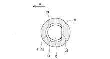
- FIG. 2 is a plan view of the battery module 10 and shows a portion corresponding to one cylindrical battery 11.
- FIG. 3 is a diagram illustrating a state in which the positive electrode current collector plate 30 is removed from FIG. 2 and 3, the exhaust direction in the exhaust duct 15 is indicated by an arrow ⁇ .
- FIG. 4 is a view showing a state in which the safety valve 13 is opened.
- a single safety valve 13 surrounded by an annular fracture portion 14 is formed on the upper end surface (one axial end surface) of the cylindrical battery 11.
- the annular fracture portion 14 is, for example, a sealing plate or a groove formed on the outside of the case body, and is more than the other portion of the battery case 12 when the internal pressure rises due to an abnormality occurring in the cylindrical battery 11. Break preferentially.
- the groove of the rupture portion 14 is generally called an inscription, and is formed by pressing the sealing plate of the battery case 12 or the case body.
- the portion of the sealing plate where the broken portion 14 is formed becomes a thin portion having a thickness smaller than that of the other portion.
- the safety valve 13 may have an elliptical shape or a polygonal shape in plan view, but preferably has a perfect circle shape in plan view.
- the fracture portion 14 is formed in an annular shape having a substantially constant diameter around the center of the upper end surface of the cylindrical battery 11, and the safety valve 13 is provided at the center portion of the upper end surface of the cylindrical battery 11.
- the safety valve 13 is opened outside the cylindrical battery 11, an opening is formed in the sealing plate, and gas is ejected from the opening.
- the exhaust duct 15 is a space in contact with the safety valve 13 through each opening of the first holder 21 and the positive electrode current collector plate 30 and is formed above each cylindrical battery 11.
- the exhaust duct 15 is formed, for example, between the wall of the module case that houses the battery holder 20 and the positive electrode current collector plate 30.
- the exhaust duct 15 may be provided by attaching a cover or the like that forms an exhaust space on the positive electrode current collector plate 30.
- the exhaust duct 15 is provided only at the upper part of the battery module 10. However, when the safety valve 13 is formed on the lower end surface of the cylindrical battery 11, the exhaust duct is provided below each cylindrical battery 11. Is provided.
- the outlet 16 of the exhaust duct 15 opens in one direction of the battery module 10 so that the exhaust direction of the gas ejected from each cylindrical battery 11 is the same direction.
- the outlet 16 of the exhaust duct 15 is formed at one end in the longitudinal direction of the battery holder 20.
- the outlet 16 is an opening formed in one place such as a module case or a cover that constitutes the exhaust duct 15, for example.
- the first holder 21 and the positive electrode current collector plate 30 functioning as the exhaust direction regulating member are provided between the cylindrical batteries 11 and the exhaust duct 15 as described above, and a plurality of openings that expose the safety valves 13. It has parts 24 and 34, respectively. Each of the openings 24 and 34 is formed for each cylindrical battery 11 and overlaps each other in the vertical direction to expose the safety valves 13. Each opening 24, 34 enables each safety valve 13 to be opened, and serves as an exhaust path leading from each safety valve 13 to the exhaust duct 15. Each opening 24 enables connection between the lead portion 33 and the sealing plate.
- the first holder 21 and the positive electrode current collector plate 30 project from the safety valve 13 so as to cover the end of the exhaust duct 15 on the side opposite to the end on the outlet 16 side so as to overlap each safety valve 13. , 35 respectively.
- the flanges 25 and 35 that cover the safety valve 13 of the first holder 21 and the positive electrode current collector plate 30 (portions overhanging on the safety valve 13) allow a part of the safety valve 13 to be connected to the battery when the internal pressure of the cylindrical battery 11 rises.
- the safety valve 13 is pressed from the outside so that it does not open greatly on the flanges 25 and 35 side.
- the portion located on the outlet 16 side of the safety valve 13 is exposed without being covered by the first holder 21 and the positive electrode current collector plate 30.
- the flange portion 25 substantially abuts on the safety valve 13, for example, and restricts displacement due to opening of the safety valve 13.
- the opening 34 and the flange 35 are formed in, for example, two metal plates (base plate 31 and lead plate 32) constituting the positive electrode current collector plate 30.
- the flange portion 25 and the flange portion 35 of the base plate 31 have substantially the same shape and the same dimensions.
- the flange portion 25 and the flange portion 35 of the base plate 31 are overlapped in the vertical direction with their ends aligned.
- the opening 24 and the opening 34 of the base plate 31 also have substantially the same shape and the same dimensions as each other, and overlap each other in the vertical direction with their edges aligned.
- the lead plate 32 only the lead portion 33 may protrude from the safety valve 13, and the portion other than the lead portion 33 may have the same shape as the base plate 31.
- the lead portion 33 extends from the side opposite to the outlet 16 of the exhaust duct 15 to a range overlapping the safety valve 13 in the vertical direction.
- the lead portion 33 extends on the safety valve 13 from the end portion 180 ° opposite to the end portion closest to the outlet 16 with the center of the safety valve 13 as the center with respect to the exhaust direction in the exhaust duct 15, for example.
- the lead portion 33 is formed in a strip shape that is long in the exhaust direction, and is welded to the central portion of the safety valve 13. In this case, the lead portion 33 may contribute to control of the opening direction of the safety valve 13 as a part of the flange portion 35.
- the lead portion 33 When the lead portion 33 extends from the outlet 16 side of the safety valve 13 onto the safety valve 13, or when the lead portion 33 is thin and the safety valve 13 cannot be pressed from the outside when the internal pressure of the battery increases, the lead portion 33 Does not function as an exhaust direction regulating member.
- the collar portion may be formed only on one of the first holder 21 and the positive electrode current collector plate 30, but when the collar portion is formed only on the positive electrode current collector plate 30, the base is thicker than at least the lead plate 32. It is preferable to form a flange on the plate 31.
- the ends of the flange portion 25 and the flange portion 35 of the base plate 31 are linearly formed.
- the flange portion 25 and the flange portion 35 of the base plate 31 are contoured by a circular arc and a straight line connecting both ends thereof, and may be substantially semicircular, for example.
- the opening 24 and the opening 34 of the base plate 31 are also contoured by an arc and a straight line connecting both ends thereof, and may be, for example, substantially semicircular.
- the flange portions 25 and 35 cover 15% to 50% of the entire length of the fracture portion 14.
- the flange portions 25 and 35 are, for example, 20% of the total length of the fracture portion 14 in a half region of the safety valve 13 located on the opposite side to the outlet 16 side of the exhaust duct 15 (hereinafter sometimes referred to as “opposite side region”). It overhangs to cover 50% to 50%.
- the fracture portion 14 is not covered by the flange portions 25 and 35 and is exposed. Preferably it is.
- the flange portions 25 and 35 project on the safety valve 13 so as to cover, for example, 2.5% to 50%, preferably 10% to 25%, of the area of the safety valve 13. As for the opposite region, the flange portions 25 and 35 cover 10% to 100%, preferably 20% to 50%, of the area of the region.
- the positive electrode current collector plate 30 does not cover the outlet side region.
- a part of the lead part 33 may exist on the outlet side region of the safety valve 13. It is preferable that 50% or more of the area of the safety valve 13 is exposed by the openings 24 and 34.
- the safety valve 13 is positioned on the side opposite to the end on the outlet 16 side of the exhaust duct 15 by the flanges 25 and 35 of the first holder 21 and the positive electrode current collector plate 30. The end is pressed from the outside of the cylindrical battery 11. For this reason, the safety valve 13 does not open to the side opposite to the outlet 16 but easily opens to the outlet 16 side. Since the opening direction of the safety valve 13 can be controlled in this way, the gas ejected from the cylindrical battery 11 can be smoothly exhausted from the outlet 16 of the exhaust duct 15. Further, in the control of the valve opening direction, it is not necessary to adjust the direction of each cylindrical battery 11 with respect to the outlet 16 of the exhaust duct 15.
- the lead portion 33 extends from the opposite side of the outlet 16 of the exhaust duct 15 to the range where it overlaps the safety valve 13. Therefore, the lead portion 33 does not prevent the safety valve 13 from being opened, and smoother exhaust is achieved. It becomes possible. Further, since the flange portion 25 of the first holder 21 is substantially in contact with the safety valve 13, the safety valve 13 can be more reliably prevented from opening in the direction opposite to the outlet 16. Moreover, since the edge of the collar parts 25 and 35 is formed in linear form, the safety valve 13 bends along the edge of the collar parts 25 and 35, for example, and a valve opening state is stabilized.
- positive current collectors 30X and 30Y which are modifications of the positive current collector 30, respectively.
- the positive electrode current collector plates 30X and 30Y have openings 34X and 34Y and flange portions 35X and 35Y.
- a resin battery holder or an insulating plate is disposed between the positive electrode current collector plates 30X and 30Y and the cylindrical battery 11, a resin battery holder or an insulating plate is disposed, and the positive electrode current collector plates 30X and 30Y, except for the lead portion 33, are also provided. It is preferable that the same opening part and collar part are formed.
- the lead plate 32 can be the same as that of the positive electrode current collector plate 30, but a lead plate having a shape corresponding to the base plates 31X and 31Y of the positive electrode current collector plates 30X and 30Y may be used.
- the structure of the positive electrode current collecting plates 30, 30X, and 30Y is applied to, for example, the negative electrode current collecting plate when a safety valve is provided on the negative electrode current collecting plate side.
- the opening 34 ⁇ / b> X has an elliptical shape in plan view, and the flange portion 35 ⁇ / b> X has a crescent shape in plan view.
- the ellipse of the opening 34X has a major axis in the direction orthogonal to the exhaust direction in the exhaust duct 15 indicated by the arrow ⁇ .
- the flange portion 35 ⁇ / b> Y has a crescent shape in plan view, but the opening portion 34 ⁇ / b> Y has a perfect circle shape in plan view.
- the center of the opening 34Y is shifted from the center of the safety valve 13 toward the outlet 16, and the circle of the opening 34Y and the circle of the safety valve 13 are not formed concentrically. Also in the embodiment illustrated in FIGS. 5 and 6, the same effect as that of the embodiment illustrated in FIGS. 1 to 4 can be obtained.
Landscapes
- Chemical & Material Sciences (AREA)
- Chemical Kinetics & Catalysis (AREA)
- Electrochemistry (AREA)
- General Chemical & Material Sciences (AREA)
- Engineering & Computer Science (AREA)
- Manufacturing & Machinery (AREA)
- Gas Exhaust Devices For Batteries (AREA)
- Battery Mounting, Suspending (AREA)
- Connection Of Batteries Or Terminals (AREA)
Abstract
実施形態の一例である電池モジュール(10)は、電池内圧が所定値を超えたときに破断する環状の破断部(14)に囲まれた安全弁(13)をそれぞれ有する複数の円筒形電池(11)と、安全弁(13)が開いたときに円筒形電池(11)から噴出するガスをモジュールの外部に導く排気ダクト(15)と、各円筒形電池(11)と排気ダクト(15)との間に設けられる排気方向規定部材とを備える。排気方向規定部材は、各安全弁(13)をそれぞれ露出させる複数の開口部を有し、安全弁(13)のうち排気ダクト(15)の出口側端部と反対側に位置する端部を覆うように各安全弁(13)と重なる範囲にそれぞれ張り出している。
Description
本開示は、電池モジュールに関する。
従来、電池に異常が発生してガスが噴出した際に、そのガスをモジュールの外部に導くための排気ダクトを備えた電池モジュールが知られている。例えば、特許文献1には、内部に安全弁が設けられた電池と、電池から噴出するガスを一方向に誘導するガス整流部を含む接続板と、排気ダクトとを備えた電池モジュールが開示されている。特許文献1には、接続板のガス整流部が、電池からガスが噴出した際に排気ダクト側に折れ曲がり、ガスを一方向に誘導する整流板になると記載されている。
ところで、安全弁は電池ケースの外面に設けられる場合がある。このような電池を搭載する電池モジュールにおいても、安全弁の開弁により電池から噴出するガスが排気ダクトの出口からスムーズに排気されるように、安全弁の開弁方向を制御することは重要な課題である。なお、安全弁を囲う破断部を、例えばC字状に形成して安全弁の開弁方向を制御する方法も考えられるが、この場合は、電池モジュールを製造する際に安全弁の向きが揃うように各電池を配置する必要がある。
本開示の目的は、排気ダクトの出口に対する各電池の向きを調整することなく、排気ダクトの出口の方向に各電池の安全弁を開弁させることが可能な電池モジュールを提供することである。
本開示に係る電池モジュールは、電池内圧が所定値を超えたときに破断する環状の破断部に囲まれた安全弁をそれぞれ有する複数の電池と、前記安全弁が開いたときに前記電池から噴出するガスをモジュールの外部に導く排気ダクトと、前記各電池と前記排気ダクトとの間に設けられる部材であって、前記各安全弁をそれぞれ露出させる複数の開口部を有し、前記安全弁のうち前記排気ダクトの出口側端部と反対側に位置する端部を覆うように前記各安全弁と重なる範囲にそれぞれ張り出した排気方向規定部材とを備えることを特徴とする。
本開示に係る電池モジュールによれば、排気ダクトの出口に対する各電池の向きを調整することなく、排気ダクトの出口の方向に各電池の安全弁を開弁させることができる。本開示に係る電池モジュールによれば、安全弁が開いたときに電池から噴出するガスを排気ダクトの出口からスムーズに排気することが可能である。
本開示の一態様である電池モジュールでは、上述の通り、電池の安全弁のうち排気ダクトの出口側端部と反対側に位置する端部(以下、「反対側端部」という)を覆うように排気方向規定部材が張り出している。本開示の一態様である電池モジュールによれば、排気方向規定部材の安全弁を覆う部分(以下、「鍔部」という)によって、安全弁の上記反対側端部が電池の外側から押えられるため、安全弁は排気ダクトの出口方向に大きく開き易い。このように安全弁の開弁方向を制御できるので、電池から噴出するガスを排気ダクトの出口からスムーズに排気することが可能となる。
本開示の一態様である電池モジュールは、排気方向規定部材として、例えば集電板、絶縁板、及び電池ホルダーから選択される少なくとも1つを備える。これらの部材は、安全弁と干渉しないように設けられることが一般的であるが、本開示の一態様である電池モジュールでは、これらの部材の一部を安全弁の一部と積極的に干渉させることで、安全弁の開弁方向を規定している。特に、集電板のリード部を排気ダクトの出口と反対側から安全弁と重なる範囲に延出させる構成とすれば、リード部によって安全弁の開弁が妨げられず、よりスムーズな排気が可能となる。
以下、本開示の実施形態の一例について詳細に説明する。なお、本開示の電池モジュールは以下で説明する実施形態に限定されない。実施形態の説明で参照する図面は模式的に記載されたものであるから、図面に描画された各構成要素の寸法比率などは以下の説明を参酌して判断されるべきである。本明細書において「略~」とは、略同一を例に説明すると、完全に同一はもとより、実質的に同一と認められるものを含む意図である。
以下では、電池モジュールに搭載される電池として円筒形電池11を例示するが、電池はこれに限定されない。また、説明の便宜上、円筒形電池11の軸方向に沿った方向を電池モジュールの上下方向とし、排気ダクト15側を上とする。
図1は、実施形態の一例である電池モジュール10の断面図である。図1に例示するように、電池モジュール10は、複数の円筒形電池11を備える。円筒形電池11は、電池内圧が所定値を超えたときに破断する環状の破断部14に囲まれた安全弁13を有する。電池モジュール10は、円筒形電池11の安全弁13が開いたときに円筒形電池11から噴出するガスをモジュールの外部に導く排気ダクト15と、各円筒形電池11と排気ダクト15との間に設けられる排気方向規定部材とを備える。詳しくは後述するが、排気方向規定部材は、各円筒形電池11の各安全弁13をそれぞれ露出させる複数の開口部を有し、安全弁13のうち排気ダクト15の出口側端部と反対側に位置する端部を覆うように安全弁13と重なる範囲にそれぞれ張り出している。
電池モジュール10は、複数の円筒形電池11を保持する樹脂製の電池ホルダー20を備える。電池ホルダー20には、各円筒形電池11をそれぞれ収容する収容部23が複数設けられている。電池モジュール10は、1つの電池ホルダー20を含む電池ブロックを1つ又は複数有していてもよい。なお、樹脂製の電池ホルダー20の代わりに、金属製の電池ホルダーを用いてもよい。この場合、各円筒形電池11と後述の集電板との間に絶縁板を設けることが好ましく、当該絶縁板を上記排気方向規定部材としてもよい。
電池モジュール10は、例えば1つの電池ホルダー20に収容される複数の円筒形電池11を並列接続する一対の集電板(正極集電板30及び負極集電板40)を備える。電池モジュール10が電池ホルダー20をそれぞれ含む複数の電池ブロックを有する場合、例えば各電池ブロックが直列接続される。排気ダクト15は、複数の電池ブロックでつながっていてもよいが、好ましくはブロック毎に分離されている。
電池モジュール10は、上から順に、排気ダクト15、正極集電板30、電池ホルダー20に収容された複数の円筒形電池11、及び負極集電板40を備える。本実施形態では、各円筒形電池11の軸方向一端面に安全弁13が設けられており、軸方向一端面が上方を向くように各円筒形電池11が配置されている。電池ホルダー20及び正極集電板30には、各安全弁13を露出させる複数の開口部24,34がそれぞれ形成されており、開口部24,34によって安全弁13から排気ダクト15への排気経路が確保されている。
円筒形電池11は、鉄などの金属製の電池ケース12と、当該ケース内に収容された発電要素とを備える。発電要素には、例えば巻回構造を有する電極体と、非水電解質とが含まれる。円筒形電池11の一例は、リチウムイオン二次電池である。電池ケース12は、発電要素を収容する有底円筒形状のケース本体と、ケース本体の開口部を塞ぐ封口板とで構成される。本実施形態では、封口板が円筒形電池11の正極端子として機能し、封口板に安全弁13が設けられているものとする。ケース本体の側面は絶縁樹脂フィルムで被覆されていてもよく、その場合、ケース本体の下端面が負極端子として機能する。
電池ホルダー20は、各円筒形電池11の上端部を保持する第1ホルダー21と、各円筒形電池11の下端部を保持する第2ホルダー22とを有し、それらを連結して構成されている。収容部23は、第1ホルダー21の凹部23aと、第2ホルダー22の凹部23bとによって形成される。円筒形電池11の上端部は凹部23aに挿入され、円筒形電池11の下端部は凹部23bに挿入される。複数の収容部23は、千鳥状に配置されていてもよく、格子状に配置されていてもよい。詳しくは後述するが、第1ホルダー21は、安全弁13の開弁方向を制御する上記排気方向規定部材として機能する。
第1ホルダー21及び第2ホルダー22は、例えば複数の凹部23a,23bがそれぞれ形成されたトレイ状の部材である。第1ホルダー21は、各円筒形電池11の上端面の周縁部を覆い、各円筒形電池11の上端部を保持している。第1ホルダー21には、複数の開口部24が形成されている。第2ホルダー22は、各円筒形電池11の下端面の周縁部を覆い、各円筒形電池11の下端部を保持している。第2ホルダー22にも、第1ホルダー21と同様に、複数の開口部26が形成されている。
電池ホルダー20は、例えば硬化型樹脂で構成される。具体例としては、不飽和ポリエステル、エポキシ樹脂、メラミン樹脂、フェノール樹脂等の熱硬化性樹脂が挙げられる。硬化型樹脂には、水酸化アルミニウム、炭酸水素ナトリウム等の吸熱フィラー、金属酸化物、金属窒化物等の熱伝導性フィラーなどが含有されていてもよい。なお、樹脂製の電池ホルダー20の代わりに、例えば金属製の電池ホルダーと樹脂製の絶縁板を用いてもよい。この場合、各円筒形電池11の上方に配置される絶縁板には、電池の保持機能を除き、第1ホルダー21と同様の構成を適用できる。
正極集電板30は、各円筒形電池11の各安全弁13にそれぞれ接続された複数のリード部33を有する。上述のように、本実施形態では安全弁13を含む封口板が正極端子として機能するため、安全弁13にリード部33が接続されることで、円筒形電池11の正極と正極集電板30とが電気的に接続される。正極集電板30は、リード部33を除く部分が第1ホルダー21の上に重なり、また開口部34が第1ホルダー21の開口部24と上下方向に重なった状態で配置されている。詳しくは後述するが、正極集電板30は、安全弁13の開弁方向を制御する上記排気方向規定部材として機能する。
正極集電板30は、ベース板31と、複数のリード部33を含むリード板32とで構成されることが好適である。リード板32は、例えばベース板31の下面に接合され、リード部33を除く部分がベース板31と重なっている。ベース板31の厚みは、例えば0.5mm~1.5mmであり、リード板32の厚みは、例えば0.1mm~0.5mmであり、安全弁13の厚みは、例えば0.3mm~1.0mmである。
負極集電板40は、各電池ケース12の下端面にそれぞれ接続された複数のリード部43を有し、円筒形電池11の負極と電気的に接続されている。負極集電板40は、リード部43を除く部分が電池ホルダー20の第2ホルダー22の下に重なり、また開口部36が第2ホルダー22の開口部26と上下方向に重なった状態で配置されている。負極集電板40は、正極集電板30と同様に、ベース板41と、複数のリード部43を含むリード板42とで構成されることが好適である。
以下、図2~図4を適宜参照しながら、円筒形電池11の安全弁13、及び排気方向規定部材として機能する第1ホルダー21、正極集電板30について更に詳説する。図2は、電池モジュール10の平面図であって、1つの円筒形電池11に対応する部分を示す図である。図3は、図2において正極集電板30を取り外した状態を示す図である。図2及び図3では、排気ダクト15における排気方向を矢印αで示す。図4は、安全弁13が開いた状態を示す図である。
図1~図3に例示するように、円筒形電池11の上端面(軸方向一端面)には、環状の破断部14に囲まれた1つの安全弁13が形成されている。環状の破断部14は、例えば封口板、或いはケース本体の外側に形成された溝であって、円筒形電池11に異常が発生して内圧が上昇したときに電池ケース12の他の部分よりも優先的に破断する。破断部14の溝は、一般的に刻印と呼ばれ、電池ケース12の封口板、或いはケース本体のプレス加工により形成される。封口板の破断部14が形成された部分は、他の部分よりも厚みが薄い薄肉部となる。
安全弁13は、平面視楕円形状又は多角形状とすることもできるが、好ましくは平面視真円形状を有する。本実施形態では、破断部14が円筒形電池11の上端面の真中を中心として直径が略一定の環状に形成され、安全弁13が円筒形電池11の上端面の中央部に設けられている。円筒形電池11では、内圧が所定値を超えて破断部14が破断することにより、安全弁13が円筒形電池11の外側に開いて封口板に開口が形成され、当該開口からガスが噴出する。
排気ダクト15は、第1ホルダー21及び正極集電板30の各開口部を介して安全弁13と接する空間であって、各円筒形電池11の上方に形成されている。排気ダクト15は、例えば電池ホルダー20を収容するモジュールケースの壁部と正極集電板30との間に形成される。或いは、正極集電板30の上に排気空間を形成するカバー等を取り付けて排気ダクト15を設けてもよい。図1に示す例では、電池モジュール10の上部のみに排気ダクト15が設けられているが、円筒形電池11の下端面に安全弁13が形成される場合は各円筒形電池11の下方に排気ダクトが設けられる。
排気ダクト15の出口16は、各円筒形電池11から噴出されるガスの排気方向が同じ方向となるように、電池モジュール10の一方向に開口している。電池ホルダー20が平面視略矩形状を呈する場合、例えば電池ホルダー20の長手方向一端部に排気ダクト15の出口16が形成される。出口16は、例えば排気ダクト15を構成するモジュールケース、カバー等の1箇所に形成される開口部である。
上記排気方向規定部材として機能する第1ホルダー21及び正極集電板30は、上述のように、各円筒形電池11と排気ダクト15との間に設けられ、各安全弁13を露出させる複数の開口部24,34をそれぞれ有する。各開口部24,34は、1つの円筒形電池11につき1つずつ形成され、互いに上下方向に重なって各安全弁13を露出させる。各開口部24,34は、各安全弁13の開弁を可能とし、各安全弁13から排気ダクト15につながる排気経路となる。また、各開口部24はリード部33と封口板との接続を可能とする。
第1ホルダー21及び正極集電板30は、安全弁13のうち排気ダクト15の出口16側端部と反対側に位置する端部を覆うように各安全弁13と重なる範囲にそれぞれ張り出した鍔部25,35をそれぞれ有する。第1ホルダー21及び正極集電板30の安全弁13を覆う部分(安全弁13上に張り出した部分)である鍔部25,35は、円筒形電池11の内圧上昇時に安全弁13の一部を電池の外側から押えて、安全弁13が鍔部25,35側で大きく開かないようにする。他方、安全弁13の出口16側に位置する部分は、第1ホルダー21及び正極集電板30に覆われず露出している。鍔部25は、例えば安全弁13に略当接して、安全弁13の開弁による変位を規制している。
開口部34及び鍔部35は、例えば正極集電板30を構成する2枚の金属板(ベース板31及びリード板32)に形成される。本実施形態では、鍔部25及びベース板31の鍔部35が互いに略同一形状、同一寸法を有する。鍔部25及びベース板31の鍔部35は、各々の端が一致した状態で上下方向に重なっている。開口部24及びベース板31の開口部34も、互いに略同一形状、同一寸法を有し、各々の縁が一致した状態で上下方向に重なっている。リード板32は、リード部33のみが安全弁13上に張り出していてもよく、リード部33以外の部分がベース板31と同様の形状を有していてもよい。
リード部33は、排気ダクト15の出口16と反対側から安全弁13と上下方向に重なる範囲に延出する。リード部33は、例えば排気ダクト15における排気方向に対して、安全弁13の真ん中を中心として出口16に最も近い端部と180°反対側に位置する端部側から安全弁13上に延出する。リード部33は、排気方向に長い帯状に形成され、安全弁13の中央部に溶接されている。この場合、リード部33は鍔部35の一部として安全弁13の開弁方向の制御に寄与してもよい。
なお、リード部33が安全弁13の出口16側から安全弁13上に延出する場合、或いはリード部33の厚みが薄く電池の内圧上昇時に安全弁13を外側から押えることができない場合は、リード部33は排気方向規定部材として機能しない。鍔部は、第1ホルダー21及び正極集電板30の一方のみに形成されてもよいが、正極集電板30のみに鍔部が形成される場合は、少なくともリード板32より厚みのあるベース板31に鍔部を形成することが好ましい。
図2及び図3に示す例では、鍔部25及びベース板31の鍔部35の端が直線状に形成されている。鍔部25及びベース板31の鍔部35は、円弧とその両端をつなぐ直線とで輪郭が形成され、例えば略半円形状であってもよい。開口部24及びベース板31の開口部34も、円弧とその両端をつなぐ直線とで輪郭が形成され、例えば略半円形状であってもよい。
鍔部25,35は、破断部14の全長の15%~50%を覆っていることが好ましい。鍔部25,35は、例えば安全弁13のうち排気ダクト15の出口16側と反対側に位置する半分の領域(以下、「反対側領域」という場合がある)において、破断部14の全長の20%~50%を覆うように張り出している。他方、安全弁13のうち排気ダクト15の出口16側に位置する半分の領域(以下、「出口側領域」という場合がある)において、破断部14は鍔部25,35に覆われず露出していることが好ましい。このように鍔部25,35を設けることで、安全弁13の開弁を阻害することなく安全弁13の変位を規制し、開弁方向を制御することが容易になる。
鍔部25,35は、例えば安全弁13の面積の2.5%~50%、好ましくは10%~25%を覆うように安全弁13上に張り出している。反対側領域について言えば、当該領域の面積の10%~100%、好ましくは20%~50%を鍔部25,35が覆っている。安全弁13の開弁を阻害しないように、正極集電板30は出口側領域を覆わないことが好ましい。リード部33の一部については、安全弁13の出口側領域上に存在してもよい。安全弁13は、その面積の50%以上が開口部24,34によって露出していることが好ましい。
図4に例示するように、円筒形電池11の内圧が上昇して所定値を超えると、破断部14で封口板が破断し、安全弁13が外側に開く。これにより、封口板に開口が形成され、円筒形電池11からガスが噴出する。噴出したガスは、開口部24,34を通って排気ダクト15に流入し、出口16から電池モジュール10の外部に排気される。
上記構成を備えた電池モジュール10によれば、第1ホルダー21及び正極集電板30の鍔部25,35によって、安全弁13のうち排気ダクト15の出口16側の端部と反対側に位置する端部が円筒形電池11の外側から押えられる。このため、安全弁13は出口16と反対側に開かず、出口16側に大きく開き易い。このように安全弁13の開弁方向を制御できるので、円筒形電池11から噴出するガスを排気ダクト15の出口16からスムーズに排気することが可能となる。また、かかる開弁方向の制御において、排気ダクト15の出口16に対する各円筒形電池11の向きを調整することは不要である。
電池モジュール10では、リード部33が排気ダクト15の出口16と反対側から安全弁13と重なる範囲に延出しているので、リード部33によって安全弁13の開弁が妨げられず、よりスムーズな排気が可能となる。また、第1ホルダー21の鍔部25は安全弁13に略当接しているため、安全弁13が出口16と反対方向に開弁することをより確実に防止できる。また、鍔部25,35の端が直線状に形成されているため、例えば安全弁13は鍔部25,35の端に沿って折れ曲がり、開弁状態が安定化する。
図5及び図6は、正極集電板30の変形例である正極集電板30X,30Yをそれぞれ示す。正極集電板30X,30Yは、正極集電板30と同様に、開口部34X,34Yと、鍔部35X,35Yとを有する。正極集電板30X,30Yと円筒形電池11との間には、樹脂製の電池ホルダー又は絶縁板が配置されるが、それらにも、リード部33を除き、正極集電板30X,30Yと同様の開口部と鍔部が形成されていることが好ましい。リード板32には、正極集電板30の場合と同じものを適用できるが、正極集電板30X,30Yのベース板31X,31Yに対応する形状のリード板を用いてもよい。なお、正極集電板30,30X,30Yの構成は、負極集電板側に安全弁が設けられる場合は、例えば負極集電板に適用される。
図5に示す例では、開口部34Xが平面視楕円形状を有し、鍔部35Xが平面視三日月形状を有する。開口部34Xの楕円は、矢印αで示す排気ダクト15における排気方向と直交する方向が長軸となる。図6に示す例では、正極集電板30Xの場合と同様に、鍔部35Yは平面視三日月形状を有するが、開口部34Yは平面視真円形状を有する。開口部34Yの中心は、安全弁13の中心から出口16側にずれており、開口部34Yの円と安全弁13の円は同心円状に形成されていない。図5及び図6に例示する形態においても、図1~図4に例示する形態と同様の効果が得られる。
10 電池モジュール、11 円筒形電池、12 電池ケース、13 安全弁、14 破断部、15 排気ダクト、16 出口、20 電池ホルダー、21 第1ホルダー、22 第2ホルダー、23 収容部、23a,23b 凹部、24,26 開口部、25 鍔部、30 正極集電板、31 ベース板、32 リード板、33 リード部、34,36 開口部、35 鍔部、40 負極集電板、41 ベース板、42 リード板、43 リード部
Claims (7)
- 電池内圧が所定値を超えたときに破断する環状の破断部に囲まれた安全弁をそれぞれ有する複数の電池と、
前記安全弁が開いたときに前記電池から噴出するガスをモジュールの外部に導く排気ダクトと、
前記各電池と前記排気ダクトとの間に設けられる部材であって、前記各安全弁をそれぞれ露出させる複数の開口部を有し、前記安全弁のうち前記排気ダクトの出口側端部と反対側に位置する端部を覆うように前記各安全弁と重なる範囲にそれぞれ張り出した排気方向規定部材と、
を備える、電池モジュール。 - 前記排気方向規定部材として、前記各安全弁にそれぞれ接続された複数のリード部を有する集電板を備え、
前記各リード部は、前記排気ダクトの出口と反対側から前記各安全弁と重なる範囲に延出している、請求項1に記載の電池モジュール。 - 前記各安全弁にそれぞれ接続された複数のリード部を有する集電板と、
前記各電池と前記集電板との間に設けられた絶縁板と、
を備え、
前記集電板及び前記絶縁板の少なくとも一方が前記排気方向規定部材となる、請求項1又は2に記載の電池モジュール。 - 前記排気方向規定部材として、前記各電池を保持する樹脂製のホルダーを備える、請求項1又は2に記載の電池モジュール。
- 前記排気方向規定部材の前記安全弁を覆う部分は、前記破断部の全長の15%~50%を覆っている、請求項1~4のいずれか1項に記載の電池モジュール。
- 前記排気方向規定部材は、前記安全弁に当接し、前記安全弁の開弁による変位を規制する、請求項1~5のいずれか1項に記載の電池モジュール。
- 前記排気方向規定部材の前記安全弁を覆う部分の端は、直線状に形成されている、請求項1~6のいずれか1項に記載の電池モジュール。
Priority Applications (3)
| Application Number | Priority Date | Filing Date | Title |
|---|---|---|---|
| US16/470,256 US11322793B2 (en) | 2016-12-27 | 2017-12-13 | Battery module |
| JP2018559009A JP6920661B2 (ja) | 2016-12-27 | 2017-12-13 | 電池モジュール |
| CN201780079162.0A CN110088937B (zh) | 2016-12-27 | 2017-12-13 | 电池模块 |
Applications Claiming Priority (2)
| Application Number | Priority Date | Filing Date | Title |
|---|---|---|---|
| JP2016-252405 | 2016-12-27 | ||
| JP2016252405 | 2016-12-27 |
Publications (1)
| Publication Number | Publication Date |
|---|---|
| WO2018123574A1 true WO2018123574A1 (ja) | 2018-07-05 |
Family
ID=62707349
Family Applications (1)
| Application Number | Title | Priority Date | Filing Date |
|---|---|---|---|
| PCT/JP2017/044638 WO2018123574A1 (ja) | 2016-12-27 | 2017-12-13 | 電池モジュール |
Country Status (4)
| Country | Link |
|---|---|
| US (1) | US11322793B2 (ja) |
| JP (1) | JP6920661B2 (ja) |
| CN (1) | CN110088937B (ja) |
| WO (1) | WO2018123574A1 (ja) |
Cited By (4)
| Publication number | Priority date | Publication date | Assignee | Title |
|---|---|---|---|---|
| WO2020134054A1 (zh) * | 2018-12-29 | 2020-07-02 | 比亚迪股份有限公司 | 动力电池包及车辆 |
| WO2021132222A1 (ja) * | 2019-12-27 | 2021-07-01 | パナソニックIpマネジメント株式会社 | 蓄電モジュール |
| DE102020202306A1 (de) | 2020-02-24 | 2021-08-26 | Volkswagen Aktiengesellschaft | Batteriemodul für ein Hochvolt-Batteriesystem |
| US11955651B2 (en) | 2019-01-09 | 2024-04-09 | Byd Company Limited | Power battery pack and electric vehicle |
Families Citing this family (4)
| Publication number | Priority date | Publication date | Assignee | Title |
|---|---|---|---|---|
| DE102018202120A1 (de) * | 2018-02-12 | 2019-08-14 | Airbus Defence and Space GmbH | Batterieanordnung zur strukturellen Integration von Batterien in ein Fahrzeug |
| DE102018204420A1 (de) | 2018-03-22 | 2019-09-26 | Airbus Defence and Space GmbH | Batterieanordnung zur lasttragenden strukturellen Integration von Batterien in ein Fahrzeug |
| CN113594598B (zh) * | 2021-07-29 | 2023-05-12 | 中国第一汽车股份有限公司 | 一种电池模组及电池包 |
| KR20230160176A (ko) * | 2022-05-16 | 2023-11-23 | 주식회사 엘지에너지솔루션 | 배터리 팩 및 이를 포함하는 자동차 |
Citations (5)
| Publication number | Priority date | Publication date | Assignee | Title |
|---|---|---|---|---|
| WO2012017586A1 (ja) * | 2010-08-06 | 2012-02-09 | パナソニック株式会社 | 電池モジュール |
| WO2014125806A1 (ja) * | 2013-02-14 | 2014-08-21 | 三洋電機株式会社 | 電池ブロック |
| JP2015018706A (ja) * | 2013-07-11 | 2015-01-29 | 株式会社豊田自動織機 | 蓄電装置モジュール |
| WO2017150051A1 (ja) * | 2016-03-01 | 2017-09-08 | 日立オートモティブシステムズ株式会社 | 二次電池モジュール |
| WO2018003291A1 (ja) * | 2016-06-30 | 2018-01-04 | 三洋電機株式会社 | 電池ブロック |
Family Cites Families (6)
| Publication number | Priority date | Publication date | Assignee | Title |
|---|---|---|---|---|
| MY124164A (en) * | 1997-05-09 | 2006-06-30 | Fukuda Metal Foil Powder | Closed battery and closing member |
| CN102484235A (zh) * | 2010-07-30 | 2012-05-30 | 松下电器产业株式会社 | 电池模块 |
| JP2013037873A (ja) | 2011-08-08 | 2013-02-21 | Panasonic Corp | 電池モジュール |
| US11233292B2 (en) | 2014-03-28 | 2022-01-25 | Sanyo Electric Co., Ltd. | Cylindrical sealed battery and battery pack |
| US20200313129A1 (en) * | 2016-06-30 | 2020-10-01 | Sanyo Electric Co., Ltd. | Battery block |
| WO2018100983A1 (ja) * | 2016-11-30 | 2018-06-07 | パナソニックIpマネジメント株式会社 | 電池モジュール |
-
2017
- 2017-12-13 CN CN201780079162.0A patent/CN110088937B/zh active Active
- 2017-12-13 JP JP2018559009A patent/JP6920661B2/ja active Active
- 2017-12-13 US US16/470,256 patent/US11322793B2/en active Active
- 2017-12-13 WO PCT/JP2017/044638 patent/WO2018123574A1/ja active Application Filing
Patent Citations (5)
| Publication number | Priority date | Publication date | Assignee | Title |
|---|---|---|---|---|
| WO2012017586A1 (ja) * | 2010-08-06 | 2012-02-09 | パナソニック株式会社 | 電池モジュール |
| WO2014125806A1 (ja) * | 2013-02-14 | 2014-08-21 | 三洋電機株式会社 | 電池ブロック |
| JP2015018706A (ja) * | 2013-07-11 | 2015-01-29 | 株式会社豊田自動織機 | 蓄電装置モジュール |
| WO2017150051A1 (ja) * | 2016-03-01 | 2017-09-08 | 日立オートモティブシステムズ株式会社 | 二次電池モジュール |
| WO2018003291A1 (ja) * | 2016-06-30 | 2018-01-04 | 三洋電機株式会社 | 電池ブロック |
Cited By (4)
| Publication number | Priority date | Publication date | Assignee | Title |
|---|---|---|---|---|
| WO2020134054A1 (zh) * | 2018-12-29 | 2020-07-02 | 比亚迪股份有限公司 | 动力电池包及车辆 |
| US11955651B2 (en) | 2019-01-09 | 2024-04-09 | Byd Company Limited | Power battery pack and electric vehicle |
| WO2021132222A1 (ja) * | 2019-12-27 | 2021-07-01 | パナソニックIpマネジメント株式会社 | 蓄電モジュール |
| DE102020202306A1 (de) | 2020-02-24 | 2021-08-26 | Volkswagen Aktiengesellschaft | Batteriemodul für ein Hochvolt-Batteriesystem |
Also Published As
| Publication number | Publication date |
|---|---|
| US20200099030A1 (en) | 2020-03-26 |
| JP6920661B2 (ja) | 2021-08-18 |
| JPWO2018123574A1 (ja) | 2019-10-31 |
| CN110088937A (zh) | 2019-08-02 |
| CN110088937B (zh) | 2022-04-08 |
| US11322793B2 (en) | 2022-05-03 |
Similar Documents
| Publication | Publication Date | Title |
|---|---|---|
| WO2018123574A1 (ja) | 電池モジュール | |
| CN109643776B (zh) | 电池模块 | |
| US11916249B2 (en) | Cover assembly of secondary battery and secondary battery | |
| US20210126316A1 (en) | Battery block | |
| WO2006114940A1 (ja) | 二次電池 | |
| WO2016104734A1 (ja) | 蓄電素子 | |
| US10644272B2 (en) | Cap assembly and secondary battery | |
| WO2013122005A1 (ja) | 電池用防火装置 | |
| US10333120B2 (en) | Cylindrical secondary battery with reduced circumferential surface rupture | |
| JP2023134644A (ja) | 電池 | |
| JP2017195056A (ja) | コネクタ構造、バスバー部材及び電池モジュール | |
| EP3614451B1 (en) | Secondary battery | |
| KR20100059964A (ko) | 밀폐형 전지 | |
| US8592077B2 (en) | Rechargeable battery | |
| JP6111856B2 (ja) | 蓄電装置 | |
| JPWO2012115131A1 (ja) | 二次電池及びリチウムイオン電池 | |
| KR20220119409A (ko) | 전지 셀, 전지, 전기 장치, 전지 셀의 제조 방법 및 시스템 | |
| JP2007265656A (ja) | 角形電池ケース及び角形電池 | |
| US20220320572A1 (en) | Secondary battery | |
| US20220384915A1 (en) | Non-aqueous electrolyte secondary battery | |
| JP2008270032A (ja) | 二次電池モジュール | |
| JP2023531204A (ja) | 二次電池 | |
| EP3800697A1 (en) | Secondary battery | |
| KR20130024576A (ko) | 이차전지용 캡 어셈블리 및 이를 채용한 이차전지 | |
| US10141599B2 (en) | Non-aqueous electrolyte secondary battery |
Legal Events
| Date | Code | Title | Description |
|---|---|---|---|
| 121 | Ep: the epo has been informed by wipo that ep was designated in this application |
Ref document number: 17885556 Country of ref document: EP Kind code of ref document: A1 |
|
| ENP | Entry into the national phase |
Ref document number: 2018559009 Country of ref document: JP Kind code of ref document: A |
|
| NENP | Non-entry into the national phase |
Ref country code: DE |
|
| 122 | Ep: pct application non-entry in european phase |
Ref document number: 17885556 Country of ref document: EP Kind code of ref document: A1 |