WO2018123444A1 - Dispositif de traitement d'image et procédé de traitement d'image - Google Patents
Dispositif de traitement d'image et procédé de traitement d'image Download PDFInfo
- Publication number
- WO2018123444A1 WO2018123444A1 PCT/JP2017/043355 JP2017043355W WO2018123444A1 WO 2018123444 A1 WO2018123444 A1 WO 2018123444A1 JP 2017043355 W JP2017043355 W JP 2017043355W WO 2018123444 A1 WO2018123444 A1 WO 2018123444A1
- Authority
- WO
- WIPO (PCT)
- Prior art keywords
- unit
- image
- image processing
- boundary
- newly introduced
- Prior art date
Links
Images


Classifications
-
- H—ELECTRICITY
- H04—ELECTRIC COMMUNICATION TECHNIQUE
- H04N—PICTORIAL COMMUNICATION, e.g. TELEVISION
- H04N19/00—Methods or arrangements for coding, decoding, compressing or decompressing digital video signals
- H04N19/10—Methods or arrangements for coding, decoding, compressing or decompressing digital video signals using adaptive coding
- H04N19/102—Methods or arrangements for coding, decoding, compressing or decompressing digital video signals using adaptive coding characterised by the element, parameter or selection affected or controlled by the adaptive coding
- H04N19/117—Filters, e.g. for pre-processing or post-processing
-
- H—ELECTRICITY
- H04—ELECTRIC COMMUNICATION TECHNIQUE
- H04N—PICTORIAL COMMUNICATION, e.g. TELEVISION
- H04N19/00—Methods or arrangements for coding, decoding, compressing or decompressing digital video signals
- H04N19/10—Methods or arrangements for coding, decoding, compressing or decompressing digital video signals using adaptive coding
- H04N19/134—Methods or arrangements for coding, decoding, compressing or decompressing digital video signals using adaptive coding characterised by the element, parameter or criterion affecting or controlling the adaptive coding
- H04N19/157—Assigned coding mode, i.e. the coding mode being predefined or preselected to be further used for selection of another element or parameter
-
- H—ELECTRICITY
- H04—ELECTRIC COMMUNICATION TECHNIQUE
- H04N—PICTORIAL COMMUNICATION, e.g. TELEVISION
- H04N19/00—Methods or arrangements for coding, decoding, compressing or decompressing digital video signals
- H04N19/10—Methods or arrangements for coding, decoding, compressing or decompressing digital video signals using adaptive coding
- H04N19/169—Methods or arrangements for coding, decoding, compressing or decompressing digital video signals using adaptive coding characterised by the coding unit, i.e. the structural portion or semantic portion of the video signal being the object or the subject of the adaptive coding
- H04N19/17—Methods or arrangements for coding, decoding, compressing or decompressing digital video signals using adaptive coding characterised by the coding unit, i.e. the structural portion or semantic portion of the video signal being the object or the subject of the adaptive coding the unit being an image region, e.g. an object
- H04N19/176—Methods or arrangements for coding, decoding, compressing or decompressing digital video signals using adaptive coding characterised by the coding unit, i.e. the structural portion or semantic portion of the video signal being the object or the subject of the adaptive coding the unit being an image region, e.g. an object the region being a block, e.g. a macroblock
-
- H—ELECTRICITY
- H04—ELECTRIC COMMUNICATION TECHNIQUE
- H04N—PICTORIAL COMMUNICATION, e.g. TELEVISION
- H04N19/00—Methods or arrangements for coding, decoding, compressing or decompressing digital video signals
- H04N19/10—Methods or arrangements for coding, decoding, compressing or decompressing digital video signals using adaptive coding
- H04N19/169—Methods or arrangements for coding, decoding, compressing or decompressing digital video signals using adaptive coding characterised by the coding unit, i.e. the structural portion or semantic portion of the video signal being the object or the subject of the adaptive coding
- H04N19/182—Methods or arrangements for coding, decoding, compressing or decompressing digital video signals using adaptive coding characterised by the coding unit, i.e. the structural portion or semantic portion of the video signal being the object or the subject of the adaptive coding the unit being a pixel
-
- H—ELECTRICITY
- H04—ELECTRIC COMMUNICATION TECHNIQUE
- H04N—PICTORIAL COMMUNICATION, e.g. TELEVISION
- H04N19/00—Methods or arrangements for coding, decoding, compressing or decompressing digital video signals
- H04N19/10—Methods or arrangements for coding, decoding, compressing or decompressing digital video signals using adaptive coding
- H04N19/169—Methods or arrangements for coding, decoding, compressing or decompressing digital video signals using adaptive coding characterised by the coding unit, i.e. the structural portion or semantic portion of the video signal being the object or the subject of the adaptive coding
- H04N19/186—Methods or arrangements for coding, decoding, compressing or decompressing digital video signals using adaptive coding characterised by the coding unit, i.e. the structural portion or semantic portion of the video signal being the object or the subject of the adaptive coding the unit being a colour or a chrominance component
-
- H—ELECTRICITY
- H04—ELECTRIC COMMUNICATION TECHNIQUE
- H04N—PICTORIAL COMMUNICATION, e.g. TELEVISION
- H04N19/00—Methods or arrangements for coding, decoding, compressing or decompressing digital video signals
- H04N19/80—Details of filtering operations specially adapted for video compression, e.g. for pixel interpolation
- H04N19/82—Details of filtering operations specially adapted for video compression, e.g. for pixel interpolation involving filtering within a prediction loop
-
- H—ELECTRICITY
- H04—ELECTRIC COMMUNICATION TECHNIQUE
- H04N—PICTORIAL COMMUNICATION, e.g. TELEVISION
- H04N19/00—Methods or arrangements for coding, decoding, compressing or decompressing digital video signals
- H04N19/85—Methods or arrangements for coding, decoding, compressing or decompressing digital video signals using pre-processing or post-processing specially adapted for video compression
- H04N19/86—Methods or arrangements for coding, decoding, compressing or decompressing digital video signals using pre-processing or post-processing specially adapted for video compression involving reduction of coding artifacts, e.g. of blockiness
Definitions
- the present disclosure relates to an image processing apparatus and an image processing method.
- a deblocking filter is applied to block boundaries to suppress image quality degradation caused by block distortion that occurs during image coding. (See Non-Patent Document 1).
- determination of whether or not to apply a deblocking filter and selection of filter strength are performed based on the boundary strength value bS of the block boundary.
- Non-Patent Document 2 introduces a new encoding process that was not introduced in HEVC / H.265.
- Non-Patent Document 2 describes conversion processing that is more complicated than HEVC / H.265, an increase in new modes in the prediction mode, and the like.
- This disclosure has been made in view of such a situation, and is intended to further reduce block distortion.
- a decoding unit that decodes an encoded stream to generate a decoded image, and a newly introduced encoding process or a new one for a block boundary of the decoded image generated by the decoding unit
- an image processing apparatus comprising: a filtering unit that applies a deblocking filter to pixels located in the vicinity of the block boundary according to a boundary strength value set based on information relating to the introduced main encoding process .
- decoding the encoded stream to generate a decoded image Targeting the block boundary of the decoded image, the block is located in the vicinity of the block boundary according to the boundary strength value set based on the information related to the newly introduced encoding process or the newly introduced main encoding process Applying a deblocking filter to the pixel is provided.
- a filtering unit that applies a deblocking filter to pixels located in the vicinity of the block boundary, and an encoding unit that encodes an image using the decoded image to which the deblocking filter has been applied by the filtering unit;
- An image processing apparatus is provided.
- the boundary strength set based on the information related to the newly introduced encoding process or the newly introduced main encoding process for the block boundary of the locally decoded decoded image An image processing method comprising: applying a deblocking filter to pixels located near the block boundary according to a value; and encoding an image using the decoded image to which the deblocking filter is applied Is provided.
- block distortion can be further reduced.
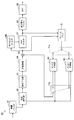
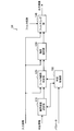
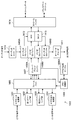
- FIG. 1 is a block diagram illustrating an example of a configuration of an image encoding device 10 that is an aspect of an image processing device according to an embodiment of the present disclosure. It is a block diagram which shows an example of a structure of the image decoding apparatus 60 which is an aspect of the image processing apparatus which concerns on the embodiment. It is explanatory drawing for demonstrating the outline
- FIG. 3 is a block diagram showing an example of a detailed configuration of a deblocking filter according to the same embodiment It is a flowchart which shows an example of the flow of the process by the deblocking filter concerning the embodiment.
- FIG. 20 is a block diagram illustrating a main configuration example of a computer. It is a block diagram which shows an example of a schematic structure of a television apparatus. It is a block diagram which shows an example of a schematic structure of a mobile telephone. It is a block diagram which shows an example of a schematic structure of a recording / reproducing apparatus. It is a block diagram which shows an example of a schematic structure of an imaging device. It is a block diagram which shows an example of a schematic structure of a video set. It is a block diagram which shows an example of a schematic structure of a video processor. It is a block diagram which shows the other example of the schematic structure of a video processor. It is a block diagram which shows an example of a schematic structure of a network system.
- a plurality of constituent elements having substantially the same functional configuration may be distinguished by adding different alphabets after the same reference numeral.
- it is not necessary to particularly distinguish each of a plurality of constituent elements having substantially the same functional configuration only the same reference numerals are given.
- FIG. 1 is a block diagram illustrating an example of a configuration of an image encoding device 10 that is an aspect of an image processing device according to an embodiment of the present disclosure.
- the image encoding device 10 includes a rearrangement buffer 11, a control unit 12, a subtraction unit 13, a conversion unit 14, a quantization unit 15, a lossless encoding unit 16, an accumulation buffer 17, and an inverse quantization unit 21.
- the rearrangement buffer 11 rearranges the image data of a series of images constituting the video to be encoded in accordance with a GOP (Group of Pictures) structure related to the encoding process.
- the rearrangement buffer 11 outputs the rearranged image data to the control unit 12, the subtraction unit 13, the intra prediction unit 30, and the inter prediction unit 40.
- the control unit 12 divides the image data into processing unit blocks based on the block size of the processing unit designated externally or in advance. An example of block division will be described later. Moreover, the control part 12 determines the encoding parameter which concerns on an encoding process based on RDO (Rate-Distortion Optimization), for example. The determined encoding parameter is supplied to each unit.
- RDO Rate-Distortion Optimization
- the subtraction unit 13 calculates prediction error data that is a difference between the image data input from the rearrangement buffer 11 and the predicted image data, and outputs the calculated prediction error data to the conversion unit 14.
- the conversion unit 14 performs conversion processing for each of one or more conversion blocks set in each area.
- a transformation matrix related to transformation applied by the transformation unit 14 may be selected based on, for example, an encoding parameter supplied from the control unit 12.
- the conversion unit 14 outputs the conversion coefficient data obtained by converting the prediction error data input from the subtraction unit 13 for each conversion block to the quantization unit 15.
- the quantization unit 15 is supplied with transform coefficient data input from the transform unit 14 and a rate control signal from a rate control unit 18 described later.
- the quantizing unit 15 quantizes the transform coefficient data and outputs the quantized transform coefficient data (hereinafter also referred to as quantized data) to the lossless encoding unit 16 and the inverse quantization unit 21. Further, the quantization unit 15 changes the bit rate of the quantized data input to the lossless encoding unit 16 by switching the quantization scale based on the rate control signal from the rate control unit 18.
- the lossless encoding unit 16 generates an encoded stream by encoding the quantized data input from the quantizing unit 15. In addition, the lossless encoding unit 16 encodes various encoding parameters referred to by the decoder, and inserts the encoded encoding parameters into the encoded stream.
- the encoding parameter encoded by the lossless encoding unit 16 may include the encoding parameter determined by the control unit 12 described above.
- the lossless encoding unit 16 outputs the generated encoded stream to the accumulation buffer 17.
- the accumulation buffer 17 temporarily accumulates the encoded stream input from the lossless encoding unit 16 using a storage medium such as a semiconductor memory. Then, the accumulation buffer 17 outputs the accumulated encoded stream to a transmission unit (not shown) (for example, a communication interface or a connection interface with a peripheral device) at a rate corresponding to the bandwidth of the transmission path.
- a transmission unit for example, a communication interface or a connection interface with a peripheral device
- the rate control unit 18 monitors the free capacity of the accumulation buffer 17. Then, the rate control unit 18 generates a rate control signal according to the free capacity of the accumulation buffer 17 and outputs the generated rate control signal to the quantization unit 15. For example, the rate control unit 18 generates a rate control signal for reducing the bit rate of the quantized data when the free capacity of the storage buffer 17 is small. For example, when the free capacity of the accumulation buffer 17 is sufficiently large, the rate control unit 18 generates a rate control signal for increasing the bit rate of the quantized data.
- the inverse quantization unit 21, the inverse transformation unit 22, and the addition unit 23 constitute a local decoder.
- the local decoder has a role of locally decoding the decoded image data from the encoded data.
- the inverse quantization unit 21 inversely quantizes the quantized data with the same quantization parameter used by the quantizing unit 15 and restores transform coefficient data. Then, the inverse quantization unit 21 outputs the restored transform coefficient data to the inverse transform unit 22.
- the inverse transform unit 22 restores the prediction error data by executing an inverse transform process on the transform coefficient data input from the inverse quantization unit 21. Then, the inverse transformation unit 22 outputs the restored prediction error data to the addition unit 23.
- the adding unit 23 adds the decoded prediction error data input from the inverse conversion unit 22 and the predicted image data input from the intra prediction unit 30 or the inter prediction unit 40, thereby obtaining decoded image data (reconstructed image). ) Is generated. Then, the adder 23 outputs the generated decoded image data to the deblock filter 24 a and the frame memory 26.
- the deblock filter 24a and the SAO filter 25 are in-loop filters for the purpose of improving the image quality of the reconstructed image or improving the encoding efficiency, respectively.
- the deblocking filter 24 a reduces the block distortion by filtering the decoded image data input from the adding unit 23, and outputs the decoded image data after filtering to the SAO filter 25.
- the processing by the deblocking filter 24a will be described in detail later.
- the SAO filter 25 removes noise by applying edge offset processing or band offset processing to the decoded image data input from the deblocking filter 24a, and outputs the processed decoded image data to the frame memory 26.
- the frame memory 26 stores the decoded image data before filtering input from the adder 23 and the decoded image data after application of the in-loop filter input from the SAO filter 25 using a storage medium.
- the switch 27 reads decoded image data before filtering used for intra prediction from the frame memory 26, and supplies the read decoded image data to the intra prediction unit 30 as reference image data. Further, the switch 27 reads out the decoded image data after filtering used for inter prediction from the frame memory 26 and supplies the read out decoded image data to the inter prediction unit 40 as reference image data.
- the mode setting unit 28 sets the prediction encoding mode for each block based on the comparison of the costs input from the intra prediction unit 30 and the inter prediction unit 40. For the block for which the intra prediction mode is set, the mode setting unit 28 outputs the prediction image data generated by the intra prediction unit 30 to the subtraction unit 13 and the addition unit 23, and at the same time, information about the intra prediction is obtained from the lossless encoding unit 16. Output to. The mode setting unit 28 outputs the prediction image data generated by the inter prediction unit 40 to the subtraction unit 13 and the addition unit 23 for the block for which the inter prediction mode is set, and losslessly encodes information related to the inter prediction. To the unit 16.
- the intra prediction unit 30 executes an intra prediction process based on the original image data and the decoded image data. For example, the intra prediction unit 30 evaluates the cost based on the prediction error and the generated code amount for each prediction mode candidate included in the search range. Next, the intra prediction unit 30 selects the prediction mode with the lowest cost as the optimal prediction mode. Further, the intra prediction unit 30 generates predicted image data according to the selected optimal prediction mode. Then, the intra prediction unit 30 outputs information related to intra prediction including prediction mode information indicating the optimal prediction mode, the corresponding cost, and predicted image data to the mode setting unit 28.
- the inter prediction unit 40 performs inter prediction processing (motion compensation) based on the original image data and the decoded image data. For example, the inter prediction unit 40 evaluates the cost based on the prediction error and the generated code amount for each prediction mode candidate included in the search range specified by HEVC. Next, the inter prediction unit 40 selects the prediction mode with the lowest cost, that is, the prediction mode with the highest compression rate, as the optimal prediction mode. Further, the inter prediction unit 40 generates predicted image data according to the selected optimal prediction mode. Then, the inter prediction unit 40 outputs information related to inter prediction, the corresponding cost, and predicted image data to the mode setting unit 28.
- inter prediction processing motion compensation
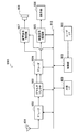
- FIG. 2 is a block diagram illustrating an example of a configuration of an image decoding device 60 that is an aspect of the image processing device according to the present embodiment.
- an accumulation buffer 61 a lossless decoding unit 62, an inverse quantization unit 63, an inverse transformation unit 64, an addition unit 65, a deblock filter 24b, an SAO filter 67, a rearrangement buffer 68, a D / A (Digital to Digital) Analogue) conversion unit 69, frame memory 70, selectors 71a and 71b, intra prediction unit 80, and inter prediction unit 90.
- the accumulation buffer 61 temporarily accumulates an encoded stream received from the image encoding device 10 via a transmission unit (not shown) (for example, a communication interface or a connection interface with peripheral devices) using a storage medium.
- a transmission unit for example, a communication interface or a connection interface with peripheral devices
- the lossless decoding unit 62 decodes the quantized data from the encoded stream input from the accumulation buffer 61 according to the encoding method used at the time of encoding.
- the lossless decoding unit 62 outputs the decoded quantized data to the inverse quantization unit 63.
- the lossless decoding unit 62 decodes various encoding parameters inserted in the header area of the encoded stream.
- the parameters decoded by the lossless decoding unit 62 may include, for example, information related to intra prediction and information related to inter prediction.
- the lossless decoding unit 62 outputs information related to intra prediction to the intra prediction unit 80.
- the lossless decoding unit 62 outputs information related to inter prediction to the inter prediction unit 90.
- the inverse quantization unit 63 inversely quantizes the quantized data input from the lossless decoding unit 62 in the same quantization step as that used for encoding, and restores transform coefficient data.
- the inverse quantization unit 63 outputs the restored transform coefficient data to the inverse transform unit 64.
- the inverse transform unit 64 generates prediction error data by performing inverse transform on the transform coefficient data input from the inverse quantization unit 63 according to the transform method used at the time of encoding.
- the inverse conversion unit 64 outputs the generated prediction error data to the addition unit 65.
- the adding unit 65 generates decoded image data by adding the prediction error data input from the inverse transform unit 64 and the predicted image data input from the selector 71b. Then, the addition unit 65 outputs the generated decoded image data to the deblock filter 24b and the frame memory 70.
- the deblocking filter 24 b reduces the block distortion by filtering the decoded image data input from the adding unit 65, and outputs the decoded image data after filtering to the SAO filter 67.
- the processing by the deblocking filter 24b will be described in detail later.
- the SAO filter 67 removes noise by applying edge offset processing or band offset processing to the decoded image data input from the deblocking filter 24b, and the decoded image data after processing is sent to the rearrangement buffer 68 and the frame memory 70. Output.
- the rearrangement buffer 68 generates a series of time-series image data by rearranging the images input from the SAO filter 67. Then, the rearrangement buffer 68 outputs the generated image data to the D / A conversion unit 69.
- the D / A converter 69 converts the digital image data input from the rearrangement buffer 68 into an analog image signal. Then, the D / A conversion unit 69 displays the decoded video by outputting an analog image signal to a display (not shown) connected to the image decoding device 60, for example.
- the frame memory 70 stores the decoded image data before filtering input from the adding unit 65 and the decoded image data after filtering input from the SAO filter 67 using a storage medium.
- the selector 71a determines the output destination of the image data from the frame memory 70 between the intra prediction unit 80 and the inter prediction unit 90 for each block in the image according to the prediction mode information acquired by the lossless decoding unit 62. Switch. For example, when the intra prediction mode is designated, the selector 71a outputs the decoded image data before filtering supplied from the frame memory 70 to the intra prediction unit 80 as reference image data. In addition, when the inter prediction mode is designated, the selector 71a outputs the filtered decoded image data to the inter prediction unit 90 as reference image data.
- the selector 71b switches the output source of the predicted image data to be supplied to the adding unit 65 between the intra prediction unit 80 and the inter prediction unit 90 according to the prediction mode information acquired by the lossless decoding unit 62. For example, the selector 71b supplies the prediction image data output from the intra prediction unit 80 to the addition unit 65 when the intra prediction mode is designated. Further, when the inter prediction mode is designated, the selector 71b supplies the predicted image data output from the inter prediction unit 90 to the adding unit 65.
- the intra prediction unit 80 performs intra prediction processing based on the information related to intra prediction input from the lossless decoding unit 62 and the reference image data from the frame memory 70, and generates predicted image data. Then, the intra prediction unit 80 outputs the generated predicted image data to the selector 71b.
- the inter prediction unit 90 performs inter prediction processing based on the information related to inter prediction input from the lossless decoding unit 62 and the reference image data from the frame memory 70, and generates predicted image data. Then, the inter prediction unit 90 outputs the generated predicted image data to the selector 71b.
- encoding processing (encoding tool) that is not described in Non-Patent Document 1 is collectively referred to as encoding processing (encoding tool) newly introduced.
- a newly introduced encoding process (encoding tool) is an encoding process (encoding tool) not described in Non-Patent Document 1, and an encoding process described in Non-Patent Document 2 (encoding tool).
- Encoding tool The newly introduced encoding process (encoding tool) is not limited to the encoding process (encoding tool) described in Non-Patent Document 2, and for example, an encoding not described in Non-Patent Document 1
- the encoding process (encoding tool) defined in the Main Profile or Main10 Profile of the HEVC / H.265 standard is collectively referred to as the existing main encoding tool, and HEVC / H
- the encoding process (encoding tool) not defined in the Main Profile or Main 10 Profile of the .265 standard is collectively referred to as the newly introduced main encoding process (encoding tool).
- the encoding process (encoding tool) is described, but it can be similarly applied to a decoding process (decoding tool) corresponding to the encoding process (encoding tool).
- the present invention can be similarly applied to the introduced decoding process (decoding tool) and the newly introduced main decoding process (decoding tool).
- FIG. 3 is an explanatory diagram for explaining an outline of recursive block division for a CU (Coding Unit) in HEVC.
- An entire quadtree is called CTB (Coding Tree Block), and a logical unit corresponding to CTB is called CTU (Coding Tree Unit).
- CTB Coding Tree Block
- CTU Coding Tree Unit
- CU C01 having a size of 64 ⁇ 64 pixels is shown as an example.
- the division depth of CU C01 is equal to zero. This means that CU C01 corresponds to the root of the CTU.
- the size of the CTU or CTB can be specified by a parameter encoded in SPS (Sequence Parameter Set).
- CU C02 is one of four CUs divided from CU C01, and has a size of 32 ⁇ 32 pixels.
- the division depth of CU C02 is equal to 1.
- CU C03 is one of four CUs divided from CU C02, and has a size of 16 ⁇ 16 pixels.
- the division depth of CU C03 is equal to 2.
- CU C04 is one of four CUs divided from CU C03, and has a size of 8 ⁇ 8 pixels.
- the division depth of CU C04 is equal to 3.
- a CU is formed by recursively dividing an image to be encoded.
- the depth of division is variable.
- a larger size (that is, a smaller depth) CU may be set in a flat image region such as a blue sky.
- a CU having a smaller size can be set in a steep image area including many edges.
- Each of the set CUs becomes a processing unit of the encoding process.
- PU Prediction Unit
- a PU is a processing unit of prediction processing including intra prediction and inter prediction.
- a PU is formed by dividing a CU by one of several division patterns.
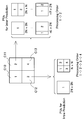
- FIG. 4 is an explanatory diagram for explaining the setting of the PU to the CU shown in FIG. The right side of FIG. 4 shows 8 types of division patterns: 2N ⁇ 2N, 2N ⁇ N, N ⁇ 2N, N ⁇ N, 2N ⁇ nU, 2N ⁇ nD, nL ⁇ 2N, and nR ⁇ 2N. .
- two types of 2N ⁇ 2N and N ⁇ N can be selected for intra prediction (N ⁇ N can be selected only by the SCU).
- the inter prediction all of the eight types of division patterns can be selected when asymmetric motion division is enabled.
- TU Transform Unit
- a TU is formed by dividing a CU (for an intra CU, each PU in the CU) to a certain depth.
- FIG. 5 is an explanatory diagram for describing setting of a TU in the CU illustrated in FIG.
- the right side of FIG. 5 shows one or more TUs that can be set to CU C02.
- TU T01 has a size of 32 ⁇ 32 pixels, and the depth of the TU division is equal to zero.
- TU T02 has a size of 16 ⁇ 16 pixels, and the TU partition depth is equal to 1.
- TU T03 has a size of 8 ⁇ 8 pixels, and the TU partition depth is equal to 2.
- the block division to be performed in order to set the blocks such as CU, PU, and TU in the image is typically determined based on a cost comparison that affects coding efficiency. For example, if the encoder compares the cost between one 2M ⁇ 2M pixel CU and four M ⁇ M pixel CUs, and sets four M ⁇ M pixel CUs, the encoding efficiency is higher. For example, it is determined that a 2M ⁇ 2M pixel CU is divided into four M ⁇ M pixel CUs.
- FIG. 6 is an explanatory diagram for explaining the scanning order of the CU / PU.
- four CUs C10, C11, C12, and C13 that can be included in one CTB are shown.
- the numbers in the frame of each CU express the order of processing.
- the encoding process is executed in the order of the upper left CU C10, the upper right CU C11, the lower left CU C12, and the lower right CU C13.
- the right side of FIG. 6 shows one or more PUs for inter prediction that can be set in the CU C11.
- one or more PUs for intra prediction that can be set in the CU C12 are shown.
- the PU is also scanned from left to right and from top to bottom.
- FIG. 7 is a diagram for explaining the shapes of the CU, PU, and TU in the QTBT.
- the shape of the CU may be not only a square but also a rectangle.
- the CTU (Coding Tree Unit) size is 128x128, the CU size (horizontal size w x vertical size h) is 128x128, 64x64, 32x32, 16x16, 8x8, as shown in FIG.
- Non-Patent Document 2 PU and TU are the same as CU. However, the CU, PU, and TU block structures may be independent. The present technology can be applied not only to a block structure having the same CU, PU, and TU, but also to a block structure having independent CU, PU, and TU.
- Non-Patent Document 2 also describes that block division of a luminance component (Luma) and a color difference component (Chroma) at the time of intra prediction is performed independently.
- block is used as a partial area or processing unit of an image (picture) (not a block of a processing unit).
- the “block” in this case indicates an arbitrary partial area in the picture, and its size, shape, characteristics, and the like are not limited.
- the “block” in this case includes an arbitrary partial area (processing unit) such as TU, PU, CU, CTU, CTB, tile, or slice.
- the block boundary may be any of the above-described block boundaries, for example, a boundary between blocks divided by the above-described block division in HEVC, or a boundary between blocks divided by block division in QTBT. including.
- the present technology can be applied to the block structure and block boundary described in JVET-D0117, “Multi-Type-Tree”.
- AMT and NSST are conversion processes that can be applied by the conversion unit 14 described above, for example.
- AMT is an orthogonal transform process for transforming an image signal in the spatial domain into a frequency domain
- NSST is a transform process that is applied after AMT to increase the degree of concentration of coefficient energy.
- the conversion for example, the above-described AMT
- the conversion to be applied later for example, the above-described NSST
- secondary conversion for example, the above-described NSST
- Primary conversion and secondary conversion are selected from multiple conversion methods.
- the primary transformation identifier for example, Transform Set described in Non-Patent Document 2 related to the selection of primary transformation
- the secondary transformation identifier for example, Non-Patent Document 2 related to the selection of secondary transformation.
- the described NSST index can be specified.
- the conversion unit 14 may apply primary conversion according to the primary conversion identifier, or may apply secondary conversion according to the secondary conversion identifier.
- the conversion part 14 does not need to apply secondary conversion according to a secondary conversion identifier (it may skip).
- block distortion may occur due to different conversion processing applied between blocks. That is, when the primary conversion identifier is different between blocks or when the secondary conversion identifier is different between blocks, block distortion is likely to occur.
- the above-described conversion process can be simplified.
- the short side of the conversion block is a predetermined value (for example, 64) or more
- the conversion process is simplified.
- a predetermined value for example, 64
- a low-frequency component of 32 points is applied (Zero-out).
- the short side of the transform block is greater than or equal to a predetermined value, the secondary transform is applied only to the upper left sub-block of the transform blocks.
- Prediction process newly introduced prediction process
- horizontal / vertical motion prediction processing was employed as prediction processing.
- Intra BC Intra Block Copy
- Affine MC Affine Motion compensation Prediction
- PDPC Position Dependent intra Prediction Combination
- block distortion may be caused by whether or not Intra BC is applied (whether or not it is applied) between blocks.
- Block distortion may occur due to the presence or absence of application of Affine MC (whether or not it is applied) between blocks.
- block distortion may occur due to the presence / absence of application of PDPC (whether it is applied) between blocks.
- encoding processes include the above-described new block structure, new It is not limited to simple conversion processing and new prediction processing.
- a newly introduced encoding process includes a new quantization process, a new filter process, and the like.
- Deblock filter> [3-1. Description of existing processing]
- determination of whether or not to apply a deblocking filter and selection of filter strength are performed based on the boundary strength value bS of the block boundary.
- FIG. 8 is a table for explaining the setting of the boundary strength value bS in HEVC. As shown in FIG. 8, the boundary strength value bS in HEVC can be set according to the following conditions A and B.
- At least one of the two blocks across the block boundary is in the intra prediction mode.
- Condition A is false and at least one of the following conditions B1 and B2 is true.
- B1 A non-zero transform coefficient in at least one of the two blocks sandwiching the block boundary.
- B2 The absolute value of the difference between the motion vectors (MV) of two blocks sandwiching the block boundary is 1 pixel or more, or the reference image for motion compensation is different, or the number of motion vectors (MV) is different
- the boundary strength value bS in HEVC is set to 2 when the condition A is true. Further, the boundary strength value bS in HEVC is set to 1 when the condition B is true. In addition, the boundary strength value bS in HEVC is set to 0 when the conditions A and B are false (that is, when the conditions A, B1, and B2 are all false).
- the luminance component deblocking filter processing can be applied to a block whose boundary strength value bS set as described above is 1 or more. Further, the deblocking filtering process for the color difference component can be applied to the block having the boundary intensity value bS set as 2 as described above.
- the quantization parameter Q related to the luminance component is calculated based on the boundary strength value bS set as described above, and the application of the deblocking filter is required in units of four lines according to the quantization parameter Q. Determination of no or selection of filter strength is performed. Further, as described above, since the deblocking filter processing of the color difference component is applied only when the boundary intensity value bS is 2, the quantization parameter Q regarding the color difference component does not use the boundary intensity value bS. Can be calculated.
- the processing by the deblocking filter 24 includes the above-described setting processing of the boundary strength value bS.
- the deblocking filter 24 determines whether or not the deblocking filter needs to be applied based on the boundary strength value bS, the filter Make strength selection. However, the deblocking filter 24 sets the boundary strength value bS based on information related to the newly introduced encoding process.
- the information related to the newly introduced encoding process may include, for example, information on a conversion identifier (the above-described primary conversion identifier or secondary conversion identifier). Further, the information related to the newly introduced encoding process may include information on whether or not the conversion process is simplified. In addition, the information related to the newly introduced encoding process may include information about whether Intra BC is applied, information about whether Affine MC is applied, and information about whether PDPC is applied.
- the information related to the above-described encoding process may be given in advance, may be provided as an encoding parameter to the deblocking filter 24, or based on the information or the encoding parameter given in advance. May be specified.
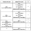
- FIG. 9 is a table for explaining a first example of luminance component boundary strength value setting according to the present embodiment.
- the boundary strength value bS can be set.
- the new conditions shown in FIG. 9 are conditions based on information related to the newly introduced encoding process.
- the range of the boundary strength value bS is expanded so as to be larger (wider) than the range of the boundary strength value bS in the HEVC described with reference to FIG. bS can be set to an extended value (a value that cannot be set in HEVC, and 3 in the example shown in FIG. 9).
- the new condition based on the information relating to the newly introduced encoding process may include the following condition D, condition E, condition F, condition G, and condition H.
- Intra BC is applied differently between two blocks across the block boundary (applies only to one of the blocks)
- F1 Transform Set (primary transform identifier) is different between two blocks that sandwich the block boundary.
- F2 NSST index (secondary conversion identifier) differs between two blocks that sandwich the block boundary.
- F3 Whether or not the conversion process is simplified differs between the two blocks that sandwich the block boundary (in either block) Only the conversion process is simplified)
- the boundary strength value bS is set to 3. Is done. Also, when the existing condition A is true and the new conditions D, E, and F are all false, the boundary strength value bS is set to 2.
- the boundary strength value bS is set to 2 when the existing condition B is true and one of the new conditions G and H is true. The Further, when the existing condition B is true and the new conditions G and H are both false, the boundary strength value bS is set to 1.
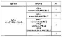
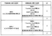
- FIG. 10 is a table for explaining a second example of luminance component boundary strength value setting according to the present embodiment.
- the boundary strength value bS is set according to a combination of a condition related to the prediction process and a condition related to the conversion process.
- the range of the boundary strength value bS is expanded so as to be larger (wider) than the range of the boundary strength value bS in the HEVC described with reference to FIG. It can be set to an extended value (a value that cannot be set in HEVC, 3 or 4 in the example shown in FIG. 10).
- the conditions related to the prediction process include a condition related to the setting of the boundary strength value bS in HEVC and a condition based on information related to the newly introduced encoding process. Also, as shown in FIG. 10, the conditions related to the conversion process are conditions based on information related to the newly introduced encoding process.
- the conditions related to the prediction process may include the following conditions I, J, and K.
- Intra BC is applied differently between two blocks across the block boundary (conditions based on information on newly introduced encoding process)
- Condition I is false and at least one of the two blocks across the block boundary is in the intra prediction mode.
- Condition I and condition J are false, and at least one of the following conditions K1, K2, and K3 is true.
- K1 Of two blocks that sandwich a block boundary, At least one block has a non-zero transform coefficient.
- K2 The absolute value of the difference between the motion vectors (MV) of two blocks sandwiching the block boundary is 1 pixel or more, or the motion compensation reference image is different or motion The number of vectors (MV) is different.
- K3 The presence or absence of application of Affine MC is different between two blocks sandwiching the block boundary (conditions based on information on newly introduced encoding processing)
- the boundary strength value bS is set to 4 when the condition I that is a condition related to the prediction process is true and the condition F that is a condition related to the conversion process is true.
- the boundary strength value bS is set to 3 when the condition I that is a condition related to the prediction process is true and the condition F that is a condition related to the conversion process is false.
- the boundary strength value bS is set to 3 when the condition J that is a condition related to the prediction process is true and the condition F that is a condition related to the conversion process is true.
- the boundary strength value bS is set to 2 when the condition J that is a condition related to the prediction process is true and the condition F that is a condition related to the conversion process is false.
- the boundary strength value bS is set to 2 when the condition K that is a condition related to the prediction process is true and the condition H that is a condition related to the conversion process is true.
- the boundary strength value bS is set to 1 when the condition K that is a condition related to the prediction process is true and the condition H that is a condition related to the conversion process is false.
- the boundary strength value bS is set to 1 when the condition K that is a condition related to the prediction process is false and the condition H that is a condition related to the conversion process is true.
- the boundary strength value bS is set to 0 when the condition K that is a condition related to the prediction process is false and the condition H that is a condition related to the conversion process is false.
- FIG. 11 is a table for explaining a first example of color difference component boundary strength value settings according to the present embodiment.
- the boundary strength value bS is based on the new condition shown in FIG. Can be set.
- the new conditions shown in FIG. 11 correspond to the conditions D, E, and F described with reference to FIG.
- the boundary strength value bS is expanded so that the range of the boundary strength value bS in the HEVC described with reference to FIG. 8 is larger (wider). It can be set to an extended value (a value that cannot be set in HEVC, and 3 in the example shown in FIG. 11).
- the boundary strength value bS is set to 3. Is done. Also, when the existing condition A is true and the new conditions D, E, and F are all false, the boundary strength value bS is set to 2.
- the boundary strength value bS may be set to 0 when the condition A is false.
- FIG. 12 is a table for explaining a second example of setting of the boundary strength value of chrominance component according to the present embodiment.
- the boundary intensity value bS is based on the condition related to the prediction process and the condition related to the conversion process. Is set.
- the boundary strength value bS is expanded so that the range of the boundary strength value bS in the HEVC described with reference to FIG. 8 is larger (wider). It can be set to an extended value (a value that cannot be set in HEVC, 3 or 4 in the example shown in FIG. 12).
- the conditions regarding the prediction process shown in FIG. 12 correspond to the conditions I and J described with reference to FIG. Further, the condition relating to the conversion process shown in FIG. 12 corresponds to the condition F described with reference to FIG.
- the boundary strength value bS is set to 4 when the condition I that is a condition related to the prediction process is true and the condition F that is a condition related to the conversion process is true.
- the boundary strength value bS is set to 3 when the condition I that is a condition related to the prediction process is true and the condition F that is a condition related to the conversion process is false.
- the boundary strength value bS is set to 3 when the condition J that is a condition related to the prediction process is true and the condition F that is a condition related to the conversion process is true.
- the boundary strength value bS is set to 2 when the condition J that is a condition related to the prediction process is true and the condition F that is a condition related to the conversion process is false.
- the color difference component deblocking filter is applied only when the boundary strength value bS is 2 or more, so that the example shown in FIG. 12 is different from the example shown in FIG. Then, the boundary strength value bS may be set to 0 when the conditions I and J are false.
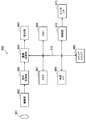
- FIG. 13 is an example of a detailed configuration of the deblocking filter 24 that realizes the setting processing of the boundary strength value bS based on the information related to the newly introduced encoding processing described above.
- FIG. 13 a boundary strength setting unit 110, a filter application determination unit 120, an intensity selection unit 130, a filtering unit 140, and a determination control unit 150 are included.
- the boundary strength setting unit 110 sets the boundary strength value bS based on the information related to the newly introduced encoding process.
- the boundary strength setting unit 110 may set the boundary strength value bS of the luminance component according to the table shown in FIG. 9, or may be set according to the table shown in FIG.
- the boundary strength setting unit 110 may set the boundary strength value bS of the color difference component according to the table shown in FIG. 11 or according to the table shown in FIG.
- the boundary strength setting unit 110 sets the boundary strength value bS based on the information related to the newly introduced encoding process, so that an appropriate data for the block distortion caused by the influence of the newly introduced encoding process can be obtained. It becomes easy to apply the block filter, and the block distortion can be further reduced.
- boundary strength value bS set by the boundary strength setting unit 110 is provided to the determination control unit 150, and is used for determining whether or not to apply a deblocking filter in units of boundaries.
- the filter application determination unit 120 determines whether or not to apply the deblocking filter to two adjacent blocks adjacent to each other across the boundary in units of four lines orthogonal to the block boundary (application necessity). For example, the filter application determination unit 120 may determine whether to apply the deblocking filter with reference to the pixel values of the first line and the fourth line. Further, the determination as to whether the deblocking filter application is necessary by the filter application determination unit 120 may be performed based on the quantization parameter Q calculated using the boundary strength value bS.
- the quantization parameter Q related to the luminance component is calculated by the following equation using the average value qP L of the quantization parameter related to the luminance component, the boundary strength value bS related to the luminance component, and slice_tc_offset_div2 that is the offset value.
- Clip 3 (a, b, c) represents a process of clipping the value c in the range of a ⁇ c ⁇ b.
- the quantization parameter Q related to the color difference component is calculated without using the boundary strength value bS.
- the quantization parameter Q related to the color difference component since the range of the boundary strength value bS is expanded so that the boundary strength value bS can be set to a value larger than 2, the quantization parameter Q related to the color difference component also includes the boundary strength. It is desirable to calculate using the value bS.
- the quantization parameter Q related to the color difference component is calculated by the following equation using the average value qP C of the quantization parameter related to the color difference component, the boundary intensity value bS related to the color difference component, and slice_tc_offset_div2 that is the offset value. May be.
- quantization parameter Q related to the color difference component is not limited to the calculation of the above equation, and may be calculated as the following equation.
- the filter application determination unit 120 calculates the quantization parameter Q related to the chrominance component based on the boundary intensity value bS related to the chrominance component, so that the deblocking filter can be more appropriately applied and block distortion can be reduced. It becomes possible to reduce more.
- the filter application determination unit 120 may determine whether to apply the deblocking filter in units of four lines based on the quantization parameter Q obtained as described above.
- the determination of whether or not to apply a deblocking filter in units of four lines based on the quantization parameter Q is the same as the determination of whether or not to apply a deblocking filter in units of four lines in HEVC described in Non-Patent Document 1. Also good.
- the filter application determination unit 120 causes, for example, filter strength selection by the strength selection unit 130 and filtering by the filtering unit 140 to be performed on block boundaries that satisfy the application conditions of the deblocking filter. On the other hand, the filter application determination unit 120 skips the filter strength selection by the strength selection unit 130 and the filtering by the filtering unit 140 for the block boundary that does not satisfy the deblocking filter application condition.
- the strength selection unit 130 selects the strength of the deblocking filter applied to the block boundary by the filtering unit 140. More specifically, the strength selection unit 130 selects the filter strength for the block boundary determined by the filter application determination unit 120 to apply the deblocking filter. Note that the selection of the filter strength by the strength selection unit 130 may be performed based on the quantization parameter Q calculated using the boundary strength value bS. Then, the strength selection unit 130 outputs information indicating the selected filter strength to the filtering unit 140.
- the filtering unit 140 deblocks luminance components and color difference components of pixels located near the block boundary. Apply a filter.
- the filter configuration of the filtering unit 140 may be the same as the filter in the HEVC described in Non-Patent Document 1.
- the filtering unit 140 applies the deblocking filter to a block boundary that is determined by the filter application determining unit 120 to apply the deblocking filter.
- the filtering unit 140 sequentially outputs the pixel value after filtering for the pixel to which the filter is applied and the pixel value of the input image for the other pixels as the pixel value of the output image.
- the determination control unit 150 controls determination of whether or not to apply the deblocking filter. For example, the determination control unit 150 determines whether or not to apply a deblocking filter for each boundary according to the boundary strength value bS set by the boundary strength setting unit 110.
- the determination control unit 150 skips the filter application determination unit 120 from determining whether the deblocking filter needs to be applied to a boundary whose boundary strength value bS related to the luminance component set by the boundary strength setting unit 110 is 0. You may let them. Further, the determination control unit 150 determines whether or not the deblocking filter application is necessary for the filter application determination unit 120 for a boundary whose boundary strength value bS related to the color difference component set by the boundary strength setting unit 110 is less than 2. It may be skipped.
- FIG. 14 is a flowchart illustrating an example of a process flow by the deblocking filter 24 according to an embodiment of the present disclosure. The processing from step S110 to step S180 in FIG. 14 is repeated for each of all the boundaries in the input image.
- the boundary strength setting unit 110 sets a boundary strength value bS for one boundary to be processed (hereinafter referred to as an attention boundary) based on information relating to a newly introduced encoding process (S110).
- the determination control unit 150 determines whether or not to apply a deblocking filter for each boundary according to the boundary strength value bS set by the boundary strength setting unit 110 (step S120). Here, if the determination unit for the boundary unit is not satisfied, the subsequent processing from step S130 to step S170 is skipped. On the other hand, if the determination condition for the boundary unit is satisfied, the process proceeds to step S130.
- step S130 the filter application determination unit 120 calculates the quantization parameter Q using the boundary strength value bS.
- the calculation of the quantization parameter Q may be performed by a unit other than the filter application determination unit 120.
- step S140 the filter application determination unit 120 determines whether to apply the deblocking filter (application necessity) in units of four lines orthogonal to the target boundary.
- the filter application determination unit 120 may determine whether to apply the deblocking filter with reference to the pixel values of the first line and the fourth line of the four lines.
- the subsequent processing in step S150 and step S160 is skipped.
- the deblocking filter application condition is satisfied, the process proceeds to step S150.
- step S150 the strength selection unit 130 selects the strength of the filter to be applied to the target boundary (step S150).
- the filtering unit 140 applies a deblocking filter to the target boundary (step S160).
- step S170 if an unprocessed boundary remains in the input image (YES in step S170), a new attention boundary is set, and the process returns to step S110. If there is no unprocessed boundary left, the process for the input image ends.
- Hardware configuration example> The series of processes described above can be executed by hardware or can be executed by software.
- a program constituting the software is installed in the computer.
- the computer includes, for example, a general-purpose personal computer that can execute various functions by installing a computer incorporated in dedicated hardware and various programs.
- FIG. 15 is a block diagram showing an example of the hardware configuration of a computer that executes the above-described series of processing by a program.
- a CPU Central Processing Unit
- ROM Read Only Memory
- RAM Random Access Memory
- An input / output interface 810 is also connected to the bus 804.
- An input unit 811, an output unit 812, a storage unit 813, a communication unit 814, and a drive 815 are connected to the input / output interface 810.
- the input unit 811 includes, for example, a keyboard, a mouse, a microphone, a touch panel, an input terminal, and the like.
- the output unit 812 includes, for example, a display, a speaker, an output terminal, and the like.
- the storage unit 813 includes, for example, a hard disk, a RAM disk, a nonvolatile memory, and the like.
- the communication unit 814 includes a network interface, for example.
- the drive 815 drives a removable medium 821 such as a magnetic disk, an optical disk, a magneto-optical disk, or a semiconductor memory.
- the CPU 801 loads the program stored in the storage unit 813 into the RAM 803 via the input / output interface 810 and the bus 804 and executes the program, for example. Is performed.
- the RAM 803 also appropriately stores data necessary for the CPU 801 to execute various processes.
- the program executed by the computer (CPU 801) can be recorded and applied to, for example, a removable medium 821 as a package medium or the like.
- the program can be installed in the storage unit 813 via the input / output interface 810 by attaching the removable medium 821 to the drive 815.
- This program can also be provided via a wired or wireless transmission medium such as a local area network, the Internet, or digital satellite broadcasting. In that case, the program can be received by the communication unit 814 and installed in the storage unit 813.
- a wired or wireless transmission medium such as a local area network, the Internet, or digital satellite broadcasting.
- the program can be received by the communication unit 814 and installed in the storage unit 813.
- this program can be installed in advance in the ROM 802 or the storage unit 813.
- the image encoding device 10 and the image decoding device 60 are a transmitter or a receiver in satellite broadcasting, cable broadcasting such as cable TV, distribution on the Internet, and distribution to terminals by cellular communication,
- the present invention can be applied to various electronic devices such as a recording device that records an image on a medium such as an optical disk, a magnetic disk, and a flash memory, or a playback device that reproduces an image from these storage media.
- FIG. 16 shows an example of a schematic configuration of a television device to which the above-described embodiment is applied.
- the television device 900 includes an antenna 901, a tuner 902, a demultiplexer 903, a decoder 904, a video signal processing unit 905, a display unit 906, an audio signal processing unit 907, a speaker 908, an external interface (I / F) 909, and a control unit 910.
- Tuner 902 extracts a signal of a desired channel from a broadcast signal received via antenna 901, and demodulates the extracted signal. Then, the tuner 902 outputs the encoded bit stream obtained by the demodulation to the demultiplexer 903. That is, the tuner 902 has a role as a transmission unit in the television device 900 that receives an encoded stream in which an image is encoded.
- the demultiplexer 903 separates the video stream and audio stream of the viewing target program from the encoded bit stream, and outputs each separated stream to the decoder 904. In addition, the demultiplexer 903 extracts auxiliary data such as EPG (Electronic Program Guide) from the encoded bit stream, and supplies the extracted data to the control unit 910. Note that the demultiplexer 903 may perform descrambling when the encoded bit stream is scrambled.
- EPG Electronic Program Guide
- the decoder 904 decodes the video stream and audio stream input from the demultiplexer 903. Then, the decoder 904 outputs the video data generated by the decoding process to the video signal processing unit 905. In addition, the decoder 904 outputs audio data generated by the decoding process to the audio signal processing unit 907.
- the video signal processing unit 905 reproduces the video data input from the decoder 904 and causes the display unit 906 to display the video.
- the video signal processing unit 905 may cause the display unit 906 to display an application screen supplied via a network.
- the video signal processing unit 905 may perform additional processing such as noise removal on the video data according to the setting.
- the video signal processing unit 905 may generate a GUI (Graphical User Interface) image such as a menu, a button, or a cursor, and superimpose the generated image on the output image.
- GUI Graphic User Interface
- the display unit 906 is driven by a drive signal supplied from the video signal processing unit 905, and displays video on a video screen of a display device (for example, a liquid crystal display, a plasma display, or an OELD (Organic ElectroLuminescence Display) (organic EL display)). Or an image is displayed.
- a display device for example, a liquid crystal display, a plasma display, or an OELD (Organic ElectroLuminescence Display) (organic EL display)). Or an image is displayed.
- the audio signal processing unit 907 performs reproduction processing such as D / A conversion and amplification on the audio data input from the decoder 904, and outputs audio from the speaker 908.
- the audio signal processing unit 907 may perform additional processing such as noise removal on the audio data.
- the external interface 909 is an interface for connecting the television apparatus 900 to an external device or a network.
- a video stream or an audio stream received via the external interface 909 may be decoded by the decoder 904. That is, the external interface 909 also has a role as a transmission unit in the television apparatus 900 that receives an encoded stream in which an image is encoded.
- the control unit 910 includes a processor such as a CPU and memories such as a RAM and a ROM.
- the memory stores a program executed by the CPU, program data, EPG data, data acquired via a network, and the like.
- the program stored in the memory is read and executed by the CPU when the television apparatus 900 is activated.
- the CPU controls the operation of the television device 900 according to an operation signal input from the user interface unit 911 by executing the program.
- the user interface unit 911 is connected to the control unit 910.
- the user interface unit 911 includes, for example, buttons and switches for the user to operate the television device 900, a remote control signal receiving unit, and the like.
- the user interface unit 911 detects an operation by the user via these components, generates an operation signal, and outputs the generated operation signal to the control unit 910.
- the bus 912 connects the tuner 902, the demultiplexer 903, the decoder 904, the video signal processing unit 905, the audio signal processing unit 907, the external interface 909, and the control unit 910 to each other.
- the decoder 904 may have the function of the image decoding apparatus 60 described above. That is, the decoder 904 may decode the encoded data by the method described in each of the above embodiments. By doing in this way, the television apparatus 900 can further reduce block distortion.
- the video signal processing unit 905 encodes the image data supplied from the decoder 904, for example, and the obtained encoded data is transmitted to the television via the external interface 909. It may be possible to output to the outside of the John apparatus 900.
- the video signal processing unit 905 may have the function of the image encoding device 10 described above. That is, the video signal processing unit 905 may encode the image data supplied from the decoder 904 by the method described in the above embodiments. By doing in this way, the television apparatus 900 can further reduce block distortion.
- FIG. 17 shows an example of a schematic configuration of a mobile phone to which the above-described embodiment is applied.
- a cellular phone 920 includes an antenna 921, a communication unit 922, an audio codec 923, a speaker 924, a microphone 925, a camera unit 926, an image processing unit 927, a demultiplexing unit 928, a recording / reproducing unit 929, a display unit 930, a control unit 931, an operation A portion 932 and a bus 933.
- the antenna 921 is connected to the communication unit 922.
- the speaker 924 and the microphone 925 are connected to the audio codec 923.
- the operation unit 932 is connected to the control unit 931.
- the bus 933 connects the communication unit 922, the audio codec 923, the camera unit 926, the image processing unit 927, the demultiplexing unit 928, the recording / reproducing unit 929, the display unit 930, and the control unit 931 to each other.
- the mobile phone 920 has various operation modes including a voice call mode, a data communication mode, a shooting mode, and a videophone mode, and is used for sending and receiving voice signals, sending and receiving e-mail or image data, taking images, and recording data. Perform the action.
- the analog voice signal generated by the microphone 925 is supplied to the voice codec 923.
- the audio codec 923 converts an analog audio signal into audio data, A / D converts the compressed audio data, and compresses it. Then, the audio codec 923 outputs the compressed audio data to the communication unit 922.
- the communication unit 922 encodes and modulates the audio data and generates a transmission signal. Then, the communication unit 922 transmits the generated transmission signal to a base station (not shown) via the antenna 921. In addition, the communication unit 922 amplifies a radio signal received via the antenna 921 and performs frequency conversion to acquire a received signal.
- the communication unit 922 demodulates and decodes the received signal to generate audio data, and outputs the generated audio data to the audio codec 923.
- the audio codec 923 decompresses the audio data and performs D / A conversion to generate an analog audio signal. Then, the audio codec 923 supplies the generated audio signal to the speaker 924 to output audio.
- the control unit 931 generates character data constituting the e-mail in response to an operation by the user via the operation unit 932.
- the control unit 931 causes the display unit 930 to display characters.
- the control unit 931 generates e-mail data in response to a transmission instruction from the user via the operation unit 932, and outputs the generated e-mail data to the communication unit 922.
- the communication unit 922 encodes and modulates email data and generates a transmission signal. Then, the communication unit 922 transmits the generated transmission signal to a base station (not shown) via the antenna 921.
- the communication unit 922 amplifies a radio signal received via the antenna 921 and performs frequency conversion to acquire a received signal.
- the communication unit 922 demodulates and decodes the received signal to restore the email data, and outputs the restored email data to the control unit 931.
- the control unit 931 displays the content of the electronic mail on the display unit 930, supplies the electronic mail data to the recording / reproducing unit 929, and writes the data in the storage medium.
- the recording / reproducing unit 929 has an arbitrary readable / writable storage medium.
- the storage medium may be a built-in storage medium such as a RAM or a flash memory, or an externally mounted type such as a hard disk, a magnetic disk, a magneto-optical disk, an optical disk, a USB (Universal Serial Bus) memory, or a memory card. It may be a storage medium.
- the camera unit 926 images a subject to generate image data, and outputs the generated image data to the image processing unit 927.
- the image processing unit 927 encodes the image data input from the camera unit 926, supplies the encoded stream to the recording / reproducing unit 929, and writes the encoded stream in the storage medium.
- the recording / reproducing unit 929 reads out the encoded stream recorded in the storage medium and outputs the encoded stream to the image processing unit 927.
- the image processing unit 927 decodes the encoded stream input from the recording / reproducing unit 929, supplies the image data to the display unit 930, and displays the image.
- the demultiplexing unit 928 multiplexes the video stream encoded by the image processing unit 927 and the audio stream input from the audio codec 923, and the multiplexed stream is the communication unit 922. Output to.
- the communication unit 922 encodes and modulates the stream and generates a transmission signal. Then, the communication unit 922 transmits the generated transmission signal to a base station (not shown) via the antenna 921.
- the communication unit 922 amplifies a radio signal received via the antenna 921 and performs frequency conversion to acquire a received signal.
- These transmission signal and reception signal may include an encoded bit stream.
- the communication unit 922 demodulates and decodes the received signal to restore the stream, and outputs the restored stream to the demultiplexing unit 928.
- the demultiplexing unit 928 separates the video stream and the audio stream from the input stream, and outputs the video stream to the image processing unit 927 and the audio stream to the audio codec 923.
- the image processing unit 927 decodes the video stream and generates video data.
- the video data is supplied to the display unit 930, and a series of images is displayed on the display unit 930.
- the audio codec 923 decompresses the audio stream and performs D / A conversion to generate an analog audio signal. Then, the audio codec 923 supplies the generated audio signal to the speaker 924 to output audio.
- the image processing unit 927 may have the function of the image encoding device 10 described above. That is, the image processing unit 927 may encode the image data by the method described in each of the above embodiments. By doing so, the cellular phone 920 can further reduce block distortion.
- the image processing unit 927 may have the function of the image decoding device 60 described above. That is, the image processing unit 927 may decode the encoded data by the method described in each of the above embodiments. By doing so, the cellular phone 920 can further reduce block distortion.
- FIG. 18 shows an example of a schematic configuration of a recording / reproducing device to which the above-described embodiment is applied.
- the recording / reproducing device 940 encodes audio data and video data of a received broadcast program and records the encoded data on a recording medium.
- the recording / reproducing device 940 may encode audio data and video data acquired from another device and record them on a recording medium, for example.
- the recording / reproducing device 940 reproduces data recorded on the recording medium on a monitor and a speaker, for example, in accordance with a user instruction. At this time, the recording / reproducing device 940 decodes the audio data and the video data.
- the recording / reproducing apparatus 940 includes a tuner 941, an external interface 942, an encoder 943, an HDD (Hard Disk Drive) 944, a disk drive 945, a selector 946, a decoder 947, an OSD (On-Screen Display) 948, a control unit 949, and a user interface. 950.
- Tuner 941 extracts a signal of a desired channel from a broadcast signal received via an antenna (not shown), and demodulates the extracted signal. Then, the tuner 941 outputs the encoded bit stream obtained by the demodulation to the selector 946. That is, the tuner 941 has a role as a transmission unit in the recording / reproducing apparatus 940.
- the external interface 942 is an interface for connecting the recording / reproducing apparatus 940 to an external device or a network.
- the external interface 942 may be, for example, an IEEE 1394 interface, a network interface, a USB interface, or a flash memory interface.
- video data and audio data received via the external interface 942 are input to the encoder 943. That is, the external interface 942 serves as a transmission unit in the recording / reproducing device 940.
- the encoder 943 encodes video data and audio data when the video data and audio data input from the external interface 942 are not encoded. Then, the encoder 943 outputs the encoded bit stream to the selector 946.
- the HDD 944 records an encoded bit stream in which content data such as video and audio is compressed, various programs, and other data on an internal hard disk. Also, the HDD 944 reads out these data from the hard disk when playing back video and audio.
- the disk drive 945 performs recording and reading of data to and from the mounted recording medium.
- the recording medium loaded in the disk drive 945 may be, for example, a DVD disk (DVD-Video, DVD-RAM, DVD-R, DVD-RW, DVD + R, DVD + RW, etc.) or a Blu-ray (registered trademark) disk. .
- the selector 946 selects an encoded bit stream input from the tuner 941 or the encoder 943 when recording video and audio, and outputs the selected encoded bit stream to the HDD 944 or the disk drive 945. In addition, the selector 946 outputs the encoded bit stream input from the HDD 944 or the disk drive 945 to the decoder 947 during video and audio reproduction.
- the decoder 947 decodes the encoded bit stream and generates video data and audio data. Then, the decoder 947 outputs the generated video data to the OSD 948. The decoder 904 outputs the generated audio data to an external speaker.
- the OSD 948 reproduces the video data input from the decoder 947 and displays the video. Further, the OSD 948 may superimpose a GUI image such as a menu, a button, or a cursor on the video to be displayed.
- a GUI image such as a menu, a button, or a cursor
- the control unit 949 includes a processor such as a CPU and memories such as a RAM and a ROM.
- the memory stores a program executed by the CPU, program data, and the like.
- the program stored in the memory is read and executed by the CPU when the recording / reproducing apparatus 940 is activated, for example.
- the CPU controls the operation of the recording / reproducing device 940 according to an operation signal input from the user interface 950, for example, by executing the program.
- the user interface 950 is connected to the control unit 949.
- the user interface 950 includes, for example, buttons and switches for the user to operate the recording / reproducing device 940, a remote control signal receiving unit, and the like.
- the user interface 950 detects an operation by the user via these components, generates an operation signal, and outputs the generated operation signal to the control unit 949.
- the encoder 943 has the function of the image encoding apparatus 10 according to the above-described embodiment.
- the decoder 947 has the function of the image decoding device 60 according to the above-described embodiment. Thereby, the recording / reproducing apparatus 940 can reduce block distortion more.
- FIG. 19 illustrates an example of a schematic configuration of an imaging device to which the above-described embodiment is applied.
- the imaging device 960 images a subject to generate an image, encodes the image data, and records it on a recording medium.
- the imaging device 960 includes an optical block 961, an imaging unit 962, a signal processing unit 963, an image processing unit 964, a display unit 965, an external interface 966, a memory 967, a media drive 968, an OSD 969, a control unit 970, a user interface 971, and a bus. 972.
- the optical block 961 is connected to the imaging unit 962.
- the imaging unit 962 is connected to the signal processing unit 963.
- the display unit 965 is connected to the image processing unit 964.
- the user interface 971 is connected to the control unit 970.
- the bus 972 connects the image processing unit 964, the external interface 966, the memory 967, the media drive 968, the OSD 969, and the control unit 970 to each other.
- the optical block 961 includes a focus lens and a diaphragm mechanism.
- the optical block 961 forms an optical image of the subject on the imaging surface of the imaging unit 962.
- the imaging unit 962 includes an image sensor such as a CCD or a CMOS, and converts an optical image formed on the imaging surface into an image signal as an electrical signal by photoelectric conversion. Then, the imaging unit 962 outputs the image signal to the signal processing unit 963.
- the signal processing unit 963 performs various camera signal processing such as knee correction, gamma correction, and color correction on the image signal input from the imaging unit 962.
- the signal processing unit 963 outputs the image data after the camera signal processing to the image processing unit 964.
- the image processing unit 964 encodes the image data input from the signal processing unit 963 and generates encoded data. Then, the image processing unit 964 outputs the generated encoded data to the external interface 966 or the media drive 968. The image processing unit 964 also decodes encoded data input from the external interface 966 or the media drive 968 to generate image data. Then, the image processing unit 964 outputs the generated image data to the display unit 965. In addition, the image processing unit 964 may display the image by outputting the image data input from the signal processing unit 963 to the display unit 965. Further, the image processing unit 964 may superimpose display data acquired from the OSD 969 on an image output to the display unit 965.
- the OSD 969 generates a GUI image such as a menu, a button, or a cursor, for example, and outputs the generated image to the image processing unit 964.
- the external interface 966 is configured as a USB input / output terminal, for example.
- the external interface 966 connects the imaging device 960 and a printer, for example, when printing an image.
- a drive is connected to the external interface 966 as necessary.
- a removable medium such as a magnetic disk or an optical disk is attached to the drive, and a program read from the removable medium can be installed in the imaging device 960.
- the external interface 966 may be configured as a network interface connected to a network such as a LAN or the Internet. That is, the external interface 966 has a role as a transmission unit in the imaging device 960.
- the recording medium mounted on the media drive 968 may be any readable / writable removable medium such as a magnetic disk, a magneto-optical disk, an optical disk, or a semiconductor memory. Further, a recording medium may be fixedly attached to the media drive 968, and a non-portable storage unit such as an internal hard disk drive or an SSD (Solid State Drive) may be configured.
- a non-portable storage unit such as an internal hard disk drive or an SSD (Solid State Drive) may be configured.
- the control unit 970 includes a processor such as a CPU and memories such as a RAM and a ROM.
- the memory stores a program executed by the CPU, program data, and the like.
- the program stored in the memory is read and executed by the CPU when the imaging device 960 is activated, for example.
- the CPU controls the operation of the imaging device 960 according to an operation signal input from the user interface 971, for example, by executing the program.
- the user interface 971 is connected to the control unit 970.
- the user interface 971 includes, for example, buttons and switches for the user to operate the imaging device 960.
- the user interface 971 detects an operation by the user via these components, generates an operation signal, and outputs the generated operation signal to the control unit 970.
- the image processing unit 964 has the functions of the image encoding device 10 and the image decoding device 60 according to the above-described embodiment. Thereby, the imaging device 960 can further reduce block distortion.
- the present technology can be applied to any configuration installed in an arbitrary device or a device constituting the system, such as a processor as a system LSI (Large Scale Integration), a plurality of processors, and the like. It is also possible to implement as a module using a plurality of modules, a unit using a plurality of modules, etc., a set in which other functions are further added to the unit, or the like (that is, a partial configuration of the apparatus).
- FIG. 20 illustrates an example of a schematic configuration of a video set to which the present technology is applied.
- the video set 1300 shown in FIG. 20 has such a multi-functional configuration, and a device having a function relating to image encoding and decoding (either or both of them) can be used for the function. It is a combination of devices having other related functions.
- the video set 1300 includes a module group such as a video module 1311, an external memory 1312, a power management module 1313, and a front-end module 1314, and a connectivity 1321, a camera 1322, and a sensor 1323. And a device having a function.
- a module is a component that has several functions that are related to each other and that has a coherent function.
- the specific physical configuration is arbitrary. For example, a plurality of processors each having a function, electronic circuit elements such as resistors and capacitors, and other devices arranged on a wiring board or the like can be considered. . It is also possible to combine the module with another module, a processor, or the like to form a new module.
- the video module 1311 is a combination of configurations having functions related to image processing, and includes an application processor, a video processor, a broadband modem 1333, and an RF module 1334.
- a processor is a configuration in which a configuration having a predetermined function is integrated on a semiconductor chip by an SoC (System On a Chip), and for example, there is one called a system LSI (Large Scale Integration).
- the configuration having the predetermined function may be a logic circuit (hardware configuration), a CPU, a ROM, a RAM, and the like, and a program (software configuration) executed using them. , Or a combination of both.
- a processor has a logic circuit and a CPU, ROM, RAM, etc., a part of the function is realized by a logic circuit (hardware configuration), and other functions are executed by the CPU (software configuration) It may be realized by.
- the 20 is a processor that executes an application relating to image processing.
- the application executed in the application processor 1331 not only performs arithmetic processing to realize a predetermined function, but also can control the internal and external configurations of the video module 1311 such as the video processor 1332 as necessary. .
- the video processor 1332 is a processor having a function related to image encoding / decoding (one or both of them).
- the broadband modem 1333 converts the data (digital signal) transmitted by wired or wireless (or both) broadband communication via a broadband line such as the Internet or a public telephone line network into an analog signal by digitally modulating the data.
- the analog signal received by the broadband communication is demodulated and converted into data (digital signal).
- the broadband modem 1333 processes arbitrary information such as image data processed by the video processor 1332, a stream obtained by encoding the image data, an application program, setting data, and the like.
- the RF module 1334 is a module that performs frequency conversion, modulation / demodulation, amplification, filter processing, and the like on an RF (Radio Frequency) signal transmitted / received via an antenna. For example, the RF module 1334 generates an RF signal by performing frequency conversion or the like on the baseband signal generated by the broadband modem 1333. Further, for example, the RF module 1334 generates a baseband signal by performing frequency conversion or the like on the RF signal received via the front end module 1314.
- RF Radio Frequency
- the application processor 1331 and the video processor 1332 may be integrated and configured as one processor.
- the external memory 1312 is a module that is provided outside the video module 1311 and has a storage device used by the video module 1311.
- the storage device of the external memory 1312 may be realized by any physical configuration, but is generally used for storing a large amount of data such as image data in units of frames. For example, it is desirable to realize with a relatively inexpensive and large-capacity semiconductor memory such as DRAM (Dynamic Random Access Memory).
- the power management module 1313 manages and controls power supply to the video module 1311 (each component in the video module 1311).
- the front-end module 1314 is a module that provides the RF module 1334 with a front-end function (circuit on the transmitting / receiving end on the antenna side). As illustrated in FIG. 20, the front end module 1314 includes, for example, an antenna unit 1351, a filter 1352, and an amplification unit 1353.
- the antenna unit 1351 has an antenna for transmitting and receiving a radio signal and its peripheral configuration.
- the antenna unit 1351 transmits the signal supplied from the amplification unit 1353 as a radio signal, and supplies the received radio signal to the filter 1352 as an electric signal (RF signal).
- the filter 1352 performs a filtering process on the RF signal received via the antenna unit 1351 and supplies the processed RF signal to the RF module 1334.
- the amplifying unit 1353 amplifies the RF signal supplied from the RF module 1334 and supplies the amplified RF signal to the antenna unit 1351.
- Connectivity 1321 is a module having a function related to connection with the outside.
- the physical configuration of the connectivity 1321 is arbitrary.
- the connectivity 1321 has a configuration having a communication function other than the communication standard supported by the broadband modem 1333, an external input / output terminal, and the like.
- the communication 1321 conforms to wireless communication standards such as Bluetooth (registered trademark), IEEE 802.11 (for example, Wi-Fi (Wireless Fidelity, registered trademark)), NFC (Near Field Communication), IrDA (InfraRed Data Association), etc. You may make it have a module which has a function, an antenna etc. which transmit / receive the signal based on the standard.
- the connectivity 1321 has a module having a communication function compliant with a wired communication standard such as USB (Universal Serial Bus), HDMI (registered trademark) (High-Definition Multimedia Interface), and a terminal compliant with the standard. You may do it.
- the connectivity 1321 may have other data (signal) transmission functions such as analog input / output terminals.
- the connectivity 1321 may include a data (signal) transmission destination device.
- the connectivity 1321 reads and writes data to and from a recording medium such as a magnetic disk, an optical disk, a magneto-optical disk, or a semiconductor memory (not only a removable media drive, but also a hard disk, SSD (Solid State Drive) NAS (including Network Attached Storage).
- the connectivity 1321 may include an image or audio output device (a monitor, a speaker, or the like).
- the camera 1322 is a module having a function of capturing a subject and obtaining image data of the subject.
- Image data obtained by imaging by the camera 1322 is supplied to, for example, a video processor 1332 and encoded.
- the sensor 1323 includes, for example, a voice sensor, an ultrasonic sensor, an optical sensor, an illuminance sensor, an infrared sensor, an image sensor, a rotation sensor, an angle sensor, an angular velocity sensor, a velocity sensor, an acceleration sensor, an inclination sensor, a magnetic identification sensor, an impact sensor, It is a module having an arbitrary sensor function such as a temperature sensor.
- the data detected by the sensor 1323 is supplied to the application processor 1331 and used by an application or the like.
- the configuration described as a module in the above may be realized as a processor, or conversely, the configuration described as a processor may be realized as a module.
- the present technology can be applied to the video processor 1332 as described later. Therefore, the video set 1300 can be implemented as a set to which the present technology is applied.
- FIG. 21 illustrates an example of a schematic configuration of a video processor 1332 (FIG. 20) to which the present technology is applied.
- the video processor 1332 receives the video signal and the audio signal, encodes them in a predetermined method, decodes the encoded video data and audio data, A function of reproducing and outputting an audio signal.
- the video processor 1332 includes a video input processing unit 1401, a first image scaling unit 1402, a second image scaling unit 1403, a video output processing unit 1404, a frame memory 1405, and a memory control unit 1406.
- the video processor 1332 includes an encoding / decoding engine 1407, video ES (Elementary Stream) buffers 1408A and 1408B, and audio ES buffers 1409A and 1409B.
- the video processor 1332 includes an audio encoder 1410, an audio decoder 1411, a multiplexing unit (MUX (Multiplexer)) 1412, a demultiplexing unit (DMUX (Demultiplexer)) 1413, and a stream buffer 1414.
- MUX Multiplexing unit
- DMUX demultiplexing unit
- the video input processing unit 1401 acquires a video signal input from, for example, the connectivity 1321 (FIG. 20) and converts it into digital image data.
- the first image enlargement / reduction unit 1402 performs format conversion, image enlargement / reduction processing, and the like on the image data.
- the second image enlargement / reduction unit 1403 performs image enlargement / reduction processing on the image data in accordance with the format of the output destination via the video output processing unit 1404, or is the same as the first image enlargement / reduction unit 1402. Format conversion and image enlargement / reduction processing.
- the video output processing unit 1404 performs format conversion, conversion to an analog signal, and the like on the image data and outputs the reproduced video signal to, for example, the connectivity 1321 or the like.
- the frame memory 1405 is a memory for image data shared by the video input processing unit 1401, the first image scaling unit 1402, the second image scaling unit 1403, the video output processing unit 1404, and the encoding / decoding engine 1407. .
- the frame memory 1405 is realized as a semiconductor memory such as a DRAM, for example.
- the memory control unit 1406 receives the synchronization signal from the encoding / decoding engine 1407, and controls the write / read access to the frame memory 1405 according to the access schedule to the frame memory 1405 written in the access management table 1406A.
- the access management table 1406A is updated by the memory control unit 1406 in accordance with processing executed by the encoding / decoding engine 1407, the first image enlargement / reduction unit 1402, the second image enlargement / reduction unit 1403, and the like.
- the encoding / decoding engine 1407 performs encoding processing of image data and decoding processing of a video stream that is data obtained by encoding the image data. For example, the encoding / decoding engine 1407 encodes the image data read from the frame memory 1405 and sequentially writes the data as a video stream in the video ES buffer 1408A. Further, for example, the video stream is sequentially read from the video ES buffer 1408B, decoded, and sequentially written in the frame memory 1405 as image data.
- the encoding / decoding engine 1407 uses the frame memory 1405 as a work area in the encoding and decoding. Also, the encoding / decoding engine 1407 outputs a synchronization signal to the memory control unit 1406, for example, at a timing at which processing for each macroblock is started.
- the video ES buffer 1408A buffers the video stream generated by the encoding / decoding engine 1407 and supplies the buffered video stream to the multiplexing unit (MUX) 1412.
- the video ES buffer 1408B buffers the video stream supplied from the demultiplexer (DMUX) 1413 and supplies the buffered video stream to the encoding / decoding engine 1407.
- the audio ES buffer 1409A buffers the audio stream generated by the audio encoder 1410 and supplies the buffered audio stream to the multiplexing unit (MUX) 1412.
- the audio ES buffer 1409B buffers the audio stream supplied from the demultiplexer (DMUX) 1413 and supplies the buffered audio stream to the audio decoder 1411.
- the audio encoder 1410 converts, for example, an audio signal input from the connectivity 1321, for example, into a digital signal, and encodes the signal using a predetermined method such as an MPEG audio method or an AC3 (AudioCode number 3) method.
- the audio encoder 1410 sequentially writes an audio stream, which is data obtained by encoding an audio signal, in the audio ES buffer 1409A.
- the audio decoder 1411 decodes the audio stream supplied from the audio ES buffer 1409B, performs conversion to an analog signal, for example, and supplies the reproduced audio signal to, for example, the connectivity 1321 or the like.
- the multiplexing unit (MUX) 1412 multiplexes the video stream and the audio stream.
- the multiplexing method (that is, the format of the bit stream generated by multiplexing) is arbitrary.
- the multiplexing unit (MUX) 1412 can also add predetermined header information or the like to the bit stream. That is, the multiplexing unit (MUX) 1412 can convert the stream format by multiplexing. For example, the multiplexing unit (MUX) 1412 multiplexes the video stream and the audio stream to convert it into a transport stream that is a bit stream in a transfer format. Further, for example, the multiplexing unit (MUX) 1412 multiplexes the video stream and the audio stream, thereby converting the data into file format data (file data) for recording.
- the demultiplexing unit (DMUX) 1413 demultiplexes the bit stream in which the video stream and the audio stream are multiplexed by a method corresponding to the multiplexing by the multiplexing unit (MUX) 1412. That is, the demultiplexer (DMUX) 1413 extracts the video stream and the audio stream from the bit stream read from the stream buffer 1414 (separates the video stream and the audio stream). That is, the demultiplexer (DMUX) 1413 can convert the stream format by demultiplexing (inverse conversion of the conversion by the multiplexer (MUX) 1412).
- the demultiplexing unit (DMUX) 1413 obtains a transport stream supplied from, for example, the connectivity 1321 or the broadband modem 1333 via the stream buffer 1414 and demultiplexes the video stream and the audio stream. And can be converted to Further, for example, the demultiplexer (DMUX) 1413 obtains the file data read from various recording media by the connectivity 1321, for example, via the stream buffer 1414, and demultiplexes the video stream and the audio. Can be converted to a stream.
- Stream buffer 1414 buffers the bit stream.
- the stream buffer 1414 buffers the transport stream supplied from the multiplexing unit (MUX) 1412 and, for example, in the connectivity 1321 or the broadband modem 1333 at a predetermined timing or based on an external request or the like. Supply.
- MUX multiplexing unit
- the stream buffer 1414 buffers the file data supplied from the multiplexing unit (MUX) 1412 and supplies it to the connectivity 1321 at a predetermined timing or based on an external request, for example. It is recorded on various recording media.
- MUX multiplexing unit
- the stream buffer 1414 buffers a transport stream acquired through, for example, the connectivity 1321 or the broadband modem 1333, and performs a demultiplexing unit (DMUX) at a predetermined timing or based on a request from the outside. 1413.
- DMUX demultiplexing unit
- the stream buffer 1414 buffers file data read from various recording media in, for example, the connectivity 1321, and the demultiplexer (DMUX) 1413 at a predetermined timing or based on an external request or the like. To supply.
- DMUX demultiplexer
- a video signal input to the video processor 1332 from the connectivity 1321 or the like is converted into digital image data of a predetermined format such as 4: 2: 2Y / Cb / Cr format by the video input processing unit 1401 and stored in the frame memory 1405.
- This digital image data is read by the first image enlargement / reduction unit 1402 or the second image enlargement / reduction unit 1403, and format conversion to a predetermined method such as 4: 2: 0Y / Cb / Cr method and enlargement / reduction processing are performed. Is written again in the frame memory 1405.
- This image data is encoded by the encoding / decoding engine 1407 and written as a video stream in the video ES buffer 1408A.
- an audio signal input from the connectivity 1321 or the like to the video processor 1332 is encoded by the audio encoder 1410 and written as an audio stream in the audio ES buffer 1409A.
- the video stream of the video ES buffer 1408A and the audio stream of the audio ES buffer 1409A are read and multiplexed by the multiplexing unit (MUX) 1412 and converted into a transport stream, file data, or the like.
- the transport stream generated by the multiplexing unit (MUX) 1412 is buffered in the stream buffer 1414 and then output to the external network via, for example, the connectivity 1321 or the broadband modem 1333.
- the file data generated by the multiplexing unit (MUX) 1412 is buffered in the stream buffer 1414, and then output to, for example, the connectivity 1321 and recorded on various recording media.
- a transport stream input from an external network to the video processor 1332 via the connectivity 1321 or the broadband modem 1333 is buffered in the stream buffer 1414 and then demultiplexed by the demultiplexer (DMUX) 1413.
- DMUX demultiplexer
- file data read from various recording media by the connectivity 1321 and input to the video processor 1332 is buffered by the stream buffer 1414 and then demultiplexed by the demultiplexer (DMUX) 1413. That is, the transport stream or file data input to the video processor 1332 is separated into a video stream and an audio stream by the demultiplexer (DMUX) 1413.
- the audio stream is supplied to the audio decoder 1411 via the audio ES buffer 1409B and decoded to reproduce the audio signal.
- the video stream is written to the video ES buffer 1408B, and then sequentially read and decoded by the encoding / decoding engine 1407, and written to the frame memory 1405.
- the decoded image data is enlarged / reduced by the second image enlargement / reduction unit 1403 and written to the frame memory 1405.
- the decoded image data is read out to the video output processing unit 1404, format-converted to a predetermined system such as 4: 2: 2Y / Cb / Cr system, and further converted into an analog signal to be converted into a video signal. Is played out.
- the present technology when the present technology is applied to the video processor 1332 configured as described above, the present technology according to the above-described embodiment may be applied to the encoding / decoding engine 1407. That is, for example, the encoding / decoding engine 1407 may have the function of the image encoding device 10 and / or the function of the image decoding device 60 described above. In this way, the video processor 1332 can obtain the same effects as those of the embodiments described above with reference to FIGS.
- the present technology (that is, the function of the image encoding device 10 and / or the function of the image decoding device 60) may be realized by hardware such as a logic circuit, It may be realized by software such as an embedded program, or may be realized by both of them.
- FIG. 22 illustrates another example of a schematic configuration of a video processor 1332 to which the present technology is applied.
- the video processor 1332 has a function of encoding / decoding video data by a predetermined method.
- the video processor 1332 includes a control unit 1511, a display interface 1512, a display engine 1513, an image processing engine 1514, and an internal memory 1515.
- the video processor 1332 includes a codec engine 1516, a memory interface 1517, a multiplexing / demultiplexing unit (MUX DMUX) 1518, a network interface 1519, and a video interface 1520.
- MUX DMUX multiplexing / demultiplexing unit
- the control unit 1511 controls the operation of each processing unit in the video processor 1332 such as the display interface 1512, the display engine 1513, the image processing engine 1514, and the codec engine 1516.
- the control unit 1511 includes, for example, a main CPU 1531, a sub CPU 1532, and a system controller 1533.
- the main CPU 1531 executes a program and the like for controlling the operation of each processing unit in the video processor 1332.
- the main CPU 1531 generates a control signal according to the program and supplies it to each processing unit (that is, controls the operation of each processing unit).
- the sub CPU 1532 plays an auxiliary role of the main CPU 1531.
- the sub CPU 1532 executes a child process such as a program executed by the main CPU 1531, a subroutine, or the like.
- the system controller 1533 controls operations of the main CPU 1531 and the sub CPU 1532 such as designating a program to be executed by the main CPU 1531 and the sub CPU 1532.
- the display interface 1512 outputs the image data to, for example, the connectivity 1321 under the control of the control unit 1511.
- the display interface 1512 converts image data of digital data into an analog signal, and outputs it to a monitor device or the like of the connectivity 1321 as a reproduced video signal or as image data of the digital data.
- the display engine 1513 Under the control of the control unit 1511, the display engine 1513 performs various conversion processes such as format conversion, size conversion, color gamut conversion, and the like so as to match the image data with hardware specifications such as a monitor device that displays the image. I do.
- the image processing engine 1514 performs predetermined image processing such as filter processing for improving image quality on the image data under the control of the control unit 1511.
- the internal memory 1515 is a memory provided in the video processor 1332 that is shared by the display engine 1513, the image processing engine 1514, and the codec engine 1516.
- the internal memory 1515 is used, for example, for data exchange performed between the display engine 1513, the image processing engine 1514, and the codec engine 1516.
- the internal memory 1515 stores data supplied from the display engine 1513, the image processing engine 1514, or the codec engine 1516, and stores the data as needed (eg, upon request). This is supplied to the image processing engine 1514 or the codec engine 1516.
- the internal memory 1515 may be realized by any storage device, but is generally used for storing a small amount of data such as image data or parameters in units of blocks. It is desirable to realize it with a semiconductor memory that is relatively small (eg, compared to the external memory 1312) but has a high response speed, such as Static Random Access Memory.
- the codec engine 1516 performs processing related to encoding and decoding of image data.
- the encoding / decoding scheme supported by the codec engine 1516 is arbitrary, and the number thereof may be one or plural.
- the codec engine 1516 may be provided with codec functions of a plurality of encoding / decoding schemes, and may be configured to perform encoding of image data or decoding of encoded data using one selected from them.
- the codec engine 1516 includes, for example, MPEG-2 Video 1541, AVC / H.2641542, HEVC / H.2651543, HEVC / H.265 (Scalable) 1544, as function blocks for processing related to the codec.
- HEVC / H.265 (Multi-view) 1545 and MPEG-DASH 1551 are included.
- MPEG-2 Video1541 is a functional block that encodes and decodes image data in the MPEG-2 format.
- AVC / H.2641542 is a functional block that encodes and decodes image data using the AVC method.
- HEVC / H.2651543 is a functional block that encodes and decodes image data using the HEVC method.
- HEVC / H.265 (Scalable) 1544 is a functional block that performs scalable encoding and scalable decoding of image data using the HEVC method.
- HEVC / H.265 (Multi-view) 1545 is a functional block that multi-view encodes or multi-view decodes image data using the HEVC method.
- MPEG-DASH 1551 is a functional block that transmits and receives image data using the MPEG-DASH (MPEG-Dynamic Adaptive Streaming over HTTP) method.
- MPEG-DASH is a technology for streaming video using HTTP (HyperText Transfer Protocol), and selects and transmits appropriate data from multiple encoded data with different resolutions. This is one of the features.
- MPEG-DASH 1551 generates a stream compliant with the standard, controls transmission of the stream, and the like.
- MPEG-2 Video 1541 to HEVC / H.265 (Multi-view) 1545 described above are used. Is used.
- the memory interface 1517 is an interface for the external memory 1312. Data supplied from the image processing engine 1514 or the codec engine 1516 is supplied to the external memory 1312 via the memory interface 1517. The data read from the external memory 1312 is supplied to the video processor 1332 (the image processing engine 1514 or the codec engine 1516) via the memory interface 1517.
- a multiplexing / demultiplexing unit (MUX DMUX) 1518 multiplexes and demultiplexes various data related to images such as a bit stream of encoded data, image data, and a video signal.
- This multiplexing / demultiplexing method is arbitrary.
- the multiplexing / demultiplexing unit (MUX DMUX) 1518 can not only combine a plurality of data into one but also add predetermined header information or the like to the data.
- the multiplexing / demultiplexing unit (MUX DMUX) 1518 not only divides one data into a plurality of pieces but also adds predetermined header information or the like to each divided data. it can.
- the multiplexing / demultiplexing unit (MUX DMUX) 1518 can convert the data format by multiplexing / demultiplexing.
- the multiplexing / demultiplexing unit (MUX DMUX) 1518 multiplexes the bit stream, thereby transporting the transport stream, which is a bit stream in a transfer format, or data in a file format for recording (file data).
- the transport stream which is a bit stream in a transfer format, or data in a file format for recording (file data).
- file data file format for recording
- the network interface 1519 is an interface for a broadband modem 1333, connectivity 1321, etc., for example.
- the video interface 1520 is an interface for the connectivity 1321, the camera 1322, and the like, for example.
- the transport stream is supplied to the multiplexing / demultiplexing unit (MUX DMUX) 1518 via the network interface 1519.
- MUX DMUX multiplexing / demultiplexing unit
- codec engine 1516 the image data obtained by decoding by the codec engine 1516 is subjected to predetermined image processing by the image processing engine 1514, subjected to predetermined conversion by the display engine 1513, and is connected to, for example, the connectivity 1321 through the display interface 1512. And the image is displayed on the monitor.
- image data obtained by decoding by the codec engine 1516 is re-encoded by the codec engine 1516, multiplexed by a multiplexing / demultiplexing unit (MUX DMUX) 1518, converted into file data, and video.
- the data is output to, for example, the connectivity 1321 through the interface 1520 and recorded on various recording media.
- the file data of the encoded data obtained by encoding the image data read from the recording medium (not shown) by the connectivity 1321 or the like is transmitted to the multiplexing / demultiplexing unit (MUX DMUX) via the video interface 1520. ) 1518 to be demultiplexed and decoded by the codec engine 1516.
- Image data obtained by decoding by the codec engine 1516 is subjected to predetermined image processing by the image processing engine 1514, subjected to predetermined conversion by the display engine 1513, and supplied to, for example, the connectivity 1321 through the display interface 1512. The image is displayed on the monitor.
- image data obtained by decoding by the codec engine 1516 is re-encoded by the codec engine 1516, multiplexed by a multiplexing / demultiplexing unit (MUX DMUX) 1518, and converted into a transport stream.
- the data is supplied to, for example, the connectivity 1321 and the broadband modem 1333 via the network interface 1519 and transmitted to another device (not shown).
- image data and other data are exchanged between the processing units in the video processor 1332 using, for example, the internal memory 1515 or the external memory 1312.
- the power management module 1313 controls power supply to the control unit 1511, for example.
- the present technology when the present technology is applied to the video processor 1332 configured as described above, the present technology according to the above-described embodiment may be applied to the codec engine 1516. That is, for example, the codec engine 1516 may have the function of the image encoding device 10 and / or the function of the image decoding device 60 described above. In this way, the video processor 1332 can obtain the same effects as those of the embodiment described above with reference to FIGS.
- the present technology (that is, the function of the image encoding device 10) may be realized by hardware such as a logic circuit, or may be realized by software such as an embedded program. Alternatively, it may be realized by both of them.
- the configuration of the video processor 1332 is arbitrary and may be other than the two examples described above.
- the video processor 1332 may be configured as one semiconductor chip, but may be configured as a plurality of semiconductor chips. For example, a three-dimensional stacked LSI in which a plurality of semiconductors are stacked may be used. Further, it may be realized by a plurality of LSIs.
- Video set 1300 can be incorporated into various devices that process image data.
- the video set 1300 can be incorporated in the television device 900 (FIG. 16), the mobile phone 920 (FIG. 17), the recording / reproducing device 940 (FIG. 18), the imaging device 960 (FIG. 19), or the like.
- the apparatus can obtain the same effects as those of the embodiments described above with reference to FIGS.
- the video processor 1332 can implement as a structure to which this technique is applied.
- the video processor 1332 can be implemented as a video processor to which the present technology is applied.
- the processor or the video module 1311 indicated by the dotted line 1341 can be implemented as a processor or a module to which the present technology is applied.
- the video module 1311, the external memory 1312, the power management module 1313, and the front end module 1314 can be combined and implemented as a video unit 1361 to which the present technology is applied. Regardless of the configuration, the same effects as those of the embodiments described above with reference to FIGS. 1 to 14 can be obtained.
- any configuration including the video processor 1332 can be incorporated into various devices that process image data, as in the case of the video set 1300.
- a video processor 1332 a processor indicated by a dotted line 1341, a video module 1311, or a video unit 1361, a television device 900 (FIG. 16), a mobile phone 920 (FIG. 17), a recording / reproducing device 940 (FIG. 18), It can be incorporated in an imaging device 960 (FIG. 19) or the like.
- the apparatus obtains the same effects as those of the embodiments described above with reference to FIGS. 1 to 14 as in the case of the video set 1300. be able to.
- FIG. 24 illustrates an example of a schematic configuration of a network system to which the present technology is applied.
- a network system 1600 shown in FIG. 24 is a system in which devices exchange information about images (moving images) via a network.
- the cloud service 1601 of the network system 1600 is connected to terminals such as a computer 1611, AV (Audio Visual) device 1612, a portable information processing terminal 1613, and an IoT (Internet of Things) device 1614 that are communicably connected to itself.
- This is a system for providing services related to images (moving images).
- the cloud service 1601 provides a terminal with a content supply service for images (moving images) such as so-called moving image distribution (on-demand or live distribution).
- the cloud service 1601 provides a backup service that receives and stores image (moving image) content from a terminal.
- the cloud service 1601 provides a service that mediates transfer of content of images (moving images) between terminals.
- the physical configuration of the cloud service 1601 is arbitrary.
- the cloud service 1601 includes various servers such as a server that stores and manages moving images, a server that distributes moving images to terminals, a server that acquires moving images from terminals, a user (terminal) and a server that manages charging, Any network such as the Internet or a LAN may be provided.
- the computer 1611 is configured by an information processing apparatus such as a personal computer, a server, a workstation, or the like.
- the AV device 1612 is configured by an image processing device such as a television receiver, a hard disk recorder, a game device, a camera, or the like.
- the portable information processing terminal 1613 is configured by a portable information processing device such as a notebook personal computer, a tablet terminal, a mobile phone, a smartphone, or the like.
- the IoT device 1614 is configured by an arbitrary object that performs processing related to an image, such as a machine, a household appliance, furniture, other objects, an IC tag, a card type device, and the like.
- Each of these terminals has a communication function, can connect to the cloud service 1601 (establish a session), and exchange information with the cloud service 1601 (that is, perform communication). Each terminal can also communicate with other terminals. Communication between terminals may be performed via the cloud service 1601 or may be performed without using the cloud service 1601.
- the present technology when the present technology is applied to the network system 1600 as described above, when image (moving image) data is exchanged between terminals or between the terminal and the cloud service 1601, the image data is used in each embodiment.
- encoding / decoding may be performed. That is, the terminals (computer 1611 to IoT device 1614) and cloud service 1601 may have the functions of the image encoding device 10 and the image decoding device 60 described above, respectively. By doing so, block distortion can be further reduced.
- control information related to the present technology described in the above embodiment may be transmitted from the encoding side to the decoding side.
- control information for controlling whether to apply (or prohibit) application of the present technology described above may be transmitted.
- control information designating an upper limit or a lower limit of the block size permitted (or prohibited) to apply the present technology described above, or both may be transmitted.
- a decoding unit that decodes the encoded stream to generate a decoded image
- a filtering unit that applies a deblocking filter to pixels located near a block boundary
- An image processing apparatus comprising: (2) The filtering unit deblocks pixels located in the vicinity of the block boundary according to the boundary strength value set according to a combination of an existing condition and a condition based on information on newly introduced encoding processing.
- the image processing apparatus according to (1) wherein a filter is applied.
- the filtering unit applies a deblocking filter to pixels located in the vicinity of the block boundary according to the boundary strength value set according to a combination of a condition related to a prediction process and a condition related to a conversion process, (1) An image processing apparatus according to 1.
- the condition relating to the prediction process or the condition relating to the conversion process includes the condition based on information relating to the newly introduced encoding process, according to (3).
- the image processing apparatus includes whether or not Intra BC (Intra Block Copy) is applied.
- the information related to the newly introduced encoding process includes whether or not affine motion compensation prediction is applied.
- the image processing apparatus includes whether or not PDPC (Position Dependent intra Prediction Combination) is applied.
- the filtering unit applies a deblocking filter to pixels located in the vicinity of the block boundary according to the boundary strength value having an extended value, according to any one of (1) to (9), Image processing device.
Landscapes
- Engineering & Computer Science (AREA)
- Multimedia (AREA)
- Signal Processing (AREA)
- Compression Or Coding Systems Of Tv Signals (AREA)
Abstract
Le problème décrit par la présente invention est de fournir un dispositif de traitement d'image et un procédé de traitement d'image. À cet effet, le dispositif de traitement d'image comporte : une unité de décodage qui décode un flux codé et génère une image décodée; et une unité de filtrage qui applique un filtre de déblocage à des pixels positionnés à proximité d'une limite de bloc de l'image décodée générée par l'unité de décodage, conformément à une valeur d'intensité de limite définie sur la base d'informations relatives au traitement de codage nouvellement introduit ou au traitement de codage principal nouvellement introduit.
Priority Applications (1)
| Application Number | Priority Date | Filing Date | Title |
|---|---|---|---|
| US16/463,609 US10924735B2 (en) | 2016-12-28 | 2017-12-01 | Image processing apparatus and image processing method |
Applications Claiming Priority (2)
| Application Number | Priority Date | Filing Date | Title |
|---|---|---|---|
| JP2016-256931 | 2016-12-28 | ||
| JP2016256931 | 2016-12-28 |
Publications (1)
| Publication Number | Publication Date |
|---|---|
| WO2018123444A1 true WO2018123444A1 (fr) | 2018-07-05 |
Family
ID=62711013
Family Applications (1)
| Application Number | Title | Priority Date | Filing Date |
|---|---|---|---|
| PCT/JP2017/043355 WO2018123444A1 (fr) | 2016-12-28 | 2017-12-01 | Dispositif de traitement d'image et procédé de traitement d'image |
Country Status (2)
| Country | Link |
|---|---|
| US (1) | US10924735B2 (fr) |
| WO (1) | WO2018123444A1 (fr) |
Cited By (8)
| Publication number | Priority date | Publication date | Assignee | Title |
|---|---|---|---|---|
| WO2020147805A1 (fr) * | 2019-01-17 | 2020-07-23 | Beijing Bytedance Network Technology Co., Ltd. | Filtrage de déblocage à l'aide d'une prédiction de mouvement |
| WO2020262409A1 (fr) * | 2019-06-25 | 2020-12-30 | 日本放送協会 | Dispositif de codage, dispositif de décodage, et programme |
| WO2021040037A1 (fr) * | 2019-08-29 | 2021-03-04 | 日本放送協会 | Appareil de codage, appareil de décodage, et programme |
| WO2021040036A1 (fr) * | 2019-08-29 | 2021-03-04 | 日本放送協会 | Dispositif de codage, dispositif de décodage, et programme |
| WO2021161914A1 (fr) * | 2020-02-10 | 2021-08-19 | パナソニック インテレクチュアル プロパティ コーポレーション オブ アメリカ | Dispositif de codage, dispositif de décodage, procédés de codage et de décodage |
| US11284069B2 (en) | 2018-10-23 | 2022-03-22 | Beijing Bytedance Network Technology Co., Ltd. | Harmonized local illumination compensation and modified inter prediction coding |
| US11405607B2 (en) | 2018-10-23 | 2022-08-02 | Beijing Bytedance Network Technology Co., Ltd. | Harmonization between local illumination compensation and inter prediction coding |
| US11509927B2 (en) | 2019-01-15 | 2022-11-22 | Beijing Bytedance Network Technology Co., Ltd. | Weighted prediction in video coding |
Families Citing this family (6)
| Publication number | Priority date | Publication date | Assignee | Title |
|---|---|---|---|---|
| JP2019017066A (ja) * | 2017-07-03 | 2019-01-31 | パナソニック インテレクチュアル プロパティ コーポレーション オブ アメリカPanasonic Intellectual Property Corporation of America | 符号化装置、復号装置、符号化方法及び復号方法 |
| US11252420B2 (en) * | 2017-12-15 | 2022-02-15 | Lg Electronics Inc. | Image coding method on basis of secondary transform and device therefor |
| KR102745742B1 (ko) * | 2018-07-06 | 2024-12-20 | 엘지전자 주식회사 | 변환에 기반한 영상 코딩 방법 및 그 장치 |
| US11228787B2 (en) | 2019-11-27 | 2022-01-18 | Mediatek Inc. | Signaling multiple transmission selection |
| US20220215593A1 (en) * | 2021-01-04 | 2022-07-07 | Qualcomm Incorporated | Multiple neural network models for filtering during video coding |
| CN117083861A (zh) * | 2021-03-29 | 2023-11-17 | 北京达佳互联信息技术有限公司 | 用于帧间预测的重叠块运动补偿 |
Citations (5)
| Publication number | Priority date | Publication date | Assignee | Title |
|---|---|---|---|---|
| JP2011517230A (ja) * | 2008-04-11 | 2011-05-26 | トムソン ライセンシング | 変位イントラ予測およびテンプレート・マッチングのためのデブロッキング・フィルタリング |
| WO2014002897A1 (fr) * | 2012-06-29 | 2014-01-03 | ソニー株式会社 | Dispositif et procédé de traitement d'image |
| JP2015526971A (ja) * | 2012-07-02 | 2015-09-10 | マイクロソフト コーポレーション | クロマqp値の拡張範囲 |
| WO2015196126A1 (fr) * | 2014-06-20 | 2015-12-23 | Qualcomm Incorporated | Codage de bloc adaptatif avec conversion d'espace chromatique |
| JP2016539542A (ja) * | 2013-10-14 | 2016-12-15 | マイクロソフト テクノロジー ライセンシング,エルエルシー | ビデオ及び画像の符号化及び復号のためのイントラブロックコピー予測モードの特徴 |
Family Cites Families (7)
| Publication number | Priority date | Publication date | Assignee | Title |
|---|---|---|---|---|
| TWI508534B (zh) * | 2010-05-18 | 2015-11-11 | Sony Corp | Image processing apparatus and image processing method |
| US9154801B2 (en) * | 2010-09-30 | 2015-10-06 | Texas Instruments Incorporated | Method and apparatus for diagonal scan and simplified coding of transform coefficients |
| US9185404B2 (en) * | 2011-10-07 | 2015-11-10 | Qualcomm Incorporated | Performing transform dependent de-blocking filtering |
| CN102547296B (zh) * | 2012-02-27 | 2015-04-01 | 开曼群岛威睿电通股份有限公司 | 移动估计加速电路、移动估计方法及环路滤波加速电路 |
| TWI610574B (zh) | 2012-09-29 | 2018-01-01 | 微軟技術授權有限責任公司 | 於解塊中色度量化參數偏移之使用 |
| US20140269896A1 (en) * | 2013-03-13 | 2014-09-18 | Futurewei Technologies, Inc. | Multi-Frame Compression |
| WO2018225593A1 (fr) * | 2017-06-05 | 2018-12-13 | パナソニック インテレクチュアル プロパティ コーポレーション オブ アメリカ | Dispositif de codage, dispositif de décodage, procédé de codage et procédé de décodage |
-
2017
- 2017-12-01 US US16/463,609 patent/US10924735B2/en active Active
- 2017-12-01 WO PCT/JP2017/043355 patent/WO2018123444A1/fr active Application Filing
Patent Citations (5)
| Publication number | Priority date | Publication date | Assignee | Title |
|---|---|---|---|---|
| JP2011517230A (ja) * | 2008-04-11 | 2011-05-26 | トムソン ライセンシング | 変位イントラ予測およびテンプレート・マッチングのためのデブロッキング・フィルタリング |
| WO2014002897A1 (fr) * | 2012-06-29 | 2014-01-03 | ソニー株式会社 | Dispositif et procédé de traitement d'image |
| JP2015526971A (ja) * | 2012-07-02 | 2015-09-10 | マイクロソフト コーポレーション | クロマqp値の拡張範囲 |
| JP2016539542A (ja) * | 2013-10-14 | 2016-12-15 | マイクロソフト テクノロジー ライセンシング,エルエルシー | ビデオ及び画像の符号化及び復号のためのイントラブロックコピー予測モードの特徴 |
| WO2015196126A1 (fr) * | 2014-06-20 | 2015-12-23 | Qualcomm Incorporated | Codage de bloc adaptatif avec conversion d'espace chromatique |
Non-Patent Citations (2)
| Title |
|---|
| JIANLE CHEN ET AL.: "Algorithm Description of Joint Exploration Test Model 4", JVET-D1001, 30 November 2016 (2016-11-30) * |
| YUAN YUAN TSINGHUA ET AL.: "Clean-up of NSQT implementation", JCTVC-H0492, 24 January 2012 (2012-01-24), XP030111519 * |
Cited By (29)
| Publication number | Priority date | Publication date | Assignee | Title |
|---|---|---|---|---|
| US11470307B2 (en) | 2018-10-23 | 2022-10-11 | Beijing Bytedance Network Technology Co., Ltd. | Harmonized local illumination compensation and intra block copy coding |
| US11659162B2 (en) | 2018-10-23 | 2023-05-23 | Beijing Bytedance Network Technology Co., Ltd | Video processing using local illumination compensation |
| US11405607B2 (en) | 2018-10-23 | 2022-08-02 | Beijing Bytedance Network Technology Co., Ltd. | Harmonization between local illumination compensation and inter prediction coding |
| US11758124B2 (en) | 2018-10-23 | 2023-09-12 | Beijing Bytedance Network Technology Co., Ltd | Harmonized local illumination compensation and modified inter coding tools |
| US12069248B2 (en) | 2018-10-23 | 2024-08-20 | Beijing Bytedance Technology Network Co., Ltd. | Video processing using local illumination compensation |
| US11284069B2 (en) | 2018-10-23 | 2022-03-22 | Beijing Bytedance Network Technology Co., Ltd. | Harmonized local illumination compensation and modified inter prediction coding |
| US12088837B2 (en) | 2019-01-15 | 2024-09-10 | Beijing Bytedance Network Technology Co., Ltd. | Weighted prediction in video coding |
| US11509927B2 (en) | 2019-01-15 | 2022-11-22 | Beijing Bytedance Network Technology Co., Ltd. | Weighted prediction in video coding |
| CN113316933B (zh) * | 2019-01-17 | 2024-10-11 | 北京字节跳动网络技术有限公司 | 使用运动预测进行去方块滤波 |
| CN113316933A (zh) * | 2019-01-17 | 2021-08-27 | 北京字节跳动网络技术有限公司 | 使用运动预测进行去方块滤波 |
| US11483550B2 (en) | 2019-01-17 | 2022-10-25 | Beijing Bytedance Network Technology Co., Ltd. | Use of virtual candidate prediction and weighted prediction in video processing |
| WO2020147805A1 (fr) * | 2019-01-17 | 2020-07-23 | Beijing Bytedance Network Technology Co., Ltd. | Filtrage de déblocage à l'aide d'une prédiction de mouvement |
| JP7069421B2 (ja) | 2019-06-25 | 2022-05-17 | 日本放送協会 | 符号化装置、復号装置、及びプログラム |
| US12137254B2 (en) | 2019-06-25 | 2024-11-05 | Nippon Hoso Kyokai | Encoding device, decoding device and program |
| JP7130890B2 (ja) | 2019-06-25 | 2022-09-05 | 日本放送協会 | 符号化装置、復号装置、及びプログラム |
| JPWO2020262409A1 (fr) * | 2019-06-25 | 2020-12-30 | ||
| WO2020262409A1 (fr) * | 2019-06-25 | 2020-12-30 | 日本放送協会 | Dispositif de codage, dispositif de décodage, et programme |
| JP2022093657A (ja) * | 2019-06-25 | 2022-06-23 | 日本放送協会 | 符号化装置、復号装置、及びプログラム |
| US11647233B2 (en) | 2019-06-25 | 2023-05-09 | Nippon Hoso Kyokai | Encoding device, decoding device and program |
| WO2021040036A1 (fr) * | 2019-08-29 | 2021-03-04 | 日本放送協会 | Dispositif de codage, dispositif de décodage, et programme |
| JP7474772B2 (ja) | 2019-08-29 | 2024-04-25 | 日本放送協会 | 符号化装置、復号装置、及びプログラム |
| CN114342383B (zh) * | 2019-08-29 | 2024-05-03 | 日本放送协会 | 编码装置、解码装置及程序 |
| JP7483725B2 (ja) | 2019-08-29 | 2024-05-15 | 日本放送協会 | 符号化装置、復号装置、及びプログラム |
| US12015789B2 (en) | 2019-08-29 | 2024-06-18 | Nippon Hoso Kyokai | Encoding device, decoding device and program for triangle merge protection on boundary between two blocks |
| CN114365487A (zh) * | 2019-08-29 | 2022-04-15 | 日本放送协会 | 编码装置、解码装置及程序 |
| CN114342383A (zh) * | 2019-08-29 | 2022-04-12 | 日本放送协会 | 编码装置、解码装置及程序 |
| WO2021040037A1 (fr) * | 2019-08-29 | 2021-03-04 | 日本放送協会 | Appareil de codage, appareil de décodage, et programme |
| US12192453B2 (en) | 2019-08-29 | 2025-01-07 | Nippon Hoso Kyokai | Encoding device, decoding device and program |
| WO2021161914A1 (fr) * | 2020-02-10 | 2021-08-19 | パナソニック インテレクチュアル プロパティ コーポレーション オブ アメリカ | Dispositif de codage, dispositif de décodage, procédés de codage et de décodage |
Also Published As
| Publication number | Publication date |
|---|---|
| US10924735B2 (en) | 2021-02-16 |
| US20190313095A1 (en) | 2019-10-10 |
Similar Documents
| Publication | Publication Date | Title |
|---|---|---|
| WO2018123444A1 (fr) | Dispositif de traitement d'image et procédé de traitement d'image | |
| JP7435862B2 (ja) | 画像処理装置及び画像処理方法 | |
| US11354824B2 (en) | Image processing apparatus and method | |
| KR102393150B1 (ko) | 화상 처리 장치 및 방법 | |
| US20190238839A1 (en) | Image processing apparatus and image processing method | |
| CA2837043A1 (fr) | Dispositif de traitement d'image et procede de traitement d'image | |
| US20190020877A1 (en) | Image processing apparatus and method | |
| JP6497562B2 (ja) | 画像符号化装置および方法 | |
| WO2016147836A1 (fr) | Dispositif et procédé de traitement d'image | |
| WO2014156708A1 (fr) | Dispositif et procede de decodage d'image | |
| WO2017212930A1 (fr) | Dispositif et procédé de traitement d'image | |
| WO2018047480A1 (fr) | Dispositif de traitement d'image, procédé de traitement d'image, et programme | |
| WO2017126331A1 (fr) | Dispositif et procédé de traitement d'image | |
| US20130182777A1 (en) | Image processing apparatus and method | |
| JP6341067B2 (ja) | 画像処理装置および方法 |
Legal Events
| Date | Code | Title | Description |
|---|---|---|---|
| 121 | Ep: the epo has been informed by wipo that ep was designated in this application |
Ref document number: 17888362 Country of ref document: EP Kind code of ref document: A1 |
|
| NENP | Non-entry into the national phase |
Ref country code: DE |
|
| 122 | Ep: pct application non-entry in european phase |
Ref document number: 17888362 Country of ref document: EP Kind code of ref document: A1 |
|
| NENP | Non-entry into the national phase |
Ref country code: JP |