US11509927B2 - Weighted prediction in video coding - Google Patents
Weighted prediction in video coding Download PDFInfo
- Publication number
- US11509927B2 US11509927B2 US17/228,935 US202117228935A US11509927B2 US 11509927 B2 US11509927 B2 US 11509927B2 US 202117228935 A US202117228935 A US 202117228935A US 11509927 B2 US11509927 B2 US 11509927B2
- Authority
- US
- United States
- Prior art keywords
- prediction
- processing tool
- current block
- block
- motion vector
- Prior art date
- Legal status (The legal status is an assumption and is not a legal conclusion. Google has not performed a legal analysis and makes no representation as to the accuracy of the status listed.)
- Active
Links
Images


Classifications
-
- H—ELECTRICITY
- H04—ELECTRIC COMMUNICATION TECHNIQUE
- H04N—PICTORIAL COMMUNICATION, e.g. TELEVISION
- H04N19/00—Methods or arrangements for coding, decoding, compressing or decompressing digital video signals
- H04N19/50—Methods or arrangements for coding, decoding, compressing or decompressing digital video signals using predictive coding
- H04N19/503—Methods or arrangements for coding, decoding, compressing or decompressing digital video signals using predictive coding involving temporal prediction
- H04N19/51—Motion estimation or motion compensation
- H04N19/513—Processing of motion vectors
- H04N19/517—Processing of motion vectors by encoding
- H04N19/52—Processing of motion vectors by encoding by predictive encoding
-
- H—ELECTRICITY
- H04—ELECTRIC COMMUNICATION TECHNIQUE
- H04N—PICTORIAL COMMUNICATION, e.g. TELEVISION
- H04N19/00—Methods or arrangements for coding, decoding, compressing or decompressing digital video signals
- H04N19/10—Methods or arrangements for coding, decoding, compressing or decompressing digital video signals using adaptive coding
- H04N19/102—Methods or arrangements for coding, decoding, compressing or decompressing digital video signals using adaptive coding characterised by the element, parameter or selection affected or controlled by the adaptive coding
- H04N19/103—Selection of coding mode or of prediction mode
- H04N19/105—Selection of the reference unit for prediction within a chosen coding or prediction mode, e.g. adaptive choice of position and number of pixels used for prediction
-
- H—ELECTRICITY
- H04—ELECTRIC COMMUNICATION TECHNIQUE
- H04N—PICTORIAL COMMUNICATION, e.g. TELEVISION
- H04N19/00—Methods or arrangements for coding, decoding, compressing or decompressing digital video signals
- H04N19/10—Methods or arrangements for coding, decoding, compressing or decompressing digital video signals using adaptive coding
- H04N19/102—Methods or arrangements for coding, decoding, compressing or decompressing digital video signals using adaptive coding characterised by the element, parameter or selection affected or controlled by the adaptive coding
- H04N19/119—Adaptive subdivision aspects, e.g. subdivision of a picture into rectangular or non-rectangular coding blocks
-
- H—ELECTRICITY
- H04—ELECTRIC COMMUNICATION TECHNIQUE
- H04N—PICTORIAL COMMUNICATION, e.g. TELEVISION
- H04N19/00—Methods or arrangements for coding, decoding, compressing or decompressing digital video signals
- H04N19/10—Methods or arrangements for coding, decoding, compressing or decompressing digital video signals using adaptive coding
- H04N19/134—Methods or arrangements for coding, decoding, compressing or decompressing digital video signals using adaptive coding characterised by the element, parameter or criterion affecting or controlling the adaptive coding
- H04N19/146—Data rate or code amount at the encoder output
- H04N19/147—Data rate or code amount at the encoder output according to rate distortion criteria
-
- H—ELECTRICITY
- H04—ELECTRIC COMMUNICATION TECHNIQUE
- H04N—PICTORIAL COMMUNICATION, e.g. TELEVISION
- H04N19/00—Methods or arrangements for coding, decoding, compressing or decompressing digital video signals
- H04N19/10—Methods or arrangements for coding, decoding, compressing or decompressing digital video signals using adaptive coding
- H04N19/169—Methods or arrangements for coding, decoding, compressing or decompressing digital video signals using adaptive coding characterised by the coding unit, i.e. the structural portion or semantic portion of the video signal being the object or the subject of the adaptive coding
- H04N19/17—Methods or arrangements for coding, decoding, compressing or decompressing digital video signals using adaptive coding characterised by the coding unit, i.e. the structural portion or semantic portion of the video signal being the object or the subject of the adaptive coding the unit being an image region, e.g. an object
- H04N19/176—Methods or arrangements for coding, decoding, compressing or decompressing digital video signals using adaptive coding characterised by the coding unit, i.e. the structural portion or semantic portion of the video signal being the object or the subject of the adaptive coding the unit being an image region, e.g. an object the region being a block, e.g. a macroblock
-
- H—ELECTRICITY
- H04—ELECTRIC COMMUNICATION TECHNIQUE
- H04N—PICTORIAL COMMUNICATION, e.g. TELEVISION
- H04N19/00—Methods or arrangements for coding, decoding, compressing or decompressing digital video signals
- H04N19/10—Methods or arrangements for coding, decoding, compressing or decompressing digital video signals using adaptive coding
- H04N19/169—Methods or arrangements for coding, decoding, compressing or decompressing digital video signals using adaptive coding characterised by the coding unit, i.e. the structural portion or semantic portion of the video signal being the object or the subject of the adaptive coding
- H04N19/184—Methods or arrangements for coding, decoding, compressing or decompressing digital video signals using adaptive coding characterised by the coding unit, i.e. the structural portion or semantic portion of the video signal being the object or the subject of the adaptive coding the unit being bits, e.g. of the compressed video stream
-
- H—ELECTRICITY
- H04—ELECTRIC COMMUNICATION TECHNIQUE
- H04N—PICTORIAL COMMUNICATION, e.g. TELEVISION
- H04N19/00—Methods or arrangements for coding, decoding, compressing or decompressing digital video signals
- H04N19/50—Methods or arrangements for coding, decoding, compressing or decompressing digital video signals using predictive coding
- H04N19/503—Methods or arrangements for coding, decoding, compressing or decompressing digital video signals using predictive coding involving temporal prediction
- H04N19/51—Motion estimation or motion compensation
- H04N19/573—Motion compensation with multiple frame prediction using two or more reference frames in a given prediction direction
Definitions
- the present patent document relates to the field of video coding.
- the present document provides techniques for incorporating local illumination compensation in embodiments of video encoders or decoders.
- a method of video processing includes generating, for a conversion between a current block of a video and a bitstream representation of the video, a motion vector for the current block; invoking a weighted prediction processing tool or a second processing tool in a mutually exclusive manner; and performing the conversion according to the invoking.
- the invoking of the second processing tool comprises refining the motion vector.
- a method of video processing includes determining, in a conversion between a video block and a bitstream representation of the video block, that a video block is a boundary block of a coding tree unit (CTU) in which the video block is positioned and therefore local illumination compensation (LIC) coding tool is enabled for the video block, deriving, based on the determining that LIC coding tool is enabled for the video block, parameters for local illumination compensation (LIC) of the video block, and performing the conversion by adjusting pixel values of the video block using LIC.
- CTU coding tree unit
- LIC local illumination compensation
- a method of video processing includes determining, in a conversion between a video block and a bitstream representation of the video block, that a video block is an inner block of a coding tree unit (CTU) in which the video block is positioned and therefore local illumination compensation (LIC) coding tool is disabled for the video block, inheriting parameters for LIC of the video block, and performing the conversion by adjusting pixel values of the video block using LIC.
- CTU coding tree unit
- LIC local illumination compensation
- another method of video processing includes determining, in a conversion between a video block and a bitstream representation of the video block, that both local illumination compensation and intra block copy coding tools are enabled for use by the current block, and performing the conversion by performing local illumination compensation (LIC) and intra block copy operations on the video block.
- LIC local illumination compensation
- another method of video processing includes performing the conversion by performing local illumination compensation (LIC) and intra block copy operations on the video block, and performing the conversion between the current block and a corresponding bitstream representation of the current block.
- LIC local illumination compensation
- another method of video processing includes determining, during a conversion between a video block of a video and a bitstream representation of the video, local illumination compensation (LIC) parameters for the video block using at least some samples of neighboring blocks of the video block, and performing the conversion between the video block and the bitstream representation by performing LIC using the determined parameters.
- LIC local illumination compensation
- another method of video processing includes performing a conversion between a video and a bitstream representation of the video, wherein the video is represented as video frames comprising video blocks, and local illumination compensation (LIC) is enabled only for video blocks that use a geometric prediction structure including a triangular prediction mode.
- LIC local illumination compensation
- another method of video processing includes performing a conversion between a video and a bitstream representation of the video, wherein the video is represented as video frames comprising video blocks, and local illumination compensation (LIC) is implemented for less than all pixels of a current block in the conversion to its corresponding bitstream representation.
- LIC local illumination compensation
- another method of video processing includes determining, in a conversion between a video block and a bitstream representation of the video block, that both local illumination compensation (LIC) and either generalized bi-prediction (GBi) or multi-hypothesis inter prediction coding tools are enabled for use by the current block, and performing the conversion by performing LIC and either GBi or multi-hypothesis inter prediction operations on the video block.
- LIC local illumination compensation
- GBi generalized bi-prediction
- multi-hypothesis inter prediction coding tools are enabled for use by the current block
- another method of video processing includes determining, in a conversion between a video block and a bitstream representation of the video block, that both local illumination compensation (LIC) and combined inter-intra prediction (CIIP) coding tools are enabled for use by the current block, and performing the conversion by performing LIC and CIIP operations on the video block.
- LIC local illumination compensation
- CIIP combined inter-intra prediction
- the various techniques described herein may be embodied as a computer program product stored on a non-transitory computer readable media.
- the computer program product includes program code for carrying out the methods described herein.
- a video decoder apparatus may implement a method as described herein.
- FIG. 1 shows an example of a derivation process for merge candidates list construction.
- FIG. 2 shows example positions of spatial merge candidates.
- FIG. 3 shows examples of candidate pairs considered for redundancy check of spatial merge candidates.
- FIG. 4 shows example Positions for the second PU of N ⁇ 2N and 2N ⁇ N partitions.
- FIG. 5 is an Illustration of motion vector scaling for temporal merge candidate.
- FIG. 6 shows examples of candidate positions for temporal merge candidate, C0 and C1.
- FIG. 7 shows an example of combined bi-predictive merge candidate
- FIG. 8 shows an example of a derivation process for motion vector prediction candidates.
- FIG. 9 is an example illustration of motion vector scaling for spatial motion vector candidate.
- FIG. 10 illustrates an example of advanced temporal motion vector predictor (ATMVP) for a Coding Unit (CU).
- ATMVP advanced temporal motion vector predictor
- FIG. 11 shows an Example of one CU with four sub-blocks (A-D) and its neighboring blocks (a-d).
- FIG. 12 shows an example of a planar motion vector prediction process.
- FIG. 13 is a flowchart of an example of encoding with different motion vector (MV) precision.
- FIG. 14 is an example Illustration of sub-blocks where OBMC applies.
- FIG. 15 shows an example of neighboring samples used for deriving IC parameters.
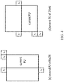
- FIG. 16 is an illustration of splitting a coding unit (CU) into two triangular prediction units.
- FIG. 17 shows an example of positions of neighboring blocks.
- FIG. 18 shows an example in which a CU applies the 1 st weighting factor group.
- FIG. 19 shows an example of motion vector storage implementation.
- FIG. 20 shows an example of a simplified affine motion model.
- FIG. 21 shows an example of affine MVF per sub-block.
- FIG. 22 shows examples of (a) 4-paramenter affine model (b) and 6-parameter affine model.
- FIG. 23 shows an example of a Motion Vector Predictor (MV) for AF_INTER mode.
- MV Motion Vector Predictor
- FIG. 24A-24B shows examples of candidates for AF_MERGE mode.
- FIG. 25 shows candidate positions for affine merge mode.
- FIG. 26 shows example process for bilateral matching.
- FIG. 27 shows example process of template matching.
- FIG. 28 illustrates an implementation of unilateral motion estimation (ME) in frame rate upconversion (FRUC).
- ME unilateral motion estimation
- FRUC frame rate upconversion
- FIG. 29 illustrates an embodiment of an Ultimate Motion Vector Expression (UMVE) search process.
- UMVE Ultimate Motion Vector Expression
- FIG. 30 shows examples of UMVE search points.
- FIG. 31 shows an example of distance index and distance offset mapping.
- FIG. 32 shows an example of an optical flow trajectory.
- FIG. 33A-33B show examples of Bi-directional Optical flow (BIO) w/o block extension: a) access positions outside of the block; b) padding used in order to avoid extra memory access and calculation.
- BIO Bi-directional Optical flow
- FIG. 34 illustrates an example of using Decoder-side motion vector refinement (DMVR) based on bilateral template matching.
- DMVR Decoder-side motion vector refinement
- FIG. 35 shows an example of neighboring samples used in a bilateral filter.
- FIG. 36 shows an example of windows covering two samples used in weight calculation.
- FIG. 37 shows an example of a decoding flow with the proposed history based motion vector prediction (HMVP) method.
- HMVP motion vector prediction
- FIG. 38 shows an example of updating the table in the proposed HMVP method.
- FIG. 39 is a block diagram of a hardware platform for implementing the video coding or decoding techniques described in the present document.
- FIG. 40 shows an example of a hardware platform for implementing methods and techniques described in the present document.
- FIG. 41 is a flowchart of an example method of video processing.
- FIG. 42 is a flowchart of an example method of video processing in accordance with the disclosure.
- This patent document is related to video coding technologies. Specifically, it is related to local illumination compensation (LIC) in video coding. It may be applied to the existing video coding standard like HEVC, or the standard (Versatile Video Coding) to be finalized. It may be also applicable to future video coding standards or video codec.
- LIC local illumination compensation
- Video coding standards have evolved primarily through the development of the well-known ITU-T and ISO/IEC standards.
- the ITU-T produced H.261 and H.263, ISO/IEC produced MPEG-1 and MPEG-4 Visual, and the two organizations jointly produced the H.262/MPEG-2 Video and H.264/MPEG-4 Advanced Video Coding (AVC) and H.265/HEVC standards.
- AVC H.264/MPEG-4 Advanced Video Coding
- H.265/HEVC H.265/HEVC
- the video coding standards are based on the hybrid video coding structure wherein temporal prediction plus transform coding are utilized.
- Joint Video Exploration Team JVET was founded by VCEG and MPEG jointly in 2015. Since then, many new methods have been adopted by JVET and put into the reference software named Joint Exploration Model (JEM).
- JEM Joint Exploration Model
- Each inter-predicted PU has motion parameters for one or two reference picture lists.
- Motion parameters include a motion vector and a reference picture index. Usage of one of the two reference picture lists may also be signalled using inter_pred_idc. Motion vectors may be explicitly coded as deltas relative to predictors.
- a merge mode is specified whereby the motion parameters for the current PU are obtained from neighboring PUs, including spatial and temporal candidates.
- the merge mode can be applied to any inter-predicted PU, not only for skip mode.
- the alternative to merge mode is the explicit transmission of motion parameters, where motion vector (to be more precise, motion vector difference compared to a motion vector predictor), corresponding reference picture index for each reference picture list and reference picture list usage are signalled explicitly per each PU.
- Such a mode is named Advanced motion vector prediction (AMVP) in this disclosure.
- the PU When signalling indicates that one of the two reference picture lists is to be used, the PU is produced from one block of samples. This is referred to as ‘uni-prediction’. Uni-prediction is available both for P-slices and B-slices.
- Bi-prediction When signalling indicates that both of the reference picture lists are to be used, the PU is produced from two blocks of samples. This is referred to as ‘bi-prediction’. Bi-prediction is available for B-slices only.
- steps are also schematically depicted in FIG. 1 .
- For spatial merge candidate derivation a maximum of four merge candidates are selected among candidates that are located in five different positions.
- temporal merge candidate derivation a maximum of one merge candidate is selected among two candidates. Since constant number of candidates for each PU is assumed at decoder, additional candidates are generated when the number of candidates obtained from step 1 does not reach the maximum number of merge candidate (MaxNumMergeCand) which is signalled in slice header. Since the number of candidates is constant, index of best merge candidate is encoded using truncated unary binarization (TU). If the size of CU is equal to 8, all the PUs of the current CU share a single merge candidate list, which is identical to the merge candidate list of the 2N ⁇ 2N prediction unit.
- TU truncated unary binarization
- a maximum of four merge candidates are selected among candidates located in the positions depicted in FIG. 2 .
- the order of derivation is A 1 , B 1 , B 0 , A 0 and B 2 .
- Position B 2 is considered only when any PU of position A 1 , B 1 , B 0 , A 0 is not available (e.g. because it belongs to another slice or tile) or is intra coded.
- candidate at position A 1 is added, the addition of the remaining candidates is subject to a redundancy check which ensures that candidates with same motion information are excluded from the list so that coding efficiency is improved.
- FIG. 3 shows examples of candidate pairs considered for redundancy check of spatial merge candidates.
- FIG. 5 is an Illustration of motion vector scaling for temporal merge candidate.
- the scaled motion vector for temporal merge candidate is obtained as illustrated by the dotted line in FIG.
- tb is defined to be the POC difference between the reference picture of the current picture and the current picture
- td is defined to be the POC difference between the reference picture of the co-located picture and the co-located picture.
- the reference picture index of temporal merge candidate is set equal to zero.
- the position for the temporal candidate is selected between candidates C 0 and C 1 , as depicted in FIG. 6 . If PU at position C 0 is not available, is intra coded, or is outside of the current CTU row, position C 1 is used. Otherwise, position C 0 is used in the derivation of the temporal merge candidate.
- Zero merge candidate Combined bi-predictive merge candidates are generated by utilizing spatial and temporal merge candidates. Combined bi-predictive merge candidate is used for B-Slice only. The combined bi-predictive candidates are generated by combining the first reference picture list motion parameters of an initial candidate with the second reference picture list motion parameters of another. If these two tuples provide different motion hypotheses, they will form a new bi-predictive candidate. As an example, FIG.
- Zero motion candidates are inserted to fill the remaining entries in the merge candidates list and therefore hit the MaxNumMergeCand capacity. These candidates have zero spatial displacement and a reference picture index which starts from zero and increases every time a new zero motion candidate is added to the list. The number of reference frames used by these candidates is one and two for uni and bi-directional prediction, respectively. Finally, no redundancy check is performed on these candidates.
- HEVC defines the motion estimation region (MER) whose size is signalled in the picture parameter set using the “log 2_parallel_merge_level_minus2” syntax element. When a MER is defined, merge candidates falling in the same region are marked as unavailable and therefore not considered in the list construction.
- AMVP exploits spatio-temporal correlation of motion vector with neighboring PUs, which is used for explicit transmission of motion parameters.
- a motion vector candidate list is constructed by firstly checking availability of left, above temporally neighboring PU positions, removing redundant candidates and adding zero vector to make the candidate list to be constant length. Then, the encoder can select the best predictor from the candidate list and transmit the corresponding index indicating the chosen candidate. Similarly with merge index signalling, the index of the best motion vector candidate is encoded using truncated unary. The maximum value to be encoded in this case is 2 (see FIG. 8 ). In the following sections, details about derivation process of motion vector prediction candidate are provided.
- motion vector candidate In motion vector prediction, two types of motion vector candidates are considered: spatial motion vector candidate and temporal motion vector candidate.
- spatial motion vector candidate derivation two motion vector candidates are eventually derived based on motion vectors of each PU located in five different positions as depicted in FIG. 8 .
- one motion vector candidate is selected from two candidates, which are derived based on two different co-located positions. After the first list of spatio-temporal candidates is made, duplicated motion vector candidates in the list are removed. If the number of potential candidates is larger than two, motion vector candidates whose reference picture index within the associated reference picture list is larger than 1 are removed from the list. If the number of spatio-temporal motion vector candidates is smaller than two, additional zero motion vector candidates is added to the list.
- a maximum of two candidates are considered among five potential candidates, which are derived from PUs located in positions as depicted in FIG. 2 , those positions being the same as those of motion merge.
- the order of derivation for the left side of the current PU is defined as A 0 , A 1 , and scaled A 0 , scaled A 1 .
- the order of derivation for the above side of the current PU is defined as B 0 , B 1 , B 2 , scaled B 0 , scaled B 1 , scaled B 2 .
- the no-spatial-scaling cases are checked first followed by the spatial scaling. Spatial scaling is considered when the POC is different between the reference picture of the neighboring PU and that of the current PU regardless of reference picture list. If all PUs of left candidates are not available or are intra coded, scaling for the above motion vector is allowed to help parallel derivation of left and above MV candidates. Otherwise, spatial scaling is not allowed for the above motion vector.
- the motion vector of the neighboring PU is scaled in a similar manner as for temporal scaling, as depicted as FIG. 9 .
- the main difference is that the reference picture list and index of current PU is given as input; the actual scaling process is the same as that of temporal scaling.
- each CU can have at most one set of motion parameters for each prediction direction.
- Two sub-CU level motion vector prediction methods are considered in the encoder by splitting a large CU into sub-CUs and deriving motion information for all the sub-CUs of the large CU.
- Alternative temporal motion vector prediction (ATMVP) method allows each CU to fetch multiple sets of motion information from multiple blocks smaller than the current CU in the collocated reference picture.
- STMVP spatial-temporal motion vector prediction
- the motion compression for the reference frames is currently disabled.
- the motion vectors temporal motion vector prediction is modified by fetching multiple sets of motion information (including motion vectors and reference indices) from blocks smaller than the current CU.
- the sub-CUs are square N ⁇ N blocks (N is set to 4 by default).
- ATMVP predicts the motion vectors of the sub-CUs within a CU in two steps.
- the first step is to identify the corresponding block in a reference picture with a so-called temporal vector.
- the reference picture is called the motion source picture.
- the second step is to split the current CU into sub-CUs and obtain the motion vectors as well as the reference indices of each sub-CU from the block corresponding to each sub-CU, as shown in FIG. 10 .
- a reference picture and the corresponding block is determined by the motion information of the spatial neighboring blocks of the current CU.
- the first merge candidate in the merge candidate list of the current CU is used.
- the first available motion vector as well as its associated reference index are set to be the temporal vector and the index to the motion source picture. This way, in ATMVP, the corresponding block may be more accurately identified, compared with TMVP, wherein the corresponding block (sometimes called collocated block) is always in a bottom-right or center position relative to the current CU.
- a corresponding block of the sub-CU is identified by the temporal vector in the motion source picture, by adding to the coordinate of the current CU the temporal vector.
- the motion information of its corresponding block (the smallest motion grid that covers the center sample) is used to derive the motion information for the sub-CU.
- the motion information of a corresponding N ⁇ N block is identified, it is converted to the motion vectors and reference indices of the current sub-CU, in the same way as TMVP of HEVC, wherein motion scaling and other procedures apply.
- the decoder checks whether the low-delay condition (i.e.
- motion vector MV x the motion vector corresponding to reference picture list X
- motion vector MV y the motion vector corresponding to reference picture list X
- FIG. 11 illustrates this concept. Let us consider an 8 ⁇ 8 CU which contains four 4 ⁇ 4 sub-CUs A, B, C, and D. The neighboring 4 ⁇ 4 blocks in the current frame are labelled as a, b, c, and d.
- the motion derivation for sub-CU A starts by identifying its two spatial neighbours.
- the first neighbour is the N ⁇ N block above sub-CU A (block c). If this block c is not available or is intra coded the other N ⁇ N blocks above sub-CU A are checked (from left to right, starting at block c).
- the second neighbour is a block to the left of the sub-CU A (block b). If block b is not available or is intra coded other blocks to the left of sub-CU A are checked (from top to bottom, staring at block b).
- the motion information obtained from the neighboring blocks for each list is scaled to the first reference frame for a given list.
- temporal motion vector predictor (TMVP) of sub-block A is derived by following the same procedure of TMVP derivation as specified in HEVC.
- the motion information of the collocated block at location D is fetched and scaled accordingly.
- all available motion vectors (up to 3) are averaged separately for each reference list. The averaged motion vector is assigned as the motion vector of the current sub-CU.
- the sub-CU modes are enabled as additional merge candidates and there is no additional syntax element required to signal the modes.
- Two additional merge candidates are added to merge candidates list of each CU to represent the ATMVP mode and STMVP mode. Up to seven merge candidates are used, if the sequence parameter set indicates that ATMVP and STMVP are enabled.
- the encoding logic of the additional merge candidates is the same as for the merge candidates in the HM, which means, for each CU in P or B slice, two more RD checks is needed for the two additional merge candidates.
- Pairwise average candidates are generated by averaging predefined pairs of candidates in the current merge candidate list, and the predefined pairs are defined as ⁇ (0, 1), (0, 2), (1, 2), (0, 3), (1, 3), (2, 3) ⁇ , where the numbers denote the merge indices to the merge candidate list.
- the averaged motion vectors are calculated separately for each reference list. If both motion vectors are available in one list, these two motion vectors are averaged even when they point to different reference pictures; if only one motion vector is available, use the one directly; if no motion vector is available, keep this list invalid.
- the pairwise average candidates replace the combined candidates in HEVC standard.
- JVET-K0135 planar motion vector prediction is proposed.
- FIG. 12 gives a brief description of the planar motion vector prediction process.
- Planar motion vector prediction is achieved by averaging a horizontal and vertical linear interpolation on 4 ⁇ 4 block basis as follows.
- P ( x,y ) ( H ⁇ P h ( x,y )+ W ⁇ P v ( x,y )+ H ⁇ W )/(2 ⁇ H ⁇ W ) Eq. (1)
- Wand H denote the width and the height of the block.
- (x,y) is the coordinates of current sub-block relative to the above left corner sub-block. All the distances are denoted by the pixel distances divided by 4.
- P(x, y) is the motion vector of current sub-block.
- L( ⁇ 1,y) and R(W,y) are the motion vectors of the 4 ⁇ 4 blocks to the left and right of the current block.
- A(x, ⁇ 1) and B(x,H) are the motion vectors of the 4 ⁇ 4 blocks to the above and bottom of the current block.
- the reference motion information of the left column and above row neighbour blocks are derived from the spatial neighbour blocks of current block.
- the reference motion information of the right column and bottom row neighbour blocks are derived as follows.
- AR is the motion vector of the above right spatial neighbour 4 ⁇ 4 block
- BR is the motion vector of the bottom right temporal neighbour 4 ⁇ 4 block
- BL is the motion vector of the bottom left spatial neighbour 4 ⁇ 4 block.
- the motion information obtained from the neighboring blocks for each list is scaled to the first reference picture for a given list.
- MVDs motion vector differences
- LAMVR locally adaptive motion vector resolution
- MVD can be coded in units of quarter luma samples, integer luma samples or four luma samples.
- the MVD resolution is controlled at the coding unit (CU) level, and MVD resolution flags are conditionally signalled for each CU that has at least one non-zero MVD components.
- a first flag is signalled to indicate whether quarter luma sample MV precision is used in the CU.
- the first flag (equal to 1) indicates that quarter luma sample MV precision is not used, another flag is signalled to indicate whether integer luma sample MV precision or four luma sample MV precision is used.
- the quarter luma sample MV resolution is used for the CU.
- the MVPs in the AMVP candidate list for the CU are rounded to the corresponding precision.
- CU-level RD checks are used to determine which MVD resolution is to be used for a CU. That is, the CU-level RD check is performed three times for each MVD resolution.
- the following encoding schemes are applied in the JEM.
- the encoding process is shown in FIG. 13 .
- 1 ⁇ 4 pel MV is tested and the RD cost is calculated and denoted as RDCost0, then integer MV is tested and the RD cost is denoted as RDCost1. If RDCost1 ⁇ th*RDCost0 (wherein th is a positive value), then 4-pel MV is tested; otherwise, 4-pel MV is skipped.
- RDCost1 ⁇ th*RDCost0 wherein th is a positive value
- 4-pel MV is tested; otherwise, 4-pel MV is skipped.
- motion information and RD cost etc. are already known for 1 ⁇ 4 pel MV when checking integer or 4-pel MV, which can be reused to speed up the encoding process of integer or 4-pel MV.
- motion vector accuracy is one-quarter pel (one-quarter luma sample and one-eighth chroma sample for 4:2:0 video).
- the accuracy for the internal motion vector storage and the merge candidate increases to 1/16 pel.
- the higher motion vector accuracy ( 1/16 pel) is used in motion compensation inter prediction for the CU coded with skip/merge mode.
- the integer-pel or quarter-pel motion is used, as described in section 2.2.2.
- SHVC upsampling interpolation filters which have same filter length and normalization factor as HEVC motion compensation interpolation filters, are used as motion compensation interpolation filters for the additional fractional pel positions.
- the chroma component motion vector accuracy is 1/32 sample in the JEM, the additional interpolation filters of 1/32 pel fractional positions are derived by using the average of the filters of the two neighboring 1/16 pel fractional positions.
- OBMC Overlapped Block Motion Compensation
- OBMC can be switched on and off using syntax at the CU level.
- the OBMC is performed for all motion compensation (MC) block boundaries except the right and bottom boundaries of a CU. Moreover, it is applied for both the luma and chroma components.
- a MC block is corresponding to a coding block.
- sub-CU mode includes sub-CU merge, affine and FRUC mode
- each sub-block of the CU is a MC block.
- OBMC is performed at sub-block level for all MC block boundaries, where sub-block size is set equal to 4 ⁇ 4, as illustrated in FIG. 14 .
- motion vectors of four connected neighboring sub-blocks are also used to derive prediction block for the current sub-block. These multiple prediction blocks based on multiple motion vectors are combined to generate the final prediction signal of the current sub-block.
- Prediction block based on motion vectors of a neighboring sub-block is denoted as P N , with N indicating an index for the neighboring above, below, left and right sub-blocks and prediction block based on motion vectors of the current sub-block is denoted as P C .
- P N is based on the motion information of a neighboring sub-block that contains the same motion information to the current sub-block
- the OBMC is not performed from P N . Otherwise, every sample of P N is added to the same sample in P C , i.e., four rows/columns of P N are added to P C .
- the weighting factors ⁇ 1 ⁇ 4, 1 ⁇ 8, 1/16, 1/32 ⁇ are used for P N and the weighting factors ⁇ 3 ⁇ 4, 7 ⁇ 8, 15/16, 31/32 ⁇ are used for P C .
- the exception are small MC blocks, (i.e., when height or width of the coding block is equal to 4 or a CU is coded with sub-CU mode), for which only two rows/columns of P N are added to P C .
- weighting factors ⁇ 1 ⁇ 4, 1 ⁇ 8 ⁇ are used for P N and weighting factors ⁇ 3 ⁇ 4, 7 ⁇ 8 ⁇ are used for P C .
- For P N generated based on motion vectors of vertically (horizontally) neighboring sub-block samples in the same row (column) of P N are added to P C with a same weighting factor.
- a CU level flag is signalled to indicate whether OBMC is applied or not for the current CU.
- OBMC is applied by default.
- the prediction signal formed by OBMC using motion information of the top neighboring block and the left neighboring block is used to compensate the top and left boundaries of the original signal of the current CU, and then the normal motion estimation process is applied.
- LIC Local Illumination Compensation
- CU inter-mode coded coding unit
- a least square error method is employed to derive the parameters a and b by using the neighboring samples of the current CU and their corresponding reference samples. More specifically, as illustrated in FIG. 15 , the subsampled (2:1 subsampling) neighboring samples of the CU and the corresponding samples (identified by motion information of the current CU or sub-CU) in the reference picture are used. The IC parameters are derived and applied for each prediction direction separately.
- the LIC flag is copied from neighboring blocks, in a way similar to motion information copy in merge mode; otherwise, an LIC flag is signalled for the CU to indicate whether LIC applies or not.
- LIC When LIC is enabled for a picture, additional CU level RD check is needed to determine whether LIC is applied or not for a CU.
- MR-SAD mean-removed sum of absolute difference
- MR-SATD mean-removed sum of absolute Hadamard-transformed difference
- LIC is disabled for the entire picture when there is no obvious illumination change between a current picture and its reference pictures.
- histograms of a current picture and every reference picture of the current picture are calculated at the encoder. If the histogram difference between the current picture and every reference picture of the current picture is smaller than a given threshold, LIC is disabled for the current picture; otherwise, LIC is enabled for the current picture.
- JVET-L0100 multi-hypothesis prediction is proposed, wherein hybrid intra and inter prediction is one way to generate multiple hypotheses.
- multi-hypothesis prediction When the multi-hypothesis prediction is applied to improve intra mode, multi-hypothesis prediction combines one intra prediction and one merge indexed prediction.
- a merge CU In a merge CU, one flag is signaled for merge mode to select an intra mode from an intra candidate list when the flag is true.
- the intra candidate list is derived from 4 intra prediction modes including DC, planar, horizontal, and vertical modes, and the size of the intra candidate list can be 3 or 4 depending on the block shape.
- horizontal mode is exclusive of the intra mode list and when the CU height is larger than the double of CU width, vertical mode is removed from the intra mode list.
- One intra prediction mode selected by the intra mode index and one merge indexed prediction selected by the merge index are combined using weighted average.
- DM is always applied without extra signaling.
- the weights for combining predictions are described as follow. When DC or planar mode is selected, or the CB width or height is smaller than 4, equal weights are applied. For those CBs with CB width and height larger than or equal to 4, when horizontal/vertical mode is selected, one CB is first vertically/horizontally split into four equal-area regions.
- (w_intra 1 , w_inter 1 ) is for the region closest to the reference samples and (w_intra 4 , w_inter 4 ) is for the region farthest away from the reference samples.
- the combined prediction can be calculated by summing up the two weighted predictions and right-shifting 3 bits.
- the intra prediction mode for the intra hypothesis of predictors can be saved for reference of the following neighboring CUs.
- the concept of the triangular prediction unit mode is to introduce a new triangular partition for motion compensated prediction. As shown in FIG. 16 , it splits a CU into two triangular prediction units (PUs), in either diagonal or inverse diagonal direction. Each triangular prediction unit in the CU is inter-predicted using its own uni-prediction motion vector and reference frame index which are derived from a uni-prediction candidate list. An adaptive weighting process is performed to the diagonal edge after predicting the triangular prediction units. Then, the transform and quantization process are applied to the whole CU. It is noted that this mode is only applied to skip and merge modes.
- the uni-prediction candidate list consists of five uni-prediction motion vector candidates. It is derived from seven neighboring blocks including five spatial neighboring blocks (1 to 5) and two temporal co-located blocks (6 to 7), as shown in FIG. 17 .
- the motion vectors of the seven neighboring blocks are collected and put into the uni-prediction candidate list according in the order of uni-prediction motion vectors, L0 motion vector of bi-prediction motion vectors, L1 motion vector of bi-prediction motion vectors, and averaged motion vector of the L0 and L1 motion vectors of bi-prediction motion vectors. If the number of candidates is less than five, zero motion vector is added to the list.
- One weighting factor group is selected based on the comparison of the motion vectors of two triangular prediction units.
- the 2 nd weighting factor group is used when the reference pictures of the two triangular prediction units are different from each other or their motion vector difference is larger than 16 pixels. Otherwise, the 1st weighting factor group is used. An example is shown in FIG. 18 .
- the motion vectors (Mv 1 and Mv 2 in FIG. 19 ) of the triangular prediction units are stored in 4 ⁇ 4 grids.
- either uni-prediction or bi-prediction motion vector is stored depending on the position of the 4 ⁇ 4 grid in the CU.
- uni-prediction motion vector either Mv 1 or Mv 2
- a bi-prediction motion vector is stored for the 4 ⁇ 4 grid located in the weighted area.
- the bi-prediction motion vector is derived from Mv 1 and Mv 2 according to the following rules:
- Mv 1 and Mv 2 have motion vector from different directions (L0 or L1)
- Mv 1 and Mv 2 are simply combined to form the bi-prediction motion vector.
- Mv 2 is scaled to the picture.
- Mv 1 and the scaled Mv 2 are combined to form the bi-prediction motion vector.
- Mv 1 is scaled to the picture.
- the scaled Mv 1 and Mv 2 are combined to form the bi-prediction motion vector.
- HEVC High Efficiency Video Coding
- MCP motion compensation prediction
- JEM JEM
- affine transform motion compensation prediction is applied. As shown in FIG. 20 , the affine motion field of the block is described by two control point motion vectors.
- the motion vector field (MVF) of a block is described by the following equation:
- sub-block based affine transform prediction is applied.
- the sub-block size M ⁇ N is derived as in Eq. (7), where MvPre is the motion vector fraction accuracy ( 1/16 in JEM), (v 2x , v 2y ) is motion vector of the bottom-left control point, calculated according to Eq. (6).
- M and N should be adjusted downward if necessary to make it a divisor of w and h, respectively.
- the motion vector of the center sample of each sub-block is calculated according to Equation 1, and rounded to 1/16 fraction accuracy. Then the motion compensation interpolation filters mentioned in section [00140] are applied to generate the prediction of each sub-block with derived motion vector.
- the high accuracy motion vector of each sub-block is rounded and saved as the same accuracy as the normal motion vector.
- affine motion modes there are two affine motion modes: AF_INTER mode and AF_MERGE mode.
- AF_INTER mode For CUs with both width and height larger than 8, AF_INTER mode can be applied.
- An affine flag in CU level is signalled in the bitstream to indicate whether AF_INTER mode is used.
- v 0 is selected from the motion vectors of the block A, B or C.
- the motion vector from the neighbour block is scaled according to the reference list and the relationship among the POC of the reference for the neighbour block, the POC of the reference for the current CU and the POC of the current CU. And the approach to select v 1 from the neighbour block D and E is similar. If the number of candidate list is smaller than 2, the list is padded by the motion vector pair composed by duplicating each of the AMVP candidates. When the candidate list is larger than 2, the candidates are firstly sorted according to the consistency of the neighboring motion vectors (similarity of the two motion vectors in a pair candidate) and only the first two candidates are kept. An RD cost check is used to determine which motion vector pair candidate is selected as the control point motion vector prediction (CPMVP) of the current CU.
- CPMVP control point motion vector prediction
- an index indicating the position of the CPMVP in the candidate list is signalled in the bitstream.
- mvd 1 and mvd 2 are predicted from mvd 0 .
- mv 0 mv 0 +mvd 0 Eq.
- mv 1 mv 1 +mvd 1 +mvd 0 Eq.
- mv 2 mv 2 +mvd 2 +mvd 0 Eq. (10)
- two motion vectors e.g., mvA(xA, yA) and mvB(xB, yB)
- newMV mvA+mvB and the two components of newMV is set to (xA+xB) and (yA+yB), respectively.
- MV of 2 or 3 control points needs to be determined jointly. Directly searching the multiple MVs jointly is computationally complex. A fast affine ME algorithm is proposed and is adopted into VTM/BMS.
- the fast affine ME algorithm is described for the 4-parameter affine model, and the idea can be extended to 6-parameter affine model.
- MVD of AF_INTER are derived iteratively.
- MV i (P) the MV derived in the ith iteration for position P
- dMV C i the delta updated for MV C in the ith iteration.
- MSE MSE
- Pic ref ′ ⁇ ( Q ) [ d ⁇ P ⁇ i ⁇ c r ⁇ e ⁇ f ⁇ ( Q ) d ⁇ x ⁇ ⁇ d ⁇ P ⁇ i ⁇ c r ⁇ e ⁇ f ⁇ ( Q ) d ⁇ y ] .
- a CU When a CU is applied in AF_MERGE mode, it gets the first block coded with affine mode from the valid neighbour reconstructed blocks. And the selection order for the candidate block is from left, above, above right, left bottom to above left as shown in FIG. 24A , the motion vectors v 2 , v 3 and v 4 of the top left corner, above right corner and left bottom corner of the CU which contains the block A are derived. And the motion vector v 0 of the top left corner on the current CU is calculated according to v 2 , v 3 and v 4 . Secondly, the motion vector v 1 of the above right of the current CU is calculated.
- the MVF of the current CU is generated.
- an affine flag is signalled in the bitstream when there is at least one neighbour block is coded in affine mode.
- FIGS. 24A and 24B show examples of candidates for AF_MERGE
- Inherited affine candidate means that the candidate is derived from the affine motion model of its valid neighbor affine coded block.
- the scan order for the candidate positions is: A1, B1, B0, A0 and B2.
- full pruning process is performed to check whether same candidate has been inserted into the list. If a same candidate exists, the derived candidate is discarded.
- Constructed affine candidate means the candidate is constructed by combining the neighbor motion information of each control point.
- the motion information for the control points is derived firstly from the specified spatial neighbors and temporal neighbor shown in FIG. 25 .
- T is temporal position for predicting CP4.
- the coordinates of CP1, CP2, CP3 and CP4 is (0, 0), (W, 0), (H, 0) and (W, H), respectively, where W and H are the width and height of current block.
- the checking priority is B2 ⁇ B3 ⁇ A2.
- B2 is used if it is available. Otherwise, if B2 is available, B3 is used. If both B2 and B3 are unavailable, A2 is used. If all the three candidates are unavailable, the motion information of CP1 cannot be obtained.
- the checking priority is B1 ⁇ B0.
- the checking priority is A1 ⁇ A0.
- Motion information of three control points are needed to construct a 6-parameter affine candidate.
- the three control points can be selected from one of the following four combinations ( ⁇ CP1, CP2, CP4 ⁇ , ⁇ CP1, CP2, CP3 ⁇ , ⁇ CP2, CP3, CP4 ⁇ , ⁇ CP1, CP3, CP4 ⁇ ).
- Combinations ⁇ CP1, CP2, CP3 ⁇ , ⁇ CP2, CP3, CP4 ⁇ , ⁇ CP1, CP3, CP4 ⁇ will be converted to a 6-parameter motion model represented by top-left, top-right and bottom-left control points.
- Motion information of two control points are needed to construct a 4-parameter affine candidate.
- the two control points can be selected from one of the following six combinations ( ⁇ CP1, CP4 ⁇ , ⁇ CP2, CP3 ⁇ , ⁇ CP1, CP2 ⁇ , ⁇ CP2, CP4 ⁇ , ⁇ CP1, CP3 ⁇ , ⁇ CP3, CP4 ⁇ ).
- Combinations ⁇ CP1, CP4 ⁇ , ⁇ CP2, CP3 ⁇ , ⁇ CP2, CP4 ⁇ , ⁇ CP1, CP3 ⁇ , ⁇ CP3, CP4 ⁇ will be converted to a 4-parameter motion model represented by top-left and top-right control points.
- reference index X (X being 0 or 1) of a combination
- the reference index with highest usage ratio in the control points is selected as the reference index of list X, and motion vectors point to difference reference picture will be scaled.
- full pruning process is performed to check whether same candidate has been inserted into the list. If a same candidate exists, the derived candidate is discarded.
- Pattern matched motion vector derivation (PMMVD) mode is a special merge mode based on Frame-Rate Up Conversion (FRUC) techniques. With this mode, motion information of a block is not signalled but derived at decoder side.
- PMMVD Pattern matched motion vector derivation
- FRUC Frame-Rate Up Conversion
- a FRUC flag is signalled for a CU when its merge flag is true.
- FRUC flag is false, a merge index is signalled and the regular merge mode is used.
- FRUC flag is true, an additional FRUC mode flag is signalled to indicate which method (bilateral matching or template matching) is to be used to derive motion information for the block.
- the decision on whether using FRUC merge mode for a CU is based on RD cost selection as done for normal merge candidate. That is the two matching modes (bilateral matching and template matching) are both checked for a CU by using RD cost selection. The one leading to the minimal cost is further compared to other CU modes. If a FRUC matching mode is the most efficient one, FRUC flag is set to true for the CU and the related matching mode is used.
- Motion derivation process in FRUC merge mode has two steps.
- a CU-level motion search is first performed, then followed by a Sub-CU level motion refinement.
- an initial motion vector is derived for the whole CU based on bilateral matching or template matching.
- a list of MV candidates is generated and the candidate which leads to the minimum matching cost is selected as the starting point for further CU level refinement.
- a local search based on bilateral matching or template matching around the starting point is performed and the MV results in the minimum matching cost is taken as the MV for the whole CU.
- the motion information is further refined at sub-CU level with the derived CU motion vectors as the starting points.
- the following derivation process is performed for a W ⁇ H CU motion information derivation.
- MV for the whole W ⁇ H CU is derived.
- the CU is further split into M ⁇ M sub-CUs.
- the value of M is calculated as in (16)
- D is a predefined splitting depth which is set to 3 by default in the JEM. Then the MV for each sub-CU is derived.
- the bilateral matching is used to derive motion information of the current CU by finding the closest match between two blocks along the motion trajectory of the current CU in two different reference pictures.
- the motion vectors MV 0 and MV 1 pointing to the two reference blocks shall be proportional to the temporal distances, i.e., TD 0 and TD 1 , between the current picture and the two reference pictures.
- the bilateral matching becomes mirror based bi-directional MV.
- template matching is used to derive motion information of the current CU by finding the closest match between a template (top and/or left neighboring blocks of the current CU) in the current picture and a block (same size to the template) in a reference picture. Except the aforementioned FRUC merge mode, the template matching is also applied to AMVP mode.
- AMVP has two candidates.
- template matching method a new candidate is derived. If the newly derived candidate by template matching is different to the first existing AMVP candidate, it is inserted at the very beginning of the AMVP candidate list and then the list size is set to two (meaning remove the second existing AMVP candidate).
- AMVP mode only CU level search is applied.
- the MV candidate set at CU level consists of:
- each valid MV of a merge candidate is used as an input to generate a MV pair with the assumption of bilateral matching.
- one valid MV of a merge candidate is (MVa, refa) at reference list A.
- the reference picture refb of its paired bilateral MV is found in the other reference list B so that refa and refb are temporally at different sides of the current picture. If such a refb is not available in reference list B, refb is determined as a reference which is different from refa and its temporal distance to the current picture is the minimal one in list B.
- MVb is derived by scaling MVa based on the temporal distance between the current picture and refa, refb.
- MVs from the interpolated MV field are also added to the CU level candidate list. More specifically, the interpolated MVs at the position (0, 0), (W/2, 0), (0, H/2) and (W/2, H/2) of the current CU are added.
- the original AMVP candidates are also added to CU level MV candidate set.
- the MV candidate set at sub-CU level consists of:
- the scaled MVs from reference pictures are derived as follows. All the reference pictures in both lists are traversed. The MVs at a collocated position of the sub-CU in a reference picture are scaled to the reference of the starting CU-level MV.
- ATMVP and STMVP candidates are limited to the four first ones.
- interpolated motion field is generated for the whole picture based on unilateral ME. Then the motion field may be used later as CU level or sub-CU level MV candidates.
- the motion field of each reference pictures in both reference lists is traversed at 4 ⁇ 4 block level.
- the motion of the reference block is scaled to the current picture according to the temporal distance TD 0 and TD 1 (the same way as that of MV scaling of TMVP in HEVC) and the scaled motion is assigned to the block in the current frame. If no scaled MV is assigned to a 4 ⁇ 4 block, the block's motion is marked as unavailable in the interpolated motion field.
- the matching cost is a bit different at different steps.
- the matching cost is the absolute sum difference (SAD) of bilateral matching or template matching.
- SAD absolute sum difference
- MV and MV s indicate the current MV and the starting MV, respectively.
- SAD is still used as the matching cost of template matching at sub-CU level search.
- MV is derived by using luma samples only. The derived motion will be used for both luma and chroma for MC inter prediction. After MV is decided, final MC is performed using 8-taps interpolation filter for luma and 4-taps interpolation filter for chroma.
- MV refinement is a pattern based MV search with the criterion of bilateral matching cost or template matching cost.
- two search patterns are supported—an unrestricted center-biased diamond search (UCBDS) and an adaptive cross search for MV refinement at the CU level and sub-CU level, respectively.
- UMBDS center-biased diamond search
- the MV is directly searched at quarter luma sample MV accuracy, and this is followed by one-eighth luma sample MV refinement.
- the search range of MV refinement for the CU and sub-CU step are set equal to 8 luma samples.
- the encoder can choose among uni-prediction from list0, uni-prediction from list1 or bi-prediction for a CU. The selection is based on a template matching cost as follows:
- cost0 is the SAD of list0 template matching
- cost1 is the SAD of list1 template matching
- costBi is the SAD of bi-prediction template matching.
- the value of factor is equal to 1.25, which means that the selection process is biased toward bi-prediction.
- the inter prediction direction selection is only applied to the CU-level template matching process.
- P TraditionalBiPred is the final predictor for the conventional bi-prediction
- P L0 and P L1 are predictors from L0 and L1, respectively
- RoundingOffset and shiftNum are used to normalize the final predictor.
- P GBi is the final predictor of GBi. (1 ⁇ w 1 ) and w 1 are the selected GBI weights applied to the predictors of L0 and L1, respectively. RoundingOffset GBi and shiftNum GBi are used to normalize the final predictor in GBi.
- the supported weights of w 1 is ⁇ 1 ⁇ 4, 3 ⁇ 8, 1 ⁇ 2, 5 ⁇ 8, 5/4 ⁇ .
- One equal-weight set and four unequal-weight sets are supported.
- the process to generate the final predictor is exactly the same as that in the conventional bi-prediction mode.
- the number of candidate weight sets is reduced to three.
- the weight selection in GBI is explicitly signaled at CU-level if this CU is coded by bi-prediction.
- the weight selection is inherited from the merge candidate.
- GBI supports DMVR to generate the weighted average of template as well as the final predictor for BMS-1.0.
- one or more additional prediction signals are signaled, in addition to the conventional uni/bi prediction signal.
- the resulting overall prediction signal is obtained by sample-wise weighted superposition.
- the resulting prediction signal p 3 (1 ⁇ ) p uni/bi + ⁇ h a Eq. (34)
- the weighting factor ⁇ is specified by the syntax element add_hyp_weight_idx, according to the following mapping:
- prediction list0/list1 is abolished, and instead one combined list is used.
- This combined list is generated by alternatingly inserting reference frames from list0 and list1 with increasing reference index, omitting reference frames which have already been inserted, such that double entries are avoided.
- more than one additional prediction signals can be used.
- the resulting overall prediction signal is accumulated iteratively with each additional prediction signal.
- the resulting overall prediction signal is obtained as the last p n (i.e., the p n having the largest index n).
- inter prediction blocks using MERGE mode (but not SKIP mode)
- additional inter prediction signals can be specified.
- MERGE not only the uni/bi prediction parameters, but also the additional prediction parameters of the selected merging candidate can be used for the current block.
- multi-hypothesis prediction When the multi-hypothesis prediction is applied to improve uni-prediction of AMVP mode, one flag is signaled to enable or disable multi-hypothesis prediction for inter_dir equal to 1 or 2, where 1, 2, and 3 represent list 0, list 1, and bi-prediction, respectively. Moreover, one more merge index is signaled when the flag is true. In this way, multi-hypothesis prediction turns uni-prediction into bi-prediction, where one motion is acquired using the original syntax elements in AMVP mode while the other is acquired using the merge scheme. The final prediction uses 1:1 weights to combine these two predictions as in bi-prediction.
- the merge candidate list is first derived from merge mode with sub-CU candidates (e.g., affine, alternative temporal motion vector prediction (ATMVP)) excluded.
- sub-CU candidates e.g., affine, alternative temporal motion vector prediction (ATMVP)
- each candidate of multi-hypothesis prediction implies a pair of merge candidates, containing one for the 1 st merge indexed prediction and the other for the 2 nd merge indexed prediction.
- the merge candidate for the 2 nd merge indexed prediction is implicitly derived as the succeeding merge candidate (i.e., the already signaled merge index plus one) without signaling any additional merge index. After removing redundancy by excluding those pairs, containing similar merge candidates and filling vacancy, the candidate list for multi-hypothesis prediction is formed.
- a merge or skip CU with multi-hypothesis prediction enabled can save the motion information of the additional hypotheses for reference of the following neighboring CUs in addition to the motion information of the existing hypotheses.
- sub-CU candidates e.g., affine, ATMVP
- multi-hypothesis prediction is not applied to skip mode.
- the worst-case bandwidth (required access samples per sample) for each merge or skip CU with multi-hypothesis prediction enabled is calculated in Table 1 and each number is less than half of the worst-case bandwidth for each 4 ⁇ 4 CU with multi-hypothesis prediction disabled.
- Ultimate motion vector expression (UMVE) is used for either skip or merge modes with a proposed motion vector expression method.
- UMVE re-uses merge candidate as same as using in VVC.
- a candidate can be selected, and is further expanded by the proposed motion vector expression method.
- UMVE provides a new motion vector expression with simplified signaling.
- the expression method includes starting point, motion magnitude, and motion direction.
- FIG. 29 shows an example of UMVE Search Process
- FIG. 30 shows examples of UMVE Search Points.
- This proposed technique uses a merge candidate list as it is. But only candidates which are default merge type (MRG_TYPE_DEFAULT_N) are considered for UMVE's expansion.
- Base candidate index defines the starting point.
- Base candidate index indicates the best candidate among candidates in Table 2 as follows.
- Base candidate IDX is not signaled.
- Distance index is motion magnitude information.
- Distance index indicates the pre-defined distance from the starting point information.
- Example pre-defined distance is shown in Table 3 as follows:
- Direction index represents the direction of the MVD relative to the starting point.
- the direction index can represent of the four directions as shown in Table 4 below.
- UMVE flag is singnaled right after sending a skip flag and merge flag. If skip and merge flag is true, UMVE flag is parsed. If UMVE flage is equal to 1, UMVE syntaxes are parsed. But, if not 1, AFFINE flag is parsed. If AFFINE flag is equal to 1, that is AFFINE mode, But, if not 1, skip/merge index is parsed for VTM's skip/merge mode.
- UMVE is extended to affine merge mode, also referred to as UMVE affine mode thereafter.
- the proposed method selects the first available affine merge candidate as a base predictor. Then it applies a motion vector offset to each control point's motion vector value from the base predictor. If there's no affine merge candidate available, this proposed method will not be used.
- the selected base predictor's inter prediction direction, and the reference index of each direction is used without change.
- the current block's affine model is assumed to be a 4-parameter model, only 2 control points need to be derived. Thus, only the first 2 control points of the base predictor will be used as control point predictors.
- a zero_MVD flag is used to indicate whether the control point of current block has the same MV value as the corresponding control point predictor. If zero_MVD flag is true, there's no other signaling needed for the control point. Otherwise, a distance index and an offset direction index is signaled for the control point.
- a distance offset table with size of 5 is used as shown in the table below.
- Distance index is signaled to indicate which distance offset to use.
- the mapping of distance index and distance offset values is shown in Table 5.
- FIG. 31 shows an example of distance index and distance offset mapping.
- the direction index can represent four directions as shown below, where only x or y direction may have an MV difference, but not in both directions.
- the signaled distance offset is applied on the offset direction for each control point predictor. Results will be the MV value of each control point.
- MV ( v x ,v y ) MVP ( v px ,v py )+ MV ( x - dir -factor*distance-offset, y - dir -factor*distance-offset) Eq. (36)
- the signaled distance offset is applied on the signaled offset direction for control point predictor's L0 motion vector; and the same distance offset with opposite direction is applied for control point predictor's L1 motion vector. Results will be the MV values of each control point, on each inter prediction direction.
- MV L0 ( v 0x ,v 0y ) MVP L0 ( v 0px ,v 0py )+ MV ( x - dir -factor*distance-offset, y - dir -factor*distance-offset) Eq.
- MV L1 ( v 0x ,v 0y ) MVP L1 ( v 0px ,v 0py )+ MV ( ⁇ x - dir -factor*distance-offset, ⁇ y - dir -factor*distance-offset) Eq. (38)
- Bi-directional Optical flow is sample-wise motion refinement which is performed on top of block-wise motion compensation for bi-prediction.
- the sample-level motion refinement doesn't use signalling.
- ⁇ I (k) / ⁇ x, ⁇ I (k) / ⁇ y are horizontal and vertical components of the I (k) gradient, respectively.
- ⁇ 0 and ⁇ 1 denote the distances to the reference frames as shown in FIG. 31 .
- the motion vector field (v x ,v y ) is determined by minimizing the difference ⁇ between values in points A and B (intersection of motion trajectory and reference frame planes on FIG. 32 ).
- the JEM uses a simplified approach making first a minimization in the vertical direction and then in the horizontal direction. This results in
- v x ( s 1 + r ) > m ? ⁇ clip ⁇ ⁇ 3 ⁇ ( - thBIO , thBIO , - s 3 ( s 1 + r ) ) : 0 Eq . ⁇ ( 43 )
- v y ( s 5 + r ) > m ? ⁇ clip ⁇ ⁇ 3 ⁇ ( - thBIO , thBIO , - s 6 - v x ⁇ s 2 / 2 ( s 5 + r ) ) : 0 Eq . ⁇ ( 44 )
- d bit depth of the video samples.
- I (k) , ⁇ I (k) / ⁇ x, ⁇ I (k) / ⁇ y are calculated only for positions inside the current block.
- (2M+1) ⁇ (2M+1) square window f centered in currently predicted point on a boundary of predicted block needs to accesses positions outside of the block (as shown in FIG. 33A ).
- values of I (k) , ⁇ I (k) / ⁇ x, ⁇ I (k) / ⁇ y outside of the block are set to be equal to the nearest available value inside the block. For example, this can be implemented as padding, as shown in FIG. 33B .
- BIO it's possible that the motion field can be refined for each sample.
- a block-based design of BIO is used in the JEM.
- the motion refinement is calculated based on 4 ⁇ 4 block.
- the values of s n in Equation 30 of all samples in a 4 ⁇ 4 block are aggregated, and then the aggregated values of s n in are used to derived BIO motion vectors offset for the 4 ⁇ 4 block. More specifically, the following formula is used for block-based BIO derivation:
- MV regiment of BIO might be unreliable due to noise or irregular motion. Therefore, in BIO, the magnitude of MV regiment is clipped to a threshold value thBIO.
- the threshold value is determined based on whether the reference pictures of the current picture are all from one direction. If all the reference pictures of the current picture are from one direction, the value of the threshold is set to 12 ⁇ 2 14-d ; otherwise, it is set to 12 ⁇ 2 13-d .
- Gradients for BIO are calculated at the same time with motion compensation interpolation using operations consistent with HEVC motion compensation process (2D separable FIR).
- the input for this 2D separable FIR is the same reference frame sample as for motion compensation process and fractional position (fracX, fracY) according to the fractional part of block motion vector.
- gradient filter BIOfilterG is applied in horizontal direction corresponding to the fractional position fracX with de-scaling shift by 18 ⁇ d.
- BIOfilterG corresponding to the fractional position fracY with de-scaling shift d ⁇ 8
- signal displacement is performed using BIOfilterS in horizontal direction corresponding to the fractional position fracX with de-scaling shift by 18 ⁇ d.
- the length of interpolation filter for gradients calculation BIOfilterG and signal displacement BIOfilterF is shorter (6-tap) in order to maintain reasonable complexity.
- Table 6 shows the filters used for gradients calculation for different fractional positions of block motion vector in BIO.
- Table 7 shows the interpolation filters used for prediction signal generation in BIO.
- BIO is applied to all bi-predicted blocks when the two predictions are from different reference pictures.
- BIO is disabled.
- BIO is not applied during the OBMC process. This means that BIO is only applied in the MC process for a block when using its own MV and is not applied in the MC process when the MV of a neighboring block is used during the OBMC process.
- bi-prediction operation for the prediction of one block region, two prediction blocks, formed using a motion vector (MV) of list0 and a MV of list1, respectively, are combined to form a single prediction signal.
- MV motion vector
- DMVR decoder-side motion vector refinement
- the two motion vectors of the bi-prediction are further refined by a bilateral template matching process.
- the bilateral template matching applied in the decoder to perform a distortion-based search between a bilateral template and the reconstruction samples in the reference pictures in order to obtain a refined MV without transmission of additional motion information.
- a bilateral template is generated as the weighted combination (i.e. average) of the two prediction blocks, from the initial MV 0 of list0 and MV 1 of list1, respectively, as shown in FIG. 34 .
- the template matching operation consists of calculating cost measures between the generated template and the sample region (around the initial prediction block) in the reference picture. For each of the two reference pictures, the MV that yields the minimum template cost is considered as the updated MV of that list to replace the original one.
- nine MV candidates are searched for each list. The nine MV candidates include the original MV and 8 surrounding MVs with one luma sample offset to the original MV in either the horizontal or vertical direction, or both.
- the two new MVs i.e., MV 0 ′ and MV 1 ′, as shown in FIG. 33 , are used for generating the final bi-prediction results.
- a sum of absolute differences (SAD) is used as the cost measure.
- SAD sum of absolute differences
- DMVR is applied for the merge mode of bi-prediction with one MV from a reference picture in the past and another from a reference picture in the future, without the transmission of additional syntax elements.
- JEM when LIC, affine motion, FRUC, or sub-CU merge candidate is enabled for a CU, DMVR is not applied.
- diffusion filter is proposed, wherein the intra/inter prediction signal of the CU may be further modified by diffusion filters.
- the Uniform Diffusion Filter is realized by convolving the prediction signal with a fixed mask that is either given as h I or as h IV , defined below. Besides the prediction signal itself, one line of reconstructed samples left and above of the block are used as an input for the filtered signal, where the use of these reconstructed samples can be avoided on inter blocks.
- pred be the prediction signal on a given block obtained by intra or motion compensated prediction.
- the prediction signal needs to be extended to a prediction signal pred ext .
- This extended prediction can be formed in two ways: Either, as an intermediate step, one line of reconstructed samples left and above the block are added to the prediction signal and then the resulting signal is mirrored in all directions. Or only the prediction signal itself is mirrored in all directions. The latter extension is used for inter blocks. In this case, only the prediction signal itself comprises the input for the extended prediction signal pred ext .
- the filter mask h I is given as:
- h IV h I *h I *h I *h I Eq. (50)
- directional filters instead of using signal adaptive diffusion filters, directional filters, a horizontal filter h hor and a vertical filter h ver , are used which still have a fixed mask. More precisely, the uniform diffusion filtering corresponding to the mask h I of the previous section is simply restricted to be either applied only along the vertical or along the horizontal direction.
- the vertical filter is realized by applying the fixed filter mask
- Bilateral filter is proposed in JVET-L0406, and it is always applied to luma blocks with non-zero transform coefficients and slice quantization parameter larger than 17. Therefore, there is no need to signal the usage of the bilateral filter.
- Bilateral filter if applied, is performed on decoded samples right after the inverse transform.
- the filter parameters i.e., weights are explicitly derived from the coded information.
- P 0,0 is the intensity of the current sample and P 0,0 ′ is the modified intensity of the current sample
- P k,0 and W k are the intensity and weighting parameter for the k-th neighboring sample, respectively.
- weight W k (x) associated with the k-th neighboring sample is defined as follows:
- ⁇ d is dependent on the coded mode and coding block sizes.
- the described filtering process is applied to intra-coded blocks, and inter-coded blocks when TU is further split, to enable parallel processing.
- weights function resulted from Eq. (52) are being adjusted by the ⁇ d parameter, shown in Table 8 as being dependent on coding mode and parameters of block partitioning (minimal size).
- P k,m and P 0,m represent the m-th sample value within the windows centered at P k,0 and P 0,0 , respectively.
- the window size is set to 3 ⁇ 3.
- An example of two windows covering P 2,0 and P 0,0 are depicted in FIG. 36 .
- the current (partially) decoded picture is considered as a reference picture.
- This current picture is put in the last position of reference picture list 0. Therefore, for a slice using the current picture as the only reference picture, its slice type is considered as a P slice.
- the bitstream syntax in this approach follows the same syntax structure for inter coding while the decoding process is unified with inter coding. The only outstanding difference is that the block vector (which is the motion vector pointing to the current picture) always uses integer-pel resolution.
- AMVR adaptive motion vector resolution
- the encoder performs RD check for blocks with either width or height no larger than 16.
- the block vector search is performed using hash-based search first. If there is no valid candidate found from hash search, block matching based local search will be performed.
- hash key matching 32-bit CRC
- hash key matching (32-bit CRC) between the current block and a reference block is extended to all allowed block sizes.
- the hash key calculation for every position in current picture is based on 4 ⁇ 4 blocks.
- a hash key matching to a reference block happens when all its 4 ⁇ 4 blocks match the hash keys in the corresponding reference locations. If multiple reference blocks are found to match the current block with the same hash key, the block vector costs of each candidates are calculated and the one with minimum cost is selected.
- the search range is set to be 64 pixels to the left and on top of current block.
- PCT Application No. PCT/CN2018/093987 titled “MOTION VECTOR PREDICTION BASED ON LOOK-UP TABLES,” filed on Jul. 2, 2018, the content of which is incorporated herein by reference, describes one or more look up tables with at least one motion candidate stored to predict motion information of a block.
- HMVP history-based MVP
- a HMVP candidate is defined as the motion information of a previously coded block.
- a table with multiple HMVP candidates is maintained during the encoding/decoding process. The table is emptied when a new slice is encountered. Whenever there is an inter-coded block, the associated motion information is added to the last entry of the table as a new HMVP candidate.
- the overall coding flow is depicted in FIG. 37 .
- a First-In-First-Out (FIFO) rule is applied so that the table always contains the latest previously coded L motion candidates.
- FIG. 38 depicts an example wherein the FIFO rule is applied to remove a HMVP candidate and add a new one to the table used in the proposed method.
- a redundancy checking process is applied firstly to identify whether there are identical or similar motion candidates in LUTs.
- WP applies a linear weight and a constant offset to each of the prediction signals depending on the (weight, offset) parameters associated with the ref_idx that is used to generate the prediction signal. Whereas there are some range constraints on these (weight, offset) values, the allowed ranges are relatively large and there is no normalization constraint on the parameter values. WP parameters are signaled at the picture level (in slice headers). WP has been shown to provide very large coding gain for fading sequences, and is generally expected to be enabled for such content.
- BWA uses a CU level index to indicate how to combine the two prediction signals in the case of bi-prediction.
- the BWA applies weighted averaging, i.e., the two weights add up to 1.
- BWA provides about 0.66% coding gain for the CTC RA configuration, but is much less effective than WP for the fading content (JVET-L0201).
- the PPS syntax element weight_bipred_flag is checked to determine if the gbi_idx is signaled at the current CU.
- the syntax signaling is modified as follows in bold text:
- the first alternative will disable BWA for all the reference pictures of the current slice, if the current slice refers to a PPS for which weighted_bipred_flag is set to 1.
- BWA is disabled only if both of the reference pictures used in the bi-prediction have turned on weighted prediction, i.e., the (weight, offset) parameters of these reference pictures have non-default values. This allows the bi-predicted CUs that use reference pictures with default WP parameters (i.e. WP is not invoked for these CUs) to still be able to use BWA.
- the syntax signaling is modified as follows in bold text:
- LIC two parameters including scaling parameter a and offset b need to be derived by using neighboring reconstructed pixels, which may cause latency issue.
- Hybrid intra and inter prediction, diffusion filter, bilateral filter, OBMC and LIC need to further modify the inter prediction signal in different ways, and they all have latency issue.
- LIC can only be performed for blocks located at CTU boundaries (called boundary blocks), and neighboring reconstructed samples out of the current CTU may be used for deriving LIC parameters. In this case, for those blocks that are not located CTU boundaries (called inner blocks), LIC is always disabled without being signaled.
- selection of neighboring reconstructed samples outside current CTU may depend on the position of the block relative to the CTU covering the current block.
- only left reconstructed neighboring samples of the CU may be used to derive the LIC parameters.
- only above reconstructed neighboring samples of the block may be used to derive the LIC parameters.
- left and/or above reconstructed neighboring samples of the block may be used to derive the LIC parameters.
- top-right and/or above reconstructed neighboring samples of the block are used to derive the LIC parameters.
- bottom-left and/or left reconstructed neighboring samples of the block are used to derive the LIC parameters.
- sets of LIC parameters can be derived for blocks located at CTU boundary only, and inner blocks of the CTU may inherit from one or multiple sets of these LIC parameter sets.
- a LIC parameter lookup table is maintained for each CTU, and each set of the derived LIC parameter is inserted into the LIC parameter table.
- such lookup table is maintained for each reference picture, and when deriving the LIC parameters, LIC parameters are derived for all reference pictures.
- such lookup table is emptied at the beginning of each CTU or CTU row or slice or tile or tile group or picture.
- the used set of LIC parameters is explicitly signaled. For example, an index is signaled to indicate which entry of the lookup table is used for each reference picture.
- the LIC flag shall be false.
- the LIC flag shall be false.
- the LIC flag can be true.
- One LIC parameter index is signaled for each reference picture with valid LIC parameters.
- each lookup table may correspond to one reference picture/one reference picture list/a certain range of block sizes/a certain coded mode/a certain block shape, etc. al.
- both LIC flag and LIC parameters are inherited from the corresponding neighboring block.
- the LIC flag is inherited and the LIC parameter may be signaled explicitly. In some embodiments, the LIC flag is signaled explicitly and the LIC parameter may be inherited. In some embodiments, both LIC flag and LIC parameter are signaled explicitly. In some embodiments, the differences between the LIP parameters of the block and the inherited parameters are signaled.
- LIC flag is true
- the used LIC parameter is derived implicitly using same methods as in [00148].
- both LIC flag and LIC parameter are inherited from the corresponding neighboring block.
- the LIC flag is inherited and the LIC parameters may be signaled explicitly. In some embodiments, the LIC flag is signaled explicitly and the LIC parameters may be inherited. In some embodiments, both LIC flag and LIC parameter are signaled explicitly.
- LIC if a block is coded with merge mode, for combined merge candidate or average merge candidate, LIC is always disabled.
- the LIC flag is set to true.
- the LIC flag is inherited and the LIC parameter may be signaled explicitly.
- the LIC flag is signaled explicitly and the LIC parameter may be inherited.
- both LIC flag and LIC parameter are signaled explicitly.
- LIC if a block is coded with merge mode from a HMVP merge candidate, LIC is always disabled. In some embodiments, if a block is coded with merge mode from a HMVP merge candidate, LIC is always enabled. In some embodiments, if LIC flag of the HMVP merge candidate is true, the LIC flag is set to be true. For example, LIC flag can be signaled explicitly. In some embodiments, if LIC flag of the HMVP merge candidate is true, the LIC flag is set to be true, and the LIP parameters are inherited from the HMVP merge candidate. In some embodiments, LIC parameters are signaled explicitly. In some embodiments, LIC parameters are derived implicitly.
- LIC may be used together with intra block copy (IBC, or current picture referencing) mode.
- IBC intra block copy
- indication of LIC usage may be further signaled.
- a LIC flag e.g., a LIC flag
- merge mode if an IBC coded block inherits motion information from a neighboring block, it may also inherit the LIC flag. In some embodiments, it may also inherit the LIC parameters.
- LIC parameter is derived implicitly using same method as in [00148]. In some embodiments, method described in Example 1 and/or Example 2 may be used. In some embodiments, if a block is coded with LIC enabled, indication of IBC usage may be further signaled.
- hybrid intra and inter prediction, diffusion filter, bilateral filter, OBMC, LIC or any other tools that modify the inter prediction signal or modify the reconstructed block from motion compensation (e.g., causing latency issues) are exclusively used.
- LIC if LIC is enabled, all other tools are disabled implicitly. If LIC flag is true (either explicitly signaled or implicitly derived), on/off flag of other tools (if there is any) are not signaled and implicitly derived to be off.
- hybrid intra and inter prediction if hybrid intra and inter prediction is enabled, all other tools are disabled implicitly. If hybrid intra and inter prediction flag is true (either explicitly signaled or implicitly derived), on/off flag of other tools (if there is any) are not signaled and implicitly derived to be off.
- diffusion filter if diffusion filter is enabled, all other tools are disabled implicitly. If diffusion filter flag is true (either explicitly signaled or implicitly derived), on/off flag of other tools (if there is any) are not signaled and implicitly derived to be off.
- OBMC if OBMC is enabled, all other tools are disabled implicitly. If OBMC flag is true (either explicitly signaled or implicitly derived), on/off flag of other tools (if there is any) are not signaled and implicitly derived to be off.
- bilateral filter if bilateral filter is enabled, all other tools are disabled implicitly. If bilateral filter flag is true (either explicitly signaled or implicitly derived), on/off flag of other tools (if there is any) are not signaled and implicitly derived to be off.
- different tools may be checked in order. Furthermore, such checking process terminates when one of the above tools is decided to be enabled.
- the checking order is LIC ⁇ diffusion filter ⁇ hybrid intra and inter prediction ⁇ OBMC ⁇ bilateral filter. In some embodiments, the checking order is LIC ⁇ diffusion filter ⁇ bilateral filter ⁇ hybrid intra and inter prediction ⁇ OBMC.
- the checking order is LIC ⁇ OBMC ⁇ diffusion filter ⁇ bilateral filter ⁇ hybrid intra and inter prediction. In some embodiments, the checking order is LIC ⁇ OBMC ⁇ diffusion filter ⁇ hybrid intra and inter prediction ⁇ bilateral filter. In some embodiments, the order may be adaptively changed based on previously coded information and/or based on coded information of current block (e.g., block size/reference picture/MV information/Low delay check flag/tile/picture/slice types), such as based on the modes of neighboring blocks.
- coded information of current block e.g., block size/reference picture/MV information/Low delay check flag/tile/picture/slice types
- LIC is used exclusively with GBI or multi-hypothesis inter prediction.
- GBI information may be signaled after LIC information. In some embodiments, whether to signal GBI information may depend on the signaled/inferred LIC information. Furthermore, whether to signal GBI information may depend on both LIC information and weighted prediction information associated with at least one reference picture of current block or of current tile/tile group/picture containing current block. In some embodiments, the information may be signaled in SPS/PPS/slice header/tile group header/tile/CTU/CU.
- LIC information may be signaled after GBI information. In some embodiments, whether to signal LIC information may depend on the signaled/inferred GBI information. Furthermore, whether to signal LIC information may depend on both GBI information and weighted prediction information associated with at least one reference picture of current block or of current tile/tile group/picture containing current block. In some embodiments, the information may be signaled in SPS/PPS/slice header/tile group header/tile/CTU/CU.
- LIC flag true, syntax elements required by GBI or multi-hypothesis inter prediction are not signaled.
- GBI flag true (e.g., unequal weights are applied to two or multiple reference pictures)
- syntax elements required by LIC or multi-hypothesis inter prediction are not signaled.
- LIC is used exclusively with sub-block technologies, such as affine mode. In some embodiments, LIC is used exclusively with triangular prediction mode. In some embodiments, when triangular prediction mode is enabled for one block, LIC is always disabled.
- the LIC flag of one TPM merge candidate may be inherited from a spatial or temporal block or other kinds of motion candidates (e.g., HMVP candidates). In some embodiments, the LIC flag of one TPM merge candidate may be inherited from some spatial or temporal blocks (e.g., only A1, B1). In some embodiments, LIC flag of one TPM merge candidate may be always set to false.
- syntax elements required by LIC or GBI are not signaled.
- different tools may be checked in a certain order. Furthermore, such checking process terminates when one of the above tools is decided to be enabled.
- the checking order is LIC ⁇ GBI ⁇ multi-hypothesis inter prediction. In some embodiments, the checking order is LIC ⁇ multi-hypothesis inter prediction ⁇ GBI. In some embodiments, the checking order is GBI ⁇ LIC ⁇ multi-hypothesis inter prediction.
- the checking order is GBI ⁇ multi-hypothesis inter prediction ⁇ LIC.
- the order may be adaptively changed based on previously coded information and/or based on coded information of current block (e.g., block size/reference picture/MV information/Low delay check flag/tile/picture/slice types), such as based on the modes of neighboring blocks.
- the above methods may be applied only when current block is uni-prediction.
- LIC is used exclusively with combined inter-intra prediction (CIIP).
- CIIP information may be signaled after LIC information. In some embodiments, whether to signal CIIP information may depend on the signaled/inferred LIC information. Furthermore, whether to signal CIIP information may depend on both LIC information and weighted prediction information associated with at least one reference picture of current block or of current tile/tile group/picture containing current block. In some embodiments, the information may be signaled in SPS/PPS/slice header/tile group header/tile/CTU/CU.
- LIC information may be signaled after CIIP information.
- whether to signal LIC information may depend on the signaled/inferred CIIP information. Furthermore, whether to signal LIC information may depend on both CIIP information and weighted prediction information associated with at least one reference picture of current block or of current tile/tile group/picture containing current block. In some embodiments, the information may be signaled in SPS/PPS/slice header/tile group header/tile/CTU/CU.
- syntax elements required by CIIP are not signaled. In some embodiments, if CIIP flag is true, syntax elements required by LIC are not signaled. In some embodiments, if CIIP is enabled, syntax elements required by LIC are not signaled.
- weighted prediction cannot be applied when one or some of the coding tools below is/are applied (exclusive with weighted prediction):
- BIO a.k.a. BDOF
- OBMC Overlapped block motion compensation
- the weighted prediction is enabled/disabled, then some of the coding tools are disabled/enabled accordingly. In some embodiments, due to some of the coding tools being enabled/disabled, the weighted prediction is disabled/enabled accordingly.
- the information e.g., a flag
- the flag can be inferred to be zero.
- the information may still be signaled expressively in SPS/PPS/slice header/tile group header/tile/CTU/CU.
- LIC may be used exclusively with weighted prediction at block level.
- the signalling of LIC information may depend on the weighted_bipred_flag.
- the signalling of LIC information may depend on the weighted_pred_flag.
- signaling of LIC information may depend on the weighted prediction parameters associated with one or all reference pictures associated with current block.
- LIC may be disabled for the block and LIC related syntax elements are not signaled.
- LIC may be still applied and weighted prediction may be disabled for the block.
- LIC may be applied on reference pictures where weighted prediction are not applied, and LIC may be disabled on reference pictures where weighted prediction are applied.
- LIC may be used with weighted prediction together for one block.
- LIC may be used exclusively with weighted prediction at picture level/slice level/tile group level/CTU group level.
- LIC is disabled and all related syntax element are not signaled.
- weighted prediction is disabled for all its reference pictures and all related syntax elements are not signaled.
- LIC may be used with weighted prediction together.
- LIC may be used exclusively with CPR mode. In some embodiments, when CPR mode is enabled for a block, signalling of indications of LIC usage and/or side information may be skipped. In some embodiments, when LIC mode is enabled for a block, signalling of indications of CPR usage and/or side information may be skipped.
- LIC may be used together with multi-hypothesis prediction (as described in [00304], [00314], [00316]).
- LIC flag is explicitly signaled for multi-hypothesis AMVP and merge mode (e.g., as described in [00314]).
- the explicitly signaled LIC flag is applied to both AMVP mode and merge mode.
- the explicitly signaled LIC flag is applied only to AMVP mode, while the LIC flag for the merge mode is inherited from the corresponding merge candidate.
- Different LIC flag may be used for AMVP mode and merge mode.
- different LIC parameters may be derived/inherited for AMVP mode and merge mode.
- LIC is always disabled for the merge mode.
- LIC flag is not signaled and LIC is always disabled for AMVP mode.
- LIC flag or/and LIC parameter may be inherited or derived.
- LIC flag is inherited from the corresponding merge candidates for multi-hypothesis merge mode (e.g., as described in [00316]). In some embodiments, LIC flag is inherited for each of the two selected merge candidates, therefore, different LIC flag may be inherited for the two selected merge candidates. Meanwhile, different LIC parameter may be derived/inherited for the two selected merge candidates. In some embodiments, LIC flag is only inherited for the 1 st selected merge candidate and LIC is always disabled for the 2 nd selected merge candidate.
- LIC flag is explicitly signaled for multi-hypothesis inter prediction mode (e.g., as described in [00304]).
- the explicitly signaled LIC flag may be applied to both merge mode (or UMVE mode) and the additional motion information.
- the explicitly signaled LIC flag may be applied to the additional motion information. While for merge mode, LIC flag or/and LIC parameter may be inherited or derived. In some embodiments, LIC is always disabled for the merge mode.
- LIC flag is not signaled and disabled for the additional motion information. While for merge mode, LIC flag or/and LIC parameter may be inherited or derived. In some embodiments, if the block is predicted with AMVP mode and additional motion information, the explicitly signaled LIC flag may be applied to both AMVP mode and the additional motion information. In some embodiments, LIC is always disabled for the additional motion information. In some embodiments, different LIC parameters may be derived/inherited for the merge mode (or UMVE mode)/AMVP mode and the additional motion information.
- illumination compensation may be applied to certain prediction signals, instead of all prediction signals.
- more than one flag may be signaled/derived to indicate the usage of illumination compensation for prediction signals.
- LIC flag may be inherited from the base merge candidate in UMVE mode.
- LIC parameters are derived implicitly as described in [00148].
- LIC parameters are derived implicitly as described in [00148].
- LIC parameters are inherited from base merge candidate.
- LIC flag may be signaled explicitly in UMVE mode.
- the above proposed methods or LIC may be applied under certain conditions, such as block sizes, slice/picture/tile types, or motion information.
- a block size contains smaller than M*H samples, e.g., 16 or 32 or 64 luma samples, proposed method or LIC are not allowed.
- X is set to 8.
- th1 and/or th2 is set to 8.
- th1 and/or th2 is set to 8.
- LIC is disabled for affine inter modes or/and affine merge mode.
- LIC is disabled for sub-block coding tools like ATMVP or/and STMVP or/and planar motion vector prediction modes.
- LIC is only applied to some components.
- LIC is applied to luma component.
- LIC is applied to chroma component.
- BIO or/and DMVR is disabled if LIC flag is true.
- LIC is disabled for bi-predicted block.
- LIC is disabled for inner block coded with AMVP mode.
- LIC is only allowed for uni-predicted block.
- selection of neighboring samples used for deriving LIC parameters may depend on coded information, block shape, etc. al.
- only one LIC flag may be signaled for a block with geometry portioning structure (such as triangular prediction mode).
- geometry portioning structure such as triangular prediction mode
- the LIC may be always disabled regardless the signaled LIC flag.
- LIC is always disabled for the bottom PU. In some embodiments, if the top PU is coded in merge mode, LIC flag is not signaled.
- LIC parameters are derived for each PU.
- above neighboring samples of the block are used for deriving LIC parameters of the top PU and left neighboring sample of the block are used for deriving LIC parameters of the left PU.
- one set of LIC parameters is derived and used for both PUs.
- LIC flag is not signaled and may be inherited from merge candidates.
- LIC parameters may be derived or inherited.
- the signaled LIC flag may be applied to PU coded in AMVP mode only.
- LIC flag or/and LIC parameters are inherited.
- LIC flag is not signaled and is disabled for the PU coded in AMVP mode.
- LIC flag or/and LIC parameters are inherited.
- LIC is disabled for the PU coded in merge mode.
- one LIC flag may be signaled for each PU.
- one PU may utilize reconstructed samples from another PU within current block which has been reconstructed to derive LIC parameters.
- LIC may be performed for partial pixels instead of the whole block.
- LIC may be only performed for pixels around block boundaries only, and for other pixels within the block, LIC is not performed.
- LIC is performed for the top W ⁇ N rows or N ⁇ H columns, wherein N is an integer number, W and H denote the width and the height of the block. For example, N is equal to 4.
- LIC is performed for the top-left (W ⁇ m) ⁇ (H ⁇ n) region, wherein m and n are integer numbers, W and H denote the width and the height of the block. For example, m and n are equal to 4.
- LIC flags may be utilized to update HMVP tables.
- an HMVP candidate may also include the LIC flag in addition to the motion vectors and other stuff.
- LIC flags are not utilized to update HMVP tables. For example, a default LIC flag value is set for each HMVP candidate.
- LIC coded blocks may also be utilized to update HMVP tables.
- motion candidates may be reordered according to LIC flags.
- candidates with LIC enabled may be put before all or partial of candidates with LIC disabled in the merge/AMVP or other motion candidate list.
- candidates with LIC disabled may be put before all or partial of candidates with LIC enabled in the merge/AMVP or other motion candidate list.
- the merge/AMVP or other motion candidate list construction process may be different.
- the merge/AMVP or other motion candidate list may not contain motion candidates derived from non-LIC-coded spatial/temporal neighboring or non-adjacent blocks or HMVP candidates with LIC flag equal to false.
- the merge/AMVP or other motion candidate list may not contain motion candidates derived from LIC-coded spatial/temporal neighboring or non-adjacent blocks or HMVP candidates with LIC flag equal to true.
- whether to enable or disable the above methods may be signaled in SPS/PPS/VPS/sequence header/picture header/slice header/tile group header/group of CTUs, etc. al.
- which method to be used may be signaled in SPS/PPS/VPS/sequence header/picture header/slice header/tile group header/group of CTUs, etc. al.
- whether to enable or disable the above methods and/or which method to be applied may be dependent on block dimension, video processing data unit (VPDU), picture type, low delay check flag, coded information of current block (such as reference pictures, uni or bi-prediction) or previously coded blocks.
- VPDU video processing data unit
- the PPS syntax element weight_bipred_flag is checked to determine if the LIC_enabled_flag is signaled at the current CU.
- the syntax signalling is modified shown as bold text below:
- the first alternative can disable LIC for all the reference pictures of the current slice/tile/tile group. For example,
- the current slice refers to a PPS for which weighted_pred_flag is set to 1 and current block is uni-predicted.
- LIC is disabled only if both of the reference pictures used in the bi-prediction have turned on weighted prediction, i.e., the (weight, offset) parameters of these reference pictures have non-default values. This allows the bi-predicted CUs that use reference pictures with default WP parameters (i.e. WP is not invoked for these CUs) to still be able to use LIC.
- LIC is disabled only if the reference picture used in the uni-prediction have turned on weighted prediction, i.e., the (weight, offset) parameters of these reference pictures have non-default values. This allows the uni-predicted CUs that use reference pictures with default WP parameters (i.e. WP is not invoked for these CUs) to still be able to use LIC.
- the syntax signalling is modified shown as bold text below:
- X indicates the reference picture list (X being 0 or 1).
- sps_LIC_enabled_flag which controls the usage of LIC per sequence may be replaced by indications of usage of LIC per picture/view/slice/tile/tile groups/CTU rows/regions/multiple CTUs/CTU.
- the control of signalling of LIC_enabled_flag may depend on block dimensions.
- the control of signalling of LIC_enabled_flag may depend on gbi index.
- the control of signalling of gbi index may further depend on LIC_enabled_flag.
- FIG. 39 is a block diagram illustrating an example of the architecture for a computer system or other control device 2600 that can be utilized to implement various portions of the presently disclosed technology.
- the computer system 2600 includes one or more processors 2605 and memory 2610 connected via an interconnect 2625 .
- the interconnect 2625 may represent any one or more separate physical buses, point to point connections, or both, connected by appropriate bridges, adapters, or controllers.
- the interconnect 2625 may include, for example, a system bus, a Peripheral Component Interconnect (PCI) bus, a HyperTransport or industry standard architecture (ISA) bus, a small computer system interface (SCSI) bus, a universal serial bus (USB), IIC (I2C) bus, or an Institute of Electrical and Electronics Engineers (IEEE) standard 674 bus, sometimes referred to as “Firewire.”
- PCI Peripheral Component Interconnect
- ISA HyperTransport or industry standard architecture
- SCSI small computer system interface
- USB universal serial bus
- I2C IIC
- IEEE Institute of Electrical and Electronics Engineers
- the processor(s) 2605 may include central processing units (CPUs) to control the overall operation of, for example, the host computer. In certain embodiments, the processor(s) 2605 accomplish this by executing software or firmware stored in memory 2610 .
- the processor(s) 2605 may be, or may include, one or more programmable general-purpose or special-purpose microprocessors, digital signal processors (DSPs), programmable controllers, application specific integrated circuits (ASICs), programmable logic devices (PLDs), or the like, or a combination of such devices.
- the memory 2610 can be or include the main memory of the computer system.
- the memory 2610 represents any suitable form of random access memory (RAM), read-only memory (ROM), flash memory, or the like, or a combination of such devices.
- RAM random access memory
- ROM read-only memory
- flash memory or the like, or a combination of such devices.
- the memory 2610 may contain, among other things, a set of machine instructions which, when executed by processor 2605 , causes the processor 2605 to perform operations to implement embodiments of the presently disclosed technology.
- the network adapter 2615 provides the computer system 2600 with the ability to communicate with remote devices, such as the storage clients, and/or other storage servers, and may be, for example, an Ethernet adapter or Fiber Channel adapter.
- FIG. 40 shows a block diagram of an example embodiment of a device 2700 that can be utilized to implement various portions of the presently disclosed technology.
- the mobile device 2700 can be a laptop, a smartphone, a tablet, a camcorder, or other types of devices that are capable of processing videos.
- the mobile device 2700 includes a processor or controller 2701 to process data, and memory 2702 in communication with the processor 2701 to store and/or buffer data.
- the processor 2701 can include a central processing unit (CPU) or a microcontroller unit (MCU).
- the processor 2701 can include a field-programmable gate-array (FPGA).
- FPGA field-programmable gate-array
- the mobile device 2700 includes or is in communication with a graphics processing unit (GPU), video processing unit (VPU) and/or wireless communications unit for various visual and/or communications data processing functions of the smartphone device.
- the memory 2702 can include and store processor-executable code, which when executed by the processor 2701 , configures the mobile device 2700 to perform various operations, e.g., such as receiving information, commands, and/or data, processing information and data, and transmitting or providing processed information/data to another device, such as an actuator or external display.
- the memory 2702 can store information and data, such as instructions, software, values, images, and other data processed or referenced by the processor 2701 .
- the mobile device 2700 includes an input/output (I/O) unit 2703 to interface the processor 2701 and/or memory 2702 to other modules, units or devices.
- I/O unit 2703 can interface the processor 2701 and memory 2702 with to utilize various types of wireless interfaces compatible with typical data communication standards, e.g., such as between the one or more computers in the cloud and the user device.
- the mobile device 2700 can interface with other devices using a wired connection via the I/O unit 2703 .
- the mobile device 2700 can also interface with other external interfaces, such as data storage, and/or visual or audio display devices 2704 , to retrieve and transfer data and information that can be processed by the processor, stored in the memory, or exhibited on an output unit of a display device 2704 or an external device.
- the display device 2704 can display a video frame modified based on the MVPs in accordance with the disclosed technology.
- FIG. 41 is a flowchart representation of a method 4100 of video processing.
- the method 4100 includes determining ( 4102 ), in a conversion between a video block and a bitstream representation of the video block, that a video block is a boundary block of a coding tree unit (CTU) in which the video block is positioned and therefore local illumination compensation (LIC) coding tool is enabled for the video block, deriving ( 4104 ), based on the determining that LIC coding tool is enabled for the video block, parameters for local illumination compensation (LIC) of the video block, and performing ( 4106 ) the conversion by adjusting pixel values of the video block using LIC.
- CTU coding tree unit
- LIC local illumination compensation
- FIG. 41 is a flowchart representation of a method 4100 of video processing.
- the method 4100 includes determining ( 4102 ), in a conversion between a video block and a bitstream representation of the video block, that a video block is a boundary block of a coding tree unit (C
- a video processing method comprising:
- a video block is a boundary block of a coding tree unit (CTU) in which the video block is positioned and therefore local illumination compensation (LIC) coding tool is enabled for the video block;
- CTU coding tree unit
- a video processing method comprising:
- a video block is an inner block of a coding tree unit (CTU) in which the video block is positioned and therefore local illumination compensation (LIC) coding tool is disabled for the video block;
- CTU coding tree unit
- LIC parameters for the video block based on one or more LIC parameters from the look-up table.
- bitstream representation is configured to include a flag indicating which LIC parameters are used for the current block.
- AMVP advanced motion vector prediction
- a video processing method comprising:
- LIC local illumination compensation
- a video processing method comprising:
- LIC local illumination compensation
- a video processing method comprising:
- LIC local illumination compensation
- a video processing method comprising:
- LIC local illumination compensation
- a video processing method comprising:
- LIC local illumination compensation
- LIC local illumination compensation
- GBi generalized bi-prediction
- multi-hypothesis inter prediction coding tools are enabled for use by the current block
- a method for video processing comprising:
- LIC local illumination compensation
- CIIP combined inter-intra prediction
- bit field is includes at a sequence level, a picture level, a video level, a sequence header level, a picture header level, a slice header level, a tile level or a group of coding tree unit level.
- a video encoding apparatus comprising a processor configured to implement a method recited in any one or more of clauses 1 to 72.
- a video decoding apparatus comprising a processor configured to implement a method recited in any one or more of clauses 1 to 72.
- FIG. 42 is a flowchart representation of a method 4200 of video processing.
- the method 4200 includes generating ( 4210 ), for a conversion between a current block of a video and a bitstream representation of the video, a motion vector for the current block.
- the method 4200 includes invoking ( 4220 ) a weighted prediction processing tool or a second processing tool in a mutually exclusive manner.
- invoking the second processing tool comprises refining the motion vector.
- the method 4200 also includes performing ( 4230 ) the conversion according to the invoking.
- the conversion generates the current block from the bitstream representation. In some embodiments, wherein the conversion generates the bitstream representation from the current block.
- invoking the weighted prediction processing tool comprises applying a linear weight and an offset to derive a final prediction.
- the invoking comprises determining, in case the weighted prediction processing tool is disabled for the current block, that the second processing tool is enabled for the current block. In some embodiments, the invoking comprises determining, in case the weighted prediction processing tool is enabled for the current block, that the second processing tool is disabled for the current block. In some embodiments, the invoking comprises determining, in case the second processing tool is disabled for the current block, that weighted prediction processing tool is enabled for the current block. In some embodiments, the invoking comprises determining, in case the second processing tool is enabled for the current block, that weighted prediction processing tool is disabled for the current block.
- refining the motion vector comprises applying a motion vector offset to refine the motion vector.
- the motion vector offset is determined based on a sum of absolute differences derived from different reference lists of the current block. In some embodiments, the sum of absolute differences is calculated based on partial positions derived from different reference lists of the current block.
- the second processing tool comprises a decoder side motion vector refinement (DMVR) process.
- DMVR decoder side motion vector refinement
- the invoking further comprises invoking the weighted prediction processing tool or a third processing tool in a mutually exclusive manner.
- the third processing tool applies a prediction offset to refine the final prediction.
- the prediction offset is determined based on at least one of a horizontal or a vertical gradient derived from different reference lists of the current block.
- the third processing tool comprises a bi-directional optical flow prediction (BDOF) process.
- BDOF bi-directional optical flow prediction
- the invoking further comprises invoking a weighted prediction processing tool or a fourth processing tool in a mutually exclusive manner.
- the fourth processing tool comprises one of: a combined inter-intra prediction (CIIP) processing tool that generates the final prediction based on an inter prediction and an intra prediction, an affine processing tool that generates the final prediction based on a control point motion vector, or an overlapped block motion compensation (OBMC) processing tool that generates the final prediction based on motion vectors of a sub-block and spatial neighboring sub-block.
- CIIP inter-intra prediction
- OBMC overlapped block motion compensation
- information indicating whether the second processing tool is applied is defaulted to have a value of zero.
- information indicating whether the second processing tool is applied is signaled in a sequence parameter set (SPS), a picture parameter set (PPS), a slice header, a tile group header, a tile, a coding unit (CU), or a coding tree unit (CTU).
- SPS sequence parameter set
- PPS picture parameter set
- CTU coding tree unit
- the disclosed and other embodiments, modules and the functional operations described in this document can be implemented in digital electronic circuitry, or in computer software, firmware, or hardware, including the structures disclosed in this document and their structural equivalents, or in combinations of one or more of them.
- the disclosed and other embodiments can be implemented as one or more computer program products, i.e., one or more modules of computer program instructions encoded on a computer readable medium for execution by, or to control the operation of, data processing apparatus.
- the computer readable medium can be a machine-readable storage device, a machine-readable storage substrate, a memory device, a composition of matter effecting a machine-readable propagated signal, or a combination of one or more them.
- data processing apparatus encompasses all apparatus, devices, and machines for processing data, including by way of example a programmable processor, a computer, or multiple processors or computers.
- the apparatus can include, in addition to hardware, code that creates an execution environment for the computer program in question, e.g., code that constitutes processor firmware, a protocol stack, a database management system, an operating system, or a combination of one or more of them.
- a propagated signal is an artificially generated signal, e.g., a machine-generated electrical, optical, or electromagnetic signal, that is generated to encode information for transmission to suitable receiver apparatus.
- a computer program (also known as a program, software, software application, script, or code) can be written in any form of programming language, including compiled or interpreted languages, and it can be deployed in any form, including as a stand-alone program or as a module, component, subroutine, or other unit suitable for use in a computing environment.
- a computer program does not necessarily correspond to a file in a file system.
- a program can be stored in a portion of a file that holds other programs or data (e.g., one or more scripts stored in a markup language document), in a single file dedicated to the program in question, or in multiple coordinated files (e.g., files that store one or more modules, sub programs, or portions of code).
- a computer program can be deployed to be executed on one computer or on multiple computers that are located at one site or distributed across multiple sites and interconnected by a communication network.
- the processes and logic flows described in this document can be performed by one or more programmable processors executing one or more computer programs to perform functions by operating on input data and generating output.
- the processes and logic flows can also be performed by, and apparatus can also be implemented as, special purpose logic circuitry, e.g., an FPGA (field programmable gate array) or an ASIC (application specific integrated circuit).
- processors suitable for the execution of a computer program include, by way of example, both general and special purpose microprocessors, and any one or more processors of any kind of digital computer.
- a processor will receive instructions and data from a read only memory or a random-access memory or both.
- the essential elements of a computer are a processor for performing instructions and one or more memory devices for storing instructions and data.
- a computer will also include, or be operatively coupled to receive data from or transfer data to, or both, one or more mass storage devices for storing data, e.g., magnetic, magneto optical disks, or optical disks.
- mass storage devices for storing data, e.g., magnetic, magneto optical disks, or optical disks.
- a computer need not have such devices.
- Computer readable media suitable for storing computer program instructions and data include all forms of non-volatile memory, media and memory devices, including by way of example semiconductor memory devices, e.g., EPROM, EEPROM, and flash memory devices; magnetic disks, e.g., internal hard disks or removable disks; magneto optical disks; and CD ROM and DVD-ROM disks.
- semiconductor memory devices e.g., EPROM, EEPROM, and flash memory devices
- magnetic disks e.g., internal hard disks or removable disks
- magneto optical disks e.g., CD ROM and DVD-ROM disks.
- the processor and the memory can be supplemented by, or incorporated in, special purpose logic circuitry.
Abstract
Description
-
- Step 1: Initial candidates derivation
- Step 1.1: Spatial candidates derivation
- Step 1.2: Redundancy check for spatial candidates
- Step 1.3: Temporal candidates derivation
- Step 2: Additional candidates insertion
- Step 2.1: Creation of bi-predictive candidates
- Step 2.2: Insertion of zero motion candidates
- Step 1: Initial candidates derivation
-
- No spatial scaling
- (1) Same reference picture list, and same reference picture index (same POC)
- (2) Different reference picture list, but same reference picture (same POC)
- Spatial scaling
- (3) Same reference picture list, but different reference picture (different POC)
- (4) Different reference picture list, and different reference picture (different POC)
- No spatial scaling
| TABLE 1 |
| Operation analysis for the pairwise average candidates |
| Max | Max | Max | Max | Max | |||||
| number of | number of | number | number of | Additional | number of | ||||
| Merge | potential | candidate | of MV | temporal | local | memory | |||
| list size | candidates | comparisons | scalings | candidates | | access | Others | ||
| 6, 8, 10 | 6 | 0 | 0 | 0 | 0 | 0 | Replace HEVC | ||
| combined | |||||||||
| candidates, | |||||||||
| need additional | |||||||||
| calculations | |||||||||
| for averaging | |||||||||
P(x,y)=(H×P h(x,y)+W×P v(x,y)+H×W)/(2×H×W) Eq. (1)
P h(x,y)=(W−1−x)×L(−1,y)+(x+1)×R(W,y) Eq. (2)
P v(x,y)=(H−1−y)×A(x,−1)+(y+1)×B(x,H) Eq. (3)
R(W,y)=((H−y−1)×AR+(y+1)×BR)/H Eq. (4)
B(x,H)=((W−x−1)×BL+(x+1)×BR)/W Eq. (5)
-
- During RD check of a CU with normal quarter luma sample MVD resolution, the motion information of the current CU (integer luma sample accuracy) is stored. The stored motion information (after rounding) is used as the starting point for further small range motion vector refinement during the RD check for the same CU with integer luma sample and 4 luma sample MVD resolution so that the time-consuming motion estimation process is not duplicated three times.
- RD check of a CU with 4 luma sample MVD resolution is conditionally invoked. For a CU, when RD cost integer luma sample MVD resolution is much larger than that of quarter luma sample MVD resolution, the RD check of 4 luma sample MVD resolution for the CU is skipped.
-
- 1st weighting factor group: {⅞, 6/8, 4/8, 2/8, ⅛} and {⅞, 4/8, ⅛} are used for the luminance and the chrominance samples, respectively;
- 2nd weighting factor group: {⅞, 6/8, ⅝, 4/8, ⅜, 2/8, ⅛} and { 6/8, 4/8, 2/8} are used for the luminance and the chrominance samples, respectively.
mv 0 =
mv 1 =
mv 2 =
MV(p)=A(P)*MV C T Eq. (15)
dMV (0,0) h =dMV C i[0] Eq. (22)
dMV (0,w) h =dMV C i[1]*w+dMV C i[2] Eq. (23)
dMV (0,0) v =dMV C i[2] Eq. (24)
dMV (0,w) v =−dMV C i[3]*w+dMV C i[2] Eq. (25)
fdMV (0,0) h=Σi=0 n−1 dMV C i[0] Eq. (26)
fdMV (0,w) h=Σi=0 n−1 dMV C i[1]*w+Σ i=0 n−1 dMV C i[0] Eq. (27)
fdMV (0,0) v=Σi=0 n−1 dMV C i[2] Eq. (28)
fdMV (0,w) v=Σi=0 n−1 −dMV C i[3]*w+Σ i=0 n−1 dMV C i[2] Eq. (29)
C=SAD+w·(|MV x −MV x s |+|WV y −MV y s|) Eq. (31)
| If costBi <= factor * min (cost0, cost1) | |
| bi-prediction is used; | |
| Otherwise, if cost0 <= cost1 | |
| uni-prediction from list0 is used; | |
| Otherwise, | |
| uni-prediction from list1 is used; | |
P TraditionalBiPred=(P L0 +P L1+RoundingOffset)>>ShiftNum Eq. (32)
P GBi=((1−w 1)×P L0 +w 1 ×P L1+RoundingOffsetGBi)>>ShiftNumGBi Eq. (33)
p 3=(1−α)p uni/bi +αh a Eq. (34)
| prediction_unit( x0, y0, nPbW, nPbH ) { | Descriptor |
| ... | |
| if( ! cu_skip_flag[ x0 ][ y0 ]) { | |
| i = 0 | |
| readMore = 1 | |
| while( i < MaxNumAdditionalHypotheses && | |
| readMore ) { | |
| additional_hypothesis_flag[ x0 ][ y0 ][ i ] | ae(v) |
| if( additional_hypothesis_flag[ x0 ][ y0][ i ] ) { | |
| ref_idx_add_hyp[ x0 ][ y0 ][ i ] | ae(v) |
| mvd_coding( x0, y0, 2+i ) | |
| mvp_add_hyp_flag[ x0 ][ y0 ][ i ] | ae(v) |
| add_hyp_weight_idx[ x0 ][ y0 ][ i ] | ae(v) |
| } | |
| readMore = additional_hypothesis_flag[ x0 ][ y0 ][ i ] | |
| i++ | |
| } | |
| } | |
| } | |
| | α | ||
| 0 | 1/4 | ||
| 1 | −1/8 | ||
p n+1=(1−αn+1)p n+αn+1 h n+1 Eq. (35)
| TABLE 2 |
| Example Base Candidate IDX |
| | ||||||
| IDX | ||||||
| 0 | 1 | 2 | 3 | |||
| Nth MVP | 1st |
2nd |
3rd |
4th MVP | ||
| TABLE 3 |
| Example Distance |
| Distance IDX |
| 0 | 1 | 2 | 3 | 4 | 5 | 6 | 7 | |
| |
1/4- |
1/2-pel | 1-pel | 2-pel | 4-pel | 8-pel | 16- | 32- |
| distance | pel | pel | ||||||
| TABLE 4 |
| Example Direction IDX |
| Direction IDX | 00 | 01 | 10 | 11 |
| x-axis | + | − | N/A | N/A |
| y-axis | N/A | N/A | + | − |
| TABLE 5 |
| Example Distance Offset |
| |
0 | 1 | 2 | 3 | 4 | ||
| Distance-offset | 1/2-pel | 1-pel | 2-pel | 4-pel | 8-pel | ||
| Offset Direction IDX | 00 | 01 | 10 | 11 |
| x-dir-factor | +1 | −1 | 0 | 0 |
| y-dir- |
0 | 0 | +1 | −1 |
MV(v x ,v y)=MVP(v px ,v py)+MV(x-dir-factor*distance-offset,y-dir-factor*distance-offset) Eq. (36)
MV L0(v 0x ,v 0y)=MVP L0(v 0px ,v 0py)+MV(x-dir-factor*distance-offset,y-dir-factor*distance-offset) Eq. (37)
MV L1(v 0x ,v 0y)=MVP L1(v 0px ,v 0py)+MV(−x-dir-factor*distance-offset,−y-dir-factor*distance-offset) Eq. (38)
∂I (k) /∂t+v x ∂I (k) /∂x+v y ∂I (k) /∂y=0. Eq. (39)
Δ=(I (0) −I (1) 0 +v x(τ1 ∂I (1) /∂x+τ 0 ∂I (0) /∂x)+v y(τ1 ∂I (1) /∂y+τ 0 ∂I (0) /∂y)) Eq. (41)
r=500·4d-8 Eq. (46)
m=700·4d-8 Eq. (47)
| TABLE 6 |
| Example filters for gradients calculation in BIO |
| Fractional | Interpolation filter for gradient | ||
| pel position | (BIOfilterG) | ||
| 0 | { 8, −39, −3, 46, −17, 5} | ||
| 1/16 | { 8, −32, −13, 50, −18, 5} | ||
| 1/8 | { 7, −27, −20, 54, −19, 5} | ||
| 3/16 | { 6, −21, −29, 57, −18, 5} | ||
| 1/4 | { 4, −17, −36, 60, −15, 4} | ||
| 5/16 | { 3, −9, −44, 61, −15, 4} | ||
| 3/8 | { 1, −4, −48, 61, −13, 3} | ||
| 7/16 | { 0, 1, −54, 60, −9, 2} | ||
| 1/2 | { −1, 4, −57, 57, −4, 1} | ||
| TABLE 7 |
| Example interpolation filters for prediction signal generation in BIO |
| Fractional | Interpolation filter for prediction signal |
| pel position | (BIOfilterS) |
| 0 | { 0, 0, 64, 0, 0, 0} |
| 1/16 | { 1, −3, 64, 4, −2, 0} |
| 1/8 | { 1, −6, 62, 9, −3, 1} |
| 3/16 | { 2, −8, 60, 14, −5, 1} |
| 1/4 | { 2, −9, 57, 19, −7, 2} |
| 5/16 | { 3, −10, 53, 24, −8, 2} |
| 3/8 | { 3, −11, 50, 29, −9, 2} |
| 7/16 | { 3, −11, 44, 35, −10, 3} |
| 1/2 | { 3, −10, 35, 44, −11, 3} |
h IV =h I *h I *h I *h I Eq. (50)
to the prediction signal and the horizontal filter is realized by using the transposed mask hhor=hver t.
P 0,0 ′=P 0,0+Σk=1 K W k(abs(P k,0 −P 0,0))×(P k,0 −P 0,0), Eq. (51)
| TABLE 8 |
| Example value of σd for different block sizes and coding modes |
| Min (block width, block height) | Intra | Inter mode | ||
| 4 | 82 | 62 | ||
| 8 | 72 | 52 | ||
| Other | 52 | 32 | ||
| pic_parameter_set_rbsp( ) { | Descriptor | ||
| pps_pic_parameter_set_id | ue(v) | ||
| pps_seq_parameter_set_id | ue(v) | ||
| init_qp_minus26 | se(v) | ||
| transform_skip_enabled_flag | u(1) | ||
| cu_qp_delta_enabled_flag | u(1) | ||
| if( cu_qp_delta_enabled_flag ) | |||
| diff_cu_qp_delta_depth | ue(v) | ||
| pps_cb_qp_offset | se(v) | ||
| pps_cr_qp_offset | se(v) | ||
| pps_slice_chroma_qp_offsets_present_flag | u(1) | ||
| weighted_pred_flag | u(1) | ||
| weighted_bipred_flag | u(1) | ||
| deblocking_filter_control_present_flag | u(1) | ||
| if( deblocking_filter_control_present_flag ) { | |||
| deblocking_filter_override_enabled_flag | u(1) | ||
| pps_deblocking_filter_disabled_flag | u(1) | ||
| if( !pps_deblocking_filter_disabled_flag ) { | |||
| pps_beta_offset_div2 | se(v) | ||
| pps_tc_offset_div2 | se(v) | ||
| } | |||
| } | |||
| rbsp_trailing_bits( ) | |||
| } | |||
| slice_header( ) { | Descriptor |
| slice_pic_parameter_set_id | ue(v) |
| slice_address | u(v) |
| slice_type | ue(v) |
| if( partition_constraints_override_enabled_flag ) { | |
| partition_constraints_override_flag | ue(v) |
| if( partition_constraints_override_flag ) { | |
| slice_log2_diff_min_qt_min_cb_luma | ue(v) |
| slice_max_mtt_hierarchy_depth_luma | ue(v) |
| if( slice_max_mtt_hierarchy_depth_luma != 0 ) | |
| slice_log2_diff_max_bt_min_qt_luma | ue(v) |
| slice_log2_diff_max_tt_min_qt_luma | ue(v) |
| } | |
| if( slice_type = = I && qtbtt_dual_tree_intra_flag ) { | |
| slice_log2_diff_min_qt_min_cb_chroma | ue(v) |
| slice_max_mtt_hierarchy_depth_chroma | ue(v) |
| if( slice_max_mtt_hierarchy_depth_chroma != 0 ) | |
| slice_log2_diff_max_bt_min_qt_chroma | ue(v) |
| slice_log2_diff_max_tt_min_qt_chroma | ue(v) |
| } | |
| } | |
| } | |
| } | |
| if ( slice_type != I) { | |
| if( sps_temporal_mvp_enabled_flag ) | |
| slice_temporal_mvp_enabled_flag | u(1) |
| if( slice_type = = B) | |
| mvd_I1_zero_flag | u(1) |
| if( slice_temporal_mvp_enabled_flag ) { | |
| if( slice_type = = B ) | |
| collocated_from_I0_flag | u(1) |
| } | |
| if( ( weighted_pred_flag && slice_type = = P ) || | |
| ( weighted_bipred_flag && slice_type = = B )) | |
| pred_weight_table( ) | |
| six_minus_max_num_merge_cand | ue(v) |
| if( sps_affine_enable_flag ) | |
| five_minus_max_num_subblock_merge_cand | ue(v) |
| } | |
| slice_qp_delta | se(v) |
| if( pps_slice_chroma_qp_offsets_present_flag ) { | |
| slice_cb_qp_offset | se(v) |
| slice_cr_qp_offset | se(v) |
| } | |
| if( sps_sao_enabled_flag ) { | |
| slice_sao_luma_flag | u(1) |
| if( ChromaArrayType != 0 ) | |
| slice_sao_chroma_flag | u(1) |
| } | |
| if( sps_alf_enabled_flag ) { | |
| slice_alf_enabled_flag | u(1) |
| if( slice_alf_enabled_flag ) | |
| alf_data( ) | |
| } | |
| dep_quant_enabled_flag | u(1) |
| if( !dep_quant_enabled_flag ) | |
| sign_data_hiding_enabled_flag | u(1) |
| if( deblocking_filter_override_enabled_flag ) | |
| deblocking_filter_override_flag | u(1) |
| if( deblocking_filter_override_flag ) { | |
| slice_deblocking_filter_disabled_flag | u(1) |
| if( !slice_deblocking_filter_disabled_flag ) { | |
| slice_beta_offset_div2 | se(v) |
| slice_tc_offset_div2 | se(v) |
| } | |
| } | |
| byte_alignment( ) | |
| } | |
| Descriptor | |
| pred_weight_table( ) { | |
| luma_log2_weight_denom | ue(v) |
| if( ChromaArrayType != 0 ) | |
| delta_chroma_log2_weight_denom | se(v) |
| for( i = 0; i <= num_ref_idx_l0_active_minus1; i++ ) | |
| luma_weight_l0_flag[ i ] | u(1) |
| if( ChromaArrayType != 0 ) | |
| for( i = 0; i <= num_ref_idx_l0_active_minus1; i++ ) | |
| chroma_weight_l0_flag[ i ] | u(1) |
| for( i = 0; i <= num_ref_idx_l0_active_minus1; i++ ) { | |
| if( luma_weight_l0_flag[ i ] ) { | |
| delta_luma_weight_l0[ i ] | se(v) |
| luma_offset_l0[ i ] | se(v) |
| } | |
| if( chroma_weight_l0_flag[ i ] ) | |
| for( j = 0; j < 2; j++ ) { | |
| delta_chroma_weight_l0[ i ][ j ] | se(v) |
| delta_chroma_offset_l0[ i ][ j ] | se(v) |
| } | |
| } | |
| if( slice_type = = B ) { | |
| for( i = 0; i <= num_ref_idx_l1_active_minus1; i++ ) | |
| luma_weight_l1_flag[ i ] | u(1) |
| if( ChromaArrayType != 0 ) | |
| for( i = 0; i <= num_ref_idx_l1_active_minus1; i++ ) | |
| chroma_weight_l1_flag[ i ] | u(1) |
| for( i = 0; i <= num_ref_idx_l1_active_minus1; i++ ) { | |
| if( luma_weight_l1_flag[ i ] ) { | |
| delta_luma_weight_l1[ i ] | se(v) |
| luma_offset_l1[ i ] | se(v) |
| } | |
| if( chroma_weight_l1_flag[ i ] ) | |
| for( j = 0; j < 2; j++ ) { | |
| delta_chroma_weight_l1[ i ][ j ] | se(v) |
| delta_chroma_offset_l1[ i ][ j ] | se(v) |
| } | |
| } | |
| } | |
| } | |
| coding_unit( x0, y0, cbWidth, cbHeight, treeType ) { | Descriptor |
| ... | |
| if( sps_gbi_enabled_flag && inter_pred_idc[ x0 ][ y0 ] = = | |
| PRED_BI && | |
| !weighted_bipred_flag && cbWidth * cbHeight >= | |
| 256 ) | |
| gbi_idx[ x0 ][ y0 ] | ae(v) |
| ... | |
| } | |
| coding_unit( x0, y0, cbWidth, cbHeight, treeType ) { | Descriptor |
| ... | |
| if( sps_gbi_enabled_flag && inter_pred_idc[ x0 ][ y0 ] = = | |
| PRED_BI && | |
| luma_weight_I0_flag [ ref_idx_I0[ x0 ][ y0 ] ] == 0 && | |
| chroma_weight_I0_flag [ ref_idx_I0[ x0 ][ y0 ] ] == 0 | |
| && | |
| luma_weight_I1_flag [ ref_idx_I1[ x0 ][ y0 ] ] == 0 && | |
| chroma_weight_I1_flag [ ref_idx_I1[ x0 ][ y0 ] ] == 0 && | |
| cbWidth * cbHeight >= 256 ) | |
| gbi_idx[ x0 ][ y0 ] | ae(v) |
| ... | |
| } | |
| coding_unit( x0, y0, cbWidth, cbHeight, treeType ) { | Descriptor |
| ... | |
| if( sps_LIC_enabled_flag && | |
| ( (inter_pred_idc[ x0 ][ y0 ] = = PRED_BI | |
| && !weighted_bipred_flag) || (inter_pred_idc[ x0 ][ y0 ] = = | |
| PRED_UNI && !weighted_pred_flag)) ) { | |
| LIC_enabled_flag [ x0 ][ y0 ] | ae(v) |
| ... | |
| } | |
| ... | |
| } | |
| coding_unit( x0, y0, cbWidth, cbHeight, treeType ) { | Descriptor |
| ... | |
| if( sps_gbi_enabled_flag && | |
| ( (inter_pred_idc[ x0 ][ y0 ] = = PRED_BI && | |
| luma_weight_I0_flag [ ref_idx_I0[ x0 ][ y0 ] ] == 0 | |
| && | |
| chroma_weight_I0_flag [ ref_idx_I0[ x0 ][ y0 ] ] == 0 | |
| && | |
| luma_weight_Il_flag [ ref_idx_I1[ x0 ][ y0 ] ] == 0 | |
| && | |
| chroma_weight_Il_flag [ ref_idx_I1[ x0 ][ y0 ] ] == 0 ) | |
| || | |
| (inter_pred_idc[ x0 ][ y0 ] = = PRED_UNI && | |
| luma_weight_IX_flag [ ref_idx_IX[ x0 ][ y0 ] ] == 0 | |
| && | |
| chroma_weight_IX_flag [ ref_idx_IX[ x0 ][ y0] ] == 0 | |
| && ) ) | |
| ) | |
| LIC_enabled_flag [ x0 ][ y0 ] | ae(v) |
| ... | |
| } | |
Claims (20)
Priority Applications (1)
| Application Number | Priority Date | Filing Date | Title |
|---|---|---|---|
| US17/975,005 US20230067372A1 (en) | 2019-01-15 | 2022-10-27 | Weighted prediction in video coding |
Applications Claiming Priority (4)
| Application Number | Priority Date | Filing Date | Title |
|---|---|---|---|
| CNPCT/CN2019/071759 | 2019-01-15 | ||
| WOPCT/CN2019/071759 | 2019-01-15 | ||
| CN2019071759 | 2019-01-15 | ||
| PCT/CN2020/072241 WO2020147747A1 (en) | 2019-01-15 | 2020-01-15 | Weighted prediction in video coding |
Related Parent Applications (1)
| Application Number | Title | Priority Date | Filing Date |
|---|---|---|---|
| PCT/CN2020/072241 Continuation WO2020147747A1 (en) | 2019-01-15 | 2020-01-15 | Weighted prediction in video coding |
Related Child Applications (1)
| Application Number | Title | Priority Date | Filing Date |
|---|---|---|---|
| US17/975,005 Continuation US20230067372A1 (en) | 2019-01-15 | 2022-10-27 | Weighted prediction in video coding |
Publications (2)
| Publication Number | Publication Date |
|---|---|
| US20210266587A1 US20210266587A1 (en) | 2021-08-26 |
| US11509927B2 true US11509927B2 (en) | 2022-11-22 |
Family
ID=71614146
Family Applications (2)
| Application Number | Title | Priority Date | Filing Date |
|---|---|---|---|
| US17/228,935 Active US11509927B2 (en) | 2019-01-15 | 2021-04-13 | Weighted prediction in video coding |
| US17/975,005 Pending US20230067372A1 (en) | 2019-01-15 | 2022-10-27 | Weighted prediction in video coding |
Family Applications After (1)
| Application Number | Title | Priority Date | Filing Date |
|---|---|---|---|
| US17/975,005 Pending US20230067372A1 (en) | 2019-01-15 | 2022-10-27 | Weighted prediction in video coding |
Country Status (3)
| Country | Link |
|---|---|
| US (2) | US11509927B2 (en) |
| CN (1) | CN113302918A (en) |
| WO (1) | WO2020147747A1 (en) |
Cited By (5)
| Publication number | Priority date | Publication date | Assignee | Title |
|---|---|---|---|---|
| US20220086481A1 (en) * | 2018-11-20 | 2022-03-17 | Beijing Bytedance Network Technology Co., Ltd. | Difference calculation based on partial position |
| US11758124B2 (en) | 2018-10-23 | 2023-09-12 | Beijing Bytedance Network Technology Co., Ltd | Harmonized local illumination compensation and modified inter coding tools |
| US11838539B2 (en) | 2018-10-22 | 2023-12-05 | Beijing Bytedance Network Technology Co., Ltd | Utilization of refined motion vector |
| US11843725B2 (en) | 2018-11-12 | 2023-12-12 | Beijing Bytedance Network Technology Co., Ltd | Using combined inter intra prediction in video processing |
| US11930165B2 (en) | 2019-03-06 | 2024-03-12 | Beijing Bytedance Network Technology Co., Ltd | Size dependent inter coding |
Families Citing this family (15)
| Publication number | Priority date | Publication date | Assignee | Title |
|---|---|---|---|---|
| WO2020084507A1 (en) | 2018-10-23 | 2020-04-30 | Beijing Bytedance Network Technology Co., Ltd. | Harmonized local illumination compensation and modified inter prediction coding |
| CN113316933A (en) | 2019-01-17 | 2021-08-27 | 北京字节跳动网络技术有限公司 | Deblocking filtering using motion prediction |
| US11394999B2 (en) * | 2019-03-11 | 2022-07-19 | Alibaba Group Holding Limited | Method, device, and system for determining prediction weight for merge mode |
| CN113853792A (en) | 2019-05-11 | 2021-12-28 | 北京字节跳动网络技术有限公司 | Coding and decoding tool with reference picture resampling |
| WO2021027928A1 (en) | 2019-08-14 | 2021-02-18 | Beijing Bytedance Network Technology Co., Ltd. | Weighting factors for prediction sample filtering in intra mode |
| WO2021027925A1 (en) | 2019-08-14 | 2021-02-18 | Beijing Bytedance Network Technology Co., Ltd. | Position-dependent intra prediction sample filtering |
| BR112022003641A2 (en) | 2019-09-01 | 2022-05-24 | Beijing Bytedance Network Tech Co Ltd | Method and apparatus for processing video data, and non-transient computer readable storage and recording media |
| JP6960969B2 (en) * | 2019-09-20 | 2021-11-05 | Kddi株式会社 | Image decoding device, image decoding method and program |
| KR20220073752A (en) | 2019-10-12 | 2022-06-03 | 베이징 바이트댄스 네트워크 테크놀로지 컴퍼니, 리미티드 | High-level syntax for video coding tools |
| CN114342390B (en) * | 2020-07-30 | 2022-10-28 | 北京达佳互联信息技术有限公司 | Method and apparatus for prediction refinement for affine motion compensation |
| WO2022032028A1 (en) * | 2020-08-06 | 2022-02-10 | Beijing Dajia Internet Information Technology Co., Ltd. | Methods and apparatuses for affine motion-compensated prediction refinement |
| WO2022140724A1 (en) * | 2020-12-22 | 2022-06-30 | Qualcomm Incorporated | Overlapped block motion compensation |
| WO2022272025A1 (en) * | 2021-06-25 | 2022-12-29 | Qualcomm Incorporated | Hybrid inter bi-prediction in video coding |
| WO2023044917A1 (en) * | 2021-09-27 | 2023-03-30 | Oppo广东移动通信有限公司 | Intra prediction method, coder, decoder, and coding and decoding system |
| US20230115768A1 (en) * | 2021-09-29 | 2023-04-13 | Alibaba Singapore Holding Private Limited | Improved temporal merge candidates in merge candidate lists in video coding |
Citations (61)
| Publication number | Priority date | Publication date | Assignee | Title |
|---|---|---|---|---|
| CN103561263A (en) | 2013-11-06 | 2014-02-05 | 北京牡丹电子集团有限责任公司数字电视技术中心 | Motion compensation prediction method based on motion vector restraint and weighting motion vector |
| US20140072043A1 (en) | 2012-09-10 | 2014-03-13 | Apple Inc. | Video deblocking filter strength derivation |
| US20140241437A1 (en) * | 2013-02-22 | 2014-08-28 | Qualcomm Incorporated | Device and method for scalable coding of video information |
| CN105122796A (en) | 2013-04-12 | 2015-12-02 | 联发科技(新加坡)私人有限公司 | Method of error-resilient illumination compensation for three-dimensional video coding |
| CN105379288A (en) | 2013-07-16 | 2016-03-02 | 高通股份有限公司 | Processing illumination compensation for video coding |
| US20160366416A1 (en) | 2015-06-09 | 2016-12-15 | Qualcomm Incorporated | Systems and methods of determining illumination compensation status for video coding |
| US20170150156A1 (en) | 2015-11-25 | 2017-05-25 | Qualcomm Incorporated | Illumination compensation with non-square predictive blocks in video coding |
| CN106797479A (en) | 2014-10-09 | 2017-05-31 | 高通股份有限公司 | Prediction limitation is replicated for the intra block of parallel processing |
| US20170244966A1 (en) | 2016-02-20 | 2017-08-24 | Qualcomm Incorporated | Weighted prediction for screen content coding and multi-layer coding |
| CN107113425A (en) | 2014-11-06 | 2017-08-29 | 三星电子株式会社 | Method for video coding and equipment and video encoding/decoding method and equipment |
| CN107147911A (en) | 2017-07-05 | 2017-09-08 | 中南大学 | LIC quick interframe coding mode selection method and device is compensated based on local luminance |
| WO2017197146A1 (en) | 2016-05-13 | 2017-11-16 | Vid Scale, Inc. | Systems and methods for generalized multi-hypothesis prediction for video coding |
| US20170332099A1 (en) | 2016-05-13 | 2017-11-16 | Qualcomm Incorporated | Merge candidates for motion vector prediction for video coding |
| US20170339405A1 (en) | 2016-05-20 | 2017-11-23 | Arris Enterprises Llc | System and method for intra coding |
| CN107710764A (en) | 2015-06-09 | 2018-02-16 | 高通股份有限公司 | It is determined that the system and method for the illumination compensation state for video coding |
| US20180063531A1 (en) | 2016-08-26 | 2018-03-01 | Qualcomm Incorporated | Unification of parameters derivation procedures for local illumination compensation and cross-component linear model prediction |
| CN107810635A (en) | 2015-06-16 | 2018-03-16 | Lg 电子株式会社 | Method and apparatus based on illuminance compensation prediction block in image compiling system |
| WO2018056709A1 (en) | 2016-09-22 | 2018-03-29 | 엘지전자 주식회사 | Inter-prediction method and device in image coding system |
| WO2018056763A1 (en) | 2016-09-23 | 2018-03-29 | 엘지전자(주) | Method and apparatus for performing prediction using template-based weight |
| US20180098087A1 (en) | 2016-09-30 | 2018-04-05 | Qualcomm Incorporated | Frame rate up-conversion coding mode |
| WO2018062892A1 (en) | 2016-09-28 | 2018-04-05 | 엘지전자(주) | Method and apparatus for performing optimal prediction on basis of weight index |
| US20180184117A1 (en) * | 2016-12-22 | 2018-06-28 | Mediatek Inc. | Method and Apparatus of Adaptive Bi-Prediction for Video Coding |
| US20180184127A1 (en) | 2016-12-22 | 2018-06-28 | Qualcomm Incorporated | Determining neighboring samples for bilateral filtering in video coding |
| WO2018123444A1 (en) | 2016-12-28 | 2018-07-05 | ソニー株式会社 | Image processing device and image processing method |
| WO2018132043A1 (en) | 2017-01-10 | 2018-07-19 | Telefonaktiebolaget Lm Ericsson (Publ) | Deblocking filtering control |
| US20180288425A1 (en) | 2017-04-04 | 2018-10-04 | Arris Enterprises Llc | Memory Reduction Implementation for Weighted Angular Prediction |
| CN108632629A (en) | 2014-03-19 | 2018-10-09 | 株式会社Kt | The method and decoding apparatus for merging candidate list are generated for multiview video signal |
| WO2018205954A1 (en) | 2017-05-10 | 2018-11-15 | Huawei Technologies Co., Ltd. | Bidirectional prediction in video compression |
| WO2019006363A1 (en) | 2017-06-30 | 2019-01-03 | Vid Scale, Inc. | Local illumination compensation using generalized bi-prediction |
| WO2019002171A1 (en) | 2017-06-26 | 2019-01-03 | Interdigital Vc Holdings, Inc. | Method and apparatus for intra prediction with multiple weighted references |
| WO2019001685A1 (en) | 2017-06-26 | 2019-01-03 | Telefonaktiebolaget Lm Ericsson (Publ) | Method and apparatus for weighted prediction in video coding |
| WO2019010267A1 (en) | 2017-07-05 | 2019-01-10 | Arris Enterprises Llc | Post-filtering for weighted angular prediction |
| WO2019007697A1 (en) | 2017-07-05 | 2019-01-10 | Telefonaktiebolaget Lm Ericsson (Publ) | Deblocking filtering control for illumination compensation |
| US20190037231A1 (en) * | 2016-01-29 | 2019-01-31 | Sharp Kabushiki Kaisha | Prediction image generation device, video decoding device, and video coding device |
| US10306240B2 (en) | 2015-06-08 | 2019-05-28 | Vid Scale, Inc. | Intra block copy mode for screen content coding |
| US20190230376A1 (en) | 2018-01-25 | 2019-07-25 | Qualcomm Incorporated | Advanced motion vector prediction speedups for video coding |
| EP3518543A1 (en) | 2018-01-26 | 2019-07-31 | Thomson Licensing | Illumination compensation flag in frame rate up-conversion with template matching |
| US20190320203A1 (en) | 2018-04-13 | 2019-10-17 | Mediatek Inc. | Implicit Transform Settings |
| WO2019210829A1 (en) | 2018-04-30 | 2019-11-07 | Mediatek Inc. | Signaling for illumination compensation |
| US20200014950A1 (en) | 2017-08-22 | 2020-01-09 | Panasonic Intellectual Property Corporation Of America | Image encoder, image decoder, image encoding method, and image decoding method |
| US20200021845A1 (en) | 2018-07-14 | 2020-01-16 | Mediatek Inc. | Method and Apparatus of Constrained Overlapped Block Motion Compensation in Video Coding |
| WO2020060843A1 (en) | 2018-09-19 | 2020-03-26 | Interdigital Vc Holdings, Inc. | Generalized bi-prediction index coding |
| US20200099941A1 (en) | 2018-09-24 | 2020-03-26 | Tencent America LLC | Low latency local illumination compensation |
| US20200112741A1 (en) | 2018-10-08 | 2020-04-09 | Qualcomm Incorporated | History-based motion vector predictor |
| EP3657794A1 (en) * | 2018-11-21 | 2020-05-27 | InterDigital VC Holdings, Inc. | Method and device for picture encoding and decoding |
| US20200186818A1 (en) | 2018-12-10 | 2020-06-11 | Tencent America LLC | Method and apparatus for video coding |
| US20200204807A1 (en) * | 2018-12-20 | 2020-06-25 | Alibaba Group Holding Limited | On block level bi-prediction with weighted averaging |
| US20200213586A1 (en) | 2019-01-02 | 2020-07-02 | Qualcomm Incorporated | Weighted prediction for video coding |
| US20200228796A1 (en) | 2019-01-16 | 2020-07-16 | Qualcomm Incorporated | Local illumination compensation in video coding |
| US20200228815A1 (en) * | 2019-01-11 | 2020-07-16 | Tencent America LLC | Method and apparatus for video coding |
| US10764576B2 (en) | 2016-05-04 | 2020-09-01 | Microsoft Technology Licensing, Llc | Intra-picture prediction using non-adjacent reference lines of sample values |
| US20210076029A1 (en) * | 2018-01-11 | 2021-03-11 | Qualcomm Incorporated | Video coding using local illumination compensation |
| US20210168398A1 (en) | 2018-07-02 | 2021-06-03 | Intellectual Discovery Co., Ltd. | Video coding method and device using merge candidate |
| US20210203946A1 (en) * | 2018-09-13 | 2021-07-01 | Huawei Technologies Co., Ltd. | Apparatus and method for conditional decoder-side motion vector refinement in video coding |
| US20210211657A1 (en) | 2018-09-16 | 2021-07-08 | Huawei Technologies Co., Ltd. | Apparatus and Method for Filtering in Video Coding with Look-Up Table Selected Based on Bitstream Information |
| US20210227209A1 (en) | 2018-10-23 | 2021-07-22 | Beijing Bytedance Network Technology Co., Ltd. | Harmonized local illumination compensation and modified inter prediction coding |
| US20210235074A1 (en) | 2018-10-23 | 2021-07-29 | Beijing Bytedance Network Technology Co., Ltd. | Harmonized local illumination compensation and intra block copy coding |
| US20210235073A1 (en) | 2019-01-17 | 2021-07-29 | Beijing Bytedance Network Technology Co., Ltd. | Use of virtual candidate prediction and weighted prediction in video processing |
| US20210243465A1 (en) | 2018-05-09 | 2021-08-05 | Interdigital Vc Holdings, Inc. | Motion compensation for video encoding and decoding |
| US20210344909A1 (en) | 2019-01-15 | 2021-11-04 | Beijing Bytedance Network Technology Co., Ltd. | Motion candidate lists that use local illumination compensation |
| US20220021869A1 (en) * | 2018-11-21 | 2022-01-20 | Interdigital Vc Holdings, Inc. | Method and device for picture encoding and decoding |
Family Cites Families (9)
| Publication number | Priority date | Publication date | Assignee | Title |
|---|---|---|---|---|
| US9503720B2 (en) * | 2012-03-16 | 2016-11-22 | Qualcomm Incorporated | Motion vector coding and bi-prediction in HEVC and its extensions |
| EP3202143B8 (en) * | 2014-11-18 | 2019-09-25 | MediaTek Inc. | Method of bi-prediction video coding based on motion vectors from uni-prediction and merge candidate |
| US20180109814A1 (en) * | 2016-10-14 | 2018-04-19 | Mediatek Inc. | Method And Apparatus Of Coding Unit Information Inheritance |
| US20180199057A1 (en) * | 2017-01-12 | 2018-07-12 | Mediatek Inc. | Method and Apparatus of Candidate Skipping for Predictor Refinement in Video Coding |
| US11700391B2 (en) * | 2017-05-18 | 2023-07-11 | Hfi Innovation Inc. | Method and apparatus of motion vector constraint for video coding |
| EP3794819A4 (en) * | 2018-05-23 | 2022-12-07 | HFI Innovation Inc. | Method and apparatus of video coding using bi-directional cu weight |
| BR112021002857A8 (en) * | 2018-08-17 | 2023-02-07 | Mediatek Inc | VIDEO PROCESSING METHODS AND APPARATUS WITH BIDIRECTIONAL PREDICTION IN VIDEO CODING SYSTEMS |
| WO2020056798A1 (en) * | 2018-09-21 | 2020-03-26 | 华为技术有限公司 | Method and device for video encoding and decoding |
| KR102486982B1 (en) * | 2019-08-23 | 2023-01-10 | 베이징 다지아 인터넷 인포메이션 테크놀로지 컴퍼니 리미티드 | Method and Apparatus for Prediction Fine-Tuning Using Optical Flow |
-
2020
- 2020-01-15 CN CN202080009210.0A patent/CN113302918A/en active Pending
- 2020-01-15 WO PCT/CN2020/072241 patent/WO2020147747A1/en active Application Filing
-
2021
- 2021-04-13 US US17/228,935 patent/US11509927B2/en active Active
-
2022
- 2022-10-27 US US17/975,005 patent/US20230067372A1/en active Pending
Patent Citations (75)
| Publication number | Priority date | Publication date | Assignee | Title |
|---|---|---|---|---|
| US20140072043A1 (en) | 2012-09-10 | 2014-03-13 | Apple Inc. | Video deblocking filter strength derivation |
| US20140241437A1 (en) * | 2013-02-22 | 2014-08-28 | Qualcomm Incorporated | Device and method for scalable coding of video information |
| CN105122796A (en) | 2013-04-12 | 2015-12-02 | 联发科技(新加坡)私人有限公司 | Method of error-resilient illumination compensation for three-dimensional video coding |
| CN105379288A (en) | 2013-07-16 | 2016-03-02 | 高通股份有限公司 | Processing illumination compensation for video coding |
| CN103561263A (en) | 2013-11-06 | 2014-02-05 | 北京牡丹电子集团有限责任公司数字电视技术中心 | Motion compensation prediction method based on motion vector restraint and weighting motion vector |
| CN108632629A (en) | 2014-03-19 | 2018-10-09 | 株式会社Kt | The method and decoding apparatus for merging candidate list are generated for multiview video signal |
| CN106797479A (en) | 2014-10-09 | 2017-05-31 | 高通股份有限公司 | Prediction limitation is replicated for the intra block of parallel processing |
| CN107113425A (en) | 2014-11-06 | 2017-08-29 | 三星电子株式会社 | Method for video coding and equipment and video encoding/decoding method and equipment |
| US10306240B2 (en) | 2015-06-08 | 2019-05-28 | Vid Scale, Inc. | Intra block copy mode for screen content coding |
| US20190238864A1 (en) | 2015-06-08 | 2019-08-01 | Vid Scale, Inc. | Intra block copy mode for screen content coding |
| CN107710764A (en) | 2015-06-09 | 2018-02-16 | 高通股份有限公司 | It is determined that the system and method for the illumination compensation state for video coding |
| US20160366416A1 (en) | 2015-06-09 | 2016-12-15 | Qualcomm Incorporated | Systems and methods of determining illumination compensation status for video coding |
| US20180176592A1 (en) | 2015-06-16 | 2018-06-21 | Lg Electronics Inc. | Method and device for predicting block on basis of illumination compensation in image coding system |
| CN107810635A (en) | 2015-06-16 | 2018-03-16 | Lg 电子株式会社 | Method and apparatus based on illuminance compensation prediction block in image compiling system |
| US20170150156A1 (en) | 2015-11-25 | 2017-05-25 | Qualcomm Incorporated | Illumination compensation with non-square predictive blocks in video coding |
| CN108293137A (en) | 2015-11-25 | 2018-07-17 | 高通股份有限公司 | Illumination compensation with non-square prediction block in video coding |
| US20190037231A1 (en) * | 2016-01-29 | 2019-01-31 | Sharp Kabushiki Kaisha | Prediction image generation device, video decoding device, and video coding device |
| US20170244966A1 (en) | 2016-02-20 | 2017-08-24 | Qualcomm Incorporated | Weighted prediction for screen content coding and multi-layer coding |
| US20200359016A1 (en) | 2016-05-04 | 2020-11-12 | Microsoft Technology Licensing, Llc | Intra-picture prediction using non-adjacent reference lines of sample values |
| US20200359017A1 (en) | 2016-05-04 | 2020-11-12 | Microsoft Technology Licensing, Llc | Intra-picture prediction using non-adjacent reference lines of sample values |
| US20200359018A1 (en) | 2016-05-04 | 2020-11-12 | Microsoft Technology Licensing, Llc | Intra-picture prediction using non-adjacent reference lines of sample values |
| US10764576B2 (en) | 2016-05-04 | 2020-09-01 | Microsoft Technology Licensing, Llc | Intra-picture prediction using non-adjacent reference lines of sample values |
| WO2017197146A1 (en) | 2016-05-13 | 2017-11-16 | Vid Scale, Inc. | Systems and methods for generalized multi-hypothesis prediction for video coding |
| US20190230350A1 (en) | 2016-05-13 | 2019-07-25 | Vid Scale, Inc | Systems and methods for generalized multi-hypothesis prediction for video coding |
| US20170332099A1 (en) | 2016-05-13 | 2017-11-16 | Qualcomm Incorporated | Merge candidates for motion vector prediction for video coding |
| US20170339405A1 (en) | 2016-05-20 | 2017-11-23 | Arris Enterprises Llc | System and method for intra coding |
| US20180063531A1 (en) | 2016-08-26 | 2018-03-01 | Qualcomm Incorporated | Unification of parameters derivation procedures for local illumination compensation and cross-component linear model prediction |
| WO2018056709A1 (en) | 2016-09-22 | 2018-03-29 | 엘지전자 주식회사 | Inter-prediction method and device in image coding system |
| US20190238882A1 (en) | 2016-09-22 | 2019-08-01 | Lg Electronics Inc. | Inter-prediction method and device in image coding system |
| WO2018056763A1 (en) | 2016-09-23 | 2018-03-29 | 엘지전자(주) | Method and apparatus for performing prediction using template-based weight |
| WO2018062892A1 (en) | 2016-09-28 | 2018-04-05 | 엘지전자(주) | Method and apparatus for performing optimal prediction on basis of weight index |
| US20180098087A1 (en) | 2016-09-30 | 2018-04-05 | Qualcomm Incorporated | Frame rate up-conversion coding mode |
| US20180184127A1 (en) | 2016-12-22 | 2018-06-28 | Qualcomm Incorporated | Determining neighboring samples for bilateral filtering in video coding |
| US20180184117A1 (en) * | 2016-12-22 | 2018-06-28 | Mediatek Inc. | Method and Apparatus of Adaptive Bi-Prediction for Video Coding |
| WO2018123444A1 (en) | 2016-12-28 | 2018-07-05 | ソニー株式会社 | Image processing device and image processing method |
| WO2018132043A1 (en) | 2017-01-10 | 2018-07-19 | Telefonaktiebolaget Lm Ericsson (Publ) | Deblocking filtering control |
| US20180288425A1 (en) | 2017-04-04 | 2018-10-04 | Arris Enterprises Llc | Memory Reduction Implementation for Weighted Angular Prediction |
| WO2018205954A1 (en) | 2017-05-10 | 2018-11-15 | Huawei Technologies Co., Ltd. | Bidirectional prediction in video compression |
| WO2019002171A1 (en) | 2017-06-26 | 2019-01-03 | Interdigital Vc Holdings, Inc. | Method and apparatus for intra prediction with multiple weighted references |
| WO2019001685A1 (en) | 2017-06-26 | 2019-01-03 | Telefonaktiebolaget Lm Ericsson (Publ) | Method and apparatus for weighted prediction in video coding |
| WO2019006363A1 (en) | 2017-06-30 | 2019-01-03 | Vid Scale, Inc. | Local illumination compensation using generalized bi-prediction |
| US20200162761A1 (en) | 2017-07-05 | 2020-05-21 | Telefonaktiebolaget Lm Ericsson (Publ) | Deblocking filtering control for illumination compensation |
| CN107147911A (en) | 2017-07-05 | 2017-09-08 | 中南大学 | LIC quick interframe coding mode selection method and device is compensated based on local luminance |
| WO2019007697A1 (en) | 2017-07-05 | 2019-01-10 | Telefonaktiebolaget Lm Ericsson (Publ) | Deblocking filtering control for illumination compensation |
| WO2019010267A1 (en) | 2017-07-05 | 2019-01-10 | Arris Enterprises Llc | Post-filtering for weighted angular prediction |
| US20200014950A1 (en) | 2017-08-22 | 2020-01-09 | Panasonic Intellectual Property Corporation Of America | Image encoder, image decoder, image encoding method, and image decoding method |
| US20210076029A1 (en) * | 2018-01-11 | 2021-03-11 | Qualcomm Incorporated | Video coding using local illumination compensation |
| US20190230376A1 (en) | 2018-01-25 | 2019-07-25 | Qualcomm Incorporated | Advanced motion vector prediction speedups for video coding |
| US20210044821A1 (en) | 2018-01-26 | 2021-02-11 | Interdigital Vc Holdings, Inc. | Illumination compensation flag in frame rate up-conversion with template matching |
| EP3518543A1 (en) | 2018-01-26 | 2019-07-31 | Thomson Licensing | Illumination compensation flag in frame rate up-conversion with template matching |
| US20190320203A1 (en) | 2018-04-13 | 2019-10-17 | Mediatek Inc. | Implicit Transform Settings |
| US20210051345A1 (en) * | 2018-04-30 | 2021-02-18 | Mediatek Inc. | Signaling for illumination compensation |
| WO2019210829A1 (en) | 2018-04-30 | 2019-11-07 | Mediatek Inc. | Signaling for illumination compensation |
| US20210243465A1 (en) | 2018-05-09 | 2021-08-05 | Interdigital Vc Holdings, Inc. | Motion compensation for video encoding and decoding |
| US20210168398A1 (en) | 2018-07-02 | 2021-06-03 | Intellectual Discovery Co., Ltd. | Video coding method and device using merge candidate |
| US20200021845A1 (en) | 2018-07-14 | 2020-01-16 | Mediatek Inc. | Method and Apparatus of Constrained Overlapped Block Motion Compensation in Video Coding |
| US20210203946A1 (en) * | 2018-09-13 | 2021-07-01 | Huawei Technologies Co., Ltd. | Apparatus and method for conditional decoder-side motion vector refinement in video coding |
| US20210211657A1 (en) | 2018-09-16 | 2021-07-08 | Huawei Technologies Co., Ltd. | Apparatus and Method for Filtering in Video Coding with Look-Up Table Selected Based on Bitstream Information |
| WO2020060843A1 (en) | 2018-09-19 | 2020-03-26 | Interdigital Vc Holdings, Inc. | Generalized bi-prediction index coding |
| US20200099941A1 (en) | 2018-09-24 | 2020-03-26 | Tencent America LLC | Low latency local illumination compensation |
| US20200112741A1 (en) | 2018-10-08 | 2020-04-09 | Qualcomm Incorporated | History-based motion vector predictor |
| US20210235110A1 (en) | 2018-10-23 | 2021-07-29 | Beijing Bytedance Network Technology Co., Ltd. | Harmonization between local illumination compensation and inter prediction coding |
| US20210227209A1 (en) | 2018-10-23 | 2021-07-22 | Beijing Bytedance Network Technology Co., Ltd. | Harmonized local illumination compensation and modified inter prediction coding |
| US20210235109A1 (en) | 2018-10-23 | 2021-07-29 | Beijing Bytedance Network Technology Co., Ltd. | Video processing using local illumination compensation |
| US20210235074A1 (en) | 2018-10-23 | 2021-07-29 | Beijing Bytedance Network Technology Co., Ltd. | Harmonized local illumination compensation and intra block copy coding |
| US20210235092A1 (en) | 2018-10-23 | 2021-07-29 | Beijing Bytedance Network Technology Co., Ltd. | Harmonized local illumination compensation and modified inter coding tools |
| US20220021869A1 (en) * | 2018-11-21 | 2022-01-20 | Interdigital Vc Holdings, Inc. | Method and device for picture encoding and decoding |
| EP3657794A1 (en) * | 2018-11-21 | 2020-05-27 | InterDigital VC Holdings, Inc. | Method and device for picture encoding and decoding |
| US20200186818A1 (en) | 2018-12-10 | 2020-06-11 | Tencent America LLC | Method and apparatus for video coding |
| US20200204807A1 (en) * | 2018-12-20 | 2020-06-25 | Alibaba Group Holding Limited | On block level bi-prediction with weighted averaging |
| US20200213586A1 (en) | 2019-01-02 | 2020-07-02 | Qualcomm Incorporated | Weighted prediction for video coding |
| US20200228815A1 (en) * | 2019-01-11 | 2020-07-16 | Tencent America LLC | Method and apparatus for video coding |
| US20210344909A1 (en) | 2019-01-15 | 2021-11-04 | Beijing Bytedance Network Technology Co., Ltd. | Motion candidate lists that use local illumination compensation |
| US20200228796A1 (en) | 2019-01-16 | 2020-07-16 | Qualcomm Incorporated | Local illumination compensation in video coding |
| US20210235073A1 (en) | 2019-01-17 | 2021-07-29 | Beijing Bytedance Network Technology Co., Ltd. | Use of virtual candidate prediction and weighted prediction in video processing |
Non-Patent Citations (54)
| Title |
|---|
| "Information Technology—High Efficiency Coding and Media Delivery in Heterogeneous Environments—Part 2: High Efficiency Video Coding" Apr. 20, 2018, ISO/DIS 23008, 4th Edition. |
| Akula et al. "Description of SDR, HDR and 360 degrees Video Coding Technology Proposal Considering Mobile Application Scenario by Samsung, Huawei, GoPro, and HiSilicon," buJoint Video Exploration Team (JVET) of ITU-T SG 16 WP 3 and ISO/IEC JTC 1/SC 29/WG 11, 10th Meeting, San Diego, US, Apr. 10-20, 2018, document JVET-J0024, 2018. |
| Andersson et al. "Combined Intra Inter Prediction Coding Mode," ITU-Telecommunications Standardization Sector Study Group 16 Question 6 Video Coding Experts Group (VCEG), 30th Meeting, Hangzhou China, Oct. 20-27, 2006, document VCEG-AD11, 2006. |
| Athanasios et al. "Multiple Reference Motion Compensation: A Tutorial Introduction and Survey," Foundations and Trends in Signal Processing, 2008, Now Publishers, Hanover, Mass., USA, 2(4):247-364. |
| Bordes et al. "AHG13—Weighted Prediction vs Generalized Bi-Prediction with Fade Sequences," Joint Video Experts Team (JVET0 of ITU-T SG 16 WP 3 and ISO/IEC JTC 1/SC 29/WG 11, 12th Meeting, Macao, CN, Oct. 3-12, 2018, document JVET-L0201, 2018. |
| Bordes et al. "CE10-Related: Pipeline Reduction for LIC and GBI," Joint Video Experts Team (JVET) of ITU-T SG 16 WP 3 and ISO/IEC JTC 1/SC 29/WG 11, 13th Meeting, Marrakech, MA, Jan. 9-18, 2019, document JVET-M0115, 2019. |
| Bross et al. "Versatile Video Coding (Draft 2)," Joint Video Experts Team (JVET) of ITU-T SG 16 WP 3 and ISO/IEC JTC 1/SC 29/WG 11, 11th Meeting, Ljubljana, SI, Jul. 10-18, 2018, document JVET-K1001, 2018. |
| Chen et al. "AHG5: Reducing WC Worst-Case Memory Bandwidth by Restricting Bi-Directional 4x4 Inter Cus/Sub-Blocks," Joint Video Experts Team (JVET) of ITU-T SG 16 WP 3 and ISO/IEC JTC 1/SC 29/WG 11, 12th Meeting, Macao, CN, Oct. 3-12, 2018, document JVET-L0104, 2018. |
| Chen et al. "Algorithm Description of Joint Exploration Test Model 7 (JEM 7)," Joint Video Exploration Team (JVET) of ITU-T SG 16 WP 3 and iSO/IEC JTC 1/SC 29/WG 11 7th Meeting, Torino, IT, Jul. 13-21, 2017, document JVET-G1001, 2017. |
| Chen et al. "CE4: Common Base for Affine Merge Mode (Test 4.2.1)," Joint Video Experts Team (JVET) of ITU-T SG 16 WP 3 and ISO/IEC JTC 1/SC 29/WG 11, 12th Meeting, Macao, CN, Oct. 3-12, 2018, document JVET-L0366, 2018. |
| Chen et al. "CE4-Related: Modified History-based MVP to Support Parallel Processing," Joint Video Experts Team (JVET) of ITU-T SG 16 WP 3 and ISO/IEC JTC 1/SC 29/WG 11, 12th Meeting, Macao, CN, Oct. 3-12, 2018, document JVET-L0106, 2018. |
| Chen et al. "Generalized Bi-Prediction Method for Future Video Coding," 2016 Picture Coding Symposium (PCS), IEEE, Dec. 4, 2016, pp. 1-5. |
| Chen et al.CE4: Affine Merge Enhancement with Simplification (Test 4.2.2), Joint Video Experts Team (JVET) of ITU-T SG 16 WP 3 and ISO/IEC JTC 1/SC 29/WG 11, 12th Meeting, Macao, CN, Oct. 3-12, 2018, document JVET-L0368, 2018. |
| Chiang et al. "CE10.1.1: Multi-Hypothesis Prediction for Improving AMVP Mode, Skip or Merge Mode, and Intra Mode," Joint Video Experts Team (JVET) of ITU-T SG 16 WP 3 and ISO/IEC JTC 1/SC 29/WG 11, 12th Meeting, Macao, CN, Oct. 3-12, 2018, document JVET-L0100, 2018. |
| Han et al. "CE4.1.3: Affine Motion Compensation Prediction," Joint Video Exploration Team (JVET) of ITU-T SG 16 WP 3 and ISO/IEC JTC 1/SC 29/WG 11, 11th Meeting, Ljubljana, SI, Jul. 10-18, 2018, document JVET-K0337, 2018. |
| Hashimoto, T., et al., "Non-CE4: Weighted prediction with BDOF and bi-prediction with CU weights harmonization", Joint Video Experts Team (JVET) of ITU-T SG 16 WP 3 and ISO/IEC JTC 1/SC 29/WG 11, 13th Meeting: Marrakech, MA, Jan. 9-18, 2019, JVET-M0067-v1 (Jan. 8, 2019) (Year: 2019). * |
| High Efficiency Video Coding, Series H: Audiovisual and Multimedia Systems, Infrastructure of Audiovisual Services-13 Coding of Moving Video, ITU-T Telecommunication Standardization Sector of ITU, H.265, Apr. 2013. |
| Hsiao et al. "CE4.4.12: Pairwise Average Candidates," Joint Video Experts Team (JVET) of ITU-T SG 16 WP 3 and ISO/IEC JTC 1/SC 29/WG 11, 12th Meeting, Macao, CN, Oct. 3-12, 2018, document JVET-L0090, 2018. |
| Hsu et al. "Description of Core Experiment 10: Combined and Multi-Hypothesis Prediction," Joint Video Experts Team (JVET0 of ITU-T SG 16 WP 3 and ISO/IEC JTC 1/SC 29/WG 11, 12th Meeting, Macao, CN, Oct. 3-12, 2018, document JVET-L1030, 2018. |
| Hsu et al. "Description of SDR Video Coding Technology Proposal by MediaTek," Joint Video Experts Team (JVET) of ITU-T SG 16 WP 3 and ISO/IEC JTC 1/SC 29/WG 11 10th Meeting, San Diego, US, Apr. 10-20, 2018, document JVET-J0018, 2018. |
| https://vcgit.hhi.fraunhofer.de/jvet/VVCSoftware_VTM/tags/VTM-2.1. |
| International Search Report and Written Opinion from International Patent Application No. PCT/CN2020/072237 dated Apr. 13, 2020 (10 pages). |
| International Search Report and Written Opinion from International Patent Application No. PCT/CN2020/072241 dated Mar. 27, 2020 (10 pages). |
| International Search Report and Written Opinion from International Patent Application No. PCT/CN2020/072595 dated Apr. 7, 2020 (10 pages). |
| International Search Report and Written Opinion from International Patent Application No. PCT/CN2020/072596 dated Apr. 9, 2020 (10 pages). |
| International Search Report and Written Opinion from International Patent Application No. PCT/IB2019/059042 dated Feb. 11, 2020 (17 pages). |
| International Search Report and Written Opinion from International Patent Application No. PCT/IB2019/059047 dated Jan. 27, 2020 (16 pages). |
| International Search Report and Written Opinion from International Patent Application No. PCT/IB2019/059048 dated Mar. 17, 2020 (20 pages). |
| International Search Report and Written Opinion from International Patent Application No. PCT/IB2019/059049 dated Jan. 20, 2020 (19 pages). |
| JEM-7.0:https://jvet.hhi.fraunhofer.de/svn/svn_HMJEMSoftware/tags/HM-16.6-JEM-7.0. |
| Jeong et al. "CE4 Ultimate Motion Vector Expression (Test 4.5.4)," Joint Video Experts Team (JVET) of ITU-T SG 16 WP 3 and ISO/IEC JTC 1/SC 29/WG 11, 12th Meeting, Macao, CN, Oct. 3-12, 2018, document JVET-L0054, 2018. |
| Li et al. "An Efficient Four-Parameter Affine Motion Model for Video Coding," IEEE Transactions on Circuits and Systems for Video Technology, Aug. 2018, 28(8):1934-1948. |
| Li et al. "CE4-Related: Affine Merge Mode with Prediction Offsets," Joint Video Experts Team (JVET) of ITU-T SG 16 WP 3 and ISO/IEC JTC 1/SC 29/WG 11, 12th Meeting, Macao, CN, Oct. 3-12, 2018, document JVET-L0320, 2018. |
| Liao et al. "CE10.3.1.b: Triangular Prediction Unit Mode," Joint Video Exploration Team (JVET) of ITU-T SG 16 WP 3 and ISO/IEC JTC 1/SC 29/WG 11, 12th Meeting, Macao, CN, Oct. 3-12, 2018, document JVET-L0124, 2018. |
| Non-Final Office Action from U.S. Appl. No. 17/228,959 dated Jun. 11, 2020. |
| Non-Final Office Action from U.S. Appl. No. 17/230,021 dated Jan. 20, 2022. |
| Non-Final Office Action from U.S. Appl. No. 17/230,048 dated Jan. 11, 2022. |
| Non-Final Office Action from U.S. Appl. No. 17/230,064 dated Dec. 22, 2021. |
| Notice of Allowance from U.S. Appl. No. 17/221,093 dated Dec. 10, 2021. |
| Rasch et al. "CE10: Uniform Directional Diffusion Filters for Video Coding," Joint Video Experts Team (JVET) of ITU-T SG 16 WP 3 and ISO/IEC JTC 1/SC 29/WG 11, 12th Meeting, Macao, CN, Oct. 3-12, 2018, document JVET-L0157, 2018. |
| Rosewarne et al. "High Efficiency Video Coding (HEVC) Test Model 16 (HM 16) Improved Encoder Description Update 7," Joint Collaborative Team on Video Coding (JCT-VC) ITU-T SG 16 WP3 and ISO/IEC JTC1/SC29/WG11, 25th Meeting, Chengdu, CN, Oct. 14-21, 2019, document JCTVC-Y1002, 2016. |
| Rusanovskyy et al. "CE14: Test on In-Loop Bilateral Filter From JVET-J0021/JVET-K0384 with Parametrization (CE14.2)," Joint Video Experts Team (JVET) of ITU-T SG 16 WP 3 and ISO/IEC JTC 1/SC 29/WG 11, 12th Meeting, Macao, CN, Oct. 3-12, 2018, document JVET-L0406, 2018. |
| Seregin et al. "CE4-3.1a and CE4-3.1b: Unidirectional Local Illumination Compensation with Affine Prediction," Joint Video Experts Team (JVET) of ITU-T SG 16 WP 3 and ISO/IEC JTC 1/SC 29/WG 11, 15th Meeting, Gothenburg, SE Jul. 3-12, 2019, document JVET-0066, 2019. |
| Seregin et al. "On Intra Block Copy Bitstream Constraints," Joint Collaborative Team on Video Coding (JCT-VC) of ITU-T SG 16 WP 3 and ISO/IEC JTC 1/SC 29/WG 11 21st Meeting, Warsaw, PL, Jun. 19-26, 2015, document JCTVC-U0118, 2015. |
| Skrupin et al. "AHG17: On VVC HLS," Joint Video Experts Team (JVET) of ITU-T SG 16 WP 3 and ISO/IEC JTC 1/SC 29/WG 11, 13th Meeting, Marrakech, MA, Jan. 9-18, 2019, document JVET-M0101, 2019. |
| Su et al. "CE4.4.1: Generalized Bi-Prediction for Intercoding," Joint Video Exploration Team of ISO/IEC JTC 1/SC 29/WG 11 and ITU-T SG 16, Ljubljana, Jul. 10-18, 2018, document No. JVET-K0248, 2018. |
| Tamse et al. "CE4.7.1 and CE4.7.2—Non Temporal Illumination Compensation in JVET-K1024," Joint Video Experts Team (JVET) of ITU-T SG 16 WP 3 and ISO/IEC JTC 1/SC 29/WG 11 12th Meeting, Macao, CN, Oct. 3-12, 2018. document JVET-K0056, 2018. |
| Toma et al. "Description of SDR Video Coding Technology Proposal by Panasonic," The Joint Video Exploration Team of ISO/IEC JTC1/SC 29/WG 11 and ITU-T SG 16, JVET Meeting, Apr. 10-20, 2018, document JVET-J0020, 2018. |
| Winken et al. "CE10:Multi-Hypothesis Inter Prediction (Tests 1.5-1.8)," Joint Video Experts Team (JVET) of ITU-T SG 16 WP 3 and ISO/IEC JTC 1/SC 29/WG 11, 11th Meeting, Ljubljana, SI, Jul. 10-18, 2018, document JVET-K0269, 2018. |
| Xu et al. "CE8-2.2: Current Picture Referencing Using Reference Index Signaling," Joint Video Experts Team (JVET) of ITU-T SG 16 WP 3 and ISO/IEC JTC 1/SC 29/WG 11, 11th Meeting, Ljubljana, SI, Jul. 10-18, 2018, document JVET-K0076, 2018. |
| Yang et al. "Description of Core Experiment 4 (CE4): Inter Prediction and Motion Vector Coding," Joint Video Experts Feam (JVET) of ITU-T SG 16 WP 3 and ISO/IEC JTC 1/SC 29/WG 11, 10th Meeting, San Diego, US, Apr. 10-20, 2018, document JVET-J1024, 2018. |
| Ye et al. "AHG13: On Bi-Prediction with Weighted Averaging and Weighted Prediction," Joint Video Experts Team (JVET) of ITU-T SG 16 WP 3 and ISO/IEC JTC 1/SC 29/WG 11 13th Meething, Marrakech, MA, Jan. 9-18, 2019, JVET-M0111, 2019. |
| Zhang et al. "CE4.2.14: Planar Motion Vector Prediction," Joint Video Experts Team (JVET) of ITU-T SG 16 WP 3 and ISO/IEC JTC 1/SC 29/WG 11, 11th Meeting: Ljubljana, SI, Jul. 10-18, 2018, Document JVET-K0135, 2018. |
| Zhou et al. "JVET AHG Report: Implementation Studies (AHG16)," Joint Video Exploration Team (JVET) of ITU-T SG 16 WP 3 and ISO/IEC JTC 1/SC 29/WG 11, 13th Meeting, Marrakesh, MA, Jan. 9-18, 2019, document JVET-M0016, 2019. |
Cited By (8)
| Publication number | Priority date | Publication date | Assignee | Title |
|---|---|---|---|---|
| US11838539B2 (en) | 2018-10-22 | 2023-12-05 | Beijing Bytedance Network Technology Co., Ltd | Utilization of refined motion vector |
| US11889108B2 (en) | 2018-10-22 | 2024-01-30 | Beijing Bytedance Network Technology Co., Ltd | Gradient computation in bi-directional optical flow |
| US11758124B2 (en) | 2018-10-23 | 2023-09-12 | Beijing Bytedance Network Technology Co., Ltd | Harmonized local illumination compensation and modified inter coding tools |
| US11843725B2 (en) | 2018-11-12 | 2023-12-12 | Beijing Bytedance Network Technology Co., Ltd | Using combined inter intra prediction in video processing |
| US11956449B2 (en) | 2018-11-12 | 2024-04-09 | Beijing Bytedance Network Technology Co., Ltd. | Simplification of combined inter-intra prediction |
| US20220086481A1 (en) * | 2018-11-20 | 2022-03-17 | Beijing Bytedance Network Technology Co., Ltd. | Difference calculation based on partial position |
| US11956465B2 (en) * | 2018-11-20 | 2024-04-09 | Beijing Bytedance Network Technology Co., Ltd | Difference calculation based on partial position |
| US11930165B2 (en) | 2019-03-06 | 2024-03-12 | Beijing Bytedance Network Technology Co., Ltd | Size dependent inter coding |
Also Published As
| Publication number | Publication date |
|---|---|
| US20210266587A1 (en) | 2021-08-26 |
| WO2020147747A1 (en) | 2020-07-23 |
| CN113302918A (en) | 2021-08-24 |
| US20230067372A1 (en) | 2023-03-02 |
Similar Documents
| Publication | Publication Date | Title |
|---|---|---|
| US11509927B2 (en) | Weighted prediction in video coding | |
| US11284069B2 (en) | Harmonized local illumination compensation and modified inter prediction coding | |
| US11483550B2 (en) | Use of virtual candidate prediction and weighted prediction in video processing | |
| US11470307B2 (en) | Harmonized local illumination compensation and intra block copy coding | |
| US11509929B2 (en) | Multi-iteration motion vector refinement method for video processing | |
| US20220150508A1 (en) | Restrictions on decoder side motion vector derivation based on coding information | |
| US11956465B2 (en) | Difference calculation based on partial position | |
| US20210344909A1 (en) | Motion candidate lists that use local illumination compensation | |
| US20210235083A1 (en) | Sub-block based prediction | |
| WO2020084465A1 (en) | Simplified coding of generalized bi-directional index | |
| US11729377B2 (en) | Affine mode in video coding and decoding | |
| WO2020233600A1 (en) | Simplified local illumination compensation |
Legal Events
| Date | Code | Title | Description |
|---|---|---|---|
| AS | Assignment |
Owner name: BEIJING BYTEDANCE NETWORK TECHNOLOGY CO., LTD., CHINA Free format text: ASSIGNMENT OF ASSIGNORS INTEREST;ASSIGNORS:LIU, HONGBIN;WANG, YUE;REEL/FRAME:055904/0899 Effective date: 20191014 Owner name: BYTEDANCE INC., CALIFORNIA Free format text: ASSIGNMENT OF ASSIGNORS INTEREST;ASSIGNORS:ZHANG, LI;ZHANG, KAI;REEL/FRAME:055904/0878 Effective date: 20191018 |
|
| FEPP | Fee payment procedure |
Free format text: ENTITY STATUS SET TO UNDISCOUNTED (ORIGINAL EVENT CODE: BIG.); ENTITY STATUS OF PATENT OWNER: LARGE ENTITY |
|
| STPP | Information on status: patent application and granting procedure in general |
Free format text: NON FINAL ACTION MAILED |
|
| STPP | Information on status: patent application and granting procedure in general |
Free format text: RESPONSE TO NON-FINAL OFFICE ACTION ENTERED AND FORWARDED TO EXAMINER |
|
| STPP | Information on status: patent application and granting procedure in general |
Free format text: FINAL REJECTION MAILED |
|
| STPP | Information on status: patent application and granting procedure in general |
Free format text: RESPONSE AFTER FINAL ACTION FORWARDED TO EXAMINER |
|
| STPP | Information on status: patent application and granting procedure in general |
Free format text: ADVISORY ACTION MAILED |
|
| STPP | Information on status: patent application and granting procedure in general |
Free format text: DOCKETED NEW CASE - READY FOR EXAMINATION |
|
| STPP | Information on status: patent application and granting procedure in general |
Free format text: NON FINAL ACTION MAILED |
|
| STPP | Information on status: patent application and granting procedure in general |
Free format text: RESPONSE TO NON-FINAL OFFICE ACTION ENTERED AND FORWARDED TO EXAMINER |
|
| STPP | Information on status: patent application and granting procedure in general |
Free format text: NOTICE OF ALLOWANCE MAILED -- APPLICATION RECEIVED IN OFFICE OF PUBLICATIONS |
|
| STCF | Information on status: patent grant |
Free format text: PATENTED CASE |