WO2018116375A1 - Dispositif de déduction d'informations de courbure, système d'endoscope comprenant celui-ci, et procédé de déduction d'informations de courbure - Google Patents
Dispositif de déduction d'informations de courbure, système d'endoscope comprenant celui-ci, et procédé de déduction d'informations de courbure Download PDFInfo
- Publication number
- WO2018116375A1 WO2018116375A1 PCT/JP2016/087944 JP2016087944W WO2018116375A1 WO 2018116375 A1 WO2018116375 A1 WO 2018116375A1 JP 2016087944 W JP2016087944 W JP 2016087944W WO 2018116375 A1 WO2018116375 A1 WO 2018116375A1
- Authority
- WO
- WIPO (PCT)
- Prior art keywords
- light
- detected
- guide member
- bending
- detected portion
- Prior art date
Links
Images


Classifications
-
- A—HUMAN NECESSITIES
- A61—MEDICAL OR VETERINARY SCIENCE; HYGIENE
- A61B—DIAGNOSIS; SURGERY; IDENTIFICATION
- A61B1/00—Instruments for performing medical examinations of the interior of cavities or tubes of the body by visual or photographical inspection, e.g. endoscopes; Illuminating arrangements therefor
- A61B1/005—Flexible endoscopes
- A61B1/009—Flexible endoscopes with bending or curvature detection of the insertion part
-
- A—HUMAN NECESSITIES
- A61—MEDICAL OR VETERINARY SCIENCE; HYGIENE
- A61B—DIAGNOSIS; SURGERY; IDENTIFICATION
- A61B1/00—Instruments for performing medical examinations of the interior of cavities or tubes of the body by visual or photographical inspection, e.g. endoscopes; Illuminating arrangements therefor
- A61B1/00002—Operational features of endoscopes
- A61B1/00004—Operational features of endoscopes characterised by electronic signal processing
- A61B1/00006—Operational features of endoscopes characterised by electronic signal processing of control signals
-
- A—HUMAN NECESSITIES
- A61—MEDICAL OR VETERINARY SCIENCE; HYGIENE
- A61B—DIAGNOSIS; SURGERY; IDENTIFICATION
- A61B1/00—Instruments for performing medical examinations of the interior of cavities or tubes of the body by visual or photographical inspection, e.g. endoscopes; Illuminating arrangements therefor
- A61B1/005—Flexible endoscopes
- A61B1/0051—Flexible endoscopes with controlled bending of insertion part
-
- A—HUMAN NECESSITIES
- A61—MEDICAL OR VETERINARY SCIENCE; HYGIENE
- A61B—DIAGNOSIS; SURGERY; IDENTIFICATION
- A61B1/00—Instruments for performing medical examinations of the interior of cavities or tubes of the body by visual or photographical inspection, e.g. endoscopes; Illuminating arrangements therefor
- A61B1/06—Instruments for performing medical examinations of the interior of cavities or tubes of the body by visual or photographical inspection, e.g. endoscopes; Illuminating arrangements therefor with illuminating arrangements
- A61B1/07—Instruments for performing medical examinations of the interior of cavities or tubes of the body by visual or photographical inspection, e.g. endoscopes; Illuminating arrangements therefor with illuminating arrangements using light-conductive means, e.g. optical fibres
-
- G—PHYSICS
- G01—MEASURING; TESTING
- G01B—MEASURING LENGTH, THICKNESS OR SIMILAR LINEAR DIMENSIONS; MEASURING ANGLES; MEASURING AREAS; MEASURING IRREGULARITIES OF SURFACES OR CONTOURS
- G01B11/00—Measuring arrangements characterised by the use of optical techniques
- G01B11/24—Measuring arrangements characterised by the use of optical techniques for measuring contours or curvatures
- G01B11/255—Measuring arrangements characterised by the use of optical techniques for measuring contours or curvatures for measuring radius of curvature
-
- A—HUMAN NECESSITIES
- A61—MEDICAL OR VETERINARY SCIENCE; HYGIENE
- A61B—DIAGNOSIS; SURGERY; IDENTIFICATION
- A61B34/00—Computer-aided surgery; Manipulators or robots specially adapted for use in surgery
- A61B34/20—Surgical navigation systems; Devices for tracking or guiding surgical instruments, e.g. for frameless stereotaxis
- A61B2034/2046—Tracking techniques
- A61B2034/2061—Tracking techniques using shape-sensors, e.g. fiber shape sensors with Bragg gratings
Definitions
- the present invention relates to a bending information deriving device for deriving bending information including a bending direction and a bending magnitude, an endoscope system including the device, and a bending information deriving method.
- Japanese Patent No. 4714570 discloses an endoscope shape detection probe as a bending information deriving device.
- This probe has an optical fiber that is incorporated into an insertion portion of an endoscope and is bent integrally therewith.
- the optical fiber is provided with two light modulation units for detecting curvatures in two directions substantially orthogonal to each other at substantially the same position in the longitudinal direction.
- the light modulation unit modulates the intensity of the wavelength component of the light transmitted through the optical fiber.
- the curvature of the optical fiber in the optical modulator, and hence the curvature of the insertion section curved integrally with the optical fiber is detected based on changes in the intensity of the wavelength component before and after passing through the optical modulator.
- Japanese Patent No. 4714570 does not specifically disclose how to obtain a change in light intensity or the like in the light modulation section of the optical fiber. For this reason, bending information (bending direction and bending magnitude) representing the bending state of the light modulator cannot be derived.
- an object of the present invention is to provide a bending information deriving device capable of correctly deriving bending information including a bending direction and a bending magnitude, an endoscope system including the device, and a bending information deriving method.
- One embodiment of the present invention includes a light guide member provided with at least one detected portion, and the amount of light transmitted from the detected portion to the light guide member according to a curved state of the detected portion.
- Detected light amount information representing the relationship between the wavelength and the light amount in a predetermined wavelength band, the absorption spectrum of each detected portion, the bending direction and the bending magnitude of each detected portion, obtained using a sensor that changes
- An arithmetic unit for deriving bending information indicating the bending direction and the bending magnitude of each detected part based on the bending coefficient of each detected part that varies depending on the length and the characteristic value unique to each detected part Is a curvature information deriving device.
- Another embodiment of the present invention is an endoscope system including the bending information deriving device described above and an endoscope having an insertion portion in which the light guide member of the bending information deriving device is incorporated.
- Another embodiment of the present invention has a light guide member provided with at least one detected part, and the detected part transmits light guided by the detected part according to a curved state of the detected part.
- a sensor that changes the amount of light, obtaining detected light amount information representing the relationship between the wavelength and the light amount in a predetermined wavelength band, the absorption spectrum of each detected portion, the bending direction and bending of each detected portion Obtaining a curvature coefficient of each detected part that varies depending on the size of the detected part, a characteristic value unique to each detected part, the detected light amount information, the absorption spectrum, the curvature coefficient, and the inherent coefficient
- a bending information deriving method including deriving bending information indicating a bending direction and a bending magnitude of each detected portion based on the characteristic value.
- a bending information deriving device capable of correctly deriving bending information including a bending direction and a bending magnitude, an endoscope system including the device, and a bending information deriving method.
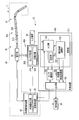
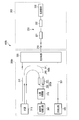
- FIG. 1 is a diagram schematically showing an example of an endoscope system including a curvature information deriving device according to a first embodiment of the present invention.
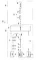
- FIG. 2 is a block diagram illustrating an example of a fiber sensor of the bending information deriving device.
- FIG. 3 is a cross-sectional view including the optical axis of the light guide member of the sensor unit.
- FIG. 4 is a sectional view in the radial direction of the light guide member along the line AA in FIG.
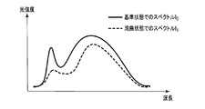
- FIG. 5 is a diagram illustrating an example of the relationship between the wavelength and the light intensity in the reference state and the curved state.
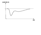
- FIG. 6 is a diagram illustrating an example of the relationship between the wavelength and the change rate of the light intensity.
- FIG. 1 is a diagram schematically showing an example of an endoscope system including a curvature information deriving device according to a first embodiment of the present invention.
- FIG. 2 is a block diagram illustrating an example of a fiber sensor of the bending
- FIG. 7 is a diagram illustrating a curved state of the light guide member having the configuration (I).
- FIG. 8 is a diagram illustrating a curved state of the light guide member having the configuration (II).
- FIG. 9 is a diagram illustrating a curved state of the light guide member having the configuration (III).
- FIG. 10 is a diagram illustrating an example of the relationship between the wavelength and the absorbance in case 1.
- FIG. 11 is a diagram illustrating an example of the relationship between the wavelength and the absorbance in Case 2.
- FIG. FIG. 12 is a diagram illustrating an example of the relationship between the wavelength and the absorbance including the correction value in Case 1.
- FIG. 13 is a diagram illustrating an example of the relationship between wavelength and absorbance, including the correction term in Case 2.
- FIG. 14 is a diagram schematically showing an example of a configuration for determining a correction value for correcting a change over time in the absorption spectrum of the light absorber of the detected portion.
- FIG. 15 is a diagram schematically showing an example of a configuration for determining a correction value for correcting a change over time in the absorption spectrum of the light absorber of the detected portion.
- FIG. 16 is a diagram schematically showing an example of a configuration for determining a correction value for correcting a change with time of the absorption spectrum of the light absorber of the detected portion.
- FIG. 17 is a diagram schematically illustrating an example of an endoscope system including a curvature information deriving device for determining a correction value for correcting a change over time of an absorption spectrum of a light absorber of a detected portion. It is.
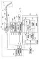
- FIG. 1 is a diagram schematically showing an example of an endoscope system 1 including a curvature information deriving device 10 according to a first embodiment of the present invention.
- the endoscope system 1 includes a bending information deriving device 10, an endoscope device 20, an input device 50, and a display device 60.
- the endoscope device 20 includes an endoscope 30 and an endoscope control device 40.
- the endoscope 30 is connected to the endoscope control device 40 via a universal cord (not shown).
- the endoscope 30 has an insertion portion 31 to be inserted into the insertion object and an operation portion 32 connected to the proximal end side of the insertion portion 31.
- the insertion portion 31 is an elongated tubular portion on the distal end side of the endoscope and has flexibility.
- the insertion portion 31 incorporates an illumination optical system, an observation optical system, an image sensor, and the like (not shown) at the distal end.
- the insertion portion 31 includes a bending portion that bends in a desired direction when the user operates the operation portion 32.
- Various operations of the endoscope 30 including the bending operation are input to the operation unit 32.
- the endoscope control device 40 includes an endoscope light source 41 for supplying illumination light to the illumination optical system of the endoscope 30.
- the endoscope light source 41 includes general light emitting elements such as a halogen lamp, a xenon lamp, a laser diode (LD), and a light emitting diode (LED).
- the endoscope control device 40 includes the endoscope 30 and the endoscope 30, such as drive control of the imaging element of the endoscope 30, drive control of the endoscope light source 41, and dimming control of illumination light from the endoscope light source 41.
- Various operations of the endoscope light source 41 are controlled.
- the endoscope control device 40 includes an image processing unit 42 for processing an image acquired by the observation optical system and the imaging element of the endoscope 30.
- the bending information deriving device 10 is a device for deriving bending information of the insertion portion 31 of the endoscope 30.
- the bending direction and the bending magnitude are collectively referred to as bending information.
- the bending information deriving device 10 includes a control device 100 and a fiber sensor 400 including a sensor unit 200 and a sensor control unit 300. Details of these will be described later.
- the input device 50 is a general input device such as a keyboard and a mouse.
- the input device 50 is connected to the control device 100 of the bending information deriving device 10.
- the input device 50 is used for a user to input various commands for operating the bending information deriving device 10.
- the input device 50 may be a storage medium. In this case, information stored in the storage medium is input to the control device 100.
- the display device 60 is a general monitor such as a liquid crystal display.
- the display device 60 is connected to the endoscope control device 40 and displays an observation image acquired by the endoscope 30.
- the display device 60 is connected to the bending information deriving device 10 and displays the bending information obtained thereby, the bending shape of the insertion portion 31, and the like.
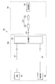
- FIG. 2 is a block diagram illustrating an example of a fiber sensor 400 including the sensor unit 200 and the sensor control unit 300.
- the sensor unit 200 includes a light guide member 210, at least one detected portion 220 provided on the light guide member 210, and a reflection member 230.
- the sensor control unit 300 includes a sensor light source 310, a photodetector 320, and a light branching unit 330.
- the light guide member 210 is an optical fiber, for example, and has flexibility.
- the base end of the light guide member 210 is connected to the light branching unit 330 of the sensor control unit 300.
- the light guide member 210 is incorporated in the insertion portion 31 of the endoscope 30 along the longitudinal direction thereof.
- At least one detected portion 220 of the light guide member 210 is arranged at a point or a region where the bending information should be obtained in the insertion portion 31.
- the 1 and 2 show a plurality of detected parts 220.
- These detected portions 220 include a first detected portion 221 and can further include an m-th detected portion 22m, that is, m light-detecting portions 220 are provided on the light guide member 210. Can do.
- m is an arbitrary number.
- the m detected parts 221 to 22m are arranged at different positions in the longitudinal direction (optical axis direction) of the light guide member 210, that is, spaced from each other.
- FIG. 3 is a cross-sectional view including the optical axis of the light guide member 210.
- 4 is a cross-sectional view in the radial direction of the light guide member 210 taken along the line AA in FIG.
- the light guide member 210 has a three-layer structure including a core 211, a clad 212 surrounding the core 211, and a jacket (covering / buffer) 213 surrounding the clad 212.
- the detected part 220 is formed by removing a part of the jacket 213 and the clad 212 to expose the core 211 and providing the light absorber 214 on the exposed core 211.
- a substance colored with a coloring material (pigment) whose refractive index is larger than the refractive index of the core 211 and smaller than the refractive index of the jacket 213 is used.
- the color material for example, dyes, pigments, and metal nanoparticles are used.
- the reflection member 230 is connected to the tip of the light guide member 210, that is, the side not connected to the light branching unit 330 of the sensor control unit 300.
- the reflection member 230 is, for example, a mirror.
- the reflection member 230 reflects the light transmitted from the proximal end of the light guide member 210 to the distal end so that the light branching portion 330 returns in a certain direction.
- the sensor light source 310 (hereinafter simply referred to as the light source 310) includes, for example, general light emitting elements such as a halogen lamp, a xenon lamp, a laser diode (LD), and a light emitting diode (LED).
- the photodetector 320 is a detector that acquires light intensity for each wavelength (wavelength band), and includes a combination of a spectroscope, a color filter, and a light receiving element.
- the light branching unit 330 is a branching unit that branches light transmitted from the light source 310 to the sensor unit 200 via the light guide member 311 and light transmitted from the sensor unit 200 to the photodetector 320 via the light guide member 321. Yes, including optical couplers, half mirrors, etc.
- the light guide members 311 and 321 may also be flexible optical fibers.
- the light source 310 emits light in a predetermined emission wavelength region.
- the emitted light is guided from the light guide member 311 to the light guide member 210 via the light branching unit 330, reflected by the reflecting member 230 and turned back, and again guided from the light guide member 210 via the light branching unit 330.
- the light is guided to the member 321 and reaches the photodetector 320.
- the light detector 320 shows the relationship between the spectrum of light that has passed through the detected portion 220 (221 to 22m), reflected by the reflecting member 230, and returned, that is, the wavelength in a predetermined wavelength region and the light intensity (light quantity).
- the detected light quantity information is detected.
- the light absorber 214 absorbs light having a predetermined wavelength (wavelength band) among the light transmitted through the light guide member 210. For example, when the detected part 220 is in a straight state, part of the light guided through the light guide member 210 is absorbed by the light absorber 214. On the other hand, when the light guide member 210 is curved so that the detected portion 220 is located inside the bend, the amount of light hitting the light absorber 214 decreases, so the amount of light absorbed by the light absorber 214 is small. Become.
- the transmission amount of the light transmitted through the light guide member 210 is larger than that in the linear state.
- the amount of light hitting the light absorber 214 increases, and the amount of light absorbed by the light absorber 214 increases. Therefore, the transmission amount of light transmitted through the light guide member 210 is smaller than that in the linear state.
- the detected portion 220 modulates the light transmitted through the light guide member 210 according to the curved state of the detected portion 220.
- the light absorber 214 of the detected portion 220 modulates the amount of light (light intensity) transmitted through the light guide member 210.
- the amount of light transmitted by the light guide member 210 changes because the amount of light absorbed by the light absorber 214 of the detected portion 220 changes according to the curved state of the detected portion 220.
- the curvature information deriving device 10 derives the curvature information of the detected part 220 using this light amount change, that is, based on the spectrum detected by the photodetector 320, that is, the detected light amount information.
- the light absorbers 214 having different light absorptance at each wavelength, that is, having different light modulation characteristics, are detected portions 220. Applies to That is, the same number of different types of light absorbers 214 as the number of detected portions 221 to 22m can be prepared. In this case, the characteristics of the absorption spectrum of each light absorber 214 (the relationship between the wavelength and the amount of light absorption) differ in each of the detected parts 221 to 22m.
- the control device 100 is configured by an electronic computer that is a personal computer, for example.
- the control device 100 includes an input unit 110, a storage unit 120, a bending information calculation unit 130, an endoscope shape calculation unit 140, a sensor driving unit 150, and an output unit 160.
- the input unit 110, the storage unit 120, and the bending information calculation unit 130 constitute a calculation unit 101.
- the control device 100 is communicably connected to the endoscope control device 40. In FIG. 1, the control device 100 of the bending information deriving device 10 and the endoscope control device 40 are separated, but the control device 100 may be incorporated in the endoscope control device 40.
- the above-described detected light amount information is input to the input unit 110 from the photodetector 320 of the sensor control unit 300.
- the input unit 110 transmits the detected light amount information to the bending information calculation unit 130.
- the information output from the endoscope control device 40 is also input to the input unit 110.
- information input to the input device 50 is also input to the input unit 110.
- the input unit 110 transmits a signal including the input information to the bending information calculation unit 130 or the sensor driving unit 150.
- the storage unit 120 stores various information necessary for the calculation performed by the bending information calculation unit 130.
- the storage unit 120 stores, for example, a program including a calculation algorithm.
- the bending information calculation unit 130 calculates the bending information of each detected unit 220 based on information such as the detected light amount information acquired via the input unit 110 and information, calculation formulas, and the like stored in the storage unit 120. calculate.
- the bending information calculation unit 130 transmits the calculated bending information of the detected unit 220 to the endoscope shape calculation unit 140 and the output unit 160.
- the bending information calculation unit 130 outputs information related to the operation of the photodetector 320 necessary for calculating bending information, such as the gain of the photodetector 320, to the sensor driving unit 150.
- the endoscope shape calculation unit 140 includes, for example, a CPU or an ASIC.
- the endoscope shape calculation unit 140 determines the shape of the insertion unit 31 of the endoscope 30 in which the detected unit 220 is arranged based on the bending information of each detected unit 220 calculated by the bending information calculation unit 130. calculate.
- the calculated shape of the insertion unit 31 is transmitted to the output unit 160.
- the endoscope shape calculation unit 140 may be incorporated in the bending information calculation unit 130.
- the sensor driving unit 150 generates a driving signal for the photodetector 320 based on the information acquired from the input unit 110 or the bending information calculation unit 130. Based on this drive signal, the sensor drive unit 150 switches the on / off of the light detector 320 based on, for example, a user instruction input to the input device 50 acquired via the input unit 110, or a bending information calculation unit. Based on the information acquired from 130, the gain of the photodetector 320 is adjusted. The sensor driving unit 150 also controls the operation of the light source 310. The sensor drive unit 150 transmits the generated drive signal to the output unit 160.
- the output unit 160 outputs the bending information of the detected unit 220 acquired from the bending information calculation unit 130 or the shape of the insertion unit 31 acquired from the endoscope shape calculation unit 140 to the display device 60. Further, the output unit 160 outputs the bending information of the detected unit 220 acquired from the bending information calculation unit 130 or the shape of the insertion unit 31 acquired from the endoscope shape calculation unit 140 to the endoscope control device 40. Further, the output unit 160 outputs a drive signal from the sensor drive unit 150 to the photodetector 320.
- the insertion part 31 of the endoscope 30 is inserted into the body to be inserted by the user. At this time, the insertion portion 31 bends following the bending state of the inserted body.
- the endoscope 30 obtains an image signal by an observation optical system and an image sensor provided at the distal end of the insertion portion 31, and the obtained image signal is transmitted to the endoscope control device 40.
- the endoscope control device 40 creates an observation image by the image processing unit 42 based on the acquired image signal, and causes the display device 60 to display the created observation image.
- the user wants to display the bending information of the insertion portion 31 of the endoscope 30 on the display device 60 or when the user wants the endoscope control device 40 to perform various operations using the bending information of the insertion portion 31, the user This is input to the control device 100 by the input device 50. At this time, the bending information deriving device 10 operates.
- the light source 310 of the sensor control unit 300 is activated based on the drive signals transmitted to the sensor drive unit 150, the output unit 160, and the sensor control unit 300.
- the light source 310 emits light in a predetermined emission wavelength region. Then, as described above, the amount of light transmitted through the light guide member 210 changes according to the curved state of the detected portion 220, and the changed light intensity is detected for each wavelength by the photodetector 320. That is, the light detector 320 acquires detected light amount information.
- the light detector 320 transmits the acquired detected light amount information to the input unit 110 of the control device 100.
- the transmitted detected light amount information is acquired by the bending information calculation unit 130, and the bending information calculation unit 130 calculates the bending information of each detected unit 220.
- the bending information of each detected unit 220 calculated by the bending information calculation unit 130 is acquired by the endoscope shape calculation unit 140.
- the endoscope shape calculation unit 140 calculates the shape of the insertion part 31 of the endoscope 30 based on the curvature information of the detected part 220.
- the bending information of each detected unit 220 calculated by the bending information calculation unit 130 or the shape of the insertion unit 31 calculated by the endoscope shape calculation unit 140 is acquired by the endoscope control device 40 via the output unit 160. Is done.
- the endoscope control device 40 controls the operation of the endoscope 30 based on the curvature information of the detected part 220 or the shape of the insertion part 31.
- the bending information of each detected unit 220 calculated by the bending information calculation unit 130 or the shape of the insertion unit 31 calculated by the endoscope shape calculation unit 140 is displayed on the display device 60 via the output unit 160.
- the information input to the input unit 110 and the bending information of each detected unit 220 calculated by the bending information calculation unit 130 are acquired by the sensor driving unit 150. Based on the acquired information, the sensor driving unit 150 transmits a driving signal to the photodetector 320 via the output unit 160 to control the operation of the photodetector 320.
- the bending information of each detected unit 220 is derived by the bending information calculation unit 130. Further, the endoscope shape calculation unit 140 calculates the shape of the insertion unit 31 of the endoscope 30 based on the derived curvature information of the detected portion 220. Thereby, the user can obtain the curvature information of each detected portion 220 or the shape of the insertion portion 31 during the operation of the endoscope 30. Further, the endoscope control device 40 can appropriately control the operation of the endoscope 30 according to the calculated curvature information of each detected part 220 or the shape of the insertion part 31.
- a spectrum that is a relationship between the wavelength and the light intensity detected by the photodetector 320 when the detected portion 220 has a predetermined shape as a reference is referred to as a spectrum I 0 in the reference state.
- the reference state refers to, for example, a state where the detected portion 220 is in a straight state, that is, a state where the location of the light guide member 210 including the detected portion 220 is in a straight state. Of course, other states may be used as the reference state.
- An example of the spectrum I 0 in the reference state is shown by a solid line in FIG.
- the spectrum I 0 in the reference state is acquired in advance when the bending information deriving device 10 is shipped from the factory and stored in the storage unit 120, for example. Alternatively, it may be stored in advance in a sensor storage unit (not shown) provided in the sensor unit 200 or the sensor control unit 300. Alternatively, it may be acquired every time the optical branching unit 330 of the sensor control unit 300 and the light guide member 210 of the sensor unit 200 are separated and reconnected, such as during maintenance by a service person.
- the amount of light absorbed by the light absorber 214 of the detected portion 220 changes according to the bending direction and the bending magnitude.
- the spectrum that is the relationship between the wavelength detected by the detector 320 and the light intensity, that is, the spectrum I 1 in the curved state is different from the spectrum I 0 in the reference state.
- An example of the spectrum I 1 in the curved state is shown by a broken line in FIG.
- the change rate I 1 / I 0 shown in FIG. 6 is a change in the spectrum due to the curvature of the detected portion 220.
- the spectrum (the amount of light at each wavelength) changes according to the curved state.
- the spectrum of the light absorber 214 provided in the detected part 220 is acquired by curving the detected part 220.
- the first detected portion 221 and the second detected portion 222 are provided in the light guide member 210.
- the second detected portion 222 including the second light absorber 216, that is, one detected portion, is kept straight without bending the first detected portion 221 including the second light absorber 215.
- the spectrum of the first light absorber 215 is obtained by curving only the light.
- the first detected portion 221 and the second detected portion 222 that are close to each other constitute a detected portion group.
- the other detected portion 222 (or 221) is inevitably bent, and therefore only one detected portion cannot be bent. .
- the detected part 221 or 222 instead of the detected part 221 or 222 itself, an alternative detected part corresponding to the detected part 221 or 222, or the light of the detected part 221 or 222
- the spectrum of the light absorber 215 or 216 of the detected portion 221 or 222 is acquired by another optical characteristic acquisition unit that simulates light absorption by the absorber 215 or 216.
- the solution / dispersion spectrum is obtained by dissolving or dispersing the color material constituting the light absorber 215 or 216 in the liquid.
- the first light absorber provided in the first detected portion 221. 215 and the second light absorber 216 provided in the second detected portion 222 are different light absorbers.
- the same light absorber 216 is provided in the second detected unit 222 and the third detected unit 223 adjacent to each other. In other words, the detected part provided with the same light absorber 216 is divided into two parts.
- the detection range by the light absorber 216 becomes long, the structural strength of the light guide member 210 is maintained, or the fixing portion when the light guide member 210 is fixed to another member Is secured between the second detected portion 222 and the third detected portion 223 (that is, the light guide member 210 is not fixed at the location of the detected portion).
- the same light absorber 216 is provided in the second detected portion 222 and the third detected portion 223 that are curved, as in the configuration (III) of the light guide member 210 shown in FIG.
- the two detected parts 222 and 223 are regarded as one detected part. That is, the configuration (III) is handled in the same manner as the configuration (I), and the two detected parts 222 and 223 in which the same light absorber 216 is arranged are set to the same curved state (curvature).
- the number of detected parts regarded as one detected part may be three or more.
- the configuration (I) For example, in order to acquire the spectrum of the light absorber of each of the detected portions 221 and 222 constituting the detected portion group in the light guide member 210 of the configuration (II), the configuration (I) The light guide member 210 is prepared separately. And the spectrum of the light absorber of each to-be-detected part 221 and 222 is acquired by curving each to-be-detected part 221 and 222 as mentioned above about composition (I).
- the same first light absorber 215 and second light absorber 216 are used for the first detected portion 221 and the second detected portion 222 of the configurations (I) and (II), respectively.
- the absorption spectrum of the light absorbers 215 and 216 of the detected parts 221 and 222 in the configuration (I) and the absorption spectrum of the light absorbers 215 and 216 of the detected parts 221 and 222 in the configuration (II) are completely Does not match (strictly). This is because the absorption spectrum of the color material contained in the light absorber constituting the light absorber in each detected portion changes (case 1) and the addition of new light absorption (scattering). There are two main cases: the case where the absorption spectrum of the light absorber changes (case 2).
- FIG. 10 is a diagram showing an example of the relationship between wavelength and absorbance in Case 1.
- the absorption spectrum Ui in the configuration (I) is indicated by a solid line
- the absorption spectrum Uii in the configuration (II) is indicated by a broken line.
- the maximum values of the absorption spectra Ui and Uii are the same. Comparing the absorption spectrum Ui and the absorption spectrum Uii, for example, the peak wavelength of the absorption spectrum Uii is shifted to the longer wavelength side with respect to the absorption spectrum Ui (change indicated by a right arrow in FIG. 10). Further, for example, the peak of the absorption spectrum Uii changes with respect to the peak of the absorption spectrum Ui (change indicated by the up and down arrows in FIG. 10).
- FIG. 11 is a diagram showing an example of the relationship between wavelength and absorbance in Case 2.
- the absorption spectrum Ui in the configuration (I) is indicated by a solid line
- the absorption spectrum Uii in the configuration (II) is indicated by a broken line. Comparing the absorption spectrum Ui and the absorption spectrum Uii, for example, the absorption spectrum Uii is generally shifted upward with respect to the absorption spectrum Ui (change indicated by an upward arrow in FIG. 11). That is, light absorption occurs as a whole.
- the correct bending information is obtained in the bending information deriving device 10 including the light guide member 210 as in the configuration (II). May not be derived.
- the change rate V of the light amount at each wavelength is expressed by an equation including the absorption spectrum and curvature information of the light absorber constituting the detected part.
- the correction value which is a characteristic value peculiar to each to-be-detected part is given to said formula.
- the absorption spectrum of the light absorber 214 (215, 216) of each detected portion 220 (221, 222) can be acquired as in the configuration (I) (absorption of the light absorber of the detected portion 220 in the configuration (II))
- the light quantity change rate V of the light modulated by the detected portion 220 is the spectrum I 0 in the reference state and the spectrum I 1 in the curved state, including the case where the spectrum is completely equal to the configuration (I). It is expressed as a ratio. That is, the light quantity change rate V is defined by the following equation (1).
- the light quantity change rate V can be expressed using a curvature coefficient as shown in Equation (2).
- V is a light amount change rate of the entire fiber sensor 400, and exists for each wavelength in a predetermined wavelength band of light emitted from the light source 310 (V ⁇ 1 to V ⁇ n).
- V A is a light amount change rate in the first detected unit 221
- V B is a light amount change rate in the second detected unit 222.
- These light quantity change rates V A and V B also exist for each wavelength in a predetermined wavelength band of light emitted from the light source 310 (V A ⁇ 1 to V A ⁇ n, V B ⁇ 1 to V B ⁇ n).
- ⁇ A is a curvature coefficient of the first detected portion 221 and is a function of the curvature and the bending direction.
- ⁇ B is a curvature coefficient of the second detected portion 222 and is a function of the curvature and the bending direction. These curvature coefficients ⁇ A and ⁇ B do not depend on the wavelength, and change depending on the bending direction and size of each detected portion.
- U A is the absorption spectrum of the first light absorber 215 of the first detection target portion 221
- U B is the absorption spectrum of the second light absorber 216 of the second detection target portion 222.
- These absorption spectra U A and U B exist for each wavelength in a predetermined wavelength band of light emitted from the light source 310 (U A ⁇ 1 to U A ⁇ n, U B ⁇ 1 to U B ⁇ n).
- ⁇ A is a curvature coefficient of the first detected portion 221 and is a function of the curvature and the bending direction.
- ⁇ B is a curvature coefficient of the second detected portion 222 and is a function of the curvature and the bending direction.
- the bending information calculation unit 130 of the bending information deriving device 10 performs, for example, the bending coefficients of the first detected unit 221 and the second detected unit 222 and the first light absorption of the first detected unit 221. Acquisition from the storage unit 120 storing the body 215 and the absorption spectrum of the second light absorber 216 of the second detected portion 222 in advance, and further detecting the detected light amount information detected by the photodetector 320
- the curve information of the detected parts 221 and 222 can be derived from the equation (2) representing the relationship between the absorption spectrum, the curve coefficient, and the detected light quantity information.
- U C1 is a correction value of the absorption spectrum of the light absorber 215 of the first detected unit 22
- U C2 is a correction value of the absorption spectrum of the light absorber 216 of the second detected unit 222. is there.
- These correction values U C1 and U C2 of the absorption spectrum also exist for each wavelength in a predetermined wavelength band of the light emitted from the light source 310 (U C1 ⁇ 1 to U c1 ⁇ n, U C2 ⁇ 1 to U C2 ⁇ 2).
- the correction values U C1 and U C2 of the absorption spectra of the light absorbers 215 and 216 in the detected parts 221 and 222 are defined by, for example, the expression (1) when the detected part is bent into various shapes. Is determined together with the curvature coefficients ⁇ A and ⁇ B so that the sum of absolute values of the difference between the light amount change rate V and the light amount change rate V ′ obtained from the equation (3) is minimized ( ⁇ A , ⁇ B is expressed as a function of curvature and bending direction as described above).
- the bending information deriving device 10 uses the fiber sensor 400 to acquire detected light amount information representing the relationship between the wavelength and the light amount in a predetermined wavelength band emitted from the light source 310 by the photodetector 320.
- the fiber sensor 400 includes a light guide member 210 provided with at least one detected portion 220, and light to be transmitted by the detected portion 220 to the light guide member 210 according to the curved state of the detected portion 220. The amount of light is changed. Then, the calculation unit 101 of the control device 100 of the curvature information deriving device 10 acquires the detected light amount information acquired by the photodetector 320.
- the calculation unit 101 obtains, for example, the curvature coefficient of the detected unit 220, the absorption spectrum of the light absorber 214 of the detected unit 220, and the correction value of the absorption spectrum of the light absorber 214 of the detected unit 220. To do. And the calculating part 101 can derive
- the calculation unit 101 absorbs the coloring material by giving a correction value to the calculation formula of the light amount change rate used for calculating the bending information. Even if the spectrum changes, the light amount change rate of the detected portion can be expressed by an expression of a curvature coefficient. Therefore, it is possible to provide a bending information deriving device that can perform correct bending information calculation even when the absorption spectrum changes.
- V D is a light amount change rate in the virtual detection target part and exists for each wavelength in a predetermined wavelength band of light emitted from the light source 310 (V D ⁇ 1 to V D ⁇ n).
- ⁇ D is a curvature coefficient of the virtual detected portion, and is a function of the curvature and the bending direction. This does not depend on the wavelength, and changes depending on the bending direction and size of the virtual detection target portion.
- U D is an absorption spectrum of the light absorber in the virtual detection target part, and exists for each wavelength in a predetermined wavelength band of light emitted from the light source 310 (U D ⁇ 1 to U D ⁇ n).
- ⁇ D is a curvature coefficient of the virtual detected portion, and is a function of the curvature and the bending direction. This does not depend on the wavelength, and changes depending on the bending direction and size of the virtual detection target portion.
- Figure 13 is an absorption spectrum U A light absorbing 215 of the first detection target portion 221 are an example of the absorption spectrum U D of the light absorber virtual detected portion is shown.
- the correction term in this embodiment is determined in the same way as the correction value in the first embodiment.
- a correction term corresponding to each detected part is given.
- a new light absorption is generated in the light absorber by giving a correction term indicating a pseudo virtual detected portion to the light amount change rate used by the bending information calculation unit 130 for calculating the bending information.
- the light amount change rate of the detected portion can be expressed by an equation of a curvature coefficient. Therefore, it is possible to provide a bending information deriving device that can perform correct bending information calculation even when new light absorption occurs.
- Equation (5) a correction value and a correction term are given as shown in Equation (5) by combining the first embodiment and the second embodiment.
- the correction value and the correction term can be determined in the same way as in the first embodiment and the second embodiment.
- a correction value corresponding to each color material and a correction term corresponding to each detected part group may be given.
- the amount-of-light change rate of the detection target group can be expressed by the equation of the curvature coefficient. It is possible to provide a bending information deriving device that can express the bending state correctly.
- the bending information estimation device represents the change rate of the light amount at each wavelength by the relational expression between the absorption spectrum of the light absorber constituting the detected portion and the bending information.
- the absorption of the light absorber is obtained by giving at least one of a correction value and a correction term (characteristic value peculiar to the detected portion) for correcting individual differences and variations in the absorption spectrum of the light absorber to the relational expression. Even if there are individual differences and variations in the spectrum, it is possible to accurately derive the curvature information of the detected portion.
- the control device 100 notifies an error code or a notification that the derivation accuracy is low when at least one of the correction value and the correction term exceeds the set range. It may be configured to notify the user audibly or visually.
- UP1 is a value for correcting the change due to the light energy of the absorption spectrum of the first light absorber 215 of the first detected portion 221.
- U O1 is a value for correcting a change due to oxidation of the absorption spectrum of the first light absorber 215 of the first detected portion 221.
- U T1 is a value for correcting a change in the absorption spectrum of the first light absorber 215 of the first detected portion 221 due to heat.
- UP2 is a value for correcting a change due to light energy in the absorption spectrum of the second light absorber 216 of the second detected portion 222.
- U O2 is a value for correcting a change due to oxidation of the absorption spectrum of the second light absorber 216 of the second detected portion 222.
- U T2 is a value for correcting a change due to heat in the absorption spectrum of the second light absorber 216 of the second detected portion 222.
- correction values U P2, U O2, U T2 is also present for each wavelength in the predetermined wavelength band of the light emitted from the light source 310 (U P2 ⁇ 1 ⁇ U P2 ⁇ n, U O2 ⁇ 1 ⁇ U O2 ⁇ n, U T2 ⁇ 1 to U T2 ⁇ n).
- U P2 ⁇ 1 ⁇ U P2 ⁇ n, U O2 ⁇ 1 ⁇ U O2 ⁇ n, U T2 ⁇ 1 to U T2 ⁇ n it is not necessary to use all these six correction values, and it is not necessary to give a correction value that is not affected by light energy, oxidation, or heat, or small enough to ignore the influence (set to 0).
- the reference light absorber is arranged in an environment equivalent to the detected unit 220 or an environment in which the environment of the detected unit 220 can be estimated. Then, by measuring the absorption spectrum of the reference light absorber, the amount of change in the absorption spectrum of the light absorber 214 of the detected portion 220 is derived. For example, in an equivalent environment, the derived change amount is used as the correction value. For example, if the environment can be estimated, the correction value is obtained from the derived change amount.
- the environment in which the environment of the detected unit 220 can be estimated is, for example, an environment where a known light intensity (for example, 20% light intensity) of the detected unit 220 is given.
- FIG. 14 is a diagram schematically showing an example of a configuration for determining a correction value for correcting a change over time in the absorption spectrum of the light absorber of the detected portion 220.
- a fiber sensor 400a including the sensor unit 200 and the sensor control unit 300a determines a correction value for correcting the change with time of the absorption spectrum of the light absorber of the detected unit 220.
- the sensor control unit 300a of the fiber sensor 400a includes, for example, a flexible optical fiber in addition to the light source 310, the photodetector 320, and the light branching unit 330 similar to those described in the first embodiment. It has an optical member 340, a detected part 350 provided on the light guide member 340, and a reference photodetector 360. The proximal end of the light guide member 340 is connected to the light source 310, and the distal end is connected to the reference photodetector 360.
- the detected part 350 provided in the light guide member 340 has the same configuration as the detected part 220 provided in the light guide member 210.
- the detected portion 350 includes a reference light absorber that absorbs light in a predetermined wavelength band that is emitted from the light source 310 and guided through the light guide member 340.
- the reference light absorber is the same type as the light absorber of the detected portion 220.
- the reference photodetector 360 is a detector that acquires light intensity for each wavelength (wavelength band), and includes a combination of a spectroscope, a color filter, and a light receiving element.
- the detected light amount information detected by the reference photodetector 360 is output to the control device 100 in the same manner as the detected light amount information detected by the photodetector 320.
- the temporal change of the light absorber due to the light energy, oxidation, and heat given to the detected part 220 occurs more slowly than the one-time use of the endoscope (a few hours at the longest). Therefore, when the endoscope 30 is connected to the bending information deriving device 10, for example, the light branching unit 330 of the sensor control unit 300 and the light guide member 210 of the sensor unit 200 are connected. Sometimes you can do it.
- the acquisition of the correction value is performed by the control device 100, for example, and the acquired correction value is stored in the storage unit 120, for example. Alternatively, a correction value may be acquired separately, and the value may be input from the input device 50 and stored in the storage unit 120. If more precise correction is required, correction values may be acquired at regular intervals such as every 30 minutes.
- the form of the detected portion 350 including the reference light absorber is the same as that of the detected portion 220 as shown in FIG. 14, and the transmitting member coated on the glass plate and the reflecting member coated on the mirror The form of the filter containing these may be sufficient.
- the detected part 350 including the reference light absorber has the same form as the detected part 220 and is placed in the same environment as the detected part 220 and performs the acquisition operation as described above, the reference light The amount of change in the absorption spectrum of the absorber is used as a correction value. Further, if the reference light absorber is a structure such as a filter or an environment in which the environment of the detected part can be estimated, the obtained change amount of the absorption spectrum of the reference light absorber is stored in the storage unit 120. Then, the bending information calculation unit 130 obtains the correction value by converting the amount of change.
- the bending information calculation unit 130 of the control device 100 acquires the absorption spectrum of the reference light absorber of the detected unit 350 using, for example, the photodetector 320 such as a spectroscope, and performs initial processing.
- a correction value is obtained by obtaining a change amount of the acquired absorption spectrum with respect to an absorption spectrum in a state (for example, at the time of factory shipment).
- the bending information calculation unit 130 uses the obtained correction value to calculate the bending information of the detected unit 220 from the above equation (6) in the same procedure as in the first to third embodiments.
- FIG. 15 schematically shows an example of a configuration for determining a correction value for correcting the change over time of the absorption spectrum of the light absorber of the detected part 220 (two detected parts 221 and 222).
- a fiber sensor 400b including the sensor unit 200 and the sensor control unit 300b determines a correction value for correcting a change over time in the absorption spectrum of the light absorber of the detected unit 220.
- the sensor control unit 300b of the fiber sensor 400b includes a light source 310, a photodetector 320, and an optical branching unit 330 similar to those described in the first embodiment, for example, a guide that is a flexible optical fiber.
- the proximal ends of the light guide members 341 and 342 are connected to the light source 310, and the distal ends are connected to the optical path switch 370.
- the detected part 351 provided in the light guide member 341 has the same configuration as the first detected part 221 provided in the light guide member 210, and the detected part 352 is the second detected part.
- the configuration is the same as that of 222. That is, each of the detected parts 351 and 352 includes a reference light absorber that absorbs light in a predetermined wavelength band that is emitted from the light source 310 and guided through the light guide members 341 and 342.
- the reference light absorbers of the detected portions 351 and 352 are the same type as the light absorbers of the detected portions 221 and 222, respectively, and are different from each other.
- the reference photodetector 360 is a detector that acquires light intensity for each wavelength (wavelength band), and includes a combination of a spectroscope, a color filter, and a light receiving element.
- the detected light amount information detected by the reference photodetector 360 is output to the control device 100 in the same manner as the detected light amount information detected by the photodetector 320.
- the optical path switch 370 switches the optical path of the light from the light guide members 341 and 342.
- the reference photodetector 360 may be disposed at the tip of each of the light guide members 341 and 342. This eliminates the need for the optical path switch 370 and eliminates the need to switch the optical path.
- the optical path may be switched using the photodetector 320. This also reduces the number of photodetectors arranged in the fiber sensor 400b. Moreover, it is not necessary to consider the influence of the sensitivity of the photodetector.
- the fiber sensor 400 is fixed in a predetermined shape, for example, a linear shape, and the absorption spectrum of the reference light absorber is acquired in a state where the fiber sensor 400 cannot be bent.
- a predetermined shape for example, a linear shape
- the reference light absorber When the reference light absorber is in the form of a filter, measurement is performed at a predetermined film thickness of the reference light absorber. Absent).
- the location of the predetermined film thickness to be measured may be one location, or may be measured at a plurality of locations having the same thickness and averaged. Alternatively, measurement may be performed at a plurality of locations with different film thicknesses, and the correction value may be obtained from the difference. Alternatively, the correction value may be obtained from the difference in the color material concentration of the light absorber and the difference in the number of filter structures.
- FIG. 16 is a diagram schematically illustrating an example of a configuration for determining a correction value for correcting a change over time in the absorption spectrum of the light absorber of the detected unit 220 (detected units 221 to 22m). is there.
- the correction value for correcting the change with time of the absorption spectrum of the light absorber of the detection target 220 is determined by the fiber sensor 400c including the sensor unit 200 and the sensor control unit 300c.
- the sensor control unit 300c of the fiber sensor 400c includes, for example, a flexible optical fiber in addition to the light source 310, the light detector 320, and the light branching unit 330 similar to those described in the first embodiment. It has an optical member 340c, a detected portion 350c provided on the light guide member 340c, and a reference photodetector 360. The proximal end of the light guide member 340 c is connected to the light source 310, and the distal end is connected to the reference photodetector 360.
- each of the detected parts 351 to 358 has the same configuration as the first to m-th detected parts 221 to 22m provided in the light guide member 210. That is, each of the detected portions 351 to 35m includes a reference light absorber that absorbs light in a predetermined wavelength band that is emitted from the light source 310 and guided through the light guide member 340c.
- the reference light absorbers of the detected portions 351 to 358 are the same type as the light absorbers of the detected portions 221 to 22m, and are different from each other.
- the number of the light guide members 340c is not limited to one, and two light guide members 340c having four detected portions (light absorbers for reference) arranged may be prepared. Good.
- the detection target 350c including all the reference light absorbers arranged on the same light guide member 340c is fixed in a predetermined shape, for example, a linear shape, and then the measurement target is detected. Only the portion is curved, and the absorption spectrum of the reference light absorber is acquired by the reference photodetector 360. And the curvature information calculating part 130 calculates a correction value by calculating
- reference light absorbers corresponding to all the detected portions 220 (221 to 22m) are prepared. However, in the following method 1-3, some of the detected portions are detected. Only a reference light absorber corresponding to 220 (a part of representative colors) is prepared.
- Method 1-3 Arrange only some reference light absorbers
- the relationship of changes with time between the respective reference light absorbers each color
- the change in the second color and the third color can be estimated from the change in the first color.
- a relational expression for estimating the change is stored in advance in the storage unit 120 of the control device 100 or input from the input unit 110. Then, for example, the calculation unit 101 of the control device 100 determines a correction value for a light absorber that is not prepared using the relational expression for this estimation.
- the reference photodetector of the sensor control unit measures the change in the absorption spectrum of the two colors.
- the change in the absorption spectrum of the other colors is calculated by the calculation unit 101 estimating from the change in the absorption spectra of the two colors. Then, the calculation unit 101 determines a correction value for correcting the change with time of the absorption spectrum of the light absorber of the detected unit 220.
- a color material that is easy to evaluate the influence of change over time may be used instead of the color material actually used for the light absorber of the detected portion.
- the relationship of change with time of each color material is known.
- Method 2 Correction value is determined by estimation
- the correction values U Pn , U On , and U Tn are determined by estimation without arranging a reference light absorber.
- FIG. 17 schematically illustrates an example of an endoscope system 1d including a curvature information deriving device 10d for determining a correction value for correcting a change over time in the absorption spectrum of the light absorber of the detected portion 220.
- the bending information deriving device 10d includes a fiber sensor 400d including a sensor unit 200 and a sensor control unit 300d.
- the sensor control unit 300 d includes an integrated drive time measurement unit 381, a light intensity measurement unit 382, and an elapsed time measurement unit 383.
- the integrated drive time measuring unit 381 is, for example, an hour meter.
- the light intensity measurement unit 382 is, for example, an optical power meter.
- the elapsed time measuring unit 383 is, for example, a clock.
- the storage unit 33 is provided in the operation unit 32 of the endoscope 30d.
- the storage unit 33 stores information on the date of manufacture of the endoscope 30d, information on the number of uses of the endoscope 30d, and the like.
- a temperature sensor 500 is disposed on the light guide member 210 of the sensor unit 200.
- the temperature sensor 500 is preferably arranged in the vicinity of the detected part 220.
- the change in the absorption spectrum due to light energy can be estimated by the integrated amount of the applied light energy. That is, the calculation unit 101 of the control device 100 integrates the light intensity of the light source 310 measured by the light intensity measurement unit 382 or the drive current of the light source 310 (or the indicated value from the control device 100) by an ammeter (not shown). Based on the accumulated drive time measured by the drive time measuring unit 381 and the information stored in the storage unit 33, a correction value UPn for correcting a change in the absorption spectrum due to light energy is calculated. The calculated correction value UPn is stored in the storage unit 120 and used for derivation of bending information by the bending information calculation unit 130.
- the change in the absorption spectrum due to oxidation can be estimated from the elapsed time from the production. That is, the calculation unit 101 of the control device 100 estimates the elapsed time based on the information of the elapsed time measurement unit 383 that measures the elapsed time from the time of manufacture and the storage unit 33 of the endoscope 30d, and absorbs by oxidation. A correction value U On for correcting the change in the spectrum is calculated. The calculated correction value U On is also stored in the storage unit 120 and used for derivation of bending information by the bending information calculation unit 130.
- the change in the absorption spectrum due to heat can be estimated from the integrated amount of heat applied to the light absorber 214 of the detected portion 220. That is, the calculation unit 101 of the control device 100 has a temperature in the vicinity of the detected portion 220 measured by the temperature sensor 500, an accumulated drive time measured by the accumulated drive time measuring unit 381, and information stored in the storage unit 33.
- the correction value UPn for correcting the change in the absorption spectrum due to oxidation is calculated.
- the calculated correction value correction value UPn is stored in the storage unit 120 and used for derivation of bending information by the bending information calculation unit 130.
- the control device 100 audibly notifies that error code or that the derivation accuracy is lowered. It may be configured to notify the user visually or visually.
- the absorption spectrum of the light absorber 414 provided in the detected part 420 changes with time, the influence of the absorption spectrum due to light energy, oxidation, or heat is measured. It is possible to provide a bending information deriving device capable of correctly deriving bending information by deriving bending information from a relational expression obtained by directly deriving more directly or by estimation and adding a correction value based thereon. it can.
Landscapes
- Health & Medical Sciences (AREA)
- Life Sciences & Earth Sciences (AREA)
- Surgery (AREA)
- Physics & Mathematics (AREA)
- Engineering & Computer Science (AREA)
- Biomedical Technology (AREA)
- Animal Behavior & Ethology (AREA)
- Radiology & Medical Imaging (AREA)
- Optics & Photonics (AREA)
- Nuclear Medicine, Radiotherapy & Molecular Imaging (AREA)
- Biophysics (AREA)
- Heart & Thoracic Surgery (AREA)
- Medical Informatics (AREA)
- Molecular Biology (AREA)
- Pathology (AREA)
- General Health & Medical Sciences (AREA)
- Public Health (AREA)
- Veterinary Medicine (AREA)
- Signal Processing (AREA)
- General Physics & Mathematics (AREA)
- Instruments For Viewing The Inside Of Hollow Bodies (AREA)
- Endoscopes (AREA)
Abstract
La présente invention concerne un dispositif de déduction d'informations de courbure dans lequel une unité de calcul acquiert des informations de quantité de lumière de détection indiquant la relation entre des quantités de lumière et des longueurs d'onde dans une région de longueur d'onde prédéterminée, lesdites informations de quantité de lumière de détection étant acquises au moyen d'un capteur, qui comporte un élément de guidage de lumière qui est pourvu d'au moins une section à détecter, et dans lequel la section à détecter modifie, en fonction de l'état incurvé de la section à détecter, la quantité de lumière transmise dans l'élément de guidage de lumière. Sur la base du spectre d'absorption de chaque section à détecter, d'un coefficient de courbure de chaque section à détecter, dudit coefficient de courbure changeant en raison de la direction et de l'amplitude de la courbure de chaque section à détecter, et de valeurs caractéristiques inhérentes à chaque section à détecter, l'unité de calcul déduit des informations de courbure indiquant la direction et l'amplitude de la courbure de chaque section à détecter. En outre, l'invention concerne un système d'endoscope comprenant le dispositif, et un procédé de déduction d'informations de courbure.
Priority Applications (2)
| Application Number | Priority Date | Filing Date | Title |
|---|---|---|---|
| PCT/JP2016/087944 WO2018116375A1 (fr) | 2016-12-20 | 2016-12-20 | Dispositif de déduction d'informations de courbure, système d'endoscope comprenant celui-ci, et procédé de déduction d'informations de courbure |
| US16/445,633 US11399697B2 (en) | 2016-12-20 | 2019-06-19 | Bend information computation apparatus, endoscope system including the apparatus, and bend information computation method |
Applications Claiming Priority (1)
| Application Number | Priority Date | Filing Date | Title |
|---|---|---|---|
| PCT/JP2016/087944 WO2018116375A1 (fr) | 2016-12-20 | 2016-12-20 | Dispositif de déduction d'informations de courbure, système d'endoscope comprenant celui-ci, et procédé de déduction d'informations de courbure |
Related Child Applications (1)
| Application Number | Title | Priority Date | Filing Date |
|---|---|---|---|
| US16/445,633 Continuation US11399697B2 (en) | 2016-12-20 | 2019-06-19 | Bend information computation apparatus, endoscope system including the apparatus, and bend information computation method |
Publications (1)
| Publication Number | Publication Date |
|---|---|
| WO2018116375A1 true WO2018116375A1 (fr) | 2018-06-28 |
Family
ID=62626972
Family Applications (1)
| Application Number | Title | Priority Date | Filing Date |
|---|---|---|---|
| PCT/JP2016/087944 WO2018116375A1 (fr) | 2016-12-20 | 2016-12-20 | Dispositif de déduction d'informations de courbure, système d'endoscope comprenant celui-ci, et procédé de déduction d'informations de courbure |
Country Status (2)
| Country | Link |
|---|---|
| US (1) | US11399697B2 (fr) |
| WO (1) | WO2018116375A1 (fr) |
Citations (5)
| Publication number | Priority date | Publication date | Assignee | Title |
|---|---|---|---|---|
| JP2015029831A (ja) * | 2013-08-06 | 2015-02-16 | オリンパス株式会社 | 挿入システム及び形状センサの形状検出特性を調整する方法 |
| JP2016007506A (ja) * | 2014-06-26 | 2016-01-18 | オリンパス株式会社 | 形状推定装置、それを備えた内視鏡システム、形状推定方法及び形状推定のためのプログラム |
| JP2016007505A (ja) * | 2014-06-26 | 2016-01-18 | オリンパス株式会社 | 形状推定装置、形状推定装置を備えた内視鏡システム、形状推定方法及び形状推定のためのプログラム |
| WO2016178279A1 (fr) * | 2015-05-01 | 2016-11-10 | オリンパス株式会社 | Appareil de déduction d'informations de flexion, système d'endoscope équipé de l'appareil de déduction d'informations de flexion, procédé de déduction d'informations de flexion, et programme de déduction d'informations de flexion |
| WO2016194059A1 (fr) * | 2015-05-29 | 2016-12-08 | オリンパス株式会社 | Capteur de courbure et dispositif d'endoscope pourvu de celui-ci |
Family Cites Families (4)
| Publication number | Priority date | Publication date | Assignee | Title |
|---|---|---|---|---|
| US7772541B2 (en) * | 2004-07-16 | 2010-08-10 | Luna Innnovations Incorporated | Fiber optic position and/or shape sensing based on rayleigh scatter |
| JP4714570B2 (ja) | 2005-11-24 | 2011-06-29 | Hoya株式会社 | 内視鏡形状検出プローブ |
| CN102196761B (zh) * | 2008-10-28 | 2014-03-12 | 奥林巴斯医疗株式会社 | 医疗设备 |
| JP6153385B2 (ja) * | 2013-05-29 | 2017-06-28 | オリンパス株式会社 | 校正補助装置、湾曲システム及び校正方法 |
-
2016
- 2016-12-20 WO PCT/JP2016/087944 patent/WO2018116375A1/fr active Application Filing
-
2019
- 2019-06-19 US US16/445,633 patent/US11399697B2/en active Active
Patent Citations (5)
| Publication number | Priority date | Publication date | Assignee | Title |
|---|---|---|---|---|
| JP2015029831A (ja) * | 2013-08-06 | 2015-02-16 | オリンパス株式会社 | 挿入システム及び形状センサの形状検出特性を調整する方法 |
| JP2016007506A (ja) * | 2014-06-26 | 2016-01-18 | オリンパス株式会社 | 形状推定装置、それを備えた内視鏡システム、形状推定方法及び形状推定のためのプログラム |
| JP2016007505A (ja) * | 2014-06-26 | 2016-01-18 | オリンパス株式会社 | 形状推定装置、形状推定装置を備えた内視鏡システム、形状推定方法及び形状推定のためのプログラム |
| WO2016178279A1 (fr) * | 2015-05-01 | 2016-11-10 | オリンパス株式会社 | Appareil de déduction d'informations de flexion, système d'endoscope équipé de l'appareil de déduction d'informations de flexion, procédé de déduction d'informations de flexion, et programme de déduction d'informations de flexion |
| WO2016194059A1 (fr) * | 2015-05-29 | 2016-12-08 | オリンパス株式会社 | Capteur de courbure et dispositif d'endoscope pourvu de celui-ci |
Also Published As
| Publication number | Publication date |
|---|---|
| US20200000311A1 (en) | 2020-01-02 |
| US11399697B2 (en) | 2022-08-02 |
Similar Documents
| Publication | Publication Date | Title |
|---|---|---|
| US5307146A (en) | Dual-wavelength photometer and fiber optic sensor probe | |
| US8102537B2 (en) | Optical displacement gage | |
| JP5060678B2 (ja) | 光学式変位計 | |
| JP6322495B2 (ja) | 形状推定装置、形状推定装置を備えた内視鏡システム及び形状推定のためのプログラム | |
| US10842359B2 (en) | Curvature sensor and endoscope apparatus equipped with the same | |
| CN107529941A (zh) | 弯曲信息导出装置、具有弯曲信息导出装置的内窥镜系统、弯曲信息导出方法和弯曲信息导出用的程序 | |
| US9182339B2 (en) | Calibration apparatus and calibration method | |
| WO2017009984A1 (fr) | Dispositif de calcul de forme | |
| US9395251B2 (en) | Temperature sensitive body, optical temperature sensor, temperature measurement device, and heat flux measurement | |
| WO2018116375A1 (fr) | Dispositif de déduction d'informations de courbure, système d'endoscope comprenant celui-ci, et procédé de déduction d'informations de courbure | |
| JP5282599B2 (ja) | 分光感度特性測定装置、および分光感度特性測定方法 | |
| WO2017060956A1 (fr) | Dispositif de calcul de forme | |
| JP6561134B2 (ja) | 湾曲情報導出装置 | |
| US20180192887A1 (en) | Thermochromic Optical Waveguide Temperature Sensors | |
| US11478305B2 (en) | Bend information computation apparatus and endoscope system | |
| JPWO2016075831A1 (ja) | 湾曲情報推定装置、湾曲情報推定装置を備えた内視鏡システム、湾曲情報推定方法及び湾曲情報推定のためのプログラム | |
| WO2017221355A1 (fr) | Dispositif d'estimation de forme | |
| JP6484125B2 (ja) | 温度測定装置及び温度測定方法 | |
| US20190346671A1 (en) | Shape estimation apparatus and shape estimation method | |
| US20230384172A1 (en) | Distributed temperature sensing system with fiber bragg gratings | |
| JP3110139B2 (ja) | 光ファイバ温度センサ | |
| Markvart et al. | Interrogation of FBG sensor by a smartphone | |
| JP2019144160A (ja) | 解析装置および解析方法 | |
| CN114234955A (zh) | 光纤陀螺的标度因数在线补偿系统及方法 | |
| JPH03287050A (ja) | 光学式屈折率測定装置 |
Legal Events
| Date | Code | Title | Description |
|---|---|---|---|
| 121 | Ep: the epo has been informed by wipo that ep was designated in this application |
Ref document number: 16924890 Country of ref document: EP Kind code of ref document: A1 |
|
| NENP | Non-entry into the national phase |
Ref country code: DE |
|
| 122 | Ep: pct application non-entry in european phase |
Ref document number: 16924890 Country of ref document: EP Kind code of ref document: A1 |
|
| NENP | Non-entry into the national phase |
Ref country code: JP |