WO2018110605A1 - 画像処理装置、外界認識装置 - Google Patents
画像処理装置、外界認識装置 Download PDFInfo
- Publication number
- WO2018110605A1 WO2018110605A1 PCT/JP2017/044759 JP2017044759W WO2018110605A1 WO 2018110605 A1 WO2018110605 A1 WO 2018110605A1 JP 2017044759 W JP2017044759 W JP 2017044759W WO 2018110605 A1 WO2018110605 A1 WO 2018110605A1
- Authority
- WO
- WIPO (PCT)
- Prior art keywords
- feature map
- vehicle
- unit
- image processing
- verification
- Prior art date
Links
- 238000012545 processing Methods 0.000 title claims abstract description 69
- 238000012795 verification Methods 0.000 claims abstract description 133
- 238000001514 detection method Methods 0.000 claims abstract description 105
- 238000012937 correction Methods 0.000 claims abstract description 30
- 238000003384 imaging method Methods 0.000 claims abstract 2
- 238000011176 pooling Methods 0.000 description 17
- 238000000034 method Methods 0.000 description 16
- 238000013135 deep learning Methods 0.000 description 13
- 238000003702 image correction Methods 0.000 description 12
- 238000010586 diagram Methods 0.000 description 11
- 238000004364 calculation method Methods 0.000 description 7
- 239000000284 extract Substances 0.000 description 6
- 230000008569 process Effects 0.000 description 6
- 230000002776 aggregation Effects 0.000 description 5
- 238000004220 aggregation Methods 0.000 description 5
- 238000013459 approach Methods 0.000 description 4
- 230000006870 function Effects 0.000 description 4
- 238000000605 extraction Methods 0.000 description 3
- 238000013528 artificial neural network Methods 0.000 description 2
- 230000008859 change Effects 0.000 description 2
- 238000013461 design Methods 0.000 description 2
- 230000012447 hatching Effects 0.000 description 2
- 238000010801 machine learning Methods 0.000 description 2
- 238000012986 modification Methods 0.000 description 2
- 230000004048 modification Effects 0.000 description 2
- 210000002569 neuron Anatomy 0.000 description 2
- 230000002093 peripheral effect Effects 0.000 description 2
- 230000004913 activation Effects 0.000 description 1
- 230000006399 behavior Effects 0.000 description 1
- 230000008901 benefit Effects 0.000 description 1
- 230000008878 coupling Effects 0.000 description 1
- 238000010168 coupling process Methods 0.000 description 1
- 238000005859 coupling reaction Methods 0.000 description 1
- 230000003247 decreasing effect Effects 0.000 description 1
- 230000000694 effects Effects 0.000 description 1
- 238000005516 engineering process Methods 0.000 description 1
- 230000001771 impaired effect Effects 0.000 description 1
- 238000013507 mapping Methods 0.000 description 1
- 238000012544 monitoring process Methods 0.000 description 1
- 238000002360 preparation method Methods 0.000 description 1
- 230000003449 preventive effect Effects 0.000 description 1
- 238000003672 processing method Methods 0.000 description 1
Images


Classifications
-
- G—PHYSICS
- G06—COMPUTING; CALCULATING OR COUNTING
- G06V—IMAGE OR VIDEO RECOGNITION OR UNDERSTANDING
- G06V20/00—Scenes; Scene-specific elements
- G06V20/50—Context or environment of the image
- G06V20/56—Context or environment of the image exterior to a vehicle by using sensors mounted on the vehicle
- G06V20/58—Recognition of moving objects or obstacles, e.g. vehicles or pedestrians; Recognition of traffic objects, e.g. traffic signs, traffic lights or roads
-
- B—PERFORMING OPERATIONS; TRANSPORTING
- B60—VEHICLES IN GENERAL
- B60Q—ARRANGEMENT OF SIGNALLING OR LIGHTING DEVICES, THE MOUNTING OR SUPPORTING THEREOF OR CIRCUITS THEREFOR, FOR VEHICLES IN GENERAL
- B60Q9/00—Arrangement or adaptation of signal devices not provided for in one of main groups B60Q1/00 - B60Q7/00, e.g. haptic signalling
- B60Q9/008—Arrangement or adaptation of signal devices not provided for in one of main groups B60Q1/00 - B60Q7/00, e.g. haptic signalling for anti-collision purposes
-
- G—PHYSICS
- G06—COMPUTING; CALCULATING OR COUNTING
- G06F—ELECTRIC DIGITAL DATA PROCESSING
- G06F18/00—Pattern recognition
- G06F18/20—Analysing
- G06F18/21—Design or setup of recognition systems or techniques; Extraction of features in feature space; Blind source separation
- G06F18/217—Validation; Performance evaluation; Active pattern learning techniques
-
- G—PHYSICS
- G06—COMPUTING; CALCULATING OR COUNTING
- G06T—IMAGE DATA PROCESSING OR GENERATION, IN GENERAL
- G06T1/00—General purpose image data processing
-
- G—PHYSICS
- G06—COMPUTING; CALCULATING OR COUNTING
- G06T—IMAGE DATA PROCESSING OR GENERATION, IN GENERAL
- G06T7/00—Image analysis
-
- G—PHYSICS
- G06—COMPUTING; CALCULATING OR COUNTING
- G06V—IMAGE OR VIDEO RECOGNITION OR UNDERSTANDING
- G06V10/00—Arrangements for image or video recognition or understanding
- G06V10/40—Extraction of image or video features
- G06V10/44—Local feature extraction by analysis of parts of the pattern, e.g. by detecting edges, contours, loops, corners, strokes or intersections; Connectivity analysis, e.g. of connected components
- G06V10/443—Local feature extraction by analysis of parts of the pattern, e.g. by detecting edges, contours, loops, corners, strokes or intersections; Connectivity analysis, e.g. of connected components by matching or filtering
- G06V10/449—Biologically inspired filters, e.g. difference of Gaussians [DoG] or Gabor filters
- G06V10/451—Biologically inspired filters, e.g. difference of Gaussians [DoG] or Gabor filters with interaction between the filter responses, e.g. cortical complex cells
- G06V10/454—Integrating the filters into a hierarchical structure, e.g. convolutional neural networks [CNN]
-
- G—PHYSICS
- G06—COMPUTING; CALCULATING OR COUNTING
- G06V—IMAGE OR VIDEO RECOGNITION OR UNDERSTANDING
- G06V10/00—Arrangements for image or video recognition or understanding
- G06V10/70—Arrangements for image or video recognition or understanding using pattern recognition or machine learning
- G06V10/82—Arrangements for image or video recognition or understanding using pattern recognition or machine learning using neural networks
-
- G—PHYSICS
- G08—SIGNALLING
- G08G—TRAFFIC CONTROL SYSTEMS
- G08G1/00—Traffic control systems for road vehicles
- G08G1/16—Anti-collision systems
-
- B—PERFORMING OPERATIONS; TRANSPORTING
- B60—VEHICLES IN GENERAL
- B60W—CONJOINT CONTROL OF VEHICLE SUB-UNITS OF DIFFERENT TYPE OR DIFFERENT FUNCTION; CONTROL SYSTEMS SPECIALLY ADAPTED FOR HYBRID VEHICLES; ROAD VEHICLE DRIVE CONTROL SYSTEMS FOR PURPOSES NOT RELATED TO THE CONTROL OF A PARTICULAR SUB-UNIT
- B60W2420/00—Indexing codes relating to the type of sensors based on the principle of their operation
- B60W2420/40—Photo or light sensitive means, e.g. infrared sensors
- B60W2420/403—Image sensing, e.g. optical camera
-
- B—PERFORMING OPERATIONS; TRANSPORTING
- B60—VEHICLES IN GENERAL
- B60W—CONJOINT CONTROL OF VEHICLE SUB-UNITS OF DIFFERENT TYPE OR DIFFERENT FUNCTION; CONTROL SYSTEMS SPECIALLY ADAPTED FOR HYBRID VEHICLES; ROAD VEHICLE DRIVE CONTROL SYSTEMS FOR PURPOSES NOT RELATED TO THE CONTROL OF A PARTICULAR SUB-UNIT
- B60W30/00—Purposes of road vehicle drive control systems not related to the control of a particular sub-unit, e.g. of systems using conjoint control of vehicle sub-units, or advanced driver assistance systems for ensuring comfort, stability and safety or drive control systems for propelling or retarding the vehicle
- B60W30/08—Active safety systems predicting or avoiding probable or impending collision or attempting to minimise its consequences
- B60W30/09—Taking automatic action to avoid collision, e.g. braking and steering
Definitions
- the present invention relates to an image processing device and an external environment recognition device.
- Patent Document 1 has a narrow dynamic range of information that can be generally expressed, and is easily affected by ambient brightness. Therefore, in the method of Patent Document 1, it may be difficult to accurately specify the road surface in the image. In such a case, an object such as another vehicle existing around the own vehicle is accurately identified from the captured image. It is difficult to detect.
- An image processing apparatus performs a convolution operation on an input image based on a captured image obtained by capturing with a camera, detects an object, and performs the convolution operation. Based on the obtained feature map, a feature map verification unit for performing feature map verification for verifying the probability that the target object is included in the input image, and a result of the feature map verification by the feature map verification unit in time series A time-series verification unit that performs time-series verification, and a detection result correction unit that corrects the detection result of the object by the object detection unit based on the result of the time-series verification by the time-series verification unit; Is provided.
- An external environment recognition apparatus includes an image processing device, and warns a driver of the host vehicle based on a detection result of the other vehicle corrected by the detection result correction unit. At least one of an alarm signal and a vehicle control signal for controlling the operation of the host vehicle is output.
- the present invention it is possible to accurately detect objects such as other vehicles existing around the host vehicle from the captured image.
- FIG. 1 is a block diagram showing a functional configuration of an image processing apparatus 10 according to the first embodiment of the present invention.
- An image processing apparatus 10 shown in FIG. 1 is mounted on a vehicle and used.
- a vehicle on which the image processing apparatus 10 is mounted is referred to as “own vehicle”, and other vehicles existing around the own vehicle are referred to as “other vehicles”.
- the image processing apparatus 10 is connected to a predetermined position of the host vehicle corresponding to the shooting area, for example, a camera 20 attached to the body of the host vehicle.
- the image processing apparatus 10 includes an image correction unit 101, a priority direction selection unit 102, a vehicle detection unit 103, a feature map verification unit 104, a time series verification unit 105, and a detection result correction unit 106.
- Each function of the image processing apparatus 10 shown in FIG. 1 can be realized by appropriately combining hardware such as a microcomputer and a memory, and various programs executed on the microcomputer.
- the camera 20 shoots another vehicle existing around the host vehicle with a moving image or a still image every predetermined time, and the image correction unit 101 uses each frame or each still image of the acquired moving image as a captured image every predetermined time. Output to.
- the camera 20 can be installed at an arbitrary location of the host vehicle.
- the camera 20 is installed in a part such as a front bumper, a rear bumper, and left and right side mirrors of the host vehicle. Or you may install the camera 20 in the vehicle of the own vehicle.
- the camera 20 may be installed alone, or the other vehicles can be recognized in all areas around the own vehicle. As described above, a plurality of cameras 20 may be installed.
- a fisheye camera is used as the camera 20.
- the fish-eye camera is a camera using a fish-eye lens in which the lens condensing characteristic is greatly shifted to the wide-angle side from the lens used in a normal camera, and has an advantage that the photographing range is wide. In this way, it is preferable in terms of image processing in vehicle detection that a wide range can be photographed at one time with one camera.
- the captured image obtained by the camera 20 is a so-called fish-eye image, the closer to the top, bottom, left and right edges of the captured image corresponding to the position far from the vehicle, the greater the distortion and the lower the resolution. Therefore, there is a problem that the distorted captured image input from the camera 20 is not suitable for vehicle detection.
- the captured image obtained by the camera 20 is input to the image correction unit 101 in the image processing apparatus 10.
- the image correction unit 101 performs distortion correction processing on the captured image (fisheye image) input from the camera 20 to convert the captured image into an image without distortion suitable for vehicle detection.
- a nonlinear local geometric correction method that converts a captured image into an actual spatial mapping using the distortion characteristics of a known fisheye lens, or a distortion coefficient that simply represents the distortion characteristics of a fisheye lens.
- a linear local geometric correction method for correcting a photographed image using the above can be used. In the distortion correction process, there is no problem even if another algorithm is selected.
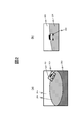
- FIG. 2 is a diagram showing a distortion correction process of a photographed image by the image correction unit 101.
- FIG. 2A is an example of a fish-eye image obtained by photographing with the camera 20 installed on the right side mirror of the host vehicle.
- the left part corresponds to the front, that is, the front direction of the host vehicle
- the right part corresponds to the rear, that is, the rear direction of the host vehicle.
- the road surface 204 is reflected in the center of the image
- the background 205 such as the sky
- the body 203 of the own vehicle is reflected in the lower part of the image.
- the other vehicle 202 is reflected.
- the image correction unit 101 sets, for example, an area including another vehicle 202 as the correction target area 201 for the fish-eye image as shown in FIG. Perform correction processing.
- FIG. 2B is an example of a corrected image obtained by performing distortion correction processing on the correction target area 201 of FIG.
- the other vehicle 202, the road surface 204, and the background 205 are corrected so as to be seen as being equivalent to an actual space map.
- the image correction unit 101 may set an arbitrary area in the captured image as the correction target area. As shown in FIG. Alternatively, a plurality of correction target areas may be set in the captured image, and distortion correction processing may be performed on each of the correction target areas. Furthermore, when performing vehicle detection using a portion with small distortion in the captured image, or when the camera 20 is a normal camera that is not a fisheye camera, the image correction unit 101 does not perform distortion correction processing. May be. In this case, the image processing apparatus 10 may not include the image correction unit 101.
- the priority direction selection unit 102 sets a priority direction that is a direction in which another vehicle, which is a detection target, should be detected preferentially based on the traveling state of the host vehicle. In order to determine the traveling state of the host vehicle, a signal indicating the traveling mode of the host vehicle is input to the priority direction selection unit 102.
- FIG. 3 is a diagram illustrating an example of a setting table used when the priority direction selection unit 102 sets the priority direction.
- the traveling mode of the host vehicle includes forward, backward, and parking assistance.
- different priority directions are shown for the general road and the expressway.
- the priority direction selection unit 102 obtains a signal indicating the travel mode of the host vehicle from a vehicle control CPU mounted on the host vehicle, thereby determining which of the host vehicle travel modes is, It can be determined whether the vehicle is traveling on a general road or an expressway.
- the priority direction selection unit 102 sets a priority direction according to the traveling mode and the traveling road of the host vehicle based on the setting table of FIG. For example, when the traveling mode of the host vehicle is forward, the priority direction selection unit 102 sets the rear of the host vehicle as the priority direction regardless of whether the traveling road is a general road or an expressway. That is, when the host vehicle is moving forward, the rear direction of the host vehicle is set as the priority direction so that other vehicles approaching from the rear of the host vehicle can be detected with priority regardless of the type of the traveling road.
- the priority direction selection unit 102 sets the rear direction of the host vehicle as the priority direction if the traveling road is a general road, and around the host vehicle if the traveling road is an expressway. Set all directions as preferred directions.
- the rear direction of the host vehicle is set as the priority direction so that other vehicles approaching from the rear of the host vehicle can be detected preferentially in the same way as when moving forward. To do. Normally, it is not expected that the host vehicle will retreat on the highway (except in the parking area), but in the unlikely event that such a situation occurs, the risk is high enough so that all directions around the host vehicle are prioritized. By setting as, other vehicles can be detected using the entire captured image.
- the priority direction selection unit 102 sets the front and rear of the host vehicle as the priority direction if the travel road is a general road, and the priority direction selection unit 102 All directions around the vehicle are set as priority directions. That is, when the host vehicle starts parallel parking using parking support on a general road, the front and rear of the host vehicle are preferentially detected so that other vehicles approaching from the front or rear of the host vehicle can be preferentially detected. Set as the preferred direction. Normally, it is not expected that the host vehicle will be parked on the highway (excluding the parking area), but in the unlikely event that such a situation occurs, the risk is sufficiently high. Is set as the priority direction, so that other vehicles can be detected using the entire captured image.
- the priority direction selection unit 102 sets a vehicle detection area for detecting another vehicle that is a detection target in the input image based on the setting result. At this time, the priority direction selection unit 102 sets the vehicle detection area in consideration of the priority direction set for the host vehicle. If the priority direction is not set, a predetermined area in the input image may be set as the vehicle detection area, or the entire input image may be set as the vehicle detection area.
- the vehicle detection unit 103 detects other vehicles that are detection objects existing around the host vehicle from the input image. Detect.
- the vehicle detection unit 103 detects other vehicles reflected in the vehicle detection region by executing a predetermined vehicle detection process on the portion set by the priority direction selection unit 102 in the input image as the vehicle detection region. To do.
- the vehicle detection unit 103 uses a detector to which a deep learning (Deep ⁇ Learning) method, which is a method of machine learning, is used to determine whether an image in the vehicle detection region has a characteristic as a vehicle. By performing the two-class detection for determining whether or not, another vehicle can be detected.
- a deep learning Deep ⁇ Learning
- FIG. 4 is a diagram illustrating an example of a learning image used when generating the detector of the vehicle detection unit 103.
- FIG. 4A is an example of a vehicle learning image
- FIGS. 4B to 4E are examples of non-vehicle learning images.
- the vehicle 300 is reflected, whereas in the learning images of FIGS. 4 (b) to 4 (e), subjects other than the vehicle are reflected.
- the road 301 is shown in the learning image of FIG. 4B
- the tree 302 is shown in the learning image of FIG. 4C
- the building 303 is shown in the learning image of FIG.
- the person 304 is reflected in the learning image of FIG.
- the non-vehicle learning image is not limited to the above example, and any subject other than the vehicle may be reflected.
- a plurality of images of a target object to be detected are input, image features representing the target object are extracted therefrom, and an unknown input image Is a processing method for automatically setting the parameters of the classifier so that the learned image features can be detected and identified.
- an unknown input image Is a processing method for automatically setting the parameters of the classifier so that the learned image features can be detected and identified.
- a feature parameter extraction method a feature extraction method using a neural network structure is known.
- a large number of input / output functions (activation functions) called neuron units that react only when matching the image features common to the input image group are combined for each small image area.
- classifier parameters are extracted for each layer of the neuron unit so that the object can be identified step by step while changing the position and image size of the object to be detected.
- a discriminator parameter capable of discriminating the entire object can be obtained.
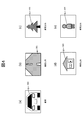
- FIG. 5 is a diagram illustrating an example of a configuration of a deep learning type vehicle detector in the vehicle detection unit 103.
- the deep learning type vehicle detector used for detecting other vehicles in the vehicle detection unit 103 is configured by connecting a plurality of combinations of convolution layers and pooling layers, for example, three stages as shown in FIG.
- the first convolution layer 501 performs a convolution operation on image data corresponding to a portion in the vehicle detection area set by the priority direction selection unit 102 in the image input to the vehicle detection unit 103. Execute, and extract the first-stage feature map 509.
- the first pooling layer 502 aggregates the feature maps 509 extracted by the convolution layer 501 and reduces the data size.
- the second-stage convolution layer 503 performs a convolution operation on the data of the feature map 509 collected by the pooling layer 502 and extracts the second-stage feature map 510.
- the second-stage pooling layer 504 aggregates the feature maps 510 extracted by the convolution layer 503 to reduce the data size.
- the third-stage convolution layer 505 performs a convolution operation on the data of the feature map 510 aggregated by the pooling layer 504, and extracts the third-stage feature map 511.
- the third level pooling layer 506 aggregates the feature maps 511 extracted by the convolution layer 505 to reduce the data size.
- the overall coupling layer 507 identifies whether the input image is another vehicle by comparing the data of the feature map 511 aggregated by the pooling layer 506 with the classifier parameters acquired in advance by deep learning. Output the identification result. As a result, the vehicle detection unit 103 detects another vehicle to be detected from the input image.
- step number of the convolution layer and pooling layer which comprises a vehicle detector in the vehicle detection part 103 is not limited to this.
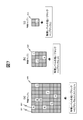
- FIG. 6 is a diagram illustrating an example of a feature map extracted for each convolution layer in the deep learning type vehicle detector illustrated in FIG. Note that the filter size and filter coefficient of the convolution layer and the aggregation coefficient of the pooling layer constituting the deep learning type vehicle detector can be designed arbitrarily, but here, as an example for explanation, each is as follows: Set.
- the size of the input image 600 to the vehicle detector is 32 ⁇ 32 pixels
- the filter coefficient of the first-stage convolutional layer 501 shown in FIG. 5 is indicated by reference numeral 601 in FIG.
- the filter is composed of 16 filter coefficients K1 to K16.
- the filter coefficients of the second-stage convolution layer 503 are configured by eight filter coefficients K17 to K24 as indicated by reference numeral 602 in FIG.
- the filter coefficients of the third-stage convolution layer 505 are composed of four filter coefficients K25 to K28 as indicated by reference numeral 603 in FIG.
- the aggregation coefficients of the first to third pooling layers 502, 504, and 506 shown in FIG. 5 are each set to 1/2.
- a convolution operation using the 16 filter coefficients K1 to K16 is performed on the input image 600 in the first-stage convolution layer 501.
- the first-stage feature map 509 data obtained by combining 16 types of aggregate blocks of 32 ⁇ 32 feature data is obtained.
- the data size is halved and 16 types of 16 ⁇ 16 feature data aggregate blocks are combined. Data is obtained.
- the feature map 509 is converted into a feature map 604 having a half data size.
- the second-stage feature map 510 data obtained by combining eight types of aggregate blocks of 16 ⁇ 16 feature data is obtained.
- the data size is halved, and 8 types of 8 ⁇ 8 feature data aggregate blocks are combined. Data is obtained.
- the feature map 510 is converted into a feature map 605 having a half data size.
- the third-stage convolution layer 505 a convolution operation using four filter coefficients K25 to K28 is performed on the feature map 605.
- the feature map 511 in the third stage data obtained by combining four types of aggregate blocks of 8 ⁇ 8 feature data is obtained.
- the data size is halved and four types of 4 ⁇ 4 feature data aggregate blocks are combined. Data is obtained.
- the feature map 511 is converted into a feature map 606 having a half data size.
- the vehicle detection unit 103 performs a convolution operation a plurality of times on the input image to detect other vehicles that are detection objects.
- the vehicle detection unit 103 outputs information indicating the presence or absence of an image of the other vehicle to the feature map verification unit 104 and the detection result correction unit 106 as the detection result of the other vehicle, for example, in the vehicle detection area set in the input image.
- the filter coefficient used in the convolution calculation of each convolution layer reacts strongly to image features such as vertical lines, horizontal lines, diagonal lines or curves important for image recognition, and extracts only the reacted image feature components. It is a filter numerical value group of image feature extraction set as described above.
- the filter coefficient is set so that the image feature components (the outline of the entire vehicle, the line of the hood, the line of the front window, the shade state of the vehicle body, etc.) constituting the vehicle shown in the input image can be extracted.
- design In filter design using machine learning, common image components included in the majority of input images can be acquired. For this reason, it is possible to automatically extract representative image feature components constituting the vehicle by learning a plurality of input images in which the vehicle is reflected during image learning in the preparation stage, and this can be used as a filter coefficient for convolution calculation. Use.
- the feature map verification unit 104 performs feature map verification to verify the probability that other vehicles are included in the input image, based on the feature maps obtained by the convolution calculation of the vehicle detection unit 103, respectively.
- the feature map verification unit 104 determines, for each of a plurality of blocks constituting the feature map, whether or not the feature of the other vehicle that is the detection target is shown, and compares the determination result with a pre-stored arrangement pattern. Thus, the feature map verification is performed.
- the feature map verification unit 104 performs feature map verification for verifying the probability that the other vehicle is included in the input image based on the arrangement in the feature map of the block where the feature of the other vehicle does not appear.
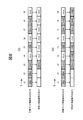
- FIG. 7 is a diagram illustrating an example of feature map verification performed by the feature map verification unit 104.
- the feature maps 509 to 511 obtained by the deep learning type vehicle detector described in FIGS. 5 and 6 are in the states shown in FIGS. 7 (a), 7 (b), and 7 (c), respectively.
- FIGS. 7 (a), 7 (b), and 7 (c) As an example, the operation of feature map verification will be described.
- each block represented by the block 601 indicated by hatching is a block (effective block) from which an effective feature level indicating the feature of another vehicle that is a detection target is obtained. is there.
- each block represented by the other block 602 is a block (invalid block) from which an effective feature level indicating the feature of another vehicle was not obtained.
- the invalid blocks for which no effective feature level appears are eight blocks indicated by A to H.
- each block indicated by hatching represents a valid block
- each other block represents an invalid block.
- the invalid blocks for which the effective feature level did not appear are three blocks indicated by I, J, and K.
- the invalid block for which no valid feature level has appeared is one block indicated by L.
- the feature map verification unit 104 stores in advance feature map arrangement patterns corresponding to the convolutional layers 501, 503, and 505 of FIG. 5 constituting the deep learning type vehicle detector in the vehicle detection unit 103.
- This arrangement map of the feature map represents a pattern of positions where valid blocks indicating features of other vehicles and invalid blocks that do not appear in the feature map.
- the feature map verification unit 104 compares each feature map with the arrangement pattern stored in advance, and based on the comparison result, another vehicle is included in the input image. Verify the likelihood of inclusion.
- the feature map obtained by the convolution calculation of the vehicle detection unit 103 is the presence of other vehicles. Is determined to have a high probability.
- the feature map verification unit 104 outputs a feature map verification signal with the signal value “TRUE”.
- the probability that the feature map obtained by the convolution calculation of the vehicle detection unit 103 indicates the presence of another vehicle. Is determined to be low.
- the feature map verification unit 104 outputs a feature map verification signal with the signal value “FALSE”.
- the feature map verification unit 104 preferably determines an arrangement pattern to be used for comparison of the above feature maps based on the priority direction set by the priority direction selection unit 102. This is because the vehicle detection area is set according to the priority direction, and if the priority direction is different, the image of the other vehicle reflected in the vehicle detection area may change, and the resulting feature map may also change. Because.
- the feature map verification unit 104 stores an arrangement pattern for each priority direction in advance, selects an arrangement pattern corresponding to the set priority direction, and compares it with the feature map. Thereby, even if a vehicle detection area changes according to a priority direction, feature map verification can be performed accurately.
- the time series verification unit 105 performs time series verification to verify the result of the feature map verification by the feature map verification unit 104 in time series.
- this time series verification based on the history of the value of the feature map verification signal output from the feature map verification unit 104, the result of the feature map verification performed by the feature map verification unit 104 is corrected as follows as necessary. To do.
- FIG. 8 is a diagram illustrating an example of time-series verification performed by the time-series verification unit 105.
- the feature map verification unit 104 outputs a feature map verification signal of “TRUE” continuously in the time slots from time t1 to time t3.
- the time series verification unit 105 determines that there is a high probability that the feature map is another vehicle in the time slot at time t3 that satisfies the above condition, and generates a time series verification signal with the signal value “TRUE”. Output.
- the time series verification unit 105 corrects the result of the feature map verification performed by the feature map verification unit 104 and outputs a time series verification signal with the signal value “FALSE”.
- the feature map verification unit 104 outputs a “TRUE” feature map verification signal in each time slot at times t1 to t3, t5, and t7 to t8.
- the time-series verification unit 105 determines that the probability that the feature map is another vehicle is high in each of the time slots from time t3 to t5 and t7 to t9 that satisfy the above condition, and sets the signal value to “TRUE”.
- a time series verification signal is output.
- the feature map verification signal output from the feature map verification unit 104 is “FALSE”, which satisfies the above-described condition.
- the time series verification unit 105 corrects the result of the feature map verification performed by the feature map verification unit 104 and outputs a time series verification signal with the signal value “TRUE”.
- the time slot at time t6 that does not satisfy the condition, it is determined that the probability that the feature map is another vehicle is low, and a time-series verification signal with the signal value “FALSE” is output.
- time-series verification conditions in the time-series verification unit 105 are not limited to the above example. Any condition can be set as long as the result of the feature map verification by the feature map verification unit 104 can be verified in time series.
- the detection result correction unit 106 corrects the detection result of the other vehicle by the vehicle detection unit 103 based on the result of the time series verification by the time series verification unit 105. Specifically, for example, the detection result correcting unit 106 confirms the detection score indicating the certainty of the detection result of the other vehicle output from the vehicle detection unit 103 and the time series verification result output from the time series verification unit 105. The total score for the detection result of the other vehicle is calculated by adding the verification score indicating the likelihood. And the detection result of other vehicles is corrected by comparing the calculated total score with a predetermined threshold. In addition, you may correct the detection result of other vehicles by methods other than this.
- the detection result correcting unit 106 confirms that the other vehicle is approaching. A vehicle approach signal is output. Further, when a normal processing result cannot be obtained, for example, when a situation in which the detection result of the other vehicle by the vehicle detection unit 103 and the result of the time series verification by the time series verification unit 105 contradict each other for a certain period of time, It is determined that the reliability of the processing of the image processing apparatus 10 has decreased, and a detection FAIL signal is output.
- the image processing apparatus 10 includes a vehicle detection unit 103, a feature map verification unit 104, a time series verification unit 105, and a detection result correction unit 106.
- the vehicle detection unit 103 performs a convolution operation on an input image based on a captured image obtained by capturing with the camera 20, and detects an object, that is, another vehicle.
- the feature map verification unit 104 performs feature map verification to verify the probability that another vehicle is included in the input image, based on the feature map obtained by the convolution calculation of the vehicle detection unit 103.
- the time series verification unit 105 performs time series verification to verify the result of the feature map verification by the feature map verification unit 104 in time series.
- the detection result correction unit 106 corrects the detection result of the other vehicle by the vehicle detection unit 103 based on the result of the time series verification by the time series verification unit 105. Since it did in this way, the other vehicle which exists in the circumference
- the vehicle detection unit 103 performs a convolution operation on the input image a plurality of times.
- the feature map verification unit 104 performs feature map verification on each of a plurality of feature maps obtained by the plurality of convolution operations, for example, the feature maps 509, 510, and 511 shown in FIGS. Since it did in this way, according to the frequency
- the feature map verification unit 104 performs feature map verification by determining whether or not each of a plurality of blocks constituting the feature map indicates a feature of another vehicle that is a target object. Specifically, as described with reference to FIG. 7, the feature map verification unit 104 includes blocks determined to show the characteristics of other vehicles that are objects in the feature map, and other vehicles that are objects in the feature map. Feature map verification is performed based on the arrangement with blocks determined not to show features. Since it did in this way, feature map verification can be performed correctly and easily.
- the image processing apparatus 10 is further included in the host vehicle, and further includes a priority direction selection unit 102 that sets a direction in which another vehicle that is the target is to be detected preferentially based on the traveling state of the host vehicle. .
- the feature map verification unit 104 performs feature map verification based on a comparison result obtained by comparing the arrangement of the block with a previously stored arrangement pattern. At this time, the feature map verification unit 104 can determine an arrangement pattern to be used for comparison based on the direction set by the priority direction selection unit 102. In this way, the feature map verification can be performed accurately even if the vehicle detection area changes according to the set direction.
- FIG. 9 is a diagram showing an example of an external environment recognition apparatus according to the second embodiment of the present invention.
- the external environment recognition device 900 of this embodiment includes the image processing device 10 described in the first embodiment, a periphery recognition unit 901, a signal processing unit 902, and a driver notification unit 903.
- the external environment recognition device 900 is connected to the camera 20 mounted on the host vehicle, similarly to the image processing device 10, and also includes a control unit 911, a memory 912, a host vehicle control unit 913, an LED 914, and a speaker 915 mounted on the host vehicle.
- the display 916 and the car navigation device 917 are also connected. Note that the image processing apparatus 10 and other devices are connected to each other via a signal bus in the host vehicle.
- the camera 20 acquires a captured image around the host vehicle and outputs the captured image to the image processing apparatus 10 in the external environment recognition apparatus 900.
- the memory 912 temporarily holds a captured image acquired by the camera 20.
- the control unit 911 controls input / output of captured images between the camera 20 and the external environment recognition device 900 and input / output of vehicle control signals between the external environment recognition device 900 and the host vehicle control unit 913.
- the image processing apparatus 10 detects other vehicles existing around the host vehicle and outputs a vehicle approach signal based on the detection result to the surrounding recognition unit 901. Further, when it is difficult to detect other vehicles, a detection FAIL signal is output to the periphery recognition unit 901.
- the periphery recognition unit 901 performs a periphery recognition process for recognizing the surrounding environment of the host vehicle based on the signal. For example, the vicinity of the host vehicle and the surrounding space of the host vehicle are analyzed using the captured image of the camera 20 to recognize the presence or absence of other vehicles and pedestrians including motorcycles and bicycles, and hinders the driving and parking of the host vehicle. Recognize the presence or absence of obstacles. Further, when another vehicle or a pedestrian is approaching the own vehicle suddenly, this is detected and a collision with the own vehicle is predicted, or a collision between the own vehicle and an obstacle is predicted.
- the periphery recognition unit 901 outputs detection results and alarm information based on the execution result of the periphery recognition processing to the signal processing unit 902, and outputs notification information for the driver of the host vehicle to the driver notification unit 903 as necessary.
- the signal processing unit 902 generates a vehicle control signal for controlling the operation of the host vehicle based on the detection result and the alarm information output from the periphery recognition unit 901, and transmits the vehicle control signal to the host vehicle control unit 913.
- the own vehicle control unit 913 controls the operation of the own vehicle based on the vehicle control signal received from the signal processing unit 902 to stop the own vehicle in order to avoid a collision with another vehicle or a pedestrian, In order to avoid a collision with an obstacle, the traveling direction of the host vehicle is changed.
- the driver notification unit 903 Based on the notification information output from the periphery recognition unit 901, the driver notification unit 903 generates an alarm signal for warning the driver of the vehicle, and any of the LED 914, the speaker 915, the display 916, and the car navigation device 917 Send to.
- the LED 914, the speaker 915, the display 916, and the car navigation device 917 receive the warning signal received from the driver notification unit 903, the device performs a predetermined display and audio output based on the warning signal, thereby enabling the driver of the host vehicle.
- the presence of other vehicles approaching the host vehicle, pedestrians, obstacles, etc. is warned.
- the periphery recognition unit 901 performs the operation of the image processing apparatus 10. It is preferable to stop temporarily or continuously.
- the periphery recognition unit 901 can start or stop the operation of the image processing apparatus 10 by outputting an ON / OFF control signal to the image processing apparatus 10. Further, at this time, the notification information is output from the periphery recognition unit 901 to the driver notification unit 903, and based on this, the driver notification unit 903 generates an alarm signal and any one of the LED 914, the speaker 915, the display 916, and the car navigation device 917. To the driver of the own vehicle that the operation of the image processing apparatus 10 is stopped.
- the external environment recognition apparatus 900 includes the image processing apparatus 10. Further, the periphery recognition unit 901, the signal processing unit 902, and the driver notification unit 903 warn the driver of the host vehicle based on the detection result of the other vehicle corrected by the detection result correction unit 106 in the image processing apparatus 10. At least one of an alarm signal for performing and a vehicle control signal for controlling the operation of the host vehicle is output. Since it did in this way, the surrounding environment of the own vehicle can be recognized correctly.
- the target object detected from the captured image is another vehicle existing around the host vehicle.
- the target object is not limited to this, and another object may be the target object.
- the camera which acquires a picked-up image is not restricted to what was mounted in the vehicle.
Abstract
画像処理装置は、カメラで撮影して得られた撮影画像に基づく入力画像に対して畳み込み演算を行い、対象物を検出する対象物検出部と、前記畳み込み演算によって得られる特徴マップに基づいて、前記入力画像に前記対象物が含まれる確からしさを検証する特徴マップ検証を行う特徴マップ検証部と、前記特徴マップ検証部による前記特徴マップ検証の結果を時系列で検証する時系列検証を行う時系列検証部と、前記時系列検証部による前記時系列検証の結果に基づいて、前記対象物検出部による前記対象物の検出結果を修正する検出結果修正部と、を備える。
Description
本発明は、画像処理装置および外界認識装置に関する。
近年、車両同士の衝突や人と車両の衝突などの事故を未然に避けるため、自車両周辺の状況を車載カメラでモニタし、危険を感知した際はドライバーに警報を出力すると共に、自車両の挙動を自動で制御する技術が進展している。こうした自車両の予防安全や自動運転制御のためには、自車両の周辺に存在する車両を観測対象として、その接近を常に監視し続ける必要がある。このような技術において、車載カメラで撮影された画像には、観測対象とする車両以外にも、背景に周辺構造物などの様々なものが映り込んでいる。そのため、観測対象を正確に特定して検知するのは困難であり、誤検知が発生する要因となっていた。
上記のような画像中の背景に起因する誤検知を解決する手法として、画像において車両が走行可能な路面領域を認識し、その路面領域に対して車両検知を実行することが提案されている。これに関して、たとえば特許文献1には、ステレオカメラで撮影した視差画像から階調図を作成し、この階調図を用いて画像中の道路面を特定することで、車両が走行可能な領域か否かを判断する方法が開示されている。
特許文献1に記載されているような階調図は一般的に表現可能な情報のダイナミックレンジが狭く、また周囲の明るさの影響を受けやすい。したがって、特許文献1の手法では、画像中の道路面を正確に特定することが難しい場合があり、このような場合は、自車両の周辺に存在する他車両等の対象物を撮影画像から正確に検知するのは困難である。
本発明の第1の態様による画像処理装置は、カメラで撮影して得られた撮影画像に基づく入力画像に対して畳み込み演算を行い、対象物を検出する対象物検出部と、前記畳み込み演算によって得られる特徴マップに基づいて、前記入力画像に前記対象物が含まれる確からしさを検証する特徴マップ検証を行う特徴マップ検証部と、前記特徴マップ検証部による前記特徴マップ検証の結果を時系列で検証する時系列検証を行う時系列検証部と、前記時系列検証部による前記時系列検証の結果に基づいて、前記対象物検出部による前記対象物の検出結果を修正する検出結果修正部と、を備える。
本発明の第2の態様による外界認識装置は、画像処理装置を備え、前記検出結果修正部により修正された前記他車両の検知結果に基づいて、前記自車両の運転者に対する警告を行うための警報信号および前記自車両の動作を制御するための車両制御信号のいずれか少なくとも一つを出力する。
本発明の第2の態様による外界認識装置は、画像処理装置を備え、前記検出結果修正部により修正された前記他車両の検知結果に基づいて、前記自車両の運転者に対する警告を行うための警報信号および前記自車両の動作を制御するための車両制御信号のいずれか少なくとも一つを出力する。
本発明によれば、自車両の周辺に存在する他車両等の対象物を撮影画像から正確に検知できる。
-第1の実施形態-
以下、本発明の第1の実施形態に係る画像処理装置について、図面を参照して説明する。図1は、本発明の第1の実施形態に係る画像処理装置10の機能構成を示すブロック図である。図1に示す画像処理装置10は、車両に搭載されて用いられる。なお、以下の説明では、画像処理装置10が搭載されている車両を「自車両」と称し、自車両の周囲に存在する他の車両を「他車両」と称する。
以下、本発明の第1の実施形態に係る画像処理装置について、図面を参照して説明する。図1は、本発明の第1の実施形態に係る画像処理装置10の機能構成を示すブロック図である。図1に示す画像処理装置10は、車両に搭載されて用いられる。なお、以下の説明では、画像処理装置10が搭載されている車両を「自車両」と称し、自車両の周囲に存在する他の車両を「他車両」と称する。
画像処理装置10は、撮影領域に対応する自車両の所定の位置、たとえば自車両のボディに取り付けられたカメラ20と接続されている。画像処理装置10は、画像補正部101、優先方向選択部102、車両検出部103、特徴マップ検証部104、時系列検証部105および検出結果修正部106を備える。なお、図1に示す画像処理装置10の各機能は、マイクロコンピュータ、メモリ等のハードウェアや、マイクロコンピュータ上で実行される各種プログラムなどを適宜組み合わせることにより、実現可能である。
カメラ20は、自車両周辺に存在する他車両を動画で、または所定時間ごとに静止画で撮影し、取得した動画の各コマまたは各静止画を、所定時間ごとの撮影画像として画像補正部101へ出力する。なお、画像処理装置10において他車両の認識を行いやすくするために、自車両の任意の箇所にカメラ20を設置することができる。たとえば、自車両のフロントバンパー、リアバンパー、左右のサイドミラー等の部分に、カメラ20が設置される。または、自車両の車内にカメラ20を設置してもよい。さらに、自車両の周囲で特定の領域のみに存在する他車両の認識を目的として、カメラ20を単独で設置してもよいし、あるいは、自車両の周囲の全ての領域について他車両を認識できるように、カメラ20を複数設置してもよい。
本実施形態において、カメラ20には魚眼カメラが用いられる。魚眼カメラとは、レンズ集光特性を通常のカメラで用いられるレンズよりも広角側に大きくずらした魚眼レンズを用いたカメラであり、撮影範囲が広いという利点がある。このように1個のカメラで広範囲を一度に撮影できることは、車両検知において画像処理の面で好ましい。一方、カメラ20で得られる撮影画像はいわゆる魚眼画像となるため、自車両から遠方の位置に対応する撮影画像の上下左右端に近い領域になるほど歪みが大きく、解像度が低下する傾向がある。そのため、カメラ20から入力される歪んだ撮影画像のままでは、車両検知に適さないという問題がある。
そこで、上記の問題点を解消するために、カメラ20で得られた撮影画像は、画像処理装置10において画像補正部101に入力される。画像補正部101は、カメラ20から入力された撮影画像(魚眼画像)に対して歪み補正処理を行うことで、撮影画像を車両検知に適した歪みのない画像へと変換する。画像補正部101による歪み補正処理では、たとえば、既知の魚眼レンズの歪特性を用いて撮影画像を実際の空間写像に変換する非線形局部幾何補正法や、魚眼レンズの歪特性を簡易的に表現した歪係数を用いて撮影画像を補正する線形局部幾何補正法などを用いることができる。なお、歪み補正処理ではこれ以外のアルゴリズムを選択しても問題ない。
図2は、画像補正部101による撮影画像の歪み補正処理を示す図である。図2(a)は、自車両の右サイドミラーに設置したカメラ20で撮影して得られた魚眼画像の一例である。この魚眼画像では、左側部分が前方すなわち自車両のフロント方向に相当し、右側部分が後方すなわち自車両のリア方向に相当する。図2(a)において、画像中央部には路面204が、画像上部には空などの背景205が、画像下部には自車両のボディ203がそれぞれ映り込んでおり、さらに、自車両後方から接近している他車両202が映り込んでいる。
画像補正部101は、図2(a)のような魚眼画像に対して、たとえば他車両202を含む領域を補正対象領域201として設定し、この補正対象領域201内の画像部分に対して歪み補正処理を行う。図2(b)は、図2(a)の補正対象領域201に対して歪み補正処理を行って得られた補正画像の一例である。この補正画像では、他車両202、路面204、背景205がそれぞれ実際の空間写像と同等に見えるように補正されている。
なお、図2の例では、他車両202の周囲に補正対象領域201を設定して歪み補正処理を行う場合を説明したが、画像補正部101は、撮影画像内の任意の領域を補正対象領域として歪み補正処理を行うことができる。また、撮影画像内に複数の補正対象領域を設定し、それぞれに対して歪み補正処理を行うようにしてもよい。さらに、撮影画像内で歪みの小さな部分を用いて車両検知を行う場合や、カメラ20を魚眼カメラではない通常のカメラとした場合などは、画像補正部101において歪み補正処理を行わないようにしてもよい。この場合、画像処理装置10は画像補正部101を備えなくてもよい。
優先方向選択部102は、自車両の走行状態に基づいて、検知対象物である他車両を優先的に検知すべき方向である優先方向を設定する。自車両の走行状態を判断するために、優先方向選択部102には、自車両の走行モードを示す信号が入力されている。
図3は、優先方向選択部102が優先方向を設定する際に用いる設定テーブルの一例を示す図である。図3の設定テーブルにおいて、自車両の走行モードには、前進、後退、駐車支援が含まれる。また、図3の設定テーブルでは、一般道路と高速道路とでそれぞれ異なる優先方向が示されている。優先方向選択部102は、たとえば自車両に搭載されている車両制御用のCPUから自車両の走行モードを示す信号を取得することで、自車両の走行モードがいずれであるかを判断すると共に、自車両が一般道路と高速道路のどちらの道路を走行しているかを判断することができる。
優先方向選択部102は、図3の設定テーブルに基づいて、自車両の走行モードおよび走行道路に応じた優先方向を設定する。たとえば自車両の走行モードが前進の場合、優先方向選択部102は、走行道路が一般道路と高速道路のどちらであっても、自車両の後方を優先方向に設定する。すなわち、自車両が前進しているときには、走行道路の種類に関わらず、自車両の後方から接近してくる他車両を優先的に検知できるように、自車両の後方を優先方向として設定する。
一方、自車両の走行モードが後退の場合、優先方向選択部102は、走行道路が一般道路であれば自車両の後方を優先方向に設定し、走行道路が高速道路であれば自車両周囲の全方向を優先方向に設定する。すなわち、自車両が一般道路上で後退しているときには、前進時と同様に、自車両の後方から接近してくる他車両を優先的に検知できるように、自車両の後方を優先方向として設定する。また、通常は自車両が高速道路上(パーキングエリアを除く)で後退することは想定されないが、万が一そのような事態が生じたときには危険度が十分高いため、自車両周囲の全方向を優先方向として設定することで、撮影画像全体を用いて他車両を検知できるようにする。
さらに、自車両の走行モードが駐車支援の場合、優先方向選択部102は、走行道路が一般道路であれば自車両の前方および後方を優先方向に設定し、走行道路が高速道路であれば自車両周囲の全方向を優先方向に設定する。すなわち、自車両が一般道路上で駐車支援を利用した縦列駐車発進を行うときには、自車両の前方や後方から接近してくる他車両を優先的に検知できるように、自車両の前方および後方を優先方向として設定する。また、通常は自車両が高速道路上(パーキングエリアを除く)で駐車することは想定されないが、万が一そのような事態が生じたときには危険度が十分高いため、後退時と同様に、自車両周囲の全方向を優先方向として設定することで、撮影画像全体を用いて他車両を検知できるようにする。
上記のように優先方向を設定したら、優先方向選択部102は、その設定結果に基づいて、検知対象物である他車両を検知するための車両検知領域を入力画像内に設定する。このとき優先方向選択部102は、自車両に対して設定された優先方向を考慮して車両検知領域を設定する。なお、優先方向が設定されていない場合は、入力画像内で予め定められた領域を車両検知領域に設定してもよいし、入力画像の全体を車両検知領域に設定してもよい。
車両検出部103は、カメラ20で撮影されて画像補正部101により歪み補正処理が行われた画像が入力されると、この入力画像から自車両の周囲に存在する検出対象物である他車両を検知する。車両検出部103は、優先方向選択部102が入力画像内で車両検知領域に設定した部分に対して所定の車両検知処理を実行することにより、車両検知領域内に映り込んでいる他車両を検知する。具体的には、車両検出部103は、機械学習の一手法である深層学習(Deep Learning)の手法を適用した検出器を利用して、車両検知領域内の画像が車両としての特徴を有するか否かを判断する2クラス検出を実施することにより、他車両を検知することができる。
図4は、車両検出部103の検出器を生成する際に用いられる学習用画像の例を示す図である。図4(a)は、車両の学習用画像の例であり、図4(b)~図4(e)は、非車両の学習用画像の例である。図4(a)の学習用画像では、車両300が映り込んでいるのに対して、図4(b)~図4(e)の学習用画像では、車両以外の被写体が映り込んでいる。具体的には、図4(b)の学習用画像には路面301が、図4(c)の学習用画像には樹木302が、図4(d)の学習用画像には建物303が、図4(e)の学習用画像には人物304がそれぞれ映り込んでいる。非車両の学習用画像では、上記の例に限らず、車両以外であればどのような被写体が映り込んでいてもよい。
なお、非車両の学習用画像では、実際の車両走行シーンで出現頻度の高い被写体が映り込んでいる画像を用いることが好ましい。また、車両の学習用画像も同様に、出現頻度の高い車両が映り込んでいる画像を用いることが好ましい。ただし、こうした学習用画像の収集が困難な場合は、出現頻度が低くても外観が似ている被写体が映り込んでいる画像を混在させても構わない。
ところで、車両検出部103において利用される深層学習とは、一般に、検知対象とする対象物の画像を複数枚入力して、そこから対象物を表現する画像特徴を抽出すると共に、未知の入力画像に対しては、学習した画像特徴を検出して識別できるように識別器のパラメータを自動設定する処理手法のことである。深層学習では、入力された複数画像が共通して持つ画像の特徴パラメータを細分して自動的に抽出することができる。また、特徴パラメータの抽出方法の一例としては、ニューラルネットワーク構造を用いた特徴抽出方法が知られている。ニューラルネットワーク構造では、入力画像群に共通な画像特徴に一致したときにのみ反応する、ニューロン・ユニットと呼ばれる入出力関数(活性化関数)が、小画像領域毎に多数組み合わされており、さらにこれが複数の層状に積み重ねられてピラミッド構造になっている。この方法によれば、検知対象とする対象物の位置や画像サイズを変えながら、段階的に対象物を識別できるようにニューロン・ユニットの各層毎に識別器パラメータを抽出して、最終的には、対象物全体を識別可能な識別器パラメータを得ることができる。
図5は、車両検出部103における深層学習型の車両検知器の構成の一例を示す図である。車両検出部103において他車両を検知するのに用いられる深層学習型の車両検知器は、畳み込み層とプーリング層の組み合わせを複数段、たとえば図5に示すように3段接続して構成される。図5において、1段目の畳み込み層501は、車両検出部103に入力された画像のうち優先方向選択部102により設定された車両検知領域内の部分に対応する画像データに対して畳み込み演算を実行し、1段目の特徴マップ509を抽出する。1段目のプーリング層502は、畳み込み層501が抽出した特徴マップ509を集約してデータサイズを縮小する。2段目の畳み込み層503は、プーリング層502が集約した特徴マップ509のデータに対して畳み込み演算を実行し、2段目の特徴マップ510を抽出する。2段目のプーリング層504は、畳み込み層503が抽出した特徴マップ510を集約してデータサイズを縮小する。3段目の畳み込み層505は、プーリング層504が集約した特徴マップ510のデータに対して畳み込み演算を実行し、3段目の特徴マップ511を抽出する。3段目のプーリング層506は、畳み込み層505が抽出した特徴マップ511を集約してデータサイズを縮小する。全体結合層507は、プーリング層506が集約した特徴マップ511のデータと、予め深層学習によって取得した識別器パラメータとを照合することで、入力画像が他車両であるか否かを識別し、その識別結果を出力する。これにより、車両検出部103において入力画像から検出対象物の他車両が検出される。
なお、図5では畳み込み層とプーリング層を3段接続した車両検知器の例を示したが、車両検出部103において車両検知器を構成する畳み込み層とプーリング層の段数はこれに限定されない。
図6は、図5に例示した深層学習型の車両検知器において畳み込み層ごとに抽出される特徴マップの例を示す図である。なお、深層学習型の車両検知器を構成する畳み込み層のフィルタサイズおよびフィルタ係数とプーリング層の集約係数とは、それぞれ任意に設計できるが、ここでは説明のために一例として、それぞれ以下のように設定する。
以下に説明する例では、車両検知器への入力画像600のサイズが32×32画素であり、図5に示した1段目の畳み込み層501のフィルタ係数が、図6の符号601に示すように、K1~K16の16個のフィルタ係数によって構成されているとする。また、2段目の畳み込み層503のフィルタ係数が、図6の符号602に示すように、K17~K24の8個のフィルタ係数によって構成されているとする。さらに、3段目の畳み込み層505のフィルタ係数が、図6の符号603に示すように、K25~K28の4個のフィルタ係数によって構成されているとする。そして、図5に示した1~3段目のプーリング層502、504、506の集約係数が、それぞれ1/2に設定されているとする。
上記のパラメータ条件の場合、1段目の畳み込み層501において、入力画像600に対して16個のフィルタ係数K1~K16を用いた畳み込み演算が行われる。その結果、1段目の特徴マップ509として、32×32個の特徴データの集合ブロックを16種類組み合わせたデータが得られる。次に、1段目のプーリング層502において、特徴マップ509について集約係数=1/2のプーリングが行われると、データサイズが半分になり、16×16個の特徴データの集合ブロックを16種類組み合わせたデータが得られる。これにより、特徴マップ509が、データサイズが半分の特徴マップ604に変換される。
続いて、2段目の畳み込み層503において、特徴マップ604に対して8個のフィルタ係数K17~K24を用いた畳み込み演算が行われる。その結果、2段目の特徴マップ510として、16×16個の特徴データの集合ブロックを8種類組み合わせたデータが得られる。次に、2段目のプーリング層504において、特徴マップ510について集約係数=1/2のプーリングが行われると、データサイズが半分になり、8×8個の特徴データの集合ブロックを8種類組み合わせたデータが得られる。これにより、特徴マップ510が、データサイズが半分の特徴マップ605に変換される。
さらに、3段目の畳み込み層505において、特徴マップ605に対して4個のフィルタ係数K25~K28を用いた畳み込み演算が行われる。その結果、3段目の特徴マップ511として、8×8個の特徴データの集合ブロックを4種類組み合わせたデータが得られる。次に、3段目のプーリング層506において、特徴マップ511について集約係数=1/2のプーリングが行われると、データサイズが半分になり、4×4個の特徴データの集合ブロックを4種類組み合わせたデータが得られる。これにより、特徴マップ511が、データサイズが半分の特徴マップ606に変換される。
車両検出部103では、以上説明したように、入力画像に対して複数回の畳み込み演算を行い、検知対象物である他車両を検出する。車両検出部103は、他車両の検出結果として、たとえば入力画像内に設定された車両検知領域において他車両の画像の有無を示す情報を、特徴マップ検証部104および検出結果修正部106に出力する。
ところで、各畳み込み層の畳み込み演算で使用するフィルタ係数とは、画像認識に重要な縦線、横線、斜め線または曲線などの画像特徴に強く反応して、その反応した画像特徴成分のみを抽出するように設定された画像特徴抽出のフィルタ数値群のことである。例えば、車両検知の例では入力画像に映る車両を構成する画像特徴成分(車両全体のアウトライン、ボンネット部分のライン、フロントウインドウ部分のライン、車両ボディーの濃淡状態など)を抽出できるようにフィルタ係数を設計する。機械学習を用いたフィルタ設計においては、入力した画像の大多数に含まれる共通な画像成分を獲得することができる。このため、準備段階である画像学習時に車両が映る複数の入力画像を学習させることで、車両を構成する代表的な画像特徴成分を自動的に抽出可能であり、これを畳み込み演算のフィルタ係数として用いる。
ところで、各畳み込み層の畳み込み演算で使用するフィルタ係数とは、画像認識に重要な縦線、横線、斜め線または曲線などの画像特徴に強く反応して、その反応した画像特徴成分のみを抽出するように設定された画像特徴抽出のフィルタ数値群のことである。例えば、車両検知の例では入力画像に映る車両を構成する画像特徴成分(車両全体のアウトライン、ボンネット部分のライン、フロントウインドウ部分のライン、車両ボディーの濃淡状態など)を抽出できるようにフィルタ係数を設計する。機械学習を用いたフィルタ設計においては、入力した画像の大多数に含まれる共通な画像成分を獲得することができる。このため、準備段階である画像学習時に車両が映る複数の入力画像を学習させることで、車両を構成する代表的な画像特徴成分を自動的に抽出可能であり、これを畳み込み演算のフィルタ係数として用いる。
特徴マップ検証部104は、車両検出部103の畳み込み演算によってそれぞれ得られた特徴マップに基づいて、入力画像に他車両が含まれる確からしさを検証する特徴マップ検証を行う。特徴マップ検証部104は、特徴マップを構成する複数のブロックの各々について、検知対象物である他車両の特徴を示すか否かを判定し、その判定結果を予め記憶された配置パターンと比較することで、特徴マップ検証を行う。
車両検出部103において用いられる前述のような深層学習型の車両検知器によって得られる特徴マップでは、全てのブロックに検知対象物である他車両の特徴を示すデータが存在することが望ましい。しかし、入力画像によっては、他車両が検出された場合であっても、他車両の特徴を示すデータが存在しないか、または他車両の特徴を示す度合い(特徴レベル)の値が低いブロックが特徴マップ内に含まれる場合がある。また、このような場合には、他車両の特徴が出現しないブロックの特徴マップ内の配置が他車両の種類ごとに類似する傾向がある。そこで本発明では、特徴マップ検証部104において、こうした他車両の特徴が出現しないブロックの特徴マップ内の配置に基づき、入力画像に他車両が含まれる確からしさを検証する特徴マップ検証を行う。
図7は、特徴マップ検証部104による特徴マップ検証の一例を示す図である。以下では、図5および6で説明した深層学習型の車両検知器によって得られる特徴マップ509~511が、それぞれ図7(a)、図7(b)、図7(c)に示すような状態であった場合を例として、特徴マップ検証の動作を説明する。
図7(a)の特徴マップ509において、斜線で示したブロック601に代表される各ブロックは、検知対象物である他車両の特徴を示す有効な特徴レベルが得られたブロック(有効ブロック)である。一方、それ以外のブロック602に代表される各ブロックは、他車両の特徴を示す有効な特徴レベルが得られなかったブロック(無効ブロック)である。図7(a)では、有効な特徴レベルが出現しなかった無効ブロックは、A~Hで示した8個のブロックである。
図7(b)の特徴マップ510および図7(c)の特徴マップ511についても同様に、斜線で示した各ブロックは有効ブロックを表し、それ以外の各ブロックは無効ブロックを表している。図7(b)では、有効な特徴レベルが出現しなかった無効ブロックは、I、J、Kで示した3個のブロックである。図7(c)では、有効な特徴レベルが出現しなかった無効ブロックは、Lで示した1個のブロックである。
特徴マップ検証部104は、車両検出部103における深層学習型の車両検知器を構成する図5の畳み込み層501、503、505のそれぞれに対応する特徴マップの配置パターンを予め記憶している。この特徴マップの配置パターンは、当該特徴マップにおいて他車両の特徴を示す有効ブロックとそうでない無効ブロックとがそれぞれ出現する位置のパターンを表している。特徴マップ検証部104は、車両検出部103によって上記の特徴マップ509~511が抽出されたら、各特徴マップを予め記憶した配置パターンと比較し、その比較結果に基づいて、入力画像に他車両が含まれる確からしさを検証する。具体的には、特徴マップ509~511における有効ブロックと無効ブロックの配置がそれぞれに対応する配置パターンと一致していれば、車両検出部103の畳み込み演算によって得られた特徴マップが他車両の存在を示す確率が高いと判断する。この場合、特徴マップ検証部104は信号値を「TRUE」とした特徴マップ検証信号を出力する。反対に、特徴マップ509~511における有効ブロックと無効ブロックの配置がそれぞれに対応する配置パターンと一致しなければ、車両検出部103の畳み込み演算によって得られた特徴マップが他車両の存在を示す確率が低いと判断する。この場合、特徴マップ検証部104は信号値を「FALSE」とした特徴マップ検証信号を出力する。
なお、特徴マップ検証部104は、優先方向選択部102により設定された優先方向に基づいて、上記の特徴マップの比較に用いる配置パターンを決定することが好ましい。これは、優先方向に応じて車両検知領域が設定されるため、優先方向が異なると車両検知領域内に映り込む他車両の画像が変化し、それによって得られる特徴マップも変化する可能性があるからである。たとえば、特徴マップ検証部104は、優先方向ごとに配置パターンを予め記憶しており、設定された優先方向に対応する配置パターンを選択して特徴マップと比較する。これにより、優先方向に応じて車両検知領域が変化しても、特徴マップ検証を正確に行うことができる。
時系列検証部105は、特徴マップ検証部104による特徴マップ検証の結果を時系列で検証する時系列検証を行う。この時系列検証では、特徴マップ検証部104から出力される特徴マップ検証信号の値の履歴に基づき、特徴マップ検証部104が行った特徴マップ検証の結果を必要に応じて以下のように一次修正する。
図8は、時系列検証部105による時系列検証の一例を示す図である。図8(a)は、特徴マップ検証部104から出力された特徴マップ検証信号がN回以上連続して「TRUE」であることを条件として、特徴マップが他車両の存在を示す確率が高いという特徴マップ検証の結果を時系列検証部105が確定する例を示したタイムチャートである。この条件では、特徴マップ検証信号の値が「FALSE」である場合が重視されるため、他車両の誤検出を抑制する傾向を強めることができる。なお、図8(a)の例ではN=3としているが、Nの値は任意に設定可能である。
図8(a)の例において、特徴マップ検証部104は、時刻t1~t3のタイムスロットで連続して「TRUE」の特徴マップ検証信号を出力する。その結果、時系列検証部105は、上記の条件を満たした時刻t3のタイムスロットにおいて、特徴マップが他車両である確率が高いと判断し、信号値を「TRUE」とした時系列検証信号を出力する。一方、条件を満たさない他のタイムスロットでは、特徴マップが他車両である確率が低いと判断し、信号値を「FALSE」とした時系列検証信号を出力する。なお、t5、t7、t8の各タイムスロットでは、特徴マップ検証部104から出力される特徴マップ検証信号の値は「TRUE」であるが、上記の条件を満たしていない。そのため、時系列検証部105は、特徴マップ検証部104による特徴マップ検証の結果を修正して、信号値を「FALSE」とした時系列検証信号を出力する。
図8(b)は、特徴マップ検証部104から出力された特徴マップ検証信号において、直近の連続するN回のうちM回以上が「TRUE」であることを条件として、特徴マップが他車両の存在を示す確率が高いという特徴マップ検証の結果を時系列検証部105が確定する例を示したタイムチャートである。この条件では、特徴マップ検証信号の値が「TRUE」である場合が重視されるため、他車両の不検出を抑制する傾向を強めることができる。なお、図8(b)の例ではN=3、M=2としているが、N、Mの値はそれぞれ任意に設定可能である。
図8(b)の例において、特徴マップ検証部104は、時刻t1~t3、t5、t7~t8の各タイムスロットで「TRUE」の特徴マップ検証信号を出力する。その結果、時系列検証部105は、上記の条件を満たした時刻t3~t5、t7~t9の各タイムスロットにおいて、特徴マップが他車両である確率が高いと判断し、信号値を「TRUE」とした時系列検証信号を出力する。なお、t4、t9の各タイムスロットでは、特徴マップ検証部104から出力される特徴マップ検証信号は「FALSE」であるが、上記の条件を満たしている。そのため、時系列検証部105は、特徴マップ検証部104による特徴マップ検証の結果を修正して、信号値を「TRUE」とした時系列検証信号を出力する。一方、条件を満たさない時刻t6のタイムスロットでは、特徴マップが他車両である確率が低いと判断して、信号値を「FALSE」とした時系列検証信号を出力する。
なお、時系列検証部105における時系列検証の条件は、上記の例に限定されない。特徴マップ検証部104による特徴マップ検証の結果を時系列で検証することができるものであれば、任意の条件を設定可能である。
検出結果修正部106は、時系列検証部105による時系列検証の結果に基づいて、車両検出部103による他車両の検出結果を修正する。具体的には、たとえば検出結果修正部106は、車両検出部103から出力される他車両の検出結果の確からしさを示す検出スコアと、時系列検証部105から出力される時系列検証結果の確からしさを示す検証スコアとを加算することで、他車両の検出結果に対する総合スコアを算出する。そして、算出した総合スコアを所定の閾値と比較することで、他車両の検出結果を修正する。なお、これ以外の方法で他車両の検出結果の修正を行ってもよい。このようにして他車両の検出結果の修正を行った後、車両検知領域内に他車両を検知したという検出結果が得られたら、検出結果修正部106は、他車両が接近していることを表す車両接近信号を出力する。また、たとえば車両検出部103による他車両の検出結果と時系列検証部105による時系列検証の結果とが矛盾する状況が一定期間連続した場合など、正常な処理結果が得られない場合には、画像処理装置10の処理に対する信頼性が低下している状況と判断し、検知FAIL信号を出力する。
以上説明した本発明の第1の実施形態によれば、以下の作用効果を奏する。
(1)画像処理装置10は、車両検出部103と、特徴マップ検証部104と、時系列検証部105と、検出結果修正部106とを備える。車両検出部103は、カメラ20で撮影して得られた撮影画像に基づく入力画像に対して畳み込み演算を行い、対象物すなわち他車両を検出する。特徴マップ検証部104は、車両検出部103の畳み込み演算によって得られる特徴マップに基づいて、入力画像に他車両が含まれる確からしさを検証する特徴マップ検証を行う。時系列検証部105は、特徴マップ検証部104による特徴マップ検証の結果を時系列で検証する時系列検証を行う。検出結果修正部106は、時系列検証部105による時系列検証の結果に基づいて、車両検出部103による他車両の検出結果を修正する。このようにしたので、自車両の周辺に存在する他車両を撮影画像から正確に検知できる。
(2)車両検出部103は、図5および図6に示したように、入力画像に対して畳み込み演算を複数回行う。特徴マップ検証部104は、この複数回の畳み込み演算によって得られる複数の特徴マップ、たとえば図5および図6の特徴マップ509、510、511の各々について特徴マップ検証を行う。このようにしたので、車両検出部103が行う畳み込み演算の回数に応じて、入力画像に他車両が含まれる確からしさを正確に検証することができる。
(3)特徴マップ検証部104は、特徴マップを構成する複数のブロックの各々について対象物である他車両の特徴を示すか否かを判定することで、特徴マップ検証を行う。具体的には、特徴マップ検証部104は、図7で説明したように、特徴マップにおいて対象物である他車両の特徴を示すと判定されたブロックと、特徴マップにおいて対象物である他車両の特徴を示さないと判定されたブロックとの配置に基づいて、特徴マップ検証を行う。このようにしたので、特徴マップ検証を正確かつ容易に行うことができる。
(4)画像処理装置10は、自車両に搭載されており、自車両の走行状態に基づいて対象物である他車両を優先的に検知すべき方向を設定する優先方向選択部102をさらに備える。特徴マップ検証部104は、上記のブロックの配置と予め記憶された配置パターンとの比較による比較結果に基づいて、特徴マップ検証を行う。このとき特徴マップ検証部104は、優先方向選択部102により設定された方向に基づいて、比較に用いる配置パターンを決定することができる。このようにすれば、設定された方向に応じて車両検知領域が変化しても、特徴マップ検証を正確に行うことができる。
-第2の実施形態-
図9は、本発明の第2の実施形態に係る外界認識装置の一例を示す図である。図9に示すように、本実施形態の外界認識装置900は、第1の実施形態で説明した画像処理装置10と、周辺認識部901、信号処理部902およびドライバー通知部903とを備える。外界認識装置900は、画像処理装置10と同様に自車両に搭載されたカメラ20に接続されると共に、自車両に搭載された制御部911、メモリ912、自車両制御部913、LED914、スピーカ915、ディスプレイ916およびカーナビゲーション装置917にも接続されている。なお、画像処理装置10と他の各機器とは、自車両内の信号バスを介して互いに接続されている。
図9は、本発明の第2の実施形態に係る外界認識装置の一例を示す図である。図9に示すように、本実施形態の外界認識装置900は、第1の実施形態で説明した画像処理装置10と、周辺認識部901、信号処理部902およびドライバー通知部903とを備える。外界認識装置900は、画像処理装置10と同様に自車両に搭載されたカメラ20に接続されると共に、自車両に搭載された制御部911、メモリ912、自車両制御部913、LED914、スピーカ915、ディスプレイ916およびカーナビゲーション装置917にも接続されている。なお、画像処理装置10と他の各機器とは、自車両内の信号バスを介して互いに接続されている。
カメラ20は、自車両周辺の撮影画像を取得し、外界認識装置900内の画像処理装置10に出力する。メモリ912は、カメラ20が取得した撮像画像を一時的に保持する。制御部911は、カメラ20と外界認識装置900の間における撮影画像の入出力や、外界認識装置900と自車両制御部913の間における車両制御信号の入出力を制御する。
画像処理装置10は、第1の実施形態で説明したように、自車両の周囲に存在する他車両を検知し、その検知結果に基づく車両接近信号を周辺認識部901に出力する。また、他車両を検知するのが困難な状況のときには、検知FAIL信号を周辺認識部901に出力する。
周辺認識部901は、画像処理装置10から車両接近信号が出力されると、これに基づいて、自車両の周囲環境を認識するための周辺認識処理を実行する。たとえば、カメラ20の撮影画像を用いて自車両の近傍および遠方の周辺空間を解析し、バイクや自転車を含む他車両および歩行者の有無を認識したり、自車両の走行や駐車の妨げになる障害物体の有無を認識したりする。また、他車両や歩行者が自車両に急接近している場合にはこれを検知して自車両との衝突を予測したり、自車両と障害物との衝突を予測したりする。さらに、自車両が走行中に車線逸脱した場合に警報を出す車線逸脱警報処理や、自車両のドライバーの死角に人や他車両が入り込んでいた場合に警報を出す死角警報処理などを、周辺認識処理に含めてもよい。周辺認識部901は、周辺認識処理の実行結果に基づく検知結果や警報情報を信号処理部902に出力すると共に、自車両のドライバーに対する通知情報を必要に応じてドライバー通知部903に出力する。
信号処理部902は、周辺認識部901から出力された検知結果および警報情報に基づいて、自車両の動作を制御するための車両制御信号を生成し、自車両制御部913に送信する。自車両制御部913は、信号処理部902から受信した車両制御信号に基づいて自車両の動作を制御することで、他車両や歩行者との衝突を回避するために自車両を停止させたり、障害物との衝突を回避するために自車両の進行方向を変化させたりする。
ドライバー通知部903は、周辺認識部901から出力された通知情報に基づいて、自車両のドライバーに対する警告を行うための警報信号を生成し、LED914、スピーカ915、ディスプレイ916、カーナビゲーション装置917のいずれかに送信する。LED914、スピーカ915、ディスプレイ916、カーナビゲーション装置917の各機器は、ドライバー通知部903から受信した警報信号を受信すると、これに基づいて所定の表示や音声出力を行うことで、自車両のドライバーに対して、自車両に接近している他車両や歩行者、障害物等の存在を警告する。
なお、画像処理装置10から検知FAIL信号が出力されているときには、画像処理装置10において他車両を検知するのが困難であると判断されるため、周辺認識部901は画像処理装置10の動作を一時的または連続して停止させることが好ましい。周辺認識部901は、画像処理装置10に対してON/OFF制御信号を出力することで、画像処理装置10の動作を開始または停止させることができる。さらにこのとき、周辺認識部901からドライバー通知部903へ通知情報を出力し、これに基づいてドライバー通知部903が警報信号を生成してLED914、スピーカ915、ディスプレイ916、カーナビゲーション装置917のいずれかに送信することで、画像処理装置10の動作が停止していることを自車両のドライバーに通知してもよい。
以上説明した本発明の第2の実施形態によれば、外界認識装置900は、画像処理装置10を備える。また、周辺認識部901、信号処理部902およびドライバー通知部903により、画像処理装置10内の検出結果修正部106により修正された他車両の検知結果に基づいて、自車両の運転者に対する警告を行うための警報信号および自車両の動作を制御するための車両制御信号のいずれか少なくとも一つを出力する。このようにしたので、自車両の周囲環境を正確に認識することができる。
なお、以上説明した各実施の形態では、撮影画像から検知する対象物を自車両周囲に存在する他車両としたが、対象物はこれに限定されず、他の物体を対象物としてもよい。また、車両に搭載されたカメラ20で取得した撮影画像を用いて対象物を検知する例を説明したが、撮影画像を取得するカメラは車両に搭載されたものに限らない。たとえば、街頭監視等に用いられるカメラなど、車載以外の様々な用途のカメラで取得された撮影画像を用いて、対象物を検知することができる。
以上説明した実施形態や各種の変化例はあくまで一例であり、発明の特徴が損なわれない限り、本発明はこれらの内容に限定されない。本発明は、上述した実施形態や変形例に限定されるものではなく、本発明の趣旨を逸脱しない範囲で種々の変更が可能である。
次の優先権基礎出願の開示内容は引用文としてここに組み込まれる。
日本国特許出願2016年第244043号(2016年12月16日出願)
日本国特許出願2016年第244043号(2016年12月16日出願)
10 画像処理装置
20 カメラ
101 画像補正部
102 優先方向選択部
103 車両検出部
104 特徴マップ検証部
105 時系列検証部
106 検出結果修正部
900 外界認識装置
901 周辺認識部
902 信号処理部
903 ドライバー通知部
20 カメラ
101 画像補正部
102 優先方向選択部
103 車両検出部
104 特徴マップ検証部
105 時系列検証部
106 検出結果修正部
900 外界認識装置
901 周辺認識部
902 信号処理部
903 ドライバー通知部
Claims (8)
- カメラで撮影して得られた撮影画像に基づく入力画像に対して畳み込み演算を行い、対象物を検出する対象物検出部と、
前記畳み込み演算によって得られる特徴マップに基づいて、前記入力画像に前記対象物が含まれる確からしさを検証する特徴マップ検証を行う特徴マップ検証部と、
前記特徴マップ検証部による前記特徴マップ検証の結果を時系列で検証する時系列検証を行う時系列検証部と、
前記時系列検証部による前記時系列検証の結果に基づいて、前記対象物検出部による前記対象物の検出結果を修正する検出結果修正部と、を備える画像処理装置。 - 請求項1に記載の画像処理装置において、
前記対象物検出部は、前記入力画像に対して前記畳み込み演算を複数回行い、
前記特徴マップ検証部は、複数回の前記畳み込み演算によって得られる複数の前記特徴マップの各々について前記特徴マップ検証を行う画像処理装置。 - 請求項1または2に記載の画像処理装置において、
前記特徴マップは、複数のブロックで構成され、
前記特徴マップ検証部は、前記特徴マップを構成する前記複数のブロックの各々について前記対象物の特徴を示すか否かを判定することで、前記特徴マップ検証を行う画像処理装置。 - 請求項3に記載の画像処理装置において、
前記特徴マップ検証部は、前記特徴マップにおいて前記対象物の特徴を示すと判定されたブロックと、前記特徴マップにおいて前記対象物の特徴を示さないと判定されたブロックとの配置に基づいて、前記特徴マップ検証を行う画像処理装置。 - 請求項4に記載の画像処理装置において、
前記画像処理装置は自車両に搭載されており、
前記対象物は前記自車両の周囲に存在する他車両である画像処理装置。 - 請求項5に記載の画像処理装置において、
前記自車両の走行状態に基づいて前記対象物を優先的に検知すべき方向を設定する優先方向選択部をさらに備え、
前記特徴マップ検証部は、前記配置と予め記憶された配置パターンとの比較による比較結果に基づいて前記特徴マップ検証を行い、
前記特徴マップ検証部は、前記優先方向選択部により設定された方向に基づいて、前記比較に用いる前記配置パターンを決定する画像処理装置。 - 請求項1から請求項3までのいずれか一項に記載の画像処理装置において、
前記画像処理装置は自車両に搭載されており、
前記対象物は前記自車両の周囲に存在する他車両である画像処理装置。 - 請求項5から請求項7までのいずれか一項に記載の画像処理装置を備え、
前記検出結果修正部により修正された前記他車両の検知結果に基づいて、前記自車両の運転者に対する警告を行うための警報信号および前記自車両の動作を制御するための車両制御信号のいずれか少なくとも一つを出力する外界認識装置。
Priority Applications (2)
| Application Number | Priority Date | Filing Date | Title |
|---|---|---|---|
| US16/469,770 US11461595B2 (en) | 2016-12-16 | 2017-12-13 | Image processing apparatus and external environment recognition apparatus |
| EP17879882.3A EP3557524A4 (en) | 2016-12-16 | 2017-12-13 | IMAGE PROCESSING DEVICE AND ENVIRONMENTAL DETECTION DEVICE |
Applications Claiming Priority (2)
| Application Number | Priority Date | Filing Date | Title |
|---|---|---|---|
| JP2016-244043 | 2016-12-16 | ||
| JP2016244043A JP6888950B2 (ja) | 2016-12-16 | 2016-12-16 | 画像処理装置、外界認識装置 |
Publications (1)
| Publication Number | Publication Date |
|---|---|
| WO2018110605A1 true WO2018110605A1 (ja) | 2018-06-21 |
Family
ID=62559529
Family Applications (1)
| Application Number | Title | Priority Date | Filing Date |
|---|---|---|---|
| PCT/JP2017/044759 WO2018110605A1 (ja) | 2016-12-16 | 2017-12-13 | 画像処理装置、外界認識装置 |
Country Status (4)
| Country | Link |
|---|---|
| US (1) | US11461595B2 (ja) |
| EP (1) | EP3557524A4 (ja) |
| JP (1) | JP6888950B2 (ja) |
| WO (1) | WO2018110605A1 (ja) |
Cited By (2)
| Publication number | Priority date | Publication date | Assignee | Title |
|---|---|---|---|---|
| JP2020071495A (ja) * | 2018-10-29 | 2020-05-07 | 日立オートモティブシステムズ株式会社 | 移動体挙動予測装置 |
| JP2020140591A (ja) * | 2019-03-01 | 2020-09-03 | KB−eye株式会社 | 管理サーバ、交通制御システム、交通制御方法および交通制御プログラム |
Families Citing this family (15)
| Publication number | Priority date | Publication date | Assignee | Title |
|---|---|---|---|---|
| JP6688277B2 (ja) * | 2017-12-27 | 2020-04-28 | 本田技研工業株式会社 | プログラム、学習処理方法、学習モデル、データ構造、学習装置、および物体認識装置 |
| US10969237B1 (en) * | 2018-03-23 | 2021-04-06 | Apple Inc. | Distributed collection and verification of map information |
| JP7028729B2 (ja) * | 2018-06-22 | 2022-03-02 | 株式会社 日立産業制御ソリューションズ | 物体追跡装置、物体追跡システム、および物体追跡方法 |
| JP7010780B2 (ja) * | 2018-07-10 | 2022-01-26 | Kddi株式会社 | 物体領域抽出装置及び物体領域抽出方法 |
| US10824947B2 (en) * | 2019-01-31 | 2020-11-03 | StradVision, Inc. | Learning method for supporting safer autonomous driving without danger of accident by estimating motions of surrounding objects through fusion of information from multiple sources, learning device, testing method and testing device using the same |
| JP7006635B2 (ja) * | 2019-02-28 | 2022-01-24 | 株式会社豊田中央研究所 | 制御装置、移動体、および学習方法 |
| JP6820489B2 (ja) * | 2019-06-13 | 2021-01-27 | 富士通クライアントコンピューティング株式会社 | 画像処理装置、および、画像処理プログラム |
| JP7145830B2 (ja) * | 2019-09-12 | 2022-10-03 | Kddi株式会社 | 符号化パラメータ特徴量を利用した対象識別方法、装置及びプログラム |
| CN111186379B (zh) * | 2020-01-21 | 2021-12-03 | 武汉大学 | 一种基于深度学习的汽车盲区危险物报警方法 |
| JP7396115B2 (ja) | 2020-02-26 | 2023-12-12 | 富士通株式会社 | テンプレート画像更新プログラム、テンプレート画像更新方法、及びテンプレート画像更新装置 |
| US20210356953A1 (en) * | 2020-05-18 | 2021-11-18 | At&T Intellectual Property I, L.P. | Deviation detection for uncrewed vehicle navigation paths |
| JP7244562B2 (ja) * | 2021-03-23 | 2023-03-22 | 本田技研工業株式会社 | 移動体の制御装置及び制御方法並びに車両 |
| JP7467402B2 (ja) | 2021-09-24 | 2024-04-15 | キヤノン株式会社 | 画像処理システム、移動装置、画像処理方法、およびコンピュータプログラム |
| CN115512306B (zh) * | 2022-11-15 | 2023-04-25 | 成都睿瞳科技有限责任公司 | 基于图像处理来预警电梯内暴力事件的方法 |
| CN116311361B (zh) * | 2023-03-02 | 2023-09-15 | 北京化工大学 | 一种基于像素级标注的危险源室内工作人员定位方法 |
Citations (3)
| Publication number | Priority date | Publication date | Assignee | Title |
|---|---|---|---|---|
| JP2001357396A (ja) * | 2000-06-16 | 2001-12-26 | Matsushita Electric Ind Co Ltd | 画像処理装置および画像認識装置 |
| JP2014067407A (ja) | 2012-09-24 | 2014-04-17 | Ricoh Co Ltd | 道路路面の可走行領域の検知方法及び検知装置 |
| JP2016153775A (ja) * | 2015-02-16 | 2016-08-25 | パナソニックIpマネジメント株式会社 | 物体検出装置および物体検出方法 |
Family Cites Families (9)
| Publication number | Priority date | Publication date | Assignee | Title |
|---|---|---|---|---|
| EP1056064B1 (en) * | 1999-05-28 | 2007-12-12 | Nippon Telegraph and Telephone Corporation | Apparatus and method for speed measurement of vehicles with an image processing system |
| CA2436607A1 (en) * | 2000-12-05 | 2002-06-13 | Yeda Research And Development Co. Ltd. | Apparatus and method for alignment of spatial or temporal non-overlapping image sequences |
| JP4357935B2 (ja) * | 2003-11-14 | 2009-11-04 | 株式会社東芝 | 情報処理装置およびサインデータ入力プログラム |
| CN101344923B (zh) * | 2004-08-03 | 2012-05-23 | 松下电器产业株式会社 | 人物搜索跟踪装置 |
| US8001062B1 (en) * | 2007-12-07 | 2011-08-16 | Google Inc. | Supervised learning using multi-scale features from time series events and scale space decompositions |
| KR101716646B1 (ko) * | 2013-01-10 | 2017-03-15 | 한국전자통신연구원 | 국부이진패턴을 이용한 객체 검출 인식 방법 및 장치 |
| KR20150108701A (ko) * | 2014-03-18 | 2015-09-30 | 삼성전자주식회사 | 의료 영상 내 해부학적 요소 시각화 시스템 및 방법 |
| US10061023B2 (en) | 2015-02-16 | 2018-08-28 | Panasonic Intellectual Property Management Co., Ltd. | Object detection apparatus and method |
| US20170124409A1 (en) * | 2015-11-04 | 2017-05-04 | Nec Laboratories America, Inc. | Cascaded neural network with scale dependent pooling for object detection |
-
2016
- 2016-12-16 JP JP2016244043A patent/JP6888950B2/ja active Active
-
2017
- 2017-12-13 US US16/469,770 patent/US11461595B2/en active Active
- 2017-12-13 WO PCT/JP2017/044759 patent/WO2018110605A1/ja active Search and Examination
- 2017-12-13 EP EP17879882.3A patent/EP3557524A4/en active Pending
Patent Citations (3)
| Publication number | Priority date | Publication date | Assignee | Title |
|---|---|---|---|---|
| JP2001357396A (ja) * | 2000-06-16 | 2001-12-26 | Matsushita Electric Ind Co Ltd | 画像処理装置および画像認識装置 |
| JP2014067407A (ja) | 2012-09-24 | 2014-04-17 | Ricoh Co Ltd | 道路路面の可走行領域の検知方法及び検知装置 |
| JP2016153775A (ja) * | 2015-02-16 | 2016-08-25 | パナソニックIpマネジメント株式会社 | 物体検出装置および物体検出方法 |
Non-Patent Citations (2)
| Title |
|---|
| FUKUI, HIROSHI ET AL.: "Research trends for detecting pedestrian using Deep Learning", IEICE TECHNICAL REPORT, vol. 116, no. 366, 8 December 2016 (2016-12-08), pages 37 - 46, XP009515067 * |
| NINOMIYA, YOSHIKI: "The Present Condition and the Future Prospective of the Image Recognition Technology for Smart Vehicles", INFORMATION PROCESSING SOCIETY OF JAPAN, vol. 51, no. 12, 15 December 2010 (2010-12-15), pages 1569 - 1574, XP009515165 * |
Cited By (4)
| Publication number | Priority date | Publication date | Assignee | Title |
|---|---|---|---|---|
| JP2020071495A (ja) * | 2018-10-29 | 2020-05-07 | 日立オートモティブシステムズ株式会社 | 移動体挙動予測装置 |
| WO2020090419A1 (ja) * | 2018-10-29 | 2020-05-07 | 日立オートモティブシステムズ株式会社 | 移動体挙動予測装置 |
| JP7203563B2 (ja) | 2018-10-29 | 2023-01-13 | 日立Astemo株式会社 | 移動体挙動予測装置 |
| JP2020140591A (ja) * | 2019-03-01 | 2020-09-03 | KB−eye株式会社 | 管理サーバ、交通制御システム、交通制御方法および交通制御プログラム |
Also Published As
| Publication number | Publication date |
|---|---|
| US11461595B2 (en) | 2022-10-04 |
| EP3557524A4 (en) | 2020-08-12 |
| US20190370609A1 (en) | 2019-12-05 |
| JP2018097766A (ja) | 2018-06-21 |
| JP6888950B2 (ja) | 2021-06-18 |
| EP3557524A1 (en) | 2019-10-23 |
Similar Documents
| Publication | Publication Date | Title |
|---|---|---|
| WO2018110605A1 (ja) | 画像処理装置、外界認識装置 | |
| CN109478324B (zh) | 图像处理装置、外界识别装置 | |
| WO2018092265A1 (ja) | 運転支援装置および運転支援方法 | |
| US20180315167A1 (en) | Object Detection Method and Object Detection System | |
| JP2005309797A (ja) | 歩行者警報装置 | |
| US20180204462A1 (en) | Device and method for start assistance for a motor vehicle | |
| JP2016530639A (ja) | 奥行分解された画像データからのオブジェクトを認識するための方法ならびに装置 | |
| JP2008189148A (ja) | 走行状態検知装置 | |
| WO2017208601A1 (ja) | 画像処理装置、外界認識装置 | |
| JP2014146267A (ja) | 歩行者検出装置、運転支援装置 | |
| KR20140104516A (ko) | 차선 인식 방법 및 장치 | |
| JP6891082B2 (ja) | 物体距離検出装置 | |
| JP2005309660A (ja) | 車両用右左折支援装置 | |
| US9881233B2 (en) | Image recognition apparatus | |
| JP2018163530A (ja) | 対象物検知装置、対象物検知方法、及び対象物検知プログラム | |
| KR101759270B1 (ko) | 차량 후보 검출 장치 및 그 방법 | |
| KR101280259B1 (ko) | 차량용 안전 제어 시스템 및 그를 이용한 안전 제어 방법 | |
| US20190188500A1 (en) | Apparatus for monitoring object in low light environment and monitoring method thereof | |
| JPWO2020129517A1 (ja) | 画像処理装置 | |
| WO2023095397A1 (ja) | 運転支援装置、運転支援方法 | |
| JP7005762B2 (ja) | カメラ装置の標識認識方法及び標識認識装置 | |
| KR101982091B1 (ko) | 서라운드 뷰 모니터링 시스템 | |
| KR102322815B1 (ko) | 카메라 기반의 도로이벤트 점유차로 검출 장치 및 그 방법 | |
| JP7145227B2 (ja) | 標識認識装置 | |
| US20170015245A1 (en) | Vehicle warning system and method of same |
Legal Events
| Date | Code | Title | Description |
|---|---|---|---|
| DPE1 | Request for preliminary examination filed after expiration of 19th month from priority date (pct application filed from 20040101) | ||
| 121 | Ep: the epo has been informed by wipo that ep was designated in this application |
Ref document number: 17879882 Country of ref document: EP Kind code of ref document: A1 |
|
| NENP | Non-entry into the national phase |
Ref country code: DE |
|
| ENP | Entry into the national phase |
Ref document number: 2017879882 Country of ref document: EP Effective date: 20190716 |