WO2018110605A1 - Dispositif de traitement d'image et dispositif de reconnaissance extérieure - Google Patents
Dispositif de traitement d'image et dispositif de reconnaissance extérieure Download PDFInfo
- Publication number
- WO2018110605A1 WO2018110605A1 PCT/JP2017/044759 JP2017044759W WO2018110605A1 WO 2018110605 A1 WO2018110605 A1 WO 2018110605A1 JP 2017044759 W JP2017044759 W JP 2017044759W WO 2018110605 A1 WO2018110605 A1 WO 2018110605A1
- Authority
- WO
- WIPO (PCT)
- Prior art keywords
- feature map
- vehicle
- unit
- image processing
- verification
- Prior art date
Links
- 238000012545 processing Methods 0.000 title claims abstract description 69
- 238000012795 verification Methods 0.000 claims abstract description 133
- 238000001514 detection method Methods 0.000 claims abstract description 105
- 238000012937 correction Methods 0.000 claims abstract description 30
- 238000003384 imaging method Methods 0.000 claims abstract 2
- 238000011176 pooling Methods 0.000 description 17
- 238000000034 method Methods 0.000 description 16
- 238000013135 deep learning Methods 0.000 description 13
- 238000003702 image correction Methods 0.000 description 12
- 238000010586 diagram Methods 0.000 description 11
- 238000004364 calculation method Methods 0.000 description 7
- 239000000284 extract Substances 0.000 description 6
- 230000008569 process Effects 0.000 description 6
- 230000002776 aggregation Effects 0.000 description 5
- 238000004220 aggregation Methods 0.000 description 5
- 238000013459 approach Methods 0.000 description 4
- 230000006870 function Effects 0.000 description 4
- 238000000605 extraction Methods 0.000 description 3
- 238000013528 artificial neural network Methods 0.000 description 2
- 230000008859 change Effects 0.000 description 2
- 238000013461 design Methods 0.000 description 2
- 230000012447 hatching Effects 0.000 description 2
- 238000010801 machine learning Methods 0.000 description 2
- 238000012986 modification Methods 0.000 description 2
- 230000004048 modification Effects 0.000 description 2
- 210000002569 neuron Anatomy 0.000 description 2
- 230000002093 peripheral effect Effects 0.000 description 2
- 230000004913 activation Effects 0.000 description 1
- 230000006399 behavior Effects 0.000 description 1
- 230000008901 benefit Effects 0.000 description 1
- 230000008878 coupling Effects 0.000 description 1
- 238000010168 coupling process Methods 0.000 description 1
- 238000005859 coupling reaction Methods 0.000 description 1
- 230000003247 decreasing effect Effects 0.000 description 1
- 230000000694 effects Effects 0.000 description 1
- 238000005516 engineering process Methods 0.000 description 1
- 230000001771 impaired effect Effects 0.000 description 1
- 238000013507 mapping Methods 0.000 description 1
- 238000012544 monitoring process Methods 0.000 description 1
- 238000002360 preparation method Methods 0.000 description 1
- 230000003449 preventive effect Effects 0.000 description 1
- 238000003672 processing method Methods 0.000 description 1
Images


Classifications
-
- G—PHYSICS
- G06—COMPUTING; CALCULATING OR COUNTING
- G06V—IMAGE OR VIDEO RECOGNITION OR UNDERSTANDING
- G06V20/00—Scenes; Scene-specific elements
- G06V20/50—Context or environment of the image
- G06V20/56—Context or environment of the image exterior to a vehicle by using sensors mounted on the vehicle
- G06V20/58—Recognition of moving objects or obstacles, e.g. vehicles or pedestrians; Recognition of traffic objects, e.g. traffic signs, traffic lights or roads
-
- B—PERFORMING OPERATIONS; TRANSPORTING
- B60—VEHICLES IN GENERAL
- B60Q—ARRANGEMENT OF SIGNALLING OR LIGHTING DEVICES, THE MOUNTING OR SUPPORTING THEREOF OR CIRCUITS THEREFOR, FOR VEHICLES IN GENERAL
- B60Q9/00—Arrangement or adaptation of signal devices not provided for in one of main groups B60Q1/00 - B60Q7/00, e.g. haptic signalling
- B60Q9/008—Arrangement or adaptation of signal devices not provided for in one of main groups B60Q1/00 - B60Q7/00, e.g. haptic signalling for anti-collision purposes
-
- G—PHYSICS
- G06—COMPUTING; CALCULATING OR COUNTING
- G06F—ELECTRIC DIGITAL DATA PROCESSING
- G06F18/00—Pattern recognition
- G06F18/20—Analysing
- G06F18/21—Design or setup of recognition systems or techniques; Extraction of features in feature space; Blind source separation
- G06F18/217—Validation; Performance evaluation; Active pattern learning techniques
-
- G—PHYSICS
- G06—COMPUTING; CALCULATING OR COUNTING
- G06T—IMAGE DATA PROCESSING OR GENERATION, IN GENERAL
- G06T1/00—General purpose image data processing
-
- G—PHYSICS
- G06—COMPUTING; CALCULATING OR COUNTING
- G06T—IMAGE DATA PROCESSING OR GENERATION, IN GENERAL
- G06T7/00—Image analysis
-
- G—PHYSICS
- G06—COMPUTING; CALCULATING OR COUNTING
- G06V—IMAGE OR VIDEO RECOGNITION OR UNDERSTANDING
- G06V10/00—Arrangements for image or video recognition or understanding
- G06V10/40—Extraction of image or video features
- G06V10/44—Local feature extraction by analysis of parts of the pattern, e.g. by detecting edges, contours, loops, corners, strokes or intersections; Connectivity analysis, e.g. of connected components
- G06V10/443—Local feature extraction by analysis of parts of the pattern, e.g. by detecting edges, contours, loops, corners, strokes or intersections; Connectivity analysis, e.g. of connected components by matching or filtering
- G06V10/449—Biologically inspired filters, e.g. difference of Gaussians [DoG] or Gabor filters
- G06V10/451—Biologically inspired filters, e.g. difference of Gaussians [DoG] or Gabor filters with interaction between the filter responses, e.g. cortical complex cells
- G06V10/454—Integrating the filters into a hierarchical structure, e.g. convolutional neural networks [CNN]
-
- G—PHYSICS
- G06—COMPUTING; CALCULATING OR COUNTING
- G06V—IMAGE OR VIDEO RECOGNITION OR UNDERSTANDING
- G06V10/00—Arrangements for image or video recognition or understanding
- G06V10/70—Arrangements for image or video recognition or understanding using pattern recognition or machine learning
- G06V10/82—Arrangements for image or video recognition or understanding using pattern recognition or machine learning using neural networks
-
- G—PHYSICS
- G08—SIGNALLING
- G08G—TRAFFIC CONTROL SYSTEMS
- G08G1/00—Traffic control systems for road vehicles
- G08G1/16—Anti-collision systems
-
- B—PERFORMING OPERATIONS; TRANSPORTING
- B60—VEHICLES IN GENERAL
- B60W—CONJOINT CONTROL OF VEHICLE SUB-UNITS OF DIFFERENT TYPE OR DIFFERENT FUNCTION; CONTROL SYSTEMS SPECIALLY ADAPTED FOR HYBRID VEHICLES; ROAD VEHICLE DRIVE CONTROL SYSTEMS FOR PURPOSES NOT RELATED TO THE CONTROL OF A PARTICULAR SUB-UNIT
- B60W2420/00—Indexing codes relating to the type of sensors based on the principle of their operation
- B60W2420/40—Photo, light or radio wave sensitive means, e.g. infrared sensors
- B60W2420/403—Image sensing, e.g. optical camera
-
- B—PERFORMING OPERATIONS; TRANSPORTING
- B60—VEHICLES IN GENERAL
- B60W—CONJOINT CONTROL OF VEHICLE SUB-UNITS OF DIFFERENT TYPE OR DIFFERENT FUNCTION; CONTROL SYSTEMS SPECIALLY ADAPTED FOR HYBRID VEHICLES; ROAD VEHICLE DRIVE CONTROL SYSTEMS FOR PURPOSES NOT RELATED TO THE CONTROL OF A PARTICULAR SUB-UNIT
- B60W30/00—Purposes of road vehicle drive control systems not related to the control of a particular sub-unit, e.g. of systems using conjoint control of vehicle sub-units
- B60W30/08—Active safety systems predicting or avoiding probable or impending collision or attempting to minimise its consequences
- B60W30/09—Taking automatic action to avoid collision, e.g. braking and steering
Definitions
- the present invention relates to an image processing device and an external environment recognition device.
- Patent Document 1 has a narrow dynamic range of information that can be generally expressed, and is easily affected by ambient brightness. Therefore, in the method of Patent Document 1, it may be difficult to accurately specify the road surface in the image. In such a case, an object such as another vehicle existing around the own vehicle is accurately identified from the captured image. It is difficult to detect.
- An image processing apparatus performs a convolution operation on an input image based on a captured image obtained by capturing with a camera, detects an object, and performs the convolution operation. Based on the obtained feature map, a feature map verification unit for performing feature map verification for verifying the probability that the target object is included in the input image, and a result of the feature map verification by the feature map verification unit in time series A time-series verification unit that performs time-series verification, and a detection result correction unit that corrects the detection result of the object by the object detection unit based on the result of the time-series verification by the time-series verification unit; Is provided.
- An external environment recognition apparatus includes an image processing device, and warns a driver of the host vehicle based on a detection result of the other vehicle corrected by the detection result correction unit. At least one of an alarm signal and a vehicle control signal for controlling the operation of the host vehicle is output.
- the present invention it is possible to accurately detect objects such as other vehicles existing around the host vehicle from the captured image.
- FIG. 1 is a block diagram showing a functional configuration of an image processing apparatus 10 according to the first embodiment of the present invention.
- An image processing apparatus 10 shown in FIG. 1 is mounted on a vehicle and used.
- a vehicle on which the image processing apparatus 10 is mounted is referred to as “own vehicle”, and other vehicles existing around the own vehicle are referred to as “other vehicles”.
- the image processing apparatus 10 is connected to a predetermined position of the host vehicle corresponding to the shooting area, for example, a camera 20 attached to the body of the host vehicle.
- the image processing apparatus 10 includes an image correction unit 101, a priority direction selection unit 102, a vehicle detection unit 103, a feature map verification unit 104, a time series verification unit 105, and a detection result correction unit 106.
- Each function of the image processing apparatus 10 shown in FIG. 1 can be realized by appropriately combining hardware such as a microcomputer and a memory, and various programs executed on the microcomputer.
- the camera 20 shoots another vehicle existing around the host vehicle with a moving image or a still image every predetermined time, and the image correction unit 101 uses each frame or each still image of the acquired moving image as a captured image every predetermined time. Output to.
- the camera 20 can be installed at an arbitrary location of the host vehicle.
- the camera 20 is installed in a part such as a front bumper, a rear bumper, and left and right side mirrors of the host vehicle. Or you may install the camera 20 in the vehicle of the own vehicle.
- the camera 20 may be installed alone, or the other vehicles can be recognized in all areas around the own vehicle. As described above, a plurality of cameras 20 may be installed.
- a fisheye camera is used as the camera 20.
- the fish-eye camera is a camera using a fish-eye lens in which the lens condensing characteristic is greatly shifted to the wide-angle side from the lens used in a normal camera, and has an advantage that the photographing range is wide. In this way, it is preferable in terms of image processing in vehicle detection that a wide range can be photographed at one time with one camera.
- the captured image obtained by the camera 20 is a so-called fish-eye image, the closer to the top, bottom, left and right edges of the captured image corresponding to the position far from the vehicle, the greater the distortion and the lower the resolution. Therefore, there is a problem that the distorted captured image input from the camera 20 is not suitable for vehicle detection.
- the captured image obtained by the camera 20 is input to the image correction unit 101 in the image processing apparatus 10.
- the image correction unit 101 performs distortion correction processing on the captured image (fisheye image) input from the camera 20 to convert the captured image into an image without distortion suitable for vehicle detection.
- a nonlinear local geometric correction method that converts a captured image into an actual spatial mapping using the distortion characteristics of a known fisheye lens, or a distortion coefficient that simply represents the distortion characteristics of a fisheye lens.
- a linear local geometric correction method for correcting a photographed image using the above can be used. In the distortion correction process, there is no problem even if another algorithm is selected.
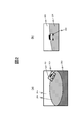
- FIG. 2 is a diagram showing a distortion correction process of a photographed image by the image correction unit 101.
- FIG. 2A is an example of a fish-eye image obtained by photographing with the camera 20 installed on the right side mirror of the host vehicle.
- the left part corresponds to the front, that is, the front direction of the host vehicle
- the right part corresponds to the rear, that is, the rear direction of the host vehicle.
- the road surface 204 is reflected in the center of the image
- the background 205 such as the sky
- the body 203 of the own vehicle is reflected in the lower part of the image.
- the other vehicle 202 is reflected.
- the image correction unit 101 sets, for example, an area including another vehicle 202 as the correction target area 201 for the fish-eye image as shown in FIG. Perform correction processing.
- FIG. 2B is an example of a corrected image obtained by performing distortion correction processing on the correction target area 201 of FIG.
- the other vehicle 202, the road surface 204, and the background 205 are corrected so as to be seen as being equivalent to an actual space map.
- the image correction unit 101 may set an arbitrary area in the captured image as the correction target area. As shown in FIG. Alternatively, a plurality of correction target areas may be set in the captured image, and distortion correction processing may be performed on each of the correction target areas. Furthermore, when performing vehicle detection using a portion with small distortion in the captured image, or when the camera 20 is a normal camera that is not a fisheye camera, the image correction unit 101 does not perform distortion correction processing. May be. In this case, the image processing apparatus 10 may not include the image correction unit 101.
- the priority direction selection unit 102 sets a priority direction that is a direction in which another vehicle, which is a detection target, should be detected preferentially based on the traveling state of the host vehicle. In order to determine the traveling state of the host vehicle, a signal indicating the traveling mode of the host vehicle is input to the priority direction selection unit 102.
- FIG. 3 is a diagram illustrating an example of a setting table used when the priority direction selection unit 102 sets the priority direction.
- the traveling mode of the host vehicle includes forward, backward, and parking assistance.
- different priority directions are shown for the general road and the expressway.
- the priority direction selection unit 102 obtains a signal indicating the travel mode of the host vehicle from a vehicle control CPU mounted on the host vehicle, thereby determining which of the host vehicle travel modes is, It can be determined whether the vehicle is traveling on a general road or an expressway.
- the priority direction selection unit 102 sets a priority direction according to the traveling mode and the traveling road of the host vehicle based on the setting table of FIG. For example, when the traveling mode of the host vehicle is forward, the priority direction selection unit 102 sets the rear of the host vehicle as the priority direction regardless of whether the traveling road is a general road or an expressway. That is, when the host vehicle is moving forward, the rear direction of the host vehicle is set as the priority direction so that other vehicles approaching from the rear of the host vehicle can be detected with priority regardless of the type of the traveling road.
- the priority direction selection unit 102 sets the rear direction of the host vehicle as the priority direction if the traveling road is a general road, and around the host vehicle if the traveling road is an expressway. Set all directions as preferred directions.
- the rear direction of the host vehicle is set as the priority direction so that other vehicles approaching from the rear of the host vehicle can be detected preferentially in the same way as when moving forward. To do. Normally, it is not expected that the host vehicle will retreat on the highway (except in the parking area), but in the unlikely event that such a situation occurs, the risk is high enough so that all directions around the host vehicle are prioritized. By setting as, other vehicles can be detected using the entire captured image.
- the priority direction selection unit 102 sets the front and rear of the host vehicle as the priority direction if the travel road is a general road, and the priority direction selection unit 102 All directions around the vehicle are set as priority directions. That is, when the host vehicle starts parallel parking using parking support on a general road, the front and rear of the host vehicle are preferentially detected so that other vehicles approaching from the front or rear of the host vehicle can be preferentially detected. Set as the preferred direction. Normally, it is not expected that the host vehicle will be parked on the highway (excluding the parking area), but in the unlikely event that such a situation occurs, the risk is sufficiently high. Is set as the priority direction, so that other vehicles can be detected using the entire captured image.
- the priority direction selection unit 102 sets a vehicle detection area for detecting another vehicle that is a detection target in the input image based on the setting result. At this time, the priority direction selection unit 102 sets the vehicle detection area in consideration of the priority direction set for the host vehicle. If the priority direction is not set, a predetermined area in the input image may be set as the vehicle detection area, or the entire input image may be set as the vehicle detection area.
- the vehicle detection unit 103 detects other vehicles that are detection objects existing around the host vehicle from the input image. Detect.
- the vehicle detection unit 103 detects other vehicles reflected in the vehicle detection region by executing a predetermined vehicle detection process on the portion set by the priority direction selection unit 102 in the input image as the vehicle detection region. To do.
- the vehicle detection unit 103 uses a detector to which a deep learning (Deep ⁇ Learning) method, which is a method of machine learning, is used to determine whether an image in the vehicle detection region has a characteristic as a vehicle. By performing the two-class detection for determining whether or not, another vehicle can be detected.
- a deep learning Deep ⁇ Learning
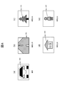
- FIG. 4 is a diagram illustrating an example of a learning image used when generating the detector of the vehicle detection unit 103.
- FIG. 4A is an example of a vehicle learning image
- FIGS. 4B to 4E are examples of non-vehicle learning images.
- the vehicle 300 is reflected, whereas in the learning images of FIGS. 4 (b) to 4 (e), subjects other than the vehicle are reflected.
- the road 301 is shown in the learning image of FIG. 4B
- the tree 302 is shown in the learning image of FIG. 4C
- the building 303 is shown in the learning image of FIG.
- the person 304 is reflected in the learning image of FIG.
- the non-vehicle learning image is not limited to the above example, and any subject other than the vehicle may be reflected.
- a plurality of images of a target object to be detected are input, image features representing the target object are extracted therefrom, and an unknown input image Is a processing method for automatically setting the parameters of the classifier so that the learned image features can be detected and identified.
- an unknown input image Is a processing method for automatically setting the parameters of the classifier so that the learned image features can be detected and identified.
- a feature parameter extraction method a feature extraction method using a neural network structure is known.
- a large number of input / output functions (activation functions) called neuron units that react only when matching the image features common to the input image group are combined for each small image area.
- classifier parameters are extracted for each layer of the neuron unit so that the object can be identified step by step while changing the position and image size of the object to be detected.
- a discriminator parameter capable of discriminating the entire object can be obtained.
- FIG. 5 is a diagram illustrating an example of a configuration of a deep learning type vehicle detector in the vehicle detection unit 103.
- the deep learning type vehicle detector used for detecting other vehicles in the vehicle detection unit 103 is configured by connecting a plurality of combinations of convolution layers and pooling layers, for example, three stages as shown in FIG.
- the first convolution layer 501 performs a convolution operation on image data corresponding to a portion in the vehicle detection area set by the priority direction selection unit 102 in the image input to the vehicle detection unit 103. Execute, and extract the first-stage feature map 509.
- the first pooling layer 502 aggregates the feature maps 509 extracted by the convolution layer 501 and reduces the data size.
- the second-stage convolution layer 503 performs a convolution operation on the data of the feature map 509 collected by the pooling layer 502 and extracts the second-stage feature map 510.
- the second-stage pooling layer 504 aggregates the feature maps 510 extracted by the convolution layer 503 to reduce the data size.
- the third-stage convolution layer 505 performs a convolution operation on the data of the feature map 510 aggregated by the pooling layer 504, and extracts the third-stage feature map 511.
- the third level pooling layer 506 aggregates the feature maps 511 extracted by the convolution layer 505 to reduce the data size.
- the overall coupling layer 507 identifies whether the input image is another vehicle by comparing the data of the feature map 511 aggregated by the pooling layer 506 with the classifier parameters acquired in advance by deep learning. Output the identification result. As a result, the vehicle detection unit 103 detects another vehicle to be detected from the input image.
- step number of the convolution layer and pooling layer which comprises a vehicle detector in the vehicle detection part 103 is not limited to this.
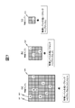
- FIG. 6 is a diagram illustrating an example of a feature map extracted for each convolution layer in the deep learning type vehicle detector illustrated in FIG. Note that the filter size and filter coefficient of the convolution layer and the aggregation coefficient of the pooling layer constituting the deep learning type vehicle detector can be designed arbitrarily, but here, as an example for explanation, each is as follows: Set.
- the size of the input image 600 to the vehicle detector is 32 ⁇ 32 pixels
- the filter coefficient of the first-stage convolutional layer 501 shown in FIG. 5 is indicated by reference numeral 601 in FIG.
- the filter is composed of 16 filter coefficients K1 to K16.
- the filter coefficients of the second-stage convolution layer 503 are configured by eight filter coefficients K17 to K24 as indicated by reference numeral 602 in FIG.
- the filter coefficients of the third-stage convolution layer 505 are composed of four filter coefficients K25 to K28 as indicated by reference numeral 603 in FIG.
- the aggregation coefficients of the first to third pooling layers 502, 504, and 506 shown in FIG. 5 are each set to 1/2.
- a convolution operation using the 16 filter coefficients K1 to K16 is performed on the input image 600 in the first-stage convolution layer 501.
- the first-stage feature map 509 data obtained by combining 16 types of aggregate blocks of 32 ⁇ 32 feature data is obtained.
- the data size is halved and 16 types of 16 ⁇ 16 feature data aggregate blocks are combined. Data is obtained.
- the feature map 509 is converted into a feature map 604 having a half data size.
- the second-stage feature map 510 data obtained by combining eight types of aggregate blocks of 16 ⁇ 16 feature data is obtained.
- the data size is halved, and 8 types of 8 ⁇ 8 feature data aggregate blocks are combined. Data is obtained.
- the feature map 510 is converted into a feature map 605 having a half data size.
- the third-stage convolution layer 505 a convolution operation using four filter coefficients K25 to K28 is performed on the feature map 605.
- the feature map 511 in the third stage data obtained by combining four types of aggregate blocks of 8 ⁇ 8 feature data is obtained.
- the data size is halved and four types of 4 ⁇ 4 feature data aggregate blocks are combined. Data is obtained.
- the feature map 511 is converted into a feature map 606 having a half data size.
- the vehicle detection unit 103 performs a convolution operation a plurality of times on the input image to detect other vehicles that are detection objects.
- the vehicle detection unit 103 outputs information indicating the presence or absence of an image of the other vehicle to the feature map verification unit 104 and the detection result correction unit 106 as the detection result of the other vehicle, for example, in the vehicle detection area set in the input image.
- the filter coefficient used in the convolution calculation of each convolution layer reacts strongly to image features such as vertical lines, horizontal lines, diagonal lines or curves important for image recognition, and extracts only the reacted image feature components. It is a filter numerical value group of image feature extraction set as described above.
- the filter coefficient is set so that the image feature components (the outline of the entire vehicle, the line of the hood, the line of the front window, the shade state of the vehicle body, etc.) constituting the vehicle shown in the input image can be extracted.
- design In filter design using machine learning, common image components included in the majority of input images can be acquired. For this reason, it is possible to automatically extract representative image feature components constituting the vehicle by learning a plurality of input images in which the vehicle is reflected during image learning in the preparation stage, and this can be used as a filter coefficient for convolution calculation. Use.
- the feature map verification unit 104 performs feature map verification to verify the probability that other vehicles are included in the input image, based on the feature maps obtained by the convolution calculation of the vehicle detection unit 103, respectively.
- the feature map verification unit 104 determines, for each of a plurality of blocks constituting the feature map, whether or not the feature of the other vehicle that is the detection target is shown, and compares the determination result with a pre-stored arrangement pattern. Thus, the feature map verification is performed.
- the feature map verification unit 104 performs feature map verification for verifying the probability that the other vehicle is included in the input image based on the arrangement in the feature map of the block where the feature of the other vehicle does not appear.
- FIG. 7 is a diagram illustrating an example of feature map verification performed by the feature map verification unit 104.
- the feature maps 509 to 511 obtained by the deep learning type vehicle detector described in FIGS. 5 and 6 are in the states shown in FIGS. 7 (a), 7 (b), and 7 (c), respectively.
- FIGS. 7 (a), 7 (b), and 7 (c) As an example, the operation of feature map verification will be described.
- each block represented by the block 601 indicated by hatching is a block (effective block) from which an effective feature level indicating the feature of another vehicle that is a detection target is obtained. is there.
- each block represented by the other block 602 is a block (invalid block) from which an effective feature level indicating the feature of another vehicle was not obtained.
- the invalid blocks for which no effective feature level appears are eight blocks indicated by A to H.
- each block indicated by hatching represents a valid block
- each other block represents an invalid block.
- the invalid blocks for which the effective feature level did not appear are three blocks indicated by I, J, and K.
- the invalid block for which no valid feature level has appeared is one block indicated by L.
- the feature map verification unit 104 stores in advance feature map arrangement patterns corresponding to the convolutional layers 501, 503, and 505 of FIG. 5 constituting the deep learning type vehicle detector in the vehicle detection unit 103.
- This arrangement map of the feature map represents a pattern of positions where valid blocks indicating features of other vehicles and invalid blocks that do not appear in the feature map.
- the feature map verification unit 104 compares each feature map with the arrangement pattern stored in advance, and based on the comparison result, another vehicle is included in the input image. Verify the likelihood of inclusion.
- the feature map obtained by the convolution calculation of the vehicle detection unit 103 is the presence of other vehicles. Is determined to have a high probability.
- the feature map verification unit 104 outputs a feature map verification signal with the signal value “TRUE”.
- the probability that the feature map obtained by the convolution calculation of the vehicle detection unit 103 indicates the presence of another vehicle. Is determined to be low.
- the feature map verification unit 104 outputs a feature map verification signal with the signal value “FALSE”.
- the feature map verification unit 104 preferably determines an arrangement pattern to be used for comparison of the above feature maps based on the priority direction set by the priority direction selection unit 102. This is because the vehicle detection area is set according to the priority direction, and if the priority direction is different, the image of the other vehicle reflected in the vehicle detection area may change, and the resulting feature map may also change. Because.
- the feature map verification unit 104 stores an arrangement pattern for each priority direction in advance, selects an arrangement pattern corresponding to the set priority direction, and compares it with the feature map. Thereby, even if a vehicle detection area changes according to a priority direction, feature map verification can be performed accurately.
- the time series verification unit 105 performs time series verification to verify the result of the feature map verification by the feature map verification unit 104 in time series.
- this time series verification based on the history of the value of the feature map verification signal output from the feature map verification unit 104, the result of the feature map verification performed by the feature map verification unit 104 is corrected as follows as necessary. To do.
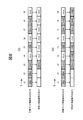
- FIG. 8 is a diagram illustrating an example of time-series verification performed by the time-series verification unit 105.
- the feature map verification unit 104 outputs a feature map verification signal of “TRUE” continuously in the time slots from time t1 to time t3.
- the time series verification unit 105 determines that there is a high probability that the feature map is another vehicle in the time slot at time t3 that satisfies the above condition, and generates a time series verification signal with the signal value “TRUE”. Output.
- the time series verification unit 105 corrects the result of the feature map verification performed by the feature map verification unit 104 and outputs a time series verification signal with the signal value “FALSE”.
- the feature map verification unit 104 outputs a “TRUE” feature map verification signal in each time slot at times t1 to t3, t5, and t7 to t8.
- the time-series verification unit 105 determines that the probability that the feature map is another vehicle is high in each of the time slots from time t3 to t5 and t7 to t9 that satisfy the above condition, and sets the signal value to “TRUE”.
- a time series verification signal is output.
- the feature map verification signal output from the feature map verification unit 104 is “FALSE”, which satisfies the above-described condition.
- the time series verification unit 105 corrects the result of the feature map verification performed by the feature map verification unit 104 and outputs a time series verification signal with the signal value “TRUE”.
- the time slot at time t6 that does not satisfy the condition, it is determined that the probability that the feature map is another vehicle is low, and a time-series verification signal with the signal value “FALSE” is output.
- time-series verification conditions in the time-series verification unit 105 are not limited to the above example. Any condition can be set as long as the result of the feature map verification by the feature map verification unit 104 can be verified in time series.
- the detection result correction unit 106 corrects the detection result of the other vehicle by the vehicle detection unit 103 based on the result of the time series verification by the time series verification unit 105. Specifically, for example, the detection result correcting unit 106 confirms the detection score indicating the certainty of the detection result of the other vehicle output from the vehicle detection unit 103 and the time series verification result output from the time series verification unit 105. The total score for the detection result of the other vehicle is calculated by adding the verification score indicating the likelihood. And the detection result of other vehicles is corrected by comparing the calculated total score with a predetermined threshold. In addition, you may correct the detection result of other vehicles by methods other than this.
- the detection result correcting unit 106 confirms that the other vehicle is approaching. A vehicle approach signal is output. Further, when a normal processing result cannot be obtained, for example, when a situation in which the detection result of the other vehicle by the vehicle detection unit 103 and the result of the time series verification by the time series verification unit 105 contradict each other for a certain period of time, It is determined that the reliability of the processing of the image processing apparatus 10 has decreased, and a detection FAIL signal is output.
- the image processing apparatus 10 includes a vehicle detection unit 103, a feature map verification unit 104, a time series verification unit 105, and a detection result correction unit 106.
- the vehicle detection unit 103 performs a convolution operation on an input image based on a captured image obtained by capturing with the camera 20, and detects an object, that is, another vehicle.
- the feature map verification unit 104 performs feature map verification to verify the probability that another vehicle is included in the input image, based on the feature map obtained by the convolution calculation of the vehicle detection unit 103.
- the time series verification unit 105 performs time series verification to verify the result of the feature map verification by the feature map verification unit 104 in time series.
- the detection result correction unit 106 corrects the detection result of the other vehicle by the vehicle detection unit 103 based on the result of the time series verification by the time series verification unit 105. Since it did in this way, the other vehicle which exists in the circumference
- the vehicle detection unit 103 performs a convolution operation on the input image a plurality of times.
- the feature map verification unit 104 performs feature map verification on each of a plurality of feature maps obtained by the plurality of convolution operations, for example, the feature maps 509, 510, and 511 shown in FIGS. Since it did in this way, according to the frequency
- the feature map verification unit 104 performs feature map verification by determining whether or not each of a plurality of blocks constituting the feature map indicates a feature of another vehicle that is a target object. Specifically, as described with reference to FIG. 7, the feature map verification unit 104 includes blocks determined to show the characteristics of other vehicles that are objects in the feature map, and other vehicles that are objects in the feature map. Feature map verification is performed based on the arrangement with blocks determined not to show features. Since it did in this way, feature map verification can be performed correctly and easily.
- the image processing apparatus 10 is further included in the host vehicle, and further includes a priority direction selection unit 102 that sets a direction in which another vehicle that is the target is to be detected preferentially based on the traveling state of the host vehicle. .
- the feature map verification unit 104 performs feature map verification based on a comparison result obtained by comparing the arrangement of the block with a previously stored arrangement pattern. At this time, the feature map verification unit 104 can determine an arrangement pattern to be used for comparison based on the direction set by the priority direction selection unit 102. In this way, the feature map verification can be performed accurately even if the vehicle detection area changes according to the set direction.
- FIG. 9 is a diagram showing an example of an external environment recognition apparatus according to the second embodiment of the present invention.
- the external environment recognition device 900 of this embodiment includes the image processing device 10 described in the first embodiment, a periphery recognition unit 901, a signal processing unit 902, and a driver notification unit 903.
- the external environment recognition device 900 is connected to the camera 20 mounted on the host vehicle, similarly to the image processing device 10, and also includes a control unit 911, a memory 912, a host vehicle control unit 913, an LED 914, and a speaker 915 mounted on the host vehicle.
- the display 916 and the car navigation device 917 are also connected. Note that the image processing apparatus 10 and other devices are connected to each other via a signal bus in the host vehicle.
- the camera 20 acquires a captured image around the host vehicle and outputs the captured image to the image processing apparatus 10 in the external environment recognition apparatus 900.
- the memory 912 temporarily holds a captured image acquired by the camera 20.
- the control unit 911 controls input / output of captured images between the camera 20 and the external environment recognition device 900 and input / output of vehicle control signals between the external environment recognition device 900 and the host vehicle control unit 913.
- the image processing apparatus 10 detects other vehicles existing around the host vehicle and outputs a vehicle approach signal based on the detection result to the surrounding recognition unit 901. Further, when it is difficult to detect other vehicles, a detection FAIL signal is output to the periphery recognition unit 901.
- the periphery recognition unit 901 performs a periphery recognition process for recognizing the surrounding environment of the host vehicle based on the signal. For example, the vicinity of the host vehicle and the surrounding space of the host vehicle are analyzed using the captured image of the camera 20 to recognize the presence or absence of other vehicles and pedestrians including motorcycles and bicycles, and hinders the driving and parking of the host vehicle. Recognize the presence or absence of obstacles. Further, when another vehicle or a pedestrian is approaching the own vehicle suddenly, this is detected and a collision with the own vehicle is predicted, or a collision between the own vehicle and an obstacle is predicted.
- the periphery recognition unit 901 outputs detection results and alarm information based on the execution result of the periphery recognition processing to the signal processing unit 902, and outputs notification information for the driver of the host vehicle to the driver notification unit 903 as necessary.
- the signal processing unit 902 generates a vehicle control signal for controlling the operation of the host vehicle based on the detection result and the alarm information output from the periphery recognition unit 901, and transmits the vehicle control signal to the host vehicle control unit 913.
- the own vehicle control unit 913 controls the operation of the own vehicle based on the vehicle control signal received from the signal processing unit 902 to stop the own vehicle in order to avoid a collision with another vehicle or a pedestrian, In order to avoid a collision with an obstacle, the traveling direction of the host vehicle is changed.
- the driver notification unit 903 Based on the notification information output from the periphery recognition unit 901, the driver notification unit 903 generates an alarm signal for warning the driver of the vehicle, and any of the LED 914, the speaker 915, the display 916, and the car navigation device 917 Send to.
- the LED 914, the speaker 915, the display 916, and the car navigation device 917 receive the warning signal received from the driver notification unit 903, the device performs a predetermined display and audio output based on the warning signal, thereby enabling the driver of the host vehicle.
- the presence of other vehicles approaching the host vehicle, pedestrians, obstacles, etc. is warned.
- the periphery recognition unit 901 performs the operation of the image processing apparatus 10. It is preferable to stop temporarily or continuously.
- the periphery recognition unit 901 can start or stop the operation of the image processing apparatus 10 by outputting an ON / OFF control signal to the image processing apparatus 10. Further, at this time, the notification information is output from the periphery recognition unit 901 to the driver notification unit 903, and based on this, the driver notification unit 903 generates an alarm signal and any one of the LED 914, the speaker 915, the display 916, and the car navigation device 917. To the driver of the own vehicle that the operation of the image processing apparatus 10 is stopped.
- the external environment recognition apparatus 900 includes the image processing apparatus 10. Further, the periphery recognition unit 901, the signal processing unit 902, and the driver notification unit 903 warn the driver of the host vehicle based on the detection result of the other vehicle corrected by the detection result correction unit 106 in the image processing apparatus 10. At least one of an alarm signal for performing and a vehicle control signal for controlling the operation of the host vehicle is output. Since it did in this way, the surrounding environment of the own vehicle can be recognized correctly.
- the target object detected from the captured image is another vehicle existing around the host vehicle.
- the target object is not limited to this, and another object may be the target object.
- the camera which acquires a picked-up image is not restricted to what was mounted in the vehicle.
Landscapes
- Engineering & Computer Science (AREA)
- Theoretical Computer Science (AREA)
- General Physics & Mathematics (AREA)
- Physics & Mathematics (AREA)
- Evolutionary Computation (AREA)
- Multimedia (AREA)
- Computer Vision & Pattern Recognition (AREA)
- Artificial Intelligence (AREA)
- Health & Medical Sciences (AREA)
- General Health & Medical Sciences (AREA)
- Life Sciences & Earth Sciences (AREA)
- Software Systems (AREA)
- Medical Informatics (AREA)
- Databases & Information Systems (AREA)
- Computing Systems (AREA)
- Biodiversity & Conservation Biology (AREA)
- Biomedical Technology (AREA)
- Molecular Biology (AREA)
- Data Mining & Analysis (AREA)
- Human Computer Interaction (AREA)
- Mechanical Engineering (AREA)
- Bioinformatics & Computational Biology (AREA)
- Evolutionary Biology (AREA)
- General Engineering & Computer Science (AREA)
- Bioinformatics & Cheminformatics (AREA)
- Traffic Control Systems (AREA)
- Image Analysis (AREA)
- Image Processing (AREA)
Abstract
L'invention concerne un dispositif de traitement d'image qui comprend une unité de détection d'objet pour effectuer une opération de convolution sur une image d'entrée sur la base d'une image capturée obtenue par imagerie avec un appareil photo et pour détecter un objet, une unité de vérification de carte de caractéristiques pour effectuer une vérification de carte de caractéristiques afin de vérifier la probabilité que l'objet soit inclus dans l'image d'entrée sur la base de la carte de caractéristiques obtenue par l'opération de convolution, une unité de vérification de série chronologique pour effectuer une vérification de série chronologique afin de vérifier le résultat de la vérification de carte de caractéristiques par l'unité de vérification de carte de caractéristiques en séries chronologiques, et une unité de correction de résultat de détection pour corriger le résultat de la détection de l'objet par l'unité de détection d'objet sur la base du résultat de la vérification de série chronologique par l'unité de vérification de série chronologique.
Priority Applications (2)
| Application Number | Priority Date | Filing Date | Title |
|---|---|---|---|
| EP17879882.3A EP3557524A4 (fr) | 2016-12-16 | 2017-12-13 | Dispositif de traitement d'image et dispositif de reconnaissance extérieure |
| US16/469,770 US11461595B2 (en) | 2016-12-16 | 2017-12-13 | Image processing apparatus and external environment recognition apparatus |
Applications Claiming Priority (2)
| Application Number | Priority Date | Filing Date | Title |
|---|---|---|---|
| JP2016244043A JP6888950B2 (ja) | 2016-12-16 | 2016-12-16 | 画像処理装置、外界認識装置 |
| JP2016-244043 | 2016-12-16 |
Publications (1)
| Publication Number | Publication Date |
|---|---|
| WO2018110605A1 true WO2018110605A1 (fr) | 2018-06-21 |
Family
ID=62559529
Family Applications (1)
| Application Number | Title | Priority Date | Filing Date |
|---|---|---|---|
| PCT/JP2017/044759 WO2018110605A1 (fr) | 2016-12-16 | 2017-12-13 | Dispositif de traitement d'image et dispositif de reconnaissance extérieure |
Country Status (4)
| Country | Link |
|---|---|
| US (1) | US11461595B2 (fr) |
| EP (1) | EP3557524A4 (fr) |
| JP (1) | JP6888950B2 (fr) |
| WO (1) | WO2018110605A1 (fr) |
Cited By (2)
| Publication number | Priority date | Publication date | Assignee | Title |
|---|---|---|---|---|
| JP2020071495A (ja) * | 2018-10-29 | 2020-05-07 | 日立オートモティブシステムズ株式会社 | 移動体挙動予測装置 |
| JP2020140591A (ja) * | 2019-03-01 | 2020-09-03 | KB−eye株式会社 | 管理サーバ、交通制御システム、交通制御方法および交通制御プログラム |
Families Citing this family (15)
| Publication number | Priority date | Publication date | Assignee | Title |
|---|---|---|---|---|
| JP6688277B2 (ja) * | 2017-12-27 | 2020-04-28 | 本田技研工業株式会社 | プログラム、学習処理方法、学習モデル、データ構造、学習装置、および物体認識装置 |
| US10969237B1 (en) * | 2018-03-23 | 2021-04-06 | Apple Inc. | Distributed collection and verification of map information |
| JP7028729B2 (ja) * | 2018-06-22 | 2022-03-02 | 株式会社 日立産業制御ソリューションズ | 物体追跡装置、物体追跡システム、および物体追跡方法 |
| JP7010780B2 (ja) * | 2018-07-10 | 2022-01-26 | Kddi株式会社 | 物体領域抽出装置及び物体領域抽出方法 |
| US10824947B2 (en) * | 2019-01-31 | 2020-11-03 | StradVision, Inc. | Learning method for supporting safer autonomous driving without danger of accident by estimating motions of surrounding objects through fusion of information from multiple sources, learning device, testing method and testing device using the same |
| JP7006635B2 (ja) * | 2019-02-28 | 2022-01-24 | 株式会社豊田中央研究所 | 制御装置、移動体、および学習方法 |
| JP6820489B2 (ja) * | 2019-06-13 | 2021-01-27 | 富士通クライアントコンピューティング株式会社 | 画像処理装置、および、画像処理プログラム |
| JP7145830B2 (ja) * | 2019-09-12 | 2022-10-03 | Kddi株式会社 | 符号化パラメータ特徴量を利用した対象識別方法、装置及びプログラム |
| CN111186379B (zh) * | 2020-01-21 | 2021-12-03 | 武汉大学 | 一种基于深度学习的汽车盲区危险物报警方法 |
| JP7396115B2 (ja) | 2020-02-26 | 2023-12-12 | 富士通株式会社 | テンプレート画像更新プログラム、テンプレート画像更新方法、及びテンプレート画像更新装置 |
| US20210356953A1 (en) * | 2020-05-18 | 2021-11-18 | At&T Intellectual Property I, L.P. | Deviation detection for uncrewed vehicle navigation paths |
| JP7244562B2 (ja) * | 2021-03-23 | 2023-03-22 | 本田技研工業株式会社 | 移動体の制御装置及び制御方法並びに車両 |
| JP7467402B2 (ja) | 2021-09-24 | 2024-04-15 | キヤノン株式会社 | 画像処理システム、移動装置、画像処理方法、およびコンピュータプログラム |
| CN115512306B (zh) * | 2022-11-15 | 2023-04-25 | 成都睿瞳科技有限责任公司 | 基于图像处理来预警电梯内暴力事件的方法 |
| CN116311361B (zh) * | 2023-03-02 | 2023-09-15 | 北京化工大学 | 一种基于像素级标注的危险源室内工作人员定位方法 |
Citations (3)
| Publication number | Priority date | Publication date | Assignee | Title |
|---|---|---|---|---|
| JP2001357396A (ja) * | 2000-06-16 | 2001-12-26 | Matsushita Electric Ind Co Ltd | 画像処理装置および画像認識装置 |
| JP2014067407A (ja) | 2012-09-24 | 2014-04-17 | Ricoh Co Ltd | 道路路面の可走行領域の検知方法及び検知装置 |
| JP2016153775A (ja) * | 2015-02-16 | 2016-08-25 | パナソニックIpマネジメント株式会社 | 物体検出装置および物体検出方法 |
Family Cites Families (9)
| Publication number | Priority date | Publication date | Assignee | Title |
|---|---|---|---|---|
| EP1056064B1 (fr) * | 1999-05-28 | 2007-12-12 | Nippon Telegraph and Telephone Corporation | Procédé et dispositif de vitesse des véhicules avec un système de traitement d'images |
| EP1356431A2 (fr) * | 2000-12-05 | 2003-10-29 | YEDA RESEARCH AND DEVELOPMENT Co. LTD. | Appareil et procede permettant d'aligner des sequences d'images sans chevauchement spatial ou temporel |
| JP4357935B2 (ja) * | 2003-11-14 | 2009-11-04 | 株式会社東芝 | 情報処理装置およびサインデータ入力プログラム |
| CN101398890B (zh) * | 2004-08-03 | 2010-12-08 | 松下电器产业株式会社 | 人物判定装置 |
| US8001062B1 (en) * | 2007-12-07 | 2011-08-16 | Google Inc. | Supervised learning using multi-scale features from time series events and scale space decompositions |
| KR101716646B1 (ko) * | 2013-01-10 | 2017-03-15 | 한국전자통신연구원 | 국부이진패턴을 이용한 객체 검출 인식 방법 및 장치 |
| KR20150108701A (ko) * | 2014-03-18 | 2015-09-30 | 삼성전자주식회사 | 의료 영상 내 해부학적 요소 시각화 시스템 및 방법 |
| US10061023B2 (en) | 2015-02-16 | 2018-08-28 | Panasonic Intellectual Property Management Co., Ltd. | Object detection apparatus and method |
| US20170124409A1 (en) * | 2015-11-04 | 2017-05-04 | Nec Laboratories America, Inc. | Cascaded neural network with scale dependent pooling for object detection |
-
2016
- 2016-12-16 JP JP2016244043A patent/JP6888950B2/ja active Active
-
2017
- 2017-12-13 WO PCT/JP2017/044759 patent/WO2018110605A1/fr active Search and Examination
- 2017-12-13 EP EP17879882.3A patent/EP3557524A4/fr active Pending
- 2017-12-13 US US16/469,770 patent/US11461595B2/en active Active
Patent Citations (3)
| Publication number | Priority date | Publication date | Assignee | Title |
|---|---|---|---|---|
| JP2001357396A (ja) * | 2000-06-16 | 2001-12-26 | Matsushita Electric Ind Co Ltd | 画像処理装置および画像認識装置 |
| JP2014067407A (ja) | 2012-09-24 | 2014-04-17 | Ricoh Co Ltd | 道路路面の可走行領域の検知方法及び検知装置 |
| JP2016153775A (ja) * | 2015-02-16 | 2016-08-25 | パナソニックIpマネジメント株式会社 | 物体検出装置および物体検出方法 |
Non-Patent Citations (2)
| Title |
|---|
| FUKUI, HIROSHI ET AL.: "Research trends for detecting pedestrian using Deep Learning", IEICE TECHNICAL REPORT, vol. 116, no. 366, 8 December 2016 (2016-12-08), pages 37 - 46, XP009515067 * |
| NINOMIYA, YOSHIKI: "The Present Condition and the Future Prospective of the Image Recognition Technology for Smart Vehicles", INFORMATION PROCESSING SOCIETY OF JAPAN, vol. 51, no. 12, 15 December 2010 (2010-12-15), pages 1569 - 1574, XP009515165 * |
Cited By (5)
| Publication number | Priority date | Publication date | Assignee | Title |
|---|---|---|---|---|
| JP2020071495A (ja) * | 2018-10-29 | 2020-05-07 | 日立オートモティブシステムズ株式会社 | 移動体挙動予測装置 |
| WO2020090419A1 (fr) * | 2018-10-29 | 2020-05-07 | 日立オートモティブシステムズ株式会社 | Dispositif de prédiction de comportement de corps mobile |
| JP7203563B2 (ja) | 2018-10-29 | 2023-01-13 | 日立Astemo株式会社 | 移動体挙動予測装置 |
| US11978345B2 (en) | 2018-10-29 | 2024-05-07 | Hitachi Astemo, Ltd. | Moving object behavior prediction device |
| JP2020140591A (ja) * | 2019-03-01 | 2020-09-03 | KB−eye株式会社 | 管理サーバ、交通制御システム、交通制御方法および交通制御プログラム |
Also Published As
| Publication number | Publication date |
|---|---|
| US11461595B2 (en) | 2022-10-04 |
| US20190370609A1 (en) | 2019-12-05 |
| EP3557524A4 (fr) | 2020-08-12 |
| JP2018097766A (ja) | 2018-06-21 |
| EP3557524A1 (fr) | 2019-10-23 |
| JP6888950B2 (ja) | 2021-06-18 |
Similar Documents
| Publication | Publication Date | Title |
|---|---|---|
| WO2018110605A1 (fr) | Dispositif de traitement d'image et dispositif de reconnaissance extérieure | |
| CN109478324B (zh) | 图像处理装置、外界识别装置 | |
| WO2018092265A1 (fr) | Dispositif et procédé d'aide à la conduite | |
| JP2005309797A (ja) | 歩行者警報装置 | |
| CN117994763A (zh) | 用于机动车辆的视觉系统和方法 | |
| US20180204462A1 (en) | Device and method for start assistance for a motor vehicle | |
| JP2016530639A (ja) | 奥行分解された画像データからのオブジェクトを認識するための方法ならびに装置 | |
| JP2008189148A (ja) | 走行状態検知装置 | |
| WO2017208601A1 (fr) | Dispositif de traitement d'image et dispositif de reconnaissance externe | |
| JP2014146267A (ja) | 歩行者検出装置、運転支援装置 | |
| KR20140104516A (ko) | 차선 인식 방법 및 장치 | |
| JP2017167608A (ja) | 物体認識装置、物体認識方法及び物体認識プログラム | |
| JP6891082B2 (ja) | 物体距離検出装置 | |
| JP2005309660A (ja) | 車両用右左折支援装置 | |
| US9881233B2 (en) | Image recognition apparatus | |
| KR101759270B1 (ko) | 차량 후보 검출 장치 및 그 방법 | |
| US20190188500A1 (en) | Apparatus for monitoring object in low light environment and monitoring method thereof | |
| JPWO2020129517A1 (ja) | 画像処理装置 | |
| WO2023095397A1 (fr) | Dispositif d'aide à la conduite, procédé d'aide à la conduite | |
| JP7005762B2 (ja) | カメラ装置の標識認識方法及び標識認識装置 | |
| KR20150092974A (ko) | 주변 차선 인식을 통한 차선 변경 차량 인식 장치 및 방법 | |
| KR101982091B1 (ko) | 서라운드 뷰 모니터링 시스템 | |
| KR102322815B1 (ko) | 카메라 기반의 도로이벤트 점유차로 검출 장치 및 그 방법 | |
| JP7145227B2 (ja) | 標識認識装置 | |
| US20170015245A1 (en) | Vehicle warning system and method of same |
Legal Events
| Date | Code | Title | Description |
|---|---|---|---|
| DPE1 | Request for preliminary examination filed after expiration of 19th month from priority date (pct application filed from 20040101) | ||
| 121 | Ep: the epo has been informed by wipo that ep was designated in this application |
Ref document number: 17879882 Country of ref document: EP Kind code of ref document: A1 |
|
| NENP | Non-entry into the national phase |
Ref country code: DE |
|
| ENP | Entry into the national phase |
Ref document number: 2017879882 Country of ref document: EP Effective date: 20190716 |