WO2018110174A1 - Electric furnace - Google Patents
Electric furnace Download PDFInfo
- Publication number
- WO2018110174A1 WO2018110174A1 PCT/JP2017/040600 JP2017040600W WO2018110174A1 WO 2018110174 A1 WO2018110174 A1 WO 2018110174A1 JP 2017040600 W JP2017040600 W JP 2017040600W WO 2018110174 A1 WO2018110174 A1 WO 2018110174A1
- Authority
- WO
- WIPO (PCT)
- Prior art keywords
- slag
- furnace
- molten
- furnace body
- molten slag
- Prior art date
Links
Images


Classifications
-
- F—MECHANICAL ENGINEERING; LIGHTING; HEATING; WEAPONS; BLASTING
- F27—FURNACES; KILNS; OVENS; RETORTS
- F27B—FURNACES, KILNS, OVENS, OR RETORTS IN GENERAL; OPEN SINTERING OR LIKE APPARATUS
- F27B3/00—Hearth-type furnaces, e.g. of reverberatory type; Tank furnaces
- F27B3/10—Details, accessories, or equipment peculiar to hearth-type furnaces
- F27B3/18—Arrangements of devices for charging
- F27B3/183—Charging of arc furnaces vertically through the roof, e.g. in three points
-
- F—MECHANICAL ENGINEERING; LIGHTING; HEATING; WEAPONS; BLASTING
- F27—FURNACES; KILNS; OVENS; RETORTS
- F27B—FURNACES, KILNS, OVENS, OR RETORTS IN GENERAL; OPEN SINTERING OR LIKE APPARATUS
- F27B3/00—Hearth-type furnaces, e.g. of reverberatory type; Tank furnaces
- F27B3/10—Details, accessories, or equipment peculiar to hearth-type furnaces
- F27B3/105—Slag chamber
-
- C—CHEMISTRY; METALLURGY
- C21—METALLURGY OF IRON
- C21C—PROCESSING OF PIG-IRON, e.g. REFINING, MANUFACTURE OF WROUGHT-IRON OR STEEL; TREATMENT IN MOLTEN STATE OF FERROUS ALLOYS
- C21C5/00—Manufacture of carbon-steel, e.g. plain mild steel, medium carbon steel or cast steel or stainless steel
- C21C5/28—Manufacture of steel in the converter
-
- C—CHEMISTRY; METALLURGY
- C21—METALLURGY OF IRON
- C21C—PROCESSING OF PIG-IRON, e.g. REFINING, MANUFACTURE OF WROUGHT-IRON OR STEEL; TREATMENT IN MOLTEN STATE OF FERROUS ALLOYS
- C21C5/00—Manufacture of carbon-steel, e.g. plain mild steel, medium carbon steel or cast steel or stainless steel
- C21C5/52—Manufacture of steel in electric furnaces
- C21C5/527—Charging of the electric furnace
-
- C—CHEMISTRY; METALLURGY
- C22—METALLURGY; FERROUS OR NON-FERROUS ALLOYS; TREATMENT OF ALLOYS OR NON-FERROUS METALS
- C22B—PRODUCTION AND REFINING OF METALS; PRETREATMENT OF RAW MATERIALS
- C22B7/00—Working up raw materials other than ores, e.g. scrap, to produce non-ferrous metals and compounds thereof; Methods of a general interest or applied to the winning of more than two metals
- C22B7/04—Working-up slag
-
- F—MECHANICAL ENGINEERING; LIGHTING; HEATING; WEAPONS; BLASTING
- F27—FURNACES; KILNS; OVENS; RETORTS
- F27B—FURNACES, KILNS, OVENS, OR RETORTS IN GENERAL; OPEN SINTERING OR LIKE APPARATUS
- F27B3/00—Hearth-type furnaces, e.g. of reverberatory type; Tank furnaces
- F27B3/04—Hearth-type furnaces, e.g. of reverberatory type; Tank furnaces of multiple-hearth type; of multiple-chamber type; Combinations of hearth-type furnaces
-
- F—MECHANICAL ENGINEERING; LIGHTING; HEATING; WEAPONS; BLASTING
- F27—FURNACES; KILNS; OVENS; RETORTS
- F27B—FURNACES, KILNS, OVENS, OR RETORTS IN GENERAL; OPEN SINTERING OR LIKE APPARATUS
- F27B3/00—Hearth-type furnaces, e.g. of reverberatory type; Tank furnaces
- F27B3/06—Hearth-type furnaces, e.g. of reverberatory type; Tank furnaces with movable working chambers or hearths, e.g. tiltable, oscillating or describing a composed movement
- F27B3/065—Hearth-type furnaces, e.g. of reverberatory type; Tank furnaces with movable working chambers or hearths, e.g. tiltable, oscillating or describing a composed movement tiltable
-
- F—MECHANICAL ENGINEERING; LIGHTING; HEATING; WEAPONS; BLASTING
- F27—FURNACES; KILNS; OVENS; RETORTS
- F27B—FURNACES, KILNS, OVENS, OR RETORTS IN GENERAL; OPEN SINTERING OR LIKE APPARATUS
- F27B3/00—Hearth-type furnaces, e.g. of reverberatory type; Tank furnaces
- F27B3/08—Hearth-type furnaces, e.g. of reverberatory type; Tank furnaces heated electrically, with or without any other source of heat
- F27B3/085—Arc furnaces
-
- F—MECHANICAL ENGINEERING; LIGHTING; HEATING; WEAPONS; BLASTING
- F27—FURNACES; KILNS; OVENS; RETORTS
- F27B—FURNACES, KILNS, OVENS, OR RETORTS IN GENERAL; OPEN SINTERING OR LIKE APPARATUS
- F27B3/00—Hearth-type furnaces, e.g. of reverberatory type; Tank furnaces
- F27B3/10—Details, accessories, or equipment peculiar to hearth-type furnaces
- F27B3/18—Arrangements of devices for charging
- F27B3/183—Charging of arc furnaces vertically through the roof, e.g. in three points
- F27B3/186—Charging in a vertical chamber adjacent to the melting chamber
-
- F—MECHANICAL ENGINEERING; LIGHTING; HEATING; WEAPONS; BLASTING
- F27—FURNACES; KILNS; OVENS; RETORTS
- F27B—FURNACES, KILNS, OVENS, OR RETORTS IN GENERAL; OPEN SINTERING OR LIKE APPARATUS
- F27B3/00—Hearth-type furnaces, e.g. of reverberatory type; Tank furnaces
- F27B3/10—Details, accessories, or equipment peculiar to hearth-type furnaces
- F27B3/12—Working chambers or casings; Supports therefor
- F27B2003/125—Hearths
-
- Y—GENERAL TAGGING OF NEW TECHNOLOGICAL DEVELOPMENTS; GENERAL TAGGING OF CROSS-SECTIONAL TECHNOLOGIES SPANNING OVER SEVERAL SECTIONS OF THE IPC; TECHNICAL SUBJECTS COVERED BY FORMER USPC CROSS-REFERENCE ART COLLECTIONS [XRACs] AND DIGESTS
- Y02—TECHNOLOGIES OR APPLICATIONS FOR MITIGATION OR ADAPTATION AGAINST CLIMATE CHANGE
- Y02P—CLIMATE CHANGE MITIGATION TECHNOLOGIES IN THE PRODUCTION OR PROCESSING OF GOODS
- Y02P10/00—Technologies related to metal processing
- Y02P10/20—Recycling
Definitions
- the present invention relates to an electric furnace used in a process in which molten slag produced in a steelmaking process is temporarily held in a molten state in a slag holding furnace and then injected into the electric furnace for reduction.
- Patent Document 1 steel slag is added to the molten steel in the melting furnace, heat and reducing material are added to transform the steel slag, and Fe, Mn, and P in the slag are transferred to the molten metal.
- a slag treatment method is disclosed, which includes a first step of obtaining Mn and P, and second and third steps of oxidizing Mn and P in the molten metal and sequentially transferring them to a metamorphic slag and sequentially taking out high Mn slag and high P slag. Yes.
- Patent Document 2 steel slag with an iron oxide content of more than 5 wt% is introduced into a steel bath with a carbon content of less than 1.5 wt%, and then the steel bath is carbonized by introducing carbon or a carbon carrier to contain the carbon.
- a method is disclosed in which a steel bath with a rate of greater than 2.0 wt% is obtained and thereafter the oxide in the steel slag is reduced.
- the carbon content of the steel bath is reduced before slag is charged.
- Non-Patent Document 1 discloses a result of a steel slag powder, a carbonaceous material powder, and a slag modifier powder charged in an electric furnace and subjected to a slag reduction test.
- Patent Document 3 in order to melt and reform steelmaking slag having low fluidity at low temperatures, the slag surface layer is mechanically added before and after the modifier is added to or sprayed on the low fluidity steelmaking slag contained in the container.
- a method is disclosed in which, after stirring, the mixed layer of slag and modifier is heated and melted using a heating burner, and the resulting molten slag is discharged from the container and solidified.
- Patent Document 4 high-temperature molten slag having fluidity is temporarily held in a slag holding furnace, and the molten slag layer is formed as a buffer zone on the molten iron layer in the electric furnace, and then the slag is held in the molten slag layer. It is described that molten slag is injected from the furnace.
- Patent Document 4 Since the structure of Patent Document 4 uses an electric furnace, the reduction reaction is dominated by the reaction between iron (FeO) and carbon (C) in the slag rather than the reaction between slag and molten iron. Therefore, even if the C concentration in the molten iron is as low as about 1.5% by mass, it is possible to perform slag reduction treatment without carburizing, which is excellent in that work efficiency can be improved. .
- Patent Document 4 does not directly put molten slag into the electric furnace, but temporarily holds it in a slag holding furnace arranged adjacent to the electric furnace, and buffers the molten slag layer on the molten iron layer in the electric furnace. Since the molten slag is gradually injected while adjusting the injection amount after forming as a band, it is also excellent in that slag forming at the time of slag injection can be suppressed.
- Non-Patent Document 1 a solidified cold steelmaking slag pulverized product is treated, and the method described in Patent Document 3 also treats steelmaking slag having low temperature and low fluidity.
- Patent Document 3 in order to perform the reduction treatment of slag, it is necessary to heat and melt the slag, and there has been a problem that the energy unit becomes high.
- Patent Document 4 even when an electric furnace having a slag holding furnace is used as in Patent Document 4 and the molten slag layer is formed as a buffer zone, the molten slag layer in the electric furnace may be disturbed depending on the injection amount and injection speed of the molten slag. As a result, the molten iron layer in the lower layer is in contact with the molten slag immediately after pouring, and slag forming may occur. Further, in Patent Document 4, when adjusting the slag injection amount from the slag holding furnace so that the molten slag layer is not disturbed, it is necessary to reduce the slag injection amount and the injection speed. .
- the holding furnace injects slag by tilting the furnace body, it is difficult to finely adjust the slag injection speed depending on the size of the holding furnace. Therefore, even if the injection speed is set to be small, the slag injection speed fluctuates, so that the injection speed temporarily increases and slag forming may occur.
- the present invention has been made in view of the above problems, and can prevent the molten slag immediately after being injected from the slag holding furnace and the molten iron layer in the electric furnace from being vigorously mixed to generate large slag forming.
- the purpose is to provide a furnace.
- the gist of the present invention is as follows.
- One embodiment of the present invention is an electric furnace having a furnace body having an electrode, and a slag holding furnace capable of holding the molten slag in a molten state and injecting the molten slag into the furnace body by tilting.
- the furnace body includes a cylindrical furnace wall, a furnace lid provided at an upper end of the furnace wall, a lower end provided at a lower end of the furnace wall, and a height relative to a deepest part of the deep bottom part.
- the inlet has an overlap with the shallow bottom in plan view, and the area ratio in plan view of the shallow bottom with respect to the furnace bottom is 5% or more and 40% or less.
- the furnace wall has a main body having a circular cross-sectional shape perpendicular to the height direction, and a projecting portion projecting in the radial direction of the main body.
- the shallow bottom portion may be provided at a lower end of the overhang portion, and the slag inlet may be provided at an upper end of the overhang portion.
- the furnace wall has a main body having a circular cross-sectional shape perpendicular to the height direction, and the shallow bottom portion is provided at a lower end of the main body. Also good.
- the electric furnace is provided in the furnace lid or both the furnace lid and the furnace wall, and the reducing material is placed in the furnace. There may be provided a reducing material charging port for charging to.
- the electric furnace described above since it is possible to prevent the molten slag immediately after being injected from the slag holding furnace from contacting the molten iron layer in the electric furnace, the molten slag and the molten iron layer can be prevented from being vigorously mixed. . Therefore, it can prevent that a molten slag layer and a molten iron layer react rapidly, and produce
- FIG. 4 is a transverse sectional view taken along the line II of the furnace body shown in FIGS. 2 and 3. It is a cross-sectional view of the furnace body at a height of 150 mm from the furnace bottom, and shows only a shallow bottom part and a deep bottom part. It is a longitudinal cross-sectional view which shows the slag holding furnace (injection attitude
- FIG. 6 is a transverse cross-sectional view taken along the line II-II of the electric furnace shown in FIG. It is a figure which shows the simulation result of the slag injection
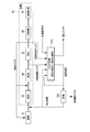
- hot metal is produced using a blast furnace in the iron making process (S1), and pig iron is refined into steel using a converter or the like in the steel making process (S2).
- the steelmaking process (S2) includes desulfurization, dephosphorization, and decarburization processes for removing sulfur, phosphorus, carbon, etc. in the hot metal, and adjustment of components by removing gases such as hydrogen and sulfur remaining in the molten steel.
- the secondary refining process (S6) to perform and the continuous casting process (S7) which casts molten steel with a continuous casting machine are included.
- dephosphorization (S4) and decarburization (S5) are mainly performed in the converter.
- hot metal is refined using a flux mainly composed of calcium oxide.
- oxygen, blown into the converter oxidizes C, Si, P, Mn and the like in the hot metal, and the oxide is combined with calcium oxide and generated as slag.
- slag (desulfurization slag, dephosphorization slag, decarburization slag) having different components is generated.
- steel making slag includes desulfurization slag, dephosphorization slag, and decarburization slag.
- Steelmaking slag in a molten state at high temperature is referred to as molten slag.
- desulfurized slag, dephosphorized slag, and decarburized slag in molten state are respectively melted desulfurized slag, molten dephosphorized slag, and molten decarburized slag. Called.
- the molten slag generated in the steel making step (S2) is transported from the converter to the electric furnace in a molten state, and continuously reduced and reformed in the electric furnace, Valuables such as Fe and P in the molten slag are recovered in the molten iron layer below the molten slag layer.
- a reduction process of oxides such as Fe and P in the molten slag, a process of separating granular iron (iron) from the slag, a process of adjusting the basicity of the slag, and the like are performed.
- the recovered high-phosphorus molten iron is subjected to dephosphorization treatment (S11), and P in the molten iron is oxidized and transferred to the slag, so that the high-phosphorus molten iron is separated into the high phosphoric acid slag and the molten iron.
- High phosphoric acid slag can be recycled as phosphoric acid fertilizer or phosphoric acid raw material.
- the molten iron is recycled to the steel making process (S2) and is put into a converter or the like.
- the outline of the slag treatment process has been explained.
- the molten dephosphorized slag is at a lower temperature than the molten decarburized slag, but contains a large amount of granular iron and phosphoric acid.
- recovery efficiency of valuable elements (Fe, P, etc.) by this process becomes high by melt-modifying molten dephosphorization slag not by oxidation treatment but by reduction treatment. Therefore, in the following description, an example in which molten dephosphorization slag is mainly used as the molten slag to be processed will be described.
- the molten slag of the present invention is not limited to molten dephosphorization slag, and any steelmaking slag generated in the steelmaking process such as molten desulfurization slag and molten decarburization slag can be used.
- the electric furnace 100 used for the slag treatment process (S10) of the slag treatment process will be described.
- the electric furnace 100 is a furnace in which the molten iron layer 6 and the molten slag layer 5 are formed inside in S10.
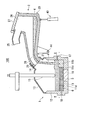
- the electric furnace 100 includes a furnace body 1 and a slag holding furnace 2 (slag holding container) disposed obliquely above the furnace body 1.
- a means for introducing the molten slag 4 into the slag holding furnace 2 is a slag pot 3, and the slag pot 3 reciprocates between a converter (not shown) and the slag holding furnace 2.
- the molten slag 4 discharged from the converter is put into the slag pan 3.
- the slag pan 3 is charged into the slag holding furnace 2 after conveying the molten slag 4 from the converter to the slag holding furnace 2.
- the slag holding furnace 2 can also store and hold the molten slag 4 in a molten state, and the held molten slag 4 can be continuously or intermittently injected into the furnace body 1 by tilting.
- the molten slag 4 held in the slag holding furnace 2 does not need to be in a completely molten state. Even if a part is solidified, the whole may have fluidity that can be injected into the furnace body 1.
- the furnace body 1 is a reduction-type electric furnace that melts, reduces, and reforms the molten slag 4 by using a reducing material such as a carbonaceous material and a secondary material such as a modifying material, and has, for example, a furnace tilting mechanism.
- a reducing material such as a carbonaceous material
- a secondary material such as a modifying material
- an example of a stationary DC electric furnace will be described.
- the furnace body 1 includes a furnace wall 12, a furnace lid 13 provided at the upper end of the furnace wall 12, and a furnace provided at the lower end of the furnace wall 12. And a bottom 11.
- a refractory is lined on the inner surfaces of the furnace bottom 11, the furnace wall 12, and the furnace lid 13.
- a slag inlet 14 is formed on one side of the furnace lid 13. The slag inlet 14 is connected to the spout part 21 of the slag holding furnace 2.
- the furnace body 1 is sealed except for the slag inlet 14 and can keep the inside of the furnace warm.
- an upper electrode 15 and a furnace bottom electrode 16 are arranged vertically opposite to each other.
- a DC power source to the upper electrode 15 and the furnace bottom electrode 16 to generate an arc discharge between the upper electrode 15 and the furnace bottom electrode 16 to generate an arc discharge between the upper electrode 15 and the furnace bottom electrode 16
- energy necessary for reducing the molten slag 4 is supplied.
- the furnace lid 13 can be provided with a reducing material inlet 31a.
- the reducing material inlet 31 a is connected to the raw material supply devices 31 and 32.
- the furnace wall 12 can be provided with a reducing material charging port 33a.
- a raw material supply device 33 is provided at the reducing material charging port 33a.
- the reducing material inlets 31a and 33a are parts for supplying auxiliary materials such as a reducing material and a modifying material necessary for the reduction treatment of the molten slag 4.
- FIG. 2 illustrates the structure in which the reducing material charging port is provided in both the furnace wall 12 and the furnace lid 13, the reducing material charging port may be provided only in the furnace lid 13.
- the reducing material fine powdery carbon materials such as coke powder, anthracite coal powder, and graphite powder are used.
- the modifier mainly adjusts the concentration of SiO 2 or Al 2 O 3 in the slag, and silica sand, fly ash, waste refractory powder and the like can be used.
- the reducing material is also a suppressing means when slag forming occurs.
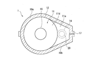
- the furnace bottom 11 has a deep bottom portion 11d and a shallow bottom portion 11a whose bottom is shallower than the deep bottom portion 11d.
- the shallow bottom part 11a is installed on the assumption that it has a part exposed from the surface of the molten iron layer 6 during the slag treatment process.
- hot metal or molten steel may be charged into the electric furnace 100 together with the molten slag 4, and hot metal is generated as the slag is reduced, so the height of the molten iron layer 6 increases. To do.
- the hot water outlet 18 for discharging the molten iron is opened to reduce the height of the molten iron layer 6, so that the shallow bottom portion 11a is exposed from the molten iron layer 6 in the period after the decrease, In this state, it is assumed that the molten slag 4 to be reduced next is injected into the electric furnace 100. However, the molten slag 4 cannot be injected unless the shallow bottom portion 11a is exposed from the molten iron layer 6. If the height of the molten iron layer 6 is lower than a certain level on the shallow bottom portion 11a, the injected molten slag 4 is not injected.
- the object of the present invention can be achieved.
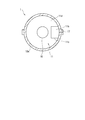
- a structure of the furnace body 1 as shown in FIGS. 4A and 4B, a structure having a protruding portion 10b (first embodiment) and a structure having no protruding portion 10b as shown in FIG. Embodiment) can be adopted.
- the first embodiment will be described as an example.
- the furnace body 1 includes a cylindrical main body portion 10a having a ring-shaped cross section perpendicular to the height direction, and a main body portion.
- the shallow bottom portion 11a is a portion raised as a part of the furnace bottom 11 during the slag treatment process, assuming that it is higher than the layer thickness of the molten iron layer 6, for example, FIG. 2 and FIG. As shown in FIG. 2, the bottom 10 is formed in a stepped shape by the overhanging portion 10b.
- the shallow bottom part 11a is a refractory like the inner surface of the other part of the furnace bottom 11. As shown in FIG. 4A, the shallow bottom portion 11a overlaps the slag inlet 14 in plan view.
- the existence region of the shallow bottom portion 11a and the existence region of the slag inlet 14 partially or entirely overlap.
- the molten slag 4 injected from the slag holding furnace 2 into the furnace flows in through the spout 29. Since the spout 29 is in the region of the slag inlet 14, the molten slag flowing from the spout will drop toward the shallow bottom portion 11a. That is, the shallow bottom portion 11a includes the dropping position of the molten slag 4 flowing down from the slag inlet 14. Thereby, when the molten slag 4 is injected into the furnace body 1, the molten slag 4 is injected toward the shallow bottom portion 11a. In the overhanging portion 10 b, a slag inlet 14 is formed in the furnace lid 13.
- the shallow bottom portion 11a is formed by the furnace bottom 11 being shallowed by one step at the overhanging portion 10b, but the shallow bottom portion 11a is not limited to this shape.
- the shallow bottom portion 11a may be formed by shallowing the furnace bottom 11 over two or more stages, or the furnace bottom 11 may be shallow by forming a continuous slope in the overhanging portion 10b.
- the shallow bottom portion 11a may be formed.
- the shallow bottom portion 11a does not necessarily have a horizontal plane as shown in FIG. As long as it can be assumed that the shallow bottom portion 11a is exposed from the molten iron layer 6 during the slag treatment process below the slag inlet 14, the entire shallow bottom portion 11a may be stepped or sloped.
- the shallow bottom portion 11a has a horizontal surface, it is preferable in that the area ratio in a plan view of the shallow bottom portion 11a with respect to the furnace bottom 11 can be secured 5% or more without reducing the furnace volume more than necessary.
- the shallow bottom portion 11a is a region where the height H of the deep bottom portion 11d with respect to the deepest portion is 150 mm or more and 500 mm or less. This is because if the height is 150 mm or more, an effect of relaxing the situation where the newly charged molten slag 4 is vigorously mixed with the original molten iron layer 6 can be expected. Moreover, the reason why the height of the deep bottom portion 11d with respect to the deepest portion is 500 mm or less is that there is no point in making it over 500 mm. As shown in FIG.
- the area ratio in plan view of the shallow bottom part 11a against the bottom of the furnace 11 is preferably 5% or more and 40% or less.
- the area ratio is 5% or more, the ratio of the molten slag layer 5 that can enjoy the mixing relaxation effect is ensured, and intense formation of the slag as a whole can be suppressed.
- the area ratio is more than 40%, the forming generation suppressing effect is hardly increased, but the molten iron capacity as the molten iron layer 6 and the interfacial area between the molten iron layer 6 and the molten slag layer 5 are reduced. There is a concern that the reduction efficiency is reduced. Further, if it exceeds 40%, the shallow bottom portion 11a is included in the high current density region of the furnace bottom 11, and therefore the shallow bottom portion 11a is easily consumed.
- the shallow bottom portion 11a in the present invention "height H to the deepest portion of the deep portion 11d is 150mm or more, 500 mm or less in the region" because it defines the boundary of S 1 and S 2 are deepest portion of the deep portion 11d
- the height H with respect to the position is 150 mm.
- the shallow bottom portion 11 a is exposed from the molten iron layer 6 while submerged in the molten slag layer 5, but may be exposed from the molten slag layer 5.
- the molten slag 4 injected from the slag inlet 14 collides with the surface of the shallow bottom portion 11 a, then flows down the surface of the shallow bottom portion 11 a and flows into the molten slag layer 5. Since the kinetic energy is reduced by the collision of the molten slag 4 with the surface of the shallow bottom portion 11a, the molten slag 4 does not mix vigorously with the molten iron layer 6. Therefore, the rapid reaction between the molten slag 4 and the molten iron is also suppressed, and slag forming is suppressed.
- the furnace wall 12 can be provided with a tap outlet 17 for discharging reduced slag and a tap outlet 18 for discharging molten iron.
- the taphole 17 is formed at a position corresponding to the molten slag layer 5, specifically at a position higher than the upper surface of the shallow bottom portion 11 a.
- the hot water outlet 18 is formed at a position corresponding to the molten iron layer 6, specifically at a position lower than the upper surface of the shallow bottom portion 11 a.
- the slag holding furnace 2 is a heat-resistant container that holds the molten slag 4 and injects it into the furnace body 1.
- the slag holding furnace 2 can adjust the injection amount of the molten slag 4 into the furnace body 1 and is also an exhaust path for exhaust gas generated in the furnace body 1.
- the slag holding furnace 2 includes a furnace body 20 that stores and holds the molten slag 4, and a spout portion 21 that injects the molten slag 4 in the furnace body 20 into the furnace body 1.
- the furnace body 20 is a sealed container and has an internal space for storing the molten slag 4.
- a gas discharge port 25 and a slag input port 26 are formed in the furnace body 20.
- the gas discharge port 25 is an exhaust port that discharges the exhaust gas of the furnace body 1 via the slag holding furnace 2, and is connected to an intake device such as a dust collector (not shown).
- the atmosphere in the slag holding furnace 2 is maintained at a negative pressure by the intake device.
- the slag inlet 26 is an opening for introducing the molten slag 4 from the upper slag pot 3 into the furnace body 20.
- An open / close type holding furnace lid 27 is installed at the slag inlet 26, and the holding furnace lid 27 is opened when the molten slag 4 is charged. When the molten slag 4 is not charged, the holding furnace lid 27 is closed and the slag charging port 26 is closed, so that the outside air is prevented from entering the furnace body 20 and the interior of the furnace body 20 is kept warm.
- the spout 21 is a cylinder provided on the furnace body 1 side of the furnace body 20.
- the inner space of the spout 21 is a slag injection path 28 for injecting the molten slag 4 from the furnace body 20 into the furnace body 1, and the opening formed at the tip of the spout 21 is the spout 29.
- the slag injection path 28 is narrower in the vertical direction and the furnace width direction (perpendicular to the paper surface of FIG. 2) than the internal space of the furnace body 20, and is curved downward as it goes forward in the injection direction.
- the internal space of the furnace body 20 is also gradually narrowed toward the spout portion 21 side.
- the spout 21 of the slag holding furnace 2 is connected to the slag inlet 14 of the furnace lid 13 of the furnace body 1.
- the inner diameter of the slag inlet 14 of the furnace body 1 is made larger than the outer diameter of the pouring spout 21, and the tip of the spout 21 is inserted into the slag inlet 14, with a gap between the two. There is a slight gap.
- the structure for connecting the spout portion 21 and the slag injection port 14 is not limited to the structure shown in FIG. 2, and the two are hermetically connected using a bellows or the like, or the gap between them is filled with a filler. Various changes are possible.
- the slag holding furnace 2 becomes an exhaust path for the exhaust gas generated in the furnace body 1. .
- the exhaust gas containing CO, H 2, etc. generated by the reduction treatment in the furnace body 1 passes through the slag inlet 14 of the furnace body 1 and the spout portion 21 of the slag holding furnace 2 and flows through the slag holding furnace 2. It flows into the furnace body 20.
- the inside of the slag holding furnace 2 is maintained at a negative pressure, even if outside air enters through a gap between the connecting portions of the furnace body 1 and the slag holding furnace 2, the exhaust gas in the furnace body 1 is exposed from the gap to the outside. Does not leak. The outside air that has entered through the gap is sucked to the slag holding furnace 2 side. Further, the exhaust gas flowing into the slag holding furnace 2 proceeds into the furnace body 20 and is discharged from the gas discharge port 25, reaches a dust collector (not shown), and is processed.
- a tilting device 40 is provided on the lower side of the furnace body 20 of the slag holding furnace 2.
- the tilting device 40 is a device that tilts the slag holding furnace 2 toward the pouring part 21 and injects the molten slag 4 in the furnace body 20 into the furnace body 1 from the pouring part 21.
- the tilting device 40 can tilt the slag holding furnace 2 about the tilting shaft 44 between the holding posture (FIG. 2) and the pouring posture (FIG. 3).
- the holding posture is a posture when the slag holding furnace 2 holds the molten slag 4 in the furnace body 20 without injecting the molten slag 4 into the furnace body 1.
- the pouring posture is a posture when the slag holding furnace 2 is tilted toward the spout portion 21 and the molten slag 4 in the furnace body 20 is poured into the furnace body 1.
- the slag holding furnace 2 When changing the slag holding furnace 2 from the holding posture to the pouring posture, the slag holding furnace 2 is tilted toward the furnace body 1 around the tilting shaft 44. Thereby, as shown in FIG. 3, since the position of the spout part 21 becomes relatively low with respect to the furnace body 20, the molten slag 4 held in the furnace body 20 is moved to the spout part 21 side. It flows from the spout 29 through the slag injection path 28 and is poured into the furnace body 1. At this time, the amount of molten slag 4 injected can be adjusted by adjusting the tilt angle of the slag holding furnace 2.
- the electric furnace 100 according to the present embodiment can inject the molten slag 4 into the furnace body 1 intermittently or adjust the injection amount by tilting the slag holding furnace 2 using the tilting device 40. .
- an injection amount is used by using the tilting device 40 so that the injected molten slag 4 does not abruptly react with the molten iron in the furnace body 1 and overflow from the furnace body 1. It is preferable to inject molten slag 4 intermittently while appropriately adjusting (that is, adjusting the tilt angle of slag holding furnace 2).
- the molten slag 4 may be in a forming state in the furnace body 1, and overflow may occur.
- the tilt angle of the slag holding furnace 2 is decreased by the tilting device 40, and the injection of the molten slag 4 is temporarily stopped, or the injection amount is reduced to calm the reaction in the furnace body 1. It is preferable to do.
- the amount of molten slag 4 injected per unit time by the slag holding furnace 2 is determined according to the reduction treatment capacity of the furnace body 1.
- the reduction processing capacity depends on the amount of power supplied to the furnace body 1 per unit time, for example, the amount of power applied to the upper electrode 15 and the furnace bottom electrode 16 of the furnace body 1. Therefore, the injection amount of the molten slag 4 per unit time may be determined based on the power consumption necessary for the reduction treatment of the molten slag 4 and the actual amount of power applied to the upper electrode 15 and the furnace bottom electrode 16.
- a method of intermittently injecting molten slag 4 from the slag holding furnace 2 into the furnace body a method of injecting the molten slag 4 while repeating injection and interruption of the molten slag 4 as appropriate, or a predetermined time interval in the slag holding furnace 2.
- the molten slag 4 is injected intermittently, it is preferable to confirm beforehand by experiments or the like that the total amount of the molten slag 4 injected at one time is an amount that does not cause overflow due to slag forming.
- molten iron such as molten iron transported from the blast furnace is accommodated in the furnace body 1 as a molten iron layer 6 in advance as seed hot water.
- the C concentration of molten iron is usually 1.5 to 4.5% by mass.
- an amount of molten slag 4 corresponding to the reduction processing capacity of the furnace body 1 (for example, the amount of power supplied per unit time to the furnace body 1) is shown in FIG. 3, the slag holding furnace 2 is injected into the furnace body 1.
- the molten slag 4 injected into the furnace body 1 forms a molten slag layer 5 on the molten iron layer 6.
- the injected molten slag 4 falls toward the shallow bottom portion 11a, it does not come into direct contact with the molten iron layer 6. Therefore, the presence of the shallow bottom portion 11a can effectively prevent slag forming.
- auxiliary materials such as a reducing material (carbon material) and a reforming material are continuously fed into the molten slag layer 5 in the furnace body 1 through the material supply devices 31, 32 and 33.
- the temperature of the molten iron layer 6 is controlled to be, for example, 1400 to 1550 ° C.
- the temperature of the molten slag layer 5 is, for example, 1500 to 1650 ° C. This temperature control can be performed by adjusting the supply amount of the molten slag 4 or adjusting the power supply amount without changing the molten slag supply amount.
- the reduction reaction of the molten slag 4 in the molten slag layer 5 proceeds in the furnace body 1 using the arc heat between the upper electrode 15 and the furnace bottom electrode 16 as an energy source.
- oxides (FeO, P 2 O 5, etc.) contained in the molten slag 4 are reduced by carbon of the carbonaceous material in the molten slag layer 5 to generate Fe and P, and the generated Fe , P moves from the molten slag layer 5 to the molten iron layer 6.
- the surplus carbon material C is suspended in the molten slag layer 5 and finally dissolved in the molten iron.
- FeO contained in the injected molten slag 4 preferentially reacts with C of the carbonaceous material in the molten slag layer 5 rather than C contained in the molten iron in the molten iron layer 6 (FeO + C ⁇ Fe + CO ⁇ ).
- the carbon material C that has been charged does not move to the molten iron layer 6 but is suspended in the molten slag layer 5, so that the reduction reaction of FeO + C ⁇ Fe + CO proceeds preferentially in the molten slag layer 5 and is generated.
- the reduced iron (Fe) moves to the molten iron layer 6.
- the reaction between FeO and C in the molten slag layer 5 is more dominant than the reaction between FeO in the molten slag layer 5 and C in the molten iron layer 6. is there. Therefore, when the molten slag 4 is injected into the furnace body 1, the molten slag layer 5 on the molten iron layer 6 becomes a buffer zone for the reaction between the injected molten slag 4 and the molten iron in the molten iron layer 6. Coupled with the effect of providing the bottom 11a, the rapid reaction between the molten slag 4 and the molten iron can be suppressed.
- the FeO concentration of the injected molten slag 4 can be reduced, and the injected molten slag 4 and the molten iron of the molten iron layer 6 can be reduced. Direct contact can be suppressed. Therefore, when the molten slag 4 is injected from the slag holding furnace 2 into the furnace body 1, slag forming due to a rapid reaction between the molten slag 4 and the molten iron can be suppressed, and overflow can be avoided.
- the oxide contained in the molten slag 4 injected into the molten slag layer 5 in the furnace body 1 is reduced, and Fe and P are recovered from the molten slag 4 to the molten iron layer 6.
- FeO and P 2 O 5 of the molten slag 4 are reduced, and the slag component is modified. Therefore, if the reduction process proceeds after the injection of the molten slag 4, the components of the molten slag layer 5 are gradually reformed from the molten slag 4 (steel slag) to reduced slag (high quality slag equivalent to blast furnace slag). Go.
- the molten slag layer 5 modified to reduced slag becomes a buffer zone having a lower FeO concentration.
- the molten slag layer 5 may be disturbed by the molten slag 4.
- the molten slag 4 immediately after injection is provided. Does not contact the molten iron layer 6. Accordingly, slag forming due to a rapid reaction of the molten slag 4 immediately after the injection with the molten iron layer 6 is also prevented.
- slag foaming can be sedated by defoaming and reducing foaming slag by introducing carbonaceous powder from the reducing material inlets 31a and 33a.
- the layer thickness of the molten slag layer 5 is preferably 100 to 600 mm, more preferably 100 to 800 mm, from the viewpoint of developing a function as a buffer zone.
- the spout 17 is opened and the reduced slag of the molten slag layer 5 is discharged.
- the hot water outlet 18 is opened and the molten iron (for example, high P molten iron) of the molten iron layer 6 is discharged
- the reduced slag is intermittently discharged and recovered from the outlet 18 of the furnace body 1 and the molten iron is intermittently discharged and recovered.
- the reduction process of the molten slag 4 can be continued without interruption.
- high temperature exhaust gas containing CO, H 2, etc. is generated by reducing the oxide of the molten slag 4 using the carbonaceous material C.
- CO gas is generated by the reaction of FeO + C ⁇ Fe + CO ⁇ .
- the exhaust gas flows into the slag holding furnace 2 through the slag inlet 14 of the furnace body 1 and is discharged outside through the slag holding furnace 2 as an exhaust path.
- the atmosphere in the furnace body 1 is mainly composed of CO gas generated by a reduction reaction and H 2 generated from a carbonaceous material (reducing material). Maintained in a reducing atmosphere. Therefore, the oxidation reaction on the surface of the molten slag layer 5 can be prevented.
- the furnace body 1 does not have the overhanging portion 10 b.
- the furnace body 1 has a main body portion 10a having an annular cross section.
- the shallow bottom portion 11b is a region in which the furnace bottom 11 is partially raised in a region overlapping with the slag inlet 14 of the main body portion 10a in plan view.
- the shallow bottom portion 11b is formed by, for example, a box-shaped step 11c arranged in contact with the inside of the furnace wall 12.
- the surface of the step 11c is made of a refractory material in the same manner as the inner surface of the bottom 11 of the other part.
- the second embodiment has a general furnace shape, and is advantageous in that the shallow bottom portion 11b can be formed by attaching the step 11c later even if the existing electric furnace does not have the shallow bottom portion 11b. .
- the molten slag 4 injected from the slag inlet 14 is slag.
- the molten slag layer 5 flows down below the inlet 14.
- the molten slag 4 immediately after injection reacts rapidly with the molten iron layer 6 and bumps. This can prevent slag forming from occurring.
- the second embodiment of the present invention described above has an advantage over the first embodiment in that the shallow bottom portion 11b can be formed later in an existing electric furnace.
- the first embodiment can make the shallow bottom portion 11 a wider, a molten iron layer is formed in a portion where the molten slag layer 5 is disturbed by the injected molten slag 4 and a lower layer of the molten slag layer 5. It is possible to increase the distance from the portion where 6 is present, and to increase the effect of preventing slag forming.
- the position of the shallow bottom portion 11b is closer to the center of the furnace body 1 than in the first embodiment.
- first embodiment and the second embodiment of the present invention have different advantages, they can be appropriately selected and implemented according to, for example, operation conditions and the current state of equipment. Further, the present invention is not limited to these embodiments, and other embodiments that are obvious to those skilled in the art can be adopted by describing these embodiments.
- Furnace volume 13.8 m 3 Furnace bottom area (S 1 + S 2 ): 7.5 m 2 Furnace slag viscosity: 0.25 Pa ⁇ s Injection slag viscosity: 1.0 Pa ⁇ s Molten iron viscosity: 0.006 Pa ⁇ s Shallow bottom height (H): 250 mm Shallow bottom area (S 2 ): 1.1 m 2 Amount of seed bath: 1.4m 3 Injection slag flow width: 500mm Slag injection speed: 1t / min, 5t / min, 10t / min, 20t / min
- Example A is an example in which the slag injection rate is 10 t / min and there is a shallow bottom portion 11a
- Comparative Example A is an example in which the slag injection rate is 1 t / min and there is no shallow bottom portion 11a
- Example B has a slag injection rate of 5 t.
- Example in which there is no shallow bottom portion 11a at / min Comparative Example C shows an example in which the slag injection rate is 10 t / min and no shallow bottom portion 11a
- Comparative Example D shows an example in which the slag injection rate is 20 t / min and there is no shallow bottom portion 11a.
- FIG. 7 Example A is an example in which the slag injection rate is 10 t / min and there is a shallow bottom portion 11a
- Comparative Example A is an example in which the slag injection rate is 1 t / min and there is no shallow bottom portion 11a
- Example B has a slag injection rate of 5 t.
- the charging amount of the carbon material powder was increased to 3.5 kg / min, and about 25 minutes after the latest molten slag 4 was charged, 20 kg of molten slag 4 was injected at a time.
- CO gas with a flow rate of 250 Nm 3 / h or more was generated immediately after the injection of the molten slag 4, and thereafter the flow rate gradually decreased.
- FIG. 8 in the electric furnace 100 without the shallow bottom portion 11a, CO gas was generated immediately after the injection of the molten slag 4, suggesting the possibility of slag forming.
- carbon powder is supplied at 45 kg / min through the reducing material inlets 31 a and 33 a while continuously supplying 30 MW of power to the upper electrode 15 and the furnace bottom electrode 16. Feeded at speed. Furthermore, through the reducing material inlet 31a, silica sand was supplied at a supply rate of 67 kg / min and waste alumina refractory powder was supplied at a supply rate of 8 kg / min.
- restoration process the time until injection
- the operation pattern was the same except that the injection cycle and the injection amount per one time were different.
- the injection period and the injection amount per time were as in Example 1, Example 4, and Comparative Example 1 (injection period 5 minutes, injection amount 4.0 t to 4.3 t per injection), Example 2 and Comparative Example 2. (Injection cycle 10 minutes, injection amount 8.0t to 8.5t per injection) and Example 3 and Comparative Example 3 (injection cycle 15 minutes, injection amount 12t to 13t per injection).
- composition of the molten slag 4 discharged from the converter to the slag pan 3 is as shown in Table 1 below.
- Example 3 Although the slag forming height rose to 600 mm at a time, when carbon material powder was blown in at 3 kg / min for 3 minutes from two side walls, it was calmed down to 300 mm. As a result, even in Example 3 in which the injection cycle was the longest and the injection amount per injection was large, the slag forming height could be suppressed to 300 mm.
- the furnace body 1 according to the first embodiment of the present invention can increase the amount of slag injection per time as compared with the conventional case by providing the shallow bottom portion 11a while suppressing the occurrence of slag forming. It can be said that it has become possible.
- Example 4 using the furnace body 1 according to the second embodiment, the slag forming height (160 mm) is similar to Example 1 (90 mm) using the furnace body 1 according to the first embodiment. Although it is slightly higher than that of Comparative Example 1 (1200 mm) under the same conditions, it is greatly reduced. As a result, CO gas generation was mild. Therefore, it was proved that the furnace body 1 according to the second embodiment also has a sufficient effect of suppressing slag forming by providing the shallow bottom portion 11b.
- Example 4 in the operation of 700 to 1000 charges was possible before the refractory on the surface of the shallow bottom portion 11a melted 50 mm.
- Example 4 in the operation of 200 to 300 charges, the refractory on the surface of the shallow bottom portion 11b was melted by 50 mm. Accordingly, it can be said that the furnace body 1 according to the first embodiment is proved to be more advantageous in terms of durability of the furnace bottom 11. As described above, the furnace body 1 according to the second embodiment has other advantages.
- an electric furnace that can prevent the molten slag immediately after being injected from the slag holding furnace and the molten iron layer in the electric furnace from being vigorously mixed to generate large slag forming.
- Furnace body 2 Slag holding furnace 3: Slag pan 4: Molten slag 5: Molten slag layer 6: Molten iron layer 10a: Main body part 10b: Overhang part 11: Furnace bottom 11a: Shallow bottom part 11c: Shallow bottom part 11c: Step 11d: Deep bottom 12: Furnace wall 13: Furnace lid 14: Slag inlet 15: Upper electrode 16: Furnace bottom electrode 17: Outlet 18: Outlet 20: Furnace body 21: Spout 25: Gas outlet 26 : Slag inlet 27: Holding furnace lid 28: Slag injection path 29: Spout 31: Raw material supply device 31a: Reducing material input port 33a: Reducing material input port 32: Raw material supply device 33: Raw material supply device 40: Tilt device 44 : Tilt axis 100: Electric furnace
Abstract
Description
本願は、2016年12月16日に、日本に出願された特願2016-244501号に基づき優先権を主張し、その内容をここに援用する。 The present invention relates to an electric furnace used in a process in which molten slag produced in a steelmaking process is temporarily held in a molten state in a slag holding furnace and then injected into the electric furnace for reduction.
This application claims priority based on Japanese Patent Application No. 2016-244501 filed in Japan on December 16, 2016, the contents of which are incorporated herein by reference.
非特許文献1には、電気炉内に製鋼スラグ粉、炭材粉およびスラグ改質材粉を装入し、スラグの還元試験を行った結果が開示されている。 In
Non-Patent
また、特許文献4では、溶融スラグ層がかく乱されないようにスラグ保持炉からのスラグ注入量を調整する場合、スラグ注入量および注入速度を下げる必要があるため、処理効率が下がるという問題があった。また、保持炉は炉体を傾動させることによりスラグを注入するため、保持炉の大きさによってはスラグ注入速度の微細な調整が困難である。そのため、注入速度を小さく設定したとしてもスラグ注入速度が変動することにより、一時的に注入速度が大きくなってしまい、スラグフォーミングが発生する虞があった。 Furthermore, even when an electric furnace having a slag holding furnace is used as in
Further, in
(1)本発明の一態様は、電極を有する炉体と、溶融スラグを溶融状態のまま保持するとともに傾動により前記溶融スラグを前記炉体に注入可能なスラグ保持炉と、を有する電気炉であって、前記炉体は、筒状の炉壁と、前記炉壁の上端に設けられた炉蓋と、前記炉壁の下端に設けられ、深底部と、前記深底部の最深部に対する高さが150mm以上、500mm以下の領域である浅底部と、を有する炉底と、前記炉蓋に設けられ、前記スラグ保持炉から前記溶融スラグが注入されるスラグ注入口と、を有し、前記スラグ注入口は前記浅底部と平面視で重なりを有し、前記炉底に対する前記浅底部の平面視における面積率が5%以上、40%以下である。
(2)上記(1)に記載された電気炉では、前記炉壁は、高さ方向に垂直な断面形状が円環形状の本体と、前記本体の径方向に張り出した張出部を有し、前記浅底部は前記張出部の下端に設けられ、前記スラグ注入口は前記張出部の上端に設けられてもよい。
(3)上記(1)に記載された電気炉では、前記炉壁は、高さ方向に垂直な断面形状が円環形状の本体を有し、前記浅底部は前記本体の下端に設けられてもよい。
(4)上記(1)~(3)に記載されたいずれか一項に記載された電気炉では、前記炉蓋、または前記炉蓋と前記炉壁の両方に設けられ、還元材を炉内に投入する還元材投入口を有してもよい。 That is, the gist of the present invention is as follows.
(1) One embodiment of the present invention is an electric furnace having a furnace body having an electrode, and a slag holding furnace capable of holding the molten slag in a molten state and injecting the molten slag into the furnace body by tilting. The furnace body includes a cylindrical furnace wall, a furnace lid provided at an upper end of the furnace wall, a lower end provided at a lower end of the furnace wall, and a height relative to a deepest part of the deep bottom part. A furnace bottom having a shallow bottom portion that is an area of 150 mm or more and 500 mm or less, and a slag inlet provided in the furnace lid and into which the molten slag is injected from the slag holding furnace, and the slag The inlet has an overlap with the shallow bottom in plan view, and the area ratio in plan view of the shallow bottom with respect to the furnace bottom is 5% or more and 40% or less.
(2) In the electric furnace described in the above (1), the furnace wall has a main body having a circular cross-sectional shape perpendicular to the height direction, and a projecting portion projecting in the radial direction of the main body. The shallow bottom portion may be provided at a lower end of the overhang portion, and the slag inlet may be provided at an upper end of the overhang portion.
(3) In the electric furnace described in the above (1), the furnace wall has a main body having a circular cross-sectional shape perpendicular to the height direction, and the shallow bottom portion is provided at a lower end of the main body. Also good.
(4) In the electric furnace described in any one of (1) to (3) above, the electric furnace is provided in the furnace lid or both the furnace lid and the furnace wall, and the reducing material is placed in the furnace. There may be provided a reducing material charging port for charging to.
まず、図1を参照して、本発明の実施形態に係る電気炉を使用したスラグ処理プロセスの概要を説明する。 [1. Overview of slag treatment process]
First, an outline of a slag treatment process using an electric furnace according to an embodiment of the present invention will be described with reference to FIG.
続いて、図2を参照して、上記スラグ処理プロセスのスラグ処理工程(S10)に用いられる電気炉100について説明する。
電気炉100はS10において、内部に溶鉄層6と溶融スラグ層5を形成する炉である。 [2. Slag treatment equipment configuration]
Then, with reference to FIG. 2, the
The
スラグ保持炉2へ溶融スラグ4を投入する手段はスラグ鍋3であり、スラグ鍋3は図示しない転炉とスラグ保持炉2との間を往復移動する。転炉から排出された溶融スラグ4はスラグ鍋3に投入される。スラグ鍋3は、転炉からスラグ保持炉2まで溶融スラグ4を搬送した後、スラグ保持炉2内に投入する。スラグ保持炉2は、溶融スラグ4を溶融状態のまま貯留して保持することもでき、当該保持した溶融スラグ4を傾動により炉体1に連続的または間欠的に注入可能である。 As shown in the enlarged portion of FIG. 2, the
A means for introducing the
引き続き図2、図3、図4A、及び図4Bを参照して、炉体1の構成について説明する。
図2、図3、図4A、及び図4Bに示すように、炉体1は、炉壁12と炉壁12の上端に設けられた炉蓋13と、炉壁12の下端に設けられた炉底11とを有する。炉底11、炉壁12、および炉蓋13のそれぞれの内面には、耐火物が内張されている。炉蓋13の一側にはスラグ注入口14が形成されている。スラグ注入口14は、スラグ保持炉2の注ぎ口部21に連結される。炉体1はスラグ注入口14を除いて密閉されており、炉内を保温できる。 [3. Configuration of furnace body 1]
The configuration of the
As shown in FIG. 2, FIG. 3, FIG. 4A, and FIG. 4B, the
浅底部11aは、スラグ処理工程中には、溶鉄層6の表面から露出した部分を有していることを想定して、設置されている。
スラグ処理中においては、溶融スラグ4と一緒に電気炉100に溶銑または溶鋼が装入されることがあるほか、スラグ還元に伴って溶銑が生成されるために、溶鉄層6の高さが上昇する。ある程度以上に溶鉄層が厚くなったら、溶鉄を排出する出湯口18を開けて溶鉄層6の高さを低下させるので、低下した後の期間には浅底部11aを溶鉄層6から露出させて、その状態で、次に還元処理する溶融スラグ4を電気炉100内へ注入することを、想定している。ただし、浅底部11aが溶鉄層6から露出してないと溶融スラグ4を注入できないわけではなく、溶鉄層6の高さが浅底部11aの上で、ある程度以上低ければ、注入された溶融スラグ4と溶鉄層6との激しい混合は抑制されるので、本発明の目的を達成できる。
炉体1の構造として、図4A、図4Bに示すように張出部10bを有する構造(第1の実施形態)と、図6に示すように張出部10bを有しない構造(第2の実施形態)を採用することができる。ここではまず第1の実施形態を例に説明を行う。
第1の実施形態では、図4A、図4Bの横断面図に示されるように、炉体1が、高さ方向に垂直な断面形状が円環形状の筒状の本体部10aと、本体部10aから径方向の外側に張り出した、張出部10bとを有する場合について説明する。
浅底部11aは、スラグ処理工程中には炉底11の一部として、溶鉄層6の層厚よりも上になることを想定して、嵩上げされた部分であり、例えば、図2および図3に示されるように、張出部10bで炉底11が階段状に浅くなることによって形成される。浅底部11aは、他の部分の炉底11の内面と同様に耐火物である。
図4Aに示すように、浅底部11aはスラグ注入口14と平面視で重なりを有している。換言すると、平面視において、浅底部11aの存在領域とスラグ注入口14の存在領域は、その一部または全部が重なっている。スラグ保持炉2から炉内に注入される溶融スラグ4は、注ぎ口29を経由して流入する。注ぎ口29はスラグ注入口14の領域内にあるので、注ぎ口から流入した溶融スラグは浅底部11aに向けて落下することになる。即ち、浅底部11aはスラグ注入口14から流下する溶融スラグ4の落下位置を含むことになる。これにより、溶融スラグ4が炉体1に注入される場合、溶融スラグ4は浅底部11aに向けて注入される。
張出部10bでは、炉蓋13にスラグ注入口14が形成される。 The furnace bottom 11 has a
The shallow
During the slag treatment, hot metal or molten steel may be charged into the
As a structure of the
In the first embodiment, as shown in the cross-sectional views of FIGS. 4A and 4B, the
The
As shown in FIG. 4A, the
In the overhanging
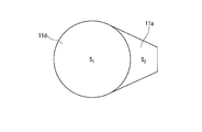
図4Bに示すように、深底部11dの平面視における面積をS1、浅底部11aの平面視における面積をS2とすると、炉底11に対する浅底部11aの平面視における面積率(S2/(S1+S2)×100)は5%以上、40%以下であるのが好ましい。面積率が5%以上あることで、混合緩和効果を享受できる溶融スラグ層5の比率が確保されて、スラグ全体としての激しいフォーミング生成を抑制することができる。面積率が40%超の場合、フォーミング生成の抑制効果が高まることが殆ど無い一方、溶鉄層6としての溶鉄収容量や、溶鉄層6と溶融スラグ層5との界面積が少なくなってしまうので、還元効率が低下する懸念が生じる。また、40%を超えると浅底部11aが炉底11の高電流密度領域に含まれるため、浅底部11aが消耗しやすくなるためである。
なお、本発明では浅底部11aを「深底部11dの最深部に対する高さHが150mm以上、500mm以下の領域」と定義しているため、S1とS2の境界は深底部11dの最深部に対する高さHが150mmの位置である。 As shown in FIG. 2, the
As shown in FIG. 4B, S 1 and the area in plan view of the
Incidentally, the
次に、図2および図3を参照して、本実施形態に係るスラグ処理プロセスで用いられる、スラグ保持炉2の構成について詳述する。 [4. Slag holding furnace configuration]
Next, with reference to FIG. 2 and FIG. 3, the structure of the
スラグ保持炉2は、溶融スラグ4を貯留・保持する炉本体20と、炉本体20内の溶融スラグ4を炉体1に注入する注ぎ口部21を備える。 As shown in FIG. 2, the
The
傾動装置40は、傾動軸44を中心としてスラグ保持炉2を保持姿勢(図2)と注入姿勢(図3)との間で、傾動させることが可能である。保持姿勢とは、図2に示すように、スラグ保持炉2が溶融スラグ4を炉体1に注入することなく、炉本体20内に保持するときの姿勢である。注入姿勢とは、図3に示すように、スラグ保持炉2が注ぎ口部21側に傾動して、炉本体20内の溶融スラグ4を炉体1内に注入するときの姿勢である。 The tilting
The tilting
引き続き図2および図3を参照して、上記構成の電気炉100を用いた溶融スラグ4の還元処理について説明する。
まず、還元処理の前に深底部11dの面積S1とHを決定し、決定した値に基づき、浅底部11aを形成する必要がある。
具体的には、溶鉄層6の最大体積(種湯と還元鉄を合計した体積)がS1×H未満となるようにS1とHを決定する。 [5. Method for reducing molten slag]
Next, with reference to FIG. 2 and FIG. 3, the reduction process of the
First, before the reduction treatment, it is necessary to determine the areas S 1 and H of the
Specifically, S 1 and H are determined so that the maximum volume of molten iron layer 6 (the total volume of seed hot water and reduced iron) is less than S 1 × H.
さらに、還元材(炭材)や改質材等の副原料も、原料供給装置31,32,33を通じて炉体1内の溶融スラグ層5に連続的に投入する。また、炉体1内では、溶鉄層6の温度が例えば1400~1550℃、溶融スラグ層5の温度が例えば1500~1650℃となるように制御される。この温度制御は、溶融スラグ4の供給量を調整することや、溶融スラグ供給量を変更せず電力供給量を調整することで実施できる。 Next, after supplying electric power to the
Further, auxiliary materials such as a reducing material (carbon material) and a reforming material are continuously fed into the
溶融スラグ層5の層厚は、緩衝帯としての機能を発現させるという観点から、100~600mmが好ましく、100~800mmがより好ましい。溶融スラグ層5の層厚が上限に近づいた場合は、出滓口17を開放して、溶融スラグ層5の還元スラグを排出する。また、溶鉄層6の界面が浅底部11aの上面に近づいた場合は、出湯口18を開放して、溶鉄層6の溶鉄(例えば高P溶銑)を排出する。このようにして、炉体1の出滓口17から還元スラグを、出湯口18から溶鉄を、間欠的に排出、回収する。これにより、炉体1内では、溶融スラグ4の還元処理を、中断することなく継続することができる。 Further, as the reduction treatment proceeds, Fe moves into the molten iron, and the layer thickness of the
The layer thickness of the
次に、本発明の第2の実施形態について図5および図6を参照して説明する。第2の実施形態は、上述した第1の実施形態と比べて炉体1の形状が相違するのみであり、その他の機能・構成は、第1の実施形態と実質的に同一であるので、詳細説明は省略する。 [6. Second Embodiment]
Next, a second embodiment of the present invention will be described with reference to FIGS. The second embodiment is different only in the shape of the
浅底部11bは、本体部10aのスラグ注入口14と平面視で重なりを有する領域で、炉底11が部分的に嵩上げされた部分である。浅底部11bは、例えば、炉壁12の内側に接して配置された箱型のステップ11cによって形成される。ステップ11cの表面は、他の部分の炉底11の内面と同様に耐火物で構成される。 As shown in FIGS. 5 and 6, in the second embodiment, the
The
まず、実操業に先立って浅底部11aの有無の影響を確かめるために、図2に示す電気炉100を仮定したコンピュータシミュレーションを行った。具体的な手順は以下の通りである。
まず汎用流体解析ソフトFLUENTを用いて、以下の条件の電気炉に溶融スラグ4を注入して、その挙動を炉の軸断面方向から観察した。
炉の容積:13.8m3
炉底面積(S1+S2):7.5m2
炉内スラグ粘度:0.25Pa・s
注入スラグ粘度:1.0Pa・s
溶鉄粘度:0.006Pa・s
浅底部の高さ(H):250mm
浅底部の面積(S2):1.1m2
種湯量:1.4m3
注入スラグ流の幅:500mm
スラグ注入速度:1t/min、5t/min、10t/min、20t/min (simulation)
First, in order to confirm the influence of the presence or absence of the
First, using general-purpose fluid analysis software FLUENT,
Furnace volume: 13.8 m 3
Furnace bottom area (S 1 + S 2 ): 7.5 m 2
Furnace slag viscosity: 0.25 Pa · s
Injection slag viscosity: 1.0 Pa · s
Molten iron viscosity: 0.006 Pa · s
Shallow bottom height (H): 250 mm
Shallow bottom area (S 2 ): 1.1 m 2
Amount of seed bath: 1.4m 3
Injection slag flow width: 500mm
Slag injection speed: 1t / min, 5t / min, 10t / min, 20t / min
図7に示すように、スラグ注入速度が1t/minの場合は、浅底部11aが無い比較例Aでも、注入された溶融スラグ4がほとんど溶鉄層6に達しておらず、注入された溶融スラグ4と溶鉄層6との反応は僅かしか認められなかった。
スラグ注入速度が5t/min、10t/min、20t/minの場合は、浅底部11aが無い場合に注入された溶融スラグ4が溶鉄層6に達して、一部は溶鉄層6中に突入し溶鉄中のCと反応する様が予見された。特に10t/min、20t/minでは、反応が激しく、溶鉄と溶融スラグ4とが混合して飛び散ることが分かった。
一方で、浅底部11aがある場合は、スラグ注入速度が10t/minでも、注入された溶融スラグ4がほとんど溶鉄層6とは反応せず、したがって溶鉄と溶融スラグ4との混合物が飛び散ることも無いと考えられた。
この結果から、浅底部11aを設けることにより、注入された溶融スラグ4が溶鉄層6と混合して、激しく反応することを防止できることが分かった。 The results are shown in FIG. In FIG. 7, Example A is an example in which the slag injection rate is 10 t / min and there is a
As shown in FIG. 7, when the slag injection speed is 1 t / min, even in Comparative Example A where there is no
When the slag injection speed is 5 t / min, 10 t / min, and 20 t / min, the
On the other hand, when there is the
From this result, it has been found that the provision of the
次に、図2に示す電気炉100において、浅底部11aがない構造を用いてスラグ注入試験を行い、COガス発生量を測定した。具体的な手順は以下の通りである。
まず、炉体1に溶鉄層6および溶融スラグ層5を予め形成した。炉体1の条件は浅底部11aがないこと以外はシミュレーションと同じである。 (Slag injection test: comparative example)
Next, in the
First, the
次に、炭材粉の投入量は変えずに操業を続け、最初の溶融スラグ4の投入から約20分後に溶融スラグ4を540kg一度に注入した。その結果、溶融スラグ4の注入直後に流量400Nm3/h以上のCOガスが発生し、その後は徐々に流量が低下した。
さらに、炭材粉の投入量は変えずに操業を続け、直近の溶融スラグ4の投入から約15分後に溶融スラグ4を800kg一度に注入した。その結果、溶融スラグ4の注入直後に流量500Nm3/h以上のCOガスが発生し、その後は徐々に流量が低下した。
その後、炭材粉の投入量を3.5kg/minに増加させ、直近の溶融スラグ4の投入から約25分後に溶融スラグ4を20kg一度に注入した。その結果、溶融スラグ4の注入直後に流量250Nm3/h以上のCOガスが発生し、その後は徐々に流量が低下した。
以上の結果を図8に示す。
図8に示すように、浅底部11aがない電気炉100においては、溶融スラグ4の注入直後にCOガスが発生しており、スラグフォーミングが生じている可能性が示唆された。 Next, after supplying 2.4 MW (240 V, 10 kA) to the
Next, the operation was continued without changing the input amount of the carbonaceous powder, and about 540 kg of
Further, the operation was continued without changing the input amount of the carbon powder, and 800 kg of
Thereafter, the charging amount of the carbon material powder was increased to 3.5 kg / min, and about 25 minutes after the latest
The above results are shown in FIG.
As shown in FIG. 8, in the
次に、図2に示す電気炉100において、浅底部11aがある構造を用いてスラグ注入試験を行い、COガス発生量を測定した。具体的な手順は以下の通りである。
炉体1に電力2.4MW(240V、10kA)を供給して連続稼働させた上で、炭材粉を投入せずに、溶融スラグ4を780kg一度に注入した。その他の条件は「スラグ注入試験:比較例」と同様とした。その結果、溶融スラグ4の注入直後はCOガスが発生せず、その後のCOガス発生量も流量で100Nm3/h以下であった。
以上の結果を図9に示す。
図9に示すように、浅底部11aがある電気炉100においては、溶融スラグ4の注入直後にCOガスが発生せず、浅底部11aがスラグフォーミングの発生を抑制していると考えられた。 (Slag injection test: Example)
Next, in the
After supplying 2.4 MW (240 V, 10 kA) to the
The above results are shown in FIG.
As shown in FIG. 9, in the
次に、浅底部がある場合とない場合とで、図10に示す操業パターンで電気炉を操業し、スラグフォーミングの有無を確認した。
まず、以下の条件の電気炉100を用意した。
炉の容積:13.8m3
炉底面積(S1+S2):7.5m2
スラグ組成:(T.Fe)0.8%、(CaO)33.1%、(SiO2)28.4%
溶鉄組成:[C]2.8%,[Si]0.18%,[P]0.33%
浅底部の高さ(H):250mm
浅底部の面積(S2):1.1m2
種湯量:1.3m3 (Actual operation test)
Next, the electric furnace was operated with the operation pattern shown in FIG. 10 with and without the shallow bottom, and the presence or absence of slag forming was confirmed.
First, an
Furnace volume: 13.8 m 3
Furnace bottom area (S 1 + S 2 ): 7.5 m 2
Slag composition: (T.Fe) 0.8%, (CaO) 33.1%, (SiO 2 ) 28.4%
Molten iron composition: [C] 2.8%, [Si] 0.18%, [P] 0.33%
Shallow bottom height (H): 250 mm
Shallow bottom area (S 2 ): 1.1 m 2
Amount of seed bath: 1.3m 3

結果の概要を表2に示す。 In each of the examples and comparative examples, as an index indicating the reaction state in the
A summary of the results is shown in Table 2.
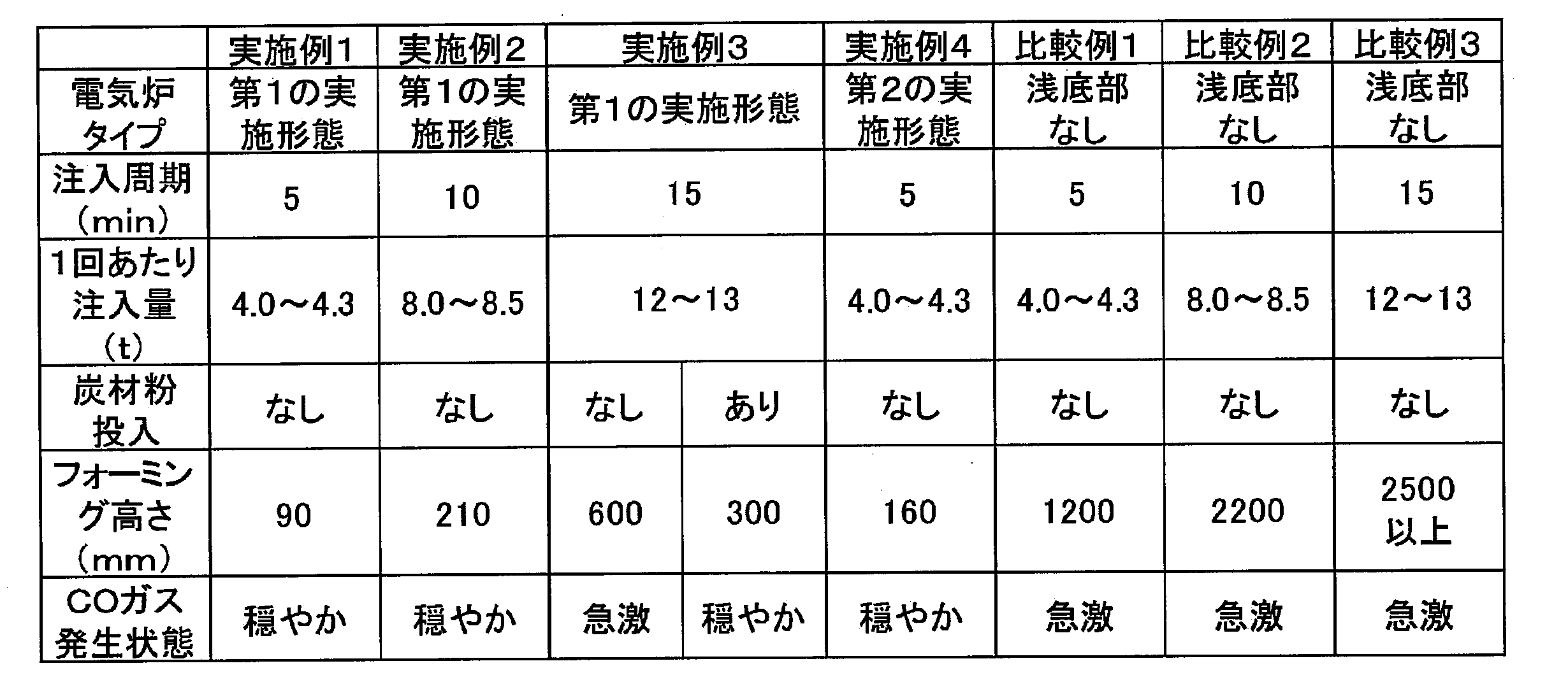
また、比較例1~3のいずれにおいても、炉体1においてCOガスが急激に発生した。 In any of Comparative Examples 1 to 3, in the electric furnace without the
Further, in any of Comparative Examples 1 to 3, CO gas was rapidly generated in the
実施例3では、スラグフォーミング高さが一時600mmまで上昇したが、側壁2か所から炭材粉を3kg/minで3分間吹きこんだところ、300mmまで鎮静化した。この結果、最も注入周期が長く、1回あたり注入量が多い実施例3でも、スラグフォーミング高さを300mmに抑えることができた。
従って、本発明の第1の実施形態に係る炉体1は、浅底部11aを設けたことにより、スラグフォーミングの発生を抑制しつつ、従来よりも1回あたりのスラグ注入量を増大させることが可能になったといえる。 On the other hand, in each of Examples 1 and 2, the height of slag forming is significantly reduced compared with Comparative Examples 1 and 2 under the same conditions, and the generation of CO gas in the
In Example 3, although the slag forming height rose to 600 mm at a time, when carbon material powder was blown in at 3 kg / min for 3 minutes from two side walls, it was calmed down to 300 mm. As a result, even in Example 3 in which the injection cycle was the longest and the injection amount per injection was large, the slag forming height could be suppressed to 300 mm.
Therefore, the
2 :スラグ保持炉
3 :スラグ鍋
4 :溶融スラグ
5 :溶融スラグ層
6 :溶鉄層
10a :本体部
10b :張出部
11 :炉底
11a :浅底部
11b :浅底部
11c :ステップ
11d :深底部
12 :炉壁
13 :炉蓋
14 :スラグ注入口
15 :上部電極
16 :炉底電極
17 :出滓口
18 :出湯口
20 :炉本体
21 :注ぎ口部
25 :ガス排出口
26 :スラグ投入口
27 :保持炉蓋
28 :スラグ注入路
29 :注ぎ口
31 :原料供給装置
31a :還元材投入口
33a :還元材投入口
32 :原料供給装置
33 :原料供給装置
40 :傾動装置
44 :傾動軸
100 :電気炉 1: Furnace body 2: Slag holding furnace 3: Slag pan 4: Molten slag 5: Molten slag layer 6:
Claims (4)
- 電極を有する炉体と、
溶融スラグを溶融状態のまま保持するとともに傾動により前記溶融スラグを前記炉体に注入可能なスラグ保持炉と、
を有する電気炉であって、
前記炉体は、
筒状の炉壁と、
前記炉壁の上端に設けられた炉蓋と、
前記炉壁の下端に設けられ、深底部と、前記深底部の最深部に対する高さが150mm以上、500mm以下の領域である浅底部と、を有する炉底と、
前記炉蓋に設けられ、前記スラグ保持炉から前記溶融スラグが注入されるスラグ注入口と、
を有し、
前記スラグ注入口は前記浅底部と平面視で重なりを有し、
前記炉底に対する前記浅底部の平面視における面積率が5%以上、40%以下であることを特徴とする、電気炉。 A furnace body having electrodes;
A slag holding furnace capable of injecting the molten slag into the furnace body by tilting while holding the molten slag in a molten state;
An electric furnace having
The furnace body is
A cylindrical furnace wall;
A furnace lid provided at the upper end of the furnace wall;
A furnace bottom provided at a lower end of the furnace wall and having a deep bottom part and a shallow bottom part having a height of 150 mm or more and 500 mm or less with respect to the deepest part of the deep bottom part;
A slag inlet provided in the furnace lid, into which the molten slag is injected from the slag holding furnace;
Have
The slag inlet has an overlap in plan view with the shallow bottom;
An electric furnace characterized in that an area ratio in a plan view of the shallow bottom portion with respect to the furnace bottom is 5% or more and 40% or less. - 前記炉壁は、
高さ方向に垂直な断面形状が円環形状の本体と、
前記本体の径方向に張り出した張出部を有し、
前記浅底部は前記張出部の下端に設けられ、前記スラグ注入口は前記張出部の上端に設けられることを特徴とする、請求項1に記載の電気炉。 The furnace wall is
A main body having an annular cross section perpendicular to the height direction;
A projecting portion projecting in the radial direction of the main body;
The electric furnace according to claim 1, wherein the shallow bottom portion is provided at a lower end of the overhang portion, and the slag inlet is provided at an upper end of the overhang portion. - 前記炉壁は、高さ方向に垂直な断面形状が円環形状の本体を有し、
前記浅底部は前記本体の下端に設けられる、請求項1に記載の電気炉。 The furnace wall has a main body having a circular cross-sectional shape perpendicular to the height direction,
The electric furnace according to claim 1, wherein the shallow bottom portion is provided at a lower end of the main body. - 前記炉蓋、または前記炉蓋と前記炉壁の両方に設けられ、還元材を炉内に投入する還元材投入口を有することを特徴とする、請求項1から請求項3までのいずれか1項に記載の電気炉。 4. The apparatus according to claim 1, further comprising a reducing material inlet provided in the furnace lid, or both of the furnace lid and the furnace wall, for introducing a reducing material into the furnace. 5. The electric furnace according to item.
Priority Applications (7)
| Application Number | Priority Date | Filing Date | Title |
|---|---|---|---|
| CN201780076809.4A CN110073160B (en) | 2016-12-16 | 2017-11-10 | Electric stove |
| CA3046587A CA3046587A1 (en) | 2016-12-16 | 2017-11-10 | Electric furnace |
| US16/468,615 US11898797B2 (en) | 2016-12-16 | 2017-11-10 | Electric furnace |
| JP2018556264A JP6729720B2 (en) | 2016-12-16 | 2017-11-10 | Electric furnace |
| BR112019010696-0A BR112019010696B1 (en) | 2016-12-16 | 2017-11-10 | ELECTRIC OVEN |
| EP17880427.4A EP3557170A4 (en) | 2016-12-16 | 2017-11-10 | Electric furnace |
| KR1020197019281A KR102227326B1 (en) | 2016-12-16 | 2017-11-10 | Electric furnace |
Applications Claiming Priority (2)
| Application Number | Priority Date | Filing Date | Title |
|---|---|---|---|
| JP2016244501 | 2016-12-16 | ||
| JP2016-244501 | 2016-12-16 |
Publications (1)
| Publication Number | Publication Date |
|---|---|
| WO2018110174A1 true WO2018110174A1 (en) | 2018-06-21 |
Family
ID=62558696
Family Applications (1)
| Application Number | Title | Priority Date | Filing Date |
|---|---|---|---|
| PCT/JP2017/040600 WO2018110174A1 (en) | 2016-12-16 | 2017-11-10 | Electric furnace |
Country Status (8)
| Country | Link |
|---|---|
| US (1) | US11898797B2 (en) |
| EP (1) | EP3557170A4 (en) |
| JP (1) | JP6729720B2 (en) |
| KR (1) | KR102227326B1 (en) |
| CN (1) | CN110073160B (en) |
| BR (1) | BR112019010696B1 (en) |
| CA (1) | CA3046587A1 (en) |
| WO (1) | WO2018110174A1 (en) |
Families Citing this family (6)
| Publication number | Priority date | Publication date | Assignee | Title |
|---|---|---|---|---|
| US11898797B2 (en) * | 2016-12-16 | 2024-02-13 | Nippon Steel Corporation | Electric furnace |
| CN113631729B (en) * | 2019-04-11 | 2022-09-20 | 日本制铁株式会社 | High-efficiency refining method of molten ferroalloy |
| CN110541079A (en) * | 2019-10-09 | 2019-12-06 | 攀钢集团攀枝花钢铁研究院有限公司 | Step hearth type electric furnace and method for reducing residues in furnace by using same |
| CN113699317A (en) * | 2021-09-08 | 2021-11-26 | 北京会盛百模具材料技术有限公司 | Dephosphorizing furnace, molten steel dephosphorizing method and metallurgical process |
| CN113899197B (en) * | 2021-11-02 | 2023-10-27 | 国投金城冶金有限责任公司 | Spring tank type arsenic reduction system and arsenic reduction process |
| CN115305309B (en) * | 2022-08-26 | 2024-01-19 | 马鞍山钢铁股份有限公司 | Electric furnace smelting method for carbon-retaining dephosphorization |
Citations (8)
| Publication number | Priority date | Publication date | Assignee | Title |
|---|---|---|---|---|
| JPS5233897A (en) | 1975-09-10 | 1977-03-15 | Nippon Steel Corp | Method for treatment of iron slag |
| JPS5522320B2 (en) | 1974-02-09 | 1980-06-16 | ||
| JPH102538A (en) * | 1996-06-12 | 1998-01-06 | Ishikawajima Harima Heavy Ind Co Ltd | Ash melting furnace |
| JP2002317918A (en) * | 2001-04-23 | 2002-10-31 | Nkk Corp | High melting performance waste melting furnace |
| JP2003520899A (en) | 2000-01-28 | 2003-07-08 | ホルシム リミティド | Method of treating slag or slag mixture in iron bath |
| JP2005146357A (en) | 2003-11-17 | 2005-06-09 | Nippon Steel Corp | Method for fusing and modifying steelmaking slag |
| JP2008075950A (en) * | 2006-09-20 | 2008-04-03 | Mitsubishi Heavy Ind Ltd | Furnace bottom monitoring method and device for melting furnace |
| WO2014003123A1 (en) * | 2012-06-27 | 2014-01-03 | 新日鐵住金株式会社 | Steel slag reduction method |
Family Cites Families (9)
| Publication number | Priority date | Publication date | Assignee | Title |
|---|---|---|---|---|
| FR1598035A (en) | 1968-12-23 | 1970-06-29 | ||
| US5218617A (en) | 1990-06-01 | 1993-06-08 | Hylsa S.A. De C.V. | Apparatus for feeding iron-bearing materials to metallurgical furnaces |
| JP2548737Y2 (en) * | 1991-10-16 | 1997-09-24 | 石川島播磨重工業株式会社 | Arc furnace for steelmaking |
| LU88517A7 (en) | 1993-12-15 | 1996-02-01 | Wurth Paul Sa | Charging device for an electric oven |
| JP2961302B2 (en) * | 1996-08-29 | 1999-10-12 | ロザイ工業株式会社 | Aluminum melting furnace |
| FR2756762B1 (en) * | 1996-12-11 | 1998-12-31 | Ugine Savoie Sa | SUPPLY TANK INTENDED TO RETAIN MELTED METAL AND IN PARTICULAR STEEL |
| JP4580435B2 (en) * | 2008-05-27 | 2010-11-10 | 新日本製鐵株式会社 | Forming sedative material for slag pan and sedation method |
| US11898797B2 (en) * | 2016-12-16 | 2024-02-13 | Nippon Steel Corporation | Electric furnace |
| EP3557171A4 (en) * | 2016-12-16 | 2020-05-06 | Nippon Steel Corporation | Electric furnace |
-
2017
- 2017-11-10 US US16/468,615 patent/US11898797B2/en active Active
- 2017-11-10 CN CN201780076809.4A patent/CN110073160B/en active Active
- 2017-11-10 CA CA3046587A patent/CA3046587A1/en not_active Abandoned
- 2017-11-10 EP EP17880427.4A patent/EP3557170A4/en not_active Withdrawn
- 2017-11-10 WO PCT/JP2017/040600 patent/WO2018110174A1/en unknown
- 2017-11-10 JP JP2018556264A patent/JP6729720B2/en active Active
- 2017-11-10 BR BR112019010696-0A patent/BR112019010696B1/en active IP Right Grant
- 2017-11-10 KR KR1020197019281A patent/KR102227326B1/en active IP Right Grant
Patent Citations (8)
| Publication number | Priority date | Publication date | Assignee | Title |
|---|---|---|---|---|
| JPS5522320B2 (en) | 1974-02-09 | 1980-06-16 | ||
| JPS5233897A (en) | 1975-09-10 | 1977-03-15 | Nippon Steel Corp | Method for treatment of iron slag |
| JPH102538A (en) * | 1996-06-12 | 1998-01-06 | Ishikawajima Harima Heavy Ind Co Ltd | Ash melting furnace |
| JP2003520899A (en) | 2000-01-28 | 2003-07-08 | ホルシム リミティド | Method of treating slag or slag mixture in iron bath |
| JP2002317918A (en) * | 2001-04-23 | 2002-10-31 | Nkk Corp | High melting performance waste melting furnace |
| JP2005146357A (en) | 2003-11-17 | 2005-06-09 | Nippon Steel Corp | Method for fusing and modifying steelmaking slag |
| JP2008075950A (en) * | 2006-09-20 | 2008-04-03 | Mitsubishi Heavy Ind Ltd | Furnace bottom monitoring method and device for melting furnace |
| WO2014003123A1 (en) * | 2012-06-27 | 2014-01-03 | 新日鐵住金株式会社 | Steel slag reduction method |
Non-Patent Citations (2)
| Title |
|---|
| SCANDINAVIAN JOURNAL OF METALLURGY, vol. 32, 2003, pages 7 - 14 |
| See also references of EP3557170A4 |
Also Published As
| Publication number | Publication date |
|---|---|
| CA3046587A1 (en) | 2018-06-21 |
| BR112019010696B1 (en) | 2023-03-28 |
| EP3557170A1 (en) | 2019-10-23 |
| JP6729720B2 (en) | 2020-07-22 |
| US20200080780A1 (en) | 2020-03-12 |
| JPWO2018110174A1 (en) | 2019-10-24 |
| KR102227326B1 (en) | 2021-03-12 |
| BR112019010696A2 (en) | 2019-10-01 |
| CN110073160A (en) | 2019-07-30 |
| US11898797B2 (en) | 2024-02-13 |
| KR20190092489A (en) | 2019-08-07 |
| CN110073160B (en) | 2020-06-05 |
| EP3557170A4 (en) | 2020-05-13 |
Similar Documents
| Publication | Publication Date | Title |
|---|---|---|
| WO2018110174A1 (en) | Electric furnace | |
| JP5522320B1 (en) | Steelmaking slag reduction treatment method | |
| JP6070844B2 (en) | Exhaust gas treatment method and exhaust gas treatment equipment | |
| JP6881470B2 (en) | Electric furnace | |
| JP5552754B2 (en) | Arc furnace operation method | |
| JP5236926B2 (en) | Manufacturing method of molten steel | |
| JP5909957B2 (en) | Steel making method using steel scrap | |
| JP2016199800A (en) | Method of dephosphorization of molten iron | |
| JP7364899B2 (en) | Melting method of cold iron source with slag reduction | |
| JP6051561B2 (en) | Manufacturing method of molten steel | |
| JP6221707B2 (en) | Slag processing method and slag processing apparatus | |
| WO2023054345A1 (en) | Molten iron production method | |
| JP2011058046A (en) | Method for dephosphorizing molten iron | |
| RU2735536C1 (en) | Method for dephosphorization of fused iron and a refining additive | |
| Peaslee et al. | Continuous steel production and apparatus | |
| JP2017048460A (en) | Method for refining molten iron | |
| JPH0344123B2 (en) |
Legal Events
| Date | Code | Title | Description |
|---|---|---|---|
| 121 | Ep: the epo has been informed by wipo that ep was designated in this application |
Ref document number: 17880427 Country of ref document: EP Kind code of ref document: A1 |
|
| ENP | Entry into the national phase |
Ref document number: 2018556264 Country of ref document: JP Kind code of ref document: A |
|
| REG | Reference to national code |
Ref country code: BR Ref legal event code: B01A Ref document number: 112019010696 Country of ref document: BR |
|
| ENP | Entry into the national phase |
Ref document number: 3046587 Country of ref document: CA |
|
| NENP | Non-entry into the national phase |
Ref country code: DE |
|
| ENP | Entry into the national phase |
Ref document number: 20197019281 Country of ref document: KR Kind code of ref document: A |
|
| ENP | Entry into the national phase |
Ref document number: 2017880427 Country of ref document: EP Effective date: 20190716 |
|
| ENP | Entry into the national phase |
Ref document number: 112019010696 Country of ref document: BR Kind code of ref document: A2 Effective date: 20190524 |