WO2018105548A1 - Arc welding method and arc welding device - Google Patents
Arc welding method and arc welding device Download PDFInfo
- Publication number
- WO2018105548A1 WO2018105548A1 PCT/JP2017/043442 JP2017043442W WO2018105548A1 WO 2018105548 A1 WO2018105548 A1 WO 2018105548A1 JP 2017043442 W JP2017043442 W JP 2017043442W WO 2018105548 A1 WO2018105548 A1 WO 2018105548A1
- Authority
- WO
- WIPO (PCT)
- Prior art keywords
- welding
- current
- arc
- wire
- tip
- Prior art date
Links
Images


Classifications
-
- B—PERFORMING OPERATIONS; TRANSPORTING
- B23—MACHINE TOOLS; METAL-WORKING NOT OTHERWISE PROVIDED FOR
- B23K—SOLDERING OR UNSOLDERING; WELDING; CLADDING OR PLATING BY SOLDERING OR WELDING; CUTTING BY APPLYING HEAT LOCALLY, e.g. FLAME CUTTING; WORKING BY LASER BEAM
- B23K9/00—Arc welding or cutting
- B23K9/09—Arrangements or circuits for arc welding with pulsed current or voltage
- B23K9/091—Arrangements or circuits for arc welding with pulsed current or voltage characterised by the circuits
- B23K9/092—Arrangements or circuits for arc welding with pulsed current or voltage characterised by the circuits characterised by the shape of the pulses produced
-
- B—PERFORMING OPERATIONS; TRANSPORTING
- B23—MACHINE TOOLS; METAL-WORKING NOT OTHERWISE PROVIDED FOR
- B23K—SOLDERING OR UNSOLDERING; WELDING; CLADDING OR PLATING BY SOLDERING OR WELDING; CUTTING BY APPLYING HEAT LOCALLY, e.g. FLAME CUTTING; WORKING BY LASER BEAM
- B23K9/00—Arc welding or cutting
- B23K9/09—Arrangements or circuits for arc welding with pulsed current or voltage
- B23K9/091—Arrangements or circuits for arc welding with pulsed current or voltage characterised by the circuits
- B23K9/093—Arrangements or circuits for arc welding with pulsed current or voltage characterised by the circuits the frequency of the pulses produced being modulatable
-
- B—PERFORMING OPERATIONS; TRANSPORTING
- B23—MACHINE TOOLS; METAL-WORKING NOT OTHERWISE PROVIDED FOR
- B23K—SOLDERING OR UNSOLDERING; WELDING; CLADDING OR PLATING BY SOLDERING OR WELDING; CUTTING BY APPLYING HEAT LOCALLY, e.g. FLAME CUTTING; WORKING BY LASER BEAM
- B23K9/00—Arc welding or cutting
- B23K9/06—Arrangements or circuits for starting the arc, e.g. by generating ignition voltage, or for stabilising the arc
- B23K9/073—Stabilising the arc
- B23K9/0735—Stabilising of the arc length
-
- B—PERFORMING OPERATIONS; TRANSPORTING
- B23—MACHINE TOOLS; METAL-WORKING NOT OTHERWISE PROVIDED FOR
- B23K—SOLDERING OR UNSOLDERING; WELDING; CLADDING OR PLATING BY SOLDERING OR WELDING; CUTTING BY APPLYING HEAT LOCALLY, e.g. FLAME CUTTING; WORKING BY LASER BEAM
- B23K9/00—Arc welding or cutting
- B23K9/06—Arrangements or circuits for starting the arc, e.g. by generating ignition voltage, or for stabilising the arc
- B23K9/073—Stabilising the arc
- B23K9/0737—Stabilising of the arc position
-
- B—PERFORMING OPERATIONS; TRANSPORTING
- B23—MACHINE TOOLS; METAL-WORKING NOT OTHERWISE PROVIDED FOR
- B23K—SOLDERING OR UNSOLDERING; WELDING; CLADDING OR PLATING BY SOLDERING OR WELDING; CUTTING BY APPLYING HEAT LOCALLY, e.g. FLAME CUTTING; WORKING BY LASER BEAM
- B23K9/00—Arc welding or cutting
- B23K9/09—Arrangements or circuits for arc welding with pulsed current or voltage
-
- B—PERFORMING OPERATIONS; TRANSPORTING
- B23—MACHINE TOOLS; METAL-WORKING NOT OTHERWISE PROVIDED FOR
- B23K—SOLDERING OR UNSOLDERING; WELDING; CLADDING OR PLATING BY SOLDERING OR WELDING; CUTTING BY APPLYING HEAT LOCALLY, e.g. FLAME CUTTING; WORKING BY LASER BEAM
- B23K9/00—Arc welding or cutting
- B23K9/095—Monitoring or automatic control of welding parameters
- B23K9/0953—Monitoring or automatic control of welding parameters using computing means
-
- B—PERFORMING OPERATIONS; TRANSPORTING
- B23—MACHINE TOOLS; METAL-WORKING NOT OTHERWISE PROVIDED FOR
- B23K—SOLDERING OR UNSOLDERING; WELDING; CLADDING OR PLATING BY SOLDERING OR WELDING; CUTTING BY APPLYING HEAT LOCALLY, e.g. FLAME CUTTING; WORKING BY LASER BEAM
- B23K9/00—Arc welding or cutting
- B23K9/095—Monitoring or automatic control of welding parameters
- B23K9/0956—Monitoring or automatic control of welding parameters using sensing means, e.g. optical
-
- B—PERFORMING OPERATIONS; TRANSPORTING
- B23—MACHINE TOOLS; METAL-WORKING NOT OTHERWISE PROVIDED FOR
- B23K—SOLDERING OR UNSOLDERING; WELDING; CLADDING OR PLATING BY SOLDERING OR WELDING; CUTTING BY APPLYING HEAT LOCALLY, e.g. FLAME CUTTING; WORKING BY LASER BEAM
- B23K9/00—Arc welding or cutting
- B23K9/12—Automatic feeding or moving of electrodes or work for spot or seam welding or cutting
- B23K9/124—Circuits or methods for feeding welding wire
- B23K9/125—Feeding of electrodes
-
- B—PERFORMING OPERATIONS; TRANSPORTING
- B23—MACHINE TOOLS; METAL-WORKING NOT OTHERWISE PROVIDED FOR
- B23K—SOLDERING OR UNSOLDERING; WELDING; CLADDING OR PLATING BY SOLDERING OR WELDING; CUTTING BY APPLYING HEAT LOCALLY, e.g. FLAME CUTTING; WORKING BY LASER BEAM
- B23K9/00—Arc welding or cutting
- B23K9/16—Arc welding or cutting making use of shielding gas
- B23K9/173—Arc welding or cutting making use of shielding gas and of a consumable electrode
Definitions
- the present invention relates to a consumable electrode type arc welding method and an arc welding apparatus.
- the gas shielded arc welding method is a technique in which an arc is generated between the welding wire fed to the welded part of the base material and the base material, and the base material is welded by the heat of the arc. In order to prevent oxidation of the base metal, welding is performed while injecting an inert gas around the weld. If it is a thin plate of about 5 mm, the butt joint of the base material can be welded in one pass.
- the base metal cannot be welded in one pass by the conventional gas shield arc welding method. For this reason, thick plates are welded by multilayer welding in which a plurality of welding operations are repeated. However, in multi-layer welding, an increase in the number of welding steps becomes a problem. In addition, the amount of heat input becomes large, and deformation of the base material and embrittlement of the welded part become problems.
- one-pass welding of a thick plate can be realized by feeding a welding wire at about 5 to 100 m / min and supplying a large current of 300 A or more.
- a concave melted portion is formed in the base material by the heat of the arc, and the tip of the welding wire enters a space surrounded by the melted portion.
- a space surrounded by the concave melted portion is referred to as a buried space
- an arc generated between the tip of the welding wire that has entered the buried space and the base material or the melted portion is appropriately referred to as a buried arc.
- the inventors of the present application have found that the buried space can be stably maintained by periodically changing the welding current in the buried arc welding.
- the base metal melted by the heat of the arc and the molten metal of the welding wire flow in the direction in which the buried space is closed and the tip of the welding wire is buried.
- the welding becomes extremely unstable.
- the position of the tip of the welding wire that has entered the buried space moves up and down within one cycle of current fluctuation.
- the arc is irradiated to the side of the melted portion, and the closing of the melted portion is suppressed by the force of the arc.
- the buried state can be stabilized and maintained by periodically changing the welding current.
- the present invention has been made in view of such circumstances, and an object thereof is to suppress spatter generation while stably maintaining a buried space in buried arc welding performed using a large current of 300 A or more. It is an object to provide an arc welding method and an arc welding apparatus that can perform stable welding.
- a welding wire is fed to a welded portion of a base material, and a welding current having an average current of 300 A or more is supplied to the welding wire.
- a consumable electrode type arc welding method in which an arc is generated between parts and the base material is welded, and a concave melted portion formed in the base material by an arc generated between the tip part and the welded part.
- the average value of the welding current is large, the large current period in which the droplets move from the tip part to the side of the molten part is periodically changed, and further, the welding current in the large current period is changed from the tip part.
- Droplet transfer to the serial side is controlled to be performed multiple times in each large current period.
- the tip of the welding wire enters the buried space surrounded by the concave melted portion, and a buried arc is generated.
- the tip of the welding wire is surrounded by the melted portion, and by periodically changing the welding current, the position of the tip of the wire in the buried space can be moved up and down.
- An arc is generated between the bottom and sides of the melted part.
- an arc is generated between the tip of the welding wire and the bottom of the melted portion, and a deep penetration is obtained by the arc irradiated to the bottom of the melted portion.
- an arc is generated between the tip of the welding wire and the side of the molten portion.
- the base metal melted by the heat of the arc and the molten metal of the welding wire tend to flow in the direction in which the tip of the welding wire is buried, but the arc of the arc irradiated from the tip of the welding wire to the side of the molten portion It is pushed back by force and stabilized in a state where the tip is surrounded by the melted part.
- the wire tip position moves up and down, it is formed by one droplet transfer by performing droplet transfer in multiple steps in the process of transition from a low wire state to a high state.
- the length of the liquid column can be limited to be short, and the generation of spatter can be suppressed. As described above, according to the present invention, it is possible to suppress the occurrence of spatter while stably maintaining the buried space in the buried arc welding.
- the arc welding method according to the present invention supplies a pulsed large current a plurality of times during the large current period.
- the droplet transfer of the welding wire is performed little by little whenever a large pulsed current is supplied. Therefore, the length of the liquid column formed by droplet transfer in the buried arc welding can be limited to be short, and the occurrence of spatter can be suppressed.
- the large current period is longer than the small current period, and the welding current in the large current period is constant.
- a long large current period is provided, and a constant welding current is supplied during the large current period. For this reason, droplet transfer of the welding wire is performed little by little in the process in which the wire tip position transitions from a low state to a high state. Therefore, the length of the liquid column formed by droplet transfer in the buried arc welding can be limited to be short, and the occurrence of spatter can be suppressed.
- the arc welding method according to the present invention increases the welding current stepwise during the large current period.
- the present invention by gradually increasing the welding current in a large current period, rapid melting of the welding wire is suppressed in the process where the wire tip position transitions from a low state to a high state. Wire droplet transfer takes place. Therefore, the length of the liquid column formed by droplet transfer in the buried arc welding can be limited to be short, and the occurrence of spatter can be suppressed.
- the transfer of the droplets is mostly completed by supplying a relatively large welding current when the tip of the welding wire is buried deeply into the space.
- the welding wire liquid column grows long, and even if droplet transfer occurs, the welding wire is buried.
- the possibility of sputtered particles flying out of the space is low.
- a small amount of droplet transfer is performed by supplying the maximum welding current in the final stage where the position of the tip of the welding wire is high, that is, when the welding wire enters the buried space in a shallow state. Therefore, the length of the liquid column formed by droplet transfer in the buried arc welding can be limited to be short, and the occurrence of spatter can be suppressed.
- the large current period and the small current period are changed in a cycle of 10 Hz to 1000 Hz.
- the molten metal of the base metal and the welding wire melted by the heat of the arc is increased, the molten metal is undulated by the arc, and the shape of the bead solidified by the molten metal is also periodically large. May be disturbed.
- the molten metal can be slightly vibrated at a period higher than a large wave period, and the large wave of the molten metal can be suppressed.
- An arc welding apparatus includes a wire feeding unit that feeds a welding wire to a welded portion of a base material, and a power supply unit that supplies a welding current to the welding wire, and an average current of 300 A is supplied to the welding wire. By supplying the above welding current, an arc is generated between the tip end portion and the welded portion of the welding wire and the base material is welded.
- the welding wire is fed at a speed at which the tip portion enters a space surrounded by a concave melted portion formed in the base material by an arc generated between the tip portion and the welded portion, and the power source portion Is a small current period in which the average value of the welding current is small and the droplets move from the tip to the bottom of the melted portion, and the average value of the welding current is large, from the tip to the side of the melted portion.
- Droplet transfer A large current period periodically varied, and the welding current in the high current period, droplet transfer from the tip to the side is controlled to be performed multiple times in each large current period.
- the generation of spatter can be suppressed while stably maintaining the buried space.
- spatter in buried arc welding performed using a large current of 300 A or more, spatter can be suppressed while stably maintaining the buried space, and stable welding is possible.
- FIG. It is a schematic diagram which shows one structure of the arc welding apparatus which concerns on this Embodiment 1.
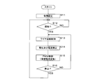
- FIG. It is a flowchart which shows the procedure of the arc welding method which concerns on this Embodiment 1.
- FIG. It is a sectional side view which shows the base material of welding object.
- FIG. It is a graph which shows the fluctuation
- FIG. 1 It is a graph which shows the fluctuation
- FIG. It is a graph which shows the welding current value which concerns on the Example of this Embodiment 3.
- FIG. It is a graph which shows the fluctuation
- FIG. 1 It is a graph which shows the fluctuation
- FIG. 1 is a schematic diagram showing one configuration of an arc welding apparatus according to the first embodiment.
- the arc welding apparatus according to the first embodiment is a consumable electrode type gas shielded arc welding machine capable of butt welding the base material 4 having a plate thickness of 9 to 30 mm in one pass.
- the arc welding apparatus according to the first embodiment raises and lowers the position of the distal end portion 5a of the welding wire 5 that has entered the buried space 6a (see FIG. 4) by controlling the welding current Iw, thereby leading the distal end portion 5a of the welding wire 5.
- the arc welding apparatus includes a welding power source 1, a torch 2, and a wire feeding unit 3.
- the torch 2 is made of a conductive material such as a copper alloy, and has a cylindrical shape that guides the welding wire 5 to the welded portion of the base material 4 and supplies the welding current Iw necessary for generating the arc 7 (see FIG. 4).
- Contact chip The contact tip contacts the welding wire 5 that is inserted through the contact tip, and supplies the welding current Iw to the welding wire 5.
- the torch 2 has a hollow cylindrical shape surrounding the contact tip, and has a nozzle for injecting a shielding gas to the welded portion.
- the shielding gas is for preventing the base material 4 and the welding wire 5 melted by the arc 7 from being oxidized.
- the shield gas is, for example, carbon dioxide, a mixed gas of carbon dioxide and argon, an inert gas such as argon, or the like.
- the welding wire 5 is, for example, a solid wire and has a diameter of 0.9 mm to 1.6 mm and functions as a consumable electrode.
- the welding wire 5 is, for example, a pack wire housed in a pail pack in a spirally wound state, or a reel wire wound around a wire reel.
- the wire feeding unit 3 includes a feeding roller that feeds the welding wire 5 to the torch 2 and a motor that rotates the feeding roller.
- the wire feeding unit 3 rotates the feeding roller to pull out the welding wire 5 from the wire reel and supplies the drawn welding wire 5 to the torch 2.
- the feeding method of the welding wire 5 is an example, and is not particularly limited.
- the welding power source 1 is connected to the contact tip of the torch 2 and the base material 4 through a power supply cable, and supplies a power source 11 that supplies a welding current Iw, and a feed rate control unit that controls the feed rate of the welding wire 5.
- the power supply unit 11 and the feed speed control unit 12 may be configured separately.
- the power supply unit 11 includes a power supply circuit 11a that outputs a PWM-controlled DC current, an output voltage setting circuit 11b, a frequency setting circuit 11c, a current amplitude setting circuit 11d, an average current setting circuit 11e, a voltage detection unit 11f, and a current detection unit 11g. And a comparison circuit 11h.
- the voltage detection unit 11f detects the welding voltage Vw and outputs a voltage value signal Ed indicating the detected voltage value to the comparison circuit 11h.
- the current detector 11g detects, for example, a welding current Iw that is supplied from the welding power source 1 to the welding wire 5 via the torch 2 and flows through the arc 7, and outputs a current value signal Id indicating the detected current value to an output voltage setting circuit. To 11b.
- the frequency setting circuit 11c outputs a frequency setting signal for setting a frequency for periodically changing the welding voltage Vw and the welding current Iw between the base material 4 and the welding wire 5 to the output voltage setting circuit 11b.
- the frequency setting circuit 11c is a frequency setting signal indicating a frequency of 10 Hz to 1000 Hz, preferably a frequency of 50 Hz to 300 Hz, more preferably a frequency of 80 Hz to 200 Hz. Is output.
- the current amplitude setting circuit 11d outputs an amplitude setting signal for setting the amplitude of the welding current Iw that varies periodically to the output voltage setting circuit 11b.
- the amplitude is a current difference between the minimum current value and the maximum current value of the fluctuating welding current Iw.
- the current amplitude setting circuit 11d has a current amplitude of 50A or more, preferably a current amplitude of 100A or more and 500A or less, more preferably an amplitude indicating a current amplitude of 200A or more and 400A or less. Outputs a setting signal.
- the average current setting circuit 11e outputs an average current setting signal for setting the average current of the welding current Iw that varies periodically to the output voltage setting circuit 11b and the feed speed control unit 12.
- the average current setting circuit 11e has an average current of 300A or more, preferably an average current of 300A to 1000A, more preferably an average current of 500A to 800A.
- An average current setting signal indicating is output.
- the output voltage setting circuit 11b Based on the current value signal Id, the frequency setting signal, the amplitude setting signal, and the average current setting signal output from each unit, the output voltage setting circuit 11b makes the welding current Iw have the target frequency, current amplitude, and average current. For example, an output voltage setting signal Ecr indicating a rectangular wave target voltage is generated, and the generated output voltage setting signal Ecr is output to the comparison circuit 11h.
- the comparison circuit 11h compares the voltage value signal Ed output from the voltage detection unit 11f with the output voltage setting signal Ecr output from the output voltage setting circuit 11b, and sends a difference signal Ev indicating the difference to the power supply circuit 11a. Output.
- the power supply circuit 11a includes an AC-DC converter for AC / DC conversion of commercial AC, an inverter circuit for converting AC / DC converted DC into required AC by switching, a rectifier circuit for rectifying the converted AC, and the like.
- the power supply circuit 11a performs PWM control of the inverter according to the difference signal Ev output from the comparison circuit 11h, and outputs a voltage to the welding wire 5.
- a welding voltage Vw that varies periodically is applied between the base material 4 and the welding wire 5, and the welding current Iw is energized.
- the welding power source 1 is configured such that an output instruction signal is input from the outside via a control communication line (not shown), and the power source unit 11 is welded to the power circuit 11a using the output instruction signal as a trigger.
- the output instruction signal is output from the welding robot to the welding power source 1, for example.
- the output instruction signal is output from the torch 2 side to the welding power source 1 when a hand operation switch provided on the torch 2 side is operated.
- FIG. 2 is a flowchart showing the procedure of the arc welding method according to the first embodiment
- FIG. 3 is a side sectional view showing the base material 4 to be welded.
- a pair of base materials 4 to be joined by welding are arranged in an arc welding apparatus, and various settings of the welding power source 1 are performed (step S11).
- a plate-like first base material 41 and a second base material 42 are prepared, and end surfaces 41 a and 42 a which are welded portions are abutted and arranged at predetermined welding work positions.
- the first and second base materials 41 and 42 are steel plates such as mild steel, carbon steel for machine structure, alloy steel for machine structure, and the thickness is 9 mm or more and 30 mm or less.
- the welding power source 1 sets the welding conditions of the welding current Iw within the range of the frequency of 10 Hz or more and 1000 Hz or less, the average current of 300 A or more, and the current amplitude of 50 A or more.
- the welding current Iw may all be set by the welding operator, or the welding power source 1 accepts the execution of the welding method according to the first embodiment at the operation unit and automatically sets all the conditions. You may comprise so that it may be performed. Also, the welding power source 1 accepts some welding conditions such as average current at the operation unit, determines the remaining welding conditions that match the accepted some welding conditions, and performs the condition setting semi-automatically. It may be configured.
- the welding power source 1 determines whether or not the output start condition for the welding current Iw is satisfied (step S12). Specifically, the welding power source 1 determines whether or not a welding output instruction signal is input. When it is determined that the output instruction signal is not input and the output start condition of the welding current Iw is not satisfied (step S12: NO), the welding power source 1 stands by in the input waiting state for the output instruction signal.
- the feed speed control part 12 of the welding power supply 1 sends the feed instruction signal which instruct
- the welding wire 5 is fed at a predetermined speed (step S13).
- the feeding speed of the welding wire 5 is set within a range of about 5 to 100 m / min, for example.
- the feeding speed control unit 12 determines the feeding speed according to the average current setting signal output from the average current setting circuit 11e. Note that the feeding speed of the welding wire 5 may be a constant speed or may be periodically changed. Moreover, you may comprise so that a welding operator may set the feed speed of a wire directly.
- the power supply unit 11 of the welding power source 1 detects the welding voltage Vw and the welding current Iw with the voltage detection unit 11f and the current detection unit 11g (step S14), and the frequency, current amplitude, and average of the detected welding current Iw.
- PWM control is performed so that the current matches the set welding condition and the welding current Iw periodically varies (step S15).
- the power supply unit 11 of the welding power source 1 determines whether or not to stop the output of the welding current Iw (step S16). Specifically, the welding power source 1 determines whether or not the input of the output instruction signal is continued. When the input of the output instruction signal continues and it is determined that the output of the welding current Iw is not stopped (step S16: NO), the power supply unit 11 returns the process to step S13 and continues the output of the welding current Iw.
- step S16 When it determines with stopping the output of the welding current Iw (step S16: YES), the power supply part 11 returns a process to step S12.
- the power supply unit 11 controls the welding current Iw so that the frequency of the welding current Iw is 10 Hz to 1000 Hz, the average current is 300 A or more, and the current amplitude is 50 A or more.
- the power supply unit 11 controls the welding current Iw so that the frequency of the welding current Iw is 50 Hz to 300 Hz, the average current is 300 A to 1000 A, and the current amplitude is 100 A to 500 A.
- FIG. 4 is a schematic diagram showing the state of droplet transfer by periodically changing the welding current Iw.
- the welding current Iw is periodically changed under the above welding conditions, the concave shape formed of the base metal 4 melted by the heat of the arc 7 generated between the tip 5a of the welding wire 5 and the welded portion and the molten metal of the welding wire 5 is obtained.
- the molten portion 6 is formed in the base material 4.
- the state of the arc 7 was photographed with a high-speed camera, as shown in the left diagram of FIG.
- a first state in which the arc 7 flies from the tip 5a of the welding wire 5 to the bottom 61 of the melting portion 6 and a first state in which the arc 7 flies from the tip 5a of the welding wire 5 to the side 62 of the melting portion 6 is performed.
- the first state is in the small current period where the average value of the welding current Iw is small
- the second state is in the large current period where the average value of the welding current Iw is large.
- the first state is a state in which the droplet transfer form of the welding wire 5 is drop transfer.
- the second state is a state in which, for example, the droplet transfer form of the welding wire 5 is a rotating transfer or a pendulum transfer.
- the drop transition is an example of a mode in which droplets migrate from the tip 5a of the welding wire 5 to the bottom 61 of the melted part 6, and the rotating transition from the tip 5a of the welding wire 5 to the side part 62 of the melted part 6. It is an example of the form which moves to a droplet.
- the pendulum transition is performed in such a manner that the liquid column and the arc 7 formed at the distal end portion 5a of the welding wire 5 swing in a pendulum shape on the same plane, and the entire plane is centered on the protruding direction of the welding wire 5. It is a characteristic droplet transfer form that rotates little by little.
- the molten metal closes the buried space 6a and tends to flow in the direction in which the tip 5a of the welding wire 5 is buried, but in the second state, the arc 7 jumps to the side portion 62 of the molten portion 6 and the molten portion 6
- the molten metal is pushed back in the direction away from the welding wire 5, and the buried space 6a is stabilized in a concave state.
- the tip 5a of the welding wire 5 is shortened as a result of the transfer of the droplet at the tip 5a of the welding wire 5 melted by a large current.
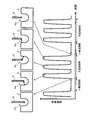
- FIG. 5 is a graph showing fluctuations in the welding current Iw according to the first embodiment.
- the horizontal axis of the graph indicates time, and the vertical axis indicates the welding current Iw.
- the state of droplet transfer accompanying the change in the welding current Iw is schematically shown in the upper part of the graph.
- Each schematic diagram shows the welding wire 5 and the state of droplet transfer when the welding current Iw indicated by the dotted-line circle is supplied.
- FIG. 6, FIG. 7, FIG. 8, and FIG. 10 below similarly show the state of the welding wire 5 and droplet transfer.
- the power source unit 11 causes the welding current Iw during a large current period to be transferred a plurality of times during each large current period from the tip 5a of the welding wire 5 to the side portion 62 of the melted part 6.
- the power supply unit 11 controls the welding current Iw so that a pulsed large current is supplied a plurality of times in a large current period.
- the power supply unit 11 supplies a pulsed large current three times during a large current period.
- the magnitude of the pulsed current is substantially the same each time.
- the welding current Iw in the small current period is, for example, 200 A
- the pulsed large current in the large current period is, for example, 800 A.
- the distal end portion 5 a of the welding wire 5 penetrates deeply into the buried space 6 a, and the arc 7 is irradiated to the bottom portion 61 of the molten portion 6.
- the arc 7 is applied to the bottom 61 of the melted part 6, deep penetration is obtained.
- the large current period as shown in the three schematic diagrams in the center of FIG. 5, each time a pulsed large current is supplied, the solution is little by little from the tip portion 5 a of the welding wire 5 to the side portion 62 of the molten portion 6. Transition takes place and the wire tip position transitions from a low state to a high state.
- the tip portion 5a of the welding wire 5 When the tip portion 5a of the welding wire 5 is at a high position, the arc 7 is applied to the side portion 62 of the molten portion 6, and the buried space 6a is stabilized. Moreover, since droplet transfer is performed little by little, the occurrence of spatter is effectively suppressed.
- the wire tip position transitions from a high state to a low state again. Thereafter, the state transition is repeated.
- the welding current Iw By varying the welding current Iw in this way, in buried arc welding, deep penetration can be obtained while stably maintaining the buried space 6a, and spatter can be suppressed, and one pass of a stable thick plate can be achieved. Through welding is possible.
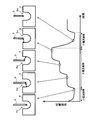
- FIG. 6 is a graph showing fluctuations in the welding current Iw according to the comparative example.
- the horizontal axis of the graph indicates time, and the vertical axis indicates the welding current Iw.
- the state of droplet transfer accompanying the change in the welding current Iw is schematically shown in the upper part of the graph.
- the large current period and the small current period have the same length, and the required large current is constantly supplied at a time during the large current period. If the welding current Iw suddenly increases and a large current is supplied at one time with the tip 5a of the welding wire 5 entering the buried space 6a, as shown in the two schematic diagrams in the center of FIG. The welding wire 5 is rapidly melted to form a long liquid column, and a large droplet moves near the opening of the buried space 6a. In the drawing, a short circuit occurs between the welding wire 5 and the melted portion 6 at the time indicated by a broken star, and as a result, large sputtered particles are generated.
- the buried space 6a is stably maintained.
- the occurrence of spatter can be suppressed, and stable one-pass through welding of thick plates can be achieved.
- the undulation of molten metal can be suppressed by periodically varying the welding current Iw, and the occurrence of bead turbulence and sag. Can be prevented.
- FIG. 7 is a graph showing fluctuations in the welding current Iw according to the second embodiment.
- the horizontal axis of the graph indicates time, and the vertical axis indicates the welding current Iw.
- the state of droplet transfer accompanying the change in the welding current Iw is schematically shown in the upper part of the graph.
- the power supply unit 11 performs control so that the large current period is longer than the small current period and the welding current Iw in the large current period is constant.
- the length and current value of the large current period are such a period and current value that droplet transfer can be performed a plurality of times in the large current period.
- the welding current Iw in the small current period is 200 A
- the welding current Iw in the large current period is 500 A.
- the droplet transfer of the welding wire 5 can be performed little by little, the length of the liquid column is reduced, and spatter is generated. Can be suppressed. Therefore, in buried arc welding, spatter can be suppressed while stably maintaining the buried space 6a, and stable one-pass through welding of a thick plate becomes possible.
- FIG. 8 is a graph showing fluctuations in the welding current Iw according to the third embodiment.
- the horizontal axis of the graph indicates time, and the vertical axis indicates the welding current Iw.
- the state of droplet transfer accompanying the change in the welding current Iw is schematically shown in the upper part of the graph.
- the power supply unit 11 controls the output of the welding current Iw so that the welding current Iw increases stepwise in the large current period. For example, as shown in FIG. 8, the power supply unit 11 increases the welding current Iw in three stages until the maximum welding current Iw is reached. The period during which the required welding current Iw is output at each stage is substantially the same, and the increase amount of the welding current Iw is also substantially the same.
- the diameter of the welding wire 5 is 1.2 mm, and the welding power source 1 has a base material 4 under welding conditions in which the feeding speed of the welding wire 5 is 40 m / min, the average current of the welding current Iw is 540 A, and the average voltage is 51 V. Perform buried arc welding.
- FIG. 9 is a graph showing the welding current Iw value according to the example.
- the horizontal axis of the graph indicates time, and the vertical axis indicates the welding current Iw.
- the welding power source 1 supplies a welding current Iw of 200 A in a small current period, and supplies a welding current Iw while increasing the current value in three stages, 400 A, 600 A, and 800 A in a large current period. To do.
- the cycle in which the unit waveform consisting of the small current period and the large current period is repeated is 100 Hz. Since droplet transfer occurs once at each stage where the welding current Iw increases in a large current period, the tip position of the welding wire 5 can be raised while suppressing the formation of a long liquid column on the welding wire 5.
- the buried space 6a can be stabilized.
- FIG. 10 is a graph showing fluctuations in the welding current Iw according to the fourth embodiment.
- the horizontal axis of the graph indicates time, and the vertical axis indicates the welding current Iw.
- the state of droplet transfer accompanying the change in the welding current Iw is schematically shown in the upper part of the graph.
- the power supply unit 11 controls the output of the welding current Iw so that the welding current Iw increases stepwise in the large current period. For example, as shown in FIG. 10, the power supply unit 11 increases the welding current Iw in two stages until the maximum welding current Iw is reached.
- the period of the previous stage is longer than the period of the subsequent stage, and the increase amount of the welding current Iw in the previous stage is larger than the increase amount of the welding current Iw in the subsequent stage.
- the period of the previous stage is about twice the period of the subsequent stage, and the increase amount of the welding current Iw in the previous stage is about twice the increase amount of the welding current Iw in the subsequent stage from the previous stage.
- the generation of spatter can be suppressed while stably maintaining the buried space 6a in the buried arc, and a stable thick plate 1 pass through welding is possible.
Abstract
Description
小電流期間においては、溶接ワイヤの先端部と、溶融部分の底部との間にアークが発生し、溶融部分の底部へ照射されるアークによって、深い溶込みが得られる。
大電流期間においては、溶接ワイヤの先端部と、溶融部分の側部との間にアークが発生する。アークの熱によって溶融した母材及び溶接ワイヤの溶融金属は、溶接ワイヤの先端部が埋没される方向へ流れようとするが、溶接ワイヤの先端部から溶融部分の側部へ照射されるアークの力によって押し返され、先端部が溶融部分に囲まれた状態で安定化する。
更に、ワイヤ先端位置が上下する埋もれアーク溶接において、ワイヤ先端位置が低い状態から高い状態へ遷移する過程で溶滴移行を複数回に分けて行うことにより、一回の溶滴移行で形成される液柱の長さを短く制限することができ、スパッタの発生を抑制することができる。
以上の通り、本発明によれば、埋もれアーク溶接において、埋もれ空間を安定的に維持しつつ、スパッタの発生を抑制することができる。 In the present invention, the tip of the welding wire enters the buried space surrounded by the concave melted portion, and a buried arc is generated. Specifically, the tip of the welding wire is surrounded by the melted portion, and by periodically changing the welding current, the position of the tip of the wire in the buried space can be moved up and down. An arc is generated between the bottom and sides of the melted part.
In the small current period, an arc is generated between the tip of the welding wire and the bottom of the melted portion, and a deep penetration is obtained by the arc irradiated to the bottom of the melted portion.
During a high current period, an arc is generated between the tip of the welding wire and the side of the molten portion. The base metal melted by the heat of the arc and the molten metal of the welding wire tend to flow in the direction in which the tip of the welding wire is buried, but the arc of the arc irradiated from the tip of the welding wire to the side of the molten portion It is pushed back by force and stabilized in a state where the tip is surrounded by the melted part.
Furthermore, in buried arc welding where the wire tip position moves up and down, it is formed by one droplet transfer by performing droplet transfer in multiple steps in the process of transition from a low wire state to a high state. The length of the liquid column can be limited to be short, and the generation of spatter can be suppressed.
As described above, according to the present invention, it is possible to suppress the occurrence of spatter while stably maintaining the buried space in the buried arc welding.
しかし、前記周波数にて溶接電流を周期的に変動させることにより、大きな波打ち周期よりも高周期で溶融金属を微振動させ、溶融金属の大きな波打ちを抑えることができる。 In the buried arc welding of the present invention, the molten metal of the base metal and the welding wire melted by the heat of the arc is increased, the molten metal is undulated by the arc, and the shape of the bead solidified by the molten metal is also periodically large. May be disturbed.
However, by periodically fluctuating the welding current at the frequency, the molten metal can be slightly vibrated at a period higher than a large wave period, and the large wave of the molten metal can be suppressed.
(実施形態1)
図1は、本実施形態1に係るアーク溶接装置の一構成を示す模式図である。本実施形態1に係るアーク溶接装置は、板厚が9~30mmの母材4を1パスで突き合わせ溶接することが可能な消耗電極式のガスシールドアーク溶接機である。特に本実施形態1に係るアーク溶接装置は、溶接電流Iwの制御によって、埋もれ空間6a(図4参照)に進入した溶接ワイヤ5の先端部5aの位置を上下させ、溶接ワイヤ5の先端部5aの位置が低い状態から高い状態へ遷移させる過程で複数回に分けて溶滴移行を行うことにより、埋もれ空間6aを安定的に維持しつつ、スパッタの発生を抑制することを可能にするものである。
本実施形態1に係るアーク溶接装置は、溶接電源1、トーチ2及びワイヤ送給部3を備える。 Hereinafter, the present invention will be described in detail with reference to the drawings illustrating embodiments thereof.
(Embodiment 1)
FIG. 1 is a schematic diagram showing one configuration of an arc welding apparatus according to the first embodiment. The arc welding apparatus according to the first embodiment is a consumable electrode type gas shielded arc welding machine capable of butt welding the
The arc welding apparatus according to the first embodiment includes a welding power source 1, a torch 2, and a wire feeding unit 3.
そして、溶接電源1は、周波数10Hz以上1000Hz以下、平均電流300A以上、電流振幅50A以上の範囲内で溶接電流Iwの溶接条件を設定する。 FIG. 2 is a flowchart showing the procedure of the arc welding method according to the first embodiment, and FIG. 3 is a side sectional view showing the
And the welding power source 1 sets the welding conditions of the welding current Iw within the range of the frequency of 10 Hz or more and 1000 Hz or less, the average current of 300 A or more, and the current amplitude of 50 A or more.
本実施形態1に係るアーク溶接方法においては、電源部11は、溶接電流Iwの周波数が10Hz以上1000Hz以下、平均電流が300A以上、電流振幅が50A以上になるように、溶接電流Iwを制御する。
好ましくは、電源部11は、溶接電流Iwの周波数が50Hz以上300Hz以下、平均電流が300A以上1000A以下、電流振幅が100A以上500A以下になるように、溶接電流Iwを制御する。 Hereinafter, an outline of the periodic variation of the welding current Iw and droplet transfer will be described.
In the arc welding method according to the first embodiment, the
Preferably, the
ドロップ移行は、溶接ワイヤ5の先端部5aから溶融部分6の底部61へ溶滴移行する形態の一例であり、ローテーティング移行は、溶接ワイヤ5の先端部5aから溶融部分6の側部62へ溶滴移行する形態の一例である。また、振り子移行は、溶接ワイヤ5の先端部5aに形成された液柱及びアーク7が、同一平面上を振り子状に揺動しつつ、溶接ワイヤ5の突き出し方向を中心軸として当該平面が全体として少しずつ回転していく特徴的な溶滴移行形態である。
溶融金属は、埋もれ空間6aが閉口し、溶接ワイヤ5の先端部5aが埋没される方向へ流れようとするが、第2状態において溶融部分6の側部62にアーク7が飛び、溶融部分6の溶融金属は溶接ワイヤ5から離隔する方向へ押し返され、埋もれ空間6aは凹状の状態で安定化する。なお、図4右図では、大電流によって溶融した溶接ワイヤ5の先端部5aの溶滴が移行した結果、溶接ワイヤ5の先端部5aが短くなっている。
このような第1状態及び第2状態を80Hz以上200Hz以下で変動させることによって、大きな波打ち周期よりも高周期で溶融金属を微振動させることができ、溶融金属の波打ちが抑えられる。 Specifically, a first state in which the arc 7 flies from the
The drop transition is an example of a mode in which droplets migrate from the
The molten metal closes the buried
By varying the first state and the second state at 80 Hz or more and 200 Hz or less, the molten metal can be finely vibrated at a period higher than a large waving period, and the undulation of the molten metal can be suppressed.
図5は、本実施形態1に係る溶接電流Iwの変動を示すグラフである。グラフの横軸は時間を示し、縦軸は溶接電流Iwを示している。また、グラフの上部に、溶接電流Iwの変化に伴う溶滴移行の様子が模式的に図示されている。各模式図は、破線の丸印で示された溶接電流Iwが供給されているときの溶接ワイヤ5及び溶滴移行の状態を示している。以下の図6、図7、図8、図10における模式図も同様にして、溶接ワイヤ5及び溶滴移行の状態を示している。 Next, details of control of the welding current Iw and droplet transfer will be described.
FIG. 5 is a graph showing fluctuations in the welding current Iw according to the first embodiment. The horizontal axis of the graph indicates time, and the vertical axis indicates the welding current Iw. In addition, the state of droplet transfer accompanying the change in the welding current Iw is schematically shown in the upper part of the graph. Each schematic diagram shows the
大電流期間においては、図5中央の3つの模式図に示すように、パルス状の大電流が供給される都度、溶接ワイヤ5の先端部5aから溶融部分6の側部62へ、少量ずつ溶液移行が行われ、ワイヤ先端位置が低い状態から高い状態へ遷移する。溶接ワイヤ5の先端部5aが高い位置にある場合、アーク7は溶融部分6の側部62に照射され、埋もれ空間6aが安定化される。また、溶滴移行が少量ずつ行われるため、スパッタの発生が効果的に抑制される。
再び小電流期間になると、図5右端及び左端の模式図に示すように、ワイヤ先端位置が高い状態から再び低い状態へ遷移する。
以下、上記状態遷移が繰り返し行われる。このように溶接電流Iwを変動させることにより、埋もれアーク溶接において、埋もれ空間6aを安定的に維持しつつ深い溶け込みが得られ、しかもスパッタの発生を抑えることができ、安定した厚板の1パス貫通溶接が可能になる。 In the small current period, as shown in the schematic diagram at the left end of FIG. 5, the
In the large current period, as shown in the three schematic diagrams in the center of FIG. 5, each time a pulsed large current is supplied, the solution is little by little from the
In the small current period again, as shown in the schematic diagrams of the right end and the left end in FIG. 5, the wire tip position transitions from a high state to a low state again.
Thereafter, the state transition is repeated. By varying the welding current Iw in this way, in buried arc welding, deep penetration can be obtained while stably maintaining the buried
実施形態2に係るアーク溶接方法及びアーク溶接装置は、溶接電流Iwの制御方法が実施形態1と異なるため、以下では主にかかる相違点について説明する。その他の構成及び作用効果は実施形態1と同様であるため、対応する箇所には同様の符号を付して詳細な説明を省略する。 (Embodiment 2)
Since the arc welding method and the arc welding apparatus according to the second embodiment are different from the first embodiment in the method of controlling the welding current Iw, the following mainly describes the differences. Since other configurations and operational effects are the same as those of the first embodiment, the corresponding portions are denoted by the same reference numerals, and detailed description thereof is omitted.
実施形態3に係るアーク溶接方法及びアーク溶接装置は、溶接電流Iwの制御方法が実施形態1と異なるため、以下では主にかかる相違点について説明する。その他の構成及び作用効果は実施形態1と同様であるため、対応する箇所には同様の符号を付して詳細な説明を省略する。 (Embodiment 3)
Since the arc welding method and the arc welding apparatus according to the third embodiment differ from the first embodiment in the method for controlling the welding current Iw, the following mainly describes the differences. Since other configurations and operational effects are the same as those of the first embodiment, the corresponding portions are denoted by the same reference numerals, and detailed description thereof is omitted.
溶接ワイヤ5の直径は1.2mmであり、溶接電源1は、溶接ワイヤ5の送給速度が40m/分、溶接電流Iwの平均電流は540A,平均電圧が51Vの溶接条件にて母材4の埋もれアーク溶接を実行する。 (Example)
The diameter of the
実施形態4に係るアーク溶接方法及びアーク溶接装置は、溶接電流Iwの制御方法が実施形態1と異なるため、以下では主にかかる相違点について説明する。その他の構成及び作用効果は実施形態1と同様であるため、対応する箇所には同様の符号を付して詳細な説明を省略する。 (Embodiment 4)
Since the arc welding method and the arc welding apparatus according to the fourth embodiment are different from the first embodiment in the method for controlling the welding current Iw, the following mainly describes the differences. Since other configurations and operational effects are the same as those of the first embodiment, the corresponding portions are denoted by the same reference numerals, and detailed description thereof is omitted.
2 トーチ
3 ワイヤ送給部
4 母材
5 溶接ワイヤ
5a 先端部
6 溶融部分
6a 埋もれ空間
61 底部
62 側部
7 アーク
11 電源部
11a 電源回路
11b 出力電圧設定回路
11c 周波数設定回路
11d 電流振幅設定回路
11e 平均電流設定回路
11f 電圧検出部
11g 電流検出部
11h 比較回路
12 送給速度制御部
41 第1母材
42 第2母材
Vw 溶接電圧
Iw 溶接電流
Ecr 出力電圧設定信号
Ed 電圧値信号
Id 電流値信号
Ev 差分信号 DESCRIPTION OF SYMBOLS 1 Welding power supply 2 Torch 3
Claims (7)
- 母材の被溶接部に溶接ワイヤを送給すると共に、該溶接ワイヤに平均電流300A以上の溶接電流を供給することによって、前記溶接ワイヤの先端部及び被溶接部間にアークを発生させ、前記母材を溶接する消耗電極式のアーク溶接方法であって、
前記先端部及び被溶接部間に発生したアークによって前記母材に形成された凹状の溶融部分によって囲まれる空間に前記先端部が進入する速度で、前記溶接ワイヤを送給し、
前記溶接電流の平均値が小さく、前記先端部から前記溶融部分の底部へ溶滴移行する小電流期間と、前記溶接電流の平均値が大きく、前記先端部から前記溶融部分の側部へ溶滴移行する大電流期間とを周期的に変動させ、
更に、前記大電流期間における前記溶接電流を、前記先端部から前記側部への溶滴移行が各大電流期間で複数回行われるように制御する
アーク溶接方法。 While feeding a welding wire to the welded portion of the base material and supplying a welding current with an average current of 300 A or more to the welding wire, an arc is generated between the tip portion of the welding wire and the welded portion, A consumable electrode type arc welding method for welding a base material,
The welding wire is fed at a speed at which the tip portion enters a space surrounded by a concave melted portion formed in the base material by an arc generated between the tip portion and the welded portion,
A small current period in which the average value of the welding current is small and droplets move from the tip to the bottom of the molten portion, and the average value of the welding current is large and droplets from the tip to the side of the molten portion Periodically changing the high current period to transition,
Furthermore, the arc welding method of controlling the welding current in the large current period so that droplet transfer from the tip portion to the side portion is performed a plurality of times in each large current period. - 前記大電流期間でパルス状の大電流を複数回供給する
請求項1に記載のアーク溶接方法。 The arc welding method according to claim 1, wherein a pulsed large current is supplied a plurality of times during the large current period. - 前記大電流期間は前記小電流期間よりも長く、該大電流期間における前記溶接電流は一定である
請求項1に記載のアーク溶接方法。 The arc welding method according to claim 1, wherein the large current period is longer than the small current period, and the welding current in the large current period is constant. - 前記大電流期間で前記溶接電流を段階的に増大させる
請求項1に記載のアーク溶接方法。 The arc welding method according to claim 1, wherein the welding current is increased stepwise during the large current period. - 前記大電流期間で最大の溶接電流が供給される段階の前段階における前記溶接電流と、前記小電流期間における前記溶接電流との電流差は、前記前段階における前記溶接電流と、前記最大の溶接電流との電流差よりも大きい
請求項4に記載のアーク溶接方法。 The difference in current between the welding current in the stage before the maximum welding current is supplied in the large current period and the welding current in the small current period is the welding current in the previous stage and the maximum welding. The arc welding method according to claim 4, wherein the arc welding method is larger than a current difference from the current. - 前記大電流期間及び前記小電流期間を10Hz以上1000Hz以下の周期で変動させる
請求項1~請求項5までのいずれか一項に記載のアーク溶接方法。 The arc welding method according to any one of claims 1 to 5, wherein the large current period and the small current period are varied in a cycle of 10 Hz to 1000 Hz. - 母材の被溶接部に溶接ワイヤを送給するワイヤ送給部と、該溶接ワイヤに溶接電流を供給する電源部とを備え、前記溶接ワイヤに平均電流300A以上の溶接電流を供給することによって、前記溶接ワイヤの先端部及び被溶接部間にアークを発生させ、前記母材を溶接する消耗電極式のアーク溶接装置であって、
前記ワイヤ送給部は、
前記先端部及び被溶接部間に発生したアークによって前記母材に形成された凹状の溶融部分によって囲まれる空間に前記先端部が進入する速度で、前記溶接ワイヤを送給し、
前記電源部は、
前記溶接電流の平均値が小さく、前記先端部から前記溶融部分の底部へ溶滴移行する小電流期間と、前記溶接電流の平均値が大きく、前記先端部から前記溶融部分の側部へ溶滴移行する大電流期間とを周期的に変動させ、かつ、前記大電流期間における前記溶接電流を、前記先端部から前記側部への溶滴移行が各大電流期間で複数回行われるように制御する
アーク溶接装置。 A wire feeding portion for feeding a welding wire to a welded portion of the base material, and a power supply portion for supplying a welding current to the welding wire, and supplying a welding current having an average current of 300 A or more to the welding wire. A consumable electrode type arc welding apparatus for generating an arc between a tip portion and a welded portion of the welding wire and welding the base material,
The wire feeding unit is
The welding wire is fed at a speed at which the tip portion enters a space surrounded by a concave melted portion formed in the base material by an arc generated between the tip portion and the welded portion,
The power supply unit is
A small current period in which the average value of the welding current is small and droplets move from the tip to the bottom of the molten portion, and the average value of the welding current is large and droplets from the tip to the side of the molten portion The welding current during the large current period is controlled so that droplet transfer from the tip portion to the side portion is performed a plurality of times during each large current period. Arc welding equipment.
Priority Applications (5)
| Application Number | Priority Date | Filing Date | Title |
|---|---|---|---|
| CN201780073640.7A CN110023021B (en) | 2016-12-06 | 2017-12-04 | Arc welding method and arc welding device |
| JP2018554985A JP6959941B2 (en) | 2016-12-06 | 2017-12-04 | Arc welding method and arc welding equipment |
| US16/463,120 US11407054B2 (en) | 2016-12-06 | 2017-12-04 | Arc welding method and arc welding device |
| EP17878292.6A EP3552748B1 (en) | 2016-12-06 | 2017-12-04 | Arc welding method and arc welding device |
| KR1020197014863A KR102324216B1 (en) | 2016-12-06 | 2017-12-04 | Arc welding method and arc welding device |
Applications Claiming Priority (2)
| Application Number | Priority Date | Filing Date | Title |
|---|---|---|---|
| JP2016-236944 | 2016-12-06 | ||
| JP2016236944 | 2016-12-06 |
Publications (1)
| Publication Number | Publication Date |
|---|---|
| WO2018105548A1 true WO2018105548A1 (en) | 2018-06-14 |
Family
ID=62491093
Family Applications (1)
| Application Number | Title | Priority Date | Filing Date |
|---|---|---|---|
| PCT/JP2017/043442 WO2018105548A1 (en) | 2016-12-06 | 2017-12-04 | Arc welding method and arc welding device |
Country Status (6)
| Country | Link |
|---|---|
| US (1) | US11407054B2 (en) |
| EP (1) | EP3552748B1 (en) |
| JP (1) | JP6959941B2 (en) |
| KR (1) | KR102324216B1 (en) |
| CN (1) | CN110023021B (en) |
| WO (1) | WO2018105548A1 (en) |
Cited By (1)
| Publication number | Priority date | Publication date | Assignee | Title |
|---|---|---|---|---|
| CN108890082A (en) * | 2018-07-19 | 2018-11-27 | 唐山松下产业机器有限公司 | Arc welding control method and device and welding equipment |
Families Citing this family (3)
| Publication number | Priority date | Publication date | Assignee | Title |
|---|---|---|---|---|
| US10710187B2 (en) * | 2015-08-25 | 2020-07-14 | Daihen Corporation | Welding method and arc welding device |
| KR102237436B1 (en) * | 2016-03-11 | 2021-04-07 | 가부시키가이샤 다이헨 | Arc welding system and wire feeding device |
| US20210402502A1 (en) * | 2019-12-25 | 2021-12-30 | Daihen Corporation | Arc Welding Method and Arc Welding Device |
Citations (4)
| Publication number | Priority date | Publication date | Assignee | Title |
|---|---|---|---|---|
| JP2000263228A (en) * | 1999-03-18 | 2000-09-26 | Hitachi Zosen Corp | Selecting method for welding condition |
| JP2001246471A (en) * | 2000-02-29 | 2001-09-11 | National Institute For Materials Science | Method of consumable electrode type gas shielded arc welding and equipment for the same |
| JP2007229775A (en) | 2006-03-02 | 2007-09-13 | Daihen Corp | Consumable electrode arc welding method |
| JP2017144480A (en) * | 2016-02-18 | 2017-08-24 | 株式会社ダイヘン | Arc-welding method and arc-welding device |
Family Cites Families (11)
| Publication number | Priority date | Publication date | Assignee | Title |
|---|---|---|---|---|
| US6025573A (en) * | 1998-10-19 | 2000-02-15 | Lincoln Global, Inc. | Controller and method for pulse welding |
| CN1199760C (en) * | 2003-01-16 | 2005-05-04 | 中国重型汽车集团有限公司 | Technique for welding car axle housing made by punching medium heavy steel plates |
| AT413953B (en) * | 2003-11-25 | 2006-07-15 | Fronius Int Gmbh | METHOD AND CIRCUIT FOR TOUCH-FREE IGNITION OF A WELDING ARC |
| DE102005024802A1 (en) * | 2005-05-27 | 2006-11-30 | Ewm Hightec Welding Gmbh | Welding current source and method for MIG / MAG welding |
| JP4498263B2 (en) * | 2005-11-08 | 2010-07-07 | 株式会社神戸製鋼所 | Pulse arc welding method |
| US9352410B2 (en) * | 2013-03-15 | 2016-05-31 | Lincoln Global, Inc. | System for and method of narrow-groove joining of metals |
| US10543551B2 (en) * | 2013-09-16 | 2020-01-28 | Illinois Tool Works Inc. | Synchronized rotating arc welding method and system |
| CN105792973B (en) * | 2014-02-24 | 2018-02-02 | 株式会社达谊恒 | Arc-welding method |
| WO2016059805A1 (en) * | 2014-10-17 | 2016-04-21 | パナソニックIpマネジメント株式会社 | Arc welding control method |
| US10710187B2 (en) * | 2015-08-25 | 2020-07-14 | Daihen Corporation | Welding method and arc welding device |
| CN109715335B (en) * | 2016-09-05 | 2021-05-11 | 松下知识产权经营株式会社 | Arc welding control method |
-
2017
- 2017-12-04 EP EP17878292.6A patent/EP3552748B1/en active Active
- 2017-12-04 WO PCT/JP2017/043442 patent/WO2018105548A1/en unknown
- 2017-12-04 US US16/463,120 patent/US11407054B2/en active Active
- 2017-12-04 JP JP2018554985A patent/JP6959941B2/en active Active
- 2017-12-04 KR KR1020197014863A patent/KR102324216B1/en active IP Right Grant
- 2017-12-04 CN CN201780073640.7A patent/CN110023021B/en active Active
Patent Citations (4)
| Publication number | Priority date | Publication date | Assignee | Title |
|---|---|---|---|---|
| JP2000263228A (en) * | 1999-03-18 | 2000-09-26 | Hitachi Zosen Corp | Selecting method for welding condition |
| JP2001246471A (en) * | 2000-02-29 | 2001-09-11 | National Institute For Materials Science | Method of consumable electrode type gas shielded arc welding and equipment for the same |
| JP2007229775A (en) | 2006-03-02 | 2007-09-13 | Daihen Corp | Consumable electrode arc welding method |
| JP2017144480A (en) * | 2016-02-18 | 2017-08-24 | 株式会社ダイヘン | Arc-welding method and arc-welding device |
Cited By (1)
| Publication number | Priority date | Publication date | Assignee | Title |
|---|---|---|---|---|
| CN108890082A (en) * | 2018-07-19 | 2018-11-27 | 唐山松下产业机器有限公司 | Arc welding control method and device and welding equipment |
Also Published As
| Publication number | Publication date |
|---|---|
| CN110023021B (en) | 2021-08-03 |
| KR20190092395A (en) | 2019-08-07 |
| EP3552748B1 (en) | 2023-09-13 |
| JP6959941B2 (en) | 2021-11-05 |
| EP3552748A4 (en) | 2020-09-02 |
| JPWO2018105548A1 (en) | 2019-10-24 |
| CN110023021A (en) | 2019-07-16 |
| EP3552748A1 (en) | 2019-10-16 |
| US20190283165A1 (en) | 2019-09-19 |
| KR102324216B1 (en) | 2021-11-09 |
| US11407054B2 (en) | 2022-08-09 |
Similar Documents
| Publication | Publication Date | Title |
|---|---|---|
| US11638966B2 (en) | Short arc welding system | |
| WO2018105548A1 (en) | Arc welding method and arc welding device | |
| US9050677B2 (en) | Arc welding method and arc welding apparatus | |
| JP6777969B2 (en) | Arc welding method and arc welding equipment | |
| US9296057B2 (en) | Welding device and carbon dioxide gas shielded arc welding method | |
| JP2009113117A (en) | Short-circuit arc welding process using consumable electrode | |
| JPWO2009051107A1 (en) | Arc start control method | |
| JP6945290B2 (en) | Welding system for AC welding with reduced spatter | |
| JP5822539B2 (en) | Welding equipment | |
| JP6395644B2 (en) | Arc welding method, arc welding apparatus and arc welding control apparatus | |
| WO2017033978A1 (en) | Welding method and arc welding device | |
| US11285559B2 (en) | Welding system and method for shielded welding wires | |
| JP2018069253A (en) | Arc-welding method and arc-welding device | |
| EP2576119B1 (en) | Short arc welding system | |
| WO2018163808A1 (en) | Arc welding method | |
| WO2022038947A1 (en) | Welding power supply, welding system, control method for welding power supply, and program | |
| JP5851798B2 (en) | Current control method for constriction detection in consumable electrode arc welding | |
| CN109693016B (en) | Arc welding device and arc welding method | |
| JP6748556B2 (en) | Arc welding method and arc welding apparatus | |
| CN112008200A (en) | Arc welding device and arc welding method | |
| JP7475218B2 (en) | Arc welding method and arc welding device | |
| JP2018069332A (en) | Arc-welding method | |
| US20230142671A1 (en) | Welding or additive manufacturing system with discontinuous electrode feeding | |
| JP2022064569A (en) | Gas shield arc welding method and gas shield arc welding apparatus | |
| JP2021102228A (en) | Arc-welding method and arc-welding device |
Legal Events
| Date | Code | Title | Description |
|---|---|---|---|
| 121 | Ep: the epo has been informed by wipo that ep was designated in this application |
Ref document number: 17878292 Country of ref document: EP Kind code of ref document: A1 |
|
| ENP | Entry into the national phase |
Ref document number: 2018554985 Country of ref document: JP Kind code of ref document: A |
|
| ENP | Entry into the national phase |
Ref document number: 20197014863 Country of ref document: KR Kind code of ref document: A |
|
| NENP | Non-entry into the national phase |
Ref country code: DE |
|
| ENP | Entry into the national phase |
Ref document number: 2017878292 Country of ref document: EP Effective date: 20190708 |