EP3552748B1 - Arc welding method and arc welding device - Google Patents
Arc welding method and arc welding device Download PDFInfo
- Publication number
- EP3552748B1 EP3552748B1 EP17878292.6A EP17878292A EP3552748B1 EP 3552748 B1 EP3552748 B1 EP 3552748B1 EP 17878292 A EP17878292 A EP 17878292A EP 3552748 B1 EP3552748 B1 EP 3552748B1
- Authority
- EP
- European Patent Office
- Prior art keywords
- welding
- current
- tip end
- arc
- wire
- Prior art date
- Legal status (The legal status is an assumption and is not a legal conclusion. Google has not performed a legal analysis and makes no representation as to the accuracy of the status listed.)
- Active
Links
- 238000003466 welding Methods 0.000 title claims description 368
- 238000000034 method Methods 0.000 title claims description 54
- 239000000463 material Substances 0.000 claims description 44
- 238000012546 transfer Methods 0.000 description 44
- 239000007788 liquid Substances 0.000 description 14
- 239000007789 gas Substances 0.000 description 13
- 239000002184 metal Substances 0.000 description 13
- 229910052751 metal Inorganic materials 0.000 description 13
- 238000001514 detection method Methods 0.000 description 9
- 230000035515 penetration Effects 0.000 description 8
- 230000007704 transition Effects 0.000 description 5
- XKRFYHLGVUSROY-UHFFFAOYSA-N Argon Chemical compound [Ar] XKRFYHLGVUSROY-UHFFFAOYSA-N 0.000 description 4
- CURLTUGMZLYLDI-UHFFFAOYSA-N Carbon dioxide Chemical compound O=C=O CURLTUGMZLYLDI-UHFFFAOYSA-N 0.000 description 4
- 230000015572 biosynthetic process Effects 0.000 description 3
- 238000006243 chemical reaction Methods 0.000 description 3
- 230000000694 effects Effects 0.000 description 3
- 239000002245 particle Substances 0.000 description 3
- 229910000831 Steel Inorganic materials 0.000 description 2
- 229910052786 argon Inorganic materials 0.000 description 2
- 239000011324 bead Substances 0.000 description 2
- 229910002092 carbon dioxide Inorganic materials 0.000 description 2
- 239000001569 carbon dioxide Substances 0.000 description 2
- 230000000052 comparative effect Effects 0.000 description 2
- 238000010586 diagram Methods 0.000 description 2
- 239000011261 inert gas Substances 0.000 description 2
- 230000003647 oxidation Effects 0.000 description 2
- 238000007254 oxidation reaction Methods 0.000 description 2
- 238000012545 processing Methods 0.000 description 2
- 239000010959 steel Substances 0.000 description 2
- 229910000851 Alloy steel Inorganic materials 0.000 description 1
- 229910000975 Carbon steel Inorganic materials 0.000 description 1
- 229910000881 Cu alloy Inorganic materials 0.000 description 1
- 239000010962 carbon steel Substances 0.000 description 1
- 238000004891 communication Methods 0.000 description 1
- 239000004020 conductor Substances 0.000 description 1
- 238000003780 insertion Methods 0.000 description 1
- 230000037431 insertion Effects 0.000 description 1
- 210000001503 joint Anatomy 0.000 description 1
- 230000009191 jumping Effects 0.000 description 1
- 230000000149 penetrating effect Effects 0.000 description 1
- 239000007787 solid Substances 0.000 description 1
- 238000005507 spraying Methods 0.000 description 1
- 230000001360 synchronised effect Effects 0.000 description 1
Images


Classifications
-
- B—PERFORMING OPERATIONS; TRANSPORTING
- B23—MACHINE TOOLS; METAL-WORKING NOT OTHERWISE PROVIDED FOR
- B23K—SOLDERING OR UNSOLDERING; WELDING; CLADDING OR PLATING BY SOLDERING OR WELDING; CUTTING BY APPLYING HEAT LOCALLY, e.g. FLAME CUTTING; WORKING BY LASER BEAM
- B23K9/00—Arc welding or cutting
- B23K9/09—Arrangements or circuits for arc welding with pulsed current or voltage
- B23K9/091—Arrangements or circuits for arc welding with pulsed current or voltage characterised by the circuits
- B23K9/093—Arrangements or circuits for arc welding with pulsed current or voltage characterised by the circuits the frequency of the pulses produced being modulatable
-
- B—PERFORMING OPERATIONS; TRANSPORTING
- B23—MACHINE TOOLS; METAL-WORKING NOT OTHERWISE PROVIDED FOR
- B23K—SOLDERING OR UNSOLDERING; WELDING; CLADDING OR PLATING BY SOLDERING OR WELDING; CUTTING BY APPLYING HEAT LOCALLY, e.g. FLAME CUTTING; WORKING BY LASER BEAM
- B23K9/00—Arc welding or cutting
- B23K9/09—Arrangements or circuits for arc welding with pulsed current or voltage
- B23K9/091—Arrangements or circuits for arc welding with pulsed current or voltage characterised by the circuits
- B23K9/092—Arrangements or circuits for arc welding with pulsed current or voltage characterised by the circuits characterised by the shape of the pulses produced
-
- B—PERFORMING OPERATIONS; TRANSPORTING
- B23—MACHINE TOOLS; METAL-WORKING NOT OTHERWISE PROVIDED FOR
- B23K—SOLDERING OR UNSOLDERING; WELDING; CLADDING OR PLATING BY SOLDERING OR WELDING; CUTTING BY APPLYING HEAT LOCALLY, e.g. FLAME CUTTING; WORKING BY LASER BEAM
- B23K9/00—Arc welding or cutting
- B23K9/06—Arrangements or circuits for starting the arc, e.g. by generating ignition voltage, or for stabilising the arc
- B23K9/073—Stabilising the arc
- B23K9/0735—Stabilising of the arc length
-
- B—PERFORMING OPERATIONS; TRANSPORTING
- B23—MACHINE TOOLS; METAL-WORKING NOT OTHERWISE PROVIDED FOR
- B23K—SOLDERING OR UNSOLDERING; WELDING; CLADDING OR PLATING BY SOLDERING OR WELDING; CUTTING BY APPLYING HEAT LOCALLY, e.g. FLAME CUTTING; WORKING BY LASER BEAM
- B23K9/00—Arc welding or cutting
- B23K9/06—Arrangements or circuits for starting the arc, e.g. by generating ignition voltage, or for stabilising the arc
- B23K9/073—Stabilising the arc
- B23K9/0737—Stabilising of the arc position
-
- B—PERFORMING OPERATIONS; TRANSPORTING
- B23—MACHINE TOOLS; METAL-WORKING NOT OTHERWISE PROVIDED FOR
- B23K—SOLDERING OR UNSOLDERING; WELDING; CLADDING OR PLATING BY SOLDERING OR WELDING; CUTTING BY APPLYING HEAT LOCALLY, e.g. FLAME CUTTING; WORKING BY LASER BEAM
- B23K9/00—Arc welding or cutting
- B23K9/095—Monitoring or automatic control of welding parameters
- B23K9/0953—Monitoring or automatic control of welding parameters using computing means
-
- B—PERFORMING OPERATIONS; TRANSPORTING
- B23—MACHINE TOOLS; METAL-WORKING NOT OTHERWISE PROVIDED FOR
- B23K—SOLDERING OR UNSOLDERING; WELDING; CLADDING OR PLATING BY SOLDERING OR WELDING; CUTTING BY APPLYING HEAT LOCALLY, e.g. FLAME CUTTING; WORKING BY LASER BEAM
- B23K9/00—Arc welding or cutting
- B23K9/095—Monitoring or automatic control of welding parameters
- B23K9/0956—Monitoring or automatic control of welding parameters using sensing means, e.g. optical
-
- B—PERFORMING OPERATIONS; TRANSPORTING
- B23—MACHINE TOOLS; METAL-WORKING NOT OTHERWISE PROVIDED FOR
- B23K—SOLDERING OR UNSOLDERING; WELDING; CLADDING OR PLATING BY SOLDERING OR WELDING; CUTTING BY APPLYING HEAT LOCALLY, e.g. FLAME CUTTING; WORKING BY LASER BEAM
- B23K9/00—Arc welding or cutting
- B23K9/12—Automatic feeding or moving of electrodes or work for spot or seam welding or cutting
- B23K9/124—Circuits or methods for feeding welding wire
- B23K9/125—Feeding of electrodes
-
- B—PERFORMING OPERATIONS; TRANSPORTING
- B23—MACHINE TOOLS; METAL-WORKING NOT OTHERWISE PROVIDED FOR
- B23K—SOLDERING OR UNSOLDERING; WELDING; CLADDING OR PLATING BY SOLDERING OR WELDING; CUTTING BY APPLYING HEAT LOCALLY, e.g. FLAME CUTTING; WORKING BY LASER BEAM
- B23K9/00—Arc welding or cutting
- B23K9/16—Arc welding or cutting making use of shielding gas
- B23K9/173—Arc welding or cutting making use of shielding gas and of a consumable electrode
Landscapes
- Engineering & Computer Science (AREA)
- Physics & Mathematics (AREA)
- Plasma & Fusion (AREA)
- Mechanical Engineering (AREA)
- Theoretical Computer Science (AREA)
- Arc Welding Control (AREA)
- Arc Welding In General (AREA)
Description
- The present invention relates to an arc welding method and an arc welding device of a consumable electrode type.
- One example of a welding method is a gas shielded arc welding method of a consumable electrode type (
JP 2007 229775 - For a thick plate having the thickness of 9 to 30mm, however, the base material cannot be welded by a single pass in the conventional gas shielded arc welding method. Thus, multi-layer welding in which welding operations are repeated multiple times is employed to weld a thick plate. The multi-layer welding, however, causes a problem of increase in the number of welding steps. This also raises other issues such as increased heat input, deformation of base material and embrittlement of a welded portion.
-
JP 2001 246471 -
JP 2000 263228 -
JP 2017 144480 -
WO 2015/038711 relates to a synchronized rotating arc welding method and system. - The present inventors have conducted extensive study to solve such problems and found that single pass welding for a thick plate may be achieved by feeding a welding wire at a higher speed and by supplying larger current compared to a general gas shielded arc welding method. More specifically, single pass welding for a thick plate may be achieved by feeding the welding wire at approximately 5 to 100 meters per minute and supplying large current of 300A or more. High-speed feeding of welding wire and supply of large current form a concave melted portion at the base material due to the heat of arc, and the tip end of the welding wire goes into a space surrounded by the melted portion. By the tip end of the welding wire passing the surface of the base material and going deeper, the melted portion penetrates through the base material to the back surface thereof in the thickness direction, which allows for single pass welding. In the description below, the space surrounded by the concave melted portion will be referred to as a buried space, while arc generated between the base material or the melted portion and the tip end of the welding wire inserted into the buried space will appropriately be referred to as buried arc.
- The present inventors have further found that, in buried arc welding, a buried space may stably be maintained by periodically varying welding current. Normally, the base material melted by the heat of arc and the molten metal of the welding wire flow in a direction of closing the buried space to bury the tip end of the welding wire. If the tip end of welding wire is made in contact with the closed welded portion and short-circuited, welding is significantly made unstable. When, however, welding current is periodically varied, the position of the tip end of welding wire inserted into the buried space moves up and down in one cycle of current variation. In the state where the position of the wire tip end is high, arc is directed to a side part of the melted portion and the force of arc restrains the welded portion from being closed. Thus, by periodically varying the welding current, the buried state may be stabilized and maintained.
- In the method described above, however, state transition from a state where the position of the wire tip end is low to a state where it is high in the buried space is achieved in one droplet transfer, which makes it necessary for the
welding wire 5 to melt rapidly in a short period of time, resulting in formation of a long liquid column at the tip end of welding wire. This long liquid column greatly moves around when affected by a force such as an arc force, and further takes significantly unstable behavior in some cases, such as short-circuiting with the side part of the melted portion. The unstabilized liquid column is partly or entirely blown off to the outside of the buried space, which then becomes large sputter particles. - The present invention has been made in view of the circumstances described above, and aims to provide an arc welding method according to
claim 1 and an arc welding device according toclaim 7 capable of, in buried arc welding performed using large current of 300A or larger, suppressing the occurrence of sputter while stably maintaining the buried space, allowing for stable welding. - An arc welding method according to the present invention is an arc welding method of a consumable electrode type for welding the base material, in which welding current having average current of 300A or larger is supplied to the welding wire while feeding the welding wire to a to-be-welded portion of a base material to generate arc between a tip end of the welding wire and the to-be-welded portion. The welding wire is supplied at a speed of the tip end being inserted into a space surrounded by a concave melted portion formed in the base material by the arc generated between the tip end and the to-be-welded portion. A small current period with a small average value of the welding current during which droplet transfer occurs from the tip end to the bottom of the melted portion and a large current period with a large average value of the welding current during which droplet transfer occurs from the tip end to the side part of the melted portion are periodically alternated with each other. Furthermore, the welding current in the large current period is controlled so that the droplet transfer from the tip end to the side part is performed multiple times in each large current period.
- According to the present invention, the tip end of the welding wire goes into the buried space surrounded by a concave melted portion, where buried arc is generated. More specifically, the tip end of the welding wire is surrounded by the melted portion, and the position of the wire tip end in the buried space may be moved up and down by periodically varying welding current, so that arc is generated between the tip end of welding wire and the bottom of the melted portion as well as between the tip end of welding wire and a side of the melted portion.
- In the small current period, arc is generated between the tip end of welding wire and the bottom of the melted portion, and deep penetration may be obtained by the arc directed to the bottom of the melted portion.
- In the large current period, arc is generated between the tip end of welding wire and a side part of the melted portion. Although the base material melted by the heat of arc and the molten metal of the welding wire tend to flow in a direction in which the tip end of the welding wire is buried, they are pushed back by the force of arc, which is emitted from the tip end of welding wire to the side part of the melted portion and are stabilized in the state where the tip end is surrounded by the melted portion.
- Furthermore, in the buried arc welding in which the position of the wire tip end moves up and down, droplet transfer is performed multiple times during the course of transition from the state where the position of the tip end of wire is low to the state where it is high, the length of the liquid column formed by one droplet transfer may be restricted to be short, which can suppress the occurrence of sputter.
- As described above, according to the present invention, in the buried arc welding, the occurrence of sputter may be suppressed while stably maintaining the buried space.
- In the arc welding method according to the present invention, pulsed large current is supplied multiple times in the large current period.
- According to the present invention, during the course of transition from the state where the position of the tip end of wire is low to the state where it is high, droplet transfer of welding wire is gradually performed every time pulsed large current is supplied. Accordingly, the length of the liquid column formed by droplet transfer in the buried arc welding may be restricted to be short, which can suppress the occurrence of sputter.
- In the arc welding method according to the present invention, the large current period is longer than the small current period, and the welding current in the large current period is constant.
- According to the present invention, a long large current period is provided, and constant welding current is supplied during the large current period. Thus, during the course of transition from the state where the position of the tip end of wire is low to the state where it is high, droplet transfer of welding wire is gradually performed. Accordingly, the length of the liquid column formed by droplet transfer in the buried arc welding may be restricted to be short, which can suppress the occurrence of sputter.
- In the arc welding method according to the present invention, the welding current is increased step by step in the large current period.
- According to the present invention, welding current is increased step by step in the large current period, in the course of transition from the state where the position of the tip end of wire is low to the state where it is high, abrupt welding of welding wire is suppressed and droplet transfer of welding wire is gradually performed. Accordingly, the length of the liquid column formed by droplet transfer in the buried arc welding may be restricted to be short, which can suppress the occurrence of sputter.
- In the arc welding method according to the present invention, the current difference between the welding current in a previous stage of a stage where the maximum welding current is supplied in the large current period and the welding current in the small current period is larger than the current difference between the welding current in the previous stage and the maximum welding current.
- According to the present invention, relatively large welding current is supplied in a stage where the tip end of welding wire is deeply inserted into the buried space, thereby mostly completing droplet transfer. In the state where the position of the tip end of welding wire is low, i.e., the state where the tip end of welding wire is deeply inserted into the buried space, the liquid column of welding wire grows long, which lowers the possibility of sputter particles jumping out from the buried space even in the case of droplet transfer. By supplying maximum welding current at the final stage where the position of the tip end of welding wire is high, i.e. where the insertion of welding wire into the buried space is low, a small amount of droplet is transferred. Accordingly, the length of the liquid column formed by droplet transfer in the buried arc welding may be restricted to be short, which can suppress the occurrence of sputter.
- In the arc welding method according to the present invention, the large current period and the small current period are alternated with each other at a frequency in the range from 10Hz to 1000Hz.
- In the buried arc welding according to the present invention, molten metal of welding wire as well as the base material melted by the heat of arc are increased, causing corrugation in molten metal due to arc, and possibly causing significant periodical irregularities in the shape of a bead formed by the molten metal being solidified.
- However, by periodically varying the welding current with the frequency described above, the molten metal may be finely vibrated at a frequency higher than the coarse corrugation cycle, which can prevent the molten metal from having coarse corrugation.
- An arc welding device according to the present invention is of a consumable electrode type including a wire feeding part that feeds welding wire to a to-be-welded portion of a base material, and a power supply unit that supplies welding current to the welding wire, and welding the base material by supplying welding current having average current of 300A or larger to the welding wire to generate arc between a tip end of the welding wire and the to-be-welded portion. The wire feeding part feeds the welding wire at a speed of the tip end being inserted into a space surrounded by a concave melted portion formed in the base material by the arc generated between the tip end and the to-be-welded portion. The power supply unit periodically alternates a small current period where the welding current has a small average value and droplet is transferred from the tip end to the bottom part of the melted portion, and a large current period where the welding current has a large average value and droplet is transferred from the tip end to a side part of the melted portion, and controls the welding current in the large current period so that droplet transfer from the tip end to the side part is performed multiple times in each large current period.
- According to the present invention, as described above for the arc welding method, in the buried arc welding, the occurrence of sputter may be suppressed while stably maintaining a buried space.
- According to the present invention, in the buried arc welding using large current of 300A or larger, the occurrence of sputter may be suppressed while stably maintaining the buried space, allowing for stable welding.
-
-
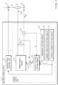
FIG. 1 is a schematic diagram illustrating a configuration example of an arc welding device according toEmbodiment 1; -
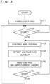
FIG. 2 is a flowchart illustrating a procedure of an arc welding method according toEmbodiment 1; -
FIG. 3 is a side section view illustrating a base material to be welded; -
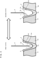
FIG. 4 is a schematic view illustrating how droplet is transferred by periodically varying welding current; -
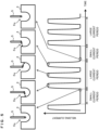
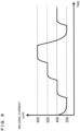
FIG. 5 is a graph illustrating a variation of welding current according toEmbodiment 1; -
FIG. 6 is a graph illustrating a variation of welding current according to a comparative example; -
FIG. 7 is a graph illustrating a variation of welding current according toEmbodiment 2; -
FIG. 8 is a graph illustrating a variation of welding current according to Embodiment 3; -
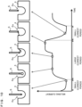
FIG. 9 is a graph illustrating a value of welding current according to an example in Embodiment 3; and -
FIG. 10 is a graph illustrating a variation of welding current according toEmbodiment 4. - The present invention will be described below in detail with reference to the drawings illustrating the embodiments thereof.
-
FIG. 1 is a schematic diagram illustrating a configuration example of an arc welding device according toEmbodiment 1. The arc welding device according toEmbodiment 1 is a gas shield arc welding machine of a consumable electrode type that is capable of butt welding abase material 4 having a plate thickness of 9mm to 30mm by a single pass. In particular, the arc welding device according toEmbodiment 1 is to control welding current Iw so as to move up and down the position of atip end 5a of awelding wire 5 inserted into a buriedspace 6a (seeFIG. 4 ) and to perform droplet transfer multiple times during the course of shifting of the position of thetip end 5a ofwelding wire 5 from a low state to a high state, thereby making it possible to suppress the occurrence of sputter while stably maintaining the buriedspace 6a. - The arc welding device according to
Embodiment 1 includes awelding power supply 1, atorch 2 and a wire feeding part 3. - The
torch 2 is made of conductive material such as copper alloy, and has a cylindrical contact chip which guides thewelding wire 5 to a to-be-welded portion of thebase material 4 while supplying welding current Iw required to generate arc 7 (seeFIG. 4 ). The contact chip makes contact with thewelding wire 5 penetrating into the contact chip, and supplies welding current Iw to thewelding wire 5. Moreover, thetorch 2 has a hollow cylindrical shape surrounding the contact chip, and has a nozzle for spraying shield gas to a portion to be welded. The shield gas is to prevent oxidation of thebase material 4 melted by thearc 7 as well as thewelding wire 5. The shield gas is, for example, carbon dioxide gas, mixed gas containing carbon dioxide gas and argon gas, or inert gas such as argon. - The
welding wire 5 is, for example, solid wire having a diameter of 0.9 mm to 1.6 mm, and functions as a consumable electrode. Thewelding wire 5 is, for example, a pack wire accommodated into a pail pack while being wound in a helical manner, or a reel wire wound around a wire reel. - The wire feeding part 3 includes a feed roller that feeds the
welding wire 5 to thetorch 2 and a motor that rotates the feed roller. The wire feeding part 3 rotates the feed roller to pull out thewelding wire 5 from a wire reel, and feeds the pulled-outwelding wire 5 to thetorch 2. Such a feeding method for thewelding wire 5 is a mere example, and is not particularly limited thereto. - The
welding power supply 1 is connected to the contact chip of thetorch 2 and thebase material 4 via power supply cables, and includes apower supply unit 11 that supplies welding current Iw and a feedingspeed control unit 12 that controls the feeding speed of thewelding wire 5. It is noted that thepower supply unit 11 and the feedingspeed control unit 12 may be formed in separate pieces. Thepower supply unit 11 includes apower supply circuit 11a that outputs PWM-controlled direct current, an outputvoltage setting circuit 11b, afrequency setting circuit 11c, a currentamplitude setting circuit 11d, an averagecurrent setting circuit 11e, avoltage detection unit 11f, acurrent detection unit 11g and acomparison circuit 11h. - The
voltage detection unit 11f detects welding voltage Vw, and outputs a voltage value signal Ed indicating the detected voltage value to thecomparison circuit 11h. - The
current detection unit 11g detects, for example, welding current Iw supplied from thewelding power supply 1 to thewelding wire 5 via thetorch 2 and flowing through thearc 7, and outputs a current value signal Id indicating the detected current value to the outputvoltage setting circuit 11b. - The
frequency setting circuit 11c outputs a frequency setting signal for setting a frequency for periodically varying the welding voltage Vw and welding current Iw between thebase material 4 and thewelding wire 5 to the outputvoltage setting circuit 11b. In the case of implementing the arc welding method according toEmbodiment 1, thefrequency setting circuit 11c outputs a frequency setting signal indicating a frequency in a range from 10Hz to 1000Hz, preferably from 50Hz to 300Hz, more preferably from 80Hz to 200Hz. - The current
amplitude setting circuit 11d outputs an amplitude setting signal for setting the amplitude of the welding current Iw which periodically varies, to the outputvoltage setting circuit 11b. The amplitude is a difference in current between the minimum current value and the maximum current value of varying welding current Iw. In the case of implementing the arc welding method according toEmbodiment 1, the currentamplitude setting circuit 11d outputs an amplitude setting signal indicating a current amplitude of 50A or larger, more preferably a current amplitude in the range from 100A to 500A, more preferably a current amplitude in the range from 200A to 400A. - The average
current setting circuit 11e outputs an average current setting signal for setting average current of periodically varying welding current Iw to the outputvoltage setting circuit 11b and the feedingspeed control unit 12. In the case of implementing the arc welding method according toEmbodiment 1, the averagecurrent setting circuit 11e outputs an average current setting signal indicating average current of 300A or larger, preferably average current in a range from 300A to 1000A, more preferably average current in a range from 500A to 800A. - The output
voltage setting circuit 11b generates an output voltage setting signal Ecr indicating rectangular wave-like target voltage so that the welding current Iw has a target frequency, a current amplitude and a target average current, based on the current value signal Id, frequency setting signal, amplitude setting signal and average current setting signal output from the respective units, and outputs the generated output voltage setting signal Ecr to thecomparison circuit 11h. - The
comparison circuit 11h compares the voltage value signal Ed output from thevoltage detection unit 11f with the output voltage setting signal Ecr output from the outputvoltage setting circuit 11b, and outputs a differential signal Ev indicating the difference between the signals to thepower supply circuit 11a. - The
power supply circuit 11a includes, for example, an AC-DC converter performing AC-DC conversion on commercial alternate current, an inverter circuit converting direct current subjected to AC-DC conversion into required alternate current by switching, and a rectification circuit rectifying the alternate current obtained by conversion. Thepower supply circuit 11a performs PWM control on the inverter in accordance with the differential signal Ev output from thecomparison circuit 11h, and outputs voltage to thewelding wire 5. As a result, welding voltage Vw that varies periodically is applied between the base material A and thewelding wire 5, and the welding current Iw flows. Thewelding power supply 1 is configured to receive an output instruction signal input from the outside via a control communication line (not illustrated), and thepower supply unit 11 starts supplying the welding current Iw to thepower supply circuit 11a using the output instruction signal as a trigger. The output instruction signal is, for example, output from a welding robot to thewelding power supply 1. Moreover, in the case of a manual welding machine, the output instruction signal is output to thewelding power supply 1 from thetorch 2 side when a hand operation switch located on thetorch 2 side is operated. -
FIG. 2 is a flowchart illustrating a procedure of an arc welding method according toEmbodiment 1.FIG. 3 is a side section view illustrating abase material 4 to be welded. First, a pair of base materials A to be joined by welding are placed at the arc welding device, and various settings for thewelding power supply 1 are performed (step S11). More specifically, a planarfirst base material 41 and a planarsecond base material 42 are prepared and arranged at predetermined welding work positions while end faces 41a and 42a that are to be welded are butted with each other. The first andsecond base materials - The
power supply device 1 then sets the welding condition of welding current Iw within a range at the frequency from 10Hz to 1000Hz, the average current of 300A or larger and the current amplitude of 50A or higher. - It is noted that the condition for welding current Iw may totally be set by a welding worker, or the
welding power supply 1 may accept the implementation of a welding method according toEmbodiment 1 to automatically set all conditions. Furthermore, thewelding power supply 1 may accept a part of the welding conditions such as average current through the operation unit and determine the rest of the welding conditions conforming to the accepted part of welding conditions so as to semi-automatically set the conditions. - After various settings are performed, the
welding power supply 1 determines whether or not the condition for starting output of the welding current Iw is satisfied (step S12). More specifically, thewelding power supply 1 determines whether or not an output instruction signal for welding is input. If it is determined that no output instruction signal is input and the output starting condition of welding current Iw is not satisfied (step S12: NO), thewelding power supply 1 waits in the state of waiting input of an output instruction signal. - If it is determined that the condition for starting welding current Iw is satisfied (step S12: YES), the feeding
speed control unit 12 of thewelding power supply 1 outputs to the wire feeding part 3 a feed control signal for instructing to feed wire, so that thewelding wire 5 is fed at a predetermined speed (step S13). The feeding speed of thewelding wire 5 is set within the range of, for example, approximately 5 to 100 meters per minute. The feedingspeed control unit 12 decides the feeding speed in accordance with the average current setting signal output from the averagecurrent setting circuit 11e. It is noted that the feeding speed ofwelding wire 5 may be at a constant speed or may be varied periodically. It may also be configured that a welding worker may directly set the feeding speed of wire. - Subsequently, the
power supply unit 11 of thewelding power supply 1 detects welding voltage Vw and welding current Iw at thevoltage detection unit 11f and thecurrent detection unit 11g (step S14), and performs PWM control so that the frequency, current amplitude and average current for the detected welding current Iw correspond to the set welding conditions and the welding current Iw periodically varies (step S15). - Subsequently, the
power supply unit 11 of thewelding power supply 1 determines whether or not the output of welding current Iw is stopped (step S16). More specifically, thewelding power supply 1 determines whether or not an input of the output instruction signal continues. If it is determined that the input of the output instruction signal continues and the output of welding current Iw is not stopped (step S16: NO), thepower supply unit 11 returns the processing to step S13 and continues outputting welding current Iw. - If it is determined that the output of the welding current Iw is stopped (step S16: YES), the
power supply unit 11 returns the processing to step S12. - Periodical variation of welding current Iw and droplet transfer will be summarized below.
- In the arc welding method according to
Embodiment 1, thepower supply unit 11 controls the welding current Iw such that the frequency thereof ranges from 10Hz to 1000Hz, the average current is 300A or larger and the current amplitude is 50A or higher. - Preferably, the
power supply unit 11 controls the welding current Iw such that the frequency thereof ranges from 50Hz to 300Hz, the average current ranges from 300A to 1000A, and the current amplitude ranges from 100A to 500A. -
FIG. 4 is a schematic view illustrating how droplet is transferred by periodically varying welding current Iw. If the welding current Iw is periodically varied under such welding conditions, a concave melted portion 6 is formed at thebase material 4, which is made of the molten metal of thewelding wire 5 and thebase material 4 melted by the heat ofarc 7 generated between thetip end 5a of thewelding wire 5 and a to-be-welded portion. Thearc 7 is photographed with a high-speed camera, to find that its state is periodically changed between the first state where thearc 7 is generated between thetip end 5a of thewelding wire 5 and abottom part 61 of the melted portion 6, and the second state where thearc 7 is generated between thetip end 5a and aside part 62 of the melted portion 6. - More specifically, the state is repeatedly switched between the first state where the
arc 7 is directed from the tip end of the welding wire W to thebottom part 61 of the melted portion 6 and the second state where thearc 7 is directed from thetip end 5a of thewelding wire 5 to aside part 62 of the melted portion 6. A small current period with a small average value of welding current Iw corresponds to the first state whereas a large current period with a large average value of welding current Iw corresponds to the second state. The first state is a state where the droplet transfer for thewelding wire 5 takes a form of drop transfer. The second state is a state where, for example, the droplet transfer for thewelding wire 5 takes a form of rotating transfer or pendulum transfer. - The drop transfer is an example of a form where droplet is transferred from the
tip end 5a ofwelding wire 5 to thebottom part 61 of the melted portion 6, whereas the rotating transfer is an example of a form where droplet is transferred from thetip end 5a ofwelding wire 5 to theside part 62 of the melted portion 6. Furthermore, the pendulum transfer is a characteristic form of droplet transfer where the liquid column andarc 7 formed at thetip end 5a ofwelding wire 5 is oscillated in pendulum on the same plane while the plane gradually rotates as a whole with its central axis corresponding to the protruding direction ofwelding wire 5. - Although the molten metal tends to flow in the direction in which the buried
space 6a is closed and thetip end 5a of thewelding wire 5 is buried, thearc 7 jumps to theside part 62 of the melted portion 6 in the second state, the molten metal of the melted portion 6 is pushed back in the direction of being separated from thewelding wire 5, and thus the buriedspace 6a is stabilized in a concave state. In the right view inFIG. 4 , as a result of droplet transfer at thetip end 5a of thewelding wire 5 melted due to large current, thetip end 5a ofwelding wire 5 is shortened. - The first state and the second state are switched from each other at a frequency ranging from 80Hz to 200Hz, which allows micro vibration of molten metal to occur at a frequency higher than the large corrugation frequency, suppressing corrugation formed on the molten metal.
- Now, control of welding current Iw and droplet transfer will be described in detail below.
-
FIG. 5 is a graph illustrating a variation of welding current Iw according toEmbodiment 1. The horizontal axis of the graph indicates time, whereas the vertical axis thereof indicates welding current Iw. Moreover, above the graph, a procedure of droplet transfer associated with the change in welding current Iw is schematically illustrated. Each schematic view illustrates the state ofwelding wire 5 and droplet transfer when the welding current Iw indicated by a dot circle is being supplied. Likewise, the schematic views inFIGS. 6 ,7 ,8 and10 described below also illustrate the state ofwelding wire 5 and droplet transfer. - In
Embodiment 1, thepower supply unit 11 controls the welding current Iw in the large current period such that droplet transfer from thetip end 5a ofwelding wire 5 to theside part 62 of the melted portion 6 is performed multiple times. More specifically, thepower supply unit 11 controls welding current Iw such that pulsed large current is supplied multiple times during the large current period as illustrated inFIG. 5 . For example, thepower supply unit 11 supplies pulsed large current three times in the large current period. The magnitude of pulsed current is approximately the same for each time. The welding current Iw in the small current period is 200A, for example, whereas pulsed large current in the large current period is 800A, for example. - In the small current period, as illustrated in the leftmost schematic view in
FIG. 5 , thetip end 5a ofwelding wire 5 is deeply inserted into the buriedspace 6a, and thearc 7 is directed to thebottom part 61 of the melted portion 6. When thearc 7 is directed to thebottom part 61 of the melted portion 6, deep penetration may be obtained. - In the large current period, as illustrated in three schematic views in the middle of
FIG. 5 , droplet transfer is performed little by little from thetip end 5a ofwelding wire 5 to theside part 62 of the melted portion 6 to shift the state of the wire tip position from a state where the position is low to a state where the position is high. In the case where thetip end 5a ofwelding wire 5 is at a high position, thearc 7 is directed to theside part 62 of the melted portion 6 and thus the buriedspace 6a is stabilized. Since droplet transfer is performed little by little, the occurrence of sputter may effectively be suppressed. - When alternated with the small current period again, the state of wire is changed from the state where the position of the wire tip end is high to the state where the position is low, as illustrated in the rightmost and leftmost schematic views in
FIG. 5 . - Thereafter, the state change is repeatedly performed. By varying the welding current Iw as described above, in the buried arc welding, deep penetration may be obtained while the buried
space 6a is stably maintained, and also the occurrence of sputter may be suppressed, allowing for stable one pass penetration welding of a thick plate. -
FIG. 6 is a graph illustrating a variation of welding current Iw according to a comparative example. The horizontal axis of the graph indicates time, whereas the vertical axis thereof indicates welding current Iw. Moreover, above the graph, a procedure of droplet transfer associated with the change in welding current Iw is schematically illustrated. - In the comparison example, the large current period has the same length as the small current period, and required large current is supplied at a time steadily in the large current period. In the state where the
tip end 5a ofwelding wire 5 is inserted into the buriedspace 6a, if the welding current Iw is rapidly increased and large current is supplied at a time, thewelding wire 5 is rapidly melted resulting in formation of a long liquid column and a large droplet is transferred in the vicinity of the opening of the buriedspace 6a, as illustrated in the two schematic views in the middle ofFIG. 6 . In the drawing, at the time point indicated by the broken star, short-circuit occurs in thewelding wire 5 and the melted portion 6, which thus generates large sputter particles. - As can be seen from the comparison between
FIG. 5 andFIG. 6 , in the large current period, pulsed large current is supplied multiple times to shift the droplets little by little, which can suppress the occurrence of sputter. - Accordingly, with the arc welding method and arc welding device according to
Embodiment 1 configured as described above, in the buried arc welding using large current of 300A or larger, the occurrence of sputter may be suppressed while stably maintaining the buriedspace 6a, allowing for stable single pass penetration welding of a thick plate. - Moreover, even if buried arc welding is performed using large current of 300A or higher, corrugation of molten metal may be suppressed by periodically varying welding current Iw, which can prevent disturbance and drooping of a bead from occurring.
- As the arc welding method and the arc welding device according to
Embodiment 2 are different from those inEmbodiment 1 for the method of controlling welding current Iw, the difference will mainly be described below. Since the other configurations and effects are similar to those inEmbodiment 1, corresponding parts are denoted by similar reference codes and detailed description thereof will not be repeated. -
FIG. 7 is a graph illustrating a variation of welding current Iw according toEmbodiment 2. The horizontal axis of the graph indicates time, whereas the vertical axis thereof indicates welding current Iw. Moreover, above the graph, a procedure of droplet transfer associated with the change in welding current Iw is schematically illustrated. - In
Embodiment 2, thepower supply unit 11 performs control such that the large current period is longer than the small current period, and the welding current Iw in the large current period is constant. The length and current value of the large current period are a period and current value in which droplet transfer may be performed multiple times in the large current period. The welding current Iw in the small current period is 200A, whereas the welding current Iw in the large current period is 500A, for example. - With the arc welding method and arc welding device according to
Embodiment 2 configured as described above, droplet transfer of thewelding wire 5 may gradually be performed, which can reduce the length of a liquid column and suppress the occurrence of sputter. Accordingly, in the buried arc welding, the occurrence of sputter may be suppressed while stably maintaining the buriedspace 6a, allowing for stable single pass penetration welding of a thick plate. - As the arc welding method and the arc welding device according to Embodiment 3 are different from those in
Embodiment 1 for the method of controlling welding current Iw, the difference will mainly be described below. Since the other configurations and effects are similar to those inEmbodiment 1, corresponding parts are denoted by similar reference codes and detailed description thereof will not be repeated. -
FIG. 8 is a graph illustrating a variation of welding current Iw according to Embodiment 3. The horizontal axis of the graph indicates time, whereas the vertical axis thereof indicates welding current Iw. Moreover, above the graph, a procedure of droplet transfer associated with the change in welding current Iw is schematically illustrated. - In Embodiment 3, the
power supply unit 11 controls the output of the welding current Iw so that the welding current Iw is increased step by step in the large current period. For example, thepower supply unit 11 increases the welding current Iw in three stages until it reaches the maximum welding current Iw, as illustrated inFIG. 8 . The period during which required welding current Iw is output in each stage has substantially the same length as well as substantially the same amount of increase in the welding current Iw. - Buried arc welding of the
base material 4 is performed under such welding conditions that thewelding wire 5 has a diameter of 1.2mm, thewelding power supply 1 has a feeding speed ofwelding wire 5 at 40minutes per minute, the average current of welding current Iw of 540A and the average voltage of 51V. -
FIG. 9 is a graph illustrating the value of the welding current Iw according to an example. The horizontal axis of the graph indicates time, whereas the vertical axis thereof indicates welding current Iw. As illustrated inFIG. 9 , thewelding power supply 1 supplies the welding current Iw of 200A during a small current period and supplies the welding current Iw of 400A, 600A and 800A that increases in three stages during a large current period. The frequency in which a unit waveform including the small current period and the large current period is repeated corresponds to 100Hz. Since droplet transfer occurs once at each of the stages where the welding current Iw is increased during the large current period, the position of the tip of thewelding wire 5 may be pulled up while suppressing formation of a long liquid column in thewelding wire 5, which thus can stabilize the buriedspace 6a. - With the arc welding method and arc welding device according to Embodiment 3 configured as described above, in the buried arc welding, the occurrence of sputter may be suppressed while stably maintaining the buried
space 6a, allowing for stable single pass penetration welding of a thick plate. - As the arc welding method and the arc welding device according to
Embodiment 4 are different fromEmbodiment 1 in the method of controlling welding current Iw, the difference will mainly be described below. Since the other configurations and effects are similar to those inEmbodiment 1, corresponding parts are denoted by similar reference codes and detailed description thereof will not be repeated. -
FIG. 10 is a graph illustrating a variation of welding current Iw according toEmbodiment 4. The horizontal axis of the graph indicates time, whereas the vertical axis thereof indicates welding current Iw. Moreover, above the graph, a procedure of droplet transfer associated with the change in welding current Iw is schematically illustrated. - In
Embodiment 4, thepower supply unit 11 controls the output of the welding current Iw so that the welding current Iw is increased step by step in the large current period. For example, thepower supply unit 11 increases the welding current Iw in two stages until it reaches the maximum welding current Iw, as illustrated inFIG. 10 . The former stage is longer than the latter stage, and the amount of increase in the welding current Iw in the former stage is larger than the amount of increase in the welding current Iw in the latter stage. Specifically, the period of the former stage is approximately twice as long as the latter stage, and the amount of increase in the welding current Iw in the former stage is approximately twice as the amount of the welding current Iw increased from the former stage to the latter stage. - In the state where the
tip end 5a of thewelding wire 5 is inserted into the buriedspace 6a deeply or to a middle part, no sputter occurs even if the liquid column is long. Thewelding wire 5 is thus melted such that, when thetip end 5a ofwelding wire 5 is pulled up from a lower part to an upper part of the buriedspace 6a, thewelding wire 5 is relatively rapidly melted for droplet transfer in an earlier stage and then increases the welding current Iw to further generate a small amount of droplet transfer, thereby more efficiently pulling up thewelding wire 5. - With the arc welding method and arc welding device according to
Embodiment 4 configured as described above, in the buried arc welding, the occurrence of sputter may be suppressed while stably maintaining the buriedspace 6a, allowing for stable single pass penetration welding of a thick plate. - It should be understood that the embodiments disclosed herein are illustrative and non-restrictive in every respect. Since the scope of the present invention is defined by the appended claims rather than by the description preceding them, all changes that fall within metes and bounds of the claims, or equivalence of such metes and bounds thereof are therefore intended to be embraced by the claims.
-
- 1 welding power supply
- 2 torch
- 3 wire feeding unit
- 4 base material
- 5 welding wire
- 5a tip end
- 6 melted portion
- 6a buried space
- 61 bottom part
- 62 side part
- 7 arc
- 11 power supply unit
- 11a power supply circuit
- 11b output voltage setting circuit
- 11c frequency setting circuit
- 11d current amplitude setting circuit
- 11e average current setting circuit
- 11f voltage detection unit
- 11g current detection unit
- 11h comparison circuit
- 12 feeding speed control unit
- 41 first base material
- 42 second base material
- Vw welding voltage
- Iw welding current
- Ecr output voltage setting signal
- Ed voltage value signal
- Id current value signal
- Ev differential signal
Claims (7)
- An arc welding method feeding welding wire (5) to a base material (4) while supplying welding current having average current of 300A or larger, comprising:
feeding the welding wire (5) at a speed of a tip end (5a) of the welding wire (5) being inserted into a space (6a) of a concave melted portion (6) formed in the base material (4) by the arc generated between the tip end (5a) and the base material (4),characterized in that the method comprises:periodically alternating a small current period where the welding current has a small average value and droplet is transferred from the tip end (5a) to a bottom part (61) of the melted portion (6), and a large current period where the welding current has a large average value and droplet is transferred from the tip end (5a) to a side part (62) of the melted portion (6); andcontrolling the welding current in the large current period so that droplet is transferred from the tip end (5a) to the side part (62) a plurality of times in each large current period. - The arc welding method according to claim 1, wherein a plurality of pulsed currents are supplied in each large current period.
- The arc welding method according to claim 1, wherein the large current period is longer than the small current period, and the welding current in the large current period is constant.
- The arc welding method according to claim 1, wherein the welding current is increased step by step in the large current period.
- The arc welding method according to claim 4, wherein a current difference between the maximum welding current in the large current period and the welding current in a previous stage of a stage where the maximum welding current is supplied is smaller than a current difference between the welding current in the small current period and the welding current in the previous stage.
- The arc welding method according to any one of claims 1 to 5, wherein the large current period and the small current period are alternated at a frequency in a range from 10Hz to 1000Hz.
- An arc welding device including a wire feeding part (3) configured to feed welding wire (5) to a base material (4), and a power supply unit (11) configured to supply welding current having average current of 300A or larger, whereinthe wire feeding part (3) configured to feed the welding wire (5) at a speed of a tip end (5a) of the welding wire (5) being inserted into a space (6a) of a concave melted portion (6) formed in the base material (4) by the arc generated between the tip end (5a) and the base material (4),characterized in that:
the power supply unit (11) is configured to control the welding current and thereby periodically alternates a small current period where the welding current has a small average value and droplet is transferred from the tip end (5a) to a bottom part (61) of the melted portion (6), and a large current period where the welding current has a large average value and droplet is transferred from the tip end (5a) to a side part (62) of the melted portion (6), and is configured to control the welding current in the large current period so that droplet is transferred from the tip end (5a) to the side part (62) a plurality of times in each large current period.
Applications Claiming Priority (2)
| Application Number | Priority Date | Filing Date | Title |
|---|---|---|---|
| JP2016236944 | 2016-12-06 | ||
| PCT/JP2017/043442 WO2018105548A1 (en) | 2016-12-06 | 2017-12-04 | Arc welding method and arc welding device |
Publications (3)
| Publication Number | Publication Date |
|---|---|
| EP3552748A1 EP3552748A1 (en) | 2019-10-16 |
| EP3552748A4 EP3552748A4 (en) | 2020-09-02 |
| EP3552748B1 true EP3552748B1 (en) | 2023-09-13 |
Family
ID=62491093
Family Applications (1)
| Application Number | Title | Priority Date | Filing Date |
|---|---|---|---|
| EP17878292.6A Active EP3552748B1 (en) | 2016-12-06 | 2017-12-04 | Arc welding method and arc welding device |
Country Status (6)
| Country | Link |
|---|---|
| US (1) | US11407054B2 (en) |
| EP (1) | EP3552748B1 (en) |
| JP (1) | JP6959941B2 (en) |
| KR (1) | KR102324216B1 (en) |
| CN (1) | CN110023021B (en) |
| WO (1) | WO2018105548A1 (en) |
Families Citing this family (4)
| Publication number | Priority date | Publication date | Assignee | Title |
|---|---|---|---|---|
| EP3342523B1 (en) * | 2015-08-25 | 2023-05-03 | Daihen Corporation | Welding methods and arc welding device |
| KR102237436B1 (en) * | 2016-03-11 | 2021-04-07 | 가부시키가이샤 다이헨 | Arc welding system and wire feeding device |
| CN108890082B (en) * | 2018-07-19 | 2020-07-24 | 唐山松下产业机器有限公司 | Arc welding control method and device, and welding equipment |
| JP7475218B2 (en) * | 2019-12-25 | 2024-04-26 | 株式会社ダイヘン | Arc welding method and arc welding device |
Family Cites Families (15)
| Publication number | Priority date | Publication date | Assignee | Title |
|---|---|---|---|---|
| US6025573A (en) * | 1998-10-19 | 2000-02-15 | Lincoln Global, Inc. | Controller and method for pulse welding |
| JP2000263228A (en) * | 1999-03-18 | 2000-09-26 | Hitachi Zosen Corp | Selecting method for welding condition |
| JP4002960B2 (en) * | 2000-02-29 | 2007-11-07 | 独立行政法人物質・材料研究機構 | Consumable electrode gas shield arc welding method and apparatus |
| CN1199760C (en) * | 2003-01-16 | 2005-05-04 | 中国重型汽车集团有限公司 | Technique for welding car axle housing made by punching medium heavy steel plates |
| AT413953B (en) * | 2003-11-25 | 2006-07-15 | Fronius Int Gmbh | METHOD AND CIRCUIT FOR TOUCH-FREE IGNITION OF A WELDING ARC |
| DE102005024802A1 (en) * | 2005-05-27 | 2006-11-30 | Ewm Hightec Welding Gmbh | Welding current source and method for MIG / MAG welding |
| JP4498263B2 (en) * | 2005-11-08 | 2010-07-07 | 株式会社神戸製鋼所 | Pulse arc welding method |
| JP2007229775A (en) | 2006-03-02 | 2007-09-13 | Daihen Corp | Consumable electrode arc welding method |
| US9352410B2 (en) * | 2013-03-15 | 2016-05-31 | Lincoln Global, Inc. | System for and method of narrow-groove joining of metals |
| US10543551B2 (en) * | 2013-09-16 | 2020-01-28 | Illinois Tool Works Inc. | Synchronized rotating arc welding method and system |
| US11224929B2 (en) * | 2014-02-24 | 2022-01-18 | Daihen Corporation | Arc welding method |
| CN107107233B (en) * | 2014-10-17 | 2019-05-17 | 松下知识产权经营株式会社 | The control method of arc welding |
| JP6777969B2 (en) * | 2016-02-18 | 2020-10-28 | 株式会社ダイヘン | Arc welding method and arc welding equipment |
| EP3342523B1 (en) * | 2015-08-25 | 2023-05-03 | Daihen Corporation | Welding methods and arc welding device |
| WO2018043626A1 (en) * | 2016-09-05 | 2018-03-08 | パナソニックIpマネジメント株式会社 | Arc welding control method |
-
2017
- 2017-12-04 JP JP2018554985A patent/JP6959941B2/en active Active
- 2017-12-04 CN CN201780073640.7A patent/CN110023021B/en active Active
- 2017-12-04 WO PCT/JP2017/043442 patent/WO2018105548A1/en unknown
- 2017-12-04 EP EP17878292.6A patent/EP3552748B1/en active Active
- 2017-12-04 US US16/463,120 patent/US11407054B2/en active Active
- 2017-12-04 KR KR1020197014863A patent/KR102324216B1/en active IP Right Grant
Also Published As
| Publication number | Publication date |
|---|---|
| JPWO2018105548A1 (en) | 2019-10-24 |
| US11407054B2 (en) | 2022-08-09 |
| KR20190092395A (en) | 2019-08-07 |
| EP3552748A4 (en) | 2020-09-02 |
| KR102324216B1 (en) | 2021-11-09 |
| CN110023021B (en) | 2021-08-03 |
| US20190283165A1 (en) | 2019-09-19 |
| WO2018105548A1 (en) | 2018-06-14 |
| JP6959941B2 (en) | 2021-11-05 |
| CN110023021A (en) | 2019-07-16 |
| EP3552748A1 (en) | 2019-10-16 |
Similar Documents
| Publication | Publication Date | Title |
|---|---|---|
| EP3552748B1 (en) | Arc welding method and arc welding device | |
| US9050677B2 (en) | Arc welding method and arc welding apparatus | |
| EP3208024B1 (en) | Arc welding control method | |
| JP4807479B2 (en) | Arc welding control method and arc welding apparatus | |
| JP6596669B2 (en) | Control method of arc welding | |
| JP6777969B2 (en) | Arc welding method and arc welding equipment | |
| EP3412396B1 (en) | Pulsed arc welding control method and pulsed arc welding device | |
| WO2017029783A1 (en) | Arc welding control method | |
| JP6748555B2 (en) | Arc welding method and arc welding apparatus | |
| WO2017033978A1 (en) | Welding method and arc welding device | |
| WO2017038060A1 (en) | Arc welding method and arc welding device | |
| JP6994623B2 (en) | Arc start method | |
| JP2013527037A (en) | Short-circuit arc welding system | |
| JP7222810B2 (en) | Arc welding device and arc welding method | |
| JP2013169555A (en) | Arc welding control method and arc welding equipment | |
| CN109693016B (en) | Arc welding device and arc welding method | |
| JP2022033399A (en) | Weld power supply, weld system, control method of weld power supply and program | |
| JP6748556B2 (en) | Arc welding method and arc welding apparatus | |
| JP7475218B2 (en) | Arc welding method and arc welding device | |
| JP2018069332A (en) | Arc-welding method | |
| CN115461178A (en) | DC arc welding control method | |
| JP2022030719A (en) | Arc welding method and arc welding equipment | |
| JP2022144100A (en) | Arc-welding device and arc-welding method |
Legal Events
| Date | Code | Title | Description |
|---|---|---|---|
| STAA | Information on the status of an ep patent application or granted ep patent |
Free format text: STATUS: THE INTERNATIONAL PUBLICATION HAS BEEN MADE |
|
| PUAI | Public reference made under article 153(3) epc to a published international application that has entered the european phase |
Free format text: ORIGINAL CODE: 0009012 |
|
| STAA | Information on the status of an ep patent application or granted ep patent |
Free format text: STATUS: REQUEST FOR EXAMINATION WAS MADE |
|
| 17P | Request for examination filed |
Effective date: 20190612 |
|
| AK | Designated contracting states |
Kind code of ref document: A1 Designated state(s): AL AT BE BG CH CY CZ DE DK EE ES FI FR GB GR HR HU IE IS IT LI LT LU LV MC MK MT NL NO PL PT RO RS SE SI SK SM TR |
|
| AX | Request for extension of the european patent |
Extension state: BA ME |
|
| DAV | Request for validation of the european patent (deleted) | ||
| DAX | Request for extension of the european patent (deleted) | ||
| A4 | Supplementary search report drawn up and despatched |
Effective date: 20200731 |
|
| RIC1 | Information provided on ipc code assigned before grant |
Ipc: B23K 9/073 20060101ALI20200727BHEP Ipc: B23K 9/095 20060101AFI20200727BHEP Ipc: B23K 9/173 20060101ALI20200727BHEP Ipc: B23K 9/09 20060101ALI20200727BHEP |
|
| GRAP | Despatch of communication of intention to grant a patent |
Free format text: ORIGINAL CODE: EPIDOSNIGR1 |
|
| STAA | Information on the status of an ep patent application or granted ep patent |
Free format text: STATUS: GRANT OF PATENT IS INTENDED |
|
| RIC1 | Information provided on ipc code assigned before grant |
Ipc: B23K 9/073 20060101ALI20230424BHEP Ipc: B23K 9/173 20060101ALI20230424BHEP Ipc: B23K 9/09 20060101ALI20230424BHEP Ipc: B23K 9/095 20060101AFI20230424BHEP |
|
| INTG | Intention to grant announced |
Effective date: 20230517 |
|
| GRAS | Grant fee paid |
Free format text: ORIGINAL CODE: EPIDOSNIGR3 |
|
| GRAA | (expected) grant |
Free format text: ORIGINAL CODE: 0009210 |
|
| STAA | Information on the status of an ep patent application or granted ep patent |
Free format text: STATUS: THE PATENT HAS BEEN GRANTED |
|
| AK | Designated contracting states |
Kind code of ref document: B1 Designated state(s): AL AT BE BG CH CY CZ DE DK EE ES FI FR GB GR HR HU IE IS IT LI LT LU LV MC MK MT NL NO PL PT RO RS SE SI SK SM TR |
|
| REG | Reference to a national code |
Ref country code: GB Ref legal event code: FG4D |
|
| REG | Reference to a national code |
Ref country code: CH Ref legal event code: EP |
|
| REG | Reference to a national code |
Ref country code: DE Ref legal event code: R096 Ref document number: 602017074281 Country of ref document: DE |
|
| REG | Reference to a national code |
Ref country code: IE Ref legal event code: FG4D |
|
| REG | Reference to a national code |
Ref country code: LT Ref legal event code: MG9D |
|
| REG | Reference to a national code |
Ref country code: NL Ref legal event code: MP Effective date: 20230913 |
|
| PG25 | Lapsed in a contracting state [announced via postgrant information from national office to epo] |
Ref country code: GR Free format text: LAPSE BECAUSE OF FAILURE TO SUBMIT A TRANSLATION OF THE DESCRIPTION OR TO PAY THE FEE WITHIN THE PRESCRIBED TIME-LIMIT Effective date: 20231214 |
|
| PG25 | Lapsed in a contracting state [announced via postgrant information from national office to epo] |
Ref country code: SE Free format text: LAPSE BECAUSE OF FAILURE TO SUBMIT A TRANSLATION OF THE DESCRIPTION OR TO PAY THE FEE WITHIN THE PRESCRIBED TIME-LIMIT Effective date: 20230913 Ref country code: RS Free format text: LAPSE BECAUSE OF FAILURE TO SUBMIT A TRANSLATION OF THE DESCRIPTION OR TO PAY THE FEE WITHIN THE PRESCRIBED TIME-LIMIT Effective date: 20230913 Ref country code: NO Free format text: LAPSE BECAUSE OF FAILURE TO SUBMIT A TRANSLATION OF THE DESCRIPTION OR TO PAY THE FEE WITHIN THE PRESCRIBED TIME-LIMIT Effective date: 20231213 Ref country code: LV Free format text: LAPSE BECAUSE OF FAILURE TO SUBMIT A TRANSLATION OF THE DESCRIPTION OR TO PAY THE FEE WITHIN THE PRESCRIBED TIME-LIMIT Effective date: 20230913 Ref country code: LT Free format text: LAPSE BECAUSE OF FAILURE TO SUBMIT A TRANSLATION OF THE DESCRIPTION OR TO PAY THE FEE WITHIN THE PRESCRIBED TIME-LIMIT Effective date: 20230913 Ref country code: HR Free format text: LAPSE BECAUSE OF FAILURE TO SUBMIT A TRANSLATION OF THE DESCRIPTION OR TO PAY THE FEE WITHIN THE PRESCRIBED TIME-LIMIT Effective date: 20230913 Ref country code: GR Free format text: LAPSE BECAUSE OF FAILURE TO SUBMIT A TRANSLATION OF THE DESCRIPTION OR TO PAY THE FEE WITHIN THE PRESCRIBED TIME-LIMIT Effective date: 20231214 Ref country code: FI Free format text: LAPSE BECAUSE OF FAILURE TO SUBMIT A TRANSLATION OF THE DESCRIPTION OR TO PAY THE FEE WITHIN THE PRESCRIBED TIME-LIMIT Effective date: 20230913 |
|
| PGFP | Annual fee paid to national office [announced via postgrant information from national office to epo] |
Ref country code: DE Payment date: 20230928 Year of fee payment: 7 |
|
| REG | Reference to a national code |
Ref country code: AT Ref legal event code: MK05 Ref document number: 1610767 Country of ref document: AT Kind code of ref document: T Effective date: 20230913 |
|
| PG25 | Lapsed in a contracting state [announced via postgrant information from national office to epo] |
Ref country code: NL Free format text: LAPSE BECAUSE OF FAILURE TO SUBMIT A TRANSLATION OF THE DESCRIPTION OR TO PAY THE FEE WITHIN THE PRESCRIBED TIME-LIMIT Effective date: 20230913 |
|
| PG25 | Lapsed in a contracting state [announced via postgrant information from national office to epo] |
Ref country code: IS Free format text: LAPSE BECAUSE OF FAILURE TO SUBMIT A TRANSLATION OF THE DESCRIPTION OR TO PAY THE FEE WITHIN THE PRESCRIBED TIME-LIMIT Effective date: 20240113 |
|
| PG25 | Lapsed in a contracting state [announced via postgrant information from national office to epo] |
Ref country code: AT Free format text: LAPSE BECAUSE OF FAILURE TO SUBMIT A TRANSLATION OF THE DESCRIPTION OR TO PAY THE FEE WITHIN THE PRESCRIBED TIME-LIMIT Effective date: 20230913 |
|
| PG25 | Lapsed in a contracting state [announced via postgrant information from national office to epo] |
Ref country code: ES Free format text: LAPSE BECAUSE OF FAILURE TO SUBMIT A TRANSLATION OF THE DESCRIPTION OR TO PAY THE FEE WITHIN THE PRESCRIBED TIME-LIMIT Effective date: 20230913 |
|
| PG25 | Lapsed in a contracting state [announced via postgrant information from national office to epo] |
Ref country code: SM Free format text: LAPSE BECAUSE OF FAILURE TO SUBMIT A TRANSLATION OF THE DESCRIPTION OR TO PAY THE FEE WITHIN THE PRESCRIBED TIME-LIMIT Effective date: 20230913 Ref country code: RO Free format text: LAPSE BECAUSE OF FAILURE TO SUBMIT A TRANSLATION OF THE DESCRIPTION OR TO PAY THE FEE WITHIN THE PRESCRIBED TIME-LIMIT Effective date: 20230913 Ref country code: IS Free format text: LAPSE BECAUSE OF FAILURE TO SUBMIT A TRANSLATION OF THE DESCRIPTION OR TO PAY THE FEE WITHIN THE PRESCRIBED TIME-LIMIT Effective date: 20240113 Ref country code: ES Free format text: LAPSE BECAUSE OF FAILURE TO SUBMIT A TRANSLATION OF THE DESCRIPTION OR TO PAY THE FEE WITHIN THE PRESCRIBED TIME-LIMIT Effective date: 20230913 Ref country code: EE Free format text: LAPSE BECAUSE OF FAILURE TO SUBMIT A TRANSLATION OF THE DESCRIPTION OR TO PAY THE FEE WITHIN THE PRESCRIBED TIME-LIMIT Effective date: 20230913 Ref country code: CZ Free format text: LAPSE BECAUSE OF FAILURE TO SUBMIT A TRANSLATION OF THE DESCRIPTION OR TO PAY THE FEE WITHIN THE PRESCRIBED TIME-LIMIT Effective date: 20230913 Ref country code: AT Free format text: LAPSE BECAUSE OF FAILURE TO SUBMIT A TRANSLATION OF THE DESCRIPTION OR TO PAY THE FEE WITHIN THE PRESCRIBED TIME-LIMIT Effective date: 20230913 Ref country code: SK Free format text: LAPSE BECAUSE OF FAILURE TO SUBMIT A TRANSLATION OF THE DESCRIPTION OR TO PAY THE FEE WITHIN THE PRESCRIBED TIME-LIMIT Effective date: 20230913 Ref country code: PT Free format text: LAPSE BECAUSE OF FAILURE TO SUBMIT A TRANSLATION OF THE DESCRIPTION OR TO PAY THE FEE WITHIN THE PRESCRIBED TIME-LIMIT Effective date: 20240115 |