WO2018105236A1 - 電池パック - Google Patents
電池パック Download PDFInfo
- Publication number
- WO2018105236A1 WO2018105236A1 PCT/JP2017/037325 JP2017037325W WO2018105236A1 WO 2018105236 A1 WO2018105236 A1 WO 2018105236A1 JP 2017037325 W JP2017037325 W JP 2017037325W WO 2018105236 A1 WO2018105236 A1 WO 2018105236A1
- Authority
- WO
- WIPO (PCT)
- Prior art keywords
- battery cell
- battery
- battery pack
- holder
- substrate
- Prior art date
- Legal status (The legal status is an assumption and is not a legal conclusion. Google has not performed a legal analysis and makes no representation as to the accuracy of the status listed.)
- Ceased
Links
Images










Classifications
-
- H—ELECTRICITY
- H01—ELECTRIC ELEMENTS
- H01M—PROCESSES OR MEANS, e.g. BATTERIES, FOR THE DIRECT CONVERSION OF CHEMICAL ENERGY INTO ELECTRICAL ENERGY
- H01M50/00—Constructional details or processes of manufacture of the non-active parts of electrochemical cells other than fuel cells, e.g. hybrid cells
- H01M50/20—Mountings; Secondary casings or frames; Racks, modules or packs; Suspension devices; Shock absorbers; Transport or carrying devices; Holders
- H01M50/204—Racks, modules or packs for multiple batteries or multiple cells
- H01M50/207—Racks, modules or packs for multiple batteries or multiple cells characterised by their shape
- H01M50/211—Racks, modules or packs for multiple batteries or multiple cells characterised by their shape adapted for pouch cells
-
- H—ELECTRICITY
- H01—ELECTRIC ELEMENTS
- H01M—PROCESSES OR MEANS, e.g. BATTERIES, FOR THE DIRECT CONVERSION OF CHEMICAL ENERGY INTO ELECTRICAL ENERGY
- H01M50/00—Constructional details or processes of manufacture of the non-active parts of electrochemical cells other than fuel cells, e.g. hybrid cells
- H01M50/20—Mountings; Secondary casings or frames; Racks, modules or packs; Suspension devices; Shock absorbers; Transport or carrying devices; Holders
- H01M50/202—Casings or frames around the primary casing of a single cell or a single battery
-
- H—ELECTRICITY
- H01—ELECTRIC ELEMENTS
- H01M—PROCESSES OR MEANS, e.g. BATTERIES, FOR THE DIRECT CONVERSION OF CHEMICAL ENERGY INTO ELECTRICAL ENERGY
- H01M2220/00—Batteries for particular applications
- H01M2220/10—Batteries in stationary systems, e.g. emergency power source in plant
-
- H—ELECTRICITY
- H01—ELECTRIC ELEMENTS
- H01M—PROCESSES OR MEANS, e.g. BATTERIES, FOR THE DIRECT CONVERSION OF CHEMICAL ENERGY INTO ELECTRICAL ENERGY
- H01M2220/00—Batteries for particular applications
- H01M2220/20—Batteries in motive systems, e.g. vehicle, ship, plane
-
- H—ELECTRICITY
- H01—ELECTRIC ELEMENTS
- H01M—PROCESSES OR MEANS, e.g. BATTERIES, FOR THE DIRECT CONVERSION OF CHEMICAL ENERGY INTO ELECTRICAL ENERGY
- H01M2220/00—Batteries for particular applications
- H01M2220/30—Batteries in portable systems, e.g. mobile phone, laptop
-
- H—ELECTRICITY
- H01—ELECTRIC ELEMENTS
- H01M—PROCESSES OR MEANS, e.g. BATTERIES, FOR THE DIRECT CONVERSION OF CHEMICAL ENERGY INTO ELECTRICAL ENERGY
- H01M50/00—Constructional details or processes of manufacture of the non-active parts of electrochemical cells other than fuel cells, e.g. hybrid cells
- H01M50/20—Mountings; Secondary casings or frames; Racks, modules or packs; Suspension devices; Shock absorbers; Transport or carrying devices; Holders
- H01M50/284—Mountings; Secondary casings or frames; Racks, modules or packs; Suspension devices; Shock absorbers; Transport or carrying devices; Holders with incorporated circuit boards, e.g. printed circuit boards [PCB]
-
- Y—GENERAL TAGGING OF NEW TECHNOLOGICAL DEVELOPMENTS; GENERAL TAGGING OF CROSS-SECTIONAL TECHNOLOGIES SPANNING OVER SEVERAL SECTIONS OF THE IPC; TECHNICAL SUBJECTS COVERED BY FORMER USPC CROSS-REFERENCE ART COLLECTIONS [XRACs] AND DIGESTS
- Y02—TECHNOLOGIES OR APPLICATIONS FOR MITIGATION OR ADAPTATION AGAINST CLIMATE CHANGE
- Y02E—REDUCTION OF GREENHOUSE GAS [GHG] EMISSIONS, RELATED TO ENERGY GENERATION, TRANSMISSION OR DISTRIBUTION
- Y02E60/00—Enabling technologies; Technologies with a potential or indirect contribution to GHG emissions mitigation
- Y02E60/10—Energy storage using batteries
Definitions
- the present technology relates to a battery pack, and more particularly to a battery pack, a vehicle, a power storage system, a power tool, and an electronic device.
- a first plate-like portion and a second plate that are integrally coupled to both widthwise end portions of the first plate-like portion and extend in a substantially vertical direction with respect to both surfaces of the first plate-like portion.
- a battery protection member having a shape portion and a flat battery sealed with a film-like exterior material on the first plate shape portion, the first plate on the outer edge of the flat shape battery
- a battery pack characterized in that the vertical projection surface onto the shaped part is located inside the outer edge of the first plate-like part (see Patent Document 1).
- a battery cell that charges and discharges power an outer peripheral wall that surrounds an outer peripheral side surface of the battery cell, and a bracket that is provided inside the outer peripheral wall and has a support that supports the battery cell.
- Patent Document a battery unit in which two battery cells are inserted into the outer peripheral wall portion from the front side and the back side of the bracket and are attached to both surfaces of the support.
- the battery pack (battery unit) based on the techniques proposed in Patent Documents 1 and 2 may not be able to further improve battery characteristics and reliability. Therefore, the present condition is that the battery pack which improved the battery characteristic and reliability further is desired.
- the present technology has been made in view of such a situation, and provides a battery pack having excellent battery characteristics and excellent reliability, a vehicle including the battery pack, a power storage system, an electric tool, and an electronic device.
- the main purpose is to do.
- the present inventors have succeeded in developing a battery pack having excellent battery characteristics and excellent reliability, and have completed the present technology. .
- the battery cell is accommodated in the holder, and the holder has a plate-like member having a first placement surface on which the battery cell is placed; A first side member and a second side member that are substantially perpendicular to the first placement surface and extend to a side on which the battery cell is placed; the first side member and the second side member; Provided is a battery pack in which a length of a side member extending to a side on which the battery cell is placed is larger than a length of the battery cell in a substantially vertical direction with respect to the first placement surface.
- the battery pack may include a substrate, the substrate is accommodated in the holder, and the flat plate member has a second placement surface on which the substrate is placed on the back side of the first placement surface.
- At least a battery cell and a battery cell holder are provided, the battery cell is accommodated in the battery cell holder, and the battery cell holder has a first placement surface on which the battery cell is placed.
- the length of the side member and the second side member extending to the side on which the battery cell is placed is larger than the length of the battery cell in the direction substantially perpendicular to the first placement surface, and the flat plate
- the member has a second placement surface on which the battery cell is placed on the back side of the first placement surface, and the battery cell holder is substantially perpendicular to the second placement surface,
- a third side member and a fourth side member extending to the side where the battery cell is placed, the third side member and Length battery cell of the fourth sidewall member extends in the placed side is greater than the length of the substantially vertical direction with respect to the second mounting surface of the battery cell, to provide a battery pack.
- the battery pack further includes a substrate and a substrate holder, the substrate is accommodated in the substrate holder, and the substrate holder includes a flat member having a placement surface on which the substrate is placed. Good.
- the battery pack may be a battery pack in which the battery cell holder and the substrate holder are fixed in a substantially vertical direction with respect to a flat plate member included in the battery cell holder and a flat plate member included in the substrate holder.
- connection tab is provided, and the connection tab is connected to one electrode of the battery cell, and a second connection portion connected to the other electrode of the battery cell is an insulating member. It may be a battery pack having a structure integrated with a battery pack.
- connection member connected to the connection tab and the substrate, and the connection member has a length of the connection member in a direction substantially perpendicular to a connection direction of the connection tab, the connection member, and the substrate.
- a battery pack having a structure that gradually changes may be used.
- the battery cell provided in the battery pack according to the present technology may be a laminated battery.
- the holder and the battery cell may be fixed with an adhesive tape.
- the battery cell holder and the battery cell may be fixed with an adhesive tape.
- a battery pack according to the present technology a driving force conversion device that receives power supplied from the battery pack and converts the power into a driving force of the vehicle, a driving unit that drives according to the driving force, and a vehicle control device.
- a power storage device having a battery pack according to the present technology, a power consuming device to which power is supplied from the battery pack, a control device for controlling power supply from the battery pack to the power consuming device, and charging the battery pack
- Providing a power storage system comprising: Provided a power tool comprising: a battery pack according to the present technology; and a movable part to which electric power is supplied from the battery pack; Provided is an electronic device that includes a battery pack according to the present technology and receives power supply from the battery pack.
- a battery pack having excellent battery characteristics and excellent reliability a vehicle including the battery pack, a power storage system, an electric tool, and an electronic device are provided.
- effect described here is not necessarily limited, and may be any effect described in the present technology.
- FIG. 1 It is a figure which shows the structural example of a connection member. It is a figure showing an example of composition of a battery pack of a 3rd embodiment concerning this art. It is a figure showing an example of composition of a battery pack of a 3rd embodiment concerning this art. It is a block diagram showing the structure of the example of application (vehicle) of the battery pack which concerns on this technique. It is a block diagram showing the composition of the example of application (electric storage system) of the battery pack concerning this art. It is a block diagram showing the structure of the example of application (electric tool) of the battery pack which concerns on this technique. It is a block diagram showing the structure of the example of application (electronic device) of the battery pack which concerns on this technique.
- Application example 1 (example of printed circuit board) 5-7.
- Application example 2 (example of universal credit card) 5-8.
- Application example 3 (example of wristband type electronic equipment) 5-9.
- Application example 4 (example of smart watch) 5-10.
- Application example 5 (example of glasses-type terminal)
- a structure is adopted in which an integral part with a battery cell attached to a holder is made and fixed to an outer case. Since the battery cell (Cell) expands by repeated charge and discharge, it is necessary to secure a space for this expansion in the battery pack (battery pack), and the battery cell (or battery cell aggregate) is attached to the case.
- a tape with a thickness such as cushioning material is attached to the end and attached to the end to support the both ends. It was a method to secure space in such a form.
- the battery cell is attached to the holder or the battery cell holder and suspended in the air, and a space for expansion can be easily created between the case and the cell. Since bonding is performed on the surface, the bonding area can be widened.
- Measures to fix the components that make up the battery cell include adding insulation components between the battery cell and the substrate, and determining the substrate positioning method.
- the holder provided in the battery pack according to the present technology can place the substrate in parallel with the battery cell, instead of placing (adhering) only the battery cell.
- substrate and a battery cell can also be arrange
- the present technology is based on the above situation.
- at least a battery cell and a holder are provided, the battery cell is accommodated in the holder, and the holder mounts the battery cell.
- a flat plate-like member having one mounting surface, and a first side surface member and a second side surface member that are substantially perpendicular to the first mounting surface and extend to the side on which the battery cell is mounted.
- the length of the first side member and the second side member extending to the side on which the battery cell is placed is larger than the length of the battery cell in a direction substantially perpendicular to the first placement surface.
- a plate-shaped member and substantially perpendicular to the first mounting surface, the battery cell A first side member and a second side member extending on the side on which the battery is placed, and a length of the first side member and the second side member on the side on which the battery cell is placed. Is larger than the length of the battery cell in a substantially vertical direction with respect to the first placement surface, and the flat plate member has a second placement in which the battery cell is placed on the back side of the first placement surface.
- a third side surface member and a fourth side surface member having a mounting surface, the battery cell holder being substantially perpendicular to the second mounting surface and extending to a side on which the battery cell is mounted;
- the length of the third side member and the fourth side member extending to the side on which the battery cell is placed is longer than the length of the battery cell in the direction substantially perpendicular to the second placement surface.
- the battery pack for example, has improved impact resistance and energy density, and has excellent battery characteristics and reliability. It is possible to contribute to the above and maintain.
- the battery pack according to the present technology is formed by accommodating a battery such as a laminate-type lithium ion secondary battery in a holder or a battery cell holder.
- This battery pack is used for vehicles, power storage systems, electric tools, electronic devices, and the like.
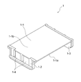
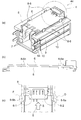
- FIG. 1 is a perspective view of the holder 1.
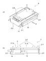
- FIG. 2A is a perspective view of the holder 2 provided in the battery pack 4, and
- FIG. 2B is a cross-sectional view of the holder 2 from the direction of the white arrow O in FIG. 3A is a perspective view of the battery pack 4, and
- FIG. 3B is a cross-sectional view of the battery pack 4 from the direction of the white arrow P in FIG. 3A.
- the battery pack 4 includes a battery cell 13 and a holder 2.
- the battery cell 13 is accommodated in the holder 2.
- the holder 2 has a flat plate member 2-1 having a first placement surface 2-1a on which the battery cell 13 is placed, and is substantially perpendicular to the first placement surface 2-1a.
- a first side surface member 2-2 and a second side surface member 2-3 extending to the placed side are provided.
- the battery cell 13 is fixed to the first placement surface 2-1a.
- the battery cell 13 is fixed to the first mounting surface 2-1a via an adhesive tape (not shown in FIG. 3).
- the adhesive tape is preferably a double-sided adhesive tape from the viewpoint of ease of handling and the like.
- the length Y1 of the first side surface member 2-2 and the second side surface member 2-3 extending to the side where the battery cell 13 is placed is equal to the length of the battery cell 13. It is larger than the length X1 in the direction substantially perpendicular to the mounting surface 2-1a. Since Y1 is longer than X1, when the battery cell 13 is fixed to the first mounting surface 2-1a, the battery cell 13 is suspended from the holder 2, and a space corresponding to the length of Y1-X1 is obtained. Can be secured. Due to this space, even if the battery cell 13 expands due to, for example, charging / discharging, there is no problem such as safety or poor appearance.
- the battery pack 4 it is possible to protect the battery cell 13 due to the presence of the above-described space, and excellent impact resistance can be obtained.
- the battery cell 13 and the substrate 6 can be insulated by the holder 2 and the energy density can be improved.
- the battery pack 4 may further include a substrate 6 (also referred to as a circuit substrate 6, hereinafter the same).
- the substrate 6 is accommodated in the holder 2.
- the flat plate member 2-1 included in the holder 2 has a second placement surface 2-1b for placing the substrate 6 on the back side of the first placement surface 2-1a.
- the substrate 6 is fixed to the second placement surface 2-1b by the hook portion 2-4. Details of the fixing method will be described later.
- the battery pack 4 may include a connection tab 14 that connects to the battery cell 13.
- the battery cell 13 is connected to the substrate 6 via the connection tab 14 and a connection member (not shown in FIG. 3).
- the battery pack 4 may include the holder 1 shown in FIG. 1 instead of including the holder 2. Further, when the substrate 6 is provided, the substrate 6 may be accommodated in a substrate holder 8 described later, and the holder 1 and the substrate holder 8 may be fixed. Examples of the fixing method include a method in which the holder 1 and the substrate holder 8 are fitted to each other by snap fitting or the like.
- the battery pack 4 may further include a connection tab 10 (14), a connection member 7, and / or an outer case (the outer half upper case 5 and the outer half lower case 15).
- the connection tab 10 (14), the connection member 7, and / or the exterior case (the exterior half upper case 5 and the exterior half lower case 15) will be described in detail in the second embodiment (example 2 of the battery pack). do.
- the holder 1 shown in FIG. 1 includes a flat plate member 1-1 having a first mounting surface 1-1a on which a battery cell (not shown) is mounted, and substantially perpendicular to the first mounting surface 1-1a.
- the first side member 1-2 and the second side member 1-3 extend to the side where the battery cell is placed.
- the battery cell is fixed to the first placement surface 1-1a.
- the battery cell is fixed to the first mounting surface 1-1a via an adhesive tape (not shown in FIG. 1).
- the adhesive tape is preferably a double-sided adhesive tape from the viewpoint of ease of handling and the like.
- the material of the holder 1 is not particularly limited, and examples thereof include an insulating material such as plastic.
- the material of the holder 1 may be a material having high thermal conductivity containing metal powder or carbon. By using such a material, the heat generated from the battery cell 13 (9) can be efficiently released to the outside.
- the material of the holder 1 may be a material containing glass fiber or carbon filler. In such a case, the mechanical strength of the holder 1 can be increased.
- the length of the first side surface member 1-2 and the second side surface member 1-3 extending to the side where the battery cell is placed is the first placement surface of the battery cell. It is larger than the length in a substantially vertical direction with respect to. When this length is large, a space is formed, and even if the battery cell expands due to, for example, charge / discharge, there is no problem such as safety or poor appearance.
- the substrate holder 8 may be fixed to the second placement surface 1-1b on the back side of the first placement surface 1-1a, and the substrate 6 may be accommodated in the substrate holder 8.
- the holder 1 When using the holder 1 to increase the number of battery cells, it is possible to design according to the number of battery cells by increasing the number of stages of the holder 1 to which the battery cells are fixed (adhered).
- a substrate holder 8 described later is fixed to the second mounting surface 1-1b of the uppermost holder 1 among the plurality of holders 1, and the substrate 6 is accommodated in the substrate holder 8. Also good.
- the two openings 1-4 shown in FIG. 1 are provided to further improve the heat dissipation. If the heat dissipation can be further improved by another means, the holder 1 has two The opening 1-4 may not be provided.
- the holder 2 shown in FIG. 2 is in a state in which the battery cell 9 (13) is not accommodated, and the constituent members of the holder 2 are as described above with reference to FIG. Then, explanation is omitted.
- the material of the holder 2 is the same as the material of the holder 1 described above.
- the uppermost portion is the holder 2 (the battery cell 13 and the substrate 6 are accommodated), and a plurality of steps of the holder 1 are placed under the holder 2.
- the holder 2 the battery cell 13 and the substrate 6 are accommodated
- a plurality of steps of the holder 1 are placed under the holder 2.
- the battery cell 13 (9) is not particularly limited and may be a known battery.
- a primary battery such as a manganese dry battery, an alkaline manganese dry battery, a lithium primary battery, a nickel-cadmium battery, a nickel-metal hydride battery, nickel -Secondary batteries such as zinc battery, lead battery, lithium secondary battery, lithium ion secondary battery, lithium ion polymer secondary battery, etc., and lithium ion secondary batteries are preferably used.
- the battery cell 13 (9) may be a laminate type battery or a cylindrical type battery, but a laminate type battery is preferably used.
- Second Embodiment (Example 2 of Battery Pack)> [3-1. Battery pack]
- the battery pack 40 (41 to 46) according to the second embodiment (Example 2 of the battery pack) according to the present technology will be described with reference to FIGS.
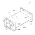
- FIG. 4 is a perspective view of the battery cell holder 3.
- FIG. 5 is a perspective view for explaining that the battery cell 9 is fixed to the battery cell holder 3.
- FIG. 6 is an exploded perspective view of the battery pack 40.
- 7A is a perspective view of the battery pack 40, and
- FIG. 7B is a cross-sectional view along the line AA shown in FIG. 7A.
- FIG. 8 is a schematic diagram of the battery pack 41
- FIG. 9 is a schematic diagram of the battery pack 42.
- FIG. 10 (a) is a perspective view of the battery pack 43
- FIG. 10 (b) is an enlarged view of the circular portion b shown in FIG. 10 (a)
- FIG. It is the enlarged view to which the circle part c shown by (a) was expanded.
- FIG. 11A is a perspective view of the battery pack 44.
- FIG. 11B is a cross-sectional view of a part of the battery pack 44 from the direction of the white arrow R in FIG. 11A, and is a diagram for explaining that the substrate 6 is fixed to the substrate holder 8.
- FIG. 11C is an enlarged view in which the circular portion c shown in FIG. 11A is enlarged, and is a view for explaining that the substrate 6 is fixed to the substrate holder 8.
- the battery pack 40 includes at least battery cells 9 and 13 and a battery cell holder 3.
- the battery cells 9 and 13 are accommodated in the battery cell holder 3.
- the battery cell holder 3 includes a flat plate member 3-1 having a first placement surface 3-1a on which the battery cell 13 is placed, and a first placement surface 3-1a.
- the first side surface member 3-4 and the second side surface member 3-5 are provided that are substantially perpendicular to each other and extend to the side on which the battery cell 13 is placed.
- the flat plate member 3-1 has a second mounting surface 3-1b on which the battery cell 9 is mounted on the back side of the first mounting surface 3-1a, and the battery cell holder 3 has the second mounting surface 3-1b.
- a third side surface member 3-2 and a fourth side surface member 3-3 that are substantially perpendicular to the surface 3-1b and extend to the side on which the battery cell 9 is placed are provided.
- the battery cell 13 is fixed to the first placement surface 3-1a, for example, via the double-sided adhesive tape 12, and the battery cell 13 is fixed to the first placement surface 3-1a.
- the battery cell 9 is fixed to the second placement surface 3-1b, for example, via a double-sided adhesive tape 11, and the battery cell 9 is fixed to the first placement surface 3-1b.
- a double-sided adhesive tape 11 is affixed to the second placement surface 3-1b of the battery cell holder 3 in advance.
- the battery cell 9 is stuck and fixed to the adhesive tape 11 of both surfaces toward the direction of the white arrow Q.
- the bottom surface of the battery cell 9 and the battery cell holder 3 are bonded via an adhesive tape.
- the bottom surface of the battery cell 9 to be bonded is the connection tab 10 of the two bottom surfaces of the battery cell 9 (an upper surface and a lower surface that are substantially perpendicular to the direction of the white arrow Q in FIG. 5).
- the battery cell 9 (13) can be accurately fixed to the battery cell holder 3. As long as the battery cell 9 (13) can be accurately fixed to the battery cell holder 3, a method other than the above-described method using the double-sided adhesive tape 11 (12) may be used.
- the length of the first side surface member 3-4 and the second side surface member 3-5 extending to the side on which the battery cell 13 is placed is the first placement surface 3-3 of the battery cell 13. It is larger than the length in the substantially vertical direction with respect to 1a.
- the length of the third side member 3-2 and the fourth side member 3-3 extending to the side on which the battery cell 9 is placed is substantially perpendicular to the second placement surface 3-1b of the battery cell 9. Greater than length. This will be described with reference to FIG. 7B, which is a cross-sectional view along the line AA shown in FIG.
- the length Y3 of the first side surface member 3-4 and the second side surface member 3-5 extending to the side where the battery cell 13 is mounted is substantially perpendicular to the first mounting surface 3-1a of the battery cell 13. Greater than the length X3. Since Y3 is longer than X3, when the battery cell 13 is fixed to the first placement surface 3-1a, the battery cell 13 is suspended from the battery cell holder 3, and is equivalent to the length of Y3-X3. Space C can be secured. By having this space C, even if the battery cell 13 expands due to, for example, charge / discharge, there is no problem such as safety or poor appearance.
- the length Y2 of the third side member 3-2 and the fourth side member 3-3 extending to the side on which the battery cell 9 is placed is equal to the second placement surface 3-1b of the battery cell 9. It is larger than the length X2 in the substantially vertical direction. Since Y2 is longer than X2, when the battery cell 9 is fixed to the first mounting surface 3-1b, the battery cell 9 is suspended from the battery cell holder 3, and is equivalent to the length of Y2-X2. Space B can be secured. Due to the presence of this space B, there is no problem even if the battery cell 9 expands due to, for example, charge / discharge.
- the presence of the spaces B and C makes it possible to protect the battery cells 9 and 13, and an excellent impact resistance is obtained.
- the energy density can be improved by setting the optimum value.
- the battery cell holder 3 can insulate the battery cell 9 from the battery cell 13, and the battery cell holder 3 and the substrate holder 8 can insulate the battery cell 13 from the substrate 6. Safety can be improved.
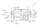
- FIG. 8 is a schematic view of the battery pack 41.
- the battery pack 41 has a one-stage battery cell holder 3 and a mounting surface 3-1a that the flat plate member 3-1 has on the one-stage battery cell holder 3.
- the two cells (battery cells) accommodated by being placed on each of the placement surfaces 3-1b, the first-stage substrate holder 8, and the first-stage substrate holder 8 have a flat plate member 8-1.
- a PWB (substrate) accommodated by being placed on the placement surface 8-1a.
- the length Y5 of the first side surface member 3-4 and the second side surface member 3-5 that extends to the side on which the Cell (battery cell) is placed is the first mount of the Cell (battery cell). It is larger than the length X5 in the direction substantially perpendicular to the placement surface 3-1a. Since Y5 is longer than X5, when the Cell is fixed to the first mounting surface 3-1a, the Cell is suspended from the battery cell holder 3, and a space corresponding to the length of Y5-X5 is secured. be able to. Due to the presence of this space, there is no problem even if the Cell (battery cell) expands due to, for example, charge / discharge.
- the length Y4 extending to the side on which the Cell (battery cell) is placed on the third side surface member 3-2 and the fourth side surface member 3-3 is the second placement surface of the Cell (battery cell). It is larger than the length X4 in the substantially vertical direction with respect to 3-1b. Since Y4 is longer than X4, when the Cell is fixed to the first mounting surface 3-1b, the Cell is suspended from the battery cell holder 3 to secure a space corresponding to the length of Y4-X4. be able to. Due to the presence of this space, even if the Cell (battery cell) expands due to, for example, charging / discharging or the like, there are no problems such as safety and poor appearance.
- the battery cell holder 3 and the substrate holder 8 include a concave portion 3-2-1 of the battery cell holder 3, a convex portion 8-2 (D1 portion in FIG. 8) of the substrate holder, and the battery cell holder 3.
- the concave member 3-3-1 and the convex portion 8-3 (D2 portion in FIG. 8) of the substrate holder are fitted by snap fitting, respectively, and the flat plate member 3-1 and the substrate holder provided in the battery cell holder 3 8 is fixed in a substantially vertical direction with respect to the flat plate member 8-1 included in the plate.
- the positional accuracy between the two cells (battery cells) and the PWB (substrate) can be improved.
- the arbitrary fixing methods may be sufficient.
- FIG. 9 is a schematic diagram of the battery pack 42.
- the battery pack 42 has two battery cell holders 3 and two placements of the two flat plate members 3-1 on the two battery cell holders 3.
- FIG. Four cells (battery cells) accommodated by being placed on the surface 3-1a and the two placement surfaces 3-1b, the first-stage substrate holder 8, and the first-stage substrate holder 8, respectively, At least a PWB (substrate) accommodated by being placed on the placement surface 8-1a of the member 8-1.
- the battery pack 42 includes two battery cell holders 3.
- the battery pack 42 may be composed of a one-stage substrate holder 8 and three or more battery cell holders 3. Further, the battery pack 42 is composed of an even number of battery cells.
- the cells (battery cells) of the first side surface member 3-4 and the second side surface member 3-5 are placed in the lower battery cell holder 3 in FIG.
- the length Y9 extending to the formed side is larger than the length X9 in the substantially vertical direction with respect to the first placement surface 3-1a of the Cell (battery cell). Since Y9 is longer than X9, when the Cell is fixed to the first mounting surface 3-1a, the Cell is suspended from the battery cell holder 3, and a space corresponding to the length of Y5-X5 is secured. be able to. Due to the presence of this space, even if the Cell (battery cell) expands due to, for example, charging / discharging or the like, there are no problems such as safety and poor appearance.
- the length Y8 extending to the side where the Cell (battery cell) is placed on the third side surface member 3-2 and the fourth side surface member 3-3 is the second placement surface of the Cell (battery cell). It is larger than the length X8 in the substantially vertical direction with respect to 3-1b. Since Y8 is longer than X8, when the Cell is fixed to the first mounting surface 3-1b, the Cell is suspended from the battery cell holder 3, and a space corresponding to the length of Y8-X8 is secured. be able to. Due to the presence of this space, even if the Cell (battery cell) expands due to, for example, charging / discharging or the like, there are no problems such as safety and poor appearance.
- the cells (battery cells) of the first side surface member 3-4 and the second side surface member 3-5 are mounted on the upper battery cell holder 3 in FIG.
- the length Y7 extending to the placed side is larger than the length X7 in the substantially vertical direction with respect to the first placement surface 3-1a of the Cell (battery cell). Since Y7 is longer than X7, when the Cell is fixed to the first mounting surface 3-1a, the Cell is suspended from the battery cell holder 3, and a space corresponding to the length of Y7-X7 is secured. be able to. Due to the presence of this space, even if the Cell (battery cell) expands due to, for example, charging / discharging or the like, there are no problems such as safety and poor appearance.
- the length Y6 extending to the side on which the Cell (battery cell) is placed on the third side surface member 3-2 and the fourth side surface member 3-3 is the second placement surface of the Cell (battery cell). It is larger than the length X6 in the substantially vertical direction with respect to 3-1b. Since Y6 is longer than X6, when the Cell is fixed to the first mounting surface 3-1b, the Cell is suspended from the battery cell holder 3, and a space corresponding to the length of Y6-X6 is secured. be able to. Due to the presence of this space, even if the Cell (battery cell) expands due to, for example, charging / discharging or the like, there are no problems such as safety and poor appearance.
- the two-stage battery cell holders 3 include a concave portion 3-2-2 included in the lower battery cell holder 3 in FIG. 9 and a convex portion 3-4-1 included in the upper battery cell holder 3 in FIG. 9), a concave portion 3-3-2 included in the lower battery cell holder 3 in FIG. 9, and a convex portion 3-5-1 included in the upper battery cell holder 3 in FIG.
- the E2 portion in the middle is fitted by a snap fit, and is fixed in a substantially vertical direction to the respective flat plate members 3-1 included in the two battery cell holders 3.
- the upper battery cell holder 3 and the substrate holder 8 in FIG. 9 are a concave portion 3-2-1 of the battery cell holder 3 and a convex portion 8-2 (D1 portion in FIG. 9) of the substrate holder.
- the concave portion 3-3-1 of the battery cell holder 3 and the convex portion 8-3 (D2 portion in FIG. 9) of the substrate holder are fitted with each other by snap fit, and the flat plate provided in the battery cell holder 3
- the plate member 8-1 and the flat plate member 8-1 included in the substrate holder 8 are fixed in a substantially vertical direction.
- the positional accuracy between the two cells (battery cells) and the PWB (substrate) can be improved.
- the arbitrary fixing methods may be sufficient.
- battery pack 43 the fixing between the battery cell holder 3 and the substrate holder 8 will be described in more detail.
- FIG. 10 (b) is an enlarged view in which the circular portion b shown in FIG. 10 (a) is enlarged.
- the protrusions 8-4 and 8-5 included in the substrate holder 8 and the recesses of the battery cell holder 3 are fitted by a snap fit so that the battery cell holder 3 and the substrate are fitted.
- the holder 8 is fixed. By this fixing, the positional accuracy between the battery cell holder 3 and the substrate holder 8 is improved.
- FIG. 10 (c) is an enlarged view in which the circular portion c shown in FIG. 10 (a) is enlarged.
- the convex portion 8-6 provided in the substrate holder 8 and the concave portion 3-7 provided in the battery cell holder 3 and the convex portion 8-7 provided in the substrate holder 8 and the concave portion provided in the battery cell holder 3.
- the battery cell holder 3 and the substrate holder 8 are fixed by fitting with each other 3-8 by snap fit. By this fixing, the positional accuracy between the battery cell holder 3 and the substrate holder 8 is improved.
- the battery cell holder 3 shown in FIG. 4 is in a state where the battery cells 9 and 13 are not accommodated, and the constituent members and the like of the battery cell holder 3 are as described above. Is omitted.
- the four openings 3-6 shown in FIG. 4 are provided to further improve the heat dissipation. If the heat dissipation can be further improved by another means, the battery cell holder 3 The four openings 3-6 may not be provided.
- the material of the battery cell holder 3 is not particularly limited, and examples thereof include an insulating material such as plastic.
- the material of the battery cell holder 3 may be a material having high thermal conductivity containing metal powder or carbon.
- the material of the battery cell holder 3 may be a material containing glass fiber or carbon filler. In such a case, the mechanical strength of the battery cell holder 3 can be increased.
- the battery pack 40 (44) includes at least the battery cells 9 and 13 and the battery cell holder 3, and further includes the substrate 6 and the substrate holder 8 that fixes and accommodates the substrate 6. Also good.
- a method of fixing the substrate 6 to the substrate holder 8 will be described with reference to FIG.
- the substrate 6 includes hook portions 8-6a and 8-6b (not shown in FIG. 11 (b)), 8-6c and 8-6d (FIG. 11) provided in the substrate holder 8. It is fixed to the substrate holder 8 through (not shown in (b)). By this fixing, the positional accuracy between the substrate 6 and the substrate holder 8 is improved.
- the material of the substrate holder 8 is not particularly limited, and examples thereof include an insulating material such as plastic. Further, the material of the substrate holder 8 may be a material having high thermal conductivity containing metal powder or carbon. By using such a material, heat generated from the substrate 6 can be efficiently released to the outside. Alternatively, the material of the substrate holder 8 may be a material containing glass fiber or carbon filler. In such a case, the mechanical strength of the substrate holder 8 can be increased.
- the notch 6-1 of the substrate 6 is inserted into the hook 8-6b, and the notch 6-2 of the substrate 6 is hooked.
- the substrate 6 is inserted into the portion 8-6a, and the substrate 6 is slid in the direction indicated by the white arrow S to fix the substrate 6 to the substrate holder 8.
- connection tab The battery pack 40 may further include a connection tab 10 (14).
- FIG. 12 shows the connection tab 10 (14).
- FIG. 12A is a perspective view of the connection tab 10 (14).
- FIG.12 (b) is a figure which shows the state which connected the connection tab and the battery cell 9 (13).
- FIG. 12C is a perspective view of the battery pack 45 and shows a state where the connection tab 10 and the connection member 7 are connected.
- connection tab 10 includes a first connection portion 10-5 (14-5) connected to one electrode (electrode A in FIG. 12) of the battery cell 9 (13) and the other of the battery cell 9 (13).
- the second connection portion 10-6 (14-6) connected to the electrode (electrode B in FIG. 12) is integrated with the insulating member 16.
- the insulating member 16 may be any material as long as it has insulating properties, but is preferably a resin material.
- connection tab 10 When the connection tab 10 is connected to the electrode tab, the assembly accuracy is improved while maintaining the positional accuracy of the solder location, and variations in the input to the substrate 6 (connection member 7) can be suppressed.
- tab of one electrode electrode A in FIG. 12
- the tab of the other electrode electrode B in FIG. 12
- Assembly accuracy is reduced and subsequent connections may be affected.
- the first connection portion 10-5 (14-5) includes a substantially rectangular portion 10-3 (14-3) and a tip portion 10-1 (14-1).
- the substantially rectangular portion 10-3 (14-3) is connected to the electrode A lead 17, and the tip portion 10-1 (14-1) is connected to the connecting member 7.
- the second connection portion 10-6 (14-6) includes a substantially rectangular portion 10-4 (14-4) and a tip portion 10-2 (14-2).
- the substantially rectangular portion 10-4 (14-4) is connected to the electrode B lead 18, and the distal end portion 10-2 (14-2) is connected to the connecting member 7.
- connection member 7 The battery pack 40 (46) may further include a connection member 7 that is connected to the connection tab 10 (14) and the substrate 6.
- connection member 7 the length of the connection member 7 in a direction substantially perpendicular to the connecting direction of the connection tab 10 (14), the connection member 7, and the substrate 6 gradually changes.
- FIG. 13 is a perspective view of the battery pack 46 including the connection member 7.
- FIG. 14A is a front view of the connection member 7.
- FIG. 14B is a view showing a state in which the connection member 7 is connected to the substrate 6.
- connection tab 10 (14) and the substrate 6 are gradually changed by gradually changing the length of the connection member 7 in a direction substantially perpendicular to the connecting direction of the connection tab 10 (14), the connection member 7, and the substrate 6. Since the stress does not concentrate on the bent portion of the connecting member 7 formed when connecting to the connecting member 7, the connecting member 7 does not break.
- the connection member 7 can be bent and used, so that the degree of freedom of arrangement of the battery cells 9 and 13 and the substrate 6 is improved.
- the substrate 6 can be provided so as to be stacked on the battery cells 9 and 13.
- the substrate is arranged in parallel with the cell in the direction in which the cell leads come out, or is arranged so that the tab is folded and the substrate is folded 90 °.
- the connection is made with a tab, a lead wire, etc., but the insulation between the battery cell and the substrate is necessary, and the lead and the cell It was difficult to connect, increasing the number of accessory parts and increasing the thickness. However, these are not problematic as described above by using the connecting member 7.
- connection member 7 since the conductor part inside the connection member 7 also has a degree of freedom such that the position of the input location can be left unchanged and the output location can be interchanged, the polarity of the battery cell is reversed as an effect (that is, The direction of the battery cell can be reversed).
- the connecting member 7 is composed of a connecting member 7-1, a connecting member 7-2, and a connecting member 7-3.
- An elliptical portion H1 in FIG. 14A corresponds to a constricted portion of the connection member 7-1
- an elliptical portion H2 in FIG. 14B is formed when the connection member 7-1 is connected to the substrate 6. This corresponds to the bent portion of the connecting member 7-1.
- 14A corresponds to the constricted portion of the connection member 7-3
- the oval portion I2 in FIG. 14B corresponds to the connection member 7-3 connected to the substrate 6. This corresponds to the bent portion of the connecting member 7-3 to be formed.
- the thickness of the constricted part of the connecting member 7-1 gradually changes and an angle R is provided.
- the bending portion of the connection member 7-1 is directed in a direction substantially perpendicular to the connection direction of the connection tab 10 (14), the connection member 7, and the substrate 6 in the direction indicated by the white arrow.
- the length of the connection member 7-1 in the direction gradually changes.
- the thickness of the constricted portion of the connecting member 7-3 gradually changes and an angle R is provided.
- the bent part of the connecting member 7-3 is substantially perpendicular to the connecting direction of the connecting tab 10 (14), the connecting member 7 and the substrate 6 in the T direction of the white arrow.
- the length of the connection member 7-3 is gradually changed.
- FIG. 15 is a diagram illustrating an example of a conventional connection member 70.
- FIG. 15A is a front view of the connection member 70.
- the connection member 70 is composed of a connection member 70-1, a connection member 70-2, and a connection member 70-3.
- FIGS. 15B to 15D are views showing a state in which the connection member 70 is connected to the substrate 6.
- the connecting member 70 for example, due to the shape of the outer case, a part of the connecting member 70 is narrowed as shown by the elliptical portion J1 to the elliptical portion J2 and the elliptical portion K1 in FIG. Since it has a neck-like shape and is bent at the neck portion, there is a concern about breakage due to stress concentration.
- the floating from the bent shape may occur. This floating occurs because the force cannot be transmitted to the bent part after being bent. That is, since the white arrows V1 and V2 are weaker than the white arrow W, the elliptical portions J3 and K2 and the circular portion J4 are lifted by the springback of the white arrows U1 to U3.
- the battery pack 40 may further include an exterior case.
- the exterior case includes an exterior half upper case 5 and an exterior half lower case 15.
- the exterior case is manufactured by attaching the exterior half upper case 5 and the exterior half lower case 15 with fastening screws (not shown).
- the material of the outer half upper case 5 and the outer half lower case 15 is not particularly limited, and examples thereof include an insulating material such as plastic.
- the outer case may be restricted in the stacking direction of the internal cells in order to achieve the appearance of the battery pack (expansion of shoulder R).
- the use of the connecting member 7 increases the degree of freedom of wiring, and it can be arranged so that the shoulder R of the battery cell corresponds to the appearance R of the battery pack. R) can be enlarged.
- FIG. 16 is a schematic diagram of the battery pack 50.
- the battery pack 50 is mounted on the mounting surface 2-1a of the flat plate member 2-1 on one holder 2 and one holder 2.
- PWB substrate
- battery cell holder 3 and two cells (battery cells) accommodated in one battery cell holder 3 by being placed on each of the placement surface 3-1a and the placement surface 3-1b of the flat plate member 3-1.
- the length Y12 of the first side surface member 3-4 and the second side surface member 3-5 that extends to the side on which the Cell (battery cell) is placed is the first mount of the Cell (battery cell). It is longer than the length X12 in the direction substantially perpendicular to the placement surface 3-1a. Since Y12 is longer than X12, when the Cell is fixed to the first mounting surface 3-1a, the Cell is suspended from the battery cell holder 3, and a space corresponding to the length of Y12-X12 is secured. be able to. Due to the presence of this space, even if the Cell (battery cell) expands due to, for example, charging / discharging or the like, there are no problems such as safety and poor appearance.
- the length Y10 extending to the side on which the Cell (battery cell) of the first side surface member 2-2 and the second side surface member 2-3 is placed is the length of the Cell (battery cell). It is larger than the length X10 in the direction substantially perpendicular to the mounting surface 2-1a. Since Y10 is longer than X10, when the Cell is fixed to the first mounting surface 2-1a, the Cell is suspended from the holder 2, and a space corresponding to the length of Y10-X10 can be secured. it can. Due to the presence of this space, even if the Cell (battery cell) expands due to, for example, charging / discharging or the like, there are no problems such as safety and poor appearance.
- the holder 2 and the battery cell holder 3 include a concave portion 3-2-1 of the battery cell holder 3, a convex portion 2-2-1 (K1 portion in FIG. 16) of the holder 2, and the battery cell holder 3.
- the concave portion 3-3-1 and the convex portion 2-3-1 (K2 portion in FIG. 16) of the holder 2 are respectively fitted by snap fitting so that the flat plate member 3-1 included in the battery cell holder 3 is fitted.
- the flat plate member 2-1 included in the holder 2 is fixed in a substantially vertical direction.
- FIG. 17 is a schematic view of the battery pack 51.
- the battery pack 51 is mounted on the mounting surface 2-1a of the flat plate member 2-1 in the first-stage holder 2 and the first-stage holder 2.
- the cell holder 3 and the two battery cell holders 3 are accommodated by being placed on the two placement surfaces 3-1a and the two placement surfaces 3-1b of the two flat plate members 3-1, respectively.
- the battery pack 51 includes two battery cell holders 3.
- the battery pack 51 may be composed of a one-stage holder 2 and three or more battery cell holders 3.
- the battery pack 51 is composed of an odd number of battery cells.
- the cells (battery cells) of the first side surface member 3-4 and the second side surface member 3-5 are mounted on the lower battery cell holder 3 in FIG.
- the length Y17 extending to the placed side is larger than the length X17 in the substantially vertical direction with respect to the first placement surface 3-1a of the Cell (battery cell). Since Y17 is longer than X17, when the Cell is fixed to the first mounting surface 3-1a, the Cell is suspended from the battery cell holder 3, and a space corresponding to the length of Y17-X17 is secured. be able to. Due to the presence of this space, even if the Cell (battery cell) expands due to, for example, charging / discharging or the like, there are no problems such as safety and poor appearance.
- the length Y16 extending to the side where the Cell (battery cell) is placed on the third side surface member 3-2 and the fourth side surface member 3-3 is the second placement surface of the Cell (battery cell). It is larger than the length X16 in the substantially vertical direction with respect to 3-1b. Since Y16 is longer than X16, when the Cell is fixed to the first mounting surface 3-1b, the Cell is suspended from the battery cell holder 3, and a space corresponding to the length of Y16-X16 is secured. be able to. Due to the presence of this space, even if the Cell (battery cell) expands due to, for example, charging / discharging or the like, there are no problems such as safety and poor appearance.
- the cells (battery cells) of the first side surface member 3-4 and the second side surface member 3-5 are mounted on the upper battery cell holder 3 in FIG.
- the length Y15 extending to the placed side is larger than the length X15 in the substantially vertical direction with respect to the first placement surface 3-1a of the Cell (battery cell). Since Y15 is longer than X15, when the Cell is fixed to the first mounting surface 3-1a, the Cell is suspended from the battery cell holder 3, and a space corresponding to the length of Y15-X15 is secured. be able to. Due to the presence of this space, even if the Cell (battery cell) expands due to, for example, charging / discharging or the like, there are no problems such as safety and poor appearance.
- the length Y14 extending to the side on which the Cell (battery cell) is placed on the third side surface member 3-2 and the fourth side surface member 3-3 is the second placement surface of the Cell (battery cell). It is larger than the length X14 in the substantially vertical direction with respect to 3-1b. Since Y14 is longer than X14, when the Cell is fixed to the first mounting surface 3-1b, the Cell is suspended from the battery cell holder 3, and a space corresponding to the length of Y14-X14 is secured. be able to. Due to the presence of this space, even if the Cell (battery cell) expands due to, for example, charging / discharging or the like, there are no problems such as safety and poor appearance.
- the two-stage battery cell holders 3 include a concave portion 3-2-2 provided in the lower battery cell holder 3 in FIG. 17 and a convex portion 3-4-1 provided in the upper battery cell holder 3 in FIG. 17), a concave portion 3-2-2 of the lower battery cell holder 3 in FIG. 17, and a convex portion 3-5-1 of the upper battery cell holder 3 in FIG. 17 (FIG. 17).
- a concave portion 3-2-2 provided in the lower battery cell holder 3 in FIG. 17 and a convex portion 3-4-1 provided in the upper battery cell holder 3 in FIG. 17
- a concave portion 3-2-2 of the lower battery cell holder 3 in FIG. 17 and a convex portion 3-5-1 of the upper battery cell holder 3 in FIG. 17 (FIG. 17).
- the upper battery cell holder 3 and holder 2 in FIG. 17 are a concave portion 3-2-1 of the battery cell holder 3 and a convex portion 2-2-1 of the holder 2 (K1 portion in FIG. 17).
- the concave portion 3-3-1 of the battery cell holder 3 and the convex portion 2-3-1 (K2 portion in FIG. 17) of the holder 2 are fitted by snap fitting, respectively, so that the battery cell holder 3 Are fixed in a substantially vertical direction with respect to the flat plate member 3-1 included in the flat plate member 2-1 and the flat plate member 2-1 included in the holder 2.
- the positional accuracy between the three cells (battery cells) and the PWB (substrate) can be improved.
- the arbitrary fixing methods may be sufficient.
- the battery pack can be used as long as it is a machine, device, instrument, device and system (an assembly of a plurality of devices) that can be used as a power source for driving or a power storage source for power storage.
- the battery pack used as a power source may be a main power source (a power source used preferentially) or an auxiliary power source (a power source used in place of or switched from the main power source).
- the type of main power source is not limited to the battery pack.
- the usage of the battery pack is, for example, as follows.
- It is a portable living device such as an electric shaver.
- Storage devices such as backup power supplies and memory cards.
- Electric tools such as electric drills and electric saws.
- Medical electronic devices such as pacemakers and hearing aids.
- It is a power storage system such as a home battery system that stores electric power in case of an emergency. Of course, other
- the battery pack is applied to a vehicle, a power storage system, a power tool, and an electronic device. This is because, since excellent battery characteristics are required, performance can be effectively improved by using the battery pack of the present technology.
- the vehicle is a vehicle that operates (runs) using the battery pack as a driving power source. As described above, the vehicle may be an automobile (hybrid automobile or the like) provided with a driving source other than the battery pack.
- the power storage system includes, for example, a residential power storage system, and uses a battery pack as a power storage source. In the power storage system, since power is stored in a battery pack that is a power storage source, a power consuming device, for example, a household electric product can be used by using the power.
- An electric power tool is a tool in which a movable part (for example, a drill etc.) moves, using a battery pack as a power source for driving.
- An electronic device is a device that exhibits various functions using a battery pack as a power source (power supply source) for driving.
- a vehicle according to a fourth embodiment of the present technology includes a battery pack according to the present technology, a driving force conversion device that converts electric power supplied from the battery pack according to the present technology into driving force, and driving according to the driving force. And a vehicle control device. Since the vehicle according to the fourth embodiment of the present technology includes the battery pack according to the present technology having excellent battery characteristics and excellent reliability, the performance and reliability of the vehicle are improved.
- FIG. 18 schematically shows an example of the configuration of a hybrid vehicle that employs a series hybrid system to which the present technology is applied.
- a series hybrid system is a car that runs on an electric power driving force conversion device using electric power generated by a generator driven by an engine or electric power once stored in a battery.
- the hybrid vehicle 7200 includes an engine 7201, a generator 7202, a power driving force conversion device 7203, a driving wheel 7204a, a driving wheel 7204b, a wheel 7205a, a wheel 7205b, a battery 7208, a vehicle control device 7209, various sensors 7210, and a charging port 7211. Is installed.
- a power storage device (not shown) is applied to the battery 7208.
- Hybrid vehicle 7200 travels using power driving force conversion device 7203 as a power source.
- An example of the power driving force conversion device 7203 is a motor.
- the electric power / driving force conversion device 7203 is operated by the electric power of the battery 7208, and the rotational force of the electric power / driving force conversion device 7203 is transmitted to the driving wheels 7204a and 7204b.
- the power driving force conversion device 7203 can be applied to either an AC motor or a DC motor by using DC-AC (DC-AC) or reverse conversion (AC-DC conversion) where necessary.
- Various sensors 7210 control the engine speed through the vehicle control device 7209 and control the opening of a throttle valve (throttle opening) (not shown).
- Various sensors 7210 include a speed sensor, an acceleration sensor, an engine speed sensor, and the like.
- the rotational force of the engine 7201 is transmitted to the generator 7202, and the electric power generated by the generator 7202 by the rotational force can be stored in the battery 7208.
- the resistance force at the time of deceleration is applied as a rotational force to the power driving force conversion device 7203, and the regenerative power generated by the power driving force conversion device 7203 by this rotational force is applied to the battery 7208. Accumulated.
- the battery 7208 is connected to an external power source of the hybrid vehicle, so that the battery 7208 can receive power from the external power source using the charging port 211 as an input port and store the received power.
- an information processing device that performs information processing related to vehicle control based on information related to the secondary battery may be provided.
- an information processing apparatus for example, there is an information processing apparatus that displays a remaining battery level based on information on the remaining battery level.
- the series hybrid vehicle that runs on the motor using the power generated by the generator driven by the engine or the power stored once in the battery has been described as an example.
- the present disclosure is also effective for a parallel hybrid vehicle that uses both engine and motor outputs as drive sources, and switches between the three modes of running with the engine alone, running with the motor alone, and engine and motor running as appropriate. Applicable.
- the present technology can be effectively applied to a so-called electric vehicle that travels only by a drive motor without using an engine.
- a power storage system includes a power storage device including the battery pack according to the present technology, a power consuming device to which power is supplied from the battery pack according to the present technology, and the power consumption from the battery pack.
- An electrical storage system comprising: a control device that controls power supply to the device; and a power generation device that charges a battery pack. Since the power storage system of the fifth embodiment according to the present technology includes the battery pack according to the present technology having excellent battery characteristics and excellent reliability, the performance and reliability of the power storage system are improved.
- a power storage system 9100 for a house 9001 electric power is supplied from a centralized power system 9002 such as a thermal power generation 9002a, a nuclear power generation 9002b, and a hydropower generation 9002c via a power network 9009, an information network 9012, a smart meter 9007, a power hub 9008, and the like.
- the power is supplied to the power storage device 9003.
- power is supplied to the power storage device 9003 from an independent power source such as the home power generation device 9004.
- the electric power supplied to the power storage device 9003 is stored. Electric power used in the house 9001 is supplied using the power storage device 9003.
- the same power storage system can be used not only for the house 9001 but also for buildings.
- the house 9001 is provided with a power generation device 9004, a power consumption device 9005, a power storage device 9003, a control device 9010 that controls each device, a smart meter 9007, and a sensor 9011 that acquires various types of information.
- Each device is connected by a power network 9009 and an information network 9012.
- a solar cell, a fuel cell, or the like is used, and the generated power is supplied to the power consumption device 9005 and / or the power storage device 9003.
- the power consuming apparatus 9005 is a refrigerator 9005a, an air conditioner 9005b, a television receiver 9005c, a bath 9005d, or the like.
- the electric power consumption device 9005 includes an electric vehicle 9006.
- the electric vehicle 9006 is an electric vehicle 9006a, a hybrid car 9006b, and an electric motorcycle 9006c.
- the battery unit of the present disclosure described above is applied to the power storage device 9003.
- the power storage device 9003 is composed of a secondary battery or a capacitor.
- a lithium ion battery is used.
- the lithium ion battery may be a stationary type or used in the electric vehicle 9006.
- the smart meter 9007 has a function of measuring the usage amount of commercial power and transmitting the measured usage amount to an electric power company.
- the power network 9009 may be any one or a combination of DC power supply, AC power supply, and non-contact power supply.
- Various sensors 9011 are, for example, human sensors, illuminance sensors, object detection sensors, power consumption sensors, vibration sensors, contact sensors, temperature sensors, infrared sensors, and the like. Information acquired by the various sensors 9011 is transmitted to the control device 9010. Based on the information from the sensor 9011, the weather condition, the condition of the person, and the like can be grasped, and the power consumption device 9005 can be automatically controlled to minimize the energy consumption. Furthermore, the control device 9010 can transmit information regarding the house 9001 to an external power company or the like via the Internet.
- the power hub 9008 performs processing such as branching of power lines and DC / AC conversion.
- the communication method of the information network 9012 connected to the control device 9010 includes a method using a communication interface such as UART (Universal Asynchronous Receiver-Transmitter), Bluetooth (registered trademark), ZigBee, Wi-Fi, etc. There is a method of using a sensor network according to the wireless communication standard of.
- the Bluetooth (registered trademark) system is applied to multimedia communication and can perform one-to-many connection communication.
- ZigBee uses the physical layer of IEEE (Institut of Electric-and-Electronics-Engineers) 802.15.4.
- IEEE 802.15.4 is the name of a short-range wireless network standard called PAN (Personal AreaNetwork) or W (Wireless) PAN.
- the control device 9010 is connected to an external server 9013.
- the server 9013 may be managed by any one of the house 9001, the electric power company, and the service provider.
- Information transmitted / received by the server 9013 is, for example, information on power consumption information, life pattern information, power charges, weather information, natural disaster information, and power transactions. These pieces of information may be transmitted / received from a power consuming device (for example, a television receiver) in the home, or may be transmitted / received from a device outside the home (for example, a mobile phone). Such information may be displayed on a device having a display function, such as a television receiver, a mobile phone, a personal digital assistant (PDA), or the like.
- PDA personal digital assistant
- the control device 9010 that controls each unit includes a CPU, a RAM (Random Access Memory), a ROM (Read Only Memory), and the like, and is stored in the power storage device 9003 in this example.
- the control device 9010 is connected to the power storage device 9003, the home power generation device 9004, the power consumption device 9005, the various sensors 9011, the server 9013, and the information network 9012.
- the control device 9010 functions to adjust the amount of commercial power used and the amount of power generation. have. In addition, you may provide the function etc. which carry out an electric power transaction in an electric power market.
- electric power can be stored not only in the centralized power system 9002 such as the thermal power 9002a, the nuclear power 9002b, and the hydropower 9002c but also in the power storage device 9003 in the power generation device 9004 (solar power generation, wind power generation). it can. Therefore, even if the generated power of the home power generation apparatus 9004 fluctuates, it is possible to perform control such that the amount of power to be sent to the outside is constant or discharge is performed as necessary.
- the power obtained by solar power generation is stored in the power storage device 9003, and midnight power with a low charge is stored in the power storage device 9003 at night, and the power stored by the power storage device 9003 is discharged during a high daytime charge. You can also use it.
- control device 9010 is stored in the power storage device 9003 .
- control device 9010 may be stored in the smart meter 9007 or may be configured independently.
- the power storage system 9100 may be used for a plurality of homes in an apartment house, or may be used for a plurality of detached houses.
- the electric tool according to the sixth embodiment of the present technology is an electric tool including the battery pack according to the present technology and a movable part to which electric power is supplied from the battery pack. Since the electric tool of the sixth embodiment according to the present technology includes the battery pack according to the present technology having excellent battery characteristics and excellent reliability, the performance of the electric tool is improved.
- FIG. 20 shows a block configuration of the electric tool.
- This electric tool is, for example, an electric drill, and includes a control unit 99 and a power supply 100 inside a tool main body 98 formed of a plastic material or the like.
- a drill portion 101 which is a movable portion is attached to the tool body 98 so as to be operable (rotatable).
- the control unit 99 controls the operation of the entire power tool (including the usage state of the power supply 100), and includes, for example, a CPU.
- the power supply 100 includes the battery pack (not shown) according to the present technology described above.
- the control unit 99 supplies power from the power supply 100 to the drill unit 101 in response to an operation switch (not shown).
- the electronic device according to the seventh embodiment of the present technology is an electronic device that includes the battery pack according to the present technology and receives power supply from the battery pack. As described above, the electronic device according to the seventh embodiment of the present technology is a device that exhibits various functions using the battery pack as a driving power source (power supply source). Since the electronic device according to the seventh embodiment of the present technology includes the battery pack according to the present technology having excellent battery characteristics and excellent reliability, the performance and reliability of the electronic device are improved.
- the electronic device 400 includes an electronic circuit 401 of the electronic device body and a battery pack 300.
- the battery pack 300 according to the present technology can be applied to the battery pack 300.
- the battery pack 300 is electrically connected to the electronic circuit 401 via the positive terminal 331a and the negative terminal 331b.
- the electronic device 400 has a configuration in which the battery pack 300 is detachable by a user.
- the configuration of the electronic device 400 is not limited to this, and the battery pack 300 is built in the electronic device 400 so that the user cannot remove the battery pack 300 from the electronic device 400. May be.
- the positive terminal 331a and the negative terminal 331b of the battery pack 300 are connected to the positive terminal and the negative terminal of a charger (not shown), respectively.
- the positive terminal 331a and the negative terminal 331b of the battery pack 300 are connected to the positive terminal and the negative terminal of the electronic circuit 401, respectively.
- Examples of the electronic device 400 include a notebook personal computer, a tablet computer, a mobile phone (for example, a smartphone), a personal digital assistant (PDA), an imaging device (for example, a digital still camera, a digital video camera), and an audio device (for example, Portable audio players), game devices, cordless phones, electronic books, electronic dictionaries, radio, headphones, navigation systems, memory cards, pacemakers, hearing aids, lighting equipment, toys, medical equipment, robots, etc. It is not limited. As a specific example, a head-mounted display and a band-type electronic device will be described.
- the head-mounted display includes an image display device, a mounting device for mounting the image display device on an observer's head, and the image display device.
- the band-type electronic device includes a plurality of segments connected in a band shape and a plurality of segments.
- the battery pack according to the present technology is an electronic device disposed in the segment.
- the electronic circuit 401 includes, for example, a CPU, a peripheral logic unit, an interface unit, a storage unit, and the like, and controls the entire electronic device 400.
- the battery pack 300 includes an assembled battery 301 and a charge / discharge circuit 302.
- the assembled battery 301 is configured by connecting a plurality of secondary batteries 301a in series and / or in parallel.
- the plurality of secondary batteries 301a are connected, for example, in n parallel m series (n and m are positive integers).
- FIG. 6 shows an example in which six secondary batteries 301a are connected in two parallel three series (2P3S).
- the charging / discharging circuit 302 controls charging of the assembled battery 301.
- the charging / discharging circuit 302 controls the discharging of the electronic device 400.
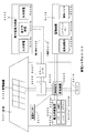
- the battery pack described above can be mounted on a printed circuit board 1202 (print circuit board, hereinafter referred to as “PCB”) together with a charging circuit or the like.
- a battery pack 1203 and an electronic circuit such as a charging circuit can be mounted on the PCB 1202 by a reflow process.
- a battery module 1201 in which an electronic circuit such as a battery pack 1203 and a charging circuit is mounted on the PCB 1202 is referred to as a battery module 1201.
- the battery module 1201 has a card type configuration as necessary, and can be configured as a portable card type mobile battery.
- a charge control IC IntegratedIntegrCircuit
- a battery protection IC 1205, and a battery remaining amount monitoring IC 1206 are also formed.
- the battery protection IC 1205 controls the charging / discharging operation so that the charging voltage does not become excessive at the time of charging / discharging, an overcurrent flows due to a load short circuit, and no overdischarging occurs.
- a USB (Universal Serial Bus) interface 1207 is attached to the PCB 1202.
- the battery pack 1203 is charged by the power supplied through the USB interface 1207.
- the charging operation is controlled by the charging control IC 1204.
- predetermined power for example, a voltage of 4.2 V
- the remaining battery level of the battery pack 1203 is monitored by the remaining battery level monitoring IC 1206 so that a display (not shown) indicating the remaining battery level can be seen from the outside.
- the USB interface 1207 may be used for load connection.
- a specific example of the load 1209 described above is as follows.
- A. Wearable devices sports watches, watches, hearing aids, etc.
- B. IoT terminals sensor network terminals, etc.
- C. Amusement equipment portable game terminals, game controllers
- D. IC board embedded battery real-time clock IC
- E. Energy harvesting equipment storage elements for power generation elements such as solar power generation, thermoelectric power generation, vibration power generation).
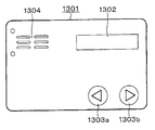
- FIG. 23 shows an example of the configuration of the universal credit card 1301. It has a card shape, and contains an IC chip and a battery pack (not shown) according to the present technology. Further, a display 1302 that consumes less power and an operation unit such as direction keys 1303a and 1303b are provided. Further, a charging terminal 1304 is provided on the surface of the universal credit card 1301.
- the user can specify a credit card or the like loaded in advance on the universal credit card 1301 by operating the direction keys 1303a and 1303b while looking at the display 1302.
- a credit card or the like loaded in advance on the universal credit card 1301 by operating the direction keys 1303a and 1303b while looking at the display 1302.
- information indicating each credit card is displayed on the display 1302, and the user can designate a desired credit card by operating the direction keys 1303a and 1303b. After that, it can be used like a conventional credit card.
- the battery pack according to the present technology can be applied to any electronic card other than the universal credit card 1301.
- a wearable terminal is a wristband type electronic device.
- the wristband type activity meter is also called a smart band, and it is possible to obtain data on human activities such as the number of steps, distance traveled, calories burned, sleep amount, heart rate, etc. just by wrapping around the wrist. It can be done.
- the acquired data can also be managed with a smartphone.
- a mail transmission / reception function can be provided. For example, a mail notification function that notifies a user of an incoming mail by an LED (Light Emitting Diode) lamp and / or vibration is used.
- LED Light Emitting Diode
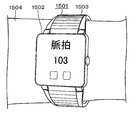
- FIG. 24 and 25 show an example of a wristband type activity meter that measures, for example, a pulse.
- FIG. 9 shows an example of the external configuration of the wristband type activity meter 1501.
- FIG. 25 shows a configuration example of the main body 1502 of the wristband type activity meter 1501.
- the wristband type activity meter 1501 is a wristband type measuring device that measures, for example, a pulse of a subject by an optical method.
- the wristband type active mass meter 1501 includes a main body 1502 and a band 1503, and the band 1503 is attached to the arm (wrist) 1504 of the subject like a wristwatch.
- the main-body part 1502 irradiates the measurement light of a predetermined wavelength to the part containing the pulse of a test subject's arm 1504, and measures a test subject's pulse based on the intensity
- the main body 1502 is configured to include a substrate 1521, an LED 1522, a light receiving IC 1523, a light shield 1524, an operation unit 1525, an arithmetic processing unit 1526, a display unit 1527, and a wireless device 1528.
- the LED 1522, the light receiving IC 1523, and the light shield 1524 are provided over the substrate 1521.
- the LED 1522 irradiates a portion including the pulse of the arm 1504 of the subject under measurement light of a predetermined wavelength under the control of the light receiving IC 1523.
- the light receiving IC 1523 receives light that has returned after the measurement light is applied to the arm 1504.
- the light receiving IC 1523 generates a digital measurement signal indicating the intensity of the returned light, and supplies the generated measurement signal to the arithmetic processing unit 1526.
- the light shield 1524 is provided between the LED 1522 and the light receiving IC 1523 on the substrate 1521.
- the light shield 1524 prevents measurement light from the LED 1522 from directly entering the light receiving IC 1523.
- the operation unit 1525 is composed of various operation members such as buttons and switches, and is provided on the surface of the main body 1502 or the like.
- the operation unit 1525 is used to operate the wristband type activity meter 1501 and supplies a signal indicating the operation content to the arithmetic processing unit 1526.
- the arithmetic processing unit 1526 performs arithmetic processing for measuring the pulse of the subject based on the measurement signal supplied from the light receiving IC 1523.
- the arithmetic processing unit 1526 supplies the pulse measurement result to the display unit 1527 and the wireless device 1528.
- the display unit 1527 is configured by a display device such as an LCD (Liquid Crystal Display), and is provided on the surface of the main body unit 1502.
- the display unit 1527 displays the measurement result of the subject's pulse and the like.
- the wireless device 1528 transmits the measurement result of the subject's pulse to an external device by wireless communication of a predetermined method. For example, as illustrated in FIG. 25, the wireless device 1528 transmits the measurement result of the subject's pulse to the smartphone 1505 and causes the screen 1506 of the smartphone 1505 to display the measurement result. Furthermore, the measurement result data is managed by the smartphone 1505, and the measurement result can be browsed by the smartphone 1505 or stored in a server on the network. Note that any method can be adopted as a communication method of the wireless device 1528.
- the light receiving IC 1523 can also be used when measuring a pulse in a part other than the subject's arm 1504 (eg, finger, earlobe, etc.).
- the wristband type active mass meter 1501 described above can accurately measure the pulse wave and pulse of the subject by removing the influence of body movement by the signal processing in the light receiving IC 1523. For example, even if the subject performs intense exercise such as running, the pulse wave and pulse of the subject can be accurately measured. In addition, for example, even when the subject wears the wristband type activity meter 1501 for a long time and performs measurement, the influence of the subject's body movement can be removed and the pulse wave and the pulse can be accurately measured. .
- the power consumption of the wristband type activity meter 1501 can be reduced by reducing the amount of calculation. As a result, for example, it is possible to perform measurement by wearing the wristband type activity meter 1501 on the subject for a long time without performing charging or battery replacement.
- the wristband type activity meter 1501 includes an electronic circuit of the main body and a battery pack.
- the battery pack is detachable by the user.
- the electronic circuit is a circuit included in the main body 1502 described above. The present technology can be applied when using a battery pack.
- FIG. 26 shows a structural example of the appearance of a wristband type electronic device 1601 (hereinafter simply referred to as “electronic device 1601”).
- the electronic device 1601 is, for example, a watch-type so-called wearable device that is detachable from the human body.
- the electronic device 1601 includes, for example, a band portion 1611 attached to the arm, a display device 1612 that displays numbers, characters, symbols, and the like, and operation buttons 1613.
- the band portion 1611 is formed with a plurality of hole portions 1611a and protrusions 1611b formed on the inner peripheral surface (the surface that comes into contact with the arm when the electronic device 1601 is attached).
- the electronic device 1601 In the use state, the electronic device 1601 is bent so that the band portion 1611 is substantially circular as shown in FIG. 26, and the protrusion 1611b is inserted into the hole portion 1611a and attached to the arm. By adjusting the position of the hole 1611a into which the protrusion 1611b is inserted, the diameter can be adjusted corresponding to the thickness of the arm.
- the protrusion 1611b is removed from the hole 1611a, and the band 1611 is stored in a substantially flat state.
- the sensor according to the embodiment of the present technology is provided over the entire band portion 1611.
- Smart watches have the same or similar appearance as existing wristwatch designs, and are worn on the user's wrist in the same way as wristwatches. Information displayed on the display is used to receive incoming calls and e-mails. A function for notifying the user of various messages such as. Further, smart watches having functions such as an electronic money function and an activity meter have been proposed. In the smart watch, a display is incorporated on the surface of the main body portion of the electronic device, and various information is displayed on the display. In addition, the smart watch can also cooperate with functions, contents, and the like of the communication terminal by performing short-range wireless communication such as Bluetooth (registered trademark) with a communication terminal (smart phone or the like).
- short-range wireless communication such as Bluetooth (registered trademark)
- a communication terminal smart watch
- a plurality of segments connected in a band, a plurality of electronic components arranged in the plurality of segments, and a plurality of electronic components in the plurality of segments are connected to each other in at least one segment.
- a device including a flexible circuit board arranged in a meandering shape has been proposed. By having such a meandering shape, the flexible circuit board is not stressed even when the band is bent, and the circuit is prevented from being cut.
- the smart watch of this application example can perform notifications such as e-mails and incoming calls, log recording of user action history, telephone calls, and the like.
- the smart watch has a function as a non-contact IC card, and can perform settlement, authentication, and the like in a non-contact manner.
- the smart watch of this application example has built-in circuit components that perform communication processing and notification processing in a metal band.
- the band is configured by connecting a plurality of segments, and a circuit board, a vibration motor, a battery, and an acceleration sensor are accommodated in each segment.
- Components such as circuit boards, vibration motors, batteries, and acceleration sensors in each segment are connected by a flexible printed circuit board (FPC).
- FPC flexible printed circuit board
- Fig. 27 shows the overall structure (disassembled perspective view) of the smart watch.
- the band-type electronic device 2000 is a metal band attached to the watch main body 3000 and is attached to the user's arm.
- the watch body 3000 includes a dial 3100 for displaying time.
- the watch body 3000 may display the time electronically on a liquid crystal display or the like instead of the dial 3100.
- the band-type electronic device 2000 has a configuration in which a plurality of segments 2110 to 2230 are connected.
- the segment 2110 is attached to one band attachment hole of the watch body 3000, and the segment 2230 is attached to the other band attachment hole of the watch body 3000.
- each of the segments 2110 to 2230 is made of metal.
- FIG. 28 shows a part of the internal configuration of the band-type electronic apparatus 2000.
- the inside of three segments 2170, 2180, 2190, 2200, and 2210 is shown.
- a flexible circuit board 2400 is arranged inside five continuous segments 2170 to 2210.
- Various electronic components are disposed in the segment 2170, and batteries 2411 and 2421 according to the present technology are disposed in the segments 2190 and 2210, and these components are electrically connected by the flexible circuit board 2400.
- a segment 2180 between the segment 2170 and the segment 2190 has a relatively small size, and the flexible circuit board 2400 in a meandering state is disposed.
- the flexible circuit board 2400 is disposed in a state of being sandwiched between waterproofing members.
- the inside of the segments 2170 to 2210 has a waterproof structure.
- FIG. 29 is a block diagram showing a circuit configuration of the band-type electronic apparatus 2000.
- the circuit inside the band-type electronic device 2000 has a configuration independent of the watch main body 3000.
- the watch main body 3000 includes a movement unit 3200 that rotates hands arranged on the dial 3100.
- a battery 3300 is connected to the movement unit 3200.
- the movement unit 3200 and the battery 3300 are built in the casing of the watch main body 3000.
- a data processing unit 4101 In the segment 2170, a data processing unit 4101, a wireless communication unit 4102, an NFC communication unit 4104, and a GPS unit 4106 are arranged.
- Antennas 4103, 4105, and 4107 are connected to the wireless communication unit 4102, the NFC communication unit 4104, and the GPS unit 4106, respectively.
- the respective antennas 4103, 4105, and 4107 are disposed in the vicinity of a slit 2173 described later of the segment 2170.
- the wireless communication unit 4102 performs short-range wireless communication with other terminals based on, for example, Bluetooth (registered trademark) standards.
- the NFC communication unit 4104 performs wireless communication with an adjacent reader / writer according to the NFC standard.
- the GPS unit 4106 is a positioning unit that receives radio waves from a satellite of a system called GPS (Global Positioning System) and measures the current position. Data obtained by the wireless communication unit 4102, the NFC communication unit 4104, and the GPS unit 4106 is supplied to the data processing unit 4101.
- GPS Global Positioning System
- a display 4108 In the segment 2170, a display 4108, a vibrator 4109, a motion sensor 4110, and an audio processing unit 4111 are arranged.
- the display 4108 and the vibrator 4109 function as a notification unit that notifies the wearer of the band-type electronic device 2000.
- the display 4108 includes a plurality of light emitting diodes, and notifies the user by lighting or blinking of the light emitting diodes.
- the plurality of light emitting diodes are disposed, for example, in a slit 2173 described later of the segment 2170, and notification of incoming calls or reception of e-mails is made by lighting or blinking.
- the display 4108 may be a type that displays characters, numbers, and the like.
- Vibrator 4109 is a member that vibrates segment 2170.
- the band-type electronic device 2000 notifies the incoming call or the reception of an e-mail by the vibration of the segment 2170 by the vibrator 4109.
- the motion sensor 4110 detects the movement of the user wearing the band-type electronic device 2000.
- an acceleration sensor As the motion sensor 4110, an acceleration sensor, a gyro sensor, an electronic compass, an atmospheric pressure sensor, or the like is used.
- the segment 2170 may incorporate a sensor other than the motion sensor 4110.
- a biosensor that detects the pulse of the user wearing the band-type electronic device 2000 may be incorporated.
- a microphone 4112 and a speaker 4113 are connected to the audio processing unit 4111, and the audio processing unit 4111 performs a call process with the other party connected by wireless communication in the wireless communication unit 4102.
- the voice processing unit 4111 can also perform processing for voice input operation.
- the segment 2190 has a built-in battery 2411
- the segment 2210 has a built-in battery 2421.
- the batteries 2411 and 2421 can be configured by a battery pack according to the present technology, and supply driving power to the circuits in the segment 2170.
- the circuit in the segment 2170 and the batteries 2411 and 2421 are connected by a flexible circuit board 2400 (FIG. 28).
- the segment 2170 includes terminals for charging the batteries 2411 and 2421.
- electronic components other than the batteries 2411 and 2421 may be arranged in the segments 2190 and 2210.
- the segments 2190 and 2210 may include a circuit that controls charging and discharging of the batteries 2411 and 2421.
- the glasses-type terminal described below can display information such as text, symbols, and images superimposed on the scenery in front of you. That is, a light-weight and thin image display device display module dedicated to a transmissive glasses-type terminal is mounted.
- a typical example is a head-mounted display (head mounted display (HMD)).
- This image display device comprises an optical engine and a hologram light guide plate.
- the optical engine emits image light such as an image and text using a micro display lens. This image light is incident on the hologram light guide plate.
- a hologram light guide plate has hologram optical elements incorporated at both ends of a transparent plate, and propagates image light from an optical engine through a very thin transparent plate having a thickness of 1 mm to the eyes of an observer. deliver. With such a configuration, a lens having a transmittance of, for example, 85% and a thickness of 3 mm (including protective plates before and after the light guide plate) is realized. With such a glasses-type terminal, it is possible to see the results of players and teams in real time while watching sports, and to display a tourist guide at a destination.
- the image display unit has a glasses-type configuration as shown in FIG. That is, as with normal glasses, the frame 5003 for holding the right image display unit 5001 and the left image display unit 5002 is provided in front of the eyes.
- the frame 5003 includes a front portion 5004 disposed in front of the observer, and two temple portions 5005 and 5006 that are rotatably attached to both ends of the front portion 5004 via hinges.
- the frame 5003 is made of the same material as that of normal glasses, such as metal, alloy, plastic, or a combination thereof.
- a headphone unit may be provided.
- the right image display unit 5001 and the left image display unit 5002 are arranged so as to be positioned in front of the user's right eye and in front of the left eye, respectively.
- Temple units 5005 and 5006 hold the image display units 5001 and 5002 on the user's head.
- a right display driving unit 5007 is disposed inside the temple unit 5005 at a connection portion between the front unit 5004 and the temple unit 5005.
- a left display driving unit 5008 is arranged inside the temple unit 5006 at a connection portion between the front unit 5004 and the temple unit 5006.
- a battery pack, an acceleration sensor, a gyroscope, an electronic compass, a microphone / speaker, and the like are mounted on the frame 5003. Further, an image pickup apparatus is attached, and still images / moving images can be taken.
- a controller connected to the glasses unit via, for example, a wireless or wired interface is provided.
- the controller is provided with a touch sensor, various buttons, a speaker, a microphone, and the like.
- it has a linkage function with a smartphone. For example, it is possible to provide information according to the user's situation by utilizing the GPS function of a smartphone.
- the present technology is not limited to the above-described embodiments and application examples, and can be changed without departing from the gist of the present technology.
- this technique can also take the following structures.
- the battery cell is housed in the holder;
- the holder has a flat plate-like member having a first placement surface on which the battery cell is placed, and is substantially perpendicular to the first placement surface and extends to the side on which the battery cell is placed.
- a first side member and a second side member The length of the first side member and the second side member extending to the side on which the battery cell is placed is larger than the length of the battery cell in the direction substantially perpendicular to the first placement surface. pack.
- connection tab has a configuration in which a first connection portion connected to one electrode of the battery cell and a second connection portion connected to the other electrode of the battery cell are integrated with an insulating member.
- a battery cell and a battery cell holder are provided at least, The battery cell is housed in the battery cell holder;
- the battery cell holder is a flat member having a first placement surface on which the battery cell is placed, and is substantially perpendicular to the first placement surface, on the side on which the battery cell is placed.
- a first side member and a second side member extending, The length of the first side member and the second side member extending to the side on which the battery cell is placed is greater than the length of the battery cell in a direction substantially perpendicular to the first placement surface
- the flat plate member has a second mounting surface on which the battery cell is mounted on the back side of the first mounting surface;
- the battery cell holder includes a third side surface member and a fourth side surface member that are substantially perpendicular to the second mounting surface and extend to a side on which the battery cell is mounted; The length of the third side member and the fourth side member extending to the side on which the battery cell is placed is larger than the length of the battery cell in the direction substantially perpendicular to the second placement surface. pack.
- a substrate and a substrate holder are provided, The substrate is received in the substrate holder;
- the connection tab has a configuration in which a first connection portion connected to one electrode of the battery cell and a second connection portion connected to the other electrode of the battery cell are integrated with an insulating member.
- connection member connected to the connection tab and the substrate;
- the battery pack according to any one of [1] to [13]; A driving force conversion device that receives supply of electric power from the battery pack and converts it into driving force of a vehicle; A drive unit that is driven according to the drive force; A vehicle comprising: a vehicle control device.
- a power storage device having the battery pack according to any one of [1] to [13]; A power consuming device to which power is supplied from the battery pack; A control device for controlling power supply from the battery pack to the power consuming device;
- a power storage system comprising: a power generation device that charges the battery pack.
- the battery pack according to any one of [1] to [13] is provided, An electronic device that receives power supply from the battery pack.
Landscapes
- Chemical & Material Sciences (AREA)
- Chemical Kinetics & Catalysis (AREA)
- Electrochemistry (AREA)
- General Chemical & Material Sciences (AREA)
- Battery Mounting, Suspending (AREA)
Abstract
優れた電池特性及び優れた信頼性を有する電池パックを提供すること。 電池セルと、ホルダーとを、少なくとも備え、電池セルがホルダーに収容さ れ、ホルダーが、電池セルを載置した第1載置面を有する平板状部材と、第1載置面に対して略垂直であって、電池セルが載置された側に延在する第1側面部材及び第2側面部材とを備え、第1側面部材及び第2側面部材の電池セルが載置された側に延在する長さが、電池セルの第1載置面に対する略垂直方向の長さよりも大きい、電池パックを提供する。
Description
本技術は、電池パックに関し、より詳しくは、電池パック、車両、蓄電システム、電動工具及び電子機器に関する。
近年、パーソナルコンピュータ、携帯通信端末などの電子機器、電気自動車などの自動車、風力発電などの新エネルギーシステム等の技術分野では、電池パックの需要が急速に拡大している。
例えば、第一の板状部と、前記第一の板状部の幅方向の両端部に一体に結合し、前記第一の板状部の両面に対して略垂直方向に延びる第二の板状部とを有した電池保護部材と、前記第一の板状部にフィルム状外装材によって封口した扁平状電池を載置したものであって、前記扁平状電池の外縁の前記第一の板状部上への垂直投影面は、前記第一の板状部の外縁の内側に位置していることを特徴とする電池パックが提案されている(特許文献1を参照)。
また、例えば、電力を充電および放電するバッテリセルと、前記バッテリセルの外周側面を囲う外周壁部、および前記外周壁部の内側に設けられ前記バッテリセルを支持する支持体を有するブラケットとを備え、2個の前記バッテリセルが、前記ブラケットの正面側および背面側から前記外周壁部内に挿入され、前記支持体の両面に対して装着されて構成されるバッテリユニットが提案されている(特許文献2を参照)。
しかしながら、特許文献1及び2で提案された技術による電池パック(バッテリユニット)では更なる電池特性及び信頼性の向上が図れないおそれがある。したがって、更なる、電池特性及び信頼性の向上をさせた電池パックが望まれているのが現状である。
そこで、本技術は、このような状況に鑑みてなされたものであり、優れた電池特性及び優れた信頼性を有する電池パック、その電池パックを備える車両、蓄電システム、電動工具及び電子機器を提供することを主目的とする。
本発明者らは、上述の目的を解決するために鋭意研究を行った結果、優れた電池特性及び優れた信頼性を有する電池パックを開発することに成功し、本技術を完成するに至った。
すなわち、本技術では、電池セルと、ホルダーとを、少なくとも備え、該電池セルが該ホルダーに収容され、該ホルダーが、該電池セルを載置した第1載置面を有する平板状部材と、該第1載置面に対して略垂直であって、該電池セルが載置された側に延在する第1側面部材及び第2側面部材とを備え、該第1側面部材及び該第2側面部材の該電池セルが載置された側に延在する長さが、該電池セルの該第1載置面に対する略垂直方向の長さよりも大きい、電池パックを提供する。
本技術において、基板を備え、該基板が前記ホルダーに収容され、前記平板状部材が、前記第1載置面の裏側に該基板を載置した第2載置面を有する、電池パックでもよい。
また、本技術では、電池セルと、電池セルホルダーとを、少なくとも備え、該電池セルが該電池セルホルダーに収容され、該電池セルホルダーが、該電池セルを載置した第1載置面を有する平板状部材と、該第1載置面に対して略垂直であって、該電池セルが載置された側に延在する第1側面部材及び第2側面部材とを備え、該第1側面部材及び該第2側面部材の該電池セルが載置された側に延在する長さが、該電池セルの該第1載置面に対する略垂直方向の長さよりも大きく、さらに、該平板状部材が、前記第1載置面の裏側に該電池セルを載置した第2載置面を有し、該電池セルホルダーが、該第2載置面に対して略垂直であって、該電池セルが載置された側に延在する第3側面部材及び第4側面部材と、を備え、該第3側面部材及び該第4側面部材の該電池セルが載置された側に延在する長さが、該電池セルの該第2載置面に対する略垂直方向の長さよりも大きい、電池パックを提供する。
本技術において、更に、基板と、基板ホルダーとを備え、該基板が該基板ホルダーに収容され、該基板ホルダーが、該基板を載置した載置面を有する平板状部材を備える、電池パックでもよい。
本技術において、前記電池セルホルダーと前記基板ホルダーとが、前記電池セルホルダーが備える平板状部材及び前記基板ホルダーが備える平板状部材に対して、略垂直方向に固定される、電池パックでもよい。
本技術において、接続タブを備え、該接続タブが、前記電池セルが有する一方の電極と接続する第1接続部と、前記電池セルが有する他方の電極と接続する第2接続部とが絶縁部材で一体化された構成を有する、電池パックでもよい。
本技術において、前記接続タブと前記基板とに連結する接続部材を備え、該接続部材が、前記接続タブと該接続部材と前記基板との連結方向に対する略垂直方向の該接続部材の長さが漸次的に変化する構造を有する、電池パックでもよい。
本技術に係る電池パックに備えられる前記電池セルがラミネート型電池でもよい。
本技術に係る電池パックにおいて、前記ホルダーと前記電池セルとが粘着テープで固定されていてもよい。
本技術に係る電池パックにおいて、前記電池セルホルダーと前記電池セルとが粘着テープで固定されていてもよい。
さらに、本技術では、
本技術に係る電池パックと、該電池パックから電力の供給を受けて車両の駆動力に変換する駆動力変換装置と、該駆動力に応じて駆動する駆動部と、車両制御装置と、を備える、車両を提供し、
本技術に係る電池パックを有する蓄電装置と、該電池パックから電力が供給される電力消費装置と、該電池パックからの該電力消費装置に対する電力供給を制御する制御装置と、該電池パックを充電する発電装置と、を備える、蓄電システムを提供し、
本技術に係る電池パックと、該電池パックから電力が供給される可動部と、を備える、電動工具を提供し、
本技術に係る電池パックを備え、該電池パックから電力の供給を受ける電子機器を提供する。
本技術に係る電池パックと、該電池パックから電力の供給を受けて車両の駆動力に変換する駆動力変換装置と、該駆動力に応じて駆動する駆動部と、車両制御装置と、を備える、車両を提供し、
本技術に係る電池パックを有する蓄電装置と、該電池パックから電力が供給される電力消費装置と、該電池パックからの該電力消費装置に対する電力供給を制御する制御装置と、該電池パックを充電する発電装置と、を備える、蓄電システムを提供し、
本技術に係る電池パックと、該電池パックから電力が供給される可動部と、を備える、電動工具を提供し、
本技術に係る電池パックを備え、該電池パックから電力の供給を受ける電子機器を提供する。
本技術によれば、優れた電池特性及び優れた信頼性を有する電池パック、その電池パックを備える車両、蓄電システム、電動工具及び電子機器が提供される。
なお、ここに記載された効果は、必ずしも限定されるものではなく、本技術中に記載されたいずれかの効果であってもよい。
以下、本技術を実施するための好適な形態について図面を参照しながら説明する。以下に説明する実施形態は、本技術の代表的な実施形態の一例を示したものであり、これにより本技術の範囲が狭く解釈されることはない。なお、図面については、同一又は同等の要素又は部材には同一の符号を付し、重複する説明は省略する。
なお、説明は以下の順序で行う。
1.本技術の概要
2.第1の実施形態(電池パックの例1)
2-1.電池パック
2-2.ホルダー
2-3.電池セル
3.第2の実施形態(電池パックの例2)
3-1.電池パック
3-2.電池セルホルダー
3-3.基板ホルダー
3-4.接続タブ
3-5.接続部材
3-6.外装ケース
4.第3の実施形態(電池パックの変形例)
4-1.電池パック
5.電池パックの用途
5-1.電池パックの用途の概要
5-2.第4の実施形態(車両の例)
5-3.第5の実施形態(蓄電システムの例)
5-4.第6の実施形態(電動工具の例)
5-5.第7の実施形態(電子機器の例)
5-6.応用例1(プリント回路基板の例)
5-7.応用例2(ユニバーサルクレジットカードの例)
5-8.応用例3(リストバンド型電子機器の例)
5-9.応用例4(スマートウオッチの例)
5-10.応用例5(眼鏡型端末の例)
1.本技術の概要
2.第1の実施形態(電池パックの例1)
2-1.電池パック
2-2.ホルダー
2-3.電池セル
3.第2の実施形態(電池パックの例2)
3-1.電池パック
3-2.電池セルホルダー
3-3.基板ホルダー
3-4.接続タブ
3-5.接続部材
3-6.外装ケース
4.第3の実施形態(電池パックの変形例)
4-1.電池パック
5.電池パックの用途
5-1.電池パックの用途の概要
5-2.第4の実施形態(車両の例)
5-3.第5の実施形態(蓄電システムの例)
5-4.第6の実施形態(電動工具の例)
5-5.第7の実施形態(電子機器の例)
5-6.応用例1(プリント回路基板の例)
5-7.応用例2(ユニバーサルクレジットカードの例)
5-8.応用例3(リストバンド型電子機器の例)
5-9.応用例4(スマートウオッチの例)
5-10.応用例5(眼鏡型端末の例)
<1.本技術の概要>
本技術の概要について説明をする。
本技術の概要について説明をする。
これまでの電池パックの製造方法として、ホルダーに電池セルを貼付けた一体部品を作り、それを外装ケースに固定する構造がとられている。電池セル(Cell)は充放電を繰り返すことにより膨張する為、電池パック(バッテリパック)内にはこの膨張分の空間を確保する必要があり、電池セル(又は電池セル集合体)をケースに貼り付けて固定する方法の場合、外装ケース~電池セル間の膨張分の空間確保する手段として、ケースとの接着に使うテープをクッション材等の厚みを持った部品を端に寄せて貼り、両端支持するような形態で空間を確保する方法としていた。この場合、部品点数や貼付け工程数の増加、電池セル中央部を除いたセル両端のみに接着することから接着面積の縮小による接着力の低下が挙げられる。本技術に係る電池パックに備えられるホルダー又は電池セルホルダーでは、ホルダー又は電池セルホルダーに電池セルを貼付けて宙吊りする構造とし、ケースとセルの間に膨張分の空間を容易につくることができ、面で接着をするため接着面積も広くとることができる。
電池セルを構成する各部品の固定として、電池セルの上面に基板を配置する構造としたい場合の対応策として、電池セル~基板間の絶縁部品の追加、及び基板位置決め方法の決定がある。特に出力にコネクターを用いる場合などは、位置関係の精度向上も必要である。
これに対して、本技術に係る電池パックに備えられるホルダー又は電池セルホルダーを用いることで、電池セルの載置面(接着面)と裏側(反対面)に基板等を配置することが可能となり、対応することが可能となる。
本技術に係る電池パックに備えられるホルダーは、電池セルのみを載置(接着)するのではなく、基板を電池セルと平行に配置することができる。また、本技術に係る電池パックに備えられる電池セルホルダー及び基板ホルダーとの組み合わせも、基板と電池セルとを平行に配置することができる。本技術によれば、セルリードを出す方向に、接続部材・接続タブ等を設置することができ、接続部材・接続タブ等の部品をホルダー又は電池セルホルダーを介して自由に位置決めすることができ、また、電池セル、基板、接続部材、接続タブ等を互いに絶縁をすることができる。
本技術は、以上の状況に基づくものであり、本技術では、電池セルと、ホルダーとを、少なくとも備え、該電池セルが該ホルダーに収容され、該ホルダーが、該電池セルを載置した第1載置面を有する平板状部材と、該第1載置面に対して略垂直であって、該電池セルが載置された側に延在する第1側面部材及び第2側面部材とを備え、該第1側面部材及び該第2側面部材の該電池セルが載置された側に延在する長さが、該電池セルの該第1載置面に対する略垂直方向の長さよりも大きい、電池パック、又は電池セルと、電池セルホルダーとを、少なくとも備え、該電池セルが該電池セルホルダーに収容され、該電池セルホルダーが、該電池セルを載置した第1載置面を有する平板状部材と、該第1載置面に対して略垂直であって、該電池セルが載置された側に延在する第1側面部材及び第2側面部材とを備え、該第1側面部材及び該第2側面部材の該電池セルが載置された側に延在する長さが、該電池セルの該第1載置面に対する略垂直方向の長さよりも大きく、さらに、該平板状部材が、前記第1載置面の裏側に該電池セルを載置した第2載置面を有し、該電池セルホルダーが、該第2載置面に対して略垂直であって、該電池セルが載置された側に延在する第3側面部材及び第4側面部材と、を備え、該第3側面部材及び該第4側面部材の該電池セルが載置された側に延在する長さが、該電池セルの該第2載置面に対する略垂直方向の長さよりも大きい、電池パックによって、例えば、耐衝撃性の向上やエネルギー密度の向上が得られ、電池パックの優れた電池特性や信頼性の向上・維持に貢献することができる。
本技術に係る電池パックは、例えばラミネート型のリチウムイオン二次電池などの電池がホルダー又は電池セルホルダーに収容されることで形成される。この電池パックは、車両、蓄電システム、電動工具、電子機器等に使用される。
<2.第1の実施形態(電池パックの例1)>
[2-1.電池パック]
図1~図3を用いて、本技術に係る第1の実施形態(電池パックの例1)の電池パック4について説明する。
[2-1.電池パック]
図1~図3を用いて、本技術に係る第1の実施形態(電池パックの例1)の電池パック4について説明する。
図1はホルダー1の斜視図である。図2(a)は電池パック4に備えられるホルダー2の斜視図であり、図2(b)は、図2(a)中の白抜きの矢印O方向からのホルダー2の断面図である。図3(a)は電池パック4の斜視図であり、図3(b)は、図3(a)中の白抜きの矢印P方向からの電池パック4の断面図である。
図3に示されるように、電池パック4は、電池セル13と、ホルダー2と、を備える。電池セル13は、ホルダー2に収容されている。ホルダー2は、電池セル13を載置した第1載置面2-1aを有する平板状部材2-1と、第1載置面2-1aに対して略垂直であって、電池セル13が載置された側に延在する第1側面部材2-2及び第2側面部材2-3とを備える。電池セル13は第1載置面2-1aに固定される。例えば粘着テープ(図3中では不図示。)を介して、電池セル13は第1載置面2-1aに固定される。粘着テープは、取り扱いの容易さ等の観点から、両面の粘着テープであることが好ましい。
図3(b)に示されるように、第1側面部材2-2及び第2側面部材2-3の電池セル13が載置された側に延在する長さY1は、電池セル13の第1載置面2-1aに対する略垂直方向の長さX1よりも大きい。Y1はX1よりも長いため、電池セル13が第1載置面2-1aに固定されたときに、電池セル13はホルダー2に吊られた状態となり、Y1-X1の長さ分の空間を確保することができる。この空間があることによって、電池セル13が、例えば充放電等によって膨張しても安全性や外観不良等の問題とならない。
電池パック4によれば、上記の空間があることによって電池セル13を保護することが可能となって、優れた耐衝撃性が得られる。また、ホルダー2により、電池セル13と基板6とを絶縁することが可能となりエネルギー密度を向上させることができる。
図3に示されるように、電池パック4は、基板6(回路基板6ともいう。以下同じ。)を更に備えていてもよい。基板6はホルダー2に収容される。ホルダー2が備える平板状部材2-1は、第1載置面2-1aの裏側に基板6を載置するための第2載置面2-1bを有する。基板6は、第2載置面2-1bにフック部2-4によって固定される。固定方法の詳細については後述する。また、図3に示されるように電池パック4は、電池セル13と接続する接続タブ14を備えていてもよい。電池セル13は、接続タブ14及び接続部材(図3中では不図示。)を介して基板6と接続する。
なお、電池パック4は、ホルダー2を備える換わりに、図1に示されるホルダー1を備えていてもよい。更に、基板6を備える場合は、後述する基板ホルダー8に基板6が収容され、ホルダー1と基板ホルダー8とが固定されていてよい。固定方法としては、例えば、スナップフィット等により、ホルダー1と基板ホルダー8とが互い嵌合される方法が挙げられる。
電池パック4は、更に、接続タブ10(14)、接続部材7及び/又は外装ケース(外装半体上ケース5、及び外装半体下ケース15)を備えていてもよい。接続タブ10(14)、接続部材7及び/又は外装ケース(外装半体上ケース5、及び外装半体下ケース15)については、第2の実施形態(電池パックの例2)で詳細に説明をする。
[2-2.ホルダー]
図1に示されるホルダー1は、電池セル(不図示)を載置する第1載置面1-1aを有する平板状部材1-1と、第1載置面1-1aに対して略垂直であって、電池セルが載置された側に延在する第1側面部材1-2及び第2側面部材1-3とを備える。電池セルは第1載置面1-1aに固定される。例えば粘着テープ(図1中では不図示。)を介して、電池セルは第1載置面1-1aに固定される。粘着テープは、取り扱いの容易さ等の観点から、両面の粘着テープであることが好ましい。ホルダー1の材料としては特に限定されず、例えば、プラスチックなどの絶縁材を挙げることができる。また、ホルダー1の材料は、金属粉や炭素を含有した熱伝導性の高い材料であっても差し支えない。このような材料を使用することにより、電池セル13(9)から生じる熱を効率よく外部に放出することができる。あるいは、ホルダー1の材料は、ガラス繊維やカーボンフィラを含有した材料であってもよい。かかる場合、ホルダー1の機械的強度を高めることができる。
図1に示されるホルダー1は、電池セル(不図示)を載置する第1載置面1-1aを有する平板状部材1-1と、第1載置面1-1aに対して略垂直であって、電池セルが載置された側に延在する第1側面部材1-2及び第2側面部材1-3とを備える。電池セルは第1載置面1-1aに固定される。例えば粘着テープ(図1中では不図示。)を介して、電池セルは第1載置面1-1aに固定される。粘着テープは、取り扱いの容易さ等の観点から、両面の粘着テープであることが好ましい。ホルダー1の材料としては特に限定されず、例えば、プラスチックなどの絶縁材を挙げることができる。また、ホルダー1の材料は、金属粉や炭素を含有した熱伝導性の高い材料であっても差し支えない。このような材料を使用することにより、電池セル13(9)から生じる熱を効率よく外部に放出することができる。あるいは、ホルダー1の材料は、ガラス繊維やカーボンフィラを含有した材料であってもよい。かかる場合、ホルダー1の機械的強度を高めることができる。
図1には明示されていないが、第1側面部材1-2及び第2側面部材1-3の電池セルが載置された側に延在する長さは、電池セルの第1載置面に対する略垂直方向の長さよりも大きい。この長さが大きいことにより空間が形成されて、電池セルが、例えば充放電等によって膨張しても安全性や外観不良等の問題とならない。
上述したとおり、第1載置面1-1aの裏側である第2載置面1-1bには、例えば、基板ホルダー8が固定されて、基板ホルダー8に基板6が収容されてもよい。
ホルダー1を用いて、電池セル数量を増やす場合は、電池セルを固定(接着)させたホルダー1の段数を増やすことで、電池セルの数量に合わせた設計が可能である。この場合、例えば、複数のホルダー1のうち最上段部のホルダー1の第2載置面1-1bに、例えば、後述の基板ホルダー8を固定して、基板ホルダー8に基板6を収容してもよい。
図1に示される2つの開口部1-4は放熱性を更に向上させるために設けられたものであり、別の手段で放熱性の更なる向上を図ることが出来れば、ホルダー1は2つの開口部1-4を有していなくてもよい。
図2に示されるホルダー2は、電池セル9(13)が収容されていない状態のものであり、ホルダー2の構成部材等は、図3を用いて上記で説明をしたとおりであるので、ここでは説明を省略する。また、ホルダー2の材料は、上記で説明をしたホルダー1の材料と同様である。
ホルダー2を用いて、電池セル数量を増やす場合は、例えば、最上段部をホルダー2(電池セル13と基板6とが収容されている。)とし、ホルダー2の下にホルダー1の複数段を積層することで、電池セルの数量に合わせた設計が可能である。
[2-3.電池セル]
電池セル13(9)は、特に限定されず、公知の電池でよく、例えば、マンガン乾電池、アルカリマンガン乾電池、リチウム一次電池などの一次電池や、ニッケル-カドミウム電池、ニッケル-金属水素化物電池、ニッケル-亜鉛電池、鉛電池、リチウム二次電池、リチウムイオン二次電池、リチウムイオンポリマー二次電池等の二次電池等が挙げられ、好適には、リチウムイオン二次電池が用いられる。また、電池セル13(9)は、ラミネート型電池でもよく、円筒型電池でもよいが、好適にはラミネート型電池が用いられる。
電池セル13(9)は、特に限定されず、公知の電池でよく、例えば、マンガン乾電池、アルカリマンガン乾電池、リチウム一次電池などの一次電池や、ニッケル-カドミウム電池、ニッケル-金属水素化物電池、ニッケル-亜鉛電池、鉛電池、リチウム二次電池、リチウムイオン二次電池、リチウムイオンポリマー二次電池等の二次電池等が挙げられ、好適には、リチウムイオン二次電池が用いられる。また、電池セル13(9)は、ラミネート型電池でもよく、円筒型電池でもよいが、好適にはラミネート型電池が用いられる。
<3.第2の実施形態(電池パックの例2)>
[3-1.電池パック]
図4~図11を用いて、本技術に係る第2の実施形態(電池パックの例2)の電池パック40(41~46)について説明する。
[3-1.電池パック]
図4~図11を用いて、本技術に係る第2の実施形態(電池パックの例2)の電池パック40(41~46)について説明する。
図4は電池セルホルダー3の斜視図である。図5は電池セルホルダー3に電池セル9を固定することを説明するための斜視図である。図6は電池パック40の分解斜視図である。図7(a)は電池パック40の斜視図であり、図7(b)は、図7(a)に示されたA-A線に沿った断面図である。図8は電池パック41の模式図であり、図9は電池パック42の模式図である。
図10(a)は電池パック43の斜視図であり、図10(b)は、図10(a)に示される円部分bを拡大した拡大図であり、図10(c)は、図10(a)に示される円部分cを拡大した拡大図である。図11(a)は電池パック44の斜視図である。図11(b)は、図11(a)中の白抜きの矢印R方向からの電池パック44の一部の断面図であり、基板ホルダー8に基板6を固定することを説明するための図である。図11(c)は、図11(a)に示される円部分cを拡大した拡大図であり、基板ホルダー8に基板6を固定することを説明するための図である。
図6に示されるように、電池パック40は、電池セル9及び13と、電池セルホルダー3と、を少なくとも備える。電池セル9及び13は、電池セルホルダー3に収容されている。
図4及び図6に示されるように、電池セルホルダー3は、電池セル13を載置した第1載置面3-1aを有する平板状部材3-1と、第1載置面3-1aに対して略垂直であって、電池セル13が載置された側に延在する第1側面部材3-4及び第2側面部材3-5とを備える。さらに、平板状部材3-1が、第1載置面3-1aの裏側に電池セル9を載置した第2載置面3-1bを有し、電池セルホルダー3が、第2載置面3-1bに対して略垂直であって、電池セル9が載置された側に延在する第3側面部材3-2及び第4側面部材3-3と、を備える。電池セル13は第1載置面3-1aに、例えば、両面の粘着テープ12を介して、電池セル13は第1載置面3-1aに固定される。電池セル9は第2載置面3-1bに、例えば、両面の粘着テープ11を介して、電池セル9は第1載置面3-1bに固定される。
図5を参照して、電池セルホルダー3に電池セル9を固定する方法を具体的に説明する。予め、電池セルホルダー3の第2載置面3-1bに、両面の粘着テープ11を貼付する。そして、白抜きの矢印Qの方向に向かって、両面の粘着テープ11に電池セル9を貼付して固定をする。電池セル9の底面と電池セルホルダー3とが粘着テープを介して接着する。接着する電池セル9の底面は、電池セル9が有する2つの底面(図5中の白抜き矢印Qの方向に対して略垂直である上方の面と下方の面)のうち、接続タブ10と略垂直であって、かつ、底面とも略垂直である2つの側面のそれぞれのRの部分(肩R)と対向する2つの側面のそれぞれの辺(図5中では長手方向の辺)に対して略垂直である底面(すなわち、図9中では下方の底面)であることが好ましい。この方法により、電池セルホルダー3に対して電池セル9(13)を精度良く固定することができる。なお、電池セルホルダー3に対して電池セル9(13)を精度良く固定することができれば、両面の粘着テープ11(12)を用いた上述の方法以外の方法を用いてもよい。
電池セルホルダー3において、第1側面部材3-4及び第2側面部材3-5の電池セル13が載置された側に延在する長さは、電池セル13の第1載置面3-1aに対する略垂直方向の長さよりも大きい。第3側面部材3-2及び第4側面部材3-3の電池セル9が載置された側に延在する長さは、電池セル9の第2載置面3-1bに対する略垂直方向の長さよりも大きい。このことを、図7(a)に示されたA-A線に沿った断面図である図7(b)を用いて説明をする。第1側面部材3-4及び第2側面部材3-5の電池セル13が載置された側に延在する長さY3は、電池セル13の第1載置面3-1aに対する略垂直方向の長さX3よりも大きい。Y3はX3よりも長いため、電池セル13が第1載置面3-1aに固定されたときに、電池セル13は電池セルホルダー3に吊られた状態となり、Y3-X3の長さ分の空間Cを確保することができる。この空間Cがあることによって、電池セル13が、例えば充放電等によって膨張しても安全性や外観不良等の問題とならない。
同様に、第3側面部材3-2及び第4側面部材3-3の電池セル9が載置された側に延在する長さY2は、電池セル9の第2載置面3-1bに対する略垂直方向の長さX2よりも大きい。Y2はX2よりも長いため、電池セル9が第1載置面3-1bに固定されたときに、電池セル9は電池セルホルダー3に吊られた状態となり、Y2-X2の長さ分の空間Bを確保することができる。この空間Bがあることによって、電池セル9が、例えば充放電等によって膨張しても問題とならない。
電池パック40によれば、上記の空間B及びCがあることによって、電池セル9及び13を保護することが可能となって、優れた耐衝撃性が得られ、空間B及びCの空間距離を最適値に設定することによりエネルギー密度を向上させることができる。また、電池セルホルダー3により、電池セル9と電池セル13とを絶縁することが可能となり、さらに、電池セルホルダー3及び基板ホルダー8により、電池セル13と基板6とを絶縁することが可能となり安全性を向上させることができる。
図8は、電池パック41の模式図であり、電池パック41は、1段の電池セルホルダー3と、1段の電池セルホルダー3に、平板状部材3-1が有する載置面3-1a及び載置面3-1bのそれぞれに載置されることによって収容された2つのCell(電池セル)と、1段の基板ホルダー8と、1段の基板ホルダー8に、平板状部材8-1が有する載置面8-1aに載置されることによって収容されたPWB(基板)とを少なくとも備える。
電池パック41において、第1側面部材3-4及び第2側面部材3-5のCell(電池セル)が載置された側に延在する長さY5は、Cell(電池セル)の第1載置面3-1aに対する略垂直方向の長さX5よりも大きい。Y5はX5よりも長いため、Cellが第1載置面3-1aに固定されたときに、Cellは電池セルホルダー3に吊られた状態となり、Y5-X5の長さ分の空間を確保することができる。この空間があることによって、Cell(電池セル)が、例えば充放電等によって膨張しても問題とならない。
同様に、第3側面部材3-2及び第4側面部材3-3のCell(電池セル)が載置された側に延在する長さY4は、Cell(電池セル)の第2載置面3-1bに対する略垂直方向の長さX4よりも大きい。Y4はX4よりも長いため、Cellが第1載置面3-1bに固定されたときに、Cellは電池セルホルダー3に吊られた状態となり、Y4-X4の長さ分の空間を確保することができる。この空間があることによって、Cell(電池セル)が、例えば充放電等によって膨張しても安全性や外観不良等の問題とならない。
電池セルホルダー3と基板ホルダー8とは、電池セルホルダー3が有する凹部3-2-1と基板ホルダーが有する凸部8-2(図8中のD1部)と、及び電池セルホルダー3が有する凹部3-3-1と基板ホルダーが有する凸部8-3(図8中のD2部)とがそれぞれスナップフィットにより嵌合して、電池セルホルダー3が備える平板状部材3-1及び基板ホルダー8が備える平板状部材8-1に対して、略垂直方向に固定される。この固定により、2つのCell(電池セル)及びPWB(基板)同士の位置精度を向上させることができる。なお、ここでは、スナップフィットにより嵌合して固定することを述べたが、Cell(電池セル)及びPWB(基板)同士の位置精度を向上させることができれば随意の固定方法でよい。
図9は、電池パック42の模式図であり、電池パック42は、2段の電池セルホルダー3と、2段の電池セルホルダー3に、2つの平板状部材3-1が有する2つの載置面3-1a及び2つの載置面3-1bにそれぞれ載置されることによって収容された4つのCell(電池セル)と、1段の基板ホルダー8と、1段の基板ホルダー8に、平板状部材8-1が有する載置面8-1aに載置されることによって収容されたPWB(基板)とを少なくとも備える。電池パック42は、電池セルホルダー3が2段で構成されている。電池パック42は、1段の基板ホルダー8と、3段以上の電池セルホルダー3とで構成されていてもよい。また、電池パック42は、偶数個の電池セルで構成される。
電池パック42が備える2つの電池セルホルダー3のうち、図9中の下方の電池セルホルダー3において、第1側面部材3-4及び第2側面部材3-5のCell(電池セル)が載置された側に延在する長さY9は、Cell(電池セル)の第1載置面3-1aに対する略垂直方向の長さX9よりも大きい。Y9はX9よりも長いため、Cellが第1載置面3-1aに固定されたときに、Cellは電池セルホルダー3に吊られた状態となり、Y5-X5の長さ分の空間を確保することができる。この空間があることによって、Cell(電池セル)が、例えば充放電等によって膨張しても安全性や外観不良等の問題とならない。
同様に、第3側面部材3-2及び第4側面部材3-3のCell(電池セル)が載置された側に延在する長さY8は、Cell(電池セル)の第2載置面3-1bに対する略垂直方向の長さX8よりも大きい。Y8はX8よりも長いため、Cellが第1載置面3-1bに固定されたときに、Cellは電池セルホルダー3に吊られた状態となり、Y8-X8の長さ分の空間を確保することができる。この空間があることによって、Cell(電池セル)が、例えば充放電等によって膨張しても安全性や外観不良等の問題とならない。
電池パック42が備える2段の電池セルホルダー3のうち、図9中の上方の電池セルホルダー3において、第1側面部材3-4及び第2側面部材3-5のCell(電池セル)が載置された側に延在する長さY7は、Cell(電池セル)の第1載置面3-1aに対する略垂直方向の長さX7よりも大きい。Y7はX7よりも長いため、Cellが第1載置面3-1aに固定されたときに、Cellは電池セルホルダー3に吊られた状態となり、Y7-X7の長さ分の空間を確保することができる。この空間があることによって、Cell(電池セル)が、例えば充放電等によって膨張しても安全性や外観不良等の問題とならない。
同様に、第3側面部材3-2及び第4側面部材3-3のCell(電池セル)が載置された側に延在する長さY6は、Cell(電池セル)の第2載置面3-1bに対する略垂直方向の長さX6よりも大きい。Y6はX6よりも長いため、Cellが第1載置面3-1bに固定されたときに、Cellは電池セルホルダー3に吊られた状態となり、Y6-X6の長さ分の空間を確保することができる。この空間があることによって、Cell(電池セル)が、例えば充放電等によって膨張しても安全性や外観不良等の問題とならない。
2段の電池セルホルダー3同士は、図9中の下方の電池セルホルダー3が有する凹部3-2-2と図9中の上方の電池セルホルダー3が有する凸部3-4-1(図9中のE1部)と、及び図9中の下方の電池セルホルダー3が有する凹部3-3-2と図9中の上方の電池セルホルダー3が有する凸部3-5-1(図9中のE2部)とがそれぞれスナップフィットにより嵌合して、2つの電池セルホルダー3が備えるそれぞれの平板状部材3-1に対して、略垂直方向に固定される。この固定により、4つのCell(電池セル)同士の位置精度を向上させることができる。なお、ここでは、スナップフィットにより嵌合して固定することを述べたが、4つのCell(電池セル)同士の位置精度を向上させることができれば随意の固定方法でよい。
そして、図9中の上方の電池セルホルダー3と基板ホルダー8とは、電池セルホルダー3が有する凹部3-2-1と基板ホルダーが有する凸部8-2(図9中のD1部)と、及び電池セルホルダー3が有する凹部3-3-1と基板ホルダーが有する凸部8-3(図9中のD2部)とがそれぞれスナップフィットにより嵌合して、電池セルホルダー3が備える平板状部材3-1及び基板ホルダー8が備える平板状部材8-1に対して、略垂直方向に固定される。この固定により、2つのCell(電池セル)及びPWB(基板)同士の位置精度を向上させることができる。なお、ここでは、スナップフィットにより嵌合して固定することを述べたが、2つのCell(電池セル)及びPWB(基板)同士の位置精度を向上させることができれば随意の固定方法でよい。
図10(電池パック43)を参照して、電池セルホルダー3と基板ホルダー8との固定について、更に詳細に説明をする。
図10(b)は、図10(a)に示される円部分bを拡大した拡大図である。図10(b)を参照すると、基板ホルダー8が備える凸部8-4及び凸部8-5と、電池セルホルダー3が有する凹部とがスナップフィットにより嵌合して、電池セルホルダー3と基板ホルダー8とが固定される。この固定により、電池セルホルダー3と基板ホルダー8との位置精度が向上する。
図10(c)は、図10(a)に示される円部分cを拡大した拡大図である。図10(c)を参照すると、基板ホルダー8が備える凸部8-6及び電池セルホルダー3が有する凹部3-7と、基板ホルダー8が備える凸部8-7及び電池セルホルダー3が有する凹部3-8とのそれぞれが、スナップフィットにより嵌合して、電池セルホルダー3と基板ホルダー8とが固定される。この固定により、電池セルホルダー3と基板ホルダー8との位置精度が向上する。
[3-2.電池セルホルダー]
図4に示される電池セルホルダー3は、電池セル9及び13が収容されていない状態のものであり、電池セルホルダー3の構成部材等は、上記で説明をしたとおりであるので、ここでは説明を省略する。図4に示される4つの開口部3-6は放熱性を更に向上させるために設けられたものであり、別の手段で放熱性の更なる向上を図ることが出来れば、電池セルホルダー3は4つの開口部3-6を有していなくてもよい。電池セルホルダー3の材料としては、特に限定されず、例えば、プラスチックなどの絶縁材を挙げることができる。また、電池セルホルダー3の材料は、金属粉や炭素を含有した熱伝導性の高い材料であっても差し支えない。このような材料を使用することにより、電池セル13(9)から生じる熱を効率よく外部に放出することができる。あるいは、電池セルホルダー3の材料は、ガラス繊維やカーボンフィラを含有した材料であってもよい。かかる場合、電池セルホルダー3の機械的強度を高めることができる。
図4に示される電池セルホルダー3は、電池セル9及び13が収容されていない状態のものであり、電池セルホルダー3の構成部材等は、上記で説明をしたとおりであるので、ここでは説明を省略する。図4に示される4つの開口部3-6は放熱性を更に向上させるために設けられたものであり、別の手段で放熱性の更なる向上を図ることが出来れば、電池セルホルダー3は4つの開口部3-6を有していなくてもよい。電池セルホルダー3の材料としては、特に限定されず、例えば、プラスチックなどの絶縁材を挙げることができる。また、電池セルホルダー3の材料は、金属粉や炭素を含有した熱伝導性の高い材料であっても差し支えない。このような材料を使用することにより、電池セル13(9)から生じる熱を効率よく外部に放出することができる。あるいは、電池セルホルダー3の材料は、ガラス繊維やカーボンフィラを含有した材料であってもよい。かかる場合、電池セルホルダー3の機械的強度を高めることができる。
[3-3.基板ホルダー]
電池パック40(44)は、上述したとおり、電池セル9及び13と、電池セルホルダー3と、を少なくとも備え、更に基板6と、基板6を固定して収容する基板ホルダー8とを備えていてもよい。ここでは、図11を参照して、基板6を基板ホルダー8に固定する方法を説明する。図11(b)に示されるように、基板6は、基板ホルダー8が備えるフック部8-6a、8-6b(図11(b)では不図示)、8-6c及び8-6d(図11(b)では不図示)を介して、基板ホルダー8に固定される。この固定により、基板6と基板ホルダー8との位置精度が向上する。基板ホルダー8の材料としては、特に限定されず、例えば、プラスチックなどの絶縁材を挙げることができる。また、基板ホルダー8の材料は、金属粉や炭素を含有した熱伝導性の高い材料であっても差し支えない。このような材料を使用することにより、基板6から生じる熱を効率よく外部に放出することができる。あるいは、基板ホルダー8の材料は、ガラス繊維やカーボンフィラを含有した材料であってもよい。かかる場合、基板ホルダー8の機械的強度を高めることができる。
電池パック40(44)は、上述したとおり、電池セル9及び13と、電池セルホルダー3と、を少なくとも備え、更に基板6と、基板6を固定して収容する基板ホルダー8とを備えていてもよい。ここでは、図11を参照して、基板6を基板ホルダー8に固定する方法を説明する。図11(b)に示されるように、基板6は、基板ホルダー8が備えるフック部8-6a、8-6b(図11(b)では不図示)、8-6c及び8-6d(図11(b)では不図示)を介して、基板ホルダー8に固定される。この固定により、基板6と基板ホルダー8との位置精度が向上する。基板ホルダー8の材料としては、特に限定されず、例えば、プラスチックなどの絶縁材を挙げることができる。また、基板ホルダー8の材料は、金属粉や炭素を含有した熱伝導性の高い材料であっても差し支えない。このような材料を使用することにより、基板6から生じる熱を効率よく外部に放出することができる。あるいは、基板ホルダー8の材料は、ガラス繊維やカーボンフィラを含有した材料であってもよい。かかる場合、基板ホルダー8の機械的強度を高めることができる。
そして、図11(c)を参照しながら、更に説明をすると、基板6が有する切欠き部6-1をフック部8-6bに入れ、また、基板6が有する切欠き部6-2をフック部8-6aに入れて、白抜き矢印のSの方向に基板6をスライドさせて、基板6を基板ホルダー8に固定する。
[3-4.接続タブ]
電池パック40は接続タブ10(14)を更に備えていてもよい。
電池パック40は接続タブ10(14)を更に備えていてもよい。
図12は接続タブ10(14)を示す図である。図12(a)は接続タブ10(14)の斜視図である。図12(b)は接続タブと電池セル9(13)とを接続させた状態を示す図である。図12(c)は電池パック45の斜視図であり、接続タブ10と接続部材7とが接続された状態を示す図である。
接続タブ10は、電池セル9(13)が有する一方の電極(図12中では電極A)と接続する第1接続部10-5(14-5)と、電池セル9(13)が有する他方の電極(図12中では電極B)と接続する第2接続部10-6(14-6)とが絶縁部材16で一体化された構成を有する。絶縁部材16は、絶縁性を有すれば随意の材料でよいが、樹脂材料であることが好ましい。
接続タブ10は、電極タブと接続されることで、半田箇所の位置精度を保ちながら、組立精度が向上して、基板6(接続部材7)への入力のばらつきを抑えることができる。一方の電極(図12中では電極A)のタブと、他方の電極(図12中では電極B)のタブとを別個独立にすると、治具を用いたとしても、接続タブ10と比較して組立精度は低下し、その後の接続に影響を及ぼす場合がある。
第1接続部10-5(14-5)は、略矩形部10-3(14-3)と、先端部10-1(14-1)とを備える。略矩形部10-3(14-3)は電極Aリード17と接続し、先端部10-1(14-1)は、接続部材7と接続する。一方、第2接続部10-6(14-6)は、略矩形部10-4(14-4)と、先端部10-2(14-2)とを備える。略矩形部10-4(14-4)は電極Bリード18と接続し、先端部10-2(14-2)は、接続部材7と接続する。
[3-5.接続部材]
電池パック40(46)は、接続タブ10(14)と基板6とに連結する接続部材7を更に備えてよい。接続部材7において、接続タブ10(14)と接続部材7と基板6との連結方向に対する略垂直方向の接続部材7の長さは漸次的に変化する。
電池パック40(46)は、接続タブ10(14)と基板6とに連結する接続部材7を更に備えてよい。接続部材7において、接続タブ10(14)と接続部材7と基板6との連結方向に対する略垂直方向の接続部材7の長さは漸次的に変化する。
図13は、接続部材7を備える電池パック46の斜視図である。図14(a)は接続部材7の正面図である。図14(b)は接続部材7を基板6に接続させた状態を示す図である。
このように、接続タブ10(14)と接続部材7と基板6との連結方向に対する略垂直方向の接続部材7の長さを漸次的に変化させることで、接続タブ10(14)及び基板6とに接続する際に形成される接続部材7の曲げ部分に応力が集中することないので、接続部材7が破断することはない。接続部材7を基板6と接続する際に、接続部材7を曲げて使用することができるので、電池セル9及び13と基板6との配置自由度は向上する。例えば、図13に示されるように、電池セル9及び13に積層するように基板6を設けることができる。従来は、基板はセルリードが出る方向にセルと平行に配置するか、またはタブを折り、基板を90°折り上げるような配置をしていた。また、図13に示されるように、電池セルの上面に基板を置く場合、タブ、リード線などでの接続となるが、電池セルと基板との絶縁性が必要であり、リードとセルとの接続が困難であり、付属部品の増加、厚さ寸法が厚くなるということがあった。しかしながら、これらのことは、接続部材7を用いることで、上記のとおり問題とならない。そして、接続部材7の内部の導電体部分は、入力箇所の位置をそのままに、出力箇所を左右入れ替えることができるなどの自由度もあることから、その効果として電池セルの極性を反転(すなわち、電池セルの向きを反転)することもできる。
図14(a)に示されるように、接続部材7は、接続部材7-1、接続部材7-2及び接続部材7-3から構成されている。図14(a)中の楕円部分H1は接続部材7-1のくびれ部分に対応し、図14(b)中の楕円部分H2は、基板6に接続部材7-1を接続する際に形成される接続部材7-1の曲げ部分に対応する。また、図14(a)中の楕円部分I1は接続部材7-3のくびれ部分に対応し、図14(b)中の楕円部分I2は、基板6に接続部材7-3を接続する際に形成される接続部材7-3の曲げ部分に対応する。
楕円部分H1を参照すると、接続部材7-1のくびれ部分の太さは漸次的に変化し角Rが設けられている。そして、楕円部分H2を参照すると、接続部材7-1の曲げ部分で、白抜き矢印のT方向に向かって、接続タブ10(14)と接続部材7と基板6との連結方向に対する略垂直方向(T方向に対して略垂直方向)の接続部材7-1の長さは漸次的に変化している。
同様に、楕円部分I1を参照すると、接続部材7-3のくびれ部分の太さは漸次的に変化し角Rが設けられている。そして、楕円部分I2を参照すると、接続部材7-3の曲げ部分で、白抜き矢印のT方向に向かって、接続タブ10(14)と接続部材7と基板6との連結方向に対する略垂直方向(T方向に対して略垂直方向)の接続部材7-3の長さは漸次的に変化している。
図15は、従来の接続部材70の一例を示す図である。図15(a)は、接続部材70の正面図である。図15(a)に示されるように、接続部材70は、接続部材70-1、接続部材70-2及び接続部材70-3から構成されている。図15(b)~図15(d)は、接続部材70を基板6に接続させた状態を示す図である。
従来の接続部材70は、例えば外装ケースの形状の都合から、図15(a)中の楕円部分J1~楕円部分J2及び楕円部分K1に示されるように、接続部材70の一部が細まった首のようになっており、かつ、首の部分で折り曲げる形状となるため応力集中による破断が懸念されることとなる。
図15(b)中の楕円部分J3及びK2で示された部分では、折り曲げられた形状からの浮きが生じることがある。この浮きは、折り曲げられた後に、曲がった部分には力が伝わりきれないために生じる。すなわち、白抜き矢印V1及びV2は白抜き矢印Wに対して力が弱いため、白抜き矢印U1~U3のスプリングバックにより、楕円部分J3及びK2、並びに円部分J4は浮き上がる。
[3-6.外装ケース]
電池パック40(41~46)は、外装ケースを更に備えてもよい。図6に示されるように、外装ケースは、外装半体上ケース5と外装半体下ケース15とから構成される。外装ケースは、外装半体上ケース5と外装半体下ケース15とが締結ネジ(不図示)で取り付けられて作製される。外装半体上ケース5及び外装半体下ケース15の材料としては、特に限定されず、例えば、プラスチックなどの絶縁材を挙げることができる。
電池パック40(41~46)は、外装ケースを更に備えてもよい。図6に示されるように、外装ケースは、外装半体上ケース5と外装半体下ケース15とから構成される。外装ケースは、外装半体上ケース5と外装半体下ケース15とが締結ネジ(不図示)で取り付けられて作製される。外装半体上ケース5及び外装半体下ケース15の材料としては、特に限定されず、例えば、プラスチックなどの絶縁材を挙げることができる。
外装ケース(電池パック)は、電池パックの外観の意匠(肩Rの拡大)達成の為、内部のセルの積上げ方向に制限される場合がある。しかしながら、接続部材7を用いることで、配線の自由度が上がり、電池パックの外観Rに値するところに電池セルの肩Rが対応するように配置することが可能となり、外装ケースの外観R(肩R)を拡大させることができる。
<4.第3の実施形態(電池パックの変形例)>
[4-1.電池パック]
図16~図17を用いて、本技術に係る第3の実施形態(電池パックの変形例)の電池パック50~51について説明する。
[4-1.電池パック]
図16~図17を用いて、本技術に係る第3の実施形態(電池パックの変形例)の電池パック50~51について説明する。
図16は、電池パック50の模式図であり、電池パック50は、1つのホルダー2と、1つのホルダー2に、平板状部材2-1が有する載置面2-1aに載置されることによって収容された1つのCell(電池セル)と、平板状部材2-1が有する載置面2-1bに載置されることによって収容された1つのPWB(基板)と、1つの電池セルホルダー3と、1つの電池セルホルダー3に、平板状部材3-1が有する載置面3-1a及び載置面3-1bのそれぞれに載置されることによって収容された2つのCell(電池セル)と、を少なくとも備える。
電池パック50において、第1側面部材3-4及び第2側面部材3-5のCell(電池セル)が載置された側に延在する長さY12は、Cell(電池セル)の第1載置面3-1aに対する略垂直方向の長さX12よりも大きい。Y12はX12よりも長いため、Cellが第1載置面3-1aに固定されたときに、Cellは電池セルホルダー3に吊られた状態となり、Y12-X12の長さ分の空間を確保することができる。この空間があることによって、Cell(電池セル)が、例えば充放電等によって膨張しても安全性や外観不良等の問題とならない。
また、電池パック50において、第1側面部材2-2及び第2側面部材2-3のCell(電池セル)が載置された側に延在する長さY10は、Cell(電池セル)の第1載置面2-1aに対する略垂直方向の長さX10よりも大きい。Y10はX10よりも長いため、Cellが第1載置面2-1aに固定されたときに、Cellはホルダー2に吊られた状態となり、Y10-X10の長さ分の空間を確保することができる。この空間があることによって、Cell(電池セル)が、例えば充放電等によって膨張しても安全性や外観不良等の問題とならない。
ホルダー2と電池セルホルダー3とは、電池セルホルダー3が有する凹部3-2-1とホルダー2が有する凸部2-2-1(図16中のK1部)と、及び電池セルホルダー3が有する凹部3-3-1とホルダー2が有する凸部2-3-1(図16中のK2部)とがそれぞれスナップフィットにより嵌合して、電池セルホルダー3が備える平板状部材3-1及びホルダー2が備える平板状部材2-1に対して、略垂直方向に固定される。この固定により、3つのCell(電池セル)及びPWB(基板)同士の位置精度を向上させることができる。なお、ここでは、スナップフィットにより嵌合して固定することを述べたが、3つのCell(電池セル)及びPWB(基板)同士の位置精度を向上させることができれば随意の固定方法でよい。
図17は、電池パック51の模式図であり、電池パック51は、1段のホルダー2と、1段のホルダー2に、平板状部材2-1が有する載置面2-1aに載置されることによって収容された1つのCell(電池セル)と、平板状部材2-1が有する載置面2-1bに載置されることによって収容された1つのPWB(基板)と、2つの電池セルホルダー3と、2つの電池セルホルダー3に、2つの平板状部材3-1が有する2つの載置面3-1a及び2つの載置面3-1bのそれぞれに載置されることによって収容された4つのCell(電池セル)と、を少なくとも備える。電池パック51は、電池セルホルダー3が2段で構成されている。電池パック51は、1段のホルダー2と、3段以上の電池セルホルダー3とで構成されていてもよい。また、電池パック51は、奇数個の電池セルで構成される。
電池パック51が備える2段の電池セルホルダー3のうち、図17中の下方の電池セルホルダー3において、第1側面部材3-4及び第2側面部材3-5のCell(電池セル)が載置された側に延在する長さY17は、Cell(電池セル)の第1載置面3-1aに対する略垂直方向の長さX17よりも大きい。Y17はX17よりも長いため、Cellが第1載置面3-1aに固定されたときに、Cellは電池セルホルダー3に吊られた状態となり、Y17-X17の長さ分の空間を確保することができる。この空間があることによって、Cell(電池セル)が、例えば充放電等によって膨張しても安全性や外観不良等の問題とならない。
同様に、第3側面部材3-2及び第4側面部材3-3のCell(電池セル)が載置された側に延在する長さY16は、Cell(電池セル)の第2載置面3-1bに対する略垂直方向の長さX16よりも大きい。Y16はX16よりも長いため、Cellが第1載置面3-1bに固定されたときに、Cellは電池セルホルダー3に吊られた状態となり、Y16-X16の長さ分の空間を確保することができる。この空間があることによって、Cell(電池セル)が、例えば充放電等によって膨張しても安全性や外観不良等の問題とならない。
電池パック51が備える2段の電池セルホルダー3のうち、図17中の上方の電池セルホルダー3において、第1側面部材3-4及び第2側面部材3-5のCell(電池セル)が載置された側に延在する長さY15は、Cell(電池セル)の第1載置面3-1aに対する略垂直方向の長さX15よりも大きい。Y15はX15よりも長いため、Cellが第1載置面3-1aに固定されたときに、Cellは電池セルホルダー3に吊られた状態となり、Y15-X15の長さ分の空間を確保することができる。この空間があることによって、Cell(電池セル)が、例えば充放電等によって膨張しても安全性や外観不良等の問題とならない。
同様に、第3側面部材3-2及び第4側面部材3-3のCell(電池セル)が載置された側に延在する長さY14は、Cell(電池セル)の第2載置面3-1bに対する略垂直方向の長さX14よりも大きい。Y14はX14よりも長いため、Cellが第1載置面3-1bに固定されたときに、Cellは電池セルホルダー3に吊られた状態となり、Y14-X14の長さ分の空間を確保することができる。この空間があることによって、Cell(電池セル)が、例えば充放電等によって膨張しても安全性や外観不良等の問題とならない。
2段の電池セルホルダー3同士は、図17中の下方の電池セルホルダー3が有する凹部3-2-2と図17中の上方の電池セルホルダー3が有する凸部3-4-1(図17中のL1部)と、及び図17中の下方の電池セルホルダー3が有する凹部3-3-2と図17中の上方の電池セルホルダー3が有する凸部3-5-1(図17中のL2部)とがそれぞれスナップフィットにより嵌合して、2つの電池セルホルダー3が備えるそれぞれの平板状部材3-1に対して、略垂直方向に固定される。この固定により、4つのCell(電池セル)同士の位置精度を向上させることができる。なお、ここでは、スナップフィットにより嵌合して固定することを述べたが、4つのCell(電池セル)同士の位置精度を向上させることができれば随意の固定方法でよい。
そして、図17中の上方の電池セルホルダー3とホルダー2とは、電池セルホルダー3が有する凹部3-2-1とホルダー2が有する凸部2-2-1(図17中のK1部)と、及び電池セルホルダー3が有する凹部3-3-1とホルダー2が有する凸部2-3-1(図17中のK2部)とがそれぞれスナップフィットにより嵌合して、電池セルホルダー3が備える平板状部材3-1及びホルダー2が備える平板状部材2-1に対して、略垂直方向に固定される。この固定により、3つのCell(電池セル)及びPWB(基板)同士の位置精度を向上させることができる。なお、ここでは、スナップフィットにより嵌合して固定することを述べたが、3つのCell(電池セル)及びPWB(基板)同士の位置精度を向上させることができれば随意の固定方法でよい。
<5.電池パックの用途>
電池パックの用途について下記に詳細に説明する。
電池パックの用途について下記に詳細に説明する。
<5-1.電池パックの用途の概要>
電池パックの用途は、その電池パックを駆動用の電源または電力蓄積用の電力貯蔵源などとして利用可能な機械、機器、器具、装置およびシステム(複数の機器などの集合体)などであれば、特に限定されない。電源として使用される電池パックは、主電源(優先的に使用される電源)でもよいし、補助電源(主電源に代えて、または主電源から切り換えて使用される電源)でもよい。電池パックを補助電源として利用する場合には、主電源の種類は電池パックに限られない。
電池パックの用途は、その電池パックを駆動用の電源または電力蓄積用の電力貯蔵源などとして利用可能な機械、機器、器具、装置およびシステム(複数の機器などの集合体)などであれば、特に限定されない。電源として使用される電池パックは、主電源(優先的に使用される電源)でもよいし、補助電源(主電源に代えて、または主電源から切り換えて使用される電源)でもよい。電池パックを補助電源として利用する場合には、主電源の種類は電池パックに限られない。
電池パックの用途は、例えば、以下の通りである。ノート型パーソナルコンピュータ、タブレット型コンピュータ、携帯電話(例えばスマートフォンなど)、携帯情報端末(PersonalDigital Assistants:PDA)、撮像装置(例えばデジタルスチルカメラ、デジタルビデオカメラなど)、オーディオ機器(例えばポータブルオーディオプレイヤー)、ゲーム機器、コードレスフォン子機、電子書籍、電子辞書、ラジオ、ヘッドホン、ナビゲーションシステム、メモリーカード、ペースメーカー、補聴器、照明機器、玩具、医療機器、ロボットなどの電子機器(携帯用電子機器を含む)である。電気シェーバなどの携帯用生活器具である。バックアップ電源およびメモリーカードなどの記憶用装置である。電動ドリルおよび電動鋸などの電動工具である。着脱可能な電源としてノート型パソコンなどに用いられる電池パックである。ペースメーカーおよび補聴器などの医療用電子機器である。電気自動車(ハイブリッド自動車を含む)などに用いられる車両である。非常時などに備えて電力を蓄積しておく家庭用バッテリシステムなどの蓄電システムである。勿論、上記以外の用途でもよい。
なかでも、電池パックは、車両、蓄電システム、電動工具、及び電子機器に適用されることが有効である。優れた電池特性が要求されるため、本技術の電池パックを用いることで、有効に性能向上を図ることができるからである。なお、車両は、電池パックを駆動用電源として作動(走行)する車両であり、上記したように、電池パック以外の駆動源を併せて備えた自動車(ハイブリッド自動車など)でもよい。蓄電システムは、例えば、住宅用の蓄電システムが挙げられ、電池パックを電力貯蔵源として用いるシステムである。蓄電システムでは、電力貯蔵源である電池パックに電力が蓄積されているため、その電力を利用して電力消費装置、例えば、家庭用の電気製品が使用可能になる。電動工具は、電池パックを駆動用の電源として可動部(例えばドリルなど)が可動する工具である。電子機器は、電池パックを駆動用の電源(電力供給源)として各種機能を発揮する機器である。
ここで、本技術に係る電池パックのいくつかの適用例について具体的に説明する。なお、以下で説明する各適用例の構成はあくまで一例であるため、適宜変更可能である。
<5-2.第4の実施形態(車両の例)>
本技術に係る第4の実施形態の車両は、本技術に係る電池パックと、本技術に係る電池パックから供給された電力を駆動力に変換する駆動力変換装置と、駆動力に応じて駆動する駆動部と、車両制御装置と、を備える、車両である。本技術に係る第4の実施形態の車両は、優れた電池特性や優れた信頼性を有する本技術に係る電池パックを備えているので、車両の性能や信頼性の向上につながる。
本技術に係る第4の実施形態の車両は、本技術に係る電池パックと、本技術に係る電池パックから供給された電力を駆動力に変換する駆動力変換装置と、駆動力に応じて駆動する駆動部と、車両制御装置と、を備える、車両である。本技術に係る第4の実施形態の車両は、優れた電池特性や優れた信頼性を有する本技術に係る電池パックを備えているので、車両の性能や信頼性の向上につながる。
以下に、本技術に係る第4の実施形態の車両について、図18を参照しながら説明する。
図18に、本技術が適用されるシリーズハイブリッドシステムを採用するハイブリッドの車両の構成の一例を概略的に示す。シリーズハイブリッドシステムはエンジンで動かす発電機で発電された電力、あるいはそれをバッテリーに一旦貯めておいた電力を用いて、電力駆動力変換装置で走行する車である。
このハイブリッド車両7200には、エンジン7201、発電機7202、電力駆動力変換装置7203、駆動輪7204a、駆動輪7204b、車輪7205a、車輪7205b、バッテリー7208、車両制御装置7209、各種センサ7210、充電口7211が搭載されている。バッテリー7208に対して、蓄電装置(不図示)が適用される。
ハイブリッド車両7200は、電力駆動力変換装置7203を動力源として走行する。電力駆動力変換装置7203の一例は、モータである。バッテリー7208の電力によって電力駆動力変換装置7203が作動し、この電力駆動力変換装置7203の回転力が駆動輪7204a、7204bに伝達される。なお、必要な個所に直流-交流(DC-AC)あるいは逆変換(AC-DC変換)を用いることによって、電力駆動力変換装置7203が交流モータでも直流モータでも適用可能である。各種センサ7210は、車両制御装置7209を介してエンジン回転数を制御したり、図示しないスロットルバルブの開度(スロットル開度)を制御したりする。各種センサ7210には、速度センサ、加速度センサ、エンジン回転数センサなどが含まれる。
エンジン7201の回転力は発電機7202に伝えられ、その回転力によって発電機7202により生成された電力をバッテリー7208に蓄積することが可能である。
図示しない制動機構によりハイブリッド車両が減速すると、その減速時の抵抗力が電力駆動力変換装置7203に回転力として加わり、この回転力によって電力駆動力変換装置7203により生成された回生電力がバッテリー7208に蓄積される。
バッテリー7208は、ハイブリッド車両の外部の電源に接続されることで、その外部電源から充電口211を入力口として電力供給を受け、受けた電力を蓄積することも可能である。
図示しないが、二次電池に関する情報に基づいて車両制御に関する情報処理を行なう情報処理装置を備えていても良い。このような情報処理装置としては、例えば、電池の残量に関する情報に基づき、電池残量表示を行う情報処理装置などがある。
なお、以上は、エンジンで動かす発電機で発電された電力、或いはそれをバッテリーに一旦貯めておいた電力を用いて、モータで走行するシリーズハイブリッド車を例として説明した。しかしながら、エンジンとモータの出力がいずれも駆動源とし、エンジンのみで走行、モータのみで走行、エンジンとモータ走行という3つの方式を適宜切り替えて使用するパラレルハイブリッド車に対しても本開示は有効に適用可能である。さらに、エンジンを用いず駆動モータのみによる駆動で走行する所謂、電動車両に対しても本技術は有効に適用可能である。
<5-3.第5の実施形態(蓄電システムの例)>
本技術に係る第5の実施形態の蓄電システムは、本技術に係る電池パックを有する蓄電装置と、本技術に係る電池パックから電力が供給される電力消費装置と、電池パックからの該電力消費装置に対する電力供給を制御する制御装置と、電池パックを充電する発電装置と、を備える、蓄電システムである。本技術に係る第5の実施形態の蓄電システムは、優れた電池特性や優れた信頼性を有する本技術に係る電池パックを備えているので、蓄電システムの性能や信頼性の向上につながる。
本技術に係る第5の実施形態の蓄電システムは、本技術に係る電池パックを有する蓄電装置と、本技術に係る電池パックから電力が供給される電力消費装置と、電池パックからの該電力消費装置に対する電力供給を制御する制御装置と、電池パックを充電する発電装置と、を備える、蓄電システムである。本技術に係る第5の実施形態の蓄電システムは、優れた電池特性や優れた信頼性を有する本技術に係る電池パックを備えているので、蓄電システムの性能や信頼性の向上につながる。
以下に、本技術に係る第5の実施形態の蓄電システムの1例である住宅用の蓄電システムについて、図19を参照しながら説明する。
例えば、住宅9001用の蓄電システム9100においては、火力発電9002a、原子力発電9002b、水力発電9002c等の集中型電力系統9002から電力網9009、情報網9012、スマートメータ9007、パワーハブ9008等を介し、電力が蓄電装置9003に供給される。これと共に、家庭内発電装置9004等の独立電源から電力が蓄電装置9003に供給される。蓄電装置9003に供給された電力が蓄電される。蓄電装置9003を使用して、住宅9001で使用する電力が給電される。住宅9001に限らずビルに関しても同様の蓄電システムを使用できる。
住宅9001には、発電装置9004、電力消費装置9005、蓄電装置9003、各装置を制御する制御装置9010、スマートメータ9007、各種情報を取得するセンサ9011が設けられている。各装置は、電力網9009および情報網9012によって接続されている。発電装置9004として、太陽電池、燃料電池等が利用され、発電した電力が電力消費装置9005および/または蓄電装置9003に供給される。電力消費装置9005は、冷蔵庫9005a、空調装置9005b、テレビジョン受信機9005c、風呂9005d等である。さらに、電力消費装置9005には、電動車両9006が含まれる。電動車両9006は、電気自動車9006a、ハイブリッドカー9006b、電気バイク9006cである。
蓄電装置9003に対して、上述した本開示のバッテリユニットが適用される。蓄電装置9003は、二次電池又はキャパシタから構成されている。例えば、リチウムイオン電池によって構成されている。リチウムイオン電池は、定置型であっても、電動車両9006で使用されるものでも良い。スマートメータ9007は、商用電力の使用量を測定し、測定された使用量を、電力会社に送信する機能を備えている。電力網9009は、直流給電、交流給電、非接触給電の何れか一つまたは複数を組み合わせてもよい。
各種のセンサ9011は、例えば人感センサ、照度センサ、物体検知センサ、消費電力センサ、振動センサ、接触センサ、温度センサ、赤外線センサ等である。各種センサ9011により取得された情報は、制御装置9010に送信される。センサ9011からの情報によって、気象の状態、人の状態等が把握されて電力消費装置9005を自動的に制御してエネルギー消費を最小とすることができる。さらに、制御装置9010は、住宅9001に関する情報を、インターネットを介して外部の電力会社等に送信することができる。
パワーハブ9008によって、電力線の分岐、直流交流変換等の処理がなされる。制御装置9010と接続される情報網9012の通信方式としては、UART(Universal AsynchronousReceiver-Transmitter:非同期シリアル通信用送受信回路)等の通信インターフェースを使う方法、Bluetooth(登録商標)、ZigBee、Wi-Fi等の無線通信規格によるセンサーネットワークを利用する方法がある。Bluetooth(登録商標)方式は、マルチメディア通信に適用され、一対多接続の通信を行うことができる。ZigBeeは、IEEE(Institute ofElectrical and Electronics Engineers) 802.15.4の物理層を使用するものである。IEEE802.15.4は、PAN(Personal AreaNetwork) またはW(Wireless)PANと呼ばれる短距離無線ネットワーク規格の名称である。
制御装置9010は、外部のサーバ9013と接続されている。このサーバ9013は、住宅9001、電力会社、サービスプロバイダーの何れかによって管理されていても良い。サーバ9013が送受信する情報は、たとえば、消費電力情報、生活パターン情報、電力料金、天気情報、天災情報、電力取引に関する情報である。これらの情報は、家庭内の電力消費装置(たとえばテレビジョン受信機)から送受信しても良いが、家庭外の装置(たとえば、携帯電話機等)から送受信しても良い。これらの情報は、表示機能を持つ機器、たとえば、テレビジョン受信機、携帯電話機、携帯情報端末(PDA)等に、表示されてもよい。
各部を制御する制御装置9010は、CPU、RAM(Random Access Memory)、ROM(Read Only Memory)等で構成され、この例では、蓄電装置9003に格納されている。制御装置9010は、蓄電装置9003、家庭内発電装置9004、電力消費装置9005、各種センサ9011、サーバ9013と情報網9012により接続され、例えば、商用電力の使用量と、発電量とを調整する機能を有している。なお、その他にも、電力市場で電力取引を行う機能等を備えていてもよい。
以上のように、電力が火力9002a、原子力9002b、水力9002c等の集中型電力系統9002のみならず、家庭内発電装置9004(太陽光発電、風力発電)の発電電力を蓄電装置9003に蓄えることができる。したがって、家庭内発電装置9004の発電電力が変動しても、外部に送出する電力量を一定にしたり、または、必要なだけ放電するといった制御を行うことができる。例えば、太陽光発電で得られた電力を蓄電装置9003に蓄えると共に、夜間は料金が安い深夜電力を蓄電装置9003に蓄え、昼間の料金が高い時間帯に蓄電装置9003によって蓄電した電力を放電して利用するといった使い方もできる。
なお、この例では、制御装置9010が蓄電装置9003内に格納される例を説明したが、スマートメータ9007内に格納されてもよいし、単独で構成されていてもよい。さらに、蓄電システム9100は、集合住宅における複数の家庭を対象として用いられてもよいし、複数の戸建て住宅を対象として用いられてもよい。
<5-4.第6の実施形態(電動工具の例)>
本技術に係る第6の実施形態の電動工具は、本技術に係る電池パックと、電池パックから電力が供給される可動部とを備える、電動工具である。本技術に係る第6の実施形態の電動工具は、優れた電池特性や優れた信頼性を有する本技術に係る電池パックを備えているので、電動工具の性能向上につながる。
本技術に係る第6の実施形態の電動工具は、本技術に係る電池パックと、電池パックから電力が供給される可動部とを備える、電動工具である。本技術に係る第6の実施形態の電動工具は、優れた電池特性や優れた信頼性を有する本技術に係る電池パックを備えているので、電動工具の性能向上につながる。
以下に、本技術に係る第6の実施形態の電動工具について、図20を参照しながら説明する。
図20は、電動工具のブロック構成を表している。この電動工具は、例えば、電動ドリルであり、プラスチック材料などにより形成された工具本体98の内部に、制御部99と、電源100とを備えている。この工具本体98には、例えば、可動部であるドリル部101が稼働(回転)可能に取り付けられている。
制御部99は、電動工具全体の動作(電源100の使用状態を含む)を制御するものであり、例えば、CPUなどを含んでいる。電源100は、上記で説明をした本技術に係る電池パック(図示せず)を含んでいる。この制御部99は、図示しない動作スイッチの操作に応じて、電源100からドリル部101に電力を供給するようになっている。
<5-5.第7の実施形態(電子機器の例)>
本技術に係る第7の実施形態の電子機器は、本技術に係る電池パックを備え、電池パックから電力の供給を受ける、電子機器である。上述したように、本技術に係る第7の実施形態の電子機器は、電池パックを駆動用の電源(電力供給源)として各種機能を発揮する機器である。本技術に係る第7の実施形態の電子機器は、優れた電池特性や優れた信頼性を有する本技術に係る電池パックを備えているので、電子機器の性能や信頼性の向上につながる。
本技術に係る第7の実施形態の電子機器は、本技術に係る電池パックを備え、電池パックから電力の供給を受ける、電子機器である。上述したように、本技術に係る第7の実施形態の電子機器は、電池パックを駆動用の電源(電力供給源)として各種機能を発揮する機器である。本技術に係る第7の実施形態の電子機器は、優れた電池特性や優れた信頼性を有する本技術に係る電池パックを備えているので、電子機器の性能や信頼性の向上につながる。
以下に、本技術に係る第7の実施形態の電子機器について、図21を参照しながら説明する。
本技術の第7の実施形態に係る電子機器400の構成の一例について説明する。電子機器400は、電子機器本体の電子回路401と、電池パック300とを備える。なお、電池パック300には、本技術に係る電池パックが適用され得る。電池パック300は、正極端子331aおよび負極端子331bを介して電子回路401に対して電気的に接続されている。電子機器400は、例えば、ユーザにより電池パック300を着脱自在な構成を有している。なお、電子機器400の構成はこれに限定されるものではなく、ユーザにより電池パック300を電子機器400から取り外しできないように、電池パック300が電子機器400内に内蔵されている構成を有していてもよい。
電池パック300の充電時には、電池パック300の正極端子331a、負極端子331bがそれぞれ、充電器(図示せず)の正極端子、負極端子に接続される。一方、電池パック300の放電時(電子機器400の使用時)には、電池パック300の正極端子331a、負極端子331bがそれぞれ、電子回路401の正極端子、負極端子に接続される。
電子機器400としては、例えば、ノート型パーソナルコンピュータ、タブレット型コンピュータ、携帯電話(例えばスマートフォンなど)、携帯情報端末(PDA)、撮像装置(例えばデジタルスチルカメラ、デジタルビデオカメラなど)、オーディオ機器(例えばポータブルオーディオプレイヤー)、ゲーム機器、コードレスフォン子機、電子書籍、電子辞書、ラジオ、ヘッドホン、ナビゲーションシステム、メモリーカード、ペースメーカー、補聴器、照明機器、玩具、医療機器、ロボットなどが挙げられるが、これらに限定されるものではない。具体例として、頭部装着型ディスプレイ及びバンド型電子機器を説明すると、頭部装着型ディスプレイは、画像表示装置、画像表示装置を観察者の頭部に装着するための装着装置、及び画像表示装置を装着装置に取り付けるための取付け部材を備え、本技術に係る電池パックを駆動用の電源とした電子機器であり、バンド型電子機器は、バンド状に連結される複数のセグメントと、複数のセグメント内に配置される複数の電子部品と、複数のセグメント内の複数の電子部品を接続し、少なくとも1つのセグメント内に蛇行形状で配置されるフレキシブル回路基板と、を備え、上記電子部品として、例えば、本技術に係る電池パックが、上記セグメントに配される電子機器である。
電子回路401は、例えば、CPU、周辺ロジック部、インターフェース部および記憶部などを備え、電子機器400の全体を制御する。
電池パック300は、組電池301と、充放電回路302とを備える。組電池301は、複数の二次電池301aを直列および/または並列に接続して構成されている。複数の二次電池301aは、例えばn並列m直列(n、mは正の整数)に接続される。なお、図6では、6つの二次電池301aが2並列3直列(2P3S)に接続された例が示されている。
充電時には、充放電回路302は、組電池301に対する充電を制御する。一方、放電時(すなわち電子機器400の使用時)には、充放電回路302は、電子機器400に対する放電を制御する。
<5-6.応用例1(プリント回路基板の例)>
上述した電池パックは、図22に示すように、プリント回路基板1202(Print circuit board、以下「PCB」と称する。)上に充電回路等と共に実装することができる。例えば、PCB1202上に電池パック1203及び充電回路等の電子回路をリフロー工程でもって実装することができる。PCB1202上に電池パック1203及び充電回路等の電子回路が実装されたものを電池モジュール1201と称する。電池モジュール1201は、必要に応じてカード型の構成とされ、携帯可能なカード型モバイルバッテリとして構成することができる。
上述した電池パックは、図22に示すように、プリント回路基板1202(Print circuit board、以下「PCB」と称する。)上に充電回路等と共に実装することができる。例えば、PCB1202上に電池パック1203及び充電回路等の電子回路をリフロー工程でもって実装することができる。PCB1202上に電池パック1203及び充電回路等の電子回路が実装されたものを電池モジュール1201と称する。電池モジュール1201は、必要に応じてカード型の構成とされ、携帯可能なカード型モバイルバッテリとして構成することができる。
PCB1202上には、また、充電制御IC(Integrated Circuit)1204、電池保護IC1205及び電池残量監視IC1206が形成されている。電池保護IC1205は、充放電時に充電電圧が過大となったり、負荷短絡によって過電流が流れたり、過放電が生じることがないように充放電動作を制御する。
PCB1202に対してUSB(Universal Serial Bus)インターフェース1207が取り付けられている。USBインターフェース1207を通じて供給される電力によって電池パック1203が充電される。この場合、充電制御IC1204によって充電動作が制御される。さらに、PCB1202に取り付けられている負荷接続端子1208a及び1208bから負荷1209に対して所定の電力(例えば電圧が4.2V)が供給される。電池パック1203の電池残量が電池残量監視IC1206によって監視され、電池残量を表す表示(図示しない)が外部から分かるようになされる。なお、負荷接続のためにUSBインターフェース1207を使用してもよい。
上述した負荷1209の具体例は以下のようなものである。
A.ウェアラブル機器(スポーツウオッチ、時計、補聴器等)、
B.IoT端末(センサネットワーク端末等)、
C.アミューズメント機器(ポータブルゲーム端末、ゲームコントローラ)、
D.IC基板埋め込み電池(リアルタイムクロックIC)、
E.環境発電機器(太陽光発電、熱電発電、振動発電等の発電素子用の蓄電素子)。
A.ウェアラブル機器(スポーツウオッチ、時計、補聴器等)、
B.IoT端末(センサネットワーク端末等)、
C.アミューズメント機器(ポータブルゲーム端末、ゲームコントローラ)、
D.IC基板埋め込み電池(リアルタイムクロックIC)、
E.環境発電機器(太陽光発電、熱電発電、振動発電等の発電素子用の蓄電素子)。
<5-7.応用例2(ユニバーサルクレジットカードの例)>
現在、複数枚のクレジットカードを持ち歩いている人が多い。しかしながら、クレジットカードの枚数が多くなるほど、紛失、盗難等の危険性が増す問題がある。そこで、複数枚のクレジットカードやポイントカードなどの機能を1枚のカードに集約した、ユニバーサルクレジットカードと呼ばれるカードが実用化されている。このカードの中には、例えば、様々なクレジットカードやポイントカードの番号や有効期限等の情報を取り込むことができるので、そのカード1枚を財布等の中の入れておけば、好きな時に好きなカードを選択して利用することができる。
現在、複数枚のクレジットカードを持ち歩いている人が多い。しかしながら、クレジットカードの枚数が多くなるほど、紛失、盗難等の危険性が増す問題がある。そこで、複数枚のクレジットカードやポイントカードなどの機能を1枚のカードに集約した、ユニバーサルクレジットカードと呼ばれるカードが実用化されている。このカードの中には、例えば、様々なクレジットカードやポイントカードの番号や有効期限等の情報を取り込むことができるので、そのカード1枚を財布等の中の入れておけば、好きな時に好きなカードを選択して利用することができる。
図23はユニバーサルクレジットカード1301の構成の一例を示す。カード型形状を有し、ICチップ及び本技術に係る電池パック(不図示)が内蔵されている。さらに、小電力消費のディスプレイ1302及び操作部例えば方向キー1303a及び1303bが設けられている。さらに、充電用端子1304がユニバーサルクレジットカード1301の表面に設けられている。
例えば、ユーザはディスプレイ1302を見ながら方向キー1303a及び1303bを操作して予めユニバーサルクレジットカード1301にロードされているクレジットカード等を特定することができる。複数のクレジットカードが予めロードされている場合には、ディスプレイ1302に各クレジットカードを示す情報が表示され、ユーザが方向キー1303a及び1303bを操作して所望のクレジットカードを指定することができる。その後は、従来のクレジットカードと同様に使用することができる。なお、上記は一例であって、本技術による電池パックは、ユニバーサルクレジットカード1301以外のあらゆる電子カードに適用可能であることは言うまでもない。
<5-8.応用例3(リストバンド型電子機器の例)>
ウェアラブル端末の一例として、リストバンド型電子機器がある。その中でも、リストバンド型活動量計は、スマートバンドとも呼ばれ、腕に巻き付けておくのみで、歩数、移動距離、消費カロリー、睡眠量、心拍数などの人の活動に関するデータを取得することができるものである。さらに、取得されたデータをスマートフォンで管理することもできる。さらに、メールの送受信機能を備えることもでき、例えば、メールの着信をLED(Light Emitting Diode)ランプ及び/又はバイブレーションでユーザに知らせる通知機能を有するものが使用されている。
ウェアラブル端末の一例として、リストバンド型電子機器がある。その中でも、リストバンド型活動量計は、スマートバンドとも呼ばれ、腕に巻き付けておくのみで、歩数、移動距離、消費カロリー、睡眠量、心拍数などの人の活動に関するデータを取得することができるものである。さらに、取得されたデータをスマートフォンで管理することもできる。さらに、メールの送受信機能を備えることもでき、例えば、メールの着信をLED(Light Emitting Diode)ランプ及び/又はバイブレーションでユーザに知らせる通知機能を有するものが使用されている。
図24及び図25は、例えば脈拍を計測するリストバンド型活動量計の一例を示す。図9は、リストバンド型活動量計1501の外観の構成例を示している。図25は、リストバンド型活動量計1501の本体部1502の構成例を示している。
リストバンド型活動量計1501は、光学方式により被験者の例えば脈拍を計測するリストバンド型の計測装置である。図23に示されるように、リストバンド型活動量計1501は、本体部1502とバンド1503により構成され、腕時計のようにバンド1503が被験者の腕(手首)1504に装着される。そして、本体部1502が、所定の波長の計測光を被験者の腕1504の脈を含む部分に照射し、戻ってきた光の強度に基づいて、被験者の脈拍の計測を行う。
本体部1502は、基板1521、LED1522、受光IC1523、遮光体1524、操作部1525、演算処理部1526、表示部1527、及び無線装置1528を含むように構成される。LED1522、受光IC1523、及び、遮光体1524は、基板1521上に設けられている。LED1522は、受光IC1523の制御の下に、所定の波長の計測光を被験者の腕1504の脈を含む部分に照射する。
受光IC1523は、計測光が腕1504に照射された後に戻ってきた光を受光する。受光IC1523は、戻ってきた光の強度を示すデジタルの計測信号を生成し、生成した計測信号を演算処理部1526に供給する。
遮光体1524は、基板1521上においてLED1522と受光IC1523の間に設けられている。遮光体1524は、LED1522からの計測光が、受光IC1523に直接入射されることを防止する。
操作部1525は、例えば、ボタン、スイッチ等の各種の操作部材により構成され、本体部1502の表面等に設けられる。操作部1525は、リストバンド型活動量計1501の操作に用いられ、操作内容を示す信号を演算処理部1526に供給する。
演算処理部1526は、受光IC1523から供給される計測信号に基づいて、被験者の脈拍を計測するための演算処理を行う。演算処理部1526は、脈拍の計測結果を表示部1527及び無線装置1528に供給する。
表示部1527は、例えば、LCD(Liquid Crystal Display)等の表示装置により構成され、本体部1502の表面に設けられる。表示部1527は、被験者の脈拍の計測結果等を表示する。
無線装置1528は、所定の方式の無線通信により、被験者の脈拍の計測結果を外部の装置に送信する。例えば、図25に示されるように、無線装置1528は、被験者の脈拍の計測結果をスマートフォン1505に送信し、スマートフォン1505の画面1506に計測結果を表示させる。さらに、計測結果のデータがスマートフォン1505によって管理され、計測結果をスマートフォン1505によって閲覧したり、ネットワーク上のサーバに保存することが可能とされている。なお、無線装置1528の通信方式には、任意の方式を採用することができる。なお、受光IC1523は、被験者の腕1504以外の部位(例えば、指、耳たぶ等)において脈拍の計測を行う場合にも用いることができる。
上述したリストバンド型活動量計1501は、受光IC1523における信号処理によって、体動の影響を除去して、正確に被験者の脈波及び脈拍を計測することができる。例えば、被験者がランニング等の激しい運動を行っても、正確に被験者の脈波及び脈拍を計測することができる。また、例えば、被験者がリストバンド型活動量計1501を長時間装着して計測を行う場合にも、被験者の体動の影響を除去して、正確に脈波及び脈拍を計測し続けることができる。
また、演算量を削減することにより、リストバンド型活動量計1501の消費電力を下げることができる。その結果、例えば、充電や電池の交換を行わずに、リストバンド型活動量計1501を被験者に長時間装着して、計測を行うことが可能になる。
なお、電源として例えば薄型の電池がバンド1503内に収納されている。リストバンド型活動量計1501は、本体の電子回路と、電池パックを備える。例えばユーザにより電池パックが着脱自在な構成を有している。電子回路は、上述した本体部1502に含まれる回路である。電池パックを使用する場合に本技術を適用することができる。
図26にリストバンド型電子機器1601(以下、単に「電子機器1601」と称する。)の外観の構成例を示す。
電子機器1601は、例えば、人体に着脱自在とされる時計型のいわゆるウェアラブル機器である。電子機器1601は、例えば、腕に装着されるバンド部1611と、数字や文字、図柄等を表示する表示装置1612と、操作ボタン1613とを備えている。バンド部1611には、複数の孔部1611aと、内周面(電子機器1601の装着時に腕に接触する側の面)側に形成される突起1611bとが形成されている。
電子機器1601は、使用状態においては、図26に示すようにバンド部1611が略円形となるように折り曲げられ、孔部1611aに突起1611bが挿入されて腕に装着される。突起1611bを挿入する孔部1611aの位置を調整することにより、腕の太さに対応して径の大きさを調整することができる。電子機器1601は、使用されない状態では、孔部1611aから突起1611bが取り外され、バンド部1611が略平坦な状態で保管される。本技術の一実施形態に係るセンサは、例えば、バンド部1611の全体にわたって設けられている。
<5-9.応用例4(スマートウオッチの例)>
スマートウオッチは、既存の腕時計のデザインと同様ないし類似の外観を有し、腕時計と同様にユーザの腕に装着して使用するものであり、ディスプレイに表示される情報で、電話や電子メールの着信などの各種メッセージをユーザに通知する機能を有する。さらに、電子マネー機能、活動量計等の機能を有するスマートウオッチも提案されている。スマートウオッチは、電子機器の本体部分の表面にディスプレイが組み込まれ、ディスプレイに様々な情報が表示される。また、スマートウオッチは、例えば、通信端末(スマートフォン等)とBluetooth(登録商標)などの近距離無線通信を行うことによって、通信端末等の機能やコンテンツ等と連携することも可能である。
スマートウオッチは、既存の腕時計のデザインと同様ないし類似の外観を有し、腕時計と同様にユーザの腕に装着して使用するものであり、ディスプレイに表示される情報で、電話や電子メールの着信などの各種メッセージをユーザに通知する機能を有する。さらに、電子マネー機能、活動量計等の機能を有するスマートウオッチも提案されている。スマートウオッチは、電子機器の本体部分の表面にディスプレイが組み込まれ、ディスプレイに様々な情報が表示される。また、スマートウオッチは、例えば、通信端末(スマートフォン等)とBluetooth(登録商標)などの近距離無線通信を行うことによって、通信端末等の機能やコンテンツ等と連携することも可能である。
スマートウオッチの一つとして、バンド状に連結される複数のセグメントと、複数のセグメント内に配置される複数の電子部品と、複数のセグメント内の複数の電子部品を接続し少なくとも1つのセグメント内に蛇行形状で配置されるフレキシブル回路基板とを備えるものが提案されている。このような蛇行形状を有することで、フレキシブル回路基板は、バンドが屈曲しても、ストレスが加わらず、回路の切断が防止される。また、ウオッチ本体を構成する筐体ではなく、そのウオッチ本体に取り付けられるバンド側のセグメントに、電子回路部品を内蔵させることが可能になり、ウオッチ本体側には変更を加える必要がなくなり、従来の時計のデザインと同様のデザインのスマートウオッチを構成することが可能となる。また、本応用例のスマートウオッチは、電子メールや着信などの通知、ユーザの行動履歴などのログの記録、通話などを行うことができる。また、スマートウオッチは、非接触式ICカードとしての機能を備え、非接触で決済や認証等を行うことができる。
本応用例のスマートウオッチは、金属製のバンド内に、通信処理や通知処理を行う回路部品を内蔵している。金属製のバンドを薄型化しながら、電子機器として機能するようにするために、バンドが複数のセグメントを連結した構成とされ、各セグメントに回路基板,振動モータ、電池,加速度センサが収納される。各セグメントの回路基板,振動モータ,電池,加速度センサなどの部品は、フレキシブルプリント回路基板(FPC)で接続されている。
図27にスマートウオッチの全体構成(分解斜視図)を示す。バンド型電子機器2000は、時計本体3000に取り付けられる金属製のバンドであり、ユーザの腕に装着される。時計本体3000は、時刻を表示する文字盤3100を備える。時計本体3000は、文字盤3100の代わりに、液晶ディスプレイなどで電子的に時刻を表示してもよい。
バンド型電子機器2000は、複数のセグメント2110~2230を連結した構成である。時計本体3000の一方のバンド取付孔にセグメント2110が取り付けられ、時計本体3000の他方のバンド取付孔にセグメント2230が取り付けられる。本例では、それぞれのセグメント2110~2230は金属で構成される。
(セグメントの内部の概要)
図28は、バンド型電子機器2000の内部構成の一部を示す。例えば3個のセグメント2170,2180,2190、2200、2210の内部を示す。バンド型電子機器2000では、連続した5個のセグメント2170~2210の内部にフレキシブル回路基板2400が配置される。セグメント2170内には、種々の電子部品が配置され、セグメント2190,2210には本技術に係るバッテリー2411,2421が配置され、これらの部品がフレキシブル回路基板2400で電気的に接続される。セグメント2170とセグメント2190との間のセグメント2180は、比較的小さなサイズであり、蛇行状態のフレキシブル回路基板2400が配置される。セグメント2180の内部では、防水部材に挟まれた状態でフレキシブル回路基板2400が配置される。なお、セグメント2170~2210の内部は、防水構造とされている。
図28は、バンド型電子機器2000の内部構成の一部を示す。例えば3個のセグメント2170,2180,2190、2200、2210の内部を示す。バンド型電子機器2000では、連続した5個のセグメント2170~2210の内部にフレキシブル回路基板2400が配置される。セグメント2170内には、種々の電子部品が配置され、セグメント2190,2210には本技術に係るバッテリー2411,2421が配置され、これらの部品がフレキシブル回路基板2400で電気的に接続される。セグメント2170とセグメント2190との間のセグメント2180は、比較的小さなサイズであり、蛇行状態のフレキシブル回路基板2400が配置される。セグメント2180の内部では、防水部材に挟まれた状態でフレキシブル回路基板2400が配置される。なお、セグメント2170~2210の内部は、防水構造とされている。
(スマートウオッチの回路構成)
図29は、バンド型電子機器2000の回路構成を示すブロック図である。バンド型電子機器2000の内部の回路は、時計本体3000とは独立した構成である。時計本体3000は、文字盤3100に配置された針を回転させるムーブメント部3200を備える。ムーブメント部3200には、バッテリー3300が接続されている。これらのムーブメント部3200やバッテリー3300は、時計本体3000の筐体内に内蔵されている。
図29は、バンド型電子機器2000の回路構成を示すブロック図である。バンド型電子機器2000の内部の回路は、時計本体3000とは独立した構成である。時計本体3000は、文字盤3100に配置された針を回転させるムーブメント部3200を備える。ムーブメント部3200には、バッテリー3300が接続されている。これらのムーブメント部3200やバッテリー3300は、時計本体3000の筐体内に内蔵されている。
時計本体3000に接続されたバンド型電子機器2000は、3つのセグメント2170,2190,2210に、電子部品が配置される。セグメント2170には、データ処理部4101と無線通信部4102とNFC通信部4104とGPS部4106とが配置される。無線通信部4102,NFC通信部4104,GPS部4106には、それぞれアンテナ4103,4105,4107が接続されている。それぞれのアンテナ4103、4105、4107は、セグメント2170の後述するスリット2173の近傍に配置される。
無線通信部4102は、例えばBluetooth(登録商標)の規格で他の端末と近距離無線通信を行う。NFC通信部4104は、NFCの規格で、近接したリーダー/ライタと無線通信を行う。GPS部4106は、GPS(Global Positioning System)と称されるシステムの衛星からの電波を受信して、現在位置の測位を行う測位部である。これらの無線通信部4102,NFC通信部4104,GPS部4106で得たデータは、データ処理部4101に供給される。
また、セグメント2170には、ディスプレイ4108とバイブレータ4109とモーションセンサ4110と音声処理部4111とが配置されている。ディスプレイ4108とバイブレータ4109は、バンド型電子機器2000の装着者に通知する通知部として機能するものである。ディスプレイ4108は、複数個の発光ダイオードで構成され、発光ダイオードの点灯や点滅でユーザに通知を行う。複数個の発光ダイオードは、例えばセグメント2170の後述するスリット2173の内部に配置され、電話の着信や電子メールの受信などが点灯又は点滅で通知される。ディスプレイ4108としては、文字や数字などを表示するタイプのものが使用されてもよい。バイブレータ4109は、セグメント2170を振動させる部材である。バンド型電子機器2000は、バイブレータ4109によるセグメント2170の振動で、電話の着信や電子メールの受信などを通知する。
モーションセンサ4110は、バンド型電子機器2000を装着したユーザの動きを検出する。モーションセンサ4110としては、加速度センサ、ジャイロセンサ、電子コンパス、気圧センサなどが使用される。また、セグメント2170は、モーションセンサ4110以外のセンサを内蔵してもよい。例えば、バンド型電子機器2000を装着したユーザの脈拍などを検出するバイオセンサが内蔵されてもよい。音声処理部4111には、マイクロホン4112とスピーカ4113とが接続され、音声処理部4111が、無線通信部4102での無線通信で接続された相手と通話の処理を行う。また、音声処理部4111は、音声入力操作のための処理を行うこともできる。
そして、セグメント2190にはバッテリー2411が内蔵され、セグメント2210にはバッテリー2421が内蔵される。バッテリー2411,2421は、本技術に係る電池パックによって構成することができ、セグメント2170内の回路に駆動用の電源を供給する。セグメント2170内の回路とバッテリー2411,2421は、フレキシブル回路基板2400(図28)により接続されている。なお、図29には示さないが、セグメント2170は、バッテリー2411,2421を充電するための端子を備える。また、セグメント2190,2210には、バッテリー2411,2421以外の電子部品が配置されてもよい。例えば、セグメント2190,2210は、バッテリー2411,2421の充放電を制御する回路を備えるようにしてもよい。
<5-10.応用例5(眼鏡型端末の例)>
以下に説明するメガネ型端末は、目の前の風景にテキスト、シンボル、画像等の情報を重畳して表示することができるものである。すなわち、透過式メガネ型端末専用の軽量且つ薄型の画像表示装置ディスプレイモジュールを搭載している。代表的なものとして、頭部装着型ディスプレイ(ヘッドマウントディスプレイ(HMD)がある。
以下に説明するメガネ型端末は、目の前の風景にテキスト、シンボル、画像等の情報を重畳して表示することができるものである。すなわち、透過式メガネ型端末専用の軽量且つ薄型の画像表示装置ディスプレイモジュールを搭載している。代表的なものとして、頭部装着型ディスプレイ(ヘッドマウントディスプレイ(HMD)がある。
この画像表示装置は、光学エンジンとホログラム導光板からなる。光学エンジンは、マイクロディスプレイレンズを使用して画像、テキスト等の映像光を出射する。この映像光がホログラム導光板に入射される。ホログラム導光板は、透明板の両端部にホログラム光学素子が組み込まれたもので、光学エンジンからの映像光を厚さ1mmのような非常に薄い透明板の中を伝搬させて観察者の目に届ける。このような構成によって、透過率が例えば85%という厚さ3mm(導光板前後の保護プレートを含む)レンズを実現している。かかるメガネ型端末によって、スポーツ観戦中にプレーヤ、チームの成績等をリアルタイムで見ることができたり、旅先での観光ガイドを表示したりできる。
メガネ型端末の具体例は、図30に示すように、画像表示部が眼鏡型の構成とされている。すなわち、通常の眼鏡と同様に、眼前に右画像表示部5001及び左画像表示部5002を保持するためのフレーム5003を有する。フレーム5003は、観察者の正面に配置されるフロント部5004と、フロント部5004の両端に蝶番を介して回動自在に取り付けられた2つのテンプル部5005,5006から成る。フレーム5003は、金属や合金、プラスチック、これらの組合せといった、通常の眼鏡を構成する材料と同じ材料から作製されている。なお、ヘッドホン部を設けるようにしてもよい。
右画像表示部5001および左画像表示部5002は、利用者の右の眼前と、左の眼前とにそれぞれ位置するように配置されている。テンプル部5005,5006が利用者の頭部に画像表示部5001および5002を保持する。フロント部5004とテンプル部5005の接続箇所において、テンプル部5005の内側に右表示駆動部5007が配置されている。フロント部5004とテンプル部5006の接続箇所において、テンプル部5006の内側に左表示駆動部5008が配置されている。
図30では省略されているが、フレーム5003には、本技術に係る電池パック、加速度センサ、ジャイロ、電子コンパス、マイクロホン/スピーカ等が搭載されている。さらに、撮像装置が取り付けられ、静止画/動画の撮影が可能とされている。さらに、メガネ部と例えば無線又は有線のインターフェースでもって接続されたコントローラを備えている。コントローラには、タッチセンサ、各種ボタン、スピーカ、マイクロホン等が設けられている。さらに、スマートフォンとの連携機能を有している。例えばスマートフォンのGPS機能を活用してユーザの状況に応じた情報を提供することが可能とされている。
本技術は、上記各実施形態及び各応用例に限定されるものではなく、本技術の要旨を逸脱しない範囲内において変更することが可能である。
また、本技術は、以下のような構成を取ることもできる。
[1]
電池セルと、ホルダーとを、少なくとも備え、
該電池セルが該ホルダーに収容され、
該ホルダーが、該電池セルを載置した第1載置面を有する平板状部材と、該第1載置面に対して略垂直であって、該電池セルが載置された側に延在する第1側面部材及び第2側面部材とを備え、
該第1側面部材及び該第2側面部材の該電池セルが載置された側に延在する長さが、該電池セルの該第1載置面に対する略垂直方向の長さよりも大きい、電池パック。
[2]
基板を備え、
該基板が前記ホルダーに収容され、
前記平板状部材が、前記第1載置面の裏側に該基板を載置した第2載置面を有する、[1]に記載の電池パック。
[3]
接続タブを備え、
該接続タブが、前記電池セルが有する一方の電極と接続する第1接続部と、前記電池セルが有する他方の電極と接続する第2接続部とが絶縁部材で一体化された構成を有する、[2]に記載の電池パック。
[4]
前記接続タブと前記基板とに連結する接続部材を備え、
該接続部材が、前記接続タブと該接続部材と前記基板との連結方向に対する略垂直方向の該接続部材の長さが漸次的に変化する構造を有する、[3]に記載の電池パック。
[5]
前記電池セルがラミネート型電池である、[1]から[4]のいずれか1つに記載の電池パック。
[6]
前記ホルダーと前記電池セルとが粘着テープで固定されている、[1]から[5]のいずれか1つに記載の電池パック。
[7]
電池セルと、電池セルホルダーとを、少なくとも備え、
該電池セルが該電池セルホルダーに収容され、
該電池セルホルダーが、該電池セルを載置した第1載置面を有する平板状部材と、該第1載置面に対して略垂直であって、該電池セルが載置された側に延在する第1側面部材及び第2側面部材とを備え、
該第1側面部材及び該第2側面部材の該電池セルが載置された側に延在する長さが、該電池セルの該第1載置面に対する略垂直方向の長さよりも大きく、さらに、該平板状部材が、前記第1載置面の裏側に該電池セルを載置した第2載置面を有し、
該電池セルホルダーが、該第2載置面に対して略垂直であって、該電池セルが載置された側に延在する第3側面部材及び第4側面部材と、を備え、
該第3側面部材及び該第4側面部材の該電池セルが載置された側に延在する長さが、該電池セルの該第2載置面に対する略垂直方向の長さよりも大きい、電池パック。
[8]
更に、基板と、基板ホルダーとを備え、
該基板が該基板ホルダーに収容され、
該基板ホルダーが、該基板を載置した載置面を有する平板状部材を備える、[7]に記載の電池パック。
[9]
前記電池セルホルダーと前記基板ホルダーとが、前記電池セルホルダーが備える平板状部材及び前記基板ホルダーが備える平板状部材に対して、略垂直方向に固定される、[8]に記載の電池パック。
[10]
接続タブを備え、
該接続タブが、前記電池セルが有する一方の電極と接続する第1接続部と、前記電池セルが有する他方の電極と接続する第2接続部とが絶縁部材で一体化された構成を有する、[8]又は[9]に記載の電池パック。
[11]
前記接続タブと前記基板とに連結する接続部材を備え、
該接続部材が、前記接続タブと該接続部材と前記基板との連結方向に対する略垂直方向の該接続部材の長さが漸次的に変化する構造を有する、[10]に記載の電池パック。
[12]
前記電池セルがラミネート型電池である、[7]から[11]のいずれか1つに記載の電池パック。
[13]
前記電池セルホルダーと前記電池セルとが粘着テープで固定されている、[7]から[12]のいずれか1つに記載の電池パック。
[14]
[1]から[13]のいずれか1つに記載の電池パックと、
該電池パックから電力の供給を受けて車両の駆動力に変換する駆動力変換装置と、
該駆動力に応じて駆動する駆動部と、
車両制御装置と、を備える、車両。
[15]
[1]から[13]のいずれか1つに記載の電池パックを有する蓄電装置と、
該電池パックから電力が供給される電力消費装置と、
該電池パックからの該電力消費装置に対する電力供給を制御する制御装置と、
該電池パックを充電する発電装置と、を備える、蓄電システム。
[16]
[1]から[13]のいずれか1つに記載の電池パックと、
該電池パックから電力が供給される可動部と、を備える、電動工具。
[17]
[1]から[13]のいずれか1つに記載の電池パックを備え、
該電池パックから電力の供給を受ける電子機器。
[1]
電池セルと、ホルダーとを、少なくとも備え、
該電池セルが該ホルダーに収容され、
該ホルダーが、該電池セルを載置した第1載置面を有する平板状部材と、該第1載置面に対して略垂直であって、該電池セルが載置された側に延在する第1側面部材及び第2側面部材とを備え、
該第1側面部材及び該第2側面部材の該電池セルが載置された側に延在する長さが、該電池セルの該第1載置面に対する略垂直方向の長さよりも大きい、電池パック。
[2]
基板を備え、
該基板が前記ホルダーに収容され、
前記平板状部材が、前記第1載置面の裏側に該基板を載置した第2載置面を有する、[1]に記載の電池パック。
[3]
接続タブを備え、
該接続タブが、前記電池セルが有する一方の電極と接続する第1接続部と、前記電池セルが有する他方の電極と接続する第2接続部とが絶縁部材で一体化された構成を有する、[2]に記載の電池パック。
[4]
前記接続タブと前記基板とに連結する接続部材を備え、
該接続部材が、前記接続タブと該接続部材と前記基板との連結方向に対する略垂直方向の該接続部材の長さが漸次的に変化する構造を有する、[3]に記載の電池パック。
[5]
前記電池セルがラミネート型電池である、[1]から[4]のいずれか1つに記載の電池パック。
[6]
前記ホルダーと前記電池セルとが粘着テープで固定されている、[1]から[5]のいずれか1つに記載の電池パック。
[7]
電池セルと、電池セルホルダーとを、少なくとも備え、
該電池セルが該電池セルホルダーに収容され、
該電池セルホルダーが、該電池セルを載置した第1載置面を有する平板状部材と、該第1載置面に対して略垂直であって、該電池セルが載置された側に延在する第1側面部材及び第2側面部材とを備え、
該第1側面部材及び該第2側面部材の該電池セルが載置された側に延在する長さが、該電池セルの該第1載置面に対する略垂直方向の長さよりも大きく、さらに、該平板状部材が、前記第1載置面の裏側に該電池セルを載置した第2載置面を有し、
該電池セルホルダーが、該第2載置面に対して略垂直であって、該電池セルが載置された側に延在する第3側面部材及び第4側面部材と、を備え、
該第3側面部材及び該第4側面部材の該電池セルが載置された側に延在する長さが、該電池セルの該第2載置面に対する略垂直方向の長さよりも大きい、電池パック。
[8]
更に、基板と、基板ホルダーとを備え、
該基板が該基板ホルダーに収容され、
該基板ホルダーが、該基板を載置した載置面を有する平板状部材を備える、[7]に記載の電池パック。
[9]
前記電池セルホルダーと前記基板ホルダーとが、前記電池セルホルダーが備える平板状部材及び前記基板ホルダーが備える平板状部材に対して、略垂直方向に固定される、[8]に記載の電池パック。
[10]
接続タブを備え、
該接続タブが、前記電池セルが有する一方の電極と接続する第1接続部と、前記電池セルが有する他方の電極と接続する第2接続部とが絶縁部材で一体化された構成を有する、[8]又は[9]に記載の電池パック。
[11]
前記接続タブと前記基板とに連結する接続部材を備え、
該接続部材が、前記接続タブと該接続部材と前記基板との連結方向に対する略垂直方向の該接続部材の長さが漸次的に変化する構造を有する、[10]に記載の電池パック。
[12]
前記電池セルがラミネート型電池である、[7]から[11]のいずれか1つに記載の電池パック。
[13]
前記電池セルホルダーと前記電池セルとが粘着テープで固定されている、[7]から[12]のいずれか1つに記載の電池パック。
[14]
[1]から[13]のいずれか1つに記載の電池パックと、
該電池パックから電力の供給を受けて車両の駆動力に変換する駆動力変換装置と、
該駆動力に応じて駆動する駆動部と、
車両制御装置と、を備える、車両。
[15]
[1]から[13]のいずれか1つに記載の電池パックを有する蓄電装置と、
該電池パックから電力が供給される電力消費装置と、
該電池パックからの該電力消費装置に対する電力供給を制御する制御装置と、
該電池パックを充電する発電装置と、を備える、蓄電システム。
[16]
[1]から[13]のいずれか1つに記載の電池パックと、
該電池パックから電力が供給される可動部と、を備える、電動工具。
[17]
[1]から[13]のいずれか1つに記載の電池パックを備え、
該電池パックから電力の供給を受ける電子機器。
1、2・・・ホルダー
3・・・電池セルホルダー
4、40(41~46)、50、51・・・電池パック
8・・・基板ホルダー
9、13・・・電池セル
3・・・電池セルホルダー
4、40(41~46)、50、51・・・電池パック
8・・・基板ホルダー
9、13・・・電池セル
Claims (20)
- 電池セルと、ホルダーとを、少なくとも備え、
該電池セルが該ホルダーに収容され、
該ホルダーが、該電池セルを載置した第1載置面を有する平板状部材と、該第1載置面に対して略垂直であって、該電池セルが載置された側に延在する第1側面部材及び第2側面部材とを備え、
該第1側面部材及び該第2側面部材の該電池セルが載置された側に延在する長さが、該電池セルの該第1載置面に対する略垂直方向の長さよりも大きい、電池パック。 - 基板を備え、
該基板が前記ホルダーに収容され、
前記平板状部材が、前記第1載置面の裏側に該基板を載置した第2載置面を有する、請求項1に記載の電池パック。 - 接続タブを備え、
該接続タブが、前記電池セルが有する一方の電極と接続する第1接続部と、前記電池セルが有する他方の電極と接続する第2接続部とが絶縁部材で一体化された構成を有する、請求項2に記載の電池パック。 - 前記接続タブと前記基板とに連結する接続部材を備え、
該接続部材が、前記接続タブと該接続部材と前記基板との連結方向に対する略垂直方向の該接続部材の長さが漸次的に変化する構造を有する、請求項3に記載の電池パック。 - 前記電池セルがラミネート型電池である、請求項1に記載の電池パック。
- 前記ホルダーと前記電池セルとが粘着テープで固定されている、請求項1に記載の電池パック。
- 電池セルと、電池セルホルダーとを、少なくとも備え、
該電池セルが該電池セルホルダーに収容され、
該電池セルホルダーが、該電池セルを載置した第1載置面を有する平板状部材と、該第1載置面に対して略垂直であって、該電池セルが載置された側に延在する第1側面部材及び第2側面部材とを備え、
該第1側面部材及び該第2側面部材の該電池セルが載置された側に延在する長さが、該電池セルの該第1載置面に対する略垂直方向の長さよりも大きく、さらに、該平板状部材が、前記第1載置面の裏側に該電池セルを載置した第2載置面を有し、
該電池セルホルダーが、該第2載置面に対して略垂直であって、該電池セルが載置された側に延在する第3側面部材及び第4側面部材と、を備え、
該第3側面部材及び該第4側面部材の該電池セルが載置された側に延在する長さが、該電池セルの該第2載置面に対する略垂直方向の長さよりも大きい、電池パック。 - 更に、基板と、基板ホルダーとを備え、
該基板が該基板ホルダーに収容され、
該基板ホルダーが、該基板を載置した載置面を有する平板状部材を備える、請求項7に記載の電池パック。 - 前記電池セルホルダーと前記基板ホルダーとが、前記電池セルホルダーが備える平板状部材及び前記基板ホルダーが備える平板状部材に対して、略垂直方向に固定される、請求項8に記載の電池パック。
- 接続タブを備え、
該接続タブが、前記電池セルが有する一方の電極と接続する第1接続部と、前記電池セルが有する他方の電極と接続する第2接続部とが絶縁部材で一体化された構成を有する、請求項8に記載の電池パック。 - 前記接続タブと前記基板とに連結する接続部材を備え、
該接続部材が、前記接続タブと該接続部材と前記基板との連結方向に対する略垂直方向の該接続部材の長さが漸次的に変化する構造を有する、請求項10に記載の電池パック。 - 前記電池セルがラミネート型電池である、請求項7に記載の電池パック。
- 前記電池セルホルダーと前記電池セルとが粘着テープで固定されている、請求項7に記載の電池パック。
- 請求項1に記載の電池パックと、
該電池パックから電力の供給を受けて車両の駆動力に変換する駆動力変換装置と、
該駆動力に応じて駆動する駆動部と、
車両制御装置と、を備える、車両。 - 請求項1に記載の電池パックを有する蓄電装置と、
該電池パックから電力が供給される電力消費装置と、
該電池パックからの該電力消費装置に対する電力供給を制御する制御装置と、
該電池パックを充電する発電装置と、を備える、蓄電システム。 - 請求項1に記載の電池パックと、
該電池パックから電力が供給される可動部と、を備える、電動工具。 - 請求項1に記載の電池パックを備え、
該電池パックから電力の供給を受ける電子機器。 - 請求項7に記載の電池パックと、
該電池パックから電力の供給を受けて車両の駆動力に変換する駆動力変換装置と、
該駆動力に応じて駆動する駆動部と
車両制御装置と、を備える、車両。 - 請求項7に記載の電池パックを有する蓄電装置と、
該電池パックから電力が供給される電力消費装置と、
該電池パックからの該電力消費装置に対する電力供給を制御する制御装置と、
該電池パックを充電する発電装置と、を備える、蓄電システム。 - 請求項7に記載の電池パックを備え、
該電池パックから電力の供給を受ける電子機器。
Priority Applications (3)
| Application Number | Priority Date | Filing Date | Title |
|---|---|---|---|
| JP2018554846A JP6816775B2 (ja) | 2016-12-09 | 2017-10-16 | 電池パック |
| CN201780076317.5A CN110062967B (zh) | 2016-12-09 | 2017-10-16 | 电池组 |
| US16/434,741 US20190312240A1 (en) | 2016-12-09 | 2019-06-07 | Battery pack |
Applications Claiming Priority (2)
| Application Number | Priority Date | Filing Date | Title |
|---|---|---|---|
| JP2016-239919 | 2016-12-09 | ||
| JP2016239919 | 2016-12-09 |
Related Child Applications (1)
| Application Number | Title | Priority Date | Filing Date |
|---|---|---|---|
| US16/434,741 Continuation US20190312240A1 (en) | 2016-12-09 | 2019-06-07 | Battery pack |
Publications (1)
| Publication Number | Publication Date |
|---|---|
| WO2018105236A1 true WO2018105236A1 (ja) | 2018-06-14 |
Family
ID=62491869
Family Applications (1)
| Application Number | Title | Priority Date | Filing Date |
|---|---|---|---|
| PCT/JP2017/037325 Ceased WO2018105236A1 (ja) | 2016-12-09 | 2017-10-16 | 電池パック |
Country Status (4)
| Country | Link |
|---|---|
| US (1) | US20190312240A1 (ja) |
| JP (1) | JP6816775B2 (ja) |
| CN (1) | CN110062967B (ja) |
| WO (1) | WO2018105236A1 (ja) |
Families Citing this family (5)
| Publication number | Priority date | Publication date | Assignee | Title |
|---|---|---|---|---|
| JP6943699B2 (ja) * | 2017-09-14 | 2021-10-06 | 株式会社エンビジョンAescジャパン | 積層型電池および電池モジュール |
| USD929941S1 (en) * | 2019-02-25 | 2021-09-07 | Sang-A Frontec Co., Ltd. | Tray for batteries |
| TWI715396B (zh) * | 2019-12-31 | 2021-01-01 | 台灣聯合氫能股份有限公司 | 燃料電池的整合式電壓量測系統 |
| KR102368305B1 (ko) * | 2020-05-11 | 2022-02-28 | 삼성에스디아이 주식회사 | 배터리 팩 |
| US20250007028A1 (en) | 2023-06-27 | 2025-01-02 | Lg Energy Solution, Ltd. | Battery cell assembly and battery pack including the same |
Citations (3)
| Publication number | Priority date | Publication date | Assignee | Title |
|---|---|---|---|---|
| JP2001266819A (ja) * | 2000-03-23 | 2001-09-28 | Tookado:Kk | 電池パック |
| JP2010108733A (ja) * | 2008-10-30 | 2010-05-13 | Toshiba Corp | 電池モジュール |
| JP2013218875A (ja) * | 2012-04-09 | 2013-10-24 | Sony Corp | 正極活物質、正極、二次電池、電池パック、電動車両、電力貯蔵システム、電動工具および電子機器 |
Family Cites Families (6)
| Publication number | Priority date | Publication date | Assignee | Title |
|---|---|---|---|---|
| JP2000268792A (ja) * | 1999-03-17 | 2000-09-29 | Canon Inc | 電子機器のバッテリパック収容構造体 |
| JP5373630B2 (ja) * | 2007-12-18 | 2013-12-18 | タイコエレクトロニクスジャパン合同会社 | Ptcデバイスおよびその製造方法ならびにそれを有する電気装置 |
| KR101769820B1 (ko) * | 2010-04-06 | 2017-08-21 | 엘지전자 주식회사 | 배터리모듈 |
| US9192072B2 (en) * | 2012-05-15 | 2015-11-17 | Lg Electronics Inc. | Curved mobile terminal with curved battery |
| WO2014185567A1 (ko) * | 2013-05-15 | 2014-11-20 | 주식회사 엘지화학 | 신규한 구조의 전지모듈 어셈블리 |
| EP3323160B1 (en) * | 2015-09-30 | 2019-12-25 | BYD Company Limited | Connector for power batteries, power battery moduel, power battery pack and vehicle |
-
2017
- 2017-10-16 WO PCT/JP2017/037325 patent/WO2018105236A1/ja not_active Ceased
- 2017-10-16 JP JP2018554846A patent/JP6816775B2/ja active Active
- 2017-10-16 CN CN201780076317.5A patent/CN110062967B/zh active Active
-
2019
- 2019-06-07 US US16/434,741 patent/US20190312240A1/en not_active Abandoned
Patent Citations (3)
| Publication number | Priority date | Publication date | Assignee | Title |
|---|---|---|---|---|
| JP2001266819A (ja) * | 2000-03-23 | 2001-09-28 | Tookado:Kk | 電池パック |
| JP2010108733A (ja) * | 2008-10-30 | 2010-05-13 | Toshiba Corp | 電池モジュール |
| JP2013218875A (ja) * | 2012-04-09 | 2013-10-24 | Sony Corp | 正極活物質、正極、二次電池、電池パック、電動車両、電力貯蔵システム、電動工具および電子機器 |
Also Published As
| Publication number | Publication date |
|---|---|
| JP6816775B2 (ja) | 2021-01-20 |
| US20190312240A1 (en) | 2019-10-10 |
| CN110062967B (zh) | 2022-04-12 |
| JPWO2018105236A1 (ja) | 2019-10-24 |
| CN110062967A (zh) | 2019-07-26 |
Similar Documents
| Publication | Publication Date | Title |
|---|---|---|
| US11283279B2 (en) | Charging control device and charging unit | |
| US11165095B2 (en) | Solid-state battery, battery pack, electric motor vehicle, power storage system, electric tool, and electronic device | |
| JP6729716B2 (ja) | 固体電池、固体電池の製造方法、電池パック、車両、蓄電システム、電動工具及び電子機器 | |
| JP6816775B2 (ja) | 電池パック | |
| CN111480259B (zh) | 全固体电池 | |
| JP6933250B2 (ja) | 全固体電池、電子機器、電子カード、ウェアラブル機器および電動車両 | |
| US11196090B2 (en) | Solid battery, battery pack, vehicle, power storage system, power tool, and electronic device | |
| JP6848980B2 (ja) | リチウムイオン伝導体、全固体電池、電子機器、電子カード、ウェアラブル機器および電動車両 | |
| WO2018123319A1 (ja) | 全固体電池、電子機器、電子カード、ウェアラブル機器および電動車両 | |
| US20230148716A1 (en) | Wearable device and wearable system | |
| JP7111134B2 (ja) | 二次電池 | |
| JP6870285B2 (ja) | 充電装置 | |
| CN211786631U (zh) | 一种智能手表 | |
| CN203164610U (zh) | 具有nfc功能的便携式电子装置 | |
| US20200176748A1 (en) | Battery, battery module, battery pack, vehicle, electricity storage system, electric tool and electronic device | |
| CN207304126U (zh) | 可穿戴设备 | |
| CN208834120U (zh) | 一种具有电池保护电路的手表机芯 |
Legal Events
| Date | Code | Title | Description |
|---|---|---|---|
| 121 | Ep: the epo has been informed by wipo that ep was designated in this application |
Ref document number: 17877820 Country of ref document: EP Kind code of ref document: A1 |
|
| ENP | Entry into the national phase |
Ref document number: 2018554846 Country of ref document: JP Kind code of ref document: A |
|
| NENP | Non-entry into the national phase |
Ref country code: DE |
|
| 122 | Ep: pct application non-entry in european phase |
Ref document number: 17877820 Country of ref document: EP Kind code of ref document: A1 |