WO2018101475A1 - 重ね窓の組立キット、重ね窓、構造体、調光装置、建物、調光キット、窓、車両および重ね窓の製造方法 - Google Patents
重ね窓の組立キット、重ね窓、構造体、調光装置、建物、調光キット、窓、車両および重ね窓の製造方法 Download PDFInfo
- Publication number
- WO2018101475A1 WO2018101475A1 PCT/JP2017/043364 JP2017043364W WO2018101475A1 WO 2018101475 A1 WO2018101475 A1 WO 2018101475A1 JP 2017043364 W JP2017043364 W JP 2017043364W WO 2018101475 A1 WO2018101475 A1 WO 2018101475A1
- Authority
- WO
- WIPO (PCT)
- Prior art keywords
- light
- light control
- dimming
- window
- light transmission
- Prior art date
- Legal status (The legal status is an assumption and is not a legal conclusion. Google has not performed a legal analysis and makes no representation as to the accuracy of the status listed.)
- Ceased
Links
Images

















Classifications
-
- E—FIXED CONSTRUCTIONS
- E06—DOORS, WINDOWS, SHUTTERS, OR ROLLER BLINDS IN GENERAL; LADDERS
- E06B—FIXED OR MOVABLE CLOSURES FOR OPENINGS IN BUILDINGS, VEHICLES, FENCES OR LIKE ENCLOSURES IN GENERAL, e.g. DOORS, WINDOWS, BLINDS, GATES
- E06B3/00—Window sashes, door leaves, or like elements for closing wall or like openings; Layout of fixed or moving closures, e.g. windows in wall or like openings; Features of rigidly-mounted outer frames relating to the mounting of wing frames
- E06B3/66—Units comprising two or more parallel glass or like panes permanently secured together
-
- E—FIXED CONSTRUCTIONS
- E06—DOORS, WINDOWS, SHUTTERS, OR ROLLER BLINDS IN GENERAL; LADDERS
- E06B—FIXED OR MOVABLE CLOSURES FOR OPENINGS IN BUILDINGS, VEHICLES, FENCES OR LIKE ENCLOSURES IN GENERAL, e.g. DOORS, WINDOWS, BLINDS, GATES
- E06B9/00—Screening or protective devices for wall or similar openings, with or without operating or securing mechanisms; Closures of similar construction
- E06B9/24—Screens or other constructions affording protection against light, especially against sunshine; Similar screens for privacy or appearance; Slat blinds
-
- G—PHYSICS
- G02—OPTICS
- G02B—OPTICAL ELEMENTS, SYSTEMS OR APPARATUS
- G02B26/00—Optical devices or arrangements for the control of light using movable or deformable optical elements
- G02B26/02—Optical devices or arrangements for the control of light using movable or deformable optical elements for controlling the intensity of light
-
- G—PHYSICS
- G02—OPTICS
- G02B—OPTICAL ELEMENTS, SYSTEMS OR APPARATUS
- G02B5/00—Optical elements other than lenses
-
- G—PHYSICS
- G02—OPTICS
- G02B—OPTICAL ELEMENTS, SYSTEMS OR APPARATUS
- G02B5/00—Optical elements other than lenses
- G02B5/30—Polarising elements
Definitions
- the present disclosure relates to a stacking window assembly kit, a stacking window, a structure, a light control device, a building, a light control kit, a window, a vehicle, and a method of manufacturing a stacking window.
- a light control device capable of adjusting the transmittance has been proposed.
- the conventional light control device adjusts the voltage to adjust the transmittance continuously or stepwise, and requires a power supply device for adjusting the voltage, a cable connected to the power supply device, and the like. For this reason, there is a problem that the apparatus becomes large, power consumption increases, and equipment cost is also required. There is also a problem that the transmittance cannot be switched instantaneously.
- Japanese Patent Application Laid-Open No. 9-310567 discloses a light control device that can adjust the amount of light incident from the outside into the room with a slight slide operation. This light control device can perform light control without requiring an external power source.
- the light control device disclosed in Japanese Patent Laid-Open No. 9-310567 is intended for use as a building material for an external light incident site such as a roof, and is not intended to be attached to an existing window glass.
- the window glass In order to attach a light control device to an existing window glass, the window glass itself constitutes a part of the light control device, and therefore it is not easy to apply the light control device disclosed in Japanese Patent Laid-Open No. 9-310567 as it is.
- the present disclosure has been made in consideration of the above-described points, and an assembly kit of an overlap window that can be easily attached to a light-transmitting member such as an existing window glass, an overlap window, a structure, a light control device, a building, A dimming kit, a window, a vehicle, and a method for manufacturing a stacked window are provided.
- a first light-transmissive member A first light control member supported by the first light transmissive member; A second dimming member that constitutes a dimming unit together with the first dimming member when disposed at a position facing the first dimming member,
- An assembly kit for an overlapping window is provided in which the light control unit has a transmittance in a visible light wavelength range that varies depending on a relative position of the first light control member and the second light control member in a predetermined direction.
- a first frame that supports the first light transmissive member may be provided at a position facing the second light transmissive member disposed in the opening of the structure that divides the first space and the second space;
- the second light control member may be supported by the first light transmissive member or the first frame so as to be capable of relative movement in a predetermined direction with respect to the first light control member.
- the first frame may be attachable to at least one of a frame member that supports the second light transmissive member and the structure.
- the first light control member is supported by the first light transmission member on the second light transmission member side of the first light transmission member
- the second light control member may be supported by the first light transmission member on the first light transmission member side of the second light transmission member.
- the first light control member is supported by the first light transmission member on the second light transmission member side of the first light transmission member
- the second light control member is supported by the second light transmission member on the first light transmission member side of the second light transmission member
- the first light control member is supported on the opposite side of the first light transmission member from the second light transmission member by the first light transmission member
- the second light control member may be supported by the second light transmission member on the first light transmission member side of the second light transmission member.
- the first light control member is supported by the first light transmission member on the second light transmission member side of the first light transmission member,
- the second light control member may be supported on the opposite side of the second light transmission member from the first light transmission member by the second light transmission member.
- the first light control member is supported by the first light transmission member on the second light transmission member side of the first light transmission member
- the second light control member is supported on the opposite side of the second light transmission member from the first light transmission member by the second light transmission member, You may further provide the scattering prevention layer supported by the said 1st translucent member on the opposite side to the said 2nd translucent member of the said 1st translucent member.
- the first light control member is supported on the opposite side of the first light transmission member from the second light transmission member by the first light transmission member
- the second light control member may be supported on the opposite side of the second light transmission member from the first light transmission member by the second light transmission member
- a third translucent member supported by the first frame body between the second translucent member and the first translucent member;
- the first light control member may be supported by the third light transmissive member.
- the first light control member is A first polarizing layer having a first polarization axis; A first retardation film including a plurality of first regions arranged along the predetermined direction,
- the second dimming member is A second polarizing layer having a second polarization axis; A second retardation film including a plurality of second regions arranged along the predetermined direction, Two adjacent first regions of the plurality of first regions have different in-plane slow axis directions along the predetermined direction, Two adjacent second regions of the plurality of second regions may have different in-plane slow axis directions along the predetermined direction.
- a second frame that supports the second light control member so as to be capable of relative movement with respect to the first light control member;
- the second frame may be supported by the first frame so as to be capable of relative movement with respect to the first frame.
- the second frame may be supported by the first frame so that the orientation of the second frame can be changed with respect to the first frame.
- the second frame may be supported by the first frame so as to be movable with respect to the first frame along the predetermined direction.
- At least one of the first light control member and the second light control member may function as a scattering prevention layer.
- the second light transmissive member may be Low-E glass.
- the first translucent member A first light control member supported by the first light transmissive member; A second dimming member that constitutes a dimming unit together with the first dimming member when disposed at a position facing the first dimming member,
- the light control unit has a transmittance in a visible light wavelength range that differs depending on an overlapping state of opposing surfaces of the first light control member and the second light control member.
- Each of the first dimming member and the second dimming member has a plurality of regions arranged along a predetermined direction and having different in-plane slow axis directions,
- the first translucent member may be movable in the predetermined direction by one or more regions.
- the second dimming member is bonded to a second translucent member that is previously installed in the structure,
- the first light transmissive member may be disposed in proximity to the second light transmissive member.
- the joint protrusion may be fitted to a joint receiving portion provided on a second frame member that supports the second light transmissive member, and may be movable in a predetermined direction by a predetermined amount in the fitted state.
- a guide member for moving the first light transmitting member and the first light control member in a predetermined direction may be provided.
- a stacking window with the assembly kit described above may be provided.
- At least one of the first light transmitting member and the first light transmitting member may be provided with a laminated window, a pair glass, or a stacked window that constitutes a double window.
- the first light transmissive member may be Low-E glass.
- the above-described assembly kit or a structure including the above-described overlapping window may be provided.
- the building provided with the assembly kit described above or the above-described overlapping window may be provided.
- a method for manufacturing a stacked window may be provided, which includes a step of installing the assembly kit described above on a structure.
- a dimming kit used in combination with a translucent member disposed in an opening of a structure that divides a first space and a second space, A first dimming member attached to the translucent member; A second dimming member disposed to face the first dimming member; Supporting means for supporting the second dimming member at a position facing the first dimming member, The second dimming member is supported by the support means by switching between a first relative position with respect to the first dimming member and a second relative position with respect to the first dimming member,
- the light control unit having the first light control member and the second light transmission member includes a case where the first light control member and the light transmission member are disposed at the first relative position, and the first light control unit.
- a dimming kit is provided that has a transmittance in a visible light wavelength region different from that in the case where the member and the translucent member are arranged at the second relative position.
- a window with the dimming kit described above may be provided.
- a structure including the above-described dimming kit or the above-described window may be provided.
- a building provided with the above-described dimming kit or the above-described window may be provided.
- the vehicle provided with the light control kit mentioned above or the window mentioned above may be provided.
- a method for manufacturing a window may be provided, which includes a step of installing the dimming kit described above on the structure.
- a stacked window assembly kit for example, a stacked window assembly kit, a stacked window, a structure, a building, and a method of manufacturing a stacked window that can be easily attached to a light-transmitting member such as an existing window glass.
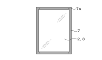
- FIG. 3 is a perspective view of a stacked window according to an embodiment of the present disclosure.
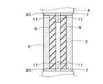
- Sectional drawing which shows the 1st example of the cross-sectional structure of the overlapping window of FIG.
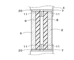
- Sectional drawing which shows the example from which the shape of a 1st frame differs from FIG.
- Sectional drawing which shows the 2nd example of the cross-sectional structure of the overlapping window of FIG.
- Sectional drawing which shows the 3rd example of the cross-sectional structure of the overlapping window of FIG.
- sequence structure of a 1st light control member and a 2nd light control member The figure which shows the example which piled up the 1st light control member and the 2nd light control member. The figure which shows the example which shifted the relative movement amount to the predetermined direction of the 1st light control member and the 2nd light control member from FIG. 5 only by the pitch.
- the figure explaining the angle correction mechanism of a 2nd translucent member The figure which shows the example which provides an operation button in a 1st frame and slides a 2nd adjustment member.
- Sectional drawing which shows the 6th modification of an overlapping window Sectional drawing which shows the 7th modification of an overlapping window.
- Sectional drawing which shows the 8th modification of an overlapping window Sectional drawing which shows the 1st modification of an overlapping window.
- Sectional drawing which shows the 4th modification of an overlapping window Sectional drawing which shows the 5th modification of an overlapping window.
- Sectional drawing which shows the example in which a 1st frame is joined to one side surface connected to the opening part of a structure. Sectional drawing which shows the 9th modification of an overlapping window. The figure which shows the example which assembles
- FIG. 22B is a cross-sectional view showing a modification of FIG. 22A. Sectional drawing which shows the 11th modification of an overlapping window.
- FIG. 23B is a cross-sectional view showing a modification of FIG. 23A. Sectional drawing which shows the 12th modification of an overlapping window. Sectional drawing which shows the 13th modification of an overlapping window.
- FIG. 27B is a cross-sectional view showing a modification of FIG. 27A. Sectional drawing of the overlapping window by 2nd Embodiment. The top view of the overlapping window by 2nd Embodiment.
- FIG. 28B is a cross-sectional view showing a modification of FIG. 28A.
- FIG. 28B is a cross-sectional view showing a modification of FIG. 28A.
- the “vertical direction” in this specification is a direction that is not parallel to the horizontal direction in a plane parallel to the vertical direction, and does not necessarily match the vertical direction.
- “Upper” means one side in the vertical direction and the side (or direction) close to “upper” in the vertical direction.
- “Lower” refers to a side (or direction) opposite to “upper” in the vertical direction and close to “lower” in the vertical direction.
- a “sheet” is a concept including a member that can be called a film or a plate.
- FIG. 1 is a perspective view of an overlapping window 1 according to the first embodiment of the present disclosure.
- An assembly kit 3 is assembled to the overlapping window 1 in FIG.
- the assembly kit 3 includes a first light transmissive member 2, a first light control member 8, and a second light control member 9.
- the first light control member 8 is supported, for example, bonded to the first light transmissive member 2.
- the second dimming member 9 When the second dimming member 9 is disposed at a position facing the first dimming member 8, the second dimming member 9 constitutes a dimming unit 19 together with the first dimming member 8.
- the light control unit 19 has different transmittances in the visible light wavelength region depending on the relative positions of the first light control member 8 and the second light control member 9 in the predetermined direction.
- the structure 1 can be assembled to a second light-transmissive member 6 such as an existing window glass to constitute the stacked window 1.
- the second light transmissive member 6 is disposed in the opening 5 of the structure 4 that partitions the first space sp1 and the second space sp2.
- the structure 4 is, for example, a building wall or a partition member. When the structure 4 is a wall of a building, one of the first space sp1 and the second space sp2 is an outer space of the building, and the other is an in-building space.
- the assembly kit 3 may include the first light transmissive member 2, the first frame 7, the first light control member 8, and the second light control member 9.
- the first light transmissive member 2 is disposed opposite to the second light transmissive member 6 when assembled, and is approximately the same size as the second light transmissive member 6.
- the first frame 7 is attached to the structure 4 and the first light transmissive member 2, and the first light transmissive member 2 is supported by the first frame 7 at a position facing the second light transmissive member 6. .
- the second light control member 9 is supported by the first light transmissive member 2, the second light transmissive member 6, or the first frame body 7.
- the first light control member 8 is supported by the first light transmitting member 2 or the first frame 7 so as to be capable of relative movement with respect to the second light control member 9.
- the transmittance in the visible wavelength range that transmits both the first light control member 8 and the second light control member 9 is the relative position of the first light control member 8 and the second light control member 9 in the predetermined direction da. Will change accordingly.
- the first light control member 8 and the second light control member 9 constitute a light control unit 19.
- the light control unit 19 has a transmittance in a visible light wavelength range that differs depending on the relative position between the first light control member 8 and the second light control member 9.
- FIG. 1 shows an example in which the first dimming member 8 and the second dimming member 9 are in close contact with each other, but as will be described later, the first dimming member 8 and the second dimming member 8 are arranged.
- the light control member 9 may be disposed to face the light control member 9 at a predetermined interval.
- the overlapping window 1 in FIG. 1 may be one in which three or more kinds of light-transmitting members are arranged to face each other.
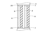
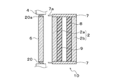
- FIG. 2A is a sectional view showing a first example of the sectional structure of the overlapping window 1 of FIG.
- the stacked window 1 in FIG. 2A has a second light control member 9 made of a light control film attached to one main surface of the second light transmissive member 6 made of a window glass previously set in the structure 4, and this first
- the first light transmissive member 2 is supported by a first frame 7 that is disposed so as to surround the opening of the structure 4.
- the second light transmissive member 6 is supported by a frame member 20 arranged so as to surround the opening of the structure 4. In the example of FIG. 2A, the first frame 7 and the frame member 20 are both joined to the structure 4.
- the magnet 11 is attached to a plurality of locations on the edge of the second light control member 9, and the magnet 11 is also attached to a plurality of locations on the edge of the first light control member 8.
- the first light transmissive member 2 is positioned with respect to the second light transmissive member 6 by bringing the magnet 11 at the edge of the second light control member 9 into contact with the magnet 11 at the edge of the first light control member 8. .
- a plurality of magnets 11 are attached to the edge of the first dimming member 8 along a predetermined direction da that is the front and back direction of the paper surface of FIG.
- the relative position of the first dimming member 8 and the second dimming member 9 in the predetermined direction da can be changed by making contact with the magnet 11 at the edge of 9.
- the first dimming member 8 and the second dimming member 9 are arranged to face each other, but a gap corresponding to the thickness of at least two magnets 11 is provided between the two dimming members 8 and 9. Is provided.
- a first frame 7 is attached around the first light transmissive member 2 to which the first light control member 8 is bonded, and the first light control member 8 and the second light control member 9 in a predetermined direction da.
- the first light control member 8, the first light transmissive member 2, and the first frame body 7 are moved together along the predetermined direction da. More specifically, in a state where the first dimming member 8 is moved away from the second dimming member 9 to a position where the second dimming member 9 is not attracted to the magnet 11, the first frame 7 and the first dimming member 9 are moved in the predetermined direction da.
- the first light transmissive member 2 is moved closer to the second light transmissive member 6 at a desired movement position, and the magnet 11 of the second light control member 9 and the magnet 11 of the first light control member 8 are brought into contact with each other. .
- a guide member for moving the first light control member 8 along the predetermined direction da may be provided separately, and the first light control member 8 may be slid in the predetermined direction da.
- the magnet 11 when the first frame 7 covers the magnet 11, the magnet 11 is observed when the second light transmissive member 6 side is observed from the first light transmissive member 2 side. Can be made invisible.
- the magnet 11 in FIGS. 2A and 2B only needs to have a magnetic force enough to maintain the adhesion of the light control members 8 and 9.
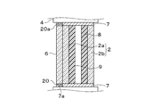
- FIG. 2C is a cross-sectional view showing a second example of the cross-sectional structure of the overlapping window 1 in FIG.
- the stacked window 1 in FIG. 2C has a second light control member 9 made of a light control film attached to one main surface of the second light transmissive member 6 made of a window glass previously set in the structure 4, and this first
- positioned by the 2 light control member 9 is shown.
- the first frame body 7 extends along the front and back direction of the paper surface, and the first light transmissive member 2 to which the first light control member 8 is bonded is formed along the first frame body 7 in a predetermined direction (paper surface). It can be moved in the front and back direction).
- the first frame body 7, the first light-transmissive member 2, and the first dimming member 8 are moved together.
- the first frame body 7 is The first light-transmissive member 2 and the first light-modulating member 8 are fixed to the structure 4 and are movable in a predetermined direction along the first frame body 7.
- the first dimming member 8 and the second dimming member 9 are arranged to face each other with a slight gap, and the gap between the first dimming member 8 and the second dimming member 9 is larger than that of the first example. It can be narrowed.
- the first frame body 7 is supported by at least one of the frame member 20 that supports the second light transmissive member 6 and the structure body 4.
- the visible light transmittance can be improved when the gap between the first dimming member 8 and the second dimming member 9 is as narrow as possible.
- the gap between the first dimming member 8 and the second dimming member 9 is large, these dimming members are observed when observed from the direction inclined from the normal direction of one main surface of the dimming members 8 and 9.
- a boundary surface between a first region and a second region, which will be described later, in the members 8 and 9 is easily visible.
- FIG. 2D is a cross-sectional view showing a third example of the cross-sectional structure of the overlapping window 1 of FIG.
- a second frame 12 is provided in addition to the structure of the second example.
- the second frame body 12 is disposed so as to surround the edge portions of the first light-transmissive member 2 and the first light-modulating member 8, and the second frame body 12, the first light-transmissive member 2, and the first light-modulating member. 8 is integrated and can be moved on the first frame 7 along a predetermined direction.
- the first frame body 7 is supported by at least one of the frame member 20 and the structure body 4.
- the sectional structure of the overlapping window 1 of the present disclosure is not limited to the above-described FIG. 2A, FIG. 2C, or FIG. 2D. Various cross-sectional structures described later may be used, or other cross-sectional structures may be used.
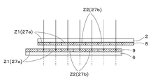
- FIG. 3 shows a cross-sectional structure of the first light transmissive member 2 to which the first light control member 8 is bonded and a cross-sectional structure of the second light transmissive member 6 to which the second light control member 9 is bonded.
- the cross-sectional structures of the first light control member 8 and the second light control member 9 are the same.
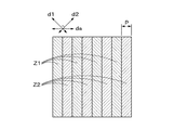
- each of the first dimming member 8 and the second dimming member 9 includes a first region Z1 and a second region Z2 that are repeatedly arranged in a predetermined direction da.
- the first region Z1 and the second region Z2 are repeatedly arranged at a constant pitch P in the predetermined direction da.
- the arrangement pitch P of the first region Z1 and the second region Z2 along the predetermined direction da is the same in the first dimming member 8 and the second dimming member 9.
- the second translucent member 6 and the second dimming member 9 are bonded and bonded via an adhesive layer 21.
- the adhesive layer 21 may contain an additive that provides light resistance.
- the second light control member 9 includes the first polarizing layer 33 and the first retardation film 25.
- the first light control member 8 includes a second polarizing layer 31 and a second retardation film 23.
- the first polarizing layer 31 has a first polarization axis
- the second polarizing layer 33 has a second polarization axis.
- the first retardation film 25 and the second retardation film 23 each have a plurality of first regions Z1 and second regions Z2 that are alternately arranged along a predetermined direction da.
- the adjacent first region Z1 and second region Z2 have different in-plane slow axis directions.
- the first polarizing layer 33 and the first retardation film 25 are bonded via an adhesive layer 35.
- the second polarizing layer 31 and the second retardation film 23 are bonded and bonded via an adhesive layer 35.
- a protective layer for preventing scratches may be formed on the surfaces of the first and second light control members 8 and 9.
- the second retardation film 23 is obtained by laminating the alignment layer 27 and the first liquid crystal layer 22 on the base material layer 26, and the first retardation film 25 is formed by aligning the alignment layer 27 on the base material layer 26.
- the second liquid crystal layer 24 is laminated.
- the base material layer 26 is formed using a transparent material having a small in-plane refractive index difference.
- a resin film having a thickness of 40 ⁇ m or more and 100 ⁇ m or less in particular, a film made of TAC (triacetyl cellulose), a film made of acrylic resin, a film of cycloolefin polymer, or the like can be used as the base material layer 26.
- the alignment layer 27 includes first alignment portions 27a and second alignment portions 27b that are alternately arranged along a predetermined direction da. Each first orientation portion 27a defines one first region Z1, and each second orientation portion 27b defines one second region Z2.
- the arrangement pitch of the first orientation part 27a and the second orientation part 27b in the predetermined direction da is such that the first light control member 9 and the first light control member 8 have the first region Z1 and the second region Z2 in the predetermined direction da. It is the same as the arrangement pitch.
- intersects, and an intersection angle is a right angle, for example.
- the first liquid crystal layer 22 and the second liquid crystal layer 24 each have a first liquid crystal unit 29a and a second liquid crystal unit 29b.
- the first liquid crystal unit 29 a is disposed on the first alignment unit 27 a of the alignment layer 27, and the second liquid crystal unit 29 b is disposed on the second alignment unit 27 b of the alignment layer 27. Accordingly, each first liquid crystal unit 29a is positioned corresponding to one first region Z1, and each second liquid crystal unit 29b is positioned corresponding to one second region Z2.
- the first liquid crystal layer 22 and the second liquid crystal layer 24 each include molecules aligned by the alignment regulating force of the alignment layer 27. Since the alignment layer 27 expresses an alignment regulating force in a direction intersecting with each other between the first alignment portion 27a and the second alignment portion 27b, the molecules contained in the first liquid crystal portion 29a and the second liquid crystal portion 29b are Are oriented in different directions, in particular in orthogonal directions. Each of the liquid crystal units 29a and 29b has a slow axis in a direction corresponding to the alignment direction of the molecules, for example, in a direction orthogonal to the direction in which the molecules are aligned.
- the slow axis direction d1 in the first liquid crystal unit 29a corresponding to the first region Z1 and the slow axis direction d2 in the second liquid crystal unit 29b corresponding to the second region Z2 intersect each other. In particular, they become orthogonal.
- each first region Z1 of the second dimming member 9 faces one of the first regions Z1 of the first dimming member 8, and each second region Z2 of the second dimming member 9 is When facing any second region Z ⁇ b> 2 of the first light control member 8, the light transmitted through the second light control member 9 can pass through the first light control member 8. More specifically, the light of one linearly polarized light component transmitted through the first region Z1 of the second dimming member 9 enters the first region Z1 of the first dimming member 8, and the first dimming member 8 Of the first region Z1.
- the light of the other linearly polarized light component that has passed through the second region Z2 of the second light control member 9 is incident on the second region Z2 of the first light control member 8, and the second light of the first light control member 8 is second.
- the region Z2 is transmitted.
- region Z1 of the 2nd light control member 9 faces any 2nd area
- region Z2 of the 2nd light control member 9 is 1st light control. It comes to face one of the first regions Z1 of the member 8. In this state, the light transmitted through the second light control member 9 cannot be transmitted through the first light control member 8 and is absorbed by the first light control member 8.
- the light of one linearly polarized light component transmitted through the first region Z1 of the second dimming member 9 enters the second region Z2 of the first dimming member 8, and the first dimming member 8 Is absorbed in the second region Z2.
- the light of the other linearly polarized light component that has passed through the second region Z2 of the second light control member 9 is incident on the first region Z1 of the first light control member 8, and the second light of the first light control member 8 is second. Absorbed in region Z2.
- a transmission state (FIG. 5) that transmits visible light and a light shielding that blocks visible light. It can be switched to the state (FIG. 6).
- the light can be easily and immediately adjusted by simply sliding the second light adjusting member 9 and the first light adjusting member 8 relative to each other.
- the first dimming member 8 and the second dimming member 9 having the structure shown in FIGS. 3 to 6 are switched by the relative movement in the predetermined direction da by the pitch, thereby switching whether to transmit visible light.
- the first dimming member 8 and the first dimming member 8 having a structure capable of switching the transmittance of visible light in multiple steps according to the relative movement amount of the first dimming member 8 and the second dimming member 9 in the predetermined direction da.
- a dimming member 9 may be provided.
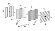
- the first light control member 8 includes a first polarizing layer 31 and a first retardation film 32.
- the second light control member 9 includes a second polarizing layer 33 and a second retardation film 34.
- the first phase difference film 32 and the second phase difference film 34 are disposed close to and opposed to each other.
- the first polarizing layer 31 and the second polarizing layer 33 are not essentially different from the polarizing layers 22 and 24 described in FIG.
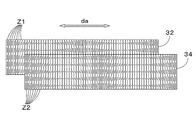
- FIG. 8 is a schematic plan view showing an example of each of the retardation films 32 and 34.
- the first retardation film 32 includes a plurality of first regions Z1 arranged along a predetermined direction da.
- the second retardation film 34 also includes a plurality of second regions Z2 arranged along the predetermined direction da.
- Each of the plurality of regions Z1 and Z2 is configured such that the direction of the in-plane slow axis changes stepwise along a predetermined direction da.
- region Z1, Z2 of FIG. 8 has shown the direction of the in-plane slow axis in the said area
- the direction of the slow axis in each region Z1, Z2 is constant. That is, in the retardation films 32 and 34, the direction of the slow axis in each of the regions Z1 and Z2 changes along the predetermined direction da, but each of the regions Z1 and Z1 along the direction orthogonal to the predetermined direction da. The direction of the slow axis in Z2 is aligned.
- the light of one linearly polarized light component transmitted through the first polarizing layer 31 passes through the first retardation film 32 and the second retardation film 34 and travels toward the second polarizing layer 33.
- the phase of the light transmitted through the first retardation film 32 is changed by a phase modulation amount corresponding to the direction of the slow axis of the first region Z1 to be transmitted.
- the light transmitted through the second retardation film 34 has a phase corresponding to the polarization state after passing through the first retardation film 32 and the direction of the slow axis of the second region Z2 to be transmitted.
- the phase can be changed by the modulation amount.
- the polarization state after passing through the first retardation film 32 and the second retardation film 34 is obtained by adding the phase modulation amount exerted from the first retardation film 32 and the phase modulation amount exerted from the second retardation film 34. It is controlled, and the transmittance of the second polarizing layer 33 incident thereafter changes according to the polarization state.
- the retardation films 32 and 34 are layers that give a retardation of ⁇ / 2.
- light of a linearly polarized component that vibrates in the same direction as the vertical direction that is the polarization axis direction of the first polarizing layer 31 is transmitted through the first polarizing layer 31.
- the light transmitted through the first polarizing layer 31 is divided by 2 ⁇ ⁇ 1 when the angle between the vibration direction of the linearly polarized light and the slow axis of the first retardation film 32 is ⁇ 1 by the first retardation film 32. Rotate.
- the light transmitted through the first retardation film 32 is 2 ⁇ ⁇ 2 when the angle between the vibration direction of the linearly polarized light and the slow axis of the second retardation film 34 is ⁇ 2 by the second retardation film 34. Rotate minutes.
- the light that vibrates in the vertical direction after passing through the first polarizing layer 31 is changed to light that vibrates in the horizontal direction by the phase modulation function of the two retardation films 32 and 34.
- the second polarizing layer 33 is transmitted. That is, in the example of FIG. 9, the light transmitted through the first polarizing layer 31 is transmitted through the second polarizing layer 33 with a transmittance of 100% by design.
- the incident light is non-polarized light
- the transmittance of the first polarizing layer 31 is 50%. Therefore, the transmittance of the overlapping window 1 shown in FIG. 9 is ideally 50%.
- the second retardation film 34 is moved relative to the first retardation film 32 in a predetermined direction da, so that the first region through which incident light is to be transmitted.
- the transmittance of the overlapping window 1 can be adjusted by changing the combination of Z1 and the second region Z2.
- the polarizing layers 31 and 33 are not shown.
- the assembly kit 3 of the overlapping window 1 is assembled to the second light transmissive member 6 that is installed in the structure 4 in advance. At that time, unless the first dimming member 8 and the second dimming member 9 face each other at the correct position and angle, the transmittance cannot be adjusted correctly by relative movement. In particular, when the first light transmissive member 2 is assembled, the angle with the second light transmissive member 6 may be shifted. Therefore, the assembly kit 3 may be provided with an angle correction function of the first light transmissive member 2.
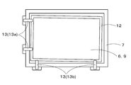
- FIG. 10 is a diagram illustrating an angle correction mechanism of the first light transmissive member 2.
- the assembly kit 3 in FIG. 10 includes a first frame 7 that supports the first light transmissive member 2 at a position facing the second light transmissive member 6, and a first light transmissive member in which the first light control member 8 is bonded.
- the second frame 12 attached to the edge of the second frame 12 and an angle correction member 13 for correcting the angle of the second frame 12 are provided.
- the angle correction member 13 includes a plurality of pins 13 a and 13 b that penetrate the first frame body 7.
- the plurality of pins 13 a and 13 b are provided to face a plurality of surfaces of the second frame 12.
- the angle of the second frame body 12 can be corrected by adjusting the amount by which the surface of the second frame body 12 is pushed in by the tips of the pins 13a and 13b.
- the angle correction member 13 is on the lower surface where the weight of the frame body 12 is applied.
- the example which provides the pin 13b in two places of the lower surface of the 2nd frame 12 is shown, However, The number of the pins 13b is arbitrary.
- at least a part of the angle correction member 13 (pin 13a) can perform a positional deviation correction in the left-right direction when the angle is adjusted with the pin 13b on the lower surface side of the second frame body 12.
- the pin 13a is provided only on the left end side of the second frame 12, but the pin 13a may also be provided on the right end side. If the pins 13a are provided on the left and right end sides of the second frame body 12, the first and second light control members 8 and 9 can be finely adjusted by one operation amount along the operation direction.
- operation buttons 14 may be provided on the first frame 7 as shown in FIG.
- the first light transmissive member 2 to which the first dimming member 8 is attached can be moved in the operation direction of the operation button 14 by manipulating the operation button 14 in the predetermined direction da.
- the operation amount of the operation button 14 may be only one pitch in FIG. Thereby, it can switch whether visible light is allowed to pass or not.
- the visible light transmittance of the dimming unit 19 including the first dimming member 8 and the second dimming member 9 is multi-staged according to the operation amount of the operation button 14. You can switch to
- FIG. 11 shows an example in which the operation button 14 is provided on the lower edge of the frame body, but the location of the operation button 14 is arbitrary. For example, you may provide in the upper part of a frame, the right or left edge, or another place.
- the overlapping window 1 is formed by assembling the second light-modulating member 9, the first light-transmitting member 2, and the first light-modulating member 8 to the existing second light-transmitting member 6.
- a plurality of modifications can be considered as one specific structure.
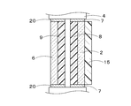
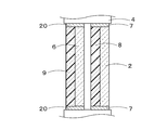
- FIG. 12 is a cross-sectional view showing a first modification of the overlapping window 1.
- the overlapping window 1 in FIG. 12 includes a second light-modulating member 9 that is bonded to a second light-transmitting member 6 that has been installed in the structure 4 in advance, and a first light-transmitting member that is bonded to the first light-modulating member 8. 2 and a first frame 7 surrounding the edge of the first light-transmissive member 2.
- the visible light transmittance passing through the first dimming member 8 and the second dimming member 9 can be switched between two stages or multiple stages.
- the second frame 12 in FIG. 12 is arranged on the indoor side of the building. Thereby, visible light transmittance can be adjusted by moving the 1st light control member 8 in the predetermined direction da, without opening and closing the 2nd translucent member 6. As shown in FIG.
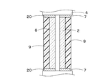
- FIG. 13 is a cross-sectional view showing a second modification of the overlapping window 1.
- the overlapping window 1 in FIG. 13 has a functional film 15 disposed on the surface opposite to the bonding surface of the first light control member 8 of the first light transmissive member 2.
- An example is shown.
- the structural body 4 is an outer wall of a building
- the functional film 15 in FIG. 13 is disposed on the indoor side. Therefore, even if the first light-transmissive member 2 is broken for some reason, the fragments are not scattered and safety is improved. improves.
- the functional film 15 may be a scattering prevention film that prevents scattering of fragments when the first light transmissive member 2 is broken, or may be a hard coat film that prevents the surface of the first light transmissive member 2 from being damaged. And the antifouling film which prevents that filth adheres to the surface of the 1st translucent member 2 may be sufficient, and the antireflection film which prevents an observer's reflection may be sufficient.
- FIG. 14 is a cross-sectional view showing a third modification of the overlapping window 1.
- the arrangement place of the first light control member 8 is changed to the opposite surface side instead of the surface of the first light transmitting member 2 on the second light adjustment member 9 side.
- the first light control member 8 performs substantially the same function as the functional film 15 of FIG.
- the distance between the first dimming member 8 and the second dimming member 9 may be wider than that in FIG.
- FIG. 15 is a cross-sectional view showing a fourth modification of the overlapping window 1.
- the overlapping window 1 in FIG. 15 is opposite to the first modification example in FIG. 12 in that the second light control member 9 is disposed not on the surface of the second light transmission member 6 on the first light control member 8 side. It has been changed to the surface side.
- the second light control member 9 performs a function substantially equivalent to that of the functional film 15. Therefore, even when the second light transmitting member 6 is broken for some reason, it is possible to prevent the fragments from scattering to the second light control member 9 side.
- the distance between the second light control member 9 and the first light control member 8 may be wider than that in FIG. 12.
- FIG. 16 is a cross-sectional view showing a fifth modification of the overlapping window 1.
- the functional film 15 is arranged on the surface side opposite to the bonding surface of the first light control member 8 of the first light transmissive member 2 with respect to the fourth modification example in FIG. 15. Is.
- the overlapping window 1 of FIG. 16 can prevent that the fragment
- FIG. 17 is a cross-sectional view showing a sixth modification of the overlapping window 1. 17 overlaps the 1st light control member 8 and the arrangement surface of the 2nd light control member 9 with respect to the 1st modification of FIG. That is, in the overlapping window 1 in FIG. 17, the second light control member 9 is bonded to the surface of the second light transmission member 6 opposite to the surface facing the first light transmission member 2, and the first light control member 8. Is bonded to the surface of the first light transmissive member 2 opposite to the surface facing the second light transmissive member 6. In the overlapping window 1 in FIG. 17, even if the second light transmitting member 6 is broken, the second light adjusting member 9 can prevent the fragments from scattering to the second light adjusting member 9 side. Even if the 1st translucent member 2 cracks, it can prevent that the fragment
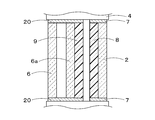
- FIG. 18 is a cross-sectional view showing a seventh modification of the overlapping window 1.
- the overlapping window 1 in FIG. 18 shows an example of a triple window.
- the window glass previously installed in the structure 4 is a double window such as a pair glass or a laminated glass including the second light transmitting member 6 and the third light transmitting member 6a
- the assembly kit 3 according to this embodiment is assembled, a triple window is completed.
- the overlapping window 1 of FIG. 18 while the 2nd light control member 9 is stuck on the 3rd light transmission member 6a of a double window structure, the 1st light transmission member 2 on which the 1st light control member 8 was bonded together is 2nd.
- the light control member 9 and the first light control member 8 are assembled so as to face each other.
- the first light control member 2 is arranged in a direction inclined with respect to the normal direction of the first light transmission member 2. Even if the 1 translucent member 2 is observed, the possibility that the boundary surface between the first region Z1 and the second region Z2 is visually recognized in the gap between the first dimming member 8 and the second dimming member 9 is reduced.
- FIG. 19A is a cross-sectional view showing an eighth modification of the overlapping window 1.
- the overlapping window 1 in FIG. 19A also shows an example of a triple window.
- the assembly kit 3 has a double window structure, and the first light transmissive member 2 in the assembly kit 3 has two light transmissive members 2a and 2b that are spaced apart from each other.
- the second light control member 9 is bonded to one of the light transmitting members 2a, and the first light control member 8 is bonded to the other light transmitting member 2b.
- the second dimming member 9 and the first dimming member 8 are disposed adjacent to each other.
- the second dimming member 9 and the first dimming member 8 can be moved relative to one pitch. More specifically, at least one of the first translucent member 2 to which the first dimming member 8 is bonded and the second translucent member 6 to which the second dimming member 9 is bonded is the first frame body. 7 can be moved relative to the front and back of the paper by one pitch.
- FIG. 20 is a cross-sectional view showing a ninth modification of the overlapping window 1.
- the overlapping window 1 in FIG. 20 also shows an example of a triple window.
- the window glass previously set in the structure 4 is a pair glass in which two light transmitting members (second light transmitting member 6 and third light transmitting member 6a) are arranged separately.
- the second light control member 9 is attached to one light transmission member constituting the pair glass, and the first light transmission member 2 to which the first light adjustment member 8 is bonded is assembled.
- the overlapping window 1 of FIG. 20 has three separated structures.
- the assembly kit 3 according to the present embodiment can be assembled to an arbitrary second light transmissive member 6 installed in the structure 4, and the structure of the second light transmissive member 6 is not limited. This can also be applied to the overlapping window 1 having the structure described above.
- the window 1 shown in FIGS. 12 to 20 is not only assembled to the window glass provided on the building wall, but also to the glass provided on the partition plate 16 used for the partition inside the building as shown in FIG. It is also possible. Or you may assemble
- the assembly kit 3 When mounting, the assembly kit 3 preferably fits within the width of the opening of the structure 4, but at least a part of the assembly kit 3 may protrude from the width of the opening of the structure 4. Further, in the case of a bay window type in which the second light transmissive member 6 protrudes outside the opening of the structure 4, the assembly kit 3 does not protrude from the structure 4 by attaching the assembly kit 3 within the width of the opening. There is no risk of the assembly kit 3 hitting a human or the like.
- At least one of the first light transmissive member 2 and the second light transmissive member 6 constituting the overlapping window 1 manufactured by the assembly kit 3 according to the present embodiment may be Low-E glass.
- Low-E glass is a glass having a low radiation function by coating a glass with a special metal film such as silver.
- heat insulation performance and heat insulation performance can be improved.
- the first light transmissive member 2 constituting the assembly kit 3 is made Low-E glass, so that the second The heat insulation performance and the heat shielding performance can be improved without exchanging the translucent member 6.
- the overlapping window 1 can easily switch the visible light transmittance by changing the relative position between the first light control member 8 and the second light control member 9, and does not consume power. Can be handled.
- the visible light transmittance can be switched between two stages and multiple stages, and the light can be adjusted according to the application.
- An assembly kit 3 can be provided. By providing the first light transmissive member 2 with a handle slidable in the direction da in FIG. 1, the relative position between the first light control member 8 and the second light control member 9 can be easily changed.
- the visible light transmittance of the first dimming member 8 and the second dimming member 9 can be switched between two stages and multiple stages.
- the shape of the handle for example, a structure in which a plate-like or rod-like transparent body (glass) is bonded to the surface via an adhesive, or a structure in which a part of the light-transmitting member inside the room is processed into a concave shape is conceivable. .
- the assembly kit 3 having the first light control member 8 and the second light control member 9 is attached to the second light transmission member 6 made of an existing window glass or the like without attaching the light control film.
- An example in which the two light transmissive members 6 are arranged in proximity is shown.
- the light control device 10 having the first light control member 8 and the second light control member 9 is disposed in proximity to the existing second light transmission member 6, thereby The light member 6 can have a dimming function.
- the first dimming member 8 and the second dimming member 9 are accommodated within the width of the opening of the structure 4 so that the assembly kit 3 does not protrude to the outside of the structure 4. It is possible to prevent 3 from hitting something (for example, a human).
- FIG. 19B shows an example in which the first frame 7 is bent by approximately 90 degrees, and the first frame 7 is joined to one side surface that is continuous with the opening of the structure 4.
- the assembly kit 3 is within the width of the opening of the structure 4, and there is no possibility that the assembly kit 3 will hit anything.
- FIG. 22A is a cross-sectional view showing a tenth modification of the overlapping window 1.
- the overlapping window 1 in FIG. 22A includes a light control device 10 having a double window structure.
- the light control device 10 is disposed in the vicinity of the second light transmissive member 6 made of an existing window glass or the like.
- the dimming device 10 in FIG. 22A is similar to the assembly kit 3 in FIG. 19A in that two translucent members 2a and 2b, a second dimming member 9 bonded to one translucent member 2a, and the other It has the 1st light control member 8 bonded by the translucent member 2b.
- the first dimming member 8 and the second dimming member 9 of the dimming device 10 can switch the overlapping state of the opposing surfaces to two stages or multiple stages. Thereby, the transmittance
- FIG. 22A shows an example in which the joint protrusion 7a and the joint receiver 20a are provided at a plurality of locations, but the number of the joint protrusion 7a and the joint receiver 20a is not particularly limited.
- positioning location of the joining projection part 7a and the joining receiving part 20a are arbitrary.
- the joint protrusion 7a may have a shape that continuously extends in the front and back direction of the paper.
- the light control device 10 of FIG. 22A can change the overlapping condition of the opposing surfaces of the first light control member 8 and the second light control member 9 in two steps or in multiple steps. Thereby, the transmittance
- the degree of overlap between the opposing surfaces of the first dimming member 8 and the second dimming member 9 was such that the translucent member 2b to which the first dimming member 8 was bonded and the second dimming member 9 were bonded.
- the relative position with respect to the translucent member 2a can be changed by shifting by the pitch P in FIG.
- the light control device 10 can be firmly fixed to the structure 4 by fitting the joint protrusion 7 a of the light control device 10 to the joint receiving portion 20 a of the structure 4. Further, by making the joining projection 7a detachable such as a screw or the like, the light control device 10 can be attached and detached. For example, if a problem occurs in the light control device 10, a new light control device 10 is provided. It becomes easy to perform replacement work.
- the second light transmissive member 6 breaks or the frame member 20 is broken, the second light transmissive member 6 or the frame member 20 may be replaced after removing the light control device 20 once. Since it becomes easy, maintenance cost can be suppressed.
- joint receiving portion 20a of the light control device 10 can be provided by post-processing.
- a through-hole can be provided in the frame body 7 and a joint projection 7a such as a screw can be provided, so that the light adjustment device 10 can be easily attached.
- FIG. 22A shows an example in which the light control device 10 protrudes from the width of the opening of the structure 4. However, as shown in FIG. 22B, the second light-transmitting light is within the width of the opening of the structure 4.
- the member 6 and the light control device 10 may be accommodated.
- FIG. 23A is a cross-sectional view showing an eleventh modification of the overlapped window 1, and shows an example in which the bonding projection 7a and the bonding receiving portion 20a are provided in a direction different from FIG. 22A by 90 degrees.
- the extending direction of the bonding protrusion 7a in FIG. 23A is 90 degrees different from the extending direction of the bonding protrusion 7a in FIG. 22A.
- the structure provided with both the joint projection part 7a and the joint receiving part 20a of FIG. 22A, and the joint projection part 7a and the joint receiving part 20a of FIG. 23A is also considered.
- the light-adjusting device 10 By fitting the light-adjusting device 10 to the structural body 4 by fitting the joint protrusion 7a to the joint receiving portion 20a, the light-adjusting device 10 can be firmly adjusted without being affected by shaking or rattling of the frame member 20 or the second light-transmissive member 6.
- the optical device 10 can be attached. Further, after the light control device 10 is attached to the structure 4, the joint protrusion 7a can be removed from the joint receiving portion 20a, and the light control device 20 is attached and detached in the same procedure as the attachment and removal of the window sash. It can be performed.
- FIG. 23A shows an example in which the light control device 10 protrudes from the width of the opening of the structure 4. However, as shown in FIG. 23B, the second light transmission device falls within the width of the opening of the structure 4. The member 6 and the light control device 10 may be accommodated.
- FIG. 24 is a cross-sectional view showing a twelfth modification of the overlapping window 1. 24 overlaps the light control apparatus 10 via the adhesive member 37 to the side surface of the pushing edge 36 provided in the peripheral part of the 2nd translucent member 6, such as the existing window glass.
- the light control device 10 can be installed without drilling the frame member 20 or the like. Thereby, the light control device 10 can be bonded to the structure 4 according to the size of the opening of the structure 4 by adjusting the position where the push edge 36 is bonded to the light control device 10.
- FIG. 25 is a cross-sectional view showing a thirteenth modification of the overlapping window 1.
- the overlapping window 1 in FIG. 25 is obtained by adhering the light control device 10 via an adhesive member 37 to a structure 4 into which a second light transmissive member 6 such as an existing window glass is fitted.
- the size of the translucent member constituting the light control device 10 is larger than the size of the second translucent member 6 made of an existing window glass or the like.
- the light control device 10 can be disposed without sacrificing the light transmission area of the existing second light transmission member 6, and the view area does not change before and after the installation. . Therefore, the light control device 10 having a size larger than that of the second light transmissive member 6 can be attached, and the mass productivity of the light control device 10 is improved.
- the light control device 10 is supported only by the adhesive member 37. If the weight of the light control device 10 is large, the supporting force may be insufficient. In this case, for example, as shown in FIG. 25, it is desirable to provide a support body 38 having one end joined to the structure 4 and to support the light control device 10 by this support body 38.
- 22 to 25 show an example in which the light control device 10 is installed in the vicinity of the second light transmitting member 6 without attaching the light adjusting member to the second light transmitting member 6 made of an existing window glass or the like. Although shown, while adhering the 2nd light control member 9 to the 2nd light transmission member 6, you may install the light control apparatus 10 provided with the 1st light control member 8 in proximity.
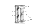
- FIG. 26A is a sectional view showing a fourteenth modification of the overlapping window 1
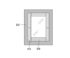
- FIG. 26B is a plan view of the overlapping window 1 of FIG. 26A.
- the stacked window 1 according to the fourteenth modification is a first transparent member in which the second light control member 9 is bonded to the second light transmission member 6 made of an existing window glass or the like, and the first light control member 8 is bonded.
- the light control device 10 having the light member 2 is disposed close to the second light transmissive member 6.
- a guide member 39 is provided on two opposite sides of the light control device 10.
- the guide member 39 extends in the front and back direction in FIG. 26A, and extends in the left-right direction in FIG. 26B.
- the first light-transmissive member 2 and the first light-modulating member 8 are movable along the guide member 39 by a predetermined amount in the front and back direction of the paper surface. Thereby, the overlapping degree of the opposing surfaces of the 1st light control member 8 and the 2nd light control member 9 can be switched to a two-step or multistep, and it has enabled it to adjust the transmittance
- the predetermined amount is the pitch P shown in FIG.
- both end sides of the two guide members 39 are arranged so that the edge of the first light transmissive member 2 does not appear in the appearance when the first light transmissive member 2 is moved along the guide member 39.
- the concealing member 40 is arranged on the surface. Thereby, when the 1st translucent member 2 is moved, the transmittance
- the concealing member 40 may be constituted by a push edge 36, for example.
- the light control device 10 may be provided with an angle correction function similar to that in FIG. Since the angle correction function is provided in the light control device 10, the second light control member 9 bonded to the second light transmissive member 6 made of an existing window glass or the like is not moved, and the first light control device 10 in the light control device 10 is moved. The angle of the translucent member 2 and the first dimming member 8 is adjusted.
- FIG. 27A is a cross-sectional view showing a fifteenth modification of the overlapping window 1
- FIG. 27B is a plan view in a state where the second light control member 9 is bonded to the second light transmitting member 6 of FIG. 27A
- FIG. 27C is FIG.
- FIG. 27D is sectional drawing which shows one modification of FIG. 27A.
- the frame member 7 that supports the first light transmissive member 2 is provided with a joint protrusion 7a.
- the joint projection 7a can be moved by the pitch P in a state where the joint projection 7a is fitted to the joint receiving portion 20a of the frame member 20 that supports the second light transmissive member 6.
- the overlapping state of the first light control member 8 and the second light control member 9 can be switched between two steps or multiple steps, and the transmittance of the overlapping window can be adjusted.
- the overlapping window 1 of the fifteenth modification shown in FIGS. 27A to 27C also has the same angle adjustment function as that in FIG. 10 in the light control device 1 including the first light transmitting member 2 and the first light control member 8. May be provided.
- the joint projection 7a is movable by one pitch in a state where the joint projection 7a is fitted to the joint receiver 20a.
- the one frame 7 may be fixed to the structure 4 so that the first dimming member 8 and the second dimming member 9 can be moved relative to each other along the first frame 7 by one pitch.
- the joining projection 7a may be a detachable structure such as a screw.
- FIG. 27A shows an example in which the light control device 10 protrudes from the width of the opening of the structure 4. However, as shown in FIG. 27D, the second light transmitting device 10 falls within the width of the opening of the structure 4. The member 6 and the light control device 10 may be accommodated.
- the assembly window 3 or the light control apparatus 10 is assembled
- the overlapping window 1 is produced using the existing second light-transmissive member 6 as it is, the installation work is easy and the equipment cost can be suppressed.
- the assembly kit 3 or the dimming device 10 of the present embodiment can be used even in the case of producing a retrofitted double window in a cold region or the like, and the overlapping window 1 with a dimming function can be produced without much cost. it can.
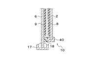
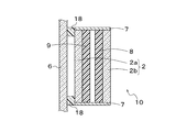
- FIG. 28A is a sectional view of the overlapping window 1 according to the second embodiment
- FIG. 28B is a plan view.
- the overlapping window 1 according to the second embodiment includes a light control device 10 having a first light transmitting member 2 in which a first light adjusting member 8 is bonded to a second light transmitting member 6 made of an existing window glass or the like. It is to be attached directly.
- the second light transmissive member 6 is fitted in the sash 17, and the second light transmissive member 6 is bonded to the second light transmissive member 6.
- the light control device 10 is bonded via an adhesive member 18.
- the first light-transmissive member 2 and the first light-modulating member 8 in the light control device 10 are movable by a pitch P in FIG.
- a concealing member 40 that covers the movement range of the edge of the first light transmissive member 2 is provided so that the edge of the first light transmissive member 2 does not appear on the appearance (see FIG. 28B).
- the second dimming member 9 is bonded above the adhesive member 18, but the second dimming member 9 may also be bonded below the adhesive member 18. Thereby, leakage of light from below the adhesive member 18 can be prevented.
- the gap between the sash 17 and the adhesive member 18 may be filled with a sealing material. desirable.
- the light control device 1 including the first light transmitting member 2 and the first light control member 8 may be provided with an angle adjustment function similar to that in FIG. .
- the light control apparatus 10 can be directly attached to 2nd light transmissive members 6, such as the existing window glass, and the light control apparatus 10 can be easily attached to the existing window glass. Can be retrofitted.
- FIG. 28C when the second light transmissive member 6 is attached to the opening of the structural body 4 almost flush with each other, the second light transmissive member 6 is attached to the periphery of the second light transmissive member 6 via the adhesive member 18.
- the 1 translucent member 2 may be attached. Further, as shown in FIG. 28D, an assembly having the same structure as FIG.
- Kit 3 (light control device 10) may be connected. Thereby, the light control apparatus 10 can be easily installed in the existing window etc.
- the existing building in order to attach the light control device 10 to the existing second light transmitting member 6 through the adhesive member 18, the existing building is provided with a screw hole or the light control device 10 side. It is not necessary to form protrusions on the window, and the structure of the overlapping window 1 can be simplified.
- the adhesive force of the adhesive member 18 is strong and the adhesive member 18 cannot be peeled from the second light transmissive member 6, the original state can be restored by replacing the second light transmissive member 6.
- the adhesive member 18 is attached to the first light transmitting member 2, but the light control device 10 may be attached to the sash 17 via the adhesive member 18.
- 1 stacking window 2 1st translucent member, 3 assembly kit, 4 structure, 5 opening, 6 2nd translucent member, 7 1st frame, 8 1st dimming member, 9 2nd dimming member, 11 magnet, 21 adhesive layer, 22 first liquid crystal layer, 23 first retardation film, 24 second liquid crystal layer, 25 second retardation film, 26 base layer, 27 orientation layer, 27a first orientation portion, 27b first 2 orientation part, 29a 1st liquid crystal part, 29b 2nd liquid crystal part, 31 1st polarizing layer, 32 1st retardation film, 33 2nd polarizing layer, 34 2nd retardation film, 35 adhesion layer
Landscapes
- Physics & Mathematics (AREA)
- General Physics & Mathematics (AREA)
- Optics & Photonics (AREA)
- Engineering & Computer Science (AREA)
- Structural Engineering (AREA)
- Civil Engineering (AREA)
- Architecture (AREA)
- Liquid Crystal (AREA)
Abstract
組立キット1は、第1空間と第2空間とを区画する構造体4の開口部5に配置された第1透光部材2との組み合わせで重ね窓1を組み立てるための重ね窓の組立キットであって、第2透光部材6と、第2透光部材を第1透光部材に対面する位置に支持する第1枠体7と、第1透光部材2、第2透光部材6又は第1枠体に支持される第1調光部材8と、第1調光部材に対して所定方向に相対動作可能に、第2透光部材又は第1枠体に支持される第2調光部材9と、を備える。第1調光部材および第2調光部材のそれぞれは、第1調光部材および第2調光部材の相対位置に応じて異なる可視光波長域の透過率を有する。
Description
本開示は、重ね窓の組立キット、重ね窓、構造体、調光装置、建物、調光キット、窓、車両および重ね窓の製造方法に関する。
透過率を調整可能な調光装置が提案されている。従前の調光装置は、電圧を調整して透過率を連続的または段階的に調整するものであり、電圧を調整する電源装置や、電源装置に接続するケーブルなどが必要となる。このため、装置が大がかりになり、消費電力が増大する上に、設備コストもかかるという問題がある。また、透過率を瞬時に切り替えることができないという不具合もある。
一方、特開平9-310567には、外界から屋内に入射する光量をわずかなスライド操作で調節可能な調光装置が開示されている。この調光装置は、外部電源を必要とせずに、調光を行えるようにしている。
しかしながら、特開平9-310567に開示された調光装置は、屋根等の外光入射部位の建材としての利用を念頭に置いており、既存の窓ガラスに取り付けることは意図していない。既存の窓ガラスに調光装置を取り付けるには、窓ガラス自体が調光装置の一部を構成することになるため、特開平9-310567の調光装置をそのまま適用するのは容易ではない。
特に、冬の寒さが厳しい地域などでは、既存の窓ガラスに別の窓ガラスを追加で取り付けて二重窓や三重窓にする工事を行うことがある。その際に、調光機能を持たせることができれば、既存の窓ガラスを取り外して、調光機能付きの高価な二重窓などを取り付けるよりも、費用面と工期短縮の面からも望ましい。
本開示は、上述した点を考慮してなされたものであり、既存の窓ガラス等の透光部材に簡易に取り付け可能な重ね窓の組立キット、重ね窓、構造体、調光装置、建物、調光キット、窓、車両および重ね窓の製造方法を提供するものである。
[課題を解決するための手段]
上記の課題を解決するために、本開示の一態様では、第1透光部材と、
前記第1透光部材に支持される第1調光部材と、
前記第1調光部材に対面する位置に配置されたときに、前記第1調光部材とともに調光部を構成する第2調光部材と、を備え、
前記調光部は、前記第1調光部材および前記第2調光部材の所定方向における相対位置に応じて異なる可視光波長域の透過率を有する、重ね窓の組立キットが提供される。
上記の課題を解決するために、本開示の一態様では、第1透光部材と、
前記第1透光部材に支持される第1調光部材と、
前記第1調光部材に対面する位置に配置されたときに、前記第1調光部材とともに調光部を構成する第2調光部材と、を備え、
前記調光部は、前記第1調光部材および前記第2調光部材の所定方向における相対位置に応じて異なる可視光波長域の透過率を有する、重ね窓の組立キットが提供される。
第1空間と第2空間とを区画する構造体の開口部に配置された第2透光部材に対面する位置に前記第1透光部材を支持する第1枠体を備えてもよく、
前記第2調光部材は、前記第1調光部材に対して所定方向に相対動作可能に、前記第1透光部材又は前記第1枠体に支持されてもよい。
前記第2調光部材は、前記第1調光部材に対して所定方向に相対動作可能に、前記第1透光部材又は前記第1枠体に支持されてもよい。
前記第1枠体は、前記第2透光部材を支持する枠部材および前記構造体の少なくとも一方に取り付け可能となっていてもよい。
前記第1調光部材は、前記第1透光部材によって前記第1透光部材の前記第2透光部材側に支持され、
前記第2調光部材は、前記第1透光部材によって前記第2透光部材の前記第1透光部材側に支持されてもよい。
前記第2調光部材は、前記第1透光部材によって前記第2透光部材の前記第1透光部材側に支持されてもよい。
前記第1調光部材は、前記第1透光部材によって前記第1透光部材の前記第2透光部材側に支持され、
前記第2調光部材は、前記第2透光部材によって前記第2透光部材の前記第1透光部材側に支持され、
前記第1透光部材によって、前記第1透光部材の前記第2透光部材とは反対側に支持される飛散防止層を更に備えてもよい。
前記第2調光部材は、前記第2透光部材によって前記第2透光部材の前記第1透光部材側に支持され、
前記第1透光部材によって、前記第1透光部材の前記第2透光部材とは反対側に支持される飛散防止層を更に備えてもよい。
前記第1調光部材は、前記第1透光部材によって前記第1透光部材の前記第2透光部材とは反対側に支持され、
前記第2調光部材は、前記第2透光部材によって前記第2透光部材の前記第1透光部材側に支持されてもよい。
前記第2調光部材は、前記第2透光部材によって前記第2透光部材の前記第1透光部材側に支持されてもよい。
前記第1調光部材は、前記第1透光部材によって前記第1透光部材の前記第2透光部材側に支持され、
前記第2調光部材は、前記第2透光部材によって前記第2透光部材の前記第1透光部材とは反対側に支持されてもよい。
前記第2調光部材は、前記第2透光部材によって前記第2透光部材の前記第1透光部材とは反対側に支持されてもよい。
前記第1調光部材は、前記第1透光部材によって前記第1透光部材の前記第2透光部材側に支持され、
前記第2調光部材は、前記第2透光部材によって前記第2透光部材の前記第1透光部材とは反対側に支持され、
前記第1透光部材によって、前記第1透光部材の前記第2透光部材とは反対側に支持される飛散防止層を更に備えてもよい。
前記第2調光部材は、前記第2透光部材によって前記第2透光部材の前記第1透光部材とは反対側に支持され、
前記第1透光部材によって、前記第1透光部材の前記第2透光部材とは反対側に支持される飛散防止層を更に備えてもよい。
前記第1調光部材は、前記第1透光部材によって前記第1透光部材の前記第2透光部材とは反対側に支持され、
前記第2調光部材は、前記第2透光部材によって前記第2透光部材の前記第1透光部材とは反対側に支持されてもよい。
前記第2調光部材は、前記第2透光部材によって前記第2透光部材の前記第1透光部材とは反対側に支持されてもよい。
前記第1枠体によって前記第2透光部材と前記第1透光部材との間に支持される第3透光部材を更に備え、
前記第1調光部材は、前記第3透光部材に支持されてもよい。
前記第1調光部材は、前記第3透光部材に支持されてもよい。
前記第1調光部材は、
第1偏光軸を有する第1偏光層と、
前記所定方向に沿って配列された複数の第1領域を含む第1位相差フィルムと、を有し、
前記第2調光部材は、
第2偏光軸を有する第2偏光層と、
前記所定方向に沿って配列された複数の第2領域を含む第2位相差フィルムと、を有し、
前記複数の第1領域のうち、隣接する2つの第1領域は、前記所定方向に沿って面内の遅相軸の方向が異なっており、
前記複数の第2領域のうち、隣接する2つの第2領域は、前記所定方向に沿って面内の遅相軸の方向が異なっていてもよい。
第1偏光軸を有する第1偏光層と、
前記所定方向に沿って配列された複数の第1領域を含む第1位相差フィルムと、を有し、
前記第2調光部材は、
第2偏光軸を有する第2偏光層と、
前記所定方向に沿って配列された複数の第2領域を含む第2位相差フィルムと、を有し、
前記複数の第1領域のうち、隣接する2つの第1領域は、前記所定方向に沿って面内の遅相軸の方向が異なっており、
前記複数の第2領域のうち、隣接する2つの第2領域は、前記所定方向に沿って面内の遅相軸の方向が異なっていてもよい。
前記第1調光部材に対して相対動作可能に前記第2調光部材を支持する第2枠体を更に備え、
前記第2枠体は、前記第1枠体に対して相対動作可能に当該第1枠体に支持されてもよい。
前記第2枠体は、前記第1枠体に対して相対動作可能に当該第1枠体に支持されてもよい。
前記第2枠体は、前記第1枠体に対して向きを変化させることが可能となるよう、前記第1枠体に支持されてもよい。
前記第2枠体は、前記所定方向に沿って前記第1枠体に対して移動可能となるよう、前記第1枠体に支持されてもよい。
前記第1調光部材及び前記第2調光部材の少なくとも一方が、飛散防止層として機能してもよい。
前記第2透光部材は、Low-Eガラスであってもよい。
本開示の他の一態様では、第1透光部材と、
前記第1透光部材に支持される第1調光部材と、
前記第1調光部材に対面する位置に配置されたときに、前記第1調光部材とともに調光部を構成する第2調光部材と、を備え、
前記調光部は、前記第1調光部材および前記第2調光部材の対向面同士の重なり具合に応じて異なる可視光波長域の透過率を有する、調光装置が提供される。
前記第1透光部材に支持される第1調光部材と、
前記第1調光部材に対面する位置に配置されたときに、前記第1調光部材とともに調光部を構成する第2調光部材と、を備え、
前記調光部は、前記第1調光部材および前記第2調光部材の対向面同士の重なり具合に応じて異なる可視光波長域の透過率を有する、調光装置が提供される。
前記第1調光部材および前記第2調光部材のそれぞれは、所定方向に沿って配列されて面内の遅相軸の方向が相違する複数の領域を有し、
前記第1透光部材は、一以上の前記領域分だけ、前記所定方向に移動自在とされてもよい。
前記第1透光部材は、一以上の前記領域分だけ、前記所定方向に移動自在とされてもよい。
前記第2調光部材は、構造体に予め設置されている第2透光部材に貼合され、
前記第1透光部材は、前記第2透光部材に近接して配置されてもよい。
前記第1透光部材は、前記第2透光部材に近接して配置されてもよい。
接合突起部を有し、前記第1透光部材を支持する第1枠部材を備え、
前記接合突起部は、前記第2透光部材を支持する第2枠部材に設けられる接合受け部に嵌合され、嵌合された状態で所定方向に所定量移動自在であってもよい。
前記接合突起部は、前記第2透光部材を支持する第2枠部材に設けられる接合受け部に嵌合され、嵌合された状態で所定方向に所定量移動自在であってもよい。
前記第1透光部材および前記第1調光部材を所定方向に移動させるガイド部材を備えてもよい。
上述した組立キットを備える重ね窓が提供されてもよい。
上述した組立キットを備え、
前記第1透光部材および前記第1透光部材の少なくとも一方は、合わせガラス、ペアガラス、又は、二重窓を構成する、重ね窓が提供されてもよい。
前記第1透光部材および前記第1透光部材の少なくとも一方は、合わせガラス、ペアガラス、又は、二重窓を構成する、重ね窓が提供されてもよい。
上述した組立キットを備え、
前記第1透光部材は、Low-Eガラスであってもよい。
前記第1透光部材は、Low-Eガラスであってもよい。
上述した組立キット、あるいは上述した重ね窓を備える構造体が提供されてもよい。
上述した組立キット、あるいは上述した重ね窓を備える建物が提供されてもよい。
上述した組立キットを、構造体に設置する工程を備える、重ね窓の製造方法が提供されてもよい。
本開示の一態様では、第1空間と第2空間とを区画する構造体の開口部に配置される透光部材との組み合わせで使用される調光キットであって、
前記透光部材に取り付けられる第1調光部材と、
前記第1調光部材に対面して配置される第2調光部材と、
前記第1調光部材に対面する位置に前記第2調光部材を支持する支持手段と、を備え、
前記第2調光部材は、前記支持手段によって、前記第1調光部材に対する第1の相対位置と、前記第1調光部材に対する第2の相対位置と、に切り替えて支持され、
前記第1調光部材および前記第2透光部材を有する調光部は、前記第1調光部材および前記透光部材が前記第1の相対位置に配置された場合と、前記第1調光部材および前記透光部材が前記第2の相対位置に配置された場合とで異なる可視光波長域の透過率を有する、調光キットが提供される。
前記透光部材に取り付けられる第1調光部材と、
前記第1調光部材に対面して配置される第2調光部材と、
前記第1調光部材に対面する位置に前記第2調光部材を支持する支持手段と、を備え、
前記第2調光部材は、前記支持手段によって、前記第1調光部材に対する第1の相対位置と、前記第1調光部材に対する第2の相対位置と、に切り替えて支持され、
前記第1調光部材および前記第2透光部材を有する調光部は、前記第1調光部材および前記透光部材が前記第1の相対位置に配置された場合と、前記第1調光部材および前記透光部材が前記第2の相対位置に配置された場合とで異なる可視光波長域の透過率を有する、調光キットが提供される。
上述した調光キットを備える窓が提供されてもよい。
上述した調光キット又は上述した窓を備える構造体が提供されてもよい。
上述した調光キット又は上述した窓を備える建物が提供されてもよい。
上述した調光キット又は上述した窓を備える車両が提供されてもよい。
上述した調光キットを前記構造体に設置する工程を備える、窓の製造方法が提供されてもよい。
本開示によれば、既存の窓ガラス等の透光部材に簡易に取り付け可能な重ね窓の組立キット、重ね窓、構造体、建物および重ね窓の製造方法を提供できる。
以下、図面を参照して本開示の実施形態について説明する。なお、本明細書に添付する図面においては、図面の理解のしやすさの便宜上、適宜縮尺および縦横の寸法比等を、実物のそれらから変更し誇張している場合がある。
また、本明細書において用いる、形状や幾何学的条件並びにそれらの程度を特定する、例えば、「平行」、「直交」、「同一」等の用語については、厳密な意味に縛られることなく、同様の機能を期待し得る程度の範囲を含めて解釈することとする。
また、本明細書における「上下方向」は、鉛直方向に平行な面内において水平方向と非平行な方向であり、必ずしも鉛直方向とは一致しない。「上」とは、上下方向における一方であって、鉛直方向における「上」に近接する側(又は方)のことを指す。「下」とは、上下方向における「上」とは反対の側であって、鉛直方向における「下」に近接する側(又は方)のことを指す。
また、本明細書において、「シート」、「フィルム」、「板」等の用語は、呼称の違いのみに基づいて、それぞれ区別されるものではない。したがって、例えば、「シート」はフィルムや板と呼ばれ得るような部材も含む概念である。
(第1の実施形態)
以下、本開示の第1の実施形態について、詳細に説明する。図1は本開示の第1の実施形態による重ね窓1の斜視図である。図1の重ね窓1には、組立キット3が組み付けられている。組立キット3は、第1透光部材2と、第1調光部材8と、第2調光部材9とを備えている。第1調光部材8は、第1透光部材2に支持、例えば貼り合わされている。第2調光部材9は、第1調光部材8に対面する位置に配置されたときに、第1調光部材8とともに調光部19を構成する。調光部19は、第1調光部材8と第2調光部材9の所定方向における相対位置に応じて異なる可視光波長域の透過率を有する。
以下、本開示の第1の実施形態について、詳細に説明する。図1は本開示の第1の実施形態による重ね窓1の斜視図である。図1の重ね窓1には、組立キット3が組み付けられている。組立キット3は、第1透光部材2と、第1調光部材8と、第2調光部材9とを備えている。第1調光部材8は、第1透光部材2に支持、例えば貼り合わされている。第2調光部材9は、第1調光部材8に対面する位置に配置されたときに、第1調光部材8とともに調光部19を構成する。調光部19は、第1調光部材8と第2調光部材9の所定方向における相対位置に応じて異なる可視光波長域の透過率を有する。
図1の組立キット3は、既存の窓ガラス等の第2透光部材6に組み付けられて重ね窓1を構成することができる。第2透光部材6は、第1空間sp1と第2空間sp2とを区画する構造体4の開口部5に配置されている。構造体4とは、例えば建物の壁やパーティション部材などである。構造体4が建物の壁である場合、第1空間sp1と第2空間sp2の一方は建物の外側空間であり、他方は建物内空間である。
組立キット3は、第1透光部材2と、第1枠体7と、第1調光部材8と、第2調光部材9とを備えていてもよい。第1透光部材2は、組み付け時には第2透光部材6に対向配置されるものであり、第2透光部材6と略同サイズである。第1枠体7は、構造体4と第1透光部材2に取り付けられており、第1枠体7によって第1透光部材2は第2透光部材6に対面する位置に支持される。
第2調光部材9は、第1透光部材2、第2透光部材6または第1枠体7に支持されている。第1調光部材8は、第2調光部材9に対して相対動作可能に、第1透光部材2または第1枠体7に支持されている。第1調光部材8と第2調光部材9との両方を透過する可視光波長域の透過率は、第1調光部材8と第2調光部材9との所定方向daにおける相対位置に応じて変化する。第1調光部材8と第2調光部材9は、調光部19を構成している。この調光部19は、第1調光部材8と第2調光部材9との相対位置に応じて異なる可視光波長域の透過率を有する。
なお、図1では、第1調光部材8と第2調光部材9とが密着して対向配置されている例を示しているが、後述するように、第1調光部材8と第2調光部材9とは所定の間隔を隔てて対向配置されていてもよい。また、後述するように、図1の重ね窓1は、3種類以上の透光部材を対向配置したものであってもよい。
図2Aは図1の重ね窓1の断面構造の第1例を示す断面図である。図2Aの重ね窓1は、構造体4に予め設置されていた窓ガラスからなる第2透光部材6の一主面に、調光フィルムからなる第2調光部材9を貼るとともに、この第2調光部材9に第1調光部材8が対面されるように、第1調光部材8が貼り合わされた第1透光部材2を配置した例を示している。第1透光部材2は、構造体4の開口部を取り囲むように配置された第1枠体7によって支持されている。同様に、第2透光部材6は、構造体4の開口部を取り囲むように配置された枠部材20によって支持されている。図2Aの例では、第1枠体7と枠部材20はともに構造体4に接合されている。
第2調光部材9の縁部の複数箇所には磁石11が取り付けられており、第1調光部材8の縁部の複数箇所にも磁石11が取り付けられている。第2調光部材9の縁部の磁石11と第1調光部材8の縁部の磁石11とを接触させることにより、第1透光部材2は第2透光部材6に対して位置決めさせる。例えば、図2Aの紙面の表裏方向である所定方向daに沿って、第1調光部材8の縁部に複数の磁石11が取り付けられていれば、そのうちのどの磁石11を第2調光部材9の縁部の磁石11と接触させるかによって、第1調光部材8と第2調光部材9とは所定方向daにおける相対位置を変えることができる。第1調光部材8と第2調光部材9とは、対向して配置されているが、両方の調光部材8,9の間には、少なくとも2個の磁石11の厚さ分のギャップが設けられている。
第1調光部材8が貼り合わされた第1透光部材2の周囲には第1枠体7が取り付けられており、第1調光部材8と第2調光部材9との所定方向daにおける相対位置を変化させる際には、第1調光部材8、第1透光部材2および第1枠体7を一体として、所定方向daに沿って移動させる。より具体的には、第2調光部材9の磁石11に引き寄せられない位置まで第1調光部材8を第2調光部材9から遠ざけた状態で、第1枠体7ごと所定方向daに移動させて、所望の移動位置で、第1透光部材2を第2透光部材6に近づけて、第2調光部材9の磁石11と第1調光部材8の磁石11とを接触させる。
あるいは、第1調光部材8を所定方向daに沿って移動させる案内部材を別個に設けて、第1調光部材8を所定方向daにスライドさせてもよい。あるいは、図2Bに示すように、第1枠体7が磁石11を覆うような構造にすることで、第1透光部材2側から第2透光部材6側を観察したときに、磁石11が視認されないようにすることができる。なお、図2A及び図2Bの磁石11は調光部材8、9の密着性を維持する程度の磁力があればよい。
図2Cは図1の重ね窓1の断面構造の第2例を示す断面図である。図2Cの重ね窓1は、構造体4に予め設置されていた窓ガラスからなる第2透光部材6の一主面に、調光フィルムからなる第2調光部材9を貼るとともに、この第2調光部材9に第1調光部材8が近接して対向配置されるように、第1調光部材8が貼り合わされた第1透光部材2を配置した例を示している。第1枠体7は、紙面の表裏方向に沿って延在されており、第1調光部材8が貼り合わされた第1透光部材2は、第1枠体7に沿って所定方向(紙面の表裏方向)に移動可能とされている。第1例による重ね窓1では、第1枠体7、第1透光部材2および第1調光部材8が一体に移動したが、第2例による重ね窓1では、第1枠体7は構造体4に固定されており、第1透光部材2と第1調光部材8が第1枠体7に沿って所定方向に移動可能とされている。第1調光部材8と第2調光部材9とは、わずかな隙間を空けて対向配置されており、第1調光部材8と第2調光部材9との隙間を第1例よりも狭めることができる。第1枠体7は、第2透光部材6を支持する枠部材20と構造体4の少なくとも一方に支持されている。
第1調光部材8と第2調光部材9との隙間ができるだけ狭い方が、可視光透過率を向上させることができる。特に、第1調光部材8と第2調光部材9との隙間が大きいと、これら調光部材8,9の一主面の法線方向から傾斜した方向から観察したときに、これら調光部材8,9内の後述する第1領域と第2領域の境界面が視認されやすくなる。
図2Dは図1の重ね窓1の断面構造の第3例を示す断面図である。第3例は、第2例の構造に加えて、第2枠体12を設けたものである。第2枠体12は、第1透光部材2と第1調光部材8の縁部を取り囲むように配置されており、第2枠体12、第1透光部材2および第1調光部材8が一体となって、第1枠体7上を所定方向に沿って移動可能とされている。図2Dの重ね窓1においても、第1枠体7は、枠部材20と構造体4の少なくとも一方に支持されている。
本開示の重ね窓1の断面構造は、上述した図2A、図2Cまたは図2Dに限定されない。後述する種々の断面構造でもよいし、あるいはその他の断面構造でもよい。
次に、第2調光部材9と第1調光部材8の構造について説明する。図3~図6は第2調光部材9と第1調光部材8の構造を説明する図である。図3は、第1調光部材8が貼り合わされた第1透光部材2の断面構造と、第2調光部材9が貼り合わされた第2透光部材6の断面構造とを示している。第1調光部材8と第2調光部材9の断面構造は同一である。第1調光部材8と第2調光部材9はそれぞれ、図3および図4に示すように、所定方向daに繰り返し配列された第1領域Z1及び第2領域Z2を含んでいる。第1領域Z1及び第2領域Z2は、所定方向daに一定のピッチPで繰り返し配置されている。所定方向daに沿った第1領域Z1及び第2領域Z2の配列ピッチPは、第1調光部材8と第2調光部材9とで同一となっている。
第2透光部材6と第2調光部材9は、接着層21を介して接合接着されている。接着層21には耐光性をもたせる添加材が含まれていてもよい。第2調光部材9は、第1偏光層33と第1位相差フィルム25とを有する。同様に、第1調光部材8は、第2偏光層31と第2位相差フィルム23とを有する。第1偏光層31は第1偏光軸を有し、第2偏光層33は第2偏光軸を有する。第1位相差フィルム25と第2位相差フィルム23はそれぞれ、所定方向daに沿って交互に配列された複数の第1領域Z1および第2領域Z2を有する。隣接する第1領域Z1と第2領域Z2は、面内の遅相軸の方向が異なっている。第1偏光層33と第1位相差フィルム25は接着層35を介して接着されている。同様に、第2偏光層31と第2位相差フィルム23は接着層35を介して接合接着されている。また、第1および第2調光部材8,9の表面に傷防止用の保護層を形成してもよい。
第2位相差フィルム23は、基材層26の上に配向層27と第1液晶層22を積層したものであり、第1位相差フィルム25は、基材層26の上に配向層27と第2液晶層24を積層したものである。基材層26は、面内屈折率差の小さい透明材料を用いて形成される。一例として、厚みが40μm以上100μm以下の樹脂フィルム、とりわけTAC(トリアセチルセルロース)からなるフィルムやアクリル樹脂からなるフィルム、シクロオレフィンポリマーのフィルムなどを、基材層26として用いることができる。
配向層27は、所定方向daに沿って交互に配列された第1配向部27a及び第2配向部27bを有する。各第1配向部27aは、一つの第1領域Z1を区画することになり、各第2配向部27bは、一つの第2領域Z2を区画することになる。第1配向部27a及び第2配向部27bの所定方向daへの配列ピッチは、第2調光部材9と第1調光部材8の第1領域Z1及び第2領域Z2の所定方向daへの配列ピッチと同一となっている。そして、第1配向部27aと第2配向部27bとでは、配向規制力が働く方向が交差しており、交差角度は例えば直角である。
第1液晶層22と第2液晶層24はそれぞれ、第1液晶部29a及び第2液晶部29bを有する。第1液晶部29aは、配向層27の第1配向部27a上に配置され、第2液晶部29bは、配向層27の第2配向部27b上に配置されている。これにより、各第1液晶部29aは、一つの第1領域Z1に対応して位置し、各第2液晶部29bは、一つの第2領域Z2に対応して位置している。
第1液晶層22と第2液晶層24はそれぞれ、配向層27の配向規制力により配向された分子を含んでいる。配向層27が、第1配向部27aと第2配向部27bとの間で互いに交差する方向に配向規制力を発現するため、第1液晶部29a及び第2液晶部29bに含有される分子は、互いに異なる方向、とりわけ直交する方向に配向されている。各液晶部29a,29bは、分子の配向方向に対応した方向に、例えば分子が配向した方向に直交する方向に、遅相軸を持つようになる。したがって、第1領域Z1に対応する第1液晶部29aでの遅相軸の方向d1と、第2領域Z2に対応する第2液晶部29bでの遅相軸の方向d2とが、互いに交差、とりわけ直交するようになる。
図5と図6は第2調光部材9と第1調光部材8の所定方向daへの相対移動量をピッチP分だけずらした例を示している。図5では、第2調光部材9の各第1領域Z1が第1調光部材8のいずれかの第1領域Z1と対面し、且つ、第2調光部材9の各第2領域Z2が第1調光部材8のいずれかの第2領域Z2と対面する場合、第2調光部材9を透過した光は、第1調光部材8を透過することができる。より詳細には、第2調光部材9の第1領域Z1を透過した一方の直線偏光成分の光は、第1調光部材8の第1領域Z1に入射して、第1調光部材8の第1領域Z1を透過する。一方、第2調光部材9の第2領域Z2を透過した他方の直線偏光成分の光は、第1調光部材8の第2領域Z2に入射して、第1調光部材8の第2領域Z2を透過する。
一方、図5の状態から、第2調光部材9及び第1調光部材8が、第1領域Z1及び第2領域Z2の配列ピッチPだけ所定方向daに相対移動すると、図6に示すように、第2調光部材9の各第1領域Z1が第1調光部材8のいずれかの第2領域Z2と対面し、第2調光部材9の各第2領域Z2が第1調光部材8のいずれかの第1領域Z1と対面するようになる。この状態において、第2調光部材9を透過した光は、第1調光部材8を透過することができず、第1調光部材8で吸収される。より詳細には、第2調光部材9の第1領域Z1を透過した一方の直線偏光成分の光は、第1調光部材8の第2領域Z2に入射して、第1調光部材8の第2領域Z2で吸収される。また、第2調光部材9の第2領域Z2を透過した他方の直線偏光成分の光は、第1調光部材8の第1領域Z1に入射して、第1調光部材8の第2領域Z2で吸収される。
以上のようにして、第1調光部材8と第2調光部材9の相対位置を所定方向daにずらすことにより、可視光を透過させる透過状態(図5)と、可視光を遮光する遮光状態(図6)と、に切り替えることができる。このように、図示された重ね窓1では、第2調光部材9及び第1調光部材8を相対摺動させるだけで、容易且つ即座に調光を行うことができる。
図3~図6に示した構造の第1調光部材8と第2調光部材9は、所定方向daにピッチ分だけ相対移動させることで、可視光を透過させるか否かを切り替えているが、第1調光部材8と第2調光部材9の所定方向daへの相対移動量に応じて、可視光の透過率を多段階に切替可能な構造の第1調光部材8と第2調光部材9を設けてもよい。
図7~図9は可視光透過率を多段階に切替可能な第1調光部材8と第2調光部材9を説明する図である。図7に示すように、第1調光部材8は、第1偏光層31と第1位相差フィルム32とを有する。第2調光部材9は、第2偏光層33と第2位相差フィルム34とを有する。第1位相差フィルム32と第2位相差フィルム34は、近接して対向配置されている。第1偏光層31と第2偏光層33は、図3等で説明した偏光層22,24と本質的な違いはない。
第1位相差フィルム32及び第2位相差フィルム34は、同一の構造および光学特性を有する。図8は、各位相差フィルム32,34の一例を示す概略平面図である。図8に示すように、第1位相差フィルム32は、所定方向daに沿って配列された複数の第1領域Z1を含んでいる。第2位相差フィルム34も、所定方向daに沿って配列された複数の第2領域Z2を含んでいる。複数の領域Z1,Z2の各々は、所定方向daに沿って面内の遅相軸の方向が段階的に変化するように構成されている。なお、図8の各領域Z1,Z2内に示された直線は、当該領域Z1,Z2での面内の遅相軸の方向を示している。一方、各領域Z1,Z2での遅相軸の方向は一定となっている。すなわち、この位相差フィルム32,34では、所定方向daに沿って各領域Z1,Z2での遅相軸の方向が変化していくが、所定方向daに直交する方向に沿って各領域Z1,Z2での遅相軸の方向は揃っている。
第1偏光層31を透過した一方の直線偏光成分の光は、第1位相差フィルム32及び第2位相差フィルム34を透過して、第2偏光層33に向かう。第1位相差フィルム32を透過する光は、透過することになる第1領域Z1の遅相軸の方向に応じた位相変調量にて、位相を変化させられる。次に、第2位相差フィルム34を透過する光は、第1位相差フィルム32を透過した後での偏光状態と透過することになる第2領域Z2の遅相軸の方向とに応じた位相変調量にて、位相を変化させられる。第1位相差フィルム32から及ぼされる位相変調量と第2位相差フィルム34から及ぼされる位相変調量の合算により、第1位相差フィルム32及び第2位相差フィルム34を透過した後の偏光状態が制御され、当該偏光状態に応じてその後に入射する第2偏光層33での透過率が変化する。
図9を参照して、透過率調節機能をより具体的に説明する。なお、図9に示された例において、位相差フィルム32,34は、λ/2の位相差を与える層とする。例えば、第1偏光層31の偏光軸方向である鉛直方向と同一方向に振動する直線偏光成分の光が、第1偏光層31を透過する。第1偏光層31を透過した光は、第1位相差フィルム32により、その直線偏光の振動方向と第1位相差フィルム32の遅相軸とのなす角度をθ1とした場合に2×θ1分回転する。第1位相差フィルム32を透過した光は、第2位相差フィルム34により、その直線偏光の振動方向と第2位相差フィルム34の遅相軸とのなす角度をθ2とした場合に2×θ2分回転する。図9に示された例では、二つの位相差フィルム32,34での位相変調機能により、第1偏光層31を透過した後に鉛直方向に振動していた光が、水平方向に振動する光に変換され、結果として、第2偏光層33を透過する。すなわち、図9の例では、第1偏光層31を透過した光が、設計上、100%の透過率で第2偏光層33を透過することになる。なお、図9に示された例では、入射光が無偏光の光であり、第1偏光層31の透過率が50%となる。したがって、図9に示された重ね窓1の透過率は、理想的には、50%となる。
そして、この重ね窓1では、図8に示すように、第2位相差フィルム34を第1位相差フィルム32に対して所定方向daに相対移動させることで、入射光が透過すべき第1領域Z1と第2領域Z2との組み合わせを変化させることで、重ね窓1の透過率を調節することができる。なお、図8と図9においては、偏光層31,33の図示を省略している。
本実施形態による重ね窓1の組立キット3は、構造体4に予め設置されている第2透光部材6に組み付けられるものである。その際、第1調光部材8と第2調光部材9が正しい位置および角度で対面するようにしないと、相対移動による透過率の調整を正しく行えなくなる。特に、第1透光部材2を組み付ける際に、第2透光部材6との角度がずれてしまうおそれがある。そこで、組立キット3に第1透光部材2の角度補正機能を設けてもよい。
図10は第1透光部材2の角度補正機構を説明する図である。図10の組立キット3は、第1透光部材2を第2透光部材6に対面する位置に支持する第1枠体7と、第1調光部材8が貼り合わされた第1透光部材2の縁部に取り付けられる第2枠体12と、第2枠体12の角度補正を行う角度補正部材13とを備えている。
図10に示すように、第2枠体12の外形サイズは、第1枠体7の内径サイズよりも小さいため、第2枠体12は、第1枠体7の内側で角度ずれが生じるおそれがある。角度補正部材13は、第1枠体7を貫通する複数のピン13a、13bを有する。これら複数のピン13a、13bは、第2枠体12の複数の面に対向して設けられている。これらピン13a、13bの先端で第2枠体12の面を押し込む量を調整することで、第2枠体12の角度を補正することができる。
角度補正部材13の少なくとも一部(ピン13b)は枠体12の自重がかかる下面にあることが好ましい。図10の例では、第2枠体12の下面の2箇所にピン13bを設ける例を示しているが、ピン13bの数は任意である。また、角度補正部材13の少なくとも一部(ピン13a)は、第2枠体12の下面側のピン13bで角度調整をした際の左右方向の位置ズレ補正を行うことができる。図10の例では、第2枠体12の左端側のみにピン13aを設けているが、右端側にもピン13aを設けてもよい。第2枠体12の左右端側にピン13aを設ければ、第1及び第2調光部材8,9を操作方向に沿って操作量1ピッチ分の微調整を行うことができる。
本実施形態では、第1調光部材8と第2調光部材9の相対位置を手動で変更することを想定している。この場合、図11に示すように、第1枠体7に操作ボタン14を設けてもよい。図11の例では、人間が操作ボタン14を所定方向daに操作することで、第1調光部材8を貼った第1透光部材2を操作ボタン14の操作方向に移動させることができる。操作ボタン14の操作量は、図3~図6に示した構造の場合には、図4の1ピッチ分だけでよい。これにより、可視光を通すか通さないかを切り替えることができる。図7~図9に示した構造の場合は、操作ボタン14の操作量に応じて、第1調光部材8と第2調光部材9を含む調光部19の可視光透過率を多段階に切り替えることができる。
図11では、枠体の下側の縁部に操作ボタン14を設ける例を示したが、操作ボタン14の配置場所は任意である。例えば、枠体の上側、右側または左側の縁部、あるいは他の場所に設けてもよい。
上述したように、重ね窓1は、既存の第2透光部材6に、第2調光部材9、第1透光部材2および第1調光部材8を組み付けたものであるが、重ね窓1の具体的な構造として複数の変形例が考えられる。
図12は重ね窓1の第1変形例を示す断面図である。図12の重ね窓1は、構造体4に予め設置されていた第2透光部材6に貼り合わされる第2調光部材9と、第1調光部材8が貼り合わされた第1透光部材2と、第1透光部材2の縁部を取り囲む第1枠体7とを有する。第1枠体7ごと所定方向daに移動させることにより、第1調光部材8と第2調光部材9を通過する可視光透過率を二段階または多段階に切り替えることができる。
構造体4が建物の外壁である場合、図12の第2枠体12は、建物の屋内側に配置される。これにより、第2透光部材6を開閉することなく、第1調光部材8を所定方向daに移動させることで、可視光透過率を調整できる。
図13は重ね窓1の第2変形例を示す断面図である。図13の重ね窓1は、図12の重ね窓1の構造に加えて、第1透光部材2の第1調光部材8の貼合面とは反対の面側に機能フィルム15を配置した例を示している。構造体4が建物の外壁である場合、図13の機能フィルム15は屋内側に配置されるため、何らかの事情で第1透光部材2が割れても、その破片が飛散しなくなり、安全性が向上する。
機能フィルム15は、第1透光部材2が割れた場合の破片の飛散を防止する飛散防止フィルムでもよいし、第1透光部材2の表面に傷がつくのを防止するハードコートフィルムでもよいし、第1透光部材2の表面に汚物が付着するのを防止する防汚フィルムでもよいし、観察者の映り込みを防止する反射防止フィルムでもよい。
図14は重ね窓1の第3変形例を示す断面図である。図14の重ね窓1は、第1調光部材8の配置場所を第1透光部材2の第2調光部材9側の面ではなく、反対の面側に変更したものである。図14の重ね窓1では、第1調光部材8が図13の機能フィルム15と実質的に同等の機能を果たす。ただし、第1調光部材8と第2調光部材9との間隔は、図10と比べると広くなる可能性がある。
図14の場合、第1調光部材8が外側に配置されるため、第1調光部材8の表面に汚物が付着しやすくなり、劣化しやすくなるが、第1枠体7を取り外すことなく、第1調光部材8の貼り替えが可能になる。この効果は、図14に限らず、本実施形態で説明する各種の重ね窓1のうち、第1調光部材8が外側に配置されるすべての重ね窓1について同様に得られる。
図15は重ね窓1の第4変形例を示す断面図である。図15の重ね窓1は、図12の第1変形例に対して、第2調光部材9の配置場所を第2透光部材6の第1調光部材8側の面ではなく、反対の面側に変更したものである。図15の重ね窓1では、第2調光部材9が機能フィルム15と実質的に同等の機能を果たす。よって、何らかの事情で第2透光部材6が割れた場合でも、その破片が第2調光部材9側に飛散するのを防止できる。なお、図15の重ね窓1は、第2調光部材9と第1調光部材8との間隔は、図12と比べると広くなる可能性がある。
図16は重ね窓1の第5変形例を示す断面図である。図16の重ね窓1は、図15の第4変形例に対して、第1透光部材2の第1調光部材8の貼合面とは反対の面側に、機能フィルム15を配置したものである。図16の重ね窓1は、図15の第4変形例の効果に加えて、第1透光部材2が何らかの事情で割れても、その破片が機能フィルム15側に飛散するのを防止できる。
図17は重ね窓1の第6変形例を示す断面図である。図17の重ね窓1は、図12の第1変形例に対して、第1調光部材8と第2調光部材9の配置面を逆にしたものである。すなわち、図17の重ね窓1では第2調光部材9は、第2透光部材6の第1透光部材2に対向する面とは反対の面側に貼り合わされ、第1調光部材8は、第1透光部材2の第2透光部材6に対向する面とは反対の面側に貼り合わされている。図17の重ね窓1では、第2調光部材9は第2透光部材6が割れても、その破片が第2調光部材9側に飛散するのを防止でき、第1調光部材8は第1透光部材2が割れても、その破片が第1調光部材8側に飛散するのを防止できる。
図18は重ね窓1の第7変形例を示す断面図である。図18の重ね窓1は、三重窓の一例を示している。構造体4に予め設置されていた窓ガラスが、第2透光部材6と第3透光部材6aを含む、ペアガラスや合わせガラス等の二重窓であった場合に、この二重窓に本実施形態による組立キット3を組み付けると、三重窓ができあがる。図18の重ね窓1では、二重窓構造の第3透光部材6aに第2調光部材9を貼るとともに、第1調光部材8が貼り合わされた第1透光部材2を、第2調光部材9と第1調光部材8とが対向配置されるように組み付けている。図12の第1変形例と同様に、第1調光部材8と第2調光部材9が近接配置されているため、第1透光部材2の法線方向に対して傾斜した方向から第1透光部材2を観察しても、第1調光部材8と第2調光部材9の隙間に第1領域Z1と第2領域Z2の境界面が視認されるおそれが低減される。
図19Aは重ね窓1の第8変形例を示す断面図である。図19Aの重ね窓1も、三重窓の一例を示している。図19Aの重ね窓1では、組立キット3が二重窓構造になっていて、組立キット3内の第1透光部材2は、離隔して配置される2つの透光部材2a,2bを有し、各透光部材の一方2aには第2調光部材9が貼り合わされ、他方の透光部材2bには第1調光部材8が貼り合わされている。第2調光部材9と第1調光部材8は隣接して対向配置されている。
図19Aの場合、第2調光部材9と第1調光部材8は1ピッチ分の相対移動が可能である。より具体的には、第1調光部材8が貼合された第1透光部材2と第2調光部材9が貼合された第2透光部材6の少なくとも一方は、第1枠体7に沿って紙面の表裏方向に1ピッチ分の相対移動を行うことができる。
図20は重ね窓1の第9変形例を示す断面図である。図20の重ね窓1も、三重窓の一例を示している。図20の重ね窓1では、構造体4に予め設置された窓ガラスが2つの透光部材(第2透光部材6と第3透光部材6a)が分離して配置されたペアガラスであり、このペアガラスを構成する1つの透光部材に第2調光部材9を貼るとともに、第1調光部材8が貼り合わされた第1透光部材2を組み付けたものである。このように、図20の重ね窓1は3つの分離した構造になっている。
図12~図20は、本実施形態による組立キット3により作製される重ね窓1の一例にすぎない。本実施形態による組立キット3は、構造体4に設置された任意の第2透光部材6に組み付けることが可能であり、第2透光部材6の構造は問わないことから、例示した構造以外の構造の重ね窓1にも適用可能である。
図12~図20に示した重ね窓1は、建物の壁に設けられた窓ガラスに組み付けられるだけでなく、図21のような建物内部の仕切りに用いられる仕切り板16に設けられるガラスに組み付けることも可能である。あるいは、部屋の壁に設けられるガラスに組み付けてもよい。
取り付けの際、組立キット3は、構造体4の開口部の幅内に収まることが好ましいが、組立キット3の少なくとも一部が構造体4の開口部の幅から出っ張ってもよい。また、構造体4の開口部の外側に第2透光部材6が突き出した出窓タイプの場合、この開口部の幅内に組立キット3を取り付けることで、組立キット3が構造体4から出っ張らなくなり、組立キット3が人間等にぶつかるおそれがなくなる。
本実施形態による組立キット3により作製される重ね窓1を構成する第1透光部材2と第2透光部材6の少なくとも一方は、Low-Eガラスであってもよい。Low-Eガラスとは、ガラス面に銀などの特殊金属膜をコーティングして低放射機能を持たせたガラスである。Low-Eガラスを採用することで、断熱性能や遮熱性能を向上させることができる。例えば、構造体4に予め設置されている第2透光部材6がLow-Eガラスでない場合は、組立キット3を構成する第1透光部材2をLow-Eガラスにすることで、第2透光部材6を交換することなく、断熱性能や遮熱性能を向上させることできる。
本実施形態による重ね窓1は、第1調光部材8と第2調光部材9との相対位置を変えることで、可視光透過率を切り替えることができ、しかも電力を消費しないため、手軽に扱うことができる。第1調光部材8と第2調光部材9を構成する位相差フィルムの構造を変えることで、可視光透過率を二段階や多段階に切り替えることができ、用途に応じた調光を行える組立キット3を提供できる。
第1透光部材2に図1のda方向にスライド可能な取っ手を設けることで、第1調光部材8と第2調光部材9との相対位置を簡易に変更でき、必要に応じて第1調光部材8と第2調光部材9の可視光透過率を二段階や多段階に切り替えることができる。
取っ手の形状としては、例えば、表面に接着材を介して板状または棒状の透明体(ガラス)を接着する構造や、部屋内側の透光部材の一部が凹状に加工する構造などが考えられる。
第1透光部材2に図1のda方向にスライド可能な取っ手を設けることで、第1調光部材8と第2調光部材9との相対位置を簡易に変更でき、必要に応じて第1調光部材8と第2調光部材9の可視光透過率を二段階や多段階に切り替えることができる。
取っ手の形状としては、例えば、表面に接着材を介して板状または棒状の透明体(ガラス)を接着する構造や、部屋内側の透光部材の一部が凹状に加工する構造などが考えられる。
上述した図19Aでは、既存の窓ガラス等からなる第2透光部材6には調光フィルムを貼り付けずに、第1調光部材8および第2調光部材9を有する組立キット3を第2透光部材6に近接配置する例を示した。図19Aのような組立キット3に限らず、第1調光部材8および第2調光部材9を有する調光装置10を既存の第2透光部材6に近接配置することで、第2透光部材6に調光機能を持たせることができる。
また、図19Aのように第1調光部材8および第2調光部材9を構造体4の開口部の幅内に収めることで、組立キット3が構造体4の外側に出っ張らなくなり、組立キット3が何か(例えば人間)に当たることを防止できる。
図19Bは、第1枠体7が略90度折れ曲がっており、構造体4の開口部に連なる一側面に第1枠体7が接合される例を示している。図19Bの場合も、図19Aと同様に、組立キット3は構造体4の開口部の幅内に収まっており、組立キット3が何かに当たるおそれがなくなる。図19Bの場合、開口部内の第1枠体7と、対向する構造体4の表面との間にギャップがあっても構わない。よって、構造体4の開口部のサイズが異なっていても、同じサイズの組立キット3を取付可能となり、組立キット3の種類を削減できることから、組立キット3の量産性が向上する。
図22Aは重ね窓1の第10変形例を示す断面図である。図22Aの重ね窓1は、二重窓構造の調光装置10を備えている。この調光装置10は、既存の窓ガラス等からなる第2透光部材6に近接して配置されるものである。図22Aの調光装置10は、図19Aの組立キット3と同様に、2つの透光部材2a,2bと、一方の透光部材2aに貼合された第2調光部材9と、他方の透光部材2bに貼合された第1調光部材8とを有する。調光装置10の第1調光部材8と第2調光部材9は、対向する面同士の重なり具合を二段階または多段階に切替可能にしている。これにより、調光装置10の透過率を複数段階に変更することができる。
図22Aの調光装置10の枠部材7には、接合突起部7aが設けられている。この接合突起部7aは、第2透光部材6の枠部材20における接合受け部20aに嵌合されるものである。図22Aでは、複数箇所に接合突起部7aと接合受け部20aを設ける例を示しているが、接合突起部7aと接合受け部20aの数には特に制限はない。また、接合突起部7aと接合受け部20aの形状や配置場所は任意である。例えば、接合突起部7aは、紙面の表裏方向に連続的に延在する形状であってもよい。
図22Aの調光装置10は、第1調光部材8と第2調光部材9の対向面同士の重なり具合を二段階または多段階に変更できるようにしている。これにより、調光装置10の透過率を二段階または多段階に調整することができる。第1調光部材8と第2調光部材9の対向面同士の重なり具合は、第1調光部材8が貼合された透光部材2bと、第2調光部材9が貼合された透光部材2aとの相対位置を図4のピッチPだけずらすことで変更できる。
調光装置10の接合突起部7aを構造体4の接合受け部20aに嵌合することで、調光装置10を構造体4に強固に固定することができる。また、接合突起部7aをネジ等のように着脱自在の構造にすることで、調光装置10の着脱が可能になり、例えば調光装置10に不具合が発生した場合、新しい調光装置10への交換作業を行いやすくなる。
また、第2透光部材6が割れる、あるいは枠部材20が壊れた場合にも、いったん調光装置20を取り外してから、第2透光部材6や枠部材20を交換すればよく、交換作業が容易になることから、保守費用を抑制できる。
また、調光装置10の接合受け部20aは、後加工で設けることができる。また、枠体7に貫通孔を設けて、ネジ等の接合突起部7aを設けることもでき、調光装置10の取付作業を容易に行うことができる。
図22Aでは、構造体4の開口部の幅から調光装置10が出っ張っている例を示しているが、図22Bに示すように、構造体4の開口部の幅内に、第2透光部材6と調光装置10が収まるようにしてもよい。
図23Aは重ね窓1の第11変形例を示す断面図であり、図22Aとは90度異なる方向に接合突起部7aと接合受け部20aを設ける例を示している。図23Aの接合突起部7aの延在方向は図22Aの接合突起部7aの延在方向とは90度異なっている。なお、図22Aの接合突起部7aおよび接合受け部20aと、図23Aの接合突起部7aおよび接合受け部20aとを共に備えた構成も考えられる。
接合突起部7aを接合受け部20aに嵌合させて調光装置10を構造体4に取り付けることで、枠部材20や第2透光部材6の揺れやガタツキの影響を受けることなく強固に調光装置10を取り付けることができる。また、調光装置10を構造体4に取り付けた後に、接合突起部7aを接合受け部20aから取り外すこともでき、窓サッシの取付及び取り外しと同様の手順で、調光装置20の取付及び取り外しを行うことができる。
図23Aでは、構造体4の開口部の幅から調光装置10が出っ張っている例を示しているが、図23Bに示すように、構造体4の開口部の幅内に、第2透光部材6と調光装置10が収まるようにしてもよい。
図24は重ね窓1の第12変形例を示す断面図である。図24の重ね窓1は、既存の窓ガラス等の第2透光部材6の周縁部に設けられる押し縁36の側面に接着部材37を介して調光装置10を接着したものである。
図24の重ね窓1では、枠部材20の穴あけ加工等を施すことなく調光装置10を設置できる。これにより、押し縁36を調光装置10に接着する位置を調整することにより、構造物4の開口部のサイズに合わせて調光装置10を構造体4に接着できる。
図25は重ね窓1の第13変形例を示す断面図である。図25の重ね窓1は、既存の窓ガラス等の第2透光部材6が嵌めこまれる構造体4に接着部材37を介して調光装置10を接着したものである。図25の重ね窓1では、調光装置10を構成する透光部材のサイズが、既存の窓ガラス等からなる第2透光部材6のサイズよりも大きくなる。
図25の重ね窓1では、既存の第2透光部材6の透光面積を犠牲にすることなく、調光装置10を配置することができ、設置の前後で眺望面積が変化することがない。よって、第2透光部材6よりもサイズが大きい調光装置10であれば取り付け可能となり、調光装置10の量産性が向上する。
図24と図25の重ね窓1では、接着部材37だけで調光装置10を支持しており、調光装置10の重量が大きい場合には支持力が不足するおそれがある。この場合、例えば図25のように、一端が構造体4に接合された支持体38を設けて、この支持体38によっても調光装置10を支持するのが望ましい。
図22~図25は、既存の窓ガラス等からなる第2透光部材6には調光部材を貼合せずに、第2透光部材6に近接して調光装置10を設置する例を示したが、第2透光部材6に第2調光部材9を貼合するとともに、第1調光部材8を備えた調光装置10を近接して設置してもよい。
図26Aは重ね窓1の第14変形例を示す断面図、図26Bは図26Aの重ね窓1の平面図である。第14変形例による重ね窓1は、既存の窓ガラス等からなる第2透光部材6に第2調光部材9を貼合するとともに、第1調光部材8が貼合された第1透光部材2を有する調光装置10を第2透光部材6に近接して配置したものである。
調光装置10の対向する2辺には、ガイド部材39が設けられている。このガイド部材39は、図26Aでは紙面の表裏方向に延在しており、図26Bでは左右方向に延在している。第1透光部材2および第1調光部材8は、ガイド部材39に沿って紙面の表裏方向に所定量だけ移動自在とされている。これにより、第1調光部材8と第2調光部材9の対向面同士の重なり具合を二段階または多段階に切り替えることができ、透過率を調整できるようにしている。所定量とは、図4に示すピッチPである。
ガイド部材39に沿って第1透光部材2を移動させたときに、第1透光部材2の縁部が外観に現れないように、図26Bのように、2つのガイド部材39の両端側に隠蔽部材40を配置している。これにより、第1透光部材2を移動させたときに、第1透光部材2の縁部が視認されることなく、重ね窓1の透過率を調整できる。隠蔽部材40は、例えば押し縁36で構成してもよい。
図26A及び図26Bに示す第14変形例の場合にも、調光装置10に図10と同様の角度補正機能を設けてもよい。角度補正機能は調光装置10に設けられるため、既存の窓ガラス等からなる第2透光部材6に貼合された第2調光部材9は動かさずに、調光装置10内の第1透光部材2と第1調光部材8を角度調整することになる。
図27Aは重ね窓1の第15変形例を示す断面図、図27Bは図27Aの第2透光部材6に第2調光部材9を貼合した状態での平面図、図27Cは図27Aの第1透光部材2に第1調光部材8を貼合した状態での平面図、図27Dは図27Aの一変形例を示す断面図である。
図27Aおよび図27Cに示すように、第1透光部材2を支持する枠部材7には、接合突起部7aが設けられている。この接合突起部7aは、第2透光部材6を支持する枠部材20の接合受け部20aに嵌合された状態で、ピッチP分だけ移動できるようになっている。これにより、第1調光部材8と第2調光部材9の重なり具合を二段階または多段階に切替可能となり、重ね窓の透過率を調整することができる。なお、図27A~図27Cに示す第15変形例の重ね窓1についても、第1透光部材2と第1調光部材8を備えた調光装置1に、図10と同様の角度調整機能を設けてもよい。
図27A~図27Cでは、接合突起部7aを接合受け部20aに嵌合させた状態で1ピッチ分移動自在にしているが、接合突起部7aを接合受け部20aに嵌合させた状態では第1枠体7は構造体4に固定され、第1枠体7に沿って第1調光部材8と第2調光部材9が1ピッチ分相対移動できるようにしてもよい。また、接合突起部7aをネジ等の着脱自在な構造にしてもよい。
図27Aでは、構造体4の開口部の幅から調光装置10が出っ張っている例を示しているが、図27Dに示すように、構造体4の開口部の幅内に、第2透光部材6と調光装置10が収まるようにしてもよい。
このように、本実施形態では、構造体4に予め設置されている第2透光部材6に組立キット3または調光装置10を組み付けることで、容易かつ安価に調光機能を有する重ね窓1を作製することができる。特に、既存の第2透光部材6をそのまま利用して重ね窓1を作製するため、設置工事が容易であり、設備コストも抑制できる。例えば、寒冷地域等で後付けの二重窓を作製する際にも本実施形態の組立キット3または調光装置10を利用でき、費用をそれほどかけることなく、調光機能付きの重ね窓1を作製できる。
(第2の実施形態)
上述した第1の実施形態では、既存の窓ガラス等の第2透光部材6に、組立キット3や調光装置10を後付けする例を説明したが、既存の窓ガラス等の第2透光部材6に直接、調光装置10を取り付けてもよい。
上述した第1の実施形態では、既存の窓ガラス等の第2透光部材6に、組立キット3や調光装置10を後付けする例を説明したが、既存の窓ガラス等の第2透光部材6に直接、調光装置10を取り付けてもよい。
図28Aは第2の実施形態による重ね窓1の断面図、図28Bは平面図である。第2の実施形態による重ね窓1は、既存の窓ガラス等からなる第2透光部材6に、第1調光部材8が貼合された第1透光部材2を有する調光装置10を直接取り付けるものである。
第2透光部材6はサッシ17に嵌めこまれており、第2透光部材6には第2調光部材9が貼合されている。第2透光部材6のサッシ17の近傍には、接着部材18を介して調光装置10が接着されている。調光装置10内の第1透光部材2および第1調光部材8は、紙面の表裏方向に図4のピッチP分だけ移動自在とされている。このとき、第1透光部材2の縁部が外観に現れないように、第1透光部材2の縁部の移動範囲を覆う隠蔽部材40が設けられている(図28B参照)。図28Aでは、接着部材18の上方に第2調光部材9が貼合されているが、接着部材18の下方にも第2調光部材9が貼合されていてもよい。これにより、接着部材18の下方からの光の漏れを防止できる。ここで、サッシ17と接着部材18の間で第2透光部材6が露出していると、光漏れの要因になるため、サッシ17と接着部材18の間の隙間をシーリング材で埋めるのが望ましい。
なお、図28A~図28Bに示す重ね窓1についても、第1透光部材2と第1調光部材8を備えた調光装置1に、図10と同様の角度調整機能を設けてもよい。
なお、図28A~図28Bに示す重ね窓1についても、第1透光部材2と第1調光部材8を備えた調光装置1に、図10と同様の角度調整機能を設けてもよい。
このように、第2の実施形態によれば、既存の窓ガラス等の第2透光部材6に直接、調光装置10を取り付けることができ、既存の窓ガラスに手軽に調光装置10を後付けできる。
既存の第2透光部材6の枠部材20の幅が狭い場合や、構造体4の真上に何らかの構造物(例えば天井など)がある場合には、図28Aに示すように、第2透光部材6に直接第1透光部材2を取り付ける手法が有効である。なお、図28Cに示すように、第2透光部材6が構造体4の開口部にほぼ面一で取り付けられている場合、第2透光部材6の周縁部に接着部材18を介して第1透光部材2を取り付ければよい。また、図28Dに示すように、第2透光部材6の支持構造を問わず、既存の第2透光部材6の一部に、接着部材18を介して、図19Aと同様の構造の組立キット3(調光装置10)を接続してもよい。これにより、既存の窓等に調光装置10を手軽に設置できる。
図28A~図28Dの重ね窓1では、既存の第2透光部材6に接着部材18を介して調光装置10を取り付けるため、既存の建築物にネジ穴を空けたり、調光装置10側に突起物を形成する必要がなく、重ね窓1の構造を簡略化できる。接着部材18の接着力が強力で、第2透光部材6から接着部材18を剥離できない場合は、第2透光部材6を交換することで、元の状態に戻すことができる。
なお、図28Aでは、第1透光部材2に接着部材18を付着させているが、サッシ17に接着部材18を介して調光装置10を接着してもよい。
本開示の態様は、上述した個々の実施形態に限定されるものではなく、当業者が想到しうる種々の変形も含むものであり、本開示の効果も上述した内容に限定されない。すなわち、特許請求の範囲に規定された内容およびその均等物から導き出される本開示の概念的な思想と趣旨を逸脱しない範囲で種々の追加、変更および部分的削除が可能である。
1 重ね窓、2 第1透光部材、3 組立キット、4 構造体、5 開口部、6 第2透光部材、7 第1枠体、8 第1調光部材、9 第2調光部材、11 磁石、21 接着層、22 第1液晶層、23 第1位相差フィルム、24 第2液晶層、25 第2位相差フィルム、26 基材層、27 配向層、27a 第1配向部、27b 第2配向部、29a 第1液晶部、29b 第2液晶部、31 第1偏光層、32 第1位相差フィルム、33 第2偏光層、34 第2位相差フィルム、35 接着層
Claims (33)
- 第1透光部材と、
前記第1透光部材に支持される第1調光部材と、
前記第1調光部材に対面する位置に配置されたときに、前記第1調光部材とともに調光部を構成する第2調光部材と、を備え、
前記調光部は、前記第1調光部材および前記第2調光部材の所定方向における相対位置に応じて異なる可視光波長域の透過率を有する、重ね窓の組立キット。 - 第1空間と第2空間とを区画する構造体の開口部に配置された第2透光部材に対面する位置に前記第1透光部材を支持する第1枠体を備え、
前記第2調光部材は、前記第1調光部材に対して所定方向に相対動作可能に、前記第1透光部材又は前記第1枠体に支持される、請求項1に記載の組立キット。 - 前記第1枠体は、前記第2透光部材を支持する枠部材および前記構造体の少なくとも一方に取り付け可能となっている、請求項2に記載の組立キット。
- 前記第1調光部材は、前記第1透光部材によって前記第1透光部材の前記第2透光部材側に支持され、
前記第2調光部材は、前記第1透光部材によって前記第2透光部材の前記第1透光部材側に支持される、請求項2または3に記載の組立キット。 - 前記第1調光部材は、前記第1透光部材によって前記第1透光部材の前記第2透光部材側に支持され、
前記第2調光部材は、前記第2透光部材によって前記第2透光部材の前記第1透光部材側に支持され、
前記第1透光部材によって、前記第1透光部材の前記第2透光部材とは反対側に支持される飛散防止層を更に備える、請求項2または3に記載の組立キット。 - 前記第1調光部材は、前記第1透光部材によって前記第1透光部材の前記第2透光部材とは反対側に支持され、
前記第2調光部材は、前記第2透光部材によって前記第2透光部材の前記第1透光部材側に支持される、請求項2または3に記載の組立キット。 - 前記第1調光部材は、前記第1透光部材によって前記第1透光部材の前記第2透光部材側に支持され、
前記第2調光部材は、前記第2透光部材によって前記第2透光部材の前記第1透光部材とは反対側に支持される、請求項2または3に記載の組立キット。 - 前記第1調光部材は、前記第1透光部材によって前記第1透光部材の前記第2透光部材側に支持され、
前記第2調光部材は、前記第2透光部材によって前記第2透光部材の前記第1透光部材とは反対側に支持され、
前記第1透光部材によって、前記第1透光部材の前記第2透光部材とは反対側に支持される飛散防止層を更に備える、請求項2または3に記載の組立キット。 - 前記第1調光部材は、前記第1透光部材によって前記第1透光部材の前記第2透光部材とは反対側に支持され、
前記第2調光部材は、前記第2透光部材によって前記第2透光部材の前記第1透光部材とは反対側に支持される、請求項2または3に記載の組立キット。 - 前記第1枠体によって前記第2透光部材と前記第1透光部材との間に支持される第3透光部材を更に備え、
前記第1調光部材は、前記第3透光部材に支持される、請求項2乃至9のいずれか1項に記載の組立キット。 - 前記第1調光部材は、
第1偏光軸を有する第1偏光層と、
前記所定方向に沿って配列された複数の第1領域を含む第1位相差フィルムと、を有し、
前記第2調光部材は、
第2偏光軸を有する第2偏光層と、
前記所定方向に沿って配列された複数の第2領域を含む第2位相差フィルムと、を有し、
前記複数の第1領域のうち、隣接する2つの第1領域は、前記所定方向に沿って面内の遅相軸の方向が異なっており、
前記複数の第2領域のうち、隣接する2つの第2領域は、前記所定方向に沿って面内の遅相軸の方向が異なっている、請求項1乃至10のいずれか1項に記載の組立キット。 - 前記第1調光部材に対して相対動作可能に前記第2調光部材を支持する第2枠体を更に備え、
前記第2枠体は、前記第1枠体に対して相対動作可能に当該第1枠体に支持される、請求項2乃至10のいずれか1項に記載の組立キット。 - 前記第2枠体は、前記第1枠体に対して向きを変化させることが可能となるよう、前記第1枠体に支持される、請求項12に記載の組立キット。
- 前記第2枠体は、前記所定方向に沿って前記第1枠体に対して移動可能となるよう、前記第1枠体に支持される、請求項12に記載の組立キット。
- 前記第1調光部材及び前記第2調光部材の少なくとも一方が、飛散防止層として機能する、請求項1乃至14のいずれか1項に記載の組立キット。
- 前記第1透光部材は、Low-Eガラスである、請求項1乃至15のいずれか1項に記載の組立キット。
- 第1透光部材と、
前記第1透光部材に支持される第1調光部材と、
前記第1調光部材に対面する位置に配置されたときに、前記第1調光部材とともに調光部を構成する第2調光部材と、を備え、
前記調光部は、前記第1調光部材および前記第2調光部材の対向面同士の重なり具合に応じて異なる可視光波長域の透過率を有する、調光装置。 - 前記第1調光部材および前記第2調光部材のそれぞれは、所定方向に沿って配列されて面内の遅相軸の方向が相違する複数の領域を有し、
前記第1透光部材は、一以上の前記領域分だけ、前記所定方向に移動自在とされる、請求項17に記載の調光装置。 - 前記第2調光部材は、構造体に予め設置されている第2透光部材に貼合され、
前記第1透光部材は、前記第2透光部材に近接して配置される、請求項17または18に記載の調光装置。 - 接合突起部を有し、前記第1透光部材を支持する第1枠部材を備え、
前記接合突起部は、前記第2透光部材を支持する第2枠部材に設けられる接合受け部に嵌合され、嵌合された状態で所定方向に所定量移動自在である、請求項19に記載の調光装置。 - 前記第1透光部材および前記第1調光部材を所定方向に移動させるガイド部材を備える、請求項17乃至20のいずれか一項に記載の調光装置。
- 請求項1乃至16のいずれか1項に記載の組立キット、あるいは請求項17乃至21のいずれか1項に記載の調光装置を備える重ね窓。
- 請求項2乃至10のいずれか1項に記載の組立キット、あるいは請求項19または20に記載の調光装置を備え、
前記第1透光部材および前記第2透光部材の少なくとも一方は、合わせガラス、ペアガラス、又は、二重窓を構成する、重ね窓。 - 請求項2乃至10のいずれか1項に記載の組立キット、または請求項19または20に記載の調光装置を備え、
前記第2透光部材は、Low-Eガラスである、重ね窓。 - 請求項1乃至16のいずれか1項に記載の組立キット、あるいは請求項22乃至24のいずれか1項に記載の重ね窓を備える構造体。
- 請求項1乃至16のいずれか1項に記載の組立キット、あるいは請求項22乃至24のいずれか1項に記載の重ね窓を備える建物。
- 請求項1乃至16のいずれか1項に記載の組立キット、あるいは請求項17乃至21のいずれか1項に記載の調光装置を、構造体に設置する工程を備える、重ね窓の製造方法。
- 第1空間と第2空間とを区画する構造体の開口部に配置される透光部材との組み合わせで使用される調光キットであって、
前記透光部材に取り付けられる第1調光部材と、
前記第1調光部材に対面して配置される第2調光部材と、
前記第1調光部材に対面する位置に前記第2調光部材を支持する支持手段と、を備え、
前記第2調光部材は、前記支持手段によって、前記第1調光部材に対する第1の相対位置と、前記第1調光部材に対する第2の相対位置と、に切り替えて支持され、
前記第1調光部材および前記透光部材を有する調光部は、前記第1調光部材および前記透光部材が前記第1の相対位置に配置された場合と、前記第1調光部材および前記透光部材が前記第2の相対位置に配置された場合とで異なる可視光波長域の透過率を有する、調光キット。 - 請求項28に記載の調光キットを備える窓。
- 請求項28に記載の調光キット又は請求項29に記載の窓を備える構造体。
- 請求項28に記載の調光キット又は請求項29に記載の窓を備える建物。
- 請求項28に記載の調光キット又は請求項29に記載の窓を備える車両。
- 請求項28に記載の調光キットを前記構造体に設置する工程を備える、窓の製造方法。
Applications Claiming Priority (4)
| Application Number | Priority Date | Filing Date | Title |
|---|---|---|---|
| JP2016234373 | 2016-12-01 | ||
| JP2016-234373 | 2016-12-01 | ||
| JP2017-167810 | 2017-08-31 | ||
| JP2017167810 | 2017-08-31 |
Publications (1)
| Publication Number | Publication Date |
|---|---|
| WO2018101475A1 true WO2018101475A1 (ja) | 2018-06-07 |
Family
ID=62242837
Family Applications (1)
| Application Number | Title | Priority Date | Filing Date |
|---|---|---|---|
| PCT/JP2017/043364 Ceased WO2018101475A1 (ja) | 2016-12-01 | 2017-12-01 | 重ね窓の組立キット、重ね窓、構造体、調光装置、建物、調光キット、窓、車両および重ね窓の製造方法 |
Country Status (1)
| Country | Link |
|---|---|
| WO (1) | WO2018101475A1 (ja) |
Cited By (2)
| Publication number | Priority date | Publication date | Assignee | Title |
|---|---|---|---|---|
| JP2023075455A (ja) * | 2021-11-19 | 2023-05-31 | 大日本印刷株式会社 | 合わせガラス、液晶装置及び合わせガラスの固定方法 |
| WO2025254007A1 (ja) * | 2024-06-05 | 2025-12-11 | Agc株式会社 | 断熱ガラスユニット |
Citations (6)
| Publication number | Priority date | Publication date | Assignee | Title |
|---|---|---|---|---|
| JPS63125098U (ja) * | 1987-02-10 | 1988-08-15 | ||
| JPS63300201A (ja) * | 1987-05-29 | 1988-12-07 | Nitto Electric Ind Co Ltd | 偏光板 |
| JP2000170465A (ja) * | 1998-12-09 | 2000-06-20 | Kazuo Takahashi | 円形窓などに取り付ける調光装置 |
| JP2010084483A (ja) * | 2008-10-02 | 2010-04-15 | Masahiro Kondo | 採光調整機能付窓 |
| JP2015219398A (ja) * | 2014-05-19 | 2015-12-07 | 大日本印刷株式会社 | 調光装置及び空間区画構造体 |
| JP2016065898A (ja) * | 2014-09-22 | 2016-04-28 | 大日本印刷株式会社 | 調光装置、設置方法および区画部材 |
-
2017
- 2017-12-01 WO PCT/JP2017/043364 patent/WO2018101475A1/ja not_active Ceased
Patent Citations (6)
| Publication number | Priority date | Publication date | Assignee | Title |
|---|---|---|---|---|
| JPS63125098U (ja) * | 1987-02-10 | 1988-08-15 | ||
| JPS63300201A (ja) * | 1987-05-29 | 1988-12-07 | Nitto Electric Ind Co Ltd | 偏光板 |
| JP2000170465A (ja) * | 1998-12-09 | 2000-06-20 | Kazuo Takahashi | 円形窓などに取り付ける調光装置 |
| JP2010084483A (ja) * | 2008-10-02 | 2010-04-15 | Masahiro Kondo | 採光調整機能付窓 |
| JP2015219398A (ja) * | 2014-05-19 | 2015-12-07 | 大日本印刷株式会社 | 調光装置及び空間区画構造体 |
| JP2016065898A (ja) * | 2014-09-22 | 2016-04-28 | 大日本印刷株式会社 | 調光装置、設置方法および区画部材 |
Cited By (3)
| Publication number | Priority date | Publication date | Assignee | Title |
|---|---|---|---|---|
| JP2023075455A (ja) * | 2021-11-19 | 2023-05-31 | 大日本印刷株式会社 | 合わせガラス、液晶装置及び合わせガラスの固定方法 |
| JP7700646B2 (ja) | 2021-11-19 | 2025-07-01 | 大日本印刷株式会社 | 合わせガラス、液晶装置及び合わせガラスの固定方法 |
| WO2025254007A1 (ja) * | 2024-06-05 | 2025-12-11 | Agc株式会社 | 断熱ガラスユニット |
Similar Documents
| Publication | Publication Date | Title |
|---|---|---|
| US9684204B2 (en) | Mirror display, half mirror plate, and electronic device | |
| CN115657349B (zh) | 防窥装置及防窥显示设备 | |
| US8599342B2 (en) | Method of manufacturing a liquid crystal display device comprising a light-transmitting reinforcing plate arranged on a front surface side of a liquid crystal display panel wherein a photocuring resin is irradiated from only a side surface of the photocuring resin | |
| CN110333617A (zh) | 一种液晶显示面板 | |
| CN111308798B (zh) | 显示模块 | |
| WO2014029130A1 (zh) | 无边框液晶显示装置 | |
| CN114578601A (zh) | 车辆 | |
| WO2018101475A1 (ja) | 重ね窓の組立キット、重ね窓、構造体、調光装置、建物、調光キット、窓、車両および重ね窓の製造方法 | |
| KR102536752B1 (ko) | 커버 플레이트, 디스플레이 스크린 및 전자기기 | |
| CN103591091B (zh) | 一种led显示屏箱体锁紧机构及led显示屏箱体 | |
| JP7576470B2 (ja) | 液晶表示装置及びその組み立て方法 | |
| JP6578640B2 (ja) | 調光装置、設置方法および区画部材 | |
| CN116156035A (zh) | 一种铰链机构及电子设备 | |
| JP5954636B2 (ja) | 調光装置および調光装置の設置方法 | |
| JP7719414B2 (ja) | スペーサ付きアンテナユニット及びアンテナユニット付きガラス窓 | |
| TW201400953A (zh) | 組合式顯示模組及其製造方法 | |
| CN113905195A (zh) | 一种显示装置 | |
| JP6418488B2 (ja) | 調光装置および調光装置の設置方法 | |
| US10139668B2 (en) | Curved surface ads display panel and manufacturing method thereof | |
| JP6452032B2 (ja) | 調光装置、設置方法および区画部材 | |
| TWI703376B (zh) | 全面屏的顯示模組及電子裝置 | |
| JP2019035222A (ja) | 調光装置、ドアおよび調光装置の設置方法 | |
| US20160320546A1 (en) | Light guide plate, manufacturing method thereof, backlight module and display device | |
| JP2006195395A (ja) | 偏光板を使用した透過光量調整装置 | |
| JP2016065895A (ja) | 調光装置、設置方法および区画部材 |
Legal Events
| Date | Code | Title | Description |
|---|---|---|---|
| 121 | Ep: the epo has been informed by wipo that ep was designated in this application |
Ref document number: 17875588 Country of ref document: EP Kind code of ref document: A1 |
|
| NENP | Non-entry into the national phase |
Ref country code: DE |
|
| 122 | Ep: pct application non-entry in european phase |
Ref document number: 17875588 Country of ref document: EP Kind code of ref document: A1 |
|
| NENP | Non-entry into the national phase |
Ref country code: JP |